ox-043 - vectron international · ox-043 low g-sensitivity oven controlled crystal oscillator •...
TRANSCRIPT

OX-043Low g-Sensitivity
Oven Controlled Crystal Oscillator
• Ultra Low g-Sensitivity• Low Phase Noise• High Stability• Frequency Range: 8 MHZ to 15 MHZ• Standard Frequency 10 MHz• Vibration Compensation
• Military Avionics• Airborne Radar• Test Equipment• Frequency Synthesizers• Position Location• Satellite Communications
Features Applications
OX-043
Parameter Min Typ Max Units Condition
Available Frequencies
Frequency Range 8 15 MHz
G-Sensitivity Performance
Standard crystal 1 ppb/g
G Sensitivity w\ Low g-Crystal 0.2 ppb/g
G Sensitivity w\ Low g-Crystal & Vibration compensation
0.02 ppb/g Degrades to 0.2 ppb/g above 250 Hz
(No mechanical resonances out to 2KHz) G sensitivity specified per axis
For oscillators with 0.1 ppb/g out to 2 KHz contact factory.
Frequency Stabilities1
(Stabilities listed for 10 MHz. For Stabilities above 10 MHz values may degrade. Please contact factory.)vs. Operating Temperature Range (referenced to +25°C)
-30-20-10-5
+30+20+10+5
ppbppbppbppb
-40… +85°C-40… +70°C-20… +70°C0… +70°C
Initial Tolerancevs. Supply Voltage Changevs. Load Changevs. Aging / Dailyvs. Aging / 1st Yearvs. Aging / Year (following years)
-50-2.0-2.0-0.5-40-30
+50+2.0+2.0+0.5+40+30
ppbppbppbppbppbppb
at time of shipment, nominal EFCVs ± 5%
Load ± 5%after 72 hours of operationafter 72 hours of operation
Retrace2 -20 +20 ppb
Warm-up Time 5 minutes to ± 10ppb of final frequency(1 hour reading) @ +25°C
Performance Specifications

Performance Specifications
Parameter Min Typ Max Units Condition
Supply Voltage (Vs)
Supply voltage 14.25 15.0 15.75 VDC 18 & 24 VDC options available
11.4 12.0 12.6 VDC 18 & 24 VDC options available
Oven Power Consumption
10..0 Watts during warm-up all temperatures
3.5 Watts steady state @ +25°C
7.0 Watts steady state @ -40°C
1.0 Watts steady state @ +70°C
RF Output
Start Time 1 2 s time required to achieve 90% of amplitude
Signal Sinewave
Load 50 Ohm
Output Power +6.0 +7.0 +8.0 dBm
Harmonics -30 dBc
Frequency Tuning (EFC)Tuning Range ±0.5 ±0.8 ±2.0 ppm Electronic frequency control
Linearity 20 %
Tuning Slope Positive
Control Voltage Range 0.0 +4.0 +8.0 VDC
Input Impedance 20 kOhm
Modulation Bandwidth 150 Hz
Mechanical Trim (Internal)
Tuning Range ±0.75 ±1.0 ±2.0 ppm Internal Mechanical
Phase Noise
Phase Noise3 standard(@ 10 MHZ)(under static conditions - no vibration)
-100-130-155-166-168
-95-127-152-163-165
dBc/HzdBc/HzdBc/HzdBc/HzdBc/Hz
1 Hz10 Hz
100 Hz1 KHz
10 KHz
Phase Noise3 Low Noise option(@ 10 MHZ)(under static conditions - no vibration)
-105-135-157-167-170
dBc/HzdBc/HzdBc/HzdBc/HzdBc/Hz
1 Hz10 Hz
100 Hz1 KHz
10 KHz
Parameter Min Typ Max Units Condition
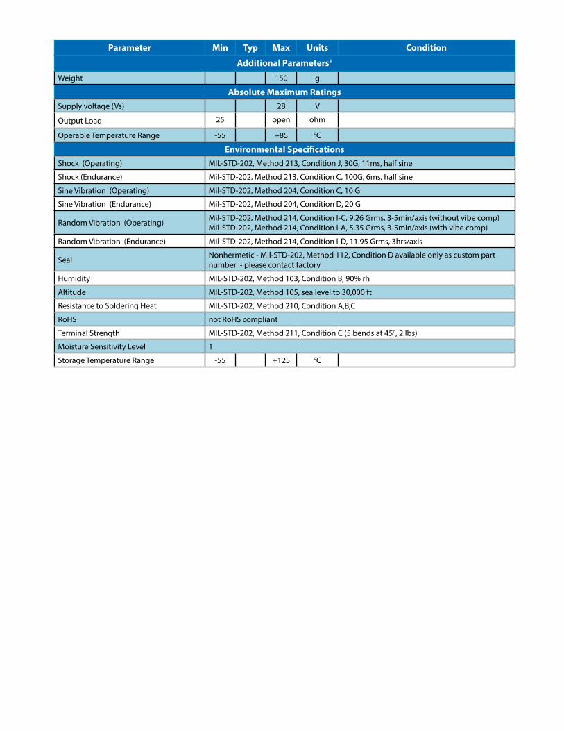
Additional Parameters1
Weight 150 g
Absolute Maximum RatingsSupply voltage (Vs) 28 V
Output Load 25 open ohm
Operable Temperature Range -55 +85 °C
Environmental SpecificationsShock (Operating) MIL-STD-202, Method 213, Condition J, 30G, 11ms, half sine
Shock (Endurance) Mil-STD-202, Method 213, Condition C, 100G, 6ms, half sine
Sine Vibration (Operating) Mil-STD-202, Method 204, Condition C, 10 G
Sine Vibration (Endurance) Mil-STD-202, Method 204, Condition D, 20 G
Random Vibration (Operating) Mil-STD-202, Method 214, Condition I-C, 9.26 Grms, 3-5min/axis (without vibe comp)Mil-STD-202, Method 214, Condition I-A, 5.35 Grms, 3-5min/axis (with vibe comp)
Random Vibration (Endurance) Mil-STD-202, Method 214, Condition I-D, 11.95 Grms, 3hrs/axis
Seal Nonhermetic - Mil-STD-202, Method 112, Condition D available only as custom part number - please contact factory
Humidity MIL-STD-202, Method 103, Condition B, 90% rh
Altitude MIL-STD-202, Method 105, sea level to 30,000 ft
Resistance to Soldering Heat MIL-STD-202, Method 210, Condition A,B,C
RoHS not RoHS compliant
Terminal Strength MIL-STD-202, Method 211, Condition C (5 bends at 45o, 2 lbs)
Moisture Sensitivity Level 1
Storage Temperature Range -55 +125 °C

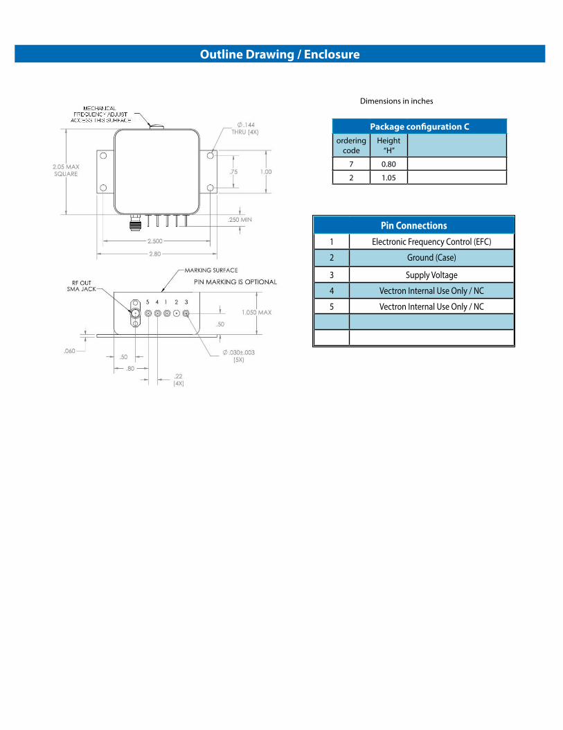
Dimensions in inches
Pin Connections1 Electronic Frequency Control (EFC)
2 Ground (Case)
3 Supply Voltage
4 Vectron Internal Use Only / NC
5 Vectron Internal Use Only / NC
Outline Drawing / Enclosure
Package configuration Aordering
codeHeight
“H”
5 0.80
0 1.05
Dimensions in inches
Pin Connections1 Electronic Frequency Control (EFC)
2 Ground (Case)
3 Supply Voltage
4 Vectron Internal Use Only / NC
5 Vectron Internal Use Only / NC
Outline Drawing / Enclosure
Package configuration Cordering
codeHeight
“H”
7 0.80
2 1.05

Ordering Information4
OX - 043 0 - A E T-509 0 - 10M0000000
Product FamilyOX: OCXO
Package50 x 50 mm
Mounting Style0: Type A,1.052:Type C, 1.055: Type A, 0.807:Type C, 0.80
Supply VoltageA: 15 VdcB: 12 Vdc
Frequency
Platform CodeLow G, Compensation option, Phase noise0: Standard Crystal1: Low G Crystal3: Low G-Crystal, w\vibe comp5: Standard Crystal, low noise option6: Low G-Crystal, low noise option7: Low G-Crystal, w\vibe comp, low noise option
Rev: 5/6/2019 jar
RF Output CodeE: Sinewave
Temperature Range / Stability CodeE-308: -40°C to +85°C, ±30 ppbD-208: -40°C to +70°C, ±20 ppbJ-108: -20°C to +70°C, ±10 ppbT-509: 0°C to +70°C, ±5 ppb
Additional ordering options available include custom temperature ranges, custom temperature stabilities, custom phase noise requirements, custom height, custom supply voltage, hermetic option, and improved g-sensitvity. These modifications require a custom dash number - please contact the factory for additional information.
Additional Ordering Options
Vectron stocks the following items for small orders and prototype development:
OX-0437-AEE-3087-10M000000
Vectron stocks the following evaluation board for this product:
None
Application Notes:
None
Design Tools
Notes:1. Unless otherwise stated, all values are valid after warm-up time and refer to typical conditions for supply voltage, frequency control voltage, load, and temperature (25°C).2. Retrace is defined as the frequency difference between the end of two 24 hour on power periods with a 24 hour off period in between while at a constant temperature.3. Phase noise degrades with increasing output frequency.4. Not all options and codes available at all frequencies.
Contact Information
USA: 100 Watts Street
Mt Holly Springs, PA 17065Tel: 1.717.486.3411Fax: 1.717.486.5920
Europe:Landstrasse
74924 Neckarbischofsheim Germany
Tel: +49 (0) 7268.801.0Fax: +49 (0) 7268.801.281
Information contained in this publication regarding device applications and the like is provided only for your convenience and may be superseded by updates. It is your reasonability to ensure that your application meets with your specifications. MICROCHIP MAKES NO REPRESENTATION OR WARRANTIES OF ANY KIND WHETHER EXPRESS OR IMPLIED, WRITTEN OR ORAL, STATU-TORY OR OTHERWISE, RELATED TO THE INFORMATION INCLUDING, BUT NOT LIMITED TO ITS CONDITION, QUALITY, PERFOR-MANCE, MERCHANTABILITY OR FITNESS FOR PURPOSE. Microchip disclaims all liability arising from this information and its use. Use of Microchip devices in life support and/or safety applications is entirely at the buyer’s risk, and the buyer agrees to defend, indemnify and hold harmless Microchip from any and all damages, claims, suits, or expenses resulting from such use. No licenses are conveyed, implicitly, or otherwise, under any Microchip intellectual property rights unless otherwise stated.
TrademarksThe Microchip and Vectron names and logos are registered trademarks of Microchip Technology Incorporated in the U.S.A. and other countries.