(pages) ° =d (category) agc 8800-12
TRANSCRIPT

(pAGES)
_° ........ =D_ (CATEGORY)
GPO PRICE $
CFSTI PRICE(S) $,
Hard copy (HC) ,_ (_ _
Microfiche (MF) '" ?
ff 653 July 65
AERODYNAMIC DESIGN AND ESTIMATED
PERFORMANCEOF A TWO-STAGE
CURTIS TURBINE FORTHE LIQUID OXYGEN
TURBOPUMP OF THEM-1 ENGINE
NASA CR 54764AGC 8800-12
By
R. Beer
Prepared for
National Aeronautics.and Space Administration
Contract NAS 3-2555
, %
AEROJET
AEROJET-GENERAL CORPORATION
SACRAMENTO, CALIFORNIA
NASA CR-54764AOC 8800-12
TECHNOLOGY REPORT
AERODYNAMIC DESIGN AND ESTIMATED PERFORMANCE OF A
TWO-STAGE CURTIS TURBINE FOR THE
LIQUID OXYGEN TURBOPUMP OF THE M-I ENGINE
Prepared For
NATIONAL AERONAUTICS AND SPACE ADMINISTRATION
19 November 1965
CONTRACT NAS3-2555
PREPARED BY:
AEROJET-GENERAL CORPORATION
LIQUID ROCKET OPERATIONS
SACRAjV_NTO, CALIFORNIA
TECHNICAL MANAGEMENT:
NASA LEWIS RESEARCH CENTER
CLEVELAND, OHIO
KUTHOR_ R. Beer TECHNICAL MANAGER: W. W. Wilcox
APPRO_ED : Wo E. Campbell
Assistant Manager
H-I Turbopump Project
APPROVED: Wo F. Dankhoff
M-I Project Manager


ABSTRACT
i
A two=stage Curtis turbine was designed for use in the oxidizer turbopump
of the M-1 Engine°
At its design point, the turbine produces 26,800 horsepower at a velocity
ratio of o133 and an estimated efficiency of °53°
Blunt edged turbine rotor airfoils are used throughout° Beside superior
performance at subsonic Mach numbers, these airfoils (in the form of hollow sheet
metal blades) offer advantages in fabricability, thermal fatigue resistance, and
weight savings as compared to airfoils with sharp leading and trailing edges°
/ r
iii

TABLE OF CONTENTS
Io
II.
III.
SUMMARY
INTRODUCTION
DESIGN
Ao REQUIREMENTS AND GAS PROPERTIES
Bo DESIGN PHILOSOPHY
Co AERO-THERMODYNAMIC DESIGN
io Flow Quantities at Mean Diameter
Do
e
a. Loss Estimate
b. Performance
Flow Quantities at Hub and Tip
BLADE DESIGN
2o
3.
Solidity
Blade Profiles
Determination of Cascade Exit Angles
o
5.
Flow Areas
Velocity Distribution on Profiles
ao
bo
BIBLIOGRAPHY
APPENDICES
A o NOMENCLATURE
Bo
NASA Computer Program
Vavra Potential Flow Method
ESTIMATIhG LOSSES IN A TURBINE CASCADE
rI
i
3
3
3
ii
ii
ii
14
14
14
14
21
28
28
3o
3o
3o
4]
iv


LIST OF TABLES
NOo
o
,!4o
o
2o
3o
5o
6o
_u
o
9o
,]0o
!!o
12,,
]$o
Title
M=I Engine Liquid Oxygen Turbopump Turbine Design
Parameters
Flow Quantities at the Mean Diameter
Flow Quantities at Hub_ Mean s and Tip
Determination of Throat Areas and Blade Heights
a,.,._iOF FIGURES
M_l Engine Mockup
Nozzle Assembly
Reversing Vane Assembly
Rotor Assembly
Estimated Turbine Efficiency VSo Velocity Ratio
Properties of Combust:ion Products of Hydrogen and Oxygen
for a Mixture Ratio O/F : o8 and M = 3_63_R : 4?6 _=' Io± = ft
ibm = OR
Efficiency of Two-Stage Curtis Turbines VSo Co/U andReaction Distribution
Blade Configuration used to Compare Different Methods
for the Loss Prediction of a Rotor Blading
Rotor Velocity Loss Coefficient for Impulse Turbines
E×pansion Process _n T_S Chart
Ve!_oci<y Triangles a< the Mean Diameter
Sea! Arrangement Assumed in Performance Calculations
Velocity Triangles a_ Hub_ Mean s and Tip
Page
8
15
19
31
10
12
13
16
17
18
20
LIST OFFIGURES(CONT'D)
NOo
14o
15o
16o
17o
18o
19o
20o
21o
220
230
24o
25°
26°
Title
Impulse Profiles for Large Turning Angles
Comparison of the Velocity Coefficients of Blades
with Blunt and Sharp Leading Edges
Nozzle Vane Profile and Coordinates
Rotor Blade Profile and Coordinates
Blade Layout
Axial Plan in Hot Condition
Gas Efflux Angle from Turbine Blade Cascade
Example of the Preparation of the Computer Input
for the First Rotor
Velocity Distribution for Nozzle, 43 Vanes
Velocity Distribution and Separation Parameter for
First Rotor, 98 Blades
Velocity Distribution for Reversing Vanes, 93 Blades
Velocity Distribution for Second Rotor, 88 Blades
Velocity Distribution for Second Rotor, Comparison of
82, 88, and 98 Blades
Pag._e
22
23
24
25
26
27
29
32
35
36
38
39
40
vi

I o SUMMARY
This report delineates the aero-thermodynamic design of a Curtis turbinedesigned for the oxidizer turbopumpOf the M-I Engine. At the design point, theturbine produces 26,800 horsepower at an estimated efficiency of 53_.
The turbine design parameters are:
Inlet total pressure (at nozzle inlet)Inlet total temperature (at nozzle inlet)Outlet static pressurePressure ratio, total to staticMass flowSpeedMeandiameter of first stageBlade-jet speed ratio
psia 200°R 1190psia 120--- 1o67ib/sec 115rpm 3635in. 33.00.... •133
Blunt edged turbine rotor airfoils are used throughout° Besides superiorperformance at subsonic Machnumbers, these airfoils (in the form of hollow sheetmetal blades) offer advantages in fabricability, thermal fatigue resistance, andweight savings as comparedto airfoils with sharp leading and trailing edges.
iIo INTRODUCTION
The pumping system of the liquid propellant M-I engine consists of twoseparate turbopumps_ each having a direct-drive turbine. A gas generator, separatefrom the main engine_ supplies the turbines, which are arranged in series, with thecombustion products of liquid hydrogen and liquid oxygen° The gas is initiallyexpandedin the fuel turbine and then further expandedin the oxidizer turbine° Theexhaust from the oxidizer turbine is used in three heat exchangers; to heat hydrogenfor the gimbal actuators, and to heat hydrogen and oxygen for tank pressurization°The oxidizer exhaust is then used to cool the lower section of the skirt of themain nozzle° Finally, the exhaust is ejected via a set of small nozzles to providean approximate specific impulse of 260 ibf-sec (See Figure i).
Ibm
Initially, single stage turbines were designed for the fuel and oxidizerturbopumpso The single stage turbine rotor for the liquid oxygen turbopumpwasfabricated from a solid forging and was used in the initial test series as a workhorsemodel° For the development engine a two-stage Curtis Turbine was specified and theaerodynamic design of this unit is the subject of this report° This turbine has notbeen tested full scale under hot conditions° However_actual experimental perform-ance data of the inlet manifold, turbine nozzle, and complete two-stage turbine hasbeen obtained in cold air on a subscale model at Lewis Research Center° Thiseffort will be reported separately by NASA. In addition, the fabrication methodsused on both rotors and stators_ and the design and fabrication of the uniqueintegrated pumpbackplate-turbine inlet manifold will be discussed in separatecontractor reports°
Page i
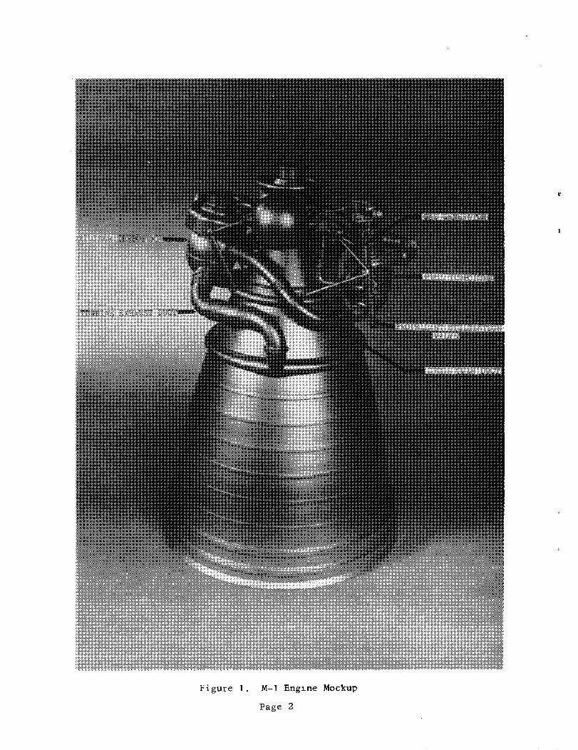
Pigure I. M-I Englne Mockup
Page 2

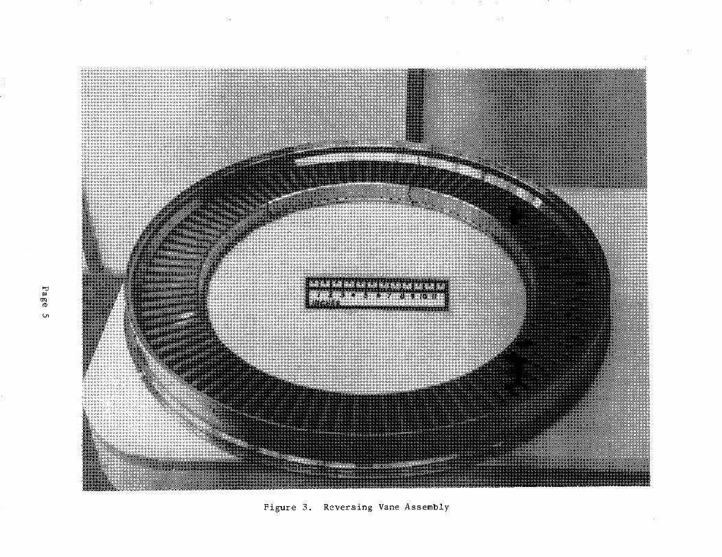
TLe nozzle_ reversln_ vane and rotor assemblies were fabricated entirely from,
Incor_,el 7!8 component parts and weld assembled by the process of Electron Beam,
Weldir4_o Figures 2_ 3 and. 4 show photographs of the nozzle assembly (Figure 2)_
tlhe reversir_ vane assembly (Figure 3) and the dual rotor assembly mounted to hub
and shaft° (Figure 4)
II! o DESIGN
T'rA. REQuIREM_NT.S AKtD GAS PROPERTIES
Figure i shows a photograph of the engine mockup indicating the ducting
elements° At the design point_ 14_ of the total flow available from the gas generator
(to drive both turbines) by-passes the fuel turbine° The by-pass flow and the fuel
tu:ffbine exhaust fiow are carried through two !lo4-in° (inside diameter) cross-over
ducts to the oxidizer turbine inlet manifold° This manifold is considered to be part
of the ductir_ and the turbine inlet conditions specified in this report apply to the
ann_,l_,s ..._,4-,dz_ec_,ly upstream from the nozzles° It is assumed that the manifold provides_s_:iEcrm.nozzle i:_,l,etconditions over the entire circumference°
An_ engine system balance was perform,ed based upon an assumed variation
of the turbine efficiency versus the velocity ratio (U/Co) as shown on Figure 5 and
upon estimated cross-over duct pressure losses° This engine system balance resulted
in the design parameters presented as Table i°
_.e properties of t:he turbine gas_ w:hich is the combustion product of
___e 6° _he effect of the pressureliquid hydrogen and liquid oxygen, are shown as ....._ ......
•u(ponCp and Tis neglected° A_so_ Cp and T are taken at the reference temperatureof !I30°R and kept constant th_.oughout the tu:#bine. The gas properties used are as
foilows_
o/F o8
IBo
c i. 984P
1.382
_-i °2765Y
-_ 3.62
R 426
DESIGN :E_:ILOSOPHY
• /. oB._], ibm,- R
Ibf_ft
lbm-_
The maximum total-to_-static efficiency of a turbine stage is pre-
d,oc...i,zl.an._ly a function of the J/Co ratio of tb.e stage° At different U/Co ratios_
ma.z×im:um e.:fficier_'cies are obtain.ed with d.iffe:rerzt reaction distrfbut:ions between
stator and. rot:o:r° Figure 7 (1) shows tb.e eff:iciency of a two stage Cu:rtis turbine
ve:rsus Co/:[ and. reaction distribution° For [i[/'Co : 0.1.33 or Co/U = 7o5_ tlhe
Fiugeff._ Ou,stav., Die Dam_b_ :ihre Be:rechn:an_ff_ und Konstz'i_.kt:ion mit_i-_m An.hang u.ber die ¢::= ,_ ° -_........... ,,._st._._.b.zn_n, Johann Amb:rosius Bartb._ Leipzig_ 1931_page _7
Page 3

E
t_
Nt_0
Z
t:tO°,._
,!Page 4
_o
fD
L_
Figure 3. Reversing Vane Assembly

Figure 4. Rotor Assembly
Page 6

I ,1
!M
I:i
!i _ '
:iii
.i!i
TIT1}+ +
]! I.i4%4
Estlmated Turbine Efficiency vs Velocity Ratio
Page 7
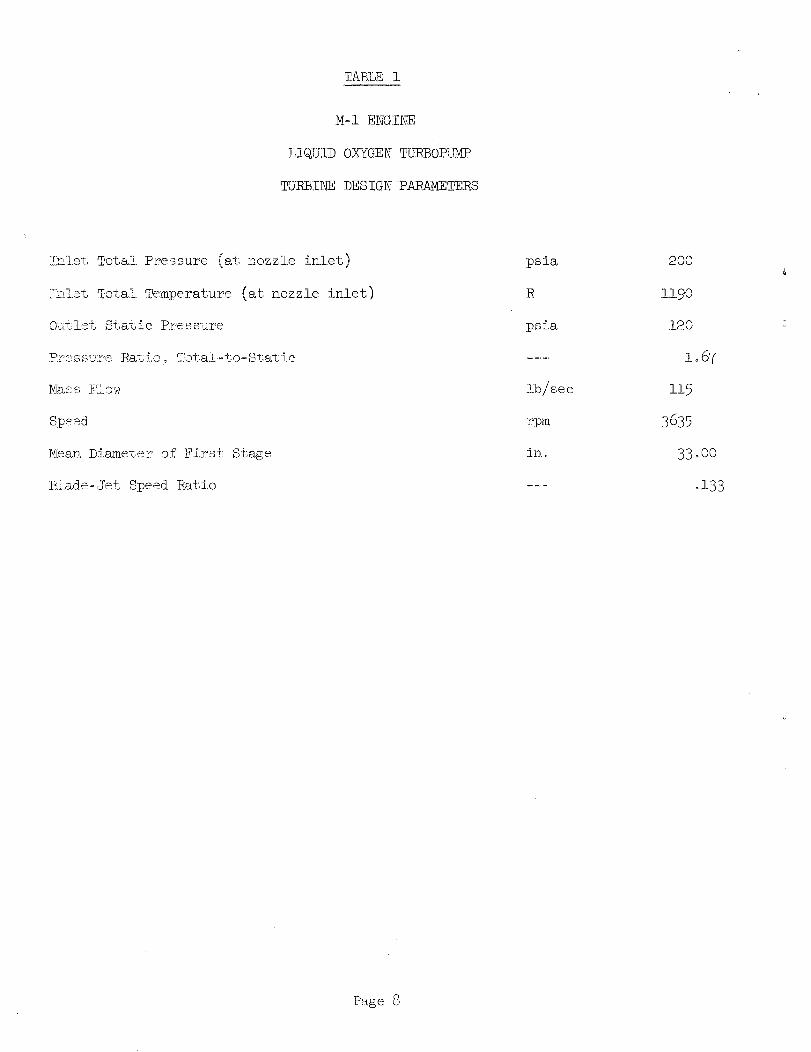
TABLE I
M-I ENGINE
LIQUID OXYGEN' TURBOPDMP
_JRBINE DESIGN PARAMETERS
Inlet if'oral Pressure (at nozzle inlet)
Fk£et Total. Tempe:rature (at nozzle inlet)
O_:tle% Sta%ic Rressu.re
P:ress'u.re Ratio._, Totaf.-to_Stat:i.c
Mass FAow
Speed
Mean. Diameter of Fi:rst Stage
iEiad.e-.Jet Speed Ratio
psia
R
psia
lb/sec
rpm
in,
200
ll90
120
io 67
115
3635
33°00
o133
Page 8

Figure 6. Properties of Combustlon Products of Hydrogen and Oxygen
for a Mixture Ratio O/F = .8 and M = 3.63,
ibf - ftR = 426
ibm - °R
Page 9

y
REACTION DISTRIBUTION
01
!!
/S2"
0
o
o
Figure 7. Efficiency of Two-Stage Curtis Turbines vs Co/U andReaction Distribution
Page 1 0

reaction distribution 0-0-0 is recommended. This means that the entire static
pressure drop (or static enthalpy drop) is taken in the nozzle of the first stage
and no static enthaipy drops occur in the rotors of the first and second stages
and reversing vanes° However_ preliminary calculations indicated that this reaction
distribution results in undesirably long blades in the second rotor°
The reaction distribution finally selected, 0-3-7_ has no enthalpy drop
in the first stage rotor_ 3_ of over-all available enthalpy drop in the reversing
vanes and 7_ of over-all available enthalpy drop in the second stage rotor° This
results in desired blade heights with only a small loss in performance°
Co AER0-THERMODYNAMIC DESIGN
io Flow Quantities at Mean Diameter
ao Loss Estimate
It appeared that the rotor velocity coefficients, previously
used at Aerojet-General in the design of turbines,were too conservative for the M-I
Engine oxidizer turbine. _.is M-1 oxidizer turbine has a nozzle height in excess of
3-ino_ a rotor blade width of approximately 1.5-in., and only subsonic Velocities
throughout its blading° It is expected to have high blading efficiencieso Because
information concerning the losses in turbine bladings similar to the ones to be
designed were not available_ a published method of loss estimation was selected(2).
_is method for loss estimation is summarized in Appendix B.
Prior to the selection of this method, the velocity coefficient
of the rotor blade shown in Figure 8 was calculated using five different methods for
comparison purposes. The results were as follows:
KR = wjw&
Stenning (3) °94
Traupel (4) .90
Vavra (5) .86
Aerojet-General (Figure 9)
Ainley (6) (extrapolated)
.835
°80
<!raupel provides the most realistic answer and his method was selected as mentioned
above°
_iraupel, Walter, _ermische _.rbomaschinen, Erster Band_ Springer Verlag/
Be rfin/Go tt ing en/Hee_elb erg] 1958
(3} Stennis_ Alan Ho_ Design of T_rbines for High-Energy-Fuel-Low-Power-Output
£pplieat:ions_ HIT Report No. 79
(4) Traupel_ Walter, opo cito
Vavra_ M° Ko, Analysis and Design of Modified 87- 5 Turbine, AGLR No° 3_ April 1962
(6) Ainley, Do Go and Mathieson_ Go Co Ro, A Method of Performance Estimation for
Axial_Flow T!z:rbines_ R_M 2974_ December 1951
Page !l

Figure 8. Blade Configuration Used to Compare Different Methods
for the Loss Prediction of a Rotor Blading
Page 1 2

Figure 9. Rotor Velocity Loss Coefficient for Impulse Turbines
Page 13

b o Performance
Based upon the loss estimation discussed in the preceding sec-
tion_ the expansion process in the T-S Chart and the velocity triangles were calculated
for the mean diameter° The pertinent results from these calculations are provided
as Table 2o Figure i0 shows the process in the T-S Chart and Figure ii shows the veloc-
ity triangles at the mean diameter. A total-to-static efficiency of 56o7_ was obtained
from these calculations. This appears to represent the potential for this design
after some development. Therefore, it was decided to use 53°0_ as a conservative
estimate for the engine system balance (see Figure 5). These efficiencies are based
upon the seal arrangement shown in Figure 12 with axial clearances, k , of nota
larger than ol00-ino
2. Flow Quantities at Hub and Tip
An untwisted sheet metal blade of constant cross-section was
selected for all blade rows. As a result, the gas outlet angle of each blade row
is nearly constant from hub to tip° The flow quantities at hub and tip were calcu-
lated from radial equilibrium considerations, assuming constant gas outlet angles,
and using the method given by Traupel(7). The flow efficiencies were assumed to be
constant from hub to tip. Results are presented in Table 3 and Figure 13o The loss
coefficients used in the radial equilibrium calculations differ from those used in
the performance calculations because the flow quantities at the hub and tip were
calculated for a preliminary configuration which differed slightly from the final
design selected. However, in view of the slight difference it was not considered
necessary to recalculate the flow quantities at the hub and tip for the final
configuration°
D° BLADE DESIGN
lo Solidity
The loss system detailed in Appendix B requires that optimum solid-
ities be used as shown on Figure B-2 of that appendix° Actual and optimum solidities
for the four blade rows are as follows_
Nozzle First Rotor Revo Row Second Rotor
Number of Blades 43 98 97 94
Actual 1o54 io525 io51 1o46
Optimum io22-io42 io47_i.80 io46_io78 1o44-I.o76
(7) Traupel, Walter_ Opo cito
Page 14

TABLE2
FLOW QD'ANTiTIES AT _LE MEAN DIAMETER
Nozzle Nozzle Rotor I Rev.Vane Rotor II
Dim Inlet Outlet Outlet Outlet Outlet
PT psia 200 193.0 151.2 146o i 128o 2
PTR psia 174o 5 163o 2 137o 5 134.6
'-2T °R 1190 1190 1133.3 1133.3 1099o 5
TTR °R - 1157o 5 1157.5 1114o7 lllho•7
T °R - 1061 1080o 3 1085.5 1080o 3s
P ps ia 126.8 126.8 124o 8 120.0S
Z 7"V ft/sec 0 3575 2290 21 2 1388
...... _+/.... 524 52k 522 52o
W ft/sec 3090 2765 !700 1850
degrees _ 90 70.00 -63.10 67°00 -56°50
degrees - 66°65 -68.00 60ol.0 -65.50
D inch 33 33° O0 133oO0 33. O0 32.80:m
:h.d. inob. - 3,20 3° 90 4,80 5,55A b inch, - o400 .500 .4,00 -
HI - - o800 .509 °481 •309
HR - - .693 ,614 •377 .410
p l%m/ft 3 - .0407 .0401 .0392 .0379
STAGE ! STAGE II• i ....B TJ
L _ 112 °2 66°0u ]]bm
qu ¢ 64.2 -
que {o - 48.6
OVER-ALL_ L = 178.2 BTU/IbmU
L. : 176 B_J/ibmi
qi* = 56o7¢ -
N _ 1......................... ' [.] ........................
Nozzle Rotor I Revo Vanes Rotor II
Nb.mber o:f' %,ff.ades
70." _ :-1 i t-,,--J_"
2'_' _i _k-,,,m_#. Area iirz°r ,±.9,,,..e ..............
Reaet:ior;, <Rx/.
43 98 97 9 4
o91 °80 .83 °86
I11°5 14.1.5 184o5 227°5
•9 0 °03 °07
Page 15
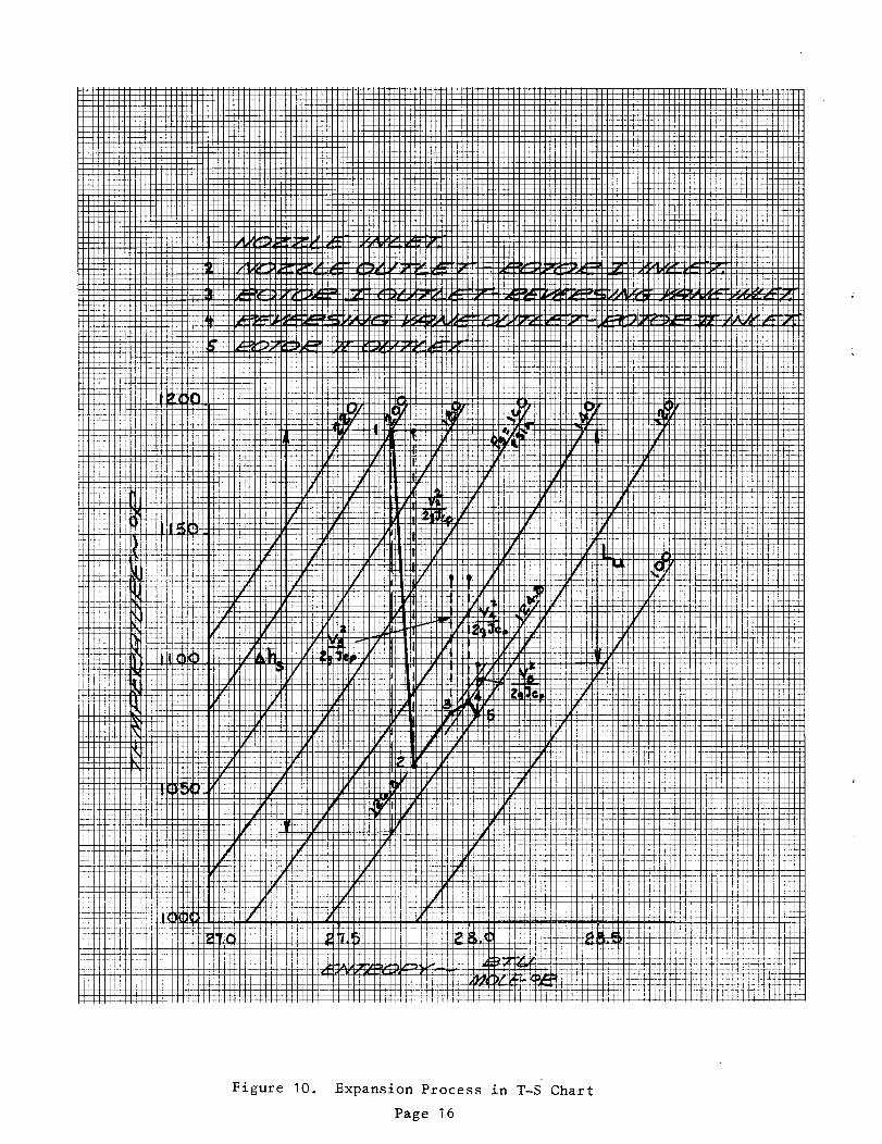
Figure 10. Expansion Process in T-S Chart
Page 16

Pigure 11. Velocity Triangles at the Mean Diameter
Page 17

\
Figure ]2. Seal Arrangement Assumed in Performance Calculat±ons
Page 18

TABLE 3
FLOW QUANTITIES AT HUB, MEAN,AND TIP
(Configuration slightly different than that finally selected)
m
D in.
r ft
PT psia
PS psia
T T °R
T
lb/ft3
V ft/sec
U ft/see
W ft/sec
o
8 °
_Vxr lhmft.-see.
rV_ ft.2/sec.
HUB
Nozzle Nozzle Rotor I
Inlet Outlet Outlet
29.79 29.29 29.07
1.240 1.240 1.210
200.0
200.0 113.5 119.2
1190 1190 1133.8
1190 1038 1067.8
.0380 .0382
3880 2560
472 461
- 3440 2980
0 70_0 -64.1
- 67.3 -68.0
- 63.0 51.5
4525 -2780
.r
= 2_'J_ t _Vxr dr
r h
MEAN
Rev.Vane Rotor II Nozzle Nozzle Rotor I Rev. Vane Rotor II
Outlet Outlet
28.08 27.18
1,170 1.152
- 124.0
115.0 113.0
1133.8 1102.5
1072.0 1080.8
.0367 .0364
2475 1445
445 431
2070 1850
67.0 -39.1
62.2 -66.0
41.4 31.0
2660 -1423
Nozzle
Inlet
INLET Outlet Outlet Outlet Outlet
33.00 33.00 52.90 32.90 35.00
1.575 1.375 1.570 1.370 1.375
200.0 - 127.2
200.0 126.8 126.8 124.8 120.0
1190 1190 1155.0 1153.0 1100.9
1190 1061 1080.5 1086.4 1085.8
.0407 .0401 .0393 .O380
3370 2299 2130 1300
524 522 522 524
3080 2770 1680 1760
0 70.0 -63.1 67.0 -56.6
66.7 -68.0 60.0 -66.0
68.2 57.1 45.2 37.4
4620 -2810 2710 -1488
TIP
N'ozzle Nozzle Rotor I
INLET Outlet Outlet
36.21 36.21 36.73
1.510 1.510 1.330
200.0
200.0 136.0 132.2
1190 1190 1132.4
1190 1081 1088.6
.0429 .0413
3310 2080
573 582
2770 2615
0 70.0 -61.9
65.9 -68,0
73.1 62.2
- 4700 -2810
r t
_L u = 21_w _r _Vxr A(rY u) dr
h
Nozzle Rotor
Outlet Outlet
Rev. Vane
Outlet
115.2 113 .O 113.8
Rev.Vane
Outlet
37.32
1.370
132.2
1132.4
1097.2
.0412
1868
598
1340
67.0
56.1
48.3
2685
General:
Stage I
12950
Stage II
7290
}P = 1.415(12930 + 7290) = 28600
The calculations above are based on the following biading efficienc_es:
Nozzle I Rotor I.91 .81
Rev. Vane Rotor II ]
J.81 .79
Rotor II
Outlet
38.82
1.618
130.5
124.4
1100.3
1086.7
.0391
1162
615
1695
-33o5
-66.0
43.6
-1512
Rotor II
Outlet
114.5
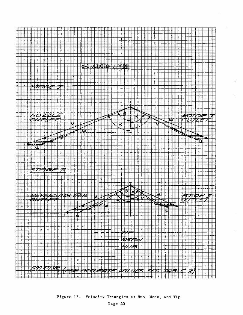
Figure 13. Velocity Triangles a% Hub, Mean, and Tip
Page 20
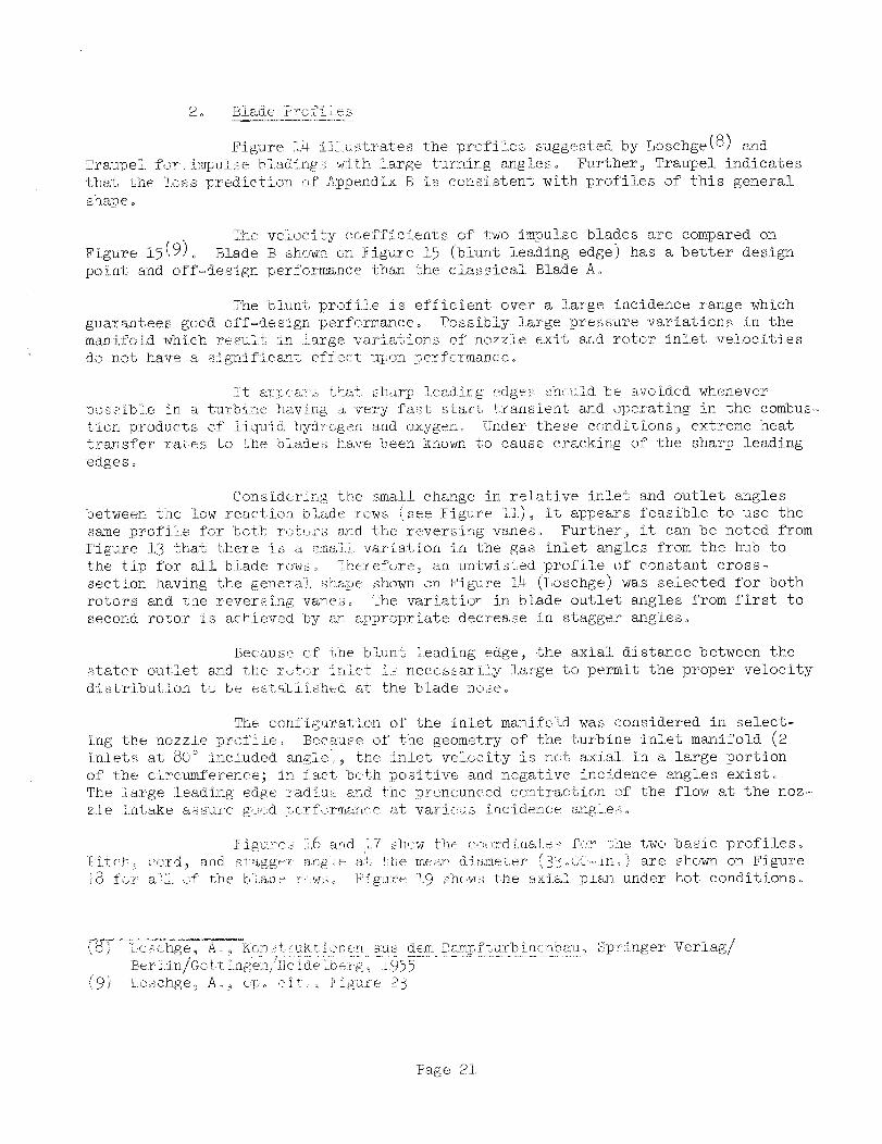
2o Biade ?r<,_file _,
Figu:re i.4 :i]£ustrates the profiles suggested by Loschge(8) and
Traupel fo:r.imlpulse bla,dlng_ with !.argo turning a;ngleso Further_ Traupel indicates
that the Loss p:red.ie%:ion of Appendix B is consistent with profiles of this general
shape o
The veLocity coefficients of two impu].se blades are compared on
Figure 15(9) o Blade B shown o:n Figure 15 (blunt leading edge) has a better design
point and. off_..design performance than the classical Blade A o
The blunt profile is efficient over a large incidence range which
guarantees good. off=design performance° Possibly large pressure variations in the
manifold which result in large variations of nozzle exit a:<d rotor inlet velocities
do not have a significant effect upon performance°
!t at<_ea,_::_ tha,'t sharp !.ead:i:_g ed.ge,_ slh<.ul.d be avo:ided whenever
pos_::ibie in a tu:-<%ine ha, v:i.ng ._ very fast sta:rt %:ransiemt and ope:_at:ing in the combus-
tion products o:f liquid hydrogen and oxygen° Under these eonditions_ extreme heat
transfer rates to tae blades ha;re been known to cause cracking of the sharp leading
edges°
Conside.ring fihe small change in re].ative inlet and outlet angles
between the low reaction blade :rows (see Figure L,_j''"_ it appears feasible to use the
same profile for both :_{)t,_:rsand the reversing vanes° Further_ it can be noted, from
Figare 11.3that there is a small variation in the gas inlet angles from the hub to
the tip for all blade rows° 7herefore_ an untwisted profile of constant cross.-
section having the genera]., shape shown on Figure 114.(Loschge) was selected for both
rotors and the :reversing vanes° The variation in blade outlet angles from first to
second, rotor is achieved by an _ppropriate decrease in stagger angles°
Because of the blunt leadLng edge_ the axial, distance between the
stator outlet and the rotor inlet i_{ necessarilj large to permit the proper velocity
distribution to be e:at_biished at the blade nose°
The configuration of th.e inlet ma,nifoid was considered in select-
ing the nozzle profile° Because of the geometry of the turbine inlet manifold (2
inlets at 80 ° iuckuded angle)_ the inlet velocity is not axial in a large portion
of the circumfe:rence; :in fact beth positive and negative incidence angles exist°
The large leading edge radiu_ and the pronounced contraction of the flow at the noz-
zle :intake assure g,_.,d perfor:man_e at various incidence aagieso
Figure_ 1i,6 a:od k'7 sh<:w _ - ba_._l, profiles.... ohm: co.::_-dinate_ f<<r ffhe two ' _:°c o
i[:itcb-_cord_ and s_agg_<r a:ngK.e at t_',emean diameter (3_!o0£<ino) are shown on Figure
].8 fo_ alk of the bka,J__ :_,WSo Figure 11.9slhows the axial, pia,n under hot conditions°
_'_ Lcsc:hge_ R. _ Kc,:o..t:,'uktiore:u a;u_ dem Dampftu:Ybine:@bau_ Springer Veriag/
Bet Pn Goft ng_ _-He_d_, b_g_ 955
(9') _oschge_ A,_ _._o tit _ _'ig'ure 213
Page 21,

LOSCHGE
JJ/J/
T_L_UPEL
J_J
Figure 14. Impulse Profiles for Large Turning Angles
Page 22

1,0
.9
.7
K .5
•9 --
.2
.I
0
/ ' _At
/ I/
-- - Ir,_g_-_.
)o _o 3o _o _o _o 7o 80 90 ,oo -_ 90 _- _ = 57---Z
• k
.\\\%
D
E
- t'_.s-IIILET_ B_? = ¢_ _--OLITL ET)
Figure 15. Comparison of the Velocity Coefficients of Bladeswith Blunt and Sharp Leading Edges
Page 23
00_'-
012"_ ----
H.tOOWg
4_
0
0
,,-t
o
¢;
N
0
b_.,,-I
¢x1

moq
bo
ot,t-0t-1
13,
0I-h
t_
13.
00I-t
t_
SMOOTH T RANSITION B _Tk,4 & &l'4
=- I. _4- _ I. 5 _o _----A---
D E F" INP...D p oI NIT,,%
l-----.& 9, --2 --1
__,,L
.O't3'
I ............ !
i
[
,G._8 R TO I_LENO
0
8 PLACE5

\
m
b_
.810
\
43NOZZLE 5LADE5
_ECTION TAKEN AT
STATOR
33.000 DIA
2.° ROTOR
I_ 1.000
Figure 18. Blade Layout

C
g
X
_cl m
I-L
_°
O
C_0
O.
0
BLADE THROA'I" ARP-..A- INZ: 111,5 141.5 184,.5 ,9_.7.5
10 °
I. !00
HONEYCOMB
_j,,,
o,o._1,:;_°
-,_-. 100
REF
_."fO0
_. 85O
-V-
---.100
AXIAL PLAIxI_ t-lOT CONDITIONS
CLEAI_ANC, ES SI--tOWN FOI_ I{'UI_KIIKI_ CONDITION,._
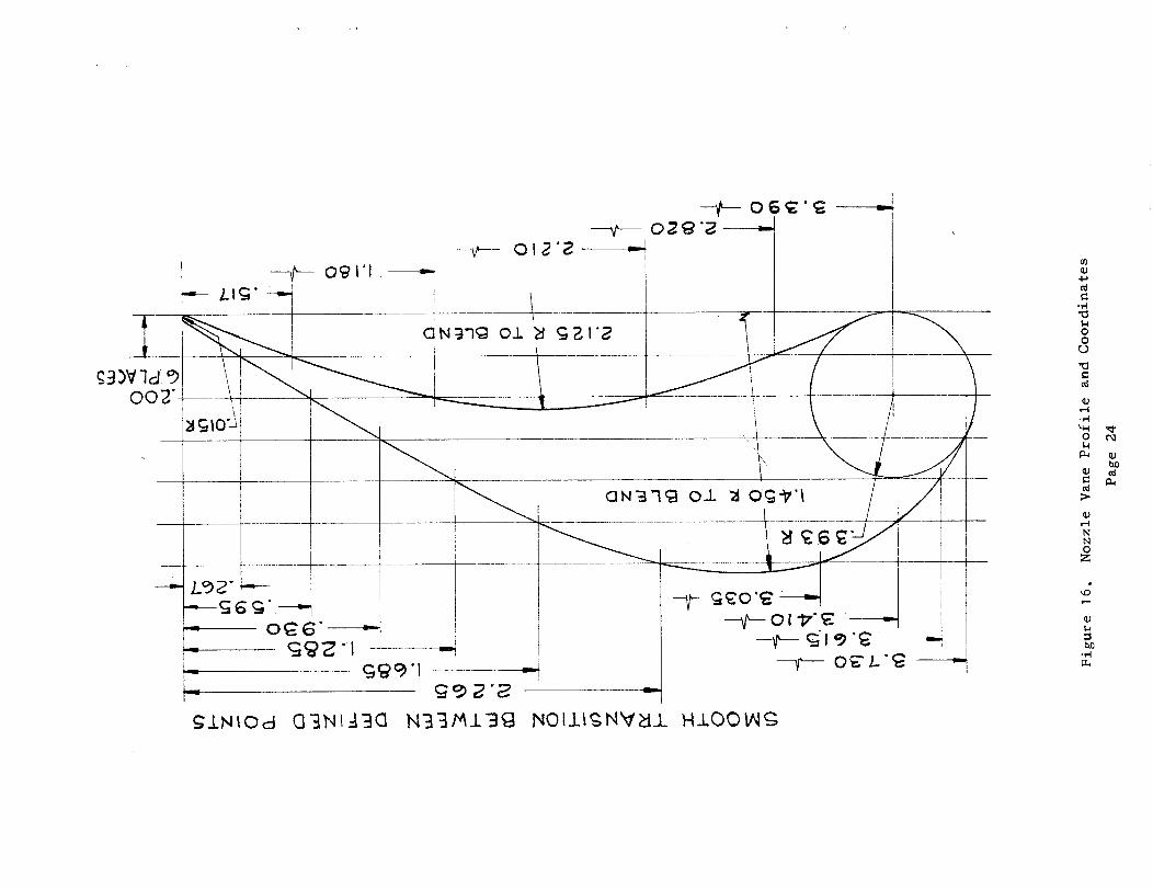
3. Determination of Cascade Exit Angles
Four different methods were used to make an estimation of the gas
outlet angle for an assumed blade row with the following results:
MethodOutlet Angle
Ainley (10) 67.3
Traupel (II) 66.3
Zappa (12) 65.0
Markov (13) 65.1
Because the tangential component of the velocity is responsible for
the specific work of the stage_ it is preferable to select one of the more comse_vative
methods of Zappa or Markovo Zappa is the more convenient to u.seB therefore_ it was
selected for the current design. This method_ illustrated on Figure 20_ expresses
the gas efflux angle of a blade row as a function of the ratios, throat width to pitch
(d/s)_ and trailing edge t:hickness to pitch (te/s)o
4. Flow Areas
The accurate determination of the flow areas is of the utmost importance
for Obtaining the required reaction distribution in the turbine. The performance
calculations from the performance discussion (III, C, i, b) givei?preliminary _alues
of the reaui.red free stream blade height at the exit of the blade rows° These blade
:heights were corrected using Vavra's method(14). The flow through a turbine blade
row is expressed by the equation_
PT _o y - 1
(10)
.LI i,(:1,2)
/, 13)
Ainley 9 :Do @°, O_o cito
U:raupek, Waiter_ op. cito
Zappa, 0., #'lot of Gas Efflux Angle from. _o.rbine :Blade Cascade (l_ivate
Co_:.Jn.icat:.ion) based upon_ _ACiA TN 3802, 1956 (Dunavant z J. Co and Erwin,
Jo B o, Investigation of a Related Series of Tarbine Blade Profiles in
Cascade] and NACA :.EN3959_ :1957 _ J. C°, Cascade Investigation of
a Re:l.aL;edSeries of 6-.Percent !_ick Guide Vane Prof:Lles and Design
Markov_ No Ho_ Calcui.atio:a of the Aerodynamic Characteristics of :Iurbine
B:Lading_ Associated _:echnical Serv'ices Inc., Glen Ridge_ New Jersey, i_8(:i._.)\favra_ Mo Ho, opo cito
Page 28

_00_¢D
to_o
Pigure 20. Gas Efflux Angle from Turbine Blade Cascade
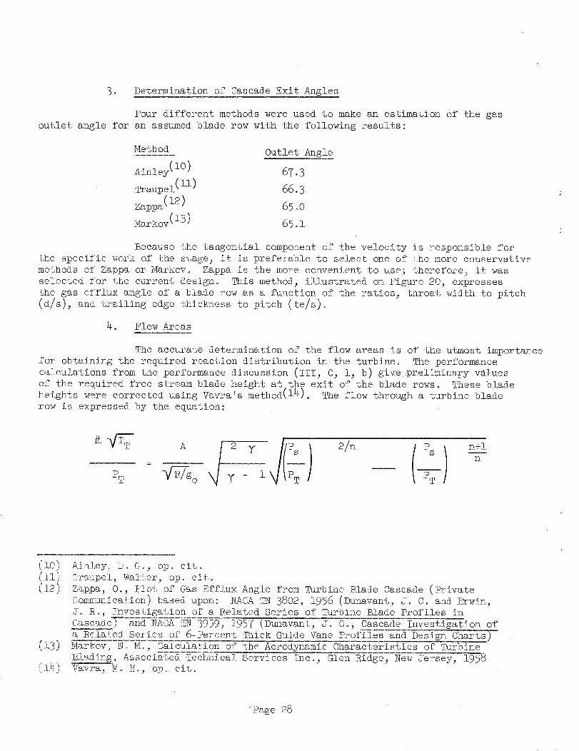
wi<h
nY
y - {p l)
and_ _p : f (Pressure Ratio, Loss)°
Eifferent loss coefficients are used for calculating efficiency and flow areas°
<%e mean polytropic efficiency_ 9 , for the calculation of the flow area is
obtained from the blade efficiencyPwith the following empirical relationship:
[Nozzle: _p : l - .50 (i - lqn )
Rotors and Reversing Vanes: _p : i - .67 (i - qr)
Table 4 shows the results of these calculations and presents a
comparison of the blade heights obtaine@ with •those discussed under performance
(III, C, l, b)o The above equations ,give the blade height at the blade throat
Khile those in the performances discussion give the free stream annulus heights.
5. Velocity Distribution on Profiles
The following two methods were used to estimate the velocity
distributions on the profiles.
ao NASA Computer Program (15)
The accuracy of the results obtained with this method depends
to a large extent upon the accuracy with which the computer input is prepared° It
proved difficult to estimate the effective channel at the inlet to the blades and
as a result, the first points on the suction side outside of the physical channel
were neglected in determining the diffusion parameter° Figure 2]. is an example of
the preparation of the computer input for the first rotor°
bo Vavra Potential Flow Method (116)
_. ° ._±_hl_ method yields tlhe inlet stagnation point and velocity
distrfbut.ionfor any inlet angle° Its limitations are the inherent two-dimensionality
of Lhe field plotter and its restriction to incompressible flow.
(16)
_<_inoon_: Wo Do, Tmrbine. Computer Progrsm,. NASA-Aerojet Computer Job NO o 11009,
Aerojet-Oeneral Corpo Hemorandum dated 27 September 19_-2
'{;"avra_M o Hoj Aero-Thermodynamics and Flow in :_urbomachines, John. Wiley & Sons,
IkJ.Co j New York_London_ 19_
Page 30

TABLE 4
DETERMINATION OF _[ROAT AREAS AND BLADE _[EIGHTS
Nozzle ist Rotor Rev. Vanes 2nd Rotor
- .91 .80 .83 .86
_p - .955 .867 .887 .907
n - 1.361 1.315 1.324 1.335
PT psia 200 174.5 151.2 137.5
T °R 1190 1157.5 1133.9 1.114.7
PS/P,[, - .634 °727 °825 .873
_/A ibm I. 039 .810 .621 5025' 'd. °'
2sec-in.
k 1 1.0055 1.0030 1o0085
Ad _ i 2kK _ in. 111 141.5 184.8 227°0
hd in. 3.19 3.90 4.82 5.55
h_ in. 3.20 3.83 4.78 5.4.6
hd_e in. 3.20 3.90 4.80 5.55
_ A_pendix B Method (reference performance discussion_ Section III_ c, i, b)
** Yinal Selection
Page 31

;IoI #nduI z_nduloD _q_ go UOT_z_dex_ _1% I o _Idw_xK
/I/
I
iI iI
I I
//
//
//
// \
\\\

Results from the velocity distribution analysis are as follows:
The ratio of the surface velocity to the outlet velocity is plotted
in relationship to the distance measured along the blade surfaces from an aribtrary
point, A (_ee Figure 21) (A is not the stagnation point). Because the Vavra method
yields the inlet stagnation point, it is shown for the nozzle and the first rotor.
The remaining two rows of blades were not investigated using the potential, flow method]
therefore_ the velocity at A was assumed to be equal to the inlet velocity,
The stagnation point on the trailing edge, B_ exists only in potential.
flow. Actually, the flow will separate; therefor% this stagnation point is not shown.
Instead it i.s ass_med that the trailing edge surface velocities at the pressure and
sucfion sides are equal to the leaving velocity downstream from the blade row.
Two criteria were used to judge the velocity distribu:tion:
Diffusion Parameter D
Kofskey [17) defines a diffusion
parameter as follows:
D = D +Ds p
where_
D = 1 -s
D = l -
P
w4
W max.s
W rain.P
w3
A desirable value for D is .45. It is thought that the
suction side contributes the major part of the total losses. Therefore_ diffusion
par_neters larger than .45 were accepted providing D s was smaller than approximatelyo25.
DKofskey_ Mo Go_ Cold-Air .erformance Evaluation of a Three-Stage 'i_arbine
having a Bl_,de-Yet Speed Ratio of .156 Designed for a iO0_OOO-Pound-Tr_rust
Hydro6en-O×ygen Rocket _rbopump Application_ _M-X-477_ NASA Lewis Research
Center_ Cleveland_ Ohio
Page 33
p _:
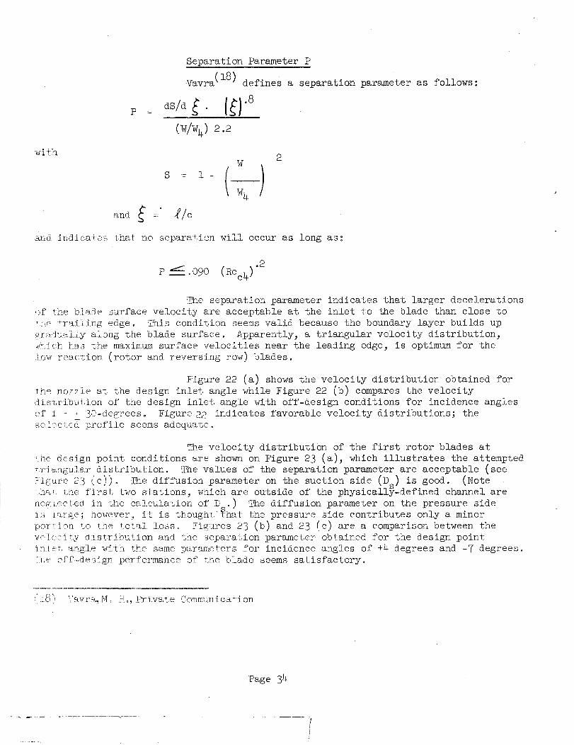
Separation Parameter P
Vavra(18) defines a separation parameter as follows:
I '1(wlw4) 2.2
wi:th2
,_W
S := i - (_.-_---I
_ w4 /
and " .Uo
and iadi.c,ate._,_; t,i_s,t; n.o sepa,ra+,i.o:n, will occur as long as_
.2
P_,090 (Rec4)
Tihe separation parameter indicates that larger decelerations
off tlhe blaJe surface velocity are acceptable at the inlet to the blade •than close to
'.he frai.l:i,ngedge° This condition seems valid because the boundary layer builds up
_.f_,J_.ally along tlhe blade surface. Apparently_ a triangular velocity distribution_
w(,.:iclhhas the max:imum surface velocities near the leading edge_ is optimum for the
i.ow reaction (rotor and reversing row) blades.
N:igure 22 (a.) shows the velocity distribution obtained for
t:he nozzle at the design inlet angle while Figure 22 (b) compares the velocity
disbrfbdtion of the design inlet angle with off-design conditions for incidence angles
of :i = + 30-degrees. Figure22 indicates favorable velocity distributions; the
selected _rcfil.e seems adeqaate.
The velocity distribution of the first rotor blades at
_he design point conditions are shown on Figure 23 (a), which illustrates the attempted
tr_angu]oar distribution. The values of the separation parameter are acceptable (see
Figure 23 (c)), :l_e diffusion parameter on the suction side (D) is good. (Note
...m....the first t_o stations, which are outside of the physically-defined channel are
rJ.e_._.ectedin the calculation of D .) The diffusion parameber on the pressure side. S
is !arge; however_ it is thought:_.hat the pressure side contributes only a minor
portion, to the <otal losso Figures 23 (b) and 23 (c) are a comparison between the
veilecity d:Lstribution and the separation parameter obtained for the design point
inlet, ao.gle with the same parameters .for incidence angles of +4. degrees and -7 degrees.
Axe effl..design performance of the blade seems satisfactory.
:'.L._"_ '(avr% M o IHo, Priva, te rjomm_a_nicaf.ion
Page 34

Figure 22. Velocity Distribution for Nozzle, 43 Vanes
Page 35

Figure 23. Velocity Distribution and Separation Parameter for
First Rotor, 98 Blades
Page 36

The velocity distribution for _ 13 = 71-degrees in
Figure 23 (b) (Method Vavra) closely resembles the one at the hub of Figure 23 !e)
(Met.hod NASA)° The acceptable separation parameters for the velocity di.stributiom
of Figure 23 (b) _ 3 =_71, indicates that velocity distributions according toFigure 23 (a) are acceptable even if the first two points were not neglected°
The velocity distributions for the reversing vanes
(93. blades) and second rotor blades (88 blades) are shown on Figures 24 and 25,
respectively° Again, the total diffusion factor i.s somewhat high because of a
large contribution from the pressure side. The suction s_.de is satisfactory and
the profiles seem adequate.
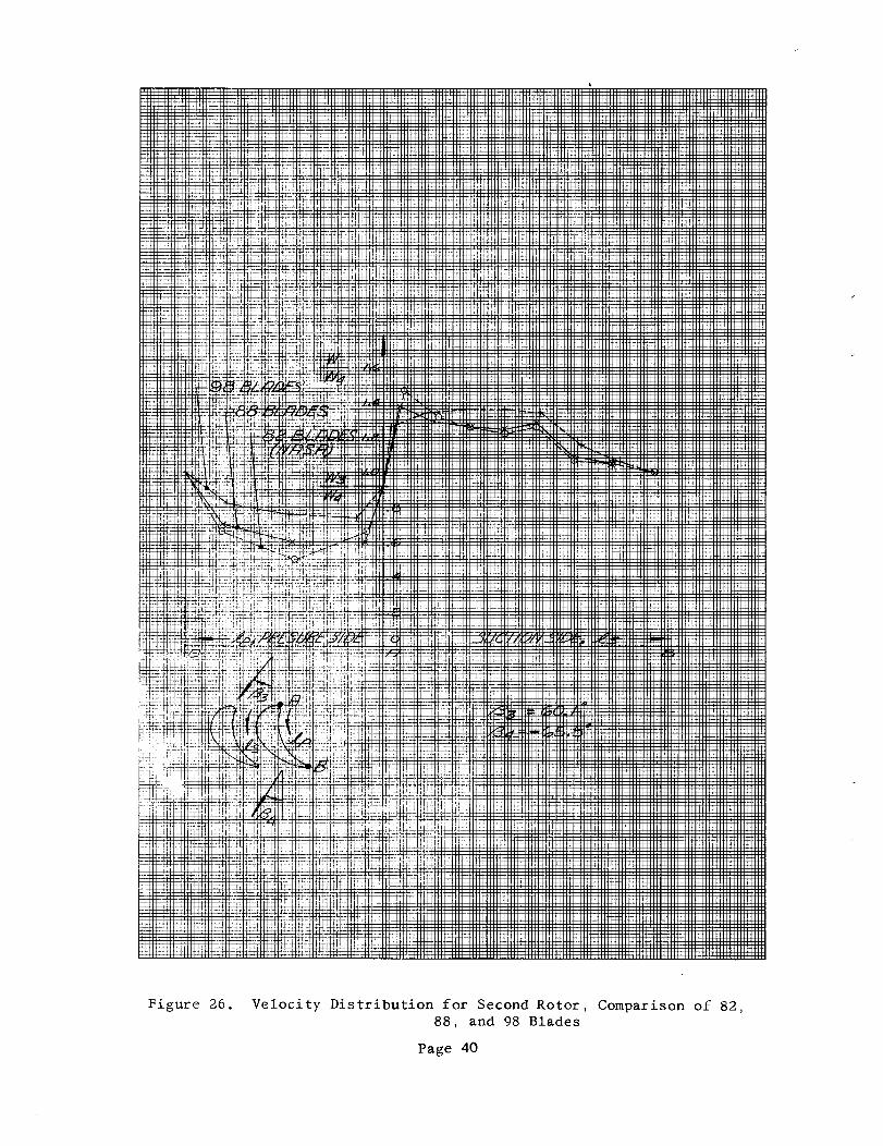
For the second rotor, the effect of the solidity upon
_he velocity distribution was investigated for 95_ 88_ arld $2 blades (see Figure 26]!,
The originally selected ao.lidi1y ($8 blades) proved to
be too iow; therefore, the number of blades for the reverb, fag r'cw a_d the second
rotor was increased to 97 and 94 blades, respecti.vely_.
Page 37
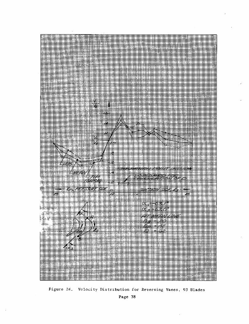
Pigure 24. Velocity Distribution for Reversing Vanes, 93 Blades
Page 38

6£ _d
_P_T_ _ '_o_o_ puog_ S _o 3 UOT_nqT_T_ Z_T_OI_A -g_ _n_T_
111111 III
iiiiiiiii
iJiilliii
ti_iiiiiill
IIIIIIIIIIIIII
hL_H-_H4¢fH+H+H-P+HIIIIIIIII_III¢t_t_ttt_
4+ ftLtH4_t444_44
_.'_._ ,TI; _
NT_
_4_N
_tfF_t_
7_7.:!T_ !!"Ir_
.i.iti#izc4-i7_,_11
4444444-ttL_t#
-H+_-H-H+_-
iiiiii',iiiii',
il!!!!!!
illi!!!!
H44 _44
_÷-_
:4it
-'.¢t_,i- 7-r_:;
:!:t ±ii_
_/_ .....
_i !r::!
2g_
r_-N]
.N_-I
_cct
I',II
Figure 26. Velocity Distribution for Second Rotor,
88, and 98 Blades
Page 40
Comparison of 82,

BIBLIOGRAPHY
o
o
o
o
6_
o
e
o
10
1.2 o
Ainley, D. G. and Mathieson, G. C. R., A Method of Performance Estimation
for Axial-Flow Turbines, R&M 2974, December 1951
Flugel, Gustav, Die Dampfturbinen_ ihre Berechnung und Konstruktion mit
einem Anhang uber die Gasturbinen, Johann Ambrosius Barth, Leipzig, 1931
Kofskey_ M. G., Cold-Air Performance Evaluation of a Three-Stage Turbine
having a Blade-Jet Speed Ratio of o15_ Designed for a 100_O00-Pound_Thrust
Hydrogen-Oxygen Rocket Turbopump Application, _77_ NASA Lewis Research
Center_ Cleveiand_ Ohio
Loschge, A._ Konstruktionen aus dem Dampfturbinenbau_ Springer Verlag_
Berlin/Gottin_g, 1955
Markov_ N. M., Calculation of the Aerodynamic Characteristics of Turbine
Blading_ Associated Technical Services !nCo_ Glen Ridge_ New Jersey, 1958
Stenning, Alan H., Design of Turbines for High-Energy-Fuel_Low-Power-
Output Applications_ MIT Report NOo 79
Stinson_ W. Do, Turbine Computer Program, NASA-Aerojet Computer Job No. i009_
Aerojet-General Memorandum, 27 September 1962
Traupel_ Walter, Thermische Turbomaschinen, Erster Band, Springer Verlag,
Ber!in/Gottingen/H-eidelberg, 1958
Vavra, M. H., Analysis and Design of Modified 87-5 Turbine, AGLR _3,
April 1962o
Vavra, M. Ho, Aero_Thermodynamics and Flow in Turbomachines, John Wiley
& Sons Inco_ New York/London, 1960
Zappa, 0._ Plot of Gas Efflux Angle from Turbine Blade Cascade (Private
Communicatio-_) based upon:
Dunavant, J. C. and Erwin, J. R., Investigation of a
Related Series of Turbine Blade Profiles in Cascade,
NASA TN 3802, 1956
Dunavant_ J. C._ Cascade Investigation of a Related Series
of 6_Percent Thick Guide Vane Profiles and Design Chart_,
NACA TN 3959, 1.957
Page 4i


APPENDICES


APPENDIXA
m
NOMENCIATURE

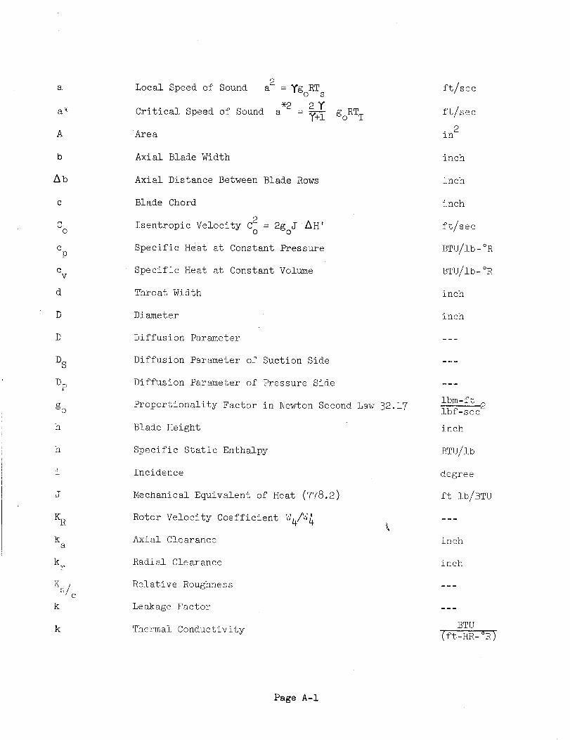
a
a _
A
b
Ab
C
Co
eP
Cv
d
D
D
D S
Dp
go
h
h
i
J
KR
ka
kr
K_/c
k
k
Local Speed of Sound
*2Critical Speed of Sound a
Area
Axial Blade Width
2
a = _goRT s
2¥- _+i goRTT
Axial Distance Between Blade Rows
Blade Chord
Isentropic Velocity C2o = 2goJ _H'
Specific Heat at constant Pressure
Specific Heat at Constant Volume
Throat Width
Diameter
Diffusion Parameter
Diffusion Parameter of Suction Side
Diffusion Parameter of Pressure Side
Proportionality Factor in Newton Second Law 32.17
Blade Height
Specific Static Enthalpy
Incidence
Mechanical Equivalent of Heat (778.2)
Rotor Velocity Coefficient W4/W _
Axial Clearance
Radial Clearance
Relative Roughness
Leakage Factor
Thermal Conductivity
ft/sec
ft/sec
2in
inch
inch
inch
ft/sec
BTU/lb-°R
BTU/lb-°R
inch
inch
ibm-ft2
ibf-sec
inch
BTU/lb
degree
ft lb/BTU
inch
inch
BTU
(ft-HR-°R)
Page A-I

L
I,U
T_o
1
M
M
n
n
N
0/ F
}.
S
?F:
R
r
_e
c
k)n
RX
S
Length of Point on Blade Surface from Point A
on Suction Side
Length of Point on Blade Surface from Point A
on Pressure Side
Specific Work in Blading
Specific internal Work
Absolute Mach Number
Molecular Weight
Mach Number Relative to Rotor Blade
Mass Flow
Number of Blades in a Row
>_o!ytropic Exponent
Rotational Speed
Mass Ratio 0xidizer/Fuel
Separation Parameter
Static Pressure
Total Pressure
Total PrEssure Relative to Rotor Blade
Prandtl-Number
i P V2
2 gol-Dynamic Head.
Gas Constant
Radius
Reynolds Number
Reyr_olds Number based on Blade Chord
Peynoids Number based, on Hydraulic Diameter
T _ _T ,s2 s4
Degree of Reaction_ R =rrj I
x TTI - 4s
Blade _itch
inch
inch
BTU/LB m
BTU/LB m
]om/s ec
Nm_
rpm
psia
psia
psia
psi
ibf-ft
ibm-_
ft
inch
Page A-2

/
/
t
te
TB
TT
TS
TTR
U
V
W
(I
Y
A
<
_u
Hi
rap
n_n
Z
(alpha )
(beta)
(gamma)
(delta)
(delta)
(zeta)
(eta)
(zeta)
Maximum Blade Thickness
Trailing Edge Thickness
Effective Blade Temperature
Total Temperature
Static Temperature
Total Temperature Relative to Rotor Blade
Wheel, Velocity
Absolute Velocity
Velocity Relative to Rotor
Angle Between Axial Direction and Absolute
Gas Velocity
Angle Between Axial Direction and Relative
Gas Velocity
c
v
Deviation'
Prefix to Indicate Change
Loss Coefficient
Blading Efficiency, total to total
Blading Efficiency, total to static
Internal Efficiency_ total to total
Internal Efficiency, total to static
Turbine Efficiency Based on Total to StaticPressure Ratio
Mean Politropic Efficiency
Flow Efficiency in Nozzle Blading
Flow Efficiency in Rotor Blading
Stagger Angle
inch
inch
oR
°R
°R
oR
ft/sec
ft/sec
ft/sec
degrees
degrees
degrees
degrees
Page A-3

fr
(m_)
P (rho)
(sigma)
Camber Angle
Absolute Viscosity
._ °_e._smty
Blade Solidity = c/s
degrees
LBm/(HR- ft )
ibm/f t3
SUBSCRIRT. S
:L
2
3
4
d
h
m
t
u
x
Inlet Stator
Out.let Stator
!:elet Rotor
O_Ltle t Rotor
At Blade Throat
At Blade Root
At Mean Blade Height
At Blade Tip
Tangential Component
Axial Component
Subscript preceding a symbol indicates the number of the stage°
SUPERo CRIF_,
Attached, to temperature or enthalpy means value for isentropic
expansion°
Page A-4

NOI.L03_IC -_I'XV..... j
\
0k-0
CDkH
0o
CDZ
A
5
!
N?

APPENDIX B
ESTIMATING LOSSES IN A _TURBINE STAGE

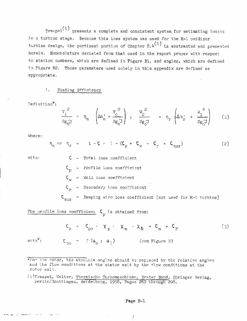
Traupel _lj#_ presents a complete and Consistent system for estimating losses
in a turbine stage. Because this loss system was used for the M-I oxidizer
turbine design, the pertinent portion of Chapter 8.4 (1) is abstracted and presented
herein. Nomenclature deviated from that used in the report proper with respect
to station numbers, which are defined in Figure BI, and angles, which are defined
in Figure B2. Those parameters .used solely in this appendix are defined as
appropriate.
i. Blading Efficiency
Deft niti on*:
2go_ - qn ah_ + 2go_/ _ 2gJ = qr Ah' + Wl2r 2go_
(1)
where:
_n or _r 1 -_ = + _ )i- (_p + _w + <r zus (2)
with:
zus
: Total loss coefficient
(p = Profile loss coefficient
= Wall loss coefficientw
: Secondary loss coefficientr
= Damping wire loss coefficient (not used for M-I turbine)
The profile loss coefficient _ is obtained from:P
with* :
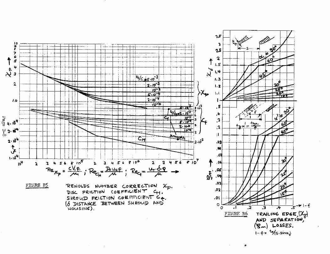
<p = <po " × p Xm
<po = f C_o ; _l)
X5 + _m + <F
from Figure B3
(3)
_F'or the rotor, the absolute angles should be replaced by the relative angles
and the flow conditions at the stator exit by the flow conditions at therotor exit.
(1)_raupel, Walter, Thermische Turbomaschinen, Erster Band, Springer Verlag,
iBerlin/Goettingen, Heidelberg, 1958, Pages 269 through 298.
Page B-I
!

IVI c Pl=
Xm : f (Vl/al)
; ks/c )from Figure B5
from Figure B4
x_ = f (1 - f) from Figure B6
= f (i - f) from Figure B6m
<F = f(hl%) fromFigure B7
The wall loss coefficient <w' which is due to the friction loss on
hub and tip annuli, is estimated as follows:
Sl sinai _b
_w = _po ×p h + Cf h. sin_1 7 (4)
The second term gives the loss due to gas friction in the gap between
stator and rotor. It usually is negligible.
For the secondary loss coefficient _ we set:r
r : _'l<ro + _s (5)
,_ V I sina I
w_+h_ _ro = f (_l - UI )
Xl/Xp = f (c/h)
<s : f (hs/h)
from Figure B8**
from Figure B9
from Figure BIO
(not applicable for present design)
*See footnote on Page B1.
_In Figure B8 the band for _ro : f (_) was extrapolated. The band was
assumed to become horizontal, similar to the loss coefficients given in
VAVBA.
Page B-2

The dampening wire loss coefficientzus
is obtained from:
cw sin<( )
4d
Dd . d
2 2
Dt - Dh
C = 1.2 - 2.4w
c - ._ - o8w
(6)
2. Velocity Triangle Efficiency
and K ( q = K 2) known, the velocity triangleWith q n and qr or K n r
can be calculated and with it the velocity triangle efficiencies:
= Ah/Ah' Static to staticsu 2
V° - V2 2Ah+
Lu 2go'D:: = Total to total
qu 2 2V° - V2 2 Vo - V2 2
Ah' + A h' +2god 2goO
* Lu
u : ah' + Vo2/2g#
2 V2 2V ° -Ah+
2goU
Ah' + Vo2/2go U
Total to static
(7)
(8)
(9)
3o Stage Efficiency
The internal or stage efficiencies are defined as, follows:
*See footnote on Page _i.
Page B-3
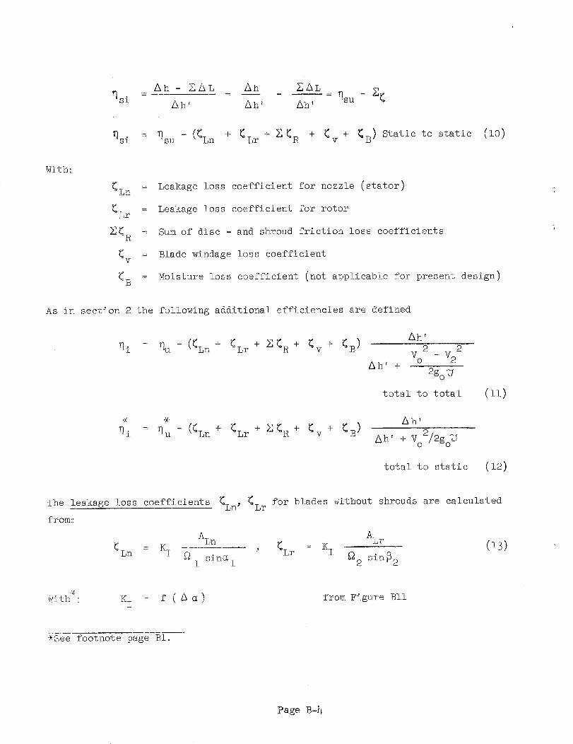
Ah - ZAL _ Ah EAL : qsu - g<_]si : Ah' Ah v Ah'
_si : _su - ((Ln + (Lr + _'<R + (v + (B) Static to static (i0)
Witht
<Lr
Ln = Leakage loss coefficient for nozzle (stator)
= Leakage loss coefficient for rotor
Sum of disc - and shroud friction loss coefficients
=: Blade windage loss coefficientv
Moisture loss coefficient (not applicable for present design)
As in section 2 the following additional efficiencies are defined
"qi : _]U - ((Ln + <Lr + X_R + _v + _
Ah'
B ) 2
Ah' +V° - V2 2
2go_
total to total (ii)
* _ Ah'
: _u - -(<Ln + <Lr + _]<R + < + <B )-i v Ah'+ Vo2/2go
total to static (12)
-The leakage loss coefficients (Ln' <Lr for blades without shrouds are calculated
from:
_Ln KI ALn ALr= _ _Lr : K I (13)
_i sin_l _2 sin_2
With : K I = f ( a _ ) from Figure :BI.I
'_See footnote page BI.
Page B_L

AL = Leakage area (ALn, nozzle; ALr, rotor)
= Annulus area=?rDh
and for blades with shrouds from:
KII ALn KII
- _-- ; _Lr -_Ln _JZn r
With*:
Z = Number of laybrinths
g = arc of admission
ALr
_2 sin _2
KII = f (ah'/Vl2/2gofi]) from Figure BI2
The loss coefficients _ for disc - and shroud friction are expressed by equationsR
(15) and (16).
<__ 2._4 cM (%/I)m)4 (Dh/h) (Disc) (l_)
Cf (Dt/Dm)4 (b/h)
<R : _ (Shroud) (16)
With :Dh%P
CM : f (Recto
V_ X _
U
m
U2 g_2 P2
= ah'/(U2/2go _ )
Cf =: f (_eofut_ p
) from Figure B5
) from Figure B5
*See footnote page BI.
Page B-5

The blade windage loss coefficient _v can be calculated from equation (17)
I -e .30 Zb b
<v = C +
With_
c : .04 + .52 h/Dm
c = .o19+ 1.1 (.iS5 - h/Dm)e
C = .88 - 13 (h/Dm) 2
C = .02 + 3.0 (.125 - h/Din) 2
Z_ :
(17)
blades free, upstream
I
blades covered, upstream
blades free, downstream
blades covered downstream
number of admission segments which
result in the total admission g .
Make if possible Zb = i.
Frequently it is convenient to calculate the power loss due to friction (NR) or
ventilation (Nv) , rather than the loss coefficient _R or _v"
_R = 4 cM p__m3 (Dh/_)3Dh2 (18)go
3Nv - 2 c (1-_) p Dm h _m (19)
go
The moisture losses being negligible in the present application are not discussed
further.
According to Ref. 3 the loss system described above is applicable to
subsonic turbines having blades of the general shape of Figure BI with a solidity
according to Figure B2.® @
<< <%ROTOR
®NOZZLE
lIJ
<<
FIGURE BI
Page B-6

F IG[_E BI
2
_4ous_N¢).


an_a_ RASACR _764 D_mUSU_IOR L_
w. F. Dankhoff (_ Copies)NASA
Lewis Research Center
21000 Brcokpark RoadCleveland, Ohio _135
Mail Stop 500-_O5
J. A. Durioa (1 Copy)
Mail Stop 500-210
Patent Counsel (1 Copy)Mall Stop 77-1
Lewis Library (2 Copies)Mail Stop _-7
Lewis Technical Information
Divleion (I Copy)
Mall Stop 5-5
M. J. HartBnn (i Copy)
Mail Stop 5-9
W. L. Stewart (i Copy)
Mail Stop 5-9
J. C. Montgomel'y (i Copy)
Mail Stop 501-1 SNPO-C
Major E. H. Karalis (i Copy) AFSC Lialson Office
Mail Stop 4-1
Lewis Office of Reliability and
Quality Assurance (i Copy)
Mail Stop 500-203
NASA Representative (6 Copies)NASA Scientific and Technical
Information Facility
Box 5700
Bethesda, Maryland
Library (i Copy)NASA
Ames Research Center
Moffett Field, California 94035
Library (1 Copy)NASA
Flight Research CenterP. O. Box 273
F._.te_r4_; AF'B, California 93_3
Library (i Copy)
NASA
Goddard Space Flight Center
Greenbelt, Maryland 20771
Library (i Copy)RA_£
Langley Research Center
Langley Station
Hampton, Virginia 23365
Library (1 Copy)
NASA
Manned Spacecraft CanterHouston, Texas 77058
Library (i Copy)
NASA
George C. Marshall Space Fl_ht CenterHuntsville, Alabsma 3_12
Library (1 Copy)NASA
Western Operations
150 Pico Boulevard
Santa Monlca, California 90_0_
Library (I Copy)
Jet Propulsion Laboratory4800Oak GroveDrivePIJadena, California 91103
ao 0o Tischler (2 Copies)
NASA HeadquartersCode RP
Washington, D.
T.. Z. Ban_ (i Copy)
AeroJet-General CorporationLiquid Rocket OperationsNASA Plant Representative
Building 2001, Room 53
Sacru--to, California 95809
J. W. Thomes, Jr. (5 Copies)
NASA
George C. Marshall Space FlightCenter I-E-E
Huntsville 0 Alabama
E. W. Gomersall (i Copy)
NASA
Mission Analysis DivisionOffice of Advanced Research and
TechnologyMoffett Field, California 94035
Dr° Keith Boyer (1 Copy)
Los £1smes Scientifis LaboratoryCMFo9P.O. Box 1663
Los A1asos, Rew Mexico
A. S_dt (i Copy)
Rational Bureau of Standar_
Cryoganic Division _
Boulder, Colorado
Dr. G. Wislicenua (I Copy)
Penn State University
Naval Ordinance Laboratory
University Park, Pl_nsylvauta
Dr. A. Acoeta (I Copy)
California Institute of Technolou
1201 East California Street
Pasad_, California
Dr. E. B. Konecci (i Cow)
Rational Aeronautics and _ce Council
Executive Office of the President
Ex_utive Office Building
Washington, V. C.
Dr. R. Vawra (I Copy)
Naval Pest Graduate School
Mooterey, California
R. V. Main (I Copy)
Air Force Rocket Propulsion LaboratoryEdvar_s Air Force Base
Edwar_, California
Dr. George Serovy (i Copy)
Iowa State UniversityAmes, Iowa
T. lura (I Copy)
Aeroopace Corporation
2400 East E1 Seg_mdo Blvd.
p. O. Box 95085LOS Angeles, California 900_5
REPORT NASA CR _4764 DISTRIBUTION LIST
(Continued)
F. Ghahnemani (I Copy)
Aerospace Corporation
2400 East E1 Segundo Blvd.
p. o. Box 95o85Los Angeles, California 90045
Chemical Propulsion Information Agency (i Copy)
Johns Hopkins University
Applied Physics Laboratory
8621 Georgia Avenue
Silver Spring, Maryland
Robert O. Bullock (i Copy)
Garrett Corporation
Airesearch Manufacturing Division402 S. 36th Street
Phoenix, Arizona 85034
Pratt and Whitney Aircraft Corporation
(I Copy)Florida Research and Development Center
P. O. Box 2691
West Palm Beach_ Florida 33402
Rocketdyne (Library Department
5_-_6) (i Copy)Division of North American Aviation
6633 Canoga AvenueCanoga Park, California 91304
John Stanitz (i Copy)
Thompson-Ramo-Wooldridge, Inc.
23555 Euclid Avenue
Cleveland, Ohio 44117
Dr. M. J. Zucrow (i Copy)
Purdue University
Lafayette, Indiana 47907