parameters identification for wood material (*mat 143) and ... · kuma and associates, tamedia...
TRANSCRIPT

16th International LS-DYNA® Users Conference Constitutive Modeling
June 10-11, 2020 1
Parameters Identification for Wood Material (*MAT_143) and its
Application on the Modeling of a Typical Timber Nuki Joint
Benshun Shao1, Nicolette Lewis2, Aliz Fischer1, Yuli Huang1, Francois Lancelot1 1 Arup, Advanced Technology & Research, San Francisco, USA
2 University of Washington, USA
Abstract Understanding the mechanical properties of the timber joint is a crucial aspect of modern wood construction. Numerical simulation of timber joints can provide valuable insights. However, due to the anisotropic nature of the wood, the sensitivity to local sliding and contact effects, the stiffness and strength modelling of timber joint connections is complex. This study explores the capability of the wood material formulation (*MAT_143/*MAT_WOOD) in LS-DYNA® for simulating the bending behavior of a typical Japanese carpentry connection, the Nuki joint. The material parameters identification was first conducted based on various experimental data. To provide robust results in an efficient manner, the usage of LS-OPT® was explored in this process. A 3-D Nuki joint model was then constructed and its bending behavior was compared with the experimental measurements. Sensitivity studies were conducted on the key contact modeling parameters in LS-DYNA. The study describes an efficient workflow for calibrating the wood material parameters. It also discusses the challenges involved in the modeling of timber joinery mechanics in LS-DYNA and offers suggestions for future research on this topic. Key words: Timber Nuki joint, wood material parameters identification; LS-OPT; sensitivity study
Introduction
Timber construction has been reviving in the past few decades due to a growing awareness of material benefits with respect to their environmental footprint [1]. Furthermore, the use of joinery connections may offer new benefits in construction assembly speed and sustainable non-destructive disassembly of timber structures, as historic precedents such as the Ise Shrines demonstrate [2]. Along the timber construction, the use of traditional joinery connections is also revitalizing. Examples such as Yusuhara Bridge Museum (Japan, 2010) by Kengo Kuma and Associates, Tamedia Office Building (Switzerland, 2013) by Shigeru Ban Architects, and the Writers Theatre (USA, 2016) by Studio Gang Architects feature 21st-century joinery connections.
While there are benefits to reintroducing joinery connections into modern construction from the perspectives of sustainability, constructability, and fabrication capabilities, the main obstacle is to characterize and codify the mechanics of these connections. To achieve this, while experimental efforts are needed to gain a better understanding of the wood structure behavior, numerical simulation is essential to economically generalize that knowledge to the multiple variations of connections.
Figure 1. Nuki joint, a simple joinery connection studied in this work.

16th International LS-DYNA® Users Conference Constitutive Modeling
June 10-11, 2020 2
Numerical studies of similar joints have been conducted in the past, mostly using the ABAQUS and ANSYS software packages [3] [4] [5] [6] [7]. In this paper, the capability of using wood material formulation *MAT_143 (*MAT_WOOD) in LS-DYNA to simulate the bending behavior of a typical Nuki joint has been investigated. Material parameter identifications have been first conducted based on various experimental measurements. Recommendations have been provided on the calibration process of the *MAT_143 material model. The benefits of using LS-OPT as an automatic material identification procedure have been briefly evaluated against manual process. Using these calibrated material parameters, a 3-D Finite Element (FE) model of the Nuki joint has been constructed in LS-DYNA. Simulation results have been compared with the experimental data. Sensitivity studies have been conducted on several contact modeling parameters. Finally, the challenges and limitations of modeling the wood joint mechanism using our method have been discussed.
Material parameters identification
In this section, the wood material parameters identification process for *MAT_143 is highlighted. Multiple material parameters of *MAT_143 have been determined based on experimental results.
Description of the wood material model (*MAT_143)
Wood is generally considered as an orthotropic material with different properties in longitudinal, tangential and radial directions. The material model *MAT_143 in LS-DYNA is transversely isotropic; The properties in the tangential and radial directions are assumed to be the same [1]. Distinct nonlinear behaviors can be defined in the directions parallel and perpendicular to the grain, for compression, tension and shear. The material has failure capability in tension and shear, but there are no failure criteria for compressive loadings.
For the modeling of the Nuki joint considered in the study, the compression and tension stress-strain characteristics are critical. These are controlled by elastic modulus, yield stress and post yield behavior in both along and perpendicular to the grain directions. The key material parameters considered in this study are summarized in Table 1 below.
For *MAT_143 model, the along and perpendicular to the grain directions can be defined with different options of the parameter AOPT on the material card [1]. In the study, the two directions are defined via the material axes, which rotate with the FE mesh when deformation occurs in the simulation.
Material parameter identification (*MAT_143)
*MAT_143 has generic parameters for Southern yellow pine (PINE) and Douglas fir (FIR). However, the mechanical properties of wood have large variations even within the same cultivar. For this specific study, the material parameters have been calibrated based on the physical testing of actual wood samples. As the *MAT_143 material model has orthotropic characteristics, multiple test setups are required to calibrate all its parameters. The series of experimental tests that has been performed is summarized in Table 1. Independent calibration processes have been conducted for specific groups of material parameters. Detailed FE models that accurately replicate the experimental conditions have been used to identify the best material parameter values to match the results of each test.
16th International LS-DYNA® Users Conference Constitutive Modeling
June 10-11, 2020 3
Test Material parameters calibrated
Compression test along grain
direction
Parallel elastic
modulus, EL
Parallel compression strength, XC
Parallel hardening initiation, NPAR
Parallel hardening rate,
CPAR Compression test in perpendicular-to-
grain direction
Perpendicular elastic
modulus, ET
Perpendicular compression strength, YC
Perpendicular hardening
initiation, NPER
Perpendicular hardening rate,
CPER Three-point bending
test along grain direction
Tension capacity along the grain, XT
Fracture energy in tension along the grain, GF1_PAR
Table 1 - Key material properties for *MAT143
Compression test in direction along the grain
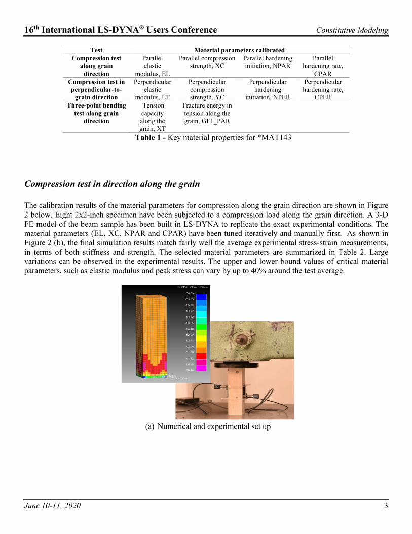
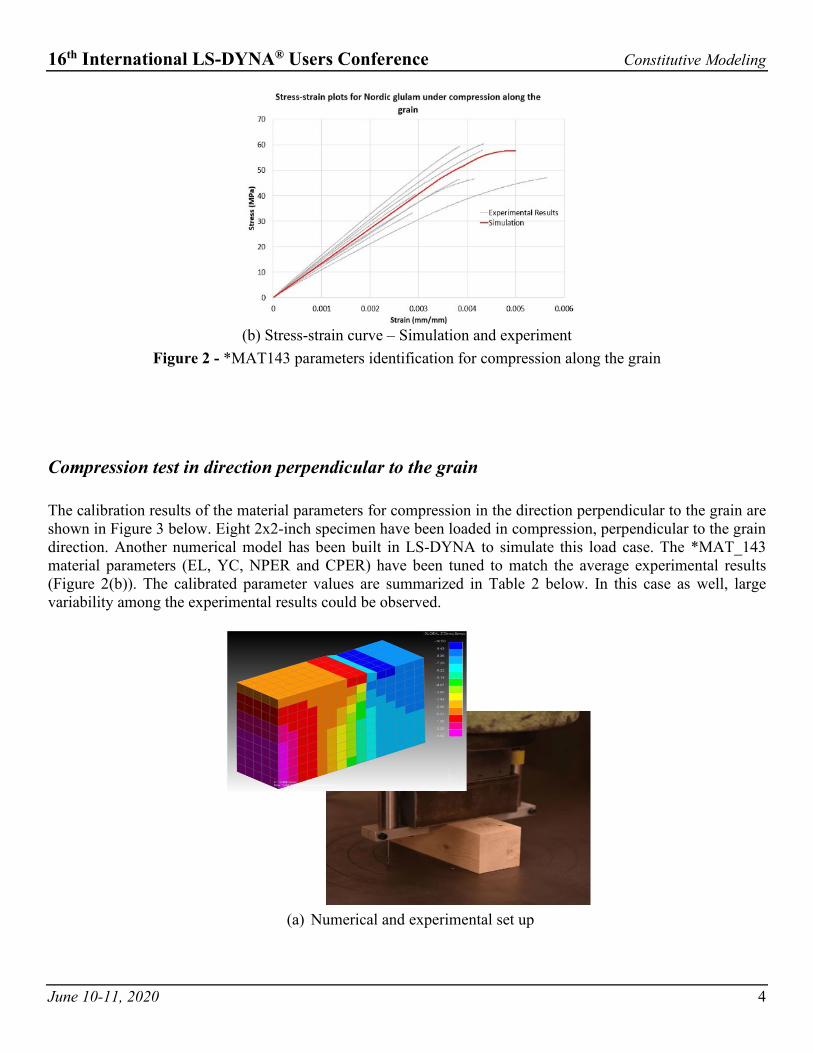
The calibration results of the material parameters for compression along the grain direction are shown in Figure 2 below. Eight 2x2-inch specimen have been subjected to a compression load along the grain direction. A 3-D FE model of the beam sample has been built in LS-DYNA to replicate the exact experimental conditions. The material parameters (EL, XC, NPAR and CPAR) have been tuned iteratively and manually first. As shown in Figure 2 (b), the final simulation results match fairly well the average experimental stress-strain measurements, in terms of both stiffness and strength. The selected material parameters are summarized in Table 2. Large variations can be observed in the experimental results. The upper and lower bound values of critical material parameters, such as elastic modulus and peak stress can vary by up to 40% around the test average.
(a) Numerical and experimental set up
16th International LS-DYNA® Users Conference Constitutive Modeling
June 10-11, 2020 4
(b) Stress-strain curve – Simulation and experiment
Figure 2 - *MAT143 parameters identification for compression along the grain
Compression test in direction perpendicular to the grain
The calibration results of the material parameters for compression in the direction perpendicular to the grain are shown in Figure 3 below. Eight 2x2-inch specimen have been loaded in compression, perpendicular to the grain direction. Another numerical model has been built in LS-DYNA to simulate this load case. The *MAT_143 material parameters (EL, YC, NPER and CPER) have been tuned to match the average experimental results (Figure 2(b)). The calibrated parameter values are summarized in Table 2 below. In this case as well, large variability among the experimental results could be observed.
(a) Numerical and experimental set up

16th International LS-DYNA® Users Conference Constitutive Modeling
June 10-11, 2020 5
(b) Stress-strain curve – Simulation and experiment
Figure 3 - *MAT_143 parameters identification for compression perpendicular to the grain
Bending test along the grain direction
The calibration of the tension parameters in the grain direction has been based on a 3-point bending test (Figure 4). Eight 1x1x20 inch simply supported specimen have been subjected to a point load at mid-span. These tests have been used to determine the tension capacity and the fracture energy. Figure 4(b) shows the load vs. vertical deflection results. The calibrated FE model’s response matches well the average experimental results in terms of stiffness, strength and brittle failure behavior. Large variations in tension strength and elastic modulus could again be observed from the experimental measurements. The selected parameters for *MAT_143, average (Ave.), lower bound (LB) and upper bound (UB), are summarized in Table 2.
(a) Numerical and experimental set up

16th International LS-DYNA® Users Conference Constitutive Modeling
June 10-11, 2020 6
(b) Load-displacement curve – Simulation and experiment
Figure 4 - *MAT_143 parameters identification using 3-point bending test
EL [MPa]
ET [MPa]
XC [MPa]
YC [MPa]
XT [MPa]
GF1_PAR [MPa mm]
NPER CPER NPAR CPAR
Ave. 13521 385 60 9.5 90.0 22.0 0.4 100.0 0.3 500.0 LB 10010 295 48 7.0 80
UB 15900 590 70 14 100 Table 2 - Calibrated material parameters - *MAT_143 model – Nuki joint analysis
Use of LS-OPT for material parameters identification
In the parameter identification process presented above, matching numerical simulation to experimental results has been achieved manually and iteratively. Although this approach yields a reasonably good match across various load cases, it is empirical, time consuming and may not correspond to the optimum solution. Especially when multiple parameters are to be determined simultaneously and the process repeated for different loadcases.
The capabilities of the optimization package LS-OPT for the calibration of the compression test in the direction perpendicular to the grain - simultaneous identification of perpendicular normal modulus (ET), perpendicular compression strength (YC), perpendicular hardening initiation (NPER) and perpendicular hardening rate (CPER) – have also been explored. Figure 5 below illustrates the adopted process. A Mean Square Error composite objective was defined to minimize the difference between the simulation stress-strain curves and the filtered experimental data.

16th International LS-DYNA® Users Conference Constitutive Modeling
June 10-11, 2020 7
Figure 5 - LS-OPT application – Parameter optimization for perpendicular compression test
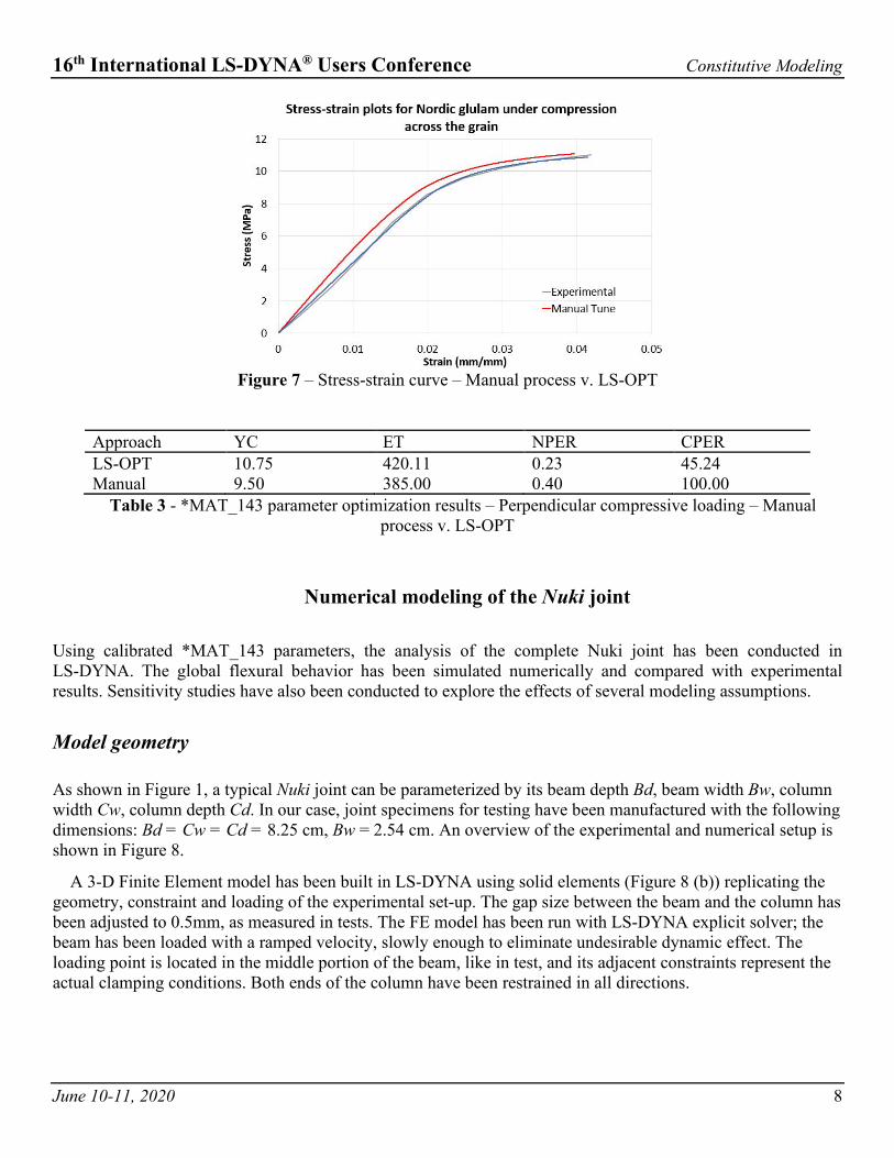
The optimization results using LS-OPT are summarized in Figure 6 and Table 3. The optimization is fast, taking only 3 iterations to converge to a set of parameters within tolerance. The material parameters obtained by LS-OPT method and the values derived manually by trial and error are different. And for this particular case, the LS-OPT-calibrated FE models show a better match with tests as illustrated in Figure 7. However, as mentioned previously, wood material properties have large variability. Matching results to a specific test specimen and for a single load case will not necessarily lead to the best calibration for more complex situations.
(a) Vertical stress-strain curve for each trial
(b) Objective function value for various parameters
Figure 6 - Optimization results for the perpendicular compressive material parameters from LS-OPT
16th International LS-DYNA® Users Conference Constitutive Modeling
June 10-11, 2020 8
Figure 7 – Stress-strain curve – Manual process v. LS-OPT
Approach YC ET NPER CPER LS-OPT 10.75 420.11 0.23 45.24 Manual 9.50 385.00 0.40 100.00
Table 3 - *MAT_143 parameter optimization results – Perpendicular compressive loading – Manual process v. LS-OPT
Numerical modeling of the Nuki joint
Using calibrated *MAT_143 parameters, the analysis of the complete Nuki joint has been conducted in LS-DYNA. The global flexural behavior has been simulated numerically and compared with experimental results. Sensitivity studies have also been conducted to explore the effects of several modeling assumptions.
Model geometry
As shown in Figure 1, a typical Nuki joint can be parameterized by its beam depth Bd, beam width Bw, column width Cw, column depth Cd. In our case, joint specimens for testing have been manufactured with the following dimensions: Bd = Cw = Cd = 8.25 cm, Bw = 2.54 cm. An overview of the experimental and numerical setup is shown in Figure 8.
A 3-D Finite Element model has been built in LS-DYNA using solid elements (Figure 8 (b)) replicating the geometry, constraint and loading of the experimental set-up. The gap size between the beam and the column has been adjusted to 0.5mm, as measured in tests. The FE model has been run with LS-DYNA explicit solver; the beam has been loaded with a ramped velocity, slowly enough to eliminate undesirable dynamic effect. The loading point is located in the middle portion of the beam, like in test, and its adjacent constraints represent the actual clamping conditions. Both ends of the column have been restrained in all directions.

16th International LS-DYNA® Users Conference Constitutive Modeling
June 10-11, 2020 9
(a) Experimental set up of Nuki joint loading
(b) Numerical model of the Nuki joint
Figure 8 - Set up of experimental specimen and numerical model in LS-DYNA
Other modelling parameters
- Hourglass control: to eliminate possible hourglassing effects due to the large deformation at contact locations, fully integrated solid elements (TYPE 2) have been adopted.
- Contact definition: an automatic two-way surface-to-surface contact (*CONTACT_AUTOMATIC_SURFACE_TO_SURFACE) has been defined between the beams to represent the interaction at the joint slot. The default penalty-based method has been first considered. Contact parameters proved to affect load-deflection results significantly. Various contact friction coefficients as well as contact types have been investigated and will be discussed in detail.
- Element size: cuboid elements of about 4 mm (10 to 20 elements across the beam width) have been used, based on preliminary sensitivity study considering results convergence v. computational cost.
- Damping: A 20% damping coefficient (*DAMPING_FREQUENCY_RANGE_DEFORM) has been applied to the model to reduce further any dynamic effect.

16th International LS-DYNA® Users Conference Constitutive Modeling
June 10-11, 2020 10
Results and sensitivity study
General global behavior
The general deformation and stress distribution from the LS-DYNA simulation is show in Figure 9. Compression stress concentrations occur at the two contact locations at the top and bottom edges of the joint area. Tensile stresses develop on the back side of the loading beam. The LS-DYNA simulations and physical tests have been exhibiting similar behavior.
(a) Stress distribution in loading beam
(b) Close-up deformation and stress contour – Simulation and experiment
Figure 9 - Behavior of the wood joint – LS-DYNA analysis
The moment-rotation characteristics for the Nuki joint derived from the simulation and experimental measurements are shown in Figure 10. Both the lower bound and upper bound results are shown to illustrate test and simulation results variability. The lower bound simulation results match the average experimental results reasonably well in terms of bending stiffness and bending strength. However, the simulation models have exhibited a stiffer behavior compared to the experiments in general. There can several possible reasons for these discrepancies:
- The local stress concentration and progressive material failure could not be captured very accurately given the current *MAT_143 model’s limitations. *MAT_143 compression properties do not include any strength degradation and deformation and local damage may be underestimated. The roughness of wood material surface wound adds a soft layer especially at the joint contact edges, and this softening could not be represented with the current model.
- Some sliding between the beams is suspected to occur in the tests, which might have induced larger displacements. With the test instrumentation available, any local sliding is difficult to quantify and could not be rigorously accounted for in the simulation model. To explore the effect of various modeling assumptions, sensitivity analyses have been performed and their outcomes are briefly discussed below.

16th International LS-DYNA® Users Conference Constitutive Modeling
June 10-11, 2020 11
Figure 10 - Moment-rotation characteristics of the Nuki joint – Lower and upper bound properties – Simulation
and experiment
Effect of contact parameters
In general, for steel and concrete joints, the Moment-Rotation characteristics mostly depend on the connection members’ section and material properties. However, we suspect that the Nuki wood joint is behaving more like a mechanism where the compliance of the interface between the two wood pieces might significantly affect the response. Sensitivity studies have been conducted on several contact parameters in LS-DYNA to understand the impact of these modeling assumptions on the global assembly response.
Contact types
The default penalty-based contact formulation is node-based (with contact parameter SOFT=1), a restoring force is applied to the slave nodes when they penetrate a master segment. However, as the meshes of the beam and column do not align perfectly, at the edges of the interaction zone, residual penetration has been observed in the FE models, as shown in Figure 11 (a). This could be improved by assigning SOFT=2 to switch to a segment-based method, as shown in Figure 11 (b). However, the global Nuki assembly responses are almost identical for the two contact options, as illustrated in Figure 12. Local contact penetration proved to have a very limited effect on the overall results.
(a) Response using SOFT=1 (b) Response using SOFT=2
Figure 11 – Beam interface deformation with different contact modeling options

16th International LS-DYNA® Users Conference Constitutive Modeling
June 10-11, 2020 12
Figure 12 - Moment-rotation characteristics of the Nuki joint– Different contact types
Effect of contact stiffness
The normal contact stiffness is calculated from element bulk modulus and the contact segment area. Penalty factors on the contact cards are available to adjust the stiffness of both slave and master sides in LS-DYNA. However, applying scaling factors of 1.0, 5.0 and 10.0, proved to have a limited effect on the global response of the Nuki joint. The overall assembly deformation and the Moment-Rotation characteristics for these three cases are shown in Figures 13 and 14 respectively.
Figure 13 - Beam deflections with different contact stiffness factors (5x amplification)

16th International LS-DYNA® Users Conference Constitutive Modeling
June 10-11, 2020 13
Figure 14 - Moment-rotation characteristics of the Nuki joint – Different contact stiffness factors
Effect of contact friction coefficient
Besides the normal stiffness of the contact, as the loading beam deflects, a significant tangential contact force is generated. This tangential component is affected by the friction coefficient between the two surfaces. To investigate the effect of friction on the Nuki joint behavior, static friction coefficients of 1%, 30% and 60% have been applied to the model. The tangential contact force as well as the assembly moment-rotation relationships for these different cases are shown in Figure 16. The beam deflections are also shown in Figure 15. The friction coefficients significantly affect the global behavior of the joint. Larger friction coefficients result in a much stiffer behavior and reduced deformations.
Figure 15 - Beam deflections with different contact friction coefficients (5x amplification)

16th International LS-DYNA® Users Conference Constitutive Modeling
June 10-11, 2020 14
(a) Moment-rotation characteristics
(b) Tangential friction force v. beam loading
Figure 16 - Moment-rotation characteristics and contact forces for the Nuki joint – Different friction coefficients
Summary
After the calibration of the *MAT_143 model parameters, the simulation of a Nuki joint has been performed in LS-DYNA and compared with test results. The analysis results match reasonably well the experimental measurements in terms of both stiffness and strength when lower bound material parameters have been applied to the FE model. However, variations in material properties are significant and the simulation models generally exhibit a stiffer behavior than test specimen. Sensitivity to other modelling parameters has also been investigated: the simulation results of the Nuki joint are not significantly affected by local contact penetrations or contact stiffness definition. However, change in contact friction – and tangential force amplitudes at the beam interface – have a significant impact on the overall joint Moment-Rotation characteristics.
16th International LS-DYNA® Users Conference Constitutive Modeling
June 10-11, 2020 15
Conclusions
In the study, the capability of the wood material formulation *MAT_143 in LS-DYNA for modeling a typical Nuki joint has been assessed. Material *MAT_143 could successfully be calibrated against simple loading conditions such as compression and tension along and perpendicular to the grain directions. In this study, a material parameters identification process based on three independent testing results has been conducted. Subsets of *MAT_143 parameters were tuned based on each experimental measurement. Assuming the orthogonality characteristics of wood material, different groups of material parameters have been calibrated separately against specific experimental data. LS-OPT has been benchmarked in the material parameter identification phase especially when multiple parameters also needed to be tuned simultaneously and it proved to be a useful and efficient tool. LS-OPT results even appeared to be a better match for the perpendicular to the grain load case; however, as wood material exhibits significant variability, material calibration against a specific test curve – or a test average - might not lead to the best simulation results. It is recommended to consider a range of properties, for instance between lower and upper bounds, for the simulations as well. The numerical simulation results of the wood Nuki joint mechanism in LS-DYNA match the physical tests reasonably well considering the variability of the experimental results. However, the numerical models exhibit a generally stiffer behavior compared to the test specimen. Significant challenges identified for modeling the Nuki joint mechanism, beside material variability, include multi-axial stress state, contact friction and failure mechanism. Modelling improvement for the post yield behavior is needed especially under compression. Based on the sensitivity study results, contact friction affects the global joint stiffness significantly. More research is needed for improving the compression failure capabilities of the wood material model, and to represent more accurately the friction at the beam interface as well as the overall compliance of the Nuki assembly.
Acknowledgement This paper is building upon previous and ongoing collaboration between Arup, MIT, and EPFL [10] [11] [12]. The authors would like to acknowledge Demi Fang, Daniel K Landez, and Caitlin Mueller at MIT, who performed and led the physical testing, Jan Brütting and Corentin Fivet at EPFL for their input on wood material behavior, and Julieta Moradei and Nick Sherrow-Groves at Arup for coordinating this collaborative effort. Further acknowledgements for Nordic Structures and Bensonwood for providing the prototype material, Autodesk BUILD Space for the fabrication.
References
[1] Oliver C, Nassar N, Lippke B, McCarter J. Carbon, Fossil Fuel, and Biodiversity Mitigation with Wood and Forests. J. Sustain. For., 2014; 33(3): 248-275.
[2] Henrichsen C, Bauer R. Japan Culture of Wood: Buildings, Objects, Techniques, 1st edition. Boston: Birkhauser, 2004. [3] Guan Z, Kitamori A, Komatsu K. Experimental study and finite element modelling of Japanese “Nuki” joints - Part one: Initial
stress states subjected to different wedge configurations. Engineering Structures 2008; 30: 2032-2040. [4] Jeong G, Park M-J, Park J-S, Hwang K-H. Predicting load-carrying capacity of dovetail connections using the stochastic finite
element method. Wood and Fiber Science 2012; 44(4): 430-439. [5] Guan Z, Kitamori A, Komatsu K, Experimental study and finite element modelling of Japanese ‘Nuki’ joints — Part two:
Racking resistance subjected to different wedge configurations. Engineering Structures 2008; 30 (7): 2041–2049. [6] Chen C, Qiu H, Lu Y. Flexural behavior of timber dovetail mortise-tenon joints. Construction and Building Materials 2016;
112:366-377. [7] Li Y, Cao S, Xue J. Analysis on mechanical behavior of dovetail mortise-tenon joints with looseness in traditional timber
buildings. Structural Engineering and Mechanics 2016; 60(5): 903-921. [8] Federal Highway Administration. Manual for LS-DYNA Wood Material Model 143. US Department of Transportation,
McLean, Virginia, Manual FHWA-HRT-04-097, Aug. 2007.

16th International LS-DYNA® Users Conference Constitutive Modeling
June 10-11, 2020 16
[9] Livermore Software Technology Corporation (LSTC), LS-DYNA Keyword User’s Manual: Material Models, vol. 2. Livermore, California: Livermore Software Technology Corporation, 2018.
[10] Moradei J et al. Structural Characterization of Traditional Moment-Resisting Timber Joinery,” in Proceedings of the International Association for Shell and Spatial Structures (IASS) Symposium, Cambridge, MA, USA, 2018.
[11] Fang D, Brütting J, Moradei J, Fivet C, Mueller C. Rotational stiffness in timber joinery connections: analytical and experimental characterizations of the Nuki joint, presented at the 4th International Conference on Structures and Architecture, Lisbon, Portugal, 2019.
[12] Fang D, Moradei J, Brütting J, Fischer A, Landez D, Shao B, Sherrow-Groves N, Fivet C, Mueller C. Modern timber design approaches for traditional Japanese architecture: analytical, experimental, and numerical approaches for the Nuki joint. in Proceedings of the International Association for Shell and Spatial Structures (IASS) Symposium, Barcelona, Spain, 2019.