parameters influence on wrinkling in … influence on wrinkling in deep drawing ... the process has...
TRANSCRIPT
59
Nonconventional Technologies Review 2013 Romanian Association of Nonconventional Technologies Romania, September, 2013
PARAMETERS INFLUENCE ON WRINKLING IN DEEP DRAWING CYLINDRICAL CUPS
Pop Alin1, Mihaila Ioan2, Radu Ioan3, Blaga Florin3 1Universitatea din Oradea, [email protected] 3 Universitatea din Oradea, [email protected]
4 Universitatea din Oradea, [email protected]
ABSTRACT: The paper presents the influence of the main deep drawing process parameters on wrinkling. We study the effect of the parameters like punch radius, die radius and blank holder force. Is difficult to analyze witch of those factors has more influence on wrinkling growth. The best way to do this is to use the finite element method. It has been performed several simulations with different values of the factors. The process has been simulated in ABAQUS 3D software. KEY WORDS: deep drawing, finite element, die radius, wrinkling
1. INTRODUCTION
The deep drawing is a process very important in the cold pressure witch is used in many industries. As many sheet metal deformations processes, deep drawing can be described like a very complex operation in with the process parameters have a big influence. Those process are the punch and the die shape, blank shape, the blank holder force, the contact between element and material properties. Because each of those element has a separate influence in the process, is a not an easy task to find the best parameters values for the optimization of deep drawing process. In the last years it has been showed an ascending trend of the people involved in research studding the optimization process to this process. Being a process so important in the cold pressure, it’s use on a big scale in many other industrial domains, like auto industry.
It can be consider rational the shape of those pieces witch can be made by one single deep drawing operation. The number of successive operations depends by the report between the height of the part and the d diameter. When the part have a flange, the number of successive deep drawing steps is established by taking account the report between the diameter of the flange and the diameter of the part. 2. THE FINITE ELEMENT METHOD
The fundamental concept of the Finite Element Method divided a complex problem into many simple problems and it use complex mathematical formulas to join all the solutions of every simple problem such as it’s built a solution to the complex problem.
2.1 Model description
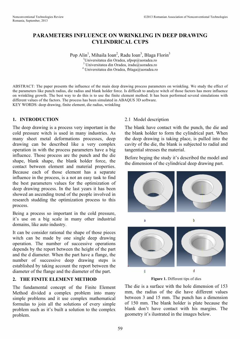
The blank have contact with the punch, the die and the blank holder to form the cylindrical part. When the deep drawing is taking place, is pulled into the cavity of the die, the blank is subjected to radial and tangential stresses the material. Before beging the study it’s described the model and the dimension of the cylindrical deep drawing part.
Figure 1. Different tips of dies
The die is a surface with the hole dimension of 153 mm, the radius of the die have different values between 3 and 15 mm. The punch has a dimension of 150 mm. The blank holder is plate because the blank don’t have contact with his margins. The geometry it’s ilustrated in the images below.

60
The simulations are made in Abaqus Explicit 3D. The geometry of the parts are made separately in the Abaqus self design environment.
Abaqus Explicit take into consideration the thickness of material when material and the rigid component have a contact between them. All the freedom degrees of the die are blocked. The blank holder can make a translation only in vertical direction so it can be able to have contact with the blank. We will apply a force of 20 KN to the blank holder. The friction coefficient between the punch and the blank is 0.1 and between the die and the blank is 0.01. The last research confirmed that the friction coefficient has an important role the deep drawing process.
Figure 2. Deep drawing parts assembly
The deep drawing simulation speed is constant equal with 2 mm/sec and the meshing is made so the the distance between nodes is less then the thinkness of the material. The computation time depends by the dimension of the mesh and the value of punch speed. So we will use an artificial speed in the simulate that it will be bigger then the physical speed. It could be possible to not have identical results if the simulation punch speed is increase to much. This process of growing artificial the speed is called mass scaling, and it was used to increase the punch speed so that properties of the materials were not modified. [1] 3. FINITE ELEMENT MODEL
The finite element analyze is a very efficent way to investigate the parametric infuence of deep drawing procces and the material response. It’s show very
useful information to establish corect the production procces functionality. This study is using for analyse the deep drawing cylindrical cups the finite element method . The punch displacement it was realise by using a referece nod that was associated to it. A reference nodes was associated with the die and the blank holder force. The punch, the die and the blank holder are defined to be rigid parts, and the blank is defined to be elastic plastic part.
The simulation deep drawing process has 2 steps. In the first step the blank holder force is apply to the blank and in the second step the punch is moved with a distance equal with the height cylindrical cup.
After the boundary conditions and the blank holder force were apply the simulation have been performed.
Figure 3. The path on the blank used to analyse
All the model geometrical dimensions can be modify with different values if is neccesary. The geometrical parameters are: - blank thickness 0.8 mm - punch diameter 150 mm - blank diameter - punch radius - die radius - punch travel.
Figure 4. Plastic equivalent deformation

61
The blank have a friction contact with three element. As we discribe previous the deep drawing simulation is made in two steps. In the second step the punch is moving with a constant speed on a distance and the blank holder force is stil active. The die has all the freedom degree blocked, the punch and the blank holder are free after a normal direction to the surface of the blank. The friction is one of the must important parameters in deep drawing, and it influence the material flow and the neccesary force for the deformation. In fact the friction coefficient has a double impact also positive and negative in the deep drawing process.
There are also numerous cases where the fiction is opposing material flow and there are cases where the materal flow is could be possible because of friction. To high value of the friction between die, blank holder and the blank it can happen a thinning of material over the limit. In case we are not using a lubricant it could appear signs of material damage. 4. SIMULATIONS AND RESULTS
The defects in deep drawing process can be classify in four big groups. All the defect belong to parts that are already done
- defects because of material thinning. - defects because of asimetric flow - defects of material surface - defects because of gemetrical distortion like wrinkling.
Those defects are avoided is the system is designed propertly The most defects in deep drawing process are fracture and the wrinkling.[2] In general the cracks apear in the walls subjected to compresion between the die and the punch. The wrinking apear in the flange of the part. As mch as the die cavity is deeper the risc to appear defect is major.
Figure 5. Deep drawing simulation
This section will try to make a corelation bettwen the die radius, punch radius with the wrinkling ocurrence. It has been taken diferente value of the radius die between 3 mm and 15 mm and for the punch radius values between 3 mm and 8 mm. .
Figure 6. Plastic equivalent deformation

62
For all this parametric variation it was made plastic deformation analysis in principal plane. It was made several simulation for different blank holder forces,
Figure 7. Results for radius punch 3 mm and radius die 3 mm
die radius and punch radius. With those results it was build the forming limit diagram.
Were performed a series of simulations with different values of radius punch, radius die and blank holder force. The values of the simulations were carried out for the die was 3 mm, 5 mm, 8 mm, 10 mm, that the radius punch were considered the values of 3 mm, 5 mm, 8 mm, and the blank holder force values were taken from 20 kN, 30 kN, 40 kN.
Taking into account the values obtained were made compared graphics by several criteria. At first was taken into account the influence radius die on
plastic deformations occur, implicit on wrinkling of flange part. Were considered different die radii in the range of 3 mm to 15 mm and a radius of 3 mm punch. Notice how to higher values of die radius the, plastic deformations are smaller both in the major direction and minor direction as well.
Figure 8. Plastic deformation results for different values of
die radius
The second factor analyzed in the wrinkling cylindrical parts study is the radius punch. We have done simulations with values of 3 mm, 5 mm, 8 mm.
Note that the punch radius don’t have an influence so big on plastic equivalent deformation values. However it is observed that at higher values of the radius the plastic equivalent deformation are decreasing.
Figure 9. Plastic deformation results for different values of punch radius
-0.1
0
0.1
0.2
0.3
0.4
0.5
-0.6 -0.5 -0.4 -0.3 -0.2 -0.1 0 0.1
Rp 3 mm Rd 3mm
-0.1
0
0.1
0.2
0.3
0.4
0.5
-0.6 -0.5 -0.4 -0.3 -0.2 -0.1 0 0.1
Rd 3 mm Rp 3 mm Rd 5 mm Rp 3 mm Rd 8 mm Rp 3 mm
Rd 10 mm Rp 3 mm Rd 15 mm Rp 3 mm
-0.1
0
0.1
0.2
0.3
0.4
0.5
0.6
-0.6 -0.5 -0.4 -0.3 -0.2 -0.1 0 0.1
Rd 3 mm Rp 3 mm Rd 3 mm Rp 8 mm Rd 3 mm Rp 8 mm

63
The last factor to consider in analyzing the phenomenon of wrinkling is the blank holder force witch is acting on the blank. It were considered the values of 20 KN, 30 KN and 40 KN. Blank holder force values don’t have a great influence in this case because of low coefficient of friction that was considered in the simulation.
Figure 10. Plastic deformation results for different values of
blank holder force
5. CONCLUSIONS
The defects based on material wrinkling are one of the major case of getting inappropriate deep drawing parts. It was study the influence of three parameters of deep drawing process. From the results it can be seen that the die radius has a major influence on wrinkling defects but we have to take in consideration that we used a value of 0.01 friction coefficient, this make the blank holder force to have
less in influence in deep drawing process. For the future works the friction coefficient can be increase so the blank holder force will have more importance. 6. REFERENCES 1. F. Ayari, E. Bayraktar - Parametric Finite
Element Analysis for a square cup deep drawing process Journal of Achievements in Materials and Manufacturing Engineering 2011
2. Mohammad Reza Morovvati & Afshin Fatemi &Mojtaba Sadighi Experimental and finite element investigation on wrinkling of circular single layer and two-layer sheet metals in deep drawing process Int J Adv Manuf Technol (2011)
3. A. Pourkamali Anaraki, M. Shahabizadeh, and B. BabaeeFinite Element Simulation of Multi-Stage Deep Drawing Processes & Comparison with Experimental Results World Academy of Science, Engineering and Technology 61 2012
4. Pop Alin, Grebenisan Gavril, Radu Ioan-Cylindrical parts stress study based on the bottom geometry shape, Annual Session of Scientific Papers “IMT Oradea- 2011”, Oradea, 2011.
5. A. Wifi, A. Mosallam - Some aspects of blank-holder force schemes in deep drawing process Journal of Achievements in Materials and Manufacturing Engineering.
Deformatii plastice pentru diferite valori ale fortei de retinere a semifabricatului
-0.1
0
0.1
0.2
0.3
0.4
0.5
0.6
-0.6 -0.5 -0.4 -0.3 -0.2 -0.1 0 0.1
20 KN30 KN40 KN