part no. m10478-a2 product specification sheet m10478.pdf · part no. m10478-a2 product...
TRANSCRIPT

Antennas for Wireless M2M ApplicationsProduct Specification 12MD-0050-2-PS
GPS RADIONOVA® RF Antenna Module Product SpecificationPart No. M10478-A2
DescriptionAntenova M2M’s GPS RADIONOVA® M10478-A2antenna module is an ultra compact single package solution that combines full GPS receiver and antennaon the same module. The M10478-A2 is a highlyintegrated GPS RF antenna module suitable forL1-band GPS systems. The device is based on the Mediatek MT3337 GPS architecture combined withAntenova's antenna technology. Using patented external matching means this module is suitable from small watch applications to large tracker devices.
All front-end and receiver components are contained in a single package laminate base module, providing a complete GPS receiver for optimum performance. The M10478-A2 operates on a versatile 2.8V-4.2V supply with low power consumption and severallow power modes for further power savings. An accurate 0.5ppm TXCO ensures short TTFF.Indoor and outdoor multi-path detection and compensation. Support multi-GNSS incl. QZSS, SBAS ranging.
Providing a true drop in solution with the antenna and RF in a single SMT package, GPS RADIONOVA® M10478-A2 offers ease of integration and shorter design cycles for faster time to market.
Package StyleSMD Castellated pads enable SMT placement and re flow as well as hand soldering. 13.8 x 9.5 x 1.8mm RF Antenna Module
Personal Navigation Devices (PNDs)
Portable Media Players (PMPs)
Personal Digital Assistants (PDAs)
•
•
•
Medical / eHealth
Smart Watches
Asset Tracking / Personal Safety
•
•
•
FeaturesEasy to use, low cost single package GPS RF antenna module
Mediatek MT3337 chip
Ultra small SMT package; 13.8 x 9.5 x 1.8mm
Low current consumption <200uA required for Periodic mode.
Novel external matching ensure easy tuning for each platform
AIC, Active Interference Cancellation for antiJamming.EPO (Extended Prediction Orbit), up to 30day orbit prediction, Warm TTF = <5sec
•
•
•
•
•
•
•
Functional Block Diagram
Applications
Top View Bottom View
External Matching
Circuit
1

Antennas for Wireless M2M Applications2
Product Specification 12MD-0050-2-PS
GPS RADIONOVA® RF Antenna ModulePart No. M10478-A2
Absolute Maximum RatingsSymbol Parameter Min Max UnitV
CCMain Supply Voltage -0.3 4.3 V
VIO
Supply voltage I/O ring -0.3 3.6 V
V VBCKP Supply -0.3 4.3 V
RFIN
Maximum RF Input Power N/A +10 dBm
TSTG
Storage Temperature -40 +85 °C
T A
Operating Temperature -40 +85 °C
* Exposure to absolute ratings may adversely affect reliability and may cause permanent damage.
Recommended Operating ConditionsSymbol Parameter Min Typ Max UnitV
CCMain Supply Voltage 2.8 3.3 4.3 V
VBATT
VBCKP Supply 2.8 3.3 4.3 V
TOP
Operating Temperature -40 -+85°C
.DC Electrical CharacteristicsConditions: V
CC = 3.3V, T
OP = 25 °C
Symbol Parameter Typ UnitICC(PK)
Peak Acquisition Current 31 mA
ICC(AVG)
Average Tracking Supply Current 24 mA
ICC(STBY)
Standby (Sleep) Power Supply Mode <200 µA
ICC(BCKUP)
Backup Mode <200 µA
RF SpecificationsConditions: V
CC = 3.3V, T
OP = 25°C, Freq = 1575.420MHz
Symbol Parameter Typ UnitNF
LNALNA Noise Figure 2 dB
ANTRL
Antenna Return Loss -15 dB
ANTBW
Antenna Bandwidth at -10dB return loss 30 MHz
ANTEFF
Antenna Total Efficiency >40% %
ANTEFF_RHCP
Antenna RHCP Efficiency >30% %
BATT
Antennas for Wireless M2M Applications3
Product Specification 12MD-0050-2-PS
GPS RADIONOVA® RF Antenna ModulePart No. M10478-A2
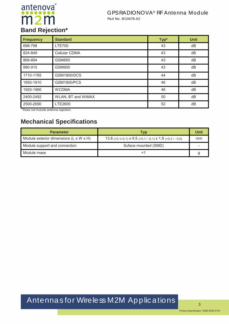
Band Rejection*Frequency Standard Typ* Unit698-798 LTE700 43 dB
824-849 Cellular CDMA 43 dB
869-894 GSM850 43 dB
880-915 GSM900 43 dB
1710-1785 GSM1800/DCS 44 dB
1850-1910 GSM1900/PCS 46 dB
1920-1980 WCDMA 46 dB
2400-2492 WLAN, BT and WiMAX 50 dB
2500-2690 LTE2600 52 dB *Does not include antenna rejection.
Mechanical SpecificationsParameter Typ Unit
Module exterior dimensions (L x W x H) 13.8 (+0.1/-0.1) x 9.5 (+0.1 / -0.1) x 1.8 (+0.2 / - 0.0) mm
Module support and connection Suface mounted (SMD) -
Module mass <1 g

Antennas for Wireless M2M Applications4
Product Specification 12MD-0050-2-PS
GPS RADIONOVA® RF Antenna ModulePart No. M10478-A2
System SpecificationsCommunication SpecificationData Output Protocol NMEA 0183
Host Interfaces UART
Default data rate on UART 4800/9600/38400/115200 bps
GPS EngineChip MTK MT3337 Chip
Channels 66 Acquisition Channels
TCXO 0.5ppm
AccuracyHorizontal Position Accuracy <2.5m CEP
Maximum Position Update Rate 5 Hz
SensitivityAcquisition (Cold) -148dBm
Acquisition (Hot) -163dBm
Tracking -165dBm
TTFFHot Start <1s
Warm Start <25s (typical)
Cold Start <35s (typical)
GeneralMaximum Altitude <18.000 km
Maximum Speed <514 m/s
Active Interference Cancellers 12 multi tone active cancellers
ISSCC2011 award
Additional Features SBAS, WAAS, EGNOS, QRZZ, GAGAN Support
EPO Orbit prediction
50% CEP, Open-Sky, 24hr Static, -130dBm, good view of the sky

Antennas for Wireless M2M Applications5
Product Specification 12MD-0050-2-PS
GPS RADIONOVA® RF Antenna ModulePart No. M10478-A2
Pin out DescriptionTable shows the designation and function of each pin on the M10478-A2 module. Please note that several pins have multiple functions.
Pin Designator DescriptionGND Ground connection
2 GND Ground connection3 GND Ground connection4 ANT_OUT RF from internal antenna to external matching circuit5 GND Ground connection6 ANT_IN RF from external matching circuit back into module7 GND Ground connection8 VCC Main DC supply, +2.8 to +4.2V9 GND Ground connection
10 HRST System reset, active lowTM 1PPS Tim Mark Out
12 VBCKUP Backup supply +2.0V to 4.2V
13 EINT2/GIO14 Hardware Baud rate select
14 EINT3/GIO1515 GND Ground connection
161718 FIXED INDICATOR Indicates once a GPS fix has been obtained. 19 GND Ground connection20 TX UART Transmit data line21 RX UART Receive data line222324
GND Ground connection
25 GND Ground connection26 HW_STANDBY Used to enable standby mode. If not used leave floating.27 GND Ground connection28 GND Ground connection
Hardware Baud rate select
GNDGND
Ground connectionGround connection
Ground connectionGround connection
GNDGND
1

Antennas for Wireless M2M Applications6
Product Specification 12MD-0050-2-PS
GPS RADIONOVA® RF Antenna ModulePart No. M10478-A2
Pin 1 Pin 28
Pin 1 Marker
Pin 18Pin 11

Antennas for Wireless M2M Applications7
Product Specification 12MD-0050-2-PS
GPS RADIONOVA® RF Antenna ModulePart No. M10478-A2
Application Schematic Example for M10478: UART - 9600 BaudThe circuit below shows a basic design for use with the UART interface and configuring the default baud rate to 9600.
Baud Rate = 9600 (Hardware configured)
Bill of MaterialDesignator Value Description/Comments QuantityC1, L1, L2 TBD Depending on device antenna matching circuit TBD
C3, C4, C5, C6 22pF capacitor Decoupling capacitor. Place close to corresponding pin 4
C2 2.2uF capacitor Decoupling capacitor. Place close to corresponding pin
L3, L4 47nH Inductor Filter component to suppress any potential host PCB noise 2
C1
L1
L2
C2 C3
C4
L3
L4
C5 C6
1

Antennas for Wireless M2M Applications8
Product Specification 12MD-0050-2-PS
GPS RADIONOVA® RF Antenna ModulePart No. M10478-A2
Host Baud Rate/Protocol SelectionThe modules default baud rate is user configurable at start-up with a hardware configuration This is limited to the values in the following table.
The baud rate and output protocol can be changed dynamically after start up using the relevant commands. Please contact Antenova for more information about protocol messages.
Hardware Baud Rate Selection Table
Baud Rate Pin13 (GIO) Pin 14 (GIO)9600 NC NC
4800
NC PD115200PD NC
38400 PD PD
NC = Not connected. Leave floatingPD = Pull down resistor to GND (10K Ω)
Host Interface OverviewUART Interface
The UART converts bytes of data to and from asynchronous start -stop bit streams as binary electrical impulses.The port contains a 16-byte FIFO, and 256 bytes of URAM. The bit rates are selectable from 4800, 9600,38400 and 115200 bps.
The default protocol is determined by hardware configuration.
The IO level from the UART port are CMOS compatible, however for RS”£” compatibility the use of external levelshifters will be required. The hardware configuration of the port baud can be changed dynamically by the use of commands. These will be active and saved as long as the VBACKP supply is applied.

Antennas for Wireless M2M Applications9
Product Specification 12MD-0050-2-PS
GPS RADIONOVA® RF Antenna ModulePart No. M10478-A2
Power SupplyThe M10478-A2 uses two DC supply inputs. VBCKUP to power the RAM and RTC sections of the reciever, and VCCto power the digital and processing sections. VBCKUP is to be applied all the time to keep these sections alive. VCC can be removed to initiate a backup power save mode (See page 9). VBCKUP can be removed if a battery isalso used at VBCKUP to maintain this supply. The supply is internally regulated for 2.8V meaning the external supplyis versatile for a range of voltage levels.
TM (1PPS)TM is a one pulse per second output from the receiver providing uses for timing purposes.
HRST (Hardware Reset Pin)The External reset pin is default high by an internal 75Kohm and should be left floating if not used. To initiate a resetThe pin needs to be pulled low. The module also initiates a reset if the VCC drops below the minimum 2.8V supply.

Antennas for Wireless M2M Applications10
Product Specification 12MD-0050-2-PS
GPS RADIONOVA® RF Antenna ModulePart No. M10478-A2
Power Management
Standby Mode
The M10478-A2 has three power saving modes.
• Standby mode• Back up mode• Periodic mode
Standby mode is a power saving mode that shuts down the RF section of the module and puts the processor intoa standby mode. The RTC is kept alive and the RAM power is maintained to keep the module configuration. The standby state can be initiated either with a hardware signal to Pin26 or by using a command.
Hardware controlled Standby:Enable standby mode by a low state to pin 26 (HW_STANDBY). To wake the module back to full power a high stateNeeds to be applied to pin 26. If Pin 26 is not to be used then it must be kept floating (not connected).
Standby mode command:Software on the host needs to send the “PMTK161 command through the UART interface.
Command M10478‐A2 standby then wakeup Current consumption (Typ)
$PMTK161,0*28 M10478‐A2 enters standby mode <200uA
Any byte M10478‐A2 wakes up from standby mode
Back up modeTo enter backup mode the VCC simply needs to be removed. Once initiated the RTC and all configuration is savedalong with any ephemeris data to allow quick TTFF once the VCC is re-applied. VBACKUP needs to be applied atall times for backup mode to run correctly.
Periodic modePeriodic mode is a module controlled mode that reduces current consumption by only waking the module for shortperiods to maintain fix data. The periodic state is user configured. Contact Antenova for more information and auser command manual.
PMTK225 setting M10478‐A2 time off/awake Current usage (Typ)
PMTK225, 2,3000,18000,72000
Module sleeps for 12secs, then wakes for 3secs periodiclly. 72000 is for a cold boot condition .
<200uA

Antennas for Wireless M2M Applications11
Product Specification 12MD-0050-2-PS
GPS RADIONOVA® RF Antenna ModulePart No. M10478-A2
EPO (Extended Prediction Orbit) data serviceThe EPO allows the use of up to a 30-day orbit predictions that can be used to aid the module for an instant fix solution
• A proxy server on the customers side to update EPO files from the MTK server daily.• Application software to access the proxy server through the internet (optional if host device can access internet• Software on host device to send EPO data to M10478-A2 module to allow instant fix by using EE data.
Please contact Antenova for more information. Requires permission from MTK to use service.
AIC (Active Interference Cancellation)The AIC feature provides effective narrow-band interference and jamming elimination. The GPS signal can be recovered from the jammed signal and allows users to obtain better navigation quality. This can be beneficial sinceMany of today’s devices have more and more functionality with regards to transmitters with many on-board antenna's

Antennas for Wireless M2M Applications12
Product Specification 12MD-0050-2-PS
GPS RADIONOVA® RF Antenna ModulePart No. M10478-A2
External MatchingThe M10478-A2 module uses a matching circuit on the host PCB in order to fine-tune the on-board antenna to each specific application. This “external matching” allows compensating for the detuning of the antenna caused by various different components that can be close to the M10478-A2 module in the actual application (plastic case, battery, speakers etc).
The external matching must be placed on the host PCB between ANT_OUT (PIN3) and ANT_IN (PIN1). Although 2 components are typically more than enough to match the antenna to the 50Ω impedance required, a Π-network topology with 3 components is recommended for safe proving.
Schematic
Both low-pass and hi-pass topologies for the matching network can be used with similar results. As the same footprint can be used for both topologies, the exact type and value of the components used can be determined during the optimization phase.
• The initial values can be simply chosen as the null-circuit (no impedance matching):
• Hi-pass:
• C1 = 18pF
• L1, L2 = Not Fitted
• Low-pass:
• L1 = Jumper (0Ω resistor)
• C1, C2 = Not Fitted

Antennas for Wireless M2M Applications13
Product Specification 12MD-0050-2-PS
GPS RADIONOVA® RF Antenna ModulePart No. M10478-A2
Type of Matching Components• Capacitors:
• Use 0402, COG components
• Inductors:
• High-Q, wire wound inductors in 0402 size are recommended for maximum performance, e.g. Murata LQW15 series
• Good quality multi-layer type inductors (e.g. Murata LQG15 series) can also be used as a lower cost alternative
Matching ProcedureThe types and values of the matching components must be chosen so that the impedance seen by port ANT_IN (PIN4) is as close as possible as 50Ω. Although it is a relatively simple operation, it requires some RF skills and a VNA (Vector Network Analyzer). Please contact an Antenova M2M FAE to get support on defining the optimal matching for your specific device.
External Antenna SupportA low cost external circuit can be used to provide external antenna support. Please contact Antenova for more information, and example circuit.
PCB Matching Circuit LayoutThe layout of the external matching circuit should be done using the following guidelines:
• Minimize the length of the tracks connecting the ANT_OUT and ANT_IN pads to the matching
• Minimize the length of the tracks between the components
• Use a solid groundplane under the matching circuit area
• Absolutely avoid routing any track under the matching circuit area
• Connect the top ground layer with the ground layer underneath using several vias
Layout drawings (Gerber or other format) are available from Antenova. Please contact your local FAE.
Example of external matching circuit layout
Matching Circuit

Antennas for Wireless M2M Applications14
Product Specification 12MD-0050-2-PS
GPS RADIONOVA® RF Antenna ModulePart No. M10478-A2
Internal Antenna ClearanceThe M10478-A2 module internal antenna requires a small clearance on the host PCB to operate. The clearance means that no Ground or tracks of any kind are allowed to be within this area. This must also be clear through the entire PCB stack up. The minimum area needed clear is 6mm X 4.87mm.
Keep out area
Top view of M10478 Footprint
End view - 4 layer PCB stack-up

Antennas for Wireless M2M Applications15
Product Specification 12MD-0050-2-PS
GPS RADIONOVA® RF Antenna ModulePart No. M10478-A2
Typical RF Antenna Module PlacementNote: Module placement locations and orientations are critical for achieving optimal system performance. It is strongly recommended to contact Antenova M2M for design recommendations.
Front View
Back View
Side View
Sky
Below is the placement shown on the Antenova evaluation PCB.

Antennas for Wireless M2M Applications16
Product Specification 12MD-0050-2-PS
GPS RADIONOVA® RF Antenna ModulePart No. M10478-A2
Typical Antenna Matching ResultsTypical antenna matching as seen by ANT_IN (Pin 3) is shown in the following plot. The matching bandwidth at -10dB is typically 30MHz. Measured on M10478-U1 test board.
Typical antenna return loss after matching
1250 1350 1450 1550 1650 1750 1850-35
-30
-25
-20
-15
-10
-5
0
5
[MHz]
[dB] Atyune
1
2
MARKERS: MHz dBM10478-A2_0p7Fshu_4n7Hser.S1P - S11
1: 1573.422: 1577.42
-29.49-26.21
0 10 25 50 100 200
-100j
-50j
-25j
-10j
10j
25j
50j
100j
∞12
MARKERS: MHz ΩM10478-A2_0p7Fshu_4n7Hser.S1P - S11
1: 1573.422: 1577.42
51.89- 2.85j 54.49+ 2.44j
Atyune

Antennas for Wireless M2M Applications17
Product Specification 12MD-0050-2-PS
GPS RADIONOVA® RF Antenna ModulePart No. M10478-A2
Front-end RejectionThe figure below shows the rejection for the input SAW filter before the RF input, including the effect of pads, tracks and decoupling. The plot can be useful to calculate the isolation required from adjacent transmitters in order to avoid the saturation of the LNA.
Input SAW Rejection - Wideband
Input SAW Rejection - Narrowband
1200 1300 1400 1500 1600 1700 1800 1900 2000-80
-70
-60
-50
-40
-30
-20
-10
0
10
[MHz]
[dB] Atyune
12
MARKERS: MHz dBM10478-A2 FrontEndRejection_1.S2P - S21
1: 1573.422: 1577.42
-1.52 -1.46
700 1230 1760 2290 2820 3350 3880 4410 4940 5470 6000-80
-70
-60
-50
-40
-30
-20
-10
0
10
[MHz]
[dB] Atyune
12

Antennas for Wireless M2M Applications18
Product Specification 12MD-0050-2-PS
GPS RADIONOVA® RF Antenna ModulePart No. M10478-A2
Module Placement GuidelinesDue to the internal antenna, care must be taken when defining the placement of the module on the host PCB. Here are some guidelines that should be used when deciding the position of the module.
• The module top edge must be placed almost level with the edge of the host PCB
• The edge of the host PCB that the module is to be placed at must be a minimum of 40mm in length.
• The central placement of the module is advised. However, an offset placement is also possible.
• For an offset closer to the PCB edge to the right side of the module, a minimum of 10mm distance is required to the edge of the host PCB.
• For an offset closer to the PCB edge on the left side of the module, a minimum of 15mm distance is required to the edge of the host PCB. This additional distance is due to the matching circuit placement.
Module top edge placed level with the edge of the host PCB
≥40mm
≥10mm
Right Side Edge Offset

Antennas for Wireless M2M Applications19
Product Specification 12MD-0050-2-PS
GPS RADIONOVA® RF Antenna ModulePart No. M10478-A2
• For an offset closer to the PCB edge to the left side of the module, a minimum of 15mm distance is required to the edge of the host PCB. This additional distance is due to the matching circuit placement.
• The antenna uses the host PCB ground to effectively radiate. As such, a GND plane must be placed on the host PCB on at least one layer.
• In the example below, the only area void of GND is the antenna keep-out area.
≥15mm
Left Side Edge OffsetSpace needed for external matching circuit
Antenna keep-out area

Antennas for Wireless M2M Applications20
Product Specification 12MD-0050-2-PS
GPS RADIONOVA® RF Antenna ModulePart No. M10478-A2
• An ideal stack-up for a host PCB would be to use the top and bottom layers as GND planes, while using the internal layers for any signal and power planes. This not only helps the GPS antenna to perform effectively, but also helps to reduce any potential noise issues that can be associated with mixed signal PCB’s.
• An exaggerated example below shows a 4 layer host PCB, GND flooding all available space not used by signals or components.
Please contact Antenova M2M for advice on placement.
Antennas for Wireless M2M Applications21
Product Specification 12MD-0050-2-PS
GPS RADIONOVA® RF Antenna ModulePart No. M10478-A2
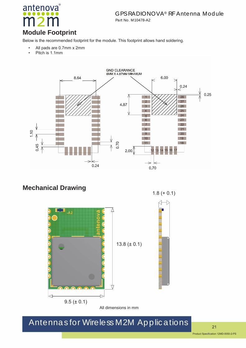
Module FootprintBelow is the recommended footprint for the module. This footprint allows hand soldering.
• All pads are 0.7mm x 2mm• Pitch is 1.1mm
Mechanical Drawing1.8 (+ 0.1)
All dimensions in mm9.5 (± 0.1)
13.8 (± 0.1)

Antennas for Wireless M2M Applications22
Product Specification 12MD-0050-2-PS
GPS RADIONOVA® RF Antenna ModulePart No. M10478-A2
Reflow SolderingPlacementTypical placement systems used for any BGA/LGA package are acceptable. Recommended nozzle diameter for placement: 5mm
Soldering PasteUse of “No Clean” soldering paste is strongly recommended, as it does not require cleaning after the soldering process has taken place. An example of suitable soldering paste is Alpha OM350.
SolderingThe recommended soldering profile for M10478-A2 is shown below. However, it is the responsibility of the Contract Manufacturer to determine the exact reflow profile used, taking into consideration the parameters of the host PCB, solder paste used, etc.
Profile Feature Pb-Free Solder
Pre-Heat
Temperature (Ts ) Min 130°C
Temperature (Ts ) Max 220°C
Time (ts ) <150s
ReflowLiquidus Temperature - (Tl ) 220°C
Time (tl ) 45-90s
Peak Package Body Temperature (Tp) 245°C
Time within 5°C of peak temp (tp)30s
Average Ramp up rate - Ts (max) to (Tp)3°C/s
Ramp Down Rate 6°C/s max
Example Reflow profile
The Pb Free Process-Package Peak Reflow Temperature is 260ºC.
Exceeding the maximum soldering temperature could permanently damage the module.

Antennas for Wireless M2M Applications23
Product Specification 12MD-0050-2-PS
GPS RADIONOVA® RF Antenna ModulePart No. M10478
Multiple SolderingThe M10478-A2 module can be submitted up to 2 reflow soldering processes.
Upside-down soldering is acceptable but it is recommended that the Contract Manufacturer qualify the process before mass production. The second reflow must take place within the recommended floor life limit (MSL3). Please contact Antenova for further information.
Hand Soldering Hand-soldering and rework of the M10478-A2 module is acceptable, however care must be taken to avoid short circuits due to the small size of the module pads.

Antennas for Wireless M2M Applications24
Product Specification 12MD-0050-2-PS
GPS RADIONOVA® RF Antenna ModulePart No. M10478-A2
Quality and Environmental SpecificationsTest Standard Parameters
PCB Inspection IPC-6012B, Class 2. Qualification and Performance Specification for Rigid Printed Boards - Jan 2007
Assembly Inspection
IPC-A-610-D, Class 2 “Acceptability of electronic assemblies”
Temperature Range
ETSI EN 300 019-2-7 specification T 7.3 -30 °C, +25 °C, +85 °C, operating
Damp Heat ETSI EN 300 019-2-7 specification T 7.3 +70 °C, 80% RH, 96 hrs, non-operating
Thermal Shock ETSI EN 300 019-2-7 specification T 7.3 E -40 °C ... +85 °C, 200 cycles
Vibration ISO16750-3 Random vibration, 10~1000Hz, 27.8m/s2, 8hrs/axis, X, Y, Z 8hrs for each 3 axis non-operating
Shock ISO16750-3 Half-sinusoidal 50g, 6ms, 10time/face, ±X, ±Y and ±Z non-operating
Free Fall ISO16750-3 1m height, 2 drops on opposite side
ESD Sensitivity JEDEC, JESD22-A114 ESD Sensitivity Testing Human Body Model (HBM). Class 2
JEDEC, JESD22-A115 ESD Sensitivity Testing Machine Model (MM), Class B
+2000V - Human hand assembly
+200V - Machine automatic final assembly
Shear IEC 60068-2-21, Test Ue3: Shear Force of 5N applied to the side of the PCB
Moisture/Reflow Sensitivity
IPC/JEDEC J-STD-020D.1 MSL3
Storage (Dry Pack)
IPC/JEDEC J-STD-033C MSL3
Solderability EN/IEC 60068-2-58 Test Td More than 90% of the electrode should be covered by solder. Solder temperature 245 °C ± 5 °C
Moisture Sensitivity
Antenova ships all devices dry packed in tape on reel with desiccant and moisture level indicator sealed in an airtight package. If on receiving the goods the moisture indicator is pink in color or a puncture of the airtight seal packaging is observed, then follow J-STD-033 “Handling and Use of Moisture/Reflow Sensitive Surface Mount Devices”.
Storage (Out of Bag)The M10478-A2 modules meet MSL Level 3 of the JEDEC specification J-STD-020D - 168 hours Floor Life (out of bag) ≤30 °C/60% RH. If the stated floor life expires prior to reflow process then follow J-STD-033 “Handling and Use of Moisture/Reflow Sensitive Surface Mount Devices”.

Antennas for Wireless M2M Applications25
Product Specification 12MD-0050-2-PS
GPS RADIONOVA® RF Antenna ModulePart No. M10478-A2
Hazardous material regulation conformanceThe RF antenna module meets RoHS requirements.
Packaging Tape Characteristics
WFEP0P1P232.00±0.3 14.20±0.1 1.75±0.2 4.00±0.1 16±0.1 2.00±0.1
D0 B0 T K0 A0 D11.55±0.1 14.80±0.1 0.30±0.1 2.00±0.1 10.50±0.05 0.85±0.1
Dimensions in mm
Quantity Leading Space Trailing Space1000 pcs / reel 50 blank module holders 50 blank module holders
Antennas for Wireless M2M Applications26
Product Specification 12MD-0050-2-PS
GPS RADIONOVA® RF Antenna ModulePart No. M10478-A2
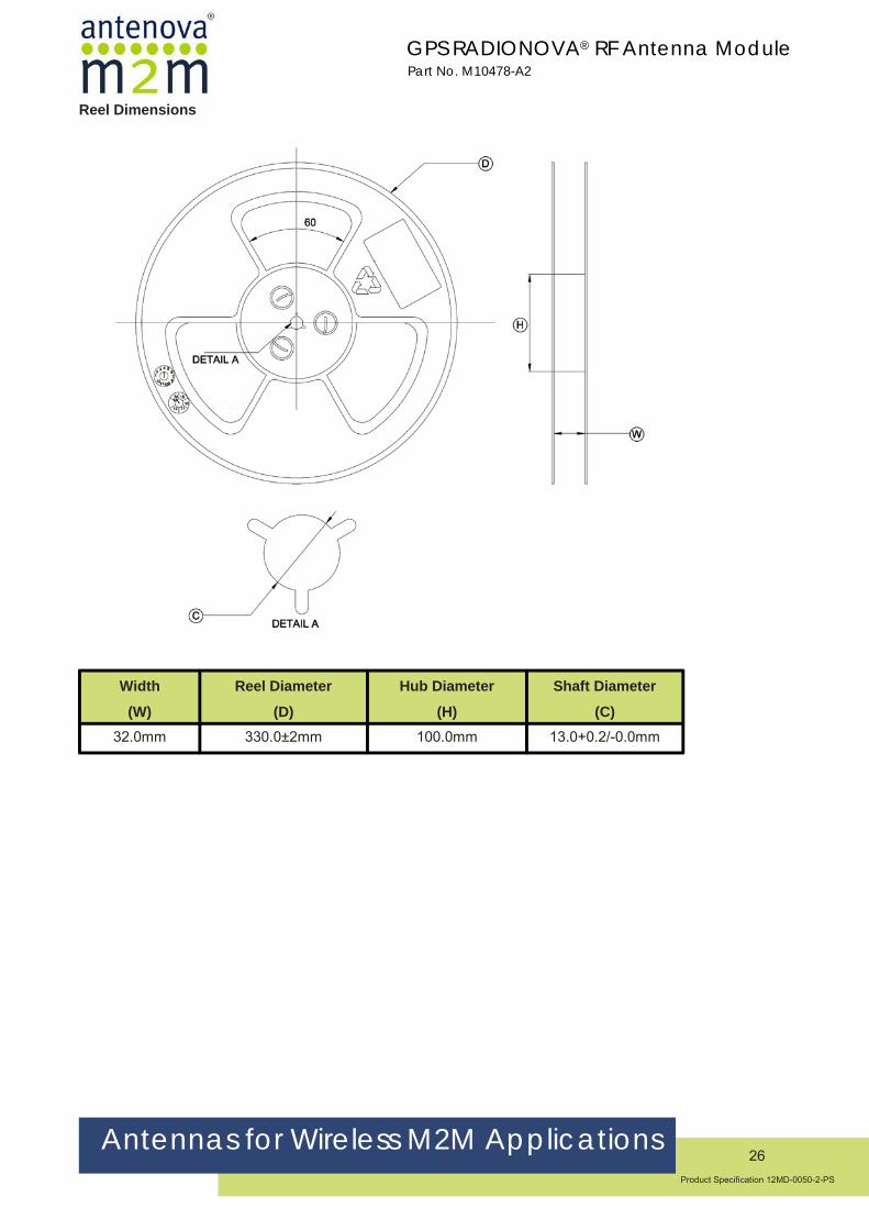
Reel Dimensions
Width
(W)
Reel Diameter
(D)
Hub Diameter
(H)
Shaft Diameter
(C)32.0mm 330.0±2mm 100.0mm 13.0+0.2/-0.0mm

Antennas for Wireless M2M Applictions27
Product Specification 12MD-0050-2-PS
Corporate HeadquartersAntenova Ltd.Far Field HouseAlbert RoadStow-cum-QuyCambridge, CB25 9ARUK
Tel: +44 (0) 1223 810600Fax: +44 (0) 1223 810650Email: [email protected]
USA HeadquartersAntenova USARogers Business Park2541 Technology Drive, Suite 403Elgin, IL 60124USA
Tel: +1 (847) 551-9710Fax: +1 (847) 551-9719Email: [email protected]
Asia HeadquartersAntenova Asia Ltd.4F, No. 324, Sec. 1, Nei-Hu RoadNei-Hu DistrictTaipei 11493Taiwan, ROC
Tel: +886 (0) 2 8797 8630Fax: +886 (0) 2 8797 6890Email: [email protected]
Copyright® 2013 Antenova Ltd. All Rights Reserved. Antenova®, Antenova M2M, RADIONOVA® and the Antenova and Antenova M2M logos are trademarks and/or registered trademarks of Antenova Ltd. Any other names and/or trademarks belong to their respective
companies.
The materials provided herein are believed to be reliable and correct at the time of print. Antenova does not warrant the accuracy or completeness of the information, text, graphics or other items contained within these information. Antenova further assumes no responsibility for
the use of this information, and all such information shall be entirely at the user’s risk.
Release Date 05 February 2013