part number: 00016-52030 code: cl7 - sparks toyota
TRANSCRIPT

Document # 16.01.00 PIO/DIO Rev. A 06/23/08TOYOTA YARIS 2008- ELECTRONIC CRUISE CONTROL KIT
Part Number: 00016-52030 Code: CL7 Section I – Installation Preparation Kit Contents
Item # Qty. Description 1. 57A-02337 1 Cruise Control Module 2. 57A-02338 1 Switch Interface Module 3. 57A-02341 1 Main Wiring Harness/Automatic 4. 57A-02339 1 Pedal Interface Harness 5. 55A-01648 2 Hardware Kit 6. 57A-02342 1 Control Switch
Contents of Hardware Bag, 55A-01648
Qty Description 6 T-taps, 18-22 AWG Female
10 Wire Zip Ties 2 Adhesive backed Foam Sq. 1 8-pin Control Switch connector 2 Weather sealant
1 Cruise Control Switch form 1 Connector, 14- 18 AWG
1 Posi-Tap TM Connector
Additional Items Required For Installation
Conflicts Note:
General Applicability Automatic Transmission
Recommended Tools Safety Tools
Gloves, Safety Glasses Special Tools
Torque Wrench (36. in. lbs.) Temp. Probe Installation Tools
Pliers For t-taps Crimping Tool For NSS (A/T only) Side cutter To cut wire ties Drill Bit or Knockout Punch 9.5mm or 3/8” (for switch) Special Chemicals Alcohol/Water Solution
Recommended Sequence of Application Item # Accessory 1 2 3
*Mandatory
Legend
6
1
2
3 4
5
SPECIAL NOTE: Installation Sequences After TMS and Safety mandated preparatory steps have been taken, the installation sequence is the suggested method for completing the accessory installation. In some instances the suggested sequence is written for one associate to install and in others the sequence is given as part of a team accessory installation. Unless otherwise stated in the document, the associates may perform the installation steps in any order to make the installation as efficient as possible while maintaining consistent quality.
Southeast Toyota Distributors, LLC Page 1 of 8
TOYOTA YARIS ELECTRONIC CRUISE KIT
Figure 1
Switch Interface Module
Figure 2
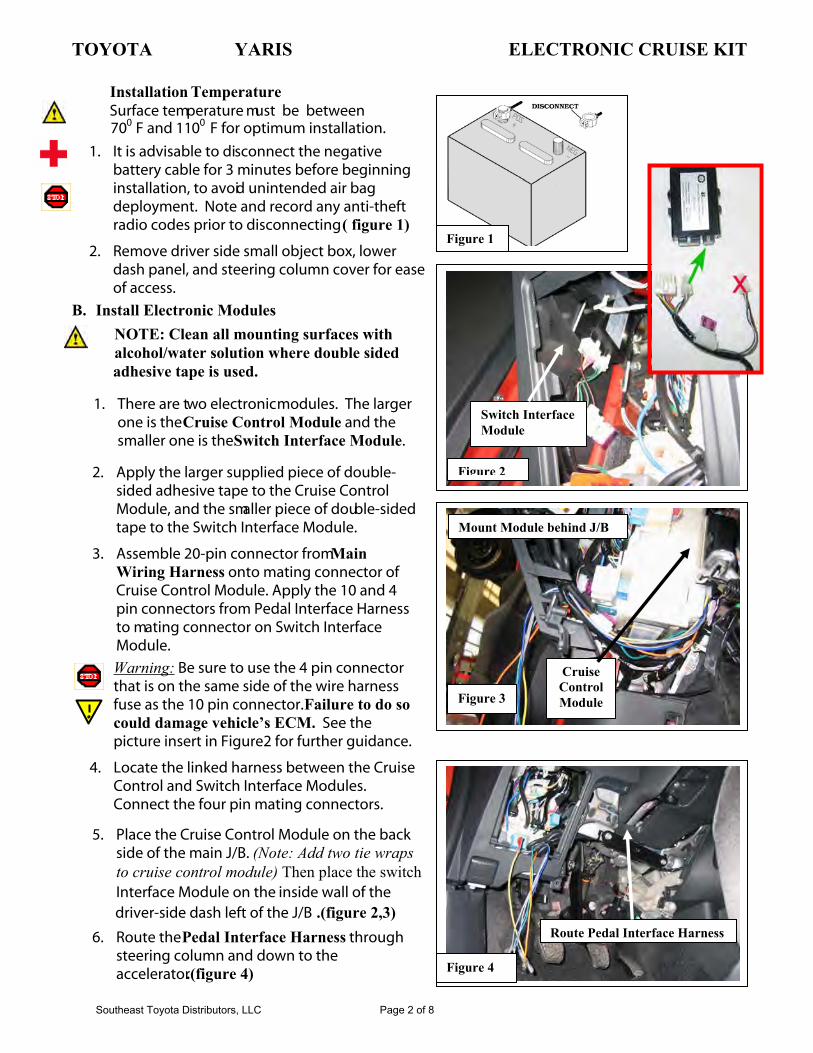
1. It is advisable to disconnect the negative battery cable for 3 minutes before beginning installation, to avoid unintended air bag deployment. Note and record any anti-theft radio codes prior to disconnecting ( figure 1)
2. Remove driver side small object box, lower dash panel, and steering column cover for ease of access.
B. Install Electronic Modules
1. There are two electronicmodules. The larger one is the Cruise Control Module and the smaller one is the Switch Interface Module.
2. Apply the larger supplied piece of double- sided adhesive tape to the Cruise Control Module, and the smaller piece of double-sidedtape to the Switch Interface Module.
3. Assemble 20-pin connector from MainWiring Harness onto mating connector of Cruise Control Module. Apply the 10 and 4 pin connectors from Pedal Interface Harness to mating connector on Switch Interface Module.
Warning: Be sure to use the 4 pin connector that is on the same side of the wire harness fuse as the 10 pin connector.Failure to do so could damage vehicle’s ECM. See the picture insert in Figure 2 for further guidance.
Figure 3
CruiseControl Module
Mount Module behind J/B
4. Locate the linked harness between the Cruise Control and Switch Interface Modules. Connect the four pin mating connectors.
Route Pedal Interface Harness
Figure 4
5. Place the Cruise Control Module on the back side of the main J/B. (Note: Add two tie wraps to cruise control module) Then place the switchInterface Module on the inside wall of the driver-side dash left of the J/B .(figure 2,3)
6. Route the Pedal Interface Harness through steering column and down to the accelerator.(figure 4)
Installation TemperatureSurface temperature m ust be between 700 F and 1100 F for optimum installation.
NOTE: Clean all mounting surfaces withalcohol/water solution where double sided adhesive tape is used.
Southeast Toyota Distributors, LLC Page 2 of 8

TOYOTA YARIS ELECTRONIC CRUISE KIT Section II – Installation Procedure
Figure 5
Accelerator 6-pin Connector7. Locate the 6 pin plug and mate connectorson the Pedal Interface Harness. Remove the accelerator 6-pin connector and apply to mating connector of Pedal Interface Harness. Apply the other connector to the accelerator. (figure 5)
C. Wiring Connections (figures 6-16)1. Use the supplied self-stripping connectors
from hardware pack to apply a T-Taponto the following J/B wires:
2. Use the following wires from the Main Harness to connect to vehicle tapped wire:
Function Connector PinSeeFig.
VehicleColor
IGN 4B 9 7 RED
BRAKE + A13 1 8, 9 BLACK
BRAKE - A13 2 8, 9 GREEN
VSS 4B 26 7 PURPLE
NSS C27 9 15, 16 Lt. BLUE
Figure 6
Wire Connections
FunctionCruise Harness
ColorVehicle T-
Tap Wire
IGN ORANGE RED
BRAKE + BROWN BLACK
BRAKE - BROWN/WHITE GREEN
VSS BLUE PURPLE
NSS RED Lt. BLUE
3. Remove driver-side kick panel and 10mm bolt to apply green wire from the Cruise Control Module to ground point D1 in figure 10.
4. Locate the main harness firewall grommet.
5. Undernealth the dash to the left of the steering column cut a small slit in the indented side of the grommet as shown in fig. 11. & route the red wire (NSS) through the slit into the engine com- partment & apply sealant. Route cable as shown in fig. 12, 13 & 15.
CONNECTOR 4B
OF JUNCTION BOX
Figure 7
Blue (Cruise)Purple (Vehicle)
Orange(Cruise)Red(Vehicle)
Back (Wire side) of Connector 4B
Southeast Toyota Distributors, LLC Page 3 of 8

TOYOTA YARIS ELECTRONIC CRUISE KIT Section II – Installation Procedure
6. Find connector C27 above transmission. Use the supplied Posi-Tap TM to connect the red wire from the relay on the Main Wiring Harness tolight blue wire pin 9. (figure 15, 16 & 17)
7. Apply the supplied weather sealant to the connection. Be sure all of connection is sealed properly.
Figure 10
GROUND POINT D1
8. Secure Cruise Control and Switch InterfaceModule harnesses with zip ties away frommoving parts. Secure Relay on harness as shown in figure 14.
Figure 8
BRAKE
Figure 9
Function Connector Pin Vehicle wire Color
BRAKE - A13 2 GREEN
BRAKE + A13 1 BLACK
Function Cruise HarnessColor
Vehicle T-TapWire
BRAKE + BROWN BLACK
BRAKE - BROWN/WHITE GREEN
Brown/White(Cruise)Green (Vehicle)Brown (Cruise)
Black (Vehicle)
Note: Apply 1 tie wrap @connector shown in fig 15
Fig. 11
Fig. 12
Red wire (NSS) inserted through the main harnessgrommet under dash to access the engine compartment
Red wire exiting the grommet & routing toward the transmission connector.
Southeast Toyota Distributors, LLC Page 4 of 8

TOYOTA YARIS ELECTRONIC CRUISE KIT Section II – Installation Procedure
Figure 16
Red (Cruise)Lt. Blue (Vehicle)
Figure 14 n
Lt. Blue Wire Pin 9
Fig. 13
Red wire routing under battery tray with tie wrap locations.Optional step: Remove battery for ease of tie wrap installation.
Fig. 15
Tie wrap location at the transmission connectorNote: Add weather sealant to the connector.
Southeast Toyota Distributors
Relay Mounting Locatio
Figure 17
, LLC Page 5 of 8

TOYOTA YARIS ELECTRONIC CRUISE KIT Section II – Installation Procedure
D. Install Control Switch (Figure 17,18) DRILL 9.5MM HOLE AT 17 DEGREE ANGLE, 30 mm from edge of plastic towards Steering Wheel, 65 mm from top of plastic down from Steering Wheel.
1. Use the level wedges on the Control Switch as an angle template to drill a 9.5mm hole in the lower shroud of the steering column cover. Position lock-washers as shown.
2. Apply nut and position Control Switch for driver’s best view.
3. Assemble 8-pin connector from the sack parts to the mating wire colors on the Control switch harness.
4. Route the assembled Control Switch harness down to the mating connector of the Cruise Control harness.
Figure 17
5. Secure the Control Switch harness with zip ties away from moving parts.
E. Testing
1. Reconnect negative battery cable and torque to 36 in. lbs. Reenter anti-theft radio codes.
2. Turn ignition on. Apply the on/off button of Cruise Control Switch.
F. Reassembly 1. Reinstall all removed pieces taking care to
ensure harnesses and wiring connections are properly secured.
2. Make sure all harnesses are not pinched or bound by trim pieces.
Figure 18
Southeast Toyota Distributors, LLC Page 6 of 8

TOYOTA YARIS ELECTRONIC CRUISE KIT Section III – Wiring Diagram
Southeast Toyota Distributors, LLC Page 7 of 8
FUNCTION CHECKTHE CRUISE CONTROL ALLOWS YOU TO CRUISE THE VEHICLE AT ADESIRED SPEED OVER 40 KM/H (25 MPH) EVEN WITH YOUR FOOTOFF THE ACCELERATOR PEDAL. YOUR CRUISING SPEED CAN BE MAIN-TAINED UP OR DOWN GRADES WITHIN THE LIMITS OF ENGINEPERFORMANCE, ALTHOUGH A SLIGHT SPEED CHANGE MAY OCCURWHEN DRIVING UP OR DOWN THE GRADES. ON STEEPER HILLS, AGREATER SPEED CHANGE WILL OCCUR SO IT IS BETTER TO DRIVEWITHOUT THE CRUISE CONTROL.
CAUTIONTO HELP MAINTAIN MAXIMUM CONTROL OF YOUR VEHICLE, DO NOT USE THECRUISE CONTROL WHEN DRIVING IN HEAVY OR VARYING TRAFFIC, OR ON SLIP-
PERY (RAINY, ICY OR SNOW–COVERED) OR WINDING ROADS.
AVOID VEHICLE SPEED INCREASES WHEN DRIVING DOWNHILL. IF THE VEHICLESPEED IS TOO FAST IN RELATION TO THE CRUISE CONTROL SET SPEED, CANCEL
THE CRUISE CONTROL THEN DOWNSHIFT THE TRANSMISSION TO USE ENGINEBRAKING TO SLOW DOWN.
CRUISE CONTROL OPERATION
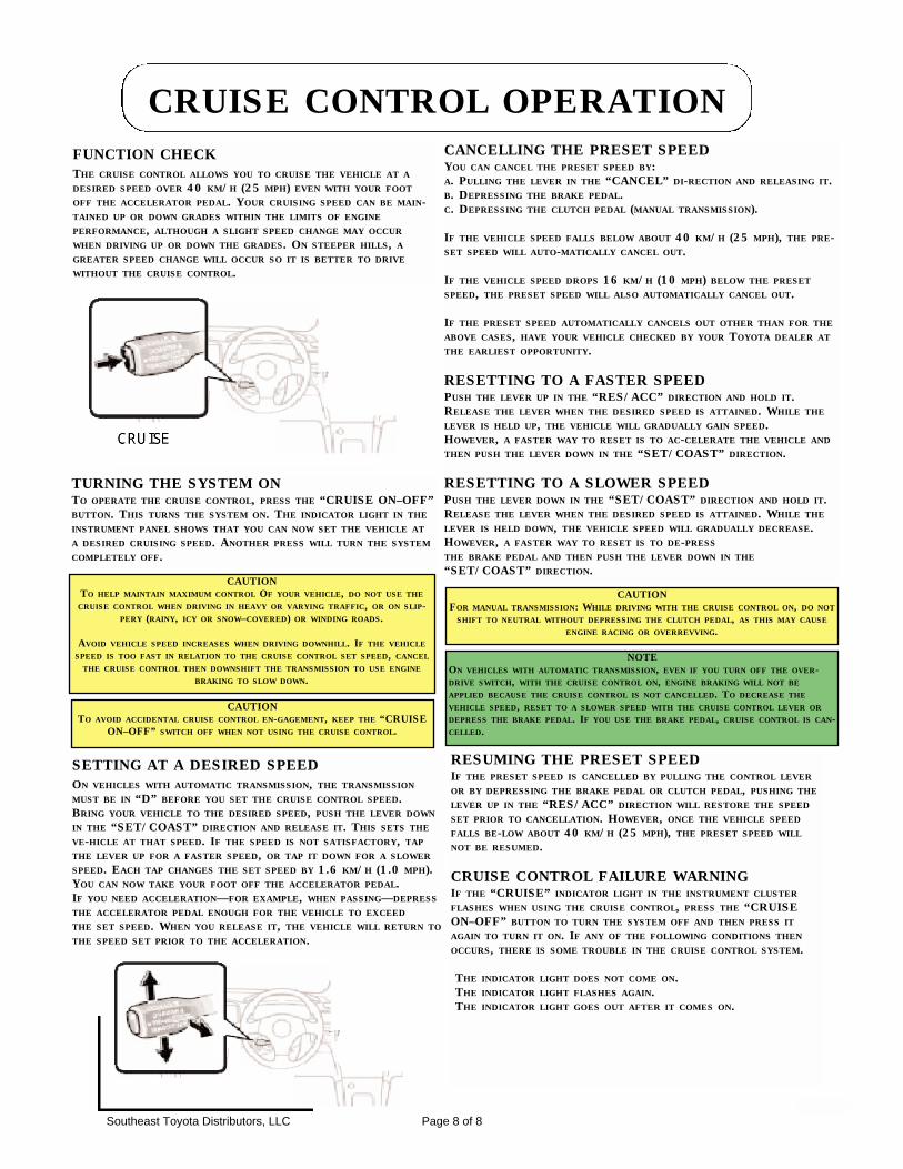
TURNING THE SYSTEM ONTO OPERATE THE CRUISE CONTROL, PRESS THE “CRUISE ON–OFF”BUTTON. THIS TURNS THE SYSTEM ON. THE INDICATOR LIGHT IN THEINSTRUMENT PANEL SHOWS THAT YOU CAN NOW SET THE VEHICLE ATA DESIRED CRUISING SPEED. ANOTHER PRESS WILL TURN THE SYSTEMCOMPLETELY OFF.
CAUTIONTO AVOID ACCIDENTAL CRUISE CONTROL EN-GAGEMENT, KEEP THE “CRUISE
ON–OFF” SWITCH OFF WHEN NOT USING THE CRUISE CONTROL.
CANCELLING THE PRESET SPEEDYOU CAN CANCEL THE PRESET SPEED BY:A. PULLING THE LEVER IN THE “CANCEL” DI-RECTION AND RELEASING IT.B. DEPRESSING THE BRAKE PEDAL.C. DEPRESSING THE CLUTCH PEDAL (MANUAL TRANSMISSION).
IF THE VEHICLE SPEED FALLS BELOW ABOUT 40 KM/H (25 MPH), THE PRE-SET SPEED WILL AUTO-MATICALLY CANCEL OUT.
IF THE VEHICLE SPEED DROPS 16 KM/H (10 MPH) BELOW THE PRESETSPEED, THE PRESET SPEED WILL ALSO AUTOMATICALLY CANCEL OUT.
IF THE PRESET SPEED AUTOMATICALLY CANCELS OUT OTHER THAN FOR THEABOVE CASES, HAVE YOUR VEHICLE CHECKED BY YOUR TOYOTA DEALER ATTHE EARLIEST OPPORTUNITY.
RESETTING TO A FASTER SPEEDPUSH THE LEVER UP IN THE “RES/ACC” DIRECTION AND HOLD IT.RELEASE THE LEVER WHEN THE DESIRED SPEED IS ATTAINED. WHILE THELEVER IS HELD UP, THE VEHICLE WILL GRADUALLY GAIN SPEED.HOWEVER, A FASTER WAY TO RESET IS TO AC-CELERATE THE VEHICLE ANDTHEN PUSH THE LEVER DOWN IN THE “SET/COAST” DIRECTION.
RESETTING TO A SLOWER SPEEDPUSH THE LEVER DOWN IN THE “SET/COAST” DIRECTION AND HOLD IT.RELEASE THE LEVER WHEN THE DESIRED SPEED IS ATTAINED. WHILE THELEVER IS HELD DOWN, THE VEHICLE SPEED WILL GRADUALLY DECREASE.HOWEVER, A FASTER WAY TO RESET IS TO DE-PRESSTHE BRAKE PEDAL AND THEN PUSH THE LEVER DOWN IN THE“SET/COAST” DIRECTION.
SETTING AT A DESIRED SPEEDON VEHICLES WITH AUTOMATIC TRANSMISSION, THE TRANSMISSIONMUST BE IN “D” BEFORE YOU SET THE CRUISE CONTROL SPEED.BRING YOUR VEHICLE TO THE DESIRED SPEED, PUSH THE LEVER DOWNIN THE “SET/COAST” DIRECTION AND RELEASE IT. THIS SETS THEVE-HICLE AT THAT SPEED. IF THE SPEED IS NOT SATISFACTORY, TAPTHE LEVER UP FOR A FASTER SPEED, OR TAP IT DOWN FOR A SLOWERSPEED. EACH TAP CHANGES THE SET SPEED BY 1.6 KM/H (1.0 MPH).YOU CAN NOW TAKE YOUR FOOT OFF THE ACCELERATOR PEDAL.IF YOU NEED ACCELERATION—FOR EXAMPLE, WHEN PASSING—DEPRESSTHE ACCELERATOR PEDAL ENOUGH FOR THE VEHICLE TO EXCEEDTHE SET SPEED. WHEN YOU RELEASE IT, THE VEHICLE WILL RETURN TOTHE SPEED SET PRIOR TO THE ACCELERATION.
CAUTIONFOR MANUAL TRANSMISSION: WHILE DRIVING WITH THE CRUISE CONTROL ON, DO NOT
SHIFT TO NEUTRAL WITHOUT DEPRESSING THE CLUTCH PEDAL, AS THIS MAY CAUSEENGINE RACING OR OVERREVVING.
RESUMING THE PRESET SPEEDIF THE PRESET SPEED IS CANCELLED BY PULLING THE CONTROL LEVEROR BY DEPRESSING THE BRAKE PEDAL OR CLUTCH PEDAL, PUSHING THELEVER UP IN THE “RES/ACC” DIRECTION WILL RESTORE THE SPEEDSET PRIOR TO CANCELLATION. HOWEVER, ONCE THE VEHICLE SPEEDFALLS BE-LOW ABOUT 40 KM/H (25 MPH), THE PRESET SPEED WILLNOT BE RESUMED.
CRUISE CONTROL FAILURE WARNINGIF THE “CRUISE” INDICATOR LIGHT IN THE INSTRUMENT CLUSTERFLASHES WHEN USING THE CRUISE CONTROL, PRESS THE “CRUISEON–OFF” BUTTON TO TURN THE SYSTEM OFF AND THEN PRESS ITAGAIN TO TURN IT ON. IF ANY OF THE FOLLOWING CONDITIONS THENOCCURS, THERE IS SOME TROUBLE IN THE CRUISE CONTROL SYSTEM.
THE INDICATOR LIGHT DOES NOT COME ON.THE INDICATOR LIGHT FLASHES AGAIN.THE INDICATOR LIGHT GOES OUT AFTER IT COMES ON.
NOTEON VEHICLES WITH AUTOMATIC TRANSMISSION, EVEN IF YOU TURN OFF THE OVER-DRIVE SWITCH, WITH THE CRUISE CONTROL ON, ENGINE BRAKING WILL NOT BEAPPLIED BECAUSE THE CRUISE CONTROL IS NOT CANCELLED. TO DECREASE THEVEHICLE SPEED, RESET TO A SLOWER SPEED WITH THE CRUISE CONTROL LEVER ORDEPRESS THE BRAKE PEDAL. IF YOU USE THE BRAKE PEDAL, CRUISE CONTROL IS CAN-CELLED.
Southeast Toyota Distributors, LLC Page 8 of 8