pci bridge design manual - 3rd edition, first release, november 2011 · · 2017-05-01color logos...
TRANSCRIPT

Color logos
Black only logos
Reverse logos
BRIDGE DESIGN MANUAL3rd Edition, First Release, November 2011
MNL-133-111st Edition, First Printing, 19972nd Edition, First Printing, 2003
PCI BRIDGE DESIGN MANUAL_______________________________________________________________________________CHAPTER 6 PRELIMINARY DESIGN
Table of Contents
6 - 1 (Nov 11)
NOTATION ............................................................................................................................................................................................................. 6 - 3 6.0 SCOPE ............................................................................................................................................................................................................... 6 - 5 6.1 PRELIMINARY PLAN ................................................................................................................................................................................. 6 - 5
6.1.1 General ................................................................................................................................................................................................... 6 - 5 6.1.2 Development ........................................................................................................................................................................................ 6 - 5 6.1.3 Factors for Consideration .............................................................................................................................................................. 6 - 5
6.1.3.1 General .......................................................................................................................................................................................... 6 - 5 6.1.3.2 Site ................................................................................................................................................................................................... 6 - 5 6.1.3.3 Structure ....................................................................................................................................................................................... 6 - 5 6.1.3.4 Hydraulics .................................................................................................................................................................................... 6 - 6 6.1.3.5 Construction ............................................................................................................................................................................... 6 - 6 6.1.3.6 Utilities .......................................................................................................................................................................................... 6 - 6
6.1.4 Required Details ................................................................................................................................................................................. 6 - 7 6.2 SUPERSTRUCTURE ................................................................................................................................................................................. 6 - 10
6.2.1 Beam Layout ..................................................................................................................................................................................... 6 - 10 6.2.2 Jointless Bridges .............................................................................................................................................................................. 6 - 10
6.3 SUBSTRUCTURES .................................................................................................................................................................................... 6 - 10 6.3.1 Piers ...................................................................................................................................................................................................... 6 - 10
6.3.1.1 Open Pile Bents....................................................................................................................................................................... 6 - 10 6.3.1.2 Encased Pile Bents ................................................................................................................................................................ 6 - 10 6.3.1.3 Hammerhead Piers ............................................................................................................................................................... 6 - 10 6.3.1.4 Multi-Column Bents .............................................................................................................................................................. 6 - 12 6.3.1.5 Wall Piers .................................................................................................................................................................................. 6 - 12 6.3.1.6 Segmental Precast Piers ..................................................................................................................................................... 6 - 12
6.3.2 Abutments.......................................................................................................................................................................................... 6 - 12 6.3.3 Hydraulics .......................................................................................................................................................................................... 6 - 13 6.3.4 Safety .................................................................................................................................................................................................... 6 - 13 6.3.5 Aesthetics ........................................................................................................................................................................................... 6 - 13
6.4 FOUNDATIONS .......................................................................................................................................................................................... 6 - 13 6.5 PRELIMINARY MEMBER SELECTION ............................................................................................................................................. 6 - 13
6.5.1 Product Types .................................................................................................................................................................................. 6 - 13 6.5.2 Design Criteria ................................................................................................................................................................................. 6 - 14
6.5.2.1 Live Loads ................................................................................................................................................................................. 6 - 15 6.5.2.2 Dead Loads ............................................................................................................................................................................... 6 - 15 6.5.2.3 Composite Deck ...................................................................................................................................................................... 6 - 16 6.5.2.4 Concrete Strength and Allowable Stresses ................................................................................................................ 6 - 16 6.5.2.5 Strands and Spacing ............................................................................................................................................................. 6 - 17 6.5.2.6 Design Limits ........................................................................................................................................................................... 6 - 17
6.5.3 High Strength Concrete ................................................................................................................................................................ 6 - 17
PCI BRIDGE DESIGN MANUAL_______________________________________________________________________________CHAPTER 6 PRELIMINARY DESIGN
Table of Contents
6 - 2 (Nov 11)
6.5.3.1 Attainable Strengths ............................................................................................................................................................ 6 - 17 6.5.3.2 Limiting Stresses ................................................................................................................................................................... 6 - 17
6.6 DESCRIPTION OF DESIGN CHARTS ................................................................................................................................................. 6 - 18 6.6.1 Product Groups................................................................................................................................................................................ 6 - 18 6.6.2 Maximum Spans Versus Spacings ........................................................................................................................................... 6 - 18 6.6.3 Number of Strands ......................................................................................................................................................................... 6 - 18 6.6.4 Controls ............................................................................................................................................................................................... 6 - 18
6.7 PRELIMINARY DESIGN EXAMPLES ................................................................................................................................................. 6 - 19 6.7.1 Preliminary Design Example No. 1 ......................................................................................................................................... 6 - 19 6.7.2 Preliminary Design Example No. 2 ......................................................................................................................................... 6 - 19
6.8 REFERENCES ............................................................................................................................................................................................. 6 - 20 6.9 PRELIMINARY DESIGN CHARTS ....................................................................................................................................................... 6 - 21 6.10 PRELIMINARY DESIGN DATA ......................................................................................................................................................... 6 - 39
PCI BRIDGE DESIGN MANUAL_______________________________________________________________________________CHAPTER 6 PRELIMINARY DESIGN
6.3.2 Abutments/6.5.1 Product Types
6 - 13 (Nov 11)
For precast abutment walls, full capacity may be accomplished by means of field welding of connecting steel plates, followed by corrosion protection of exposed steel. Location of the abutments is a function of the profile grade of the bridge, the minimum vertical and horizontal clearances required, and the type and rate of end slope.
6.3.3 Hydraulics Pier shapes that streamline flow and reduce scour are recommended. Consideration is based on the anticipated depth of scour at the bridge piers. Measures to protect the piers from scour activity (for example, riprap and pier alignment to stream flow) are recommended.
For bridges over navigable channels, piers adjacent to the channel may require pier protection as determined by the U.S. Coast Guard. The requirement is based on the horizontal clearance provided for the navigation channel and the type of navigation traffic using the channel. In many cases, piers in navigable waterways should be designed to resist vessel impact in accordance with AASHTO requirements.
6.3.4 Safety Due to safety concerns, fixed objects should be placed as far from the edge of the roadway as economically feasible, maintaining minimum horizontal clearances to bridge piers and retaining walls.
Redundant supporting elements minimize the risk of catastrophic collapse. A typical guideline would recommend a minimum of two columns for roadways from 30 to 40 ft wide and three columns for roadways 40 to 60 ft wide. Also recommended is collision protection or design for collision loads in accordance with LRFD Specifications on piers with one or two columns.
6.3.5 Aesthetics The principal direction of view of the piers should be considered when determining their size, shape, and spacing. The piers should be correctly sized to handle the structural loads required by the design and shaped to enhance the aesthetics of the overall structure. Column spacing should not be so small as to create the appearance of a “forest of columns.” Chapter 5 discusses aesthetics in greater detail.
6.4 FOUNDATIONS Typical foundation types include:
• Spread footings • Drilled shafts • Steel pipe piles • Prestressed concrete piles • Steel H-piles • Timber piles
Round or square columns of multi-column bents, usually rest on single drilled shafts or on footings that cap multiple piles. Single columns usually rest on footings that cap multiple piles or drilled shafts.
Prestressed concrete piles are used extensively in the coastal regions, as well as other locations. For short bents on stream crossings, a line of piles may be extended into the cap, forming a trestle pile bent. These are economically competitive even when the soil is suitable for drilled shafts.
Prestressed piles can double as foundations and piers, thus reducing the amount of on-site forming and concreting. Precast, prestressed concrete piles come in different sizes and shapes, ranging from 10 x 10-in.-square piles to 66-in.-diameter hollow cylinder piles.
6.5 PRELIMINARY MEMBER SELECTION
6.5.1 Product Types The preliminary design charts in Section 6.9 are based on a blend of “national” and regional products. Data used to generate the design charts and basic information resulting from computer runs is provided in tables in Section
PCI BRIDGE DESIGN MANUAL_______________________________________________________________________________CHAPTER 6 PRELIMINARY DESIGN 6.5.1 Product Types/6.5.2 Design Criteria
6 - 14 (Nov 11)
6.10. Traditional sections such as rectangular box beams, AASHTO I-beams and AASHTO-PCI Bulb-Tee sections are included because these are still commonly used for bridges with a wide range of configurations. Several other beam types are also included because they represent innovative design approaches and newer concepts gaining more widespread use. These include a non-composite deck bulb-tee family of shapes, various composite U-beams and a variation on traditional double-tee stemmed beams known as the NEXT beam.
The design charts are not an exhaustive summary of available products since many regional standards exist beyond those presented herein. There are dozens of additional beam types that have not been covered, yet are used successfully by individual states or regionally. States such as Washington, Utah, Texas, Nebraska, Florida, Pennsylvania, the New England states, and others have all produced many variations on traditional I-beams, wide-flange concrete beams, multi-web stemmed beams, solid and hollow plank sections, and others. Many of the states have design charts similar to those presented in this chapter indicating the span capability of local products. As with most design and construction decisions, knowledge of the local marketplace is important in determining the optimal configuration for a bridge.
6.5.2 Design Criteria The design charts and graphs provided in this chapter were developed to satisfy flexure at the Strength I and Service III limit states according to the AASHTO LRFD Specifications Fifth Edition 2010, and the 2011 Interim Revisions. The following criteria were used to develop the various design data points used to make up the families of curves.
• Prestressed beam concrete design strength, 𝑓𝑐′ up to 8 ksi and concrete strength at transfer of prestress
𝑓𝑐𝑖′ up to 6.8 ksi
• Allowable tension at transfer = 0.24�𝑓𝑐𝑖′ considering bonded auxiliary reinforcement is present to permit the use of the higher allowable stress
• Transformed section properties are used for all stress calculations • The AASHTO LRFD Approximate Method is used for long-term prestress loss computations with an
assumed relative humidity of 70%. • Strands are 0.6-in.-diameter, Grade 270, low-relaxation type • A standard single slope 42-in.-high barrier rail is assumed on each side of the bridge. The estimated
weight of 0.500 kips/ft is shared equally by the exterior and first interior beams for all preliminary beam calculations.
• A 0.035 ksf future wearing surface allowance is included with the load effect distributed evenly to all beams.
• For bridges with a cast-in-place concrete deck, the concrete strength is 4.0 ksi. A minimum thickness of 8 in. is used with ½-in. deducted for long-term wear when determining structural properties. For larger beam spacings, an increased slab thickness is provided consistent with usual engineering practice. See Section 6.5.2.3.
• Shear design was checked for an assumed stirrup layout using the AASHTO LRFD general procedure.
Various trial designs were performed considering both an exterior and the first interior beam. For spread closed box, I-beam, and bulb-tee type cross sections, a standard overhang of 3.5 ft measured from the centerline of the exterior beam was used for all variations of the typical section. This is in the range of standard overhangs for closed box and I-beam bridges.
Beam spacings of 6, 8, 10, and 12 ft were chosen to represent a reasonable upper and lower bound of spacings in use today. Within that range of spacings, it is generally found that for the narrower beam spacings, the exterior beam governs―that is it requires more strands for a given span length than an interior beam or has a slightly shorter maximum span length. For wider beam spacings, the interior beam begins to control. This is a reflection of the LRFD live load distribution factor variations between exterior and interior beams.
Generally for the range of parameters studied, the controlling beam (interior or exterior) was found to require several more strands and only reduced the maximum possible span length on the order of 5 to10 ft. Therefore, it is not unnecessarily conservative to make all the beams of equal configuration. Due to the sensitivity of the exterior beam design to the weight of railing, method of distribution, actual overhang distance, and other assumptions that vary from state to state, the preliminary design charts presented herein are for a typical first
PCI BRIDGE DESIGN MANUAL_______________________________________________________________________________CHAPTER 6 PRELIMINARY DESIGN 6.5.2 Design Criteria/6.5.2.2 Dead Loads
6 - 15 (Nov 11)
interior beam. The engineer is cautioned to use these charts accordingly and also to check an exterior beam design for the specific bridge conditions to make sure that the governing member is identified.
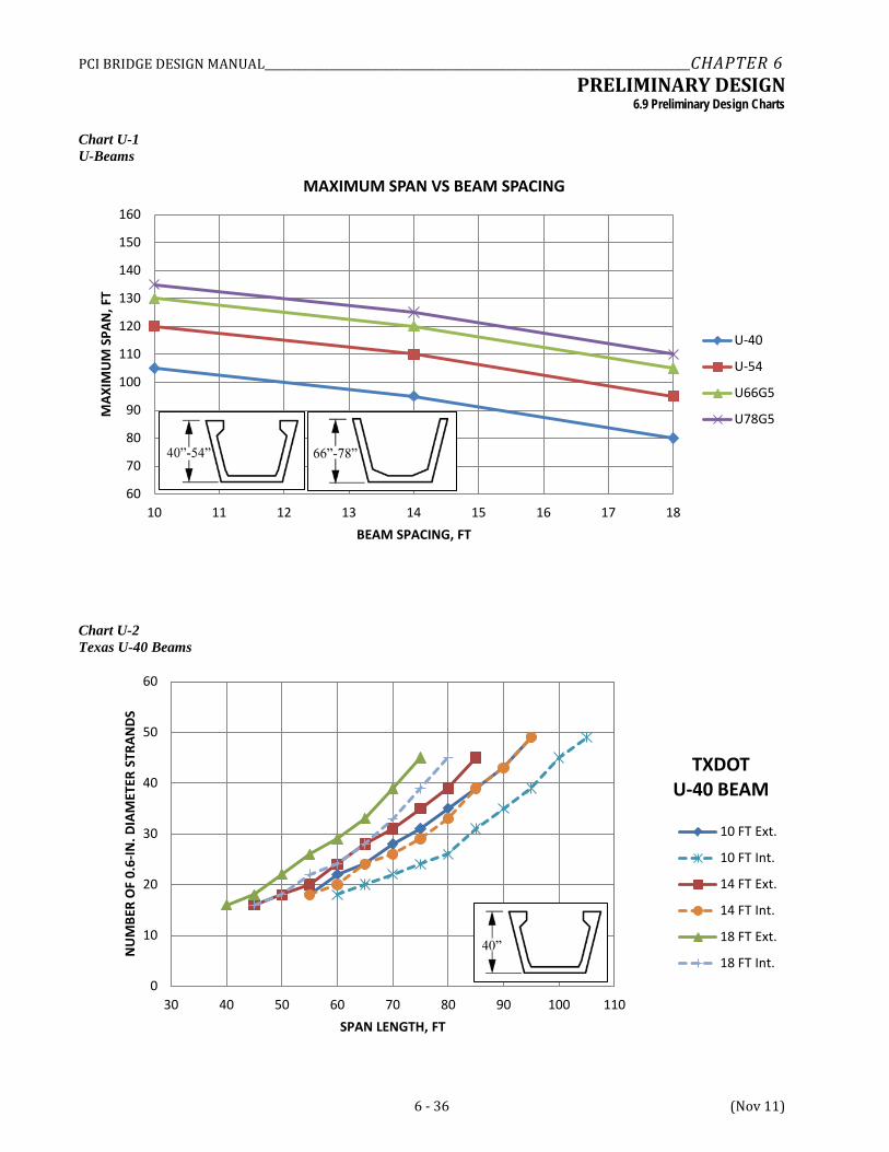
For composite U-beams, the overhang measured from the centerline of the exterior beam was selected as 6 ft. With precast section widths of 6 to 8 ft for common U-beams, this results in a physical overhang beyond the exterior web on the order of 2 to 3 ft, a reasonable dimension. The spacing of U-beams was chosen to vary from 10 to 18 ft. The minimum spacing of 10 ft reflects a reasonable minimum spacing given that the precast section will be 6 to 8 ft wide typically at its top. This is a near practical minimum beam spacing. At the upper end, a beam spacing of 18 ft was selected. This is the upper end of the limit of the empirical AASHTO live load distribution factors and results in a clear deck span between boxes of about 10 to 12 ft, still a reasonable slab span for conventionally reinforced decks and easily accommodated by traditional deck forming systems including stay-in-place precast deck panels.
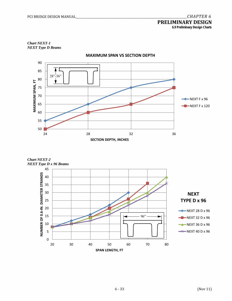
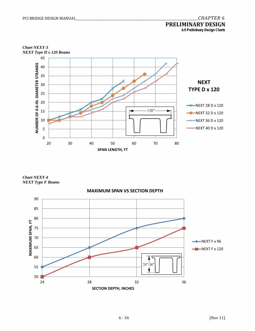
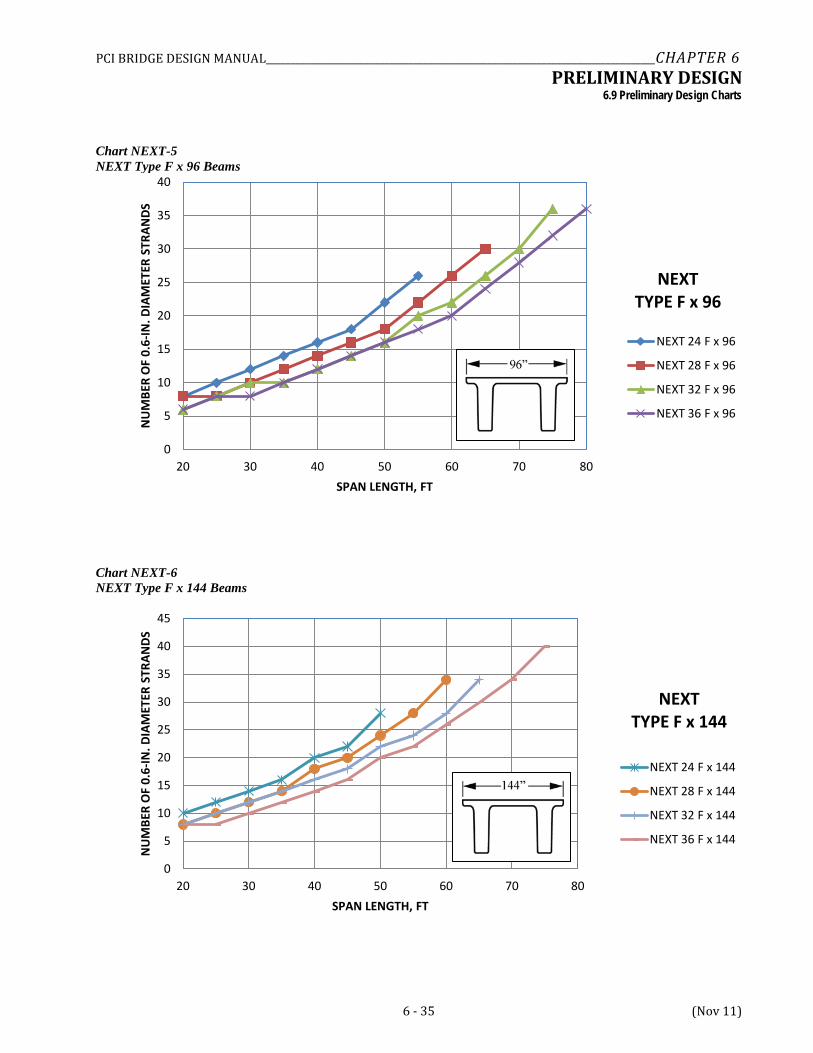
Two NEXT beam types were chosen for evaluation, Type D and Type F. The Type D section has a thick top flange (8 in.) that can serve directly as the structural slab for the bridge. The design considers that a 3-in.-thick asphalt wearing surface is used. The other beam type, Type F, has a 4-in.-thick top flange that primarily serves as a continuous stay-in-place form for a traditional 8-in.-thick composite cast-in-place deck with a future overlay allowance.
6.5.2.1 Live Loads The live load considered for the charts is the HL-93 loading with all designs based on a single span bridge. A random check of selected designs for the Type 3, 3S2 and 3-3 rating loads indicated that the HL-93 designs governed the design and resulted in designs with inventory and operating rating factors greater than 1.0 for the various notional rating vehicles. Live load moment and shear are distributed to the beams in accordance with the AASHTO empirical equations for live load distribution found in LRFD Section 4.6.2.2 with the exception that the rigid rotation model for exterior beams is not considered. The rigid rotation model is only stipulated for bridges with diaphragms and cross frames that are sufficient to induce a load distribution mechanism analogous to the rigid body distribution usually assumed for elements like pile groups or footings. For a prestressed concrete I-beam or bulb-tee section such as cross-section (k) in LRFD Table 4.6.2.2.1-1, the designer should consider whether the exterior diaphragms required by the specifications or agency policy are sufficient in number and stiffness to produce such behavior. If so, the design charts may prove to be unconservative for exterior beams in some instances and the designer should be aware that three potential exterior beam distribution factors might apply―the simple beam, AASHTO empirical, and rigid rotation model.
Since various types of beams and cross sections have been studied, a unique approach to live load distribution is required for each solution. The following load distribution models from LRFD Table 4.6.2.2.1-1 were considered in the development of the design graphs.
• For AASHTO I-beam and bulb-tee sections, cross-section Type (k) was used. • For spread box beams, cross-section Type (b) was used. • For U-beams, cross-section Type (c) was used. • For adjacent box beams with a cast-in-place concrete overlay, Type (f) was used. All adjacent box beams
were assumed to have a composite, cast-in-place concrete slab. Charts for non-composite box beams with an asphalt overlay were not developed.
• For deck bulb-tee bridges without transverse post-tensioning in the flanges, cross-section Type (j) was used.
• For double-tee NEXT Type D and F beams, cross-section (k) was used to be consistent with the PCI Northeast Chapter assumptions in developing the section and details. (see Appendix C)
6.5.2.2 Dead Loads The design of the first interior beam was performed assuming that the beam carries 50% of the weight of the barrier rail. A 42-in.-high single slope barrier rail was assumed, weighing approximately 0.500 kips/ft, with half of this load carried by the exterior beam and half by the first interior beam. The practice of distributing the parapet load to exterior and interior beams varies widely amongst engineers and agencies from even distribution to all beams to rules requiring a larger share of this load be carried by the exterior beam(s). For purposes of developing the design charts, it was assumed that the exterior beam carries 50% of the barrier rail and the first interior beam
PCI BRIDGE DESIGN MANUAL_______________________________________________________________________________CHAPTER 6 PRELIMINARY DESIGN
6.5.2.2 Dead Loads/6.5.2.4 Concrete Strength and Allowable Stresses
6 - 16 (Nov 11)
carries the remaining 50%. With heavy parapet loads, stiff beams, and relatively short overhangs, this approach is considered a reasonable approximation. Cast-in-place slab loads are assigned on a tributary basis. An allowance of 0.035 ksf is provided between gutter lines, uniformly carried by all beams, to provide for an additional wearing surface (DW) loading.
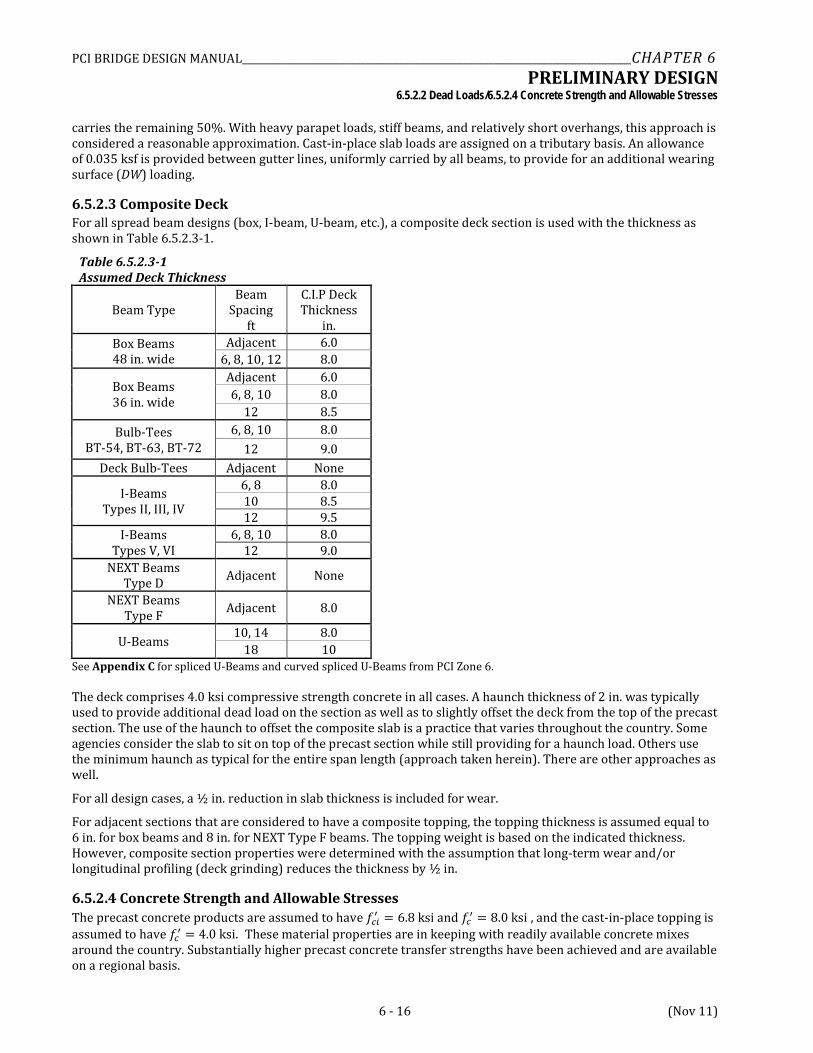
6.5.2.3 Composite Deck For all spread beam designs (box, I-beam, U-beam, etc.), a composite deck section is used with the thickness as shown in Table 6.5.2.3-1.
Table 6.5.2.3-1 Assumed Deck Thickness
Beam Type Beam
Spacing ft
C.I.P Deck Thickness
in. Box Beams 48 in. wide
Adjacent 6.0 6, 8, 10, 12 8.0
Box Beams 36 in. wide
Adjacent 6.0 6, 8, 10 8.0
12 8.5 Bulb-Tees
BT-54, BT-63, BT-72 6, 8, 10 8.0
12 9.0 Deck Bulb-Tees Adjacent None
I-Beams Types II, III, IV
6, 8 8.0 10 8.5 12 9.5
I-Beams Types V, VI
6, 8, 10 8.0 12 9.0
NEXT Beams Type D Adjacent None
NEXT Beams Type F Adjacent 8.0
U-Beams 10, 14 8.0
18 10 See Appendix C for spliced U-Beams and curved spliced U-Beams from PCI Zone 6.
The deck comprises 4.0 ksi compressive strength concrete in all cases. A haunch thickness of 2 in. was typically used to provide additional dead load on the section as well as to slightly offset the deck from the top of the precast section. The use of the haunch to offset the composite slab is a practice that varies throughout the country. Some agencies consider the slab to sit on top of the precast section while still providing for a haunch load. Others use the minimum haunch as typical for the entire span length (approach taken herein). There are other approaches as well.
For all design cases, a ½ in. reduction in slab thickness is included for wear.
For adjacent sections that are considered to have a composite topping, the topping thickness is assumed equal to 6 in. for box beams and 8 in. for NEXT Type F beams. The topping weight is based on the indicated thickness. However, composite section properties were determined with the assumption that long-term wear and/or longitudinal profiling (deck grinding) reduces the thickness by ½ in.
6.5.2.4 Concrete Strength and Allowable Stresses The precast concrete products are assumed to have 𝑓𝑐𝑖′ = 6.8 ksi and 𝑓𝑐′ = 8.0 ksi , and the cast-in-place topping is assumed to have 𝑓𝑐′ = 4.0 ksi. These material properties are in keeping with readily available concrete mixes around the country. Substantially higher precast concrete transfer strengths have been achieved and are available on a regional basis.
PCI BRIDGE DESIGN MANUAL_______________________________________________________________________________CHAPTER 6 PRELIMINARY DESIGN
6.6 Description of Design Charts/6.6.4 Controls
6 - 18 (Nov 11)
6.6 DESCRIPTION OF DESIGN CHARTS
6.6.1 Product Groups The design charts in Section 6.9 provide preliminary design information for different products grouped into several types. These include:
CHARTS PRODUCTS
Charts BB-1 through BB-10 AASHTO box beams
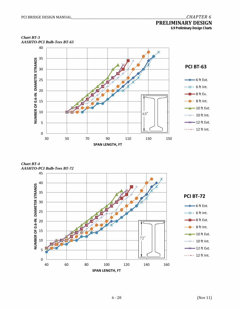
BT-1 through BT-4 AASHTO-PCI bulb-tees
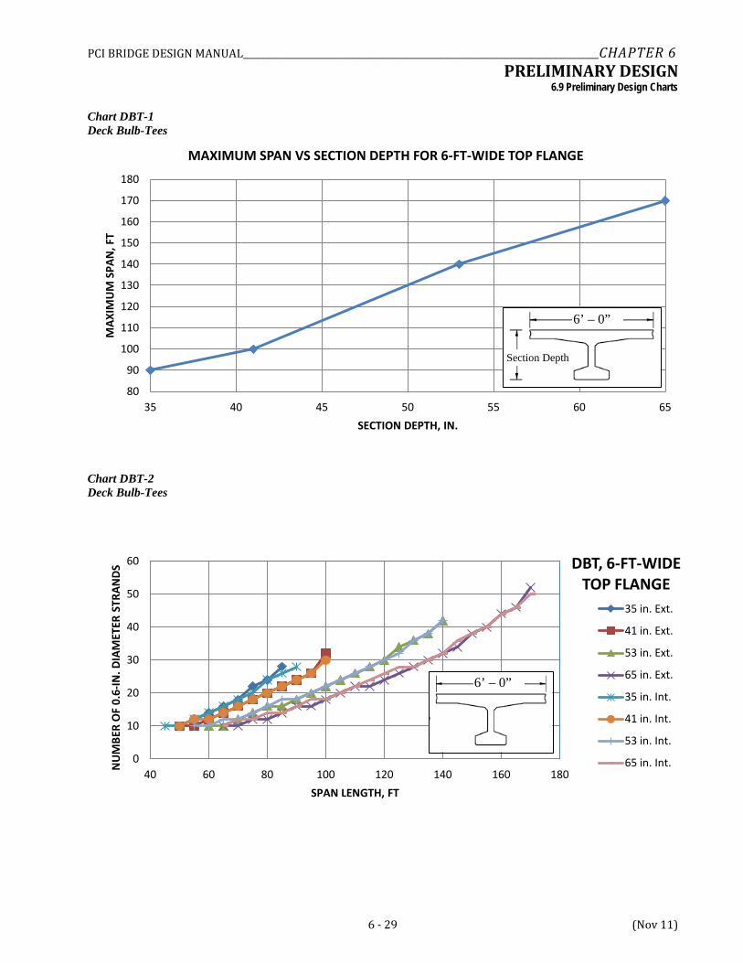
DBT-1 through DBT-2 Deck bulb-tees
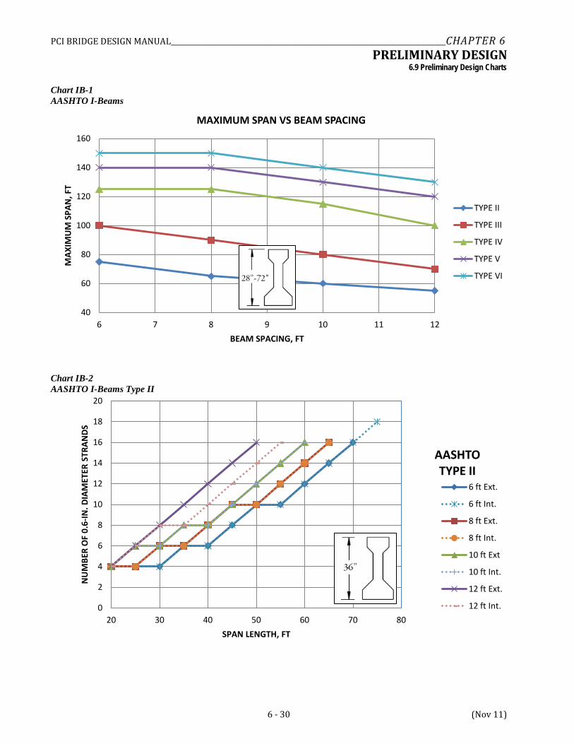
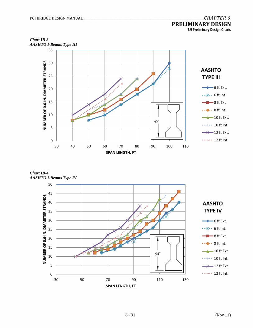
IB-1 through IB-6 AASHTO I-beams
NEXT-1 and NEXT-6 NEXT Double-tee beams
U-1 through U-5 U-Beams
(Geometric properties for products are given in Appendix B.)
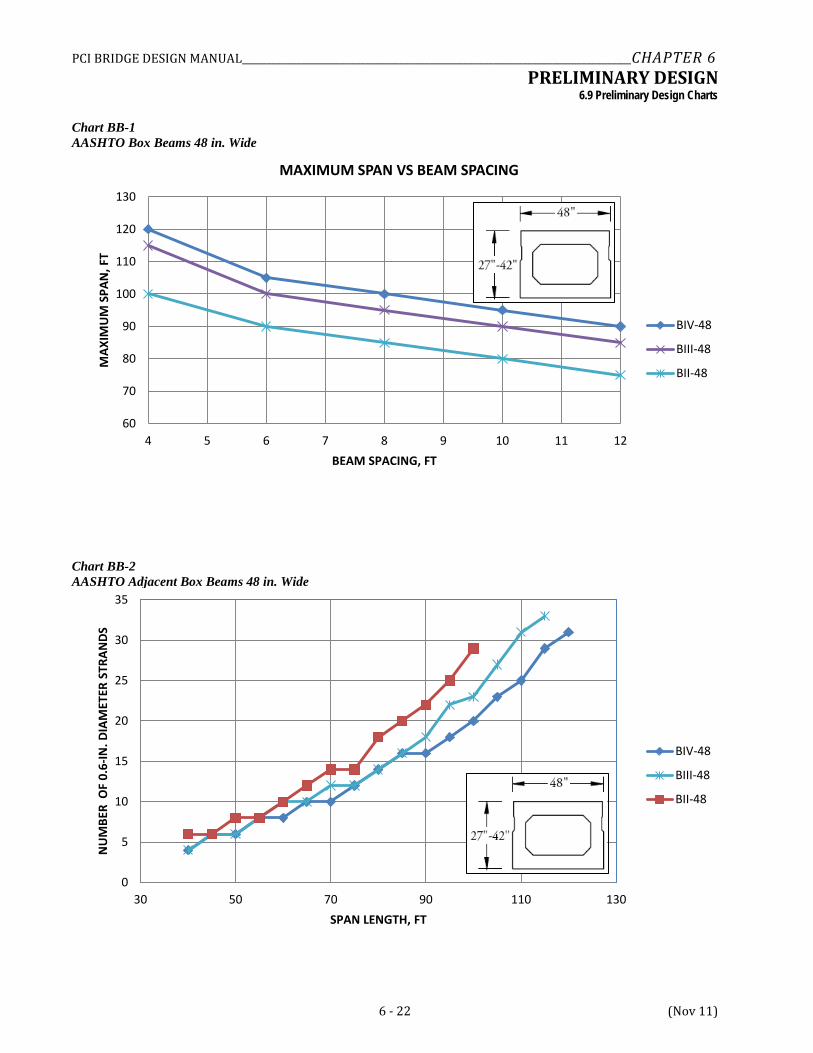
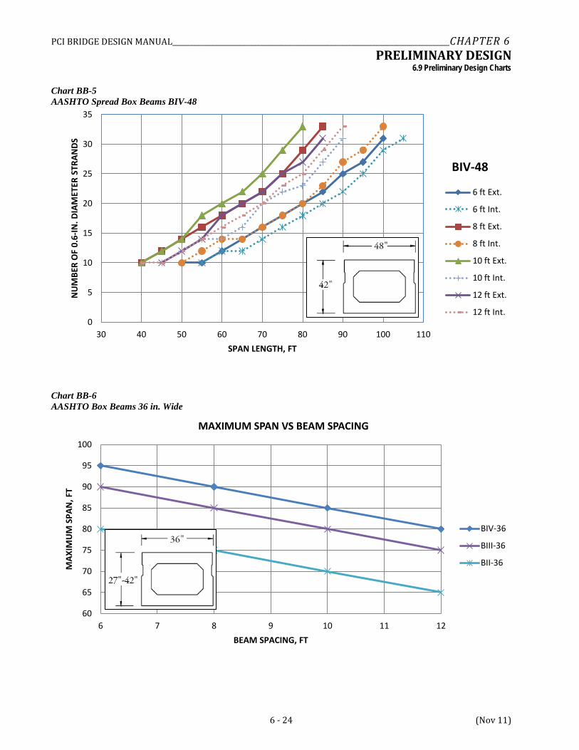
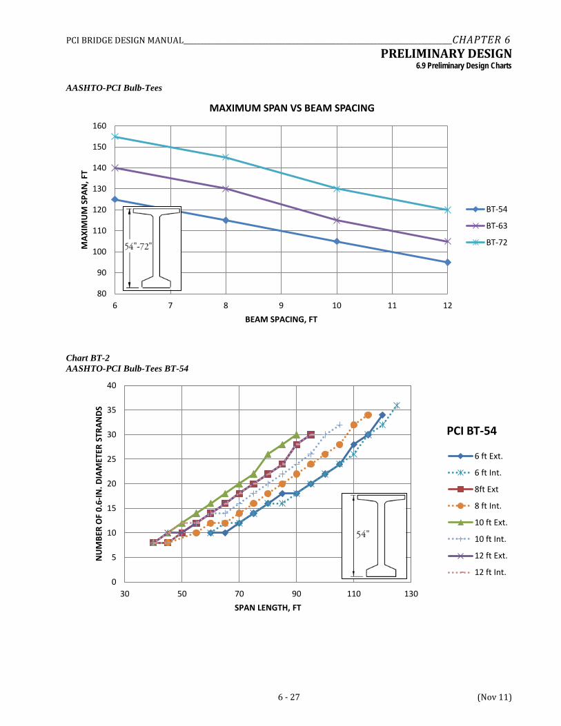
6.6.2 Maximum Spans Versus Spacings Within each group, the first chart, e.g. BB-1, BT-1,… etc., depicts the maximum attainable span versus member spacing for all member depths within the group. This type of chart is convenient to use in the early stages of design to identify product types, spacings, and approximate depths for the span length being considered.
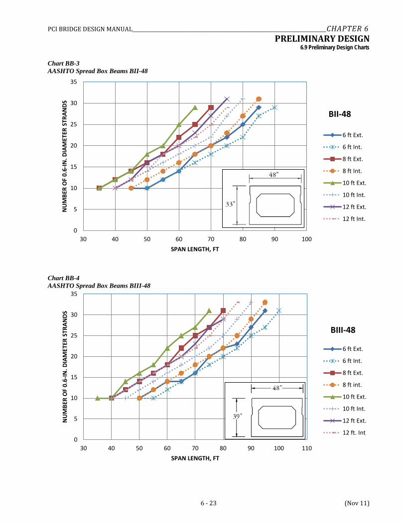
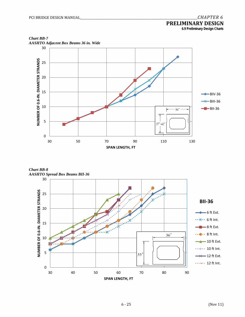
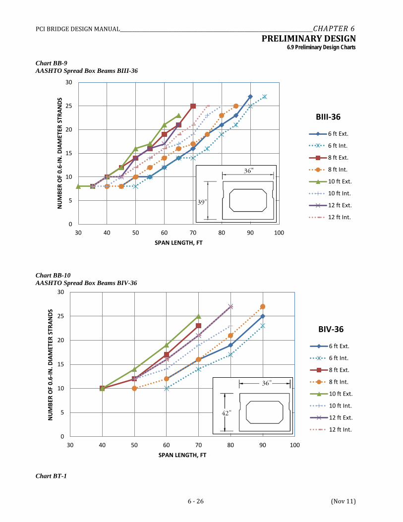
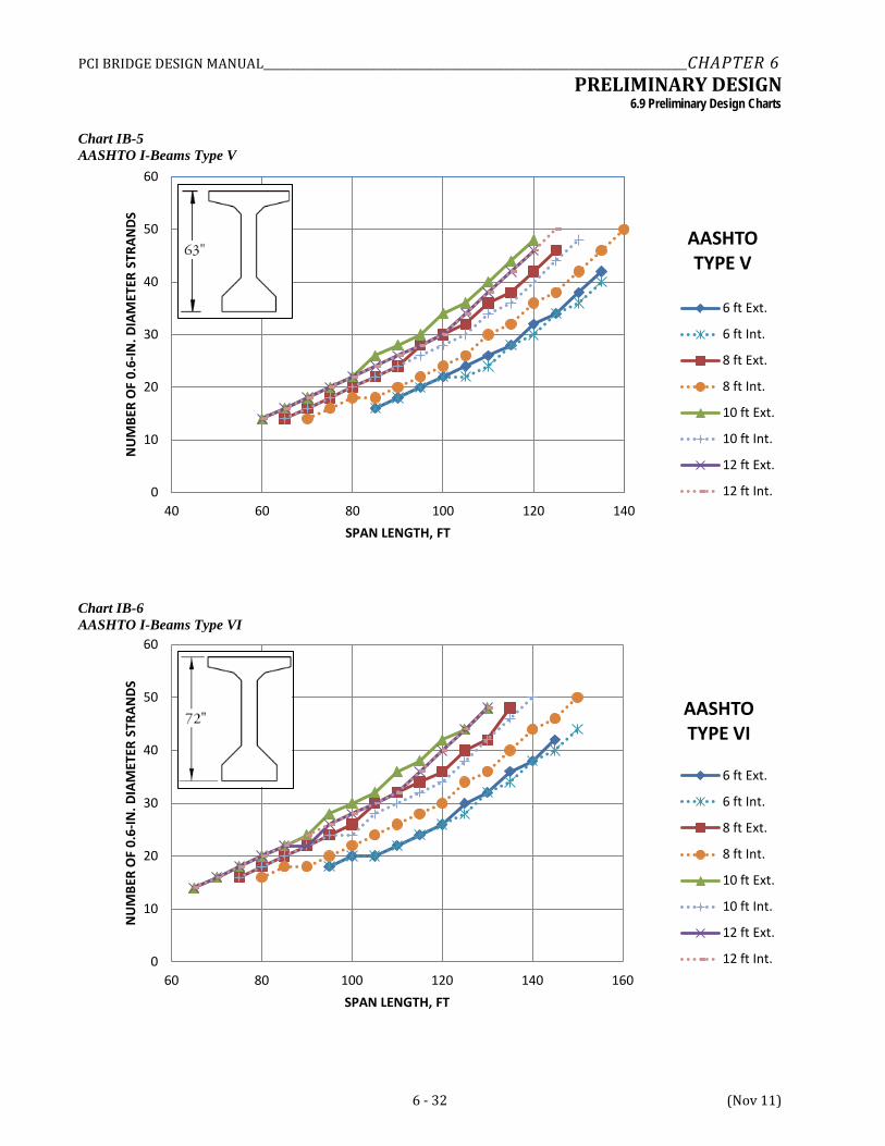
6.6.3 Number of Strands The remainder of the charts within each group give the number of strands needed for specified span lengths and beam spacings. This type of information is needed to: (1) develop an estimate of the final design requirements, and (2) to determine if the number of strands needed is within the prestressing bed capacity of local producers. Otherwise, the member depth, or spacing if applicable, must be adjusted.
In developing the charts, no attempt was made to judge whether or not the number of strands given is feasible for local production. The number of strands was strictly based on flexural stress or strength requirements. In some cases, e.g., shallow I-beams at wide spacing, shear capacity may require an unreasonable stirrup arrangement. A complete check should be made during final design.
It should be noted that all charts were based on providing the lowest possible center of gravity of strands in the midspan section. This is accomplished by filling the first (bottom) row to capacity before any strands can be placed in the second row, and so on.
6.6.4 Controls For each scenario, various potential controls were checked. In general, the maximum span was first established by satisfying the Strength I and Service III limit states. When strands could no longer be added to the section, or doing so did not increase span capacity, the practical maximum span was established. However this was usually a large number of strands for a particular beam section. Checks of stress at transfer were also performed. To mitigate the high stresses in the transfer region, the use of harping (with a hold down at 0.4L) or debonding was used to control the beam end stresses. Maximum debonding limits of 40% of the strands in a row and 25% of the total number of strands were enforced with the exception that if the number of debonded strands was only one strand over the maximum due to rounding, that was considered an acceptable solution. The charts do not indicate the nature of the control but generally for narrower beam spacings the trend was for Service III to govern and for wider spacing, longer spans, Strength I was a common control. Most of the intermediate to longer spans required some debonding or harping to control the end zone stresses.
PCI BRIDGE DESIGN MANUAL_______________________________________________________________________________CHAPTER 6 PRELIMINARY DESIGN
6.7 Preliminary Design Examples/6.7.2 Preliminary Design Example No. 2
6 - 19 (Nov 11)
6.7 PRELIMINARY DESIGN EXAMPLES
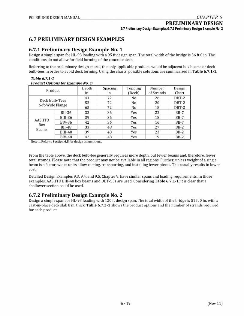
6.7.1 Preliminary Design Example No. 1 Design a simple span for HL-93 loading with a 95 ft design span. The total width of the bridge is 36 ft 0 in. The conditions do not allow for field forming of the concrete deck.
Referring to the preliminary design charts, the only applicable products would be adjacent box beams or deck bulb-tees in order to avoid deck forming. Using the charts, possible solutions are summarized in Table 6.7.1-1.
Table 6.7.1-1 Product Options for Example No. 11
Product Depth in.
Spacing in.
Topping (Deck)
Number of Strands
Design Chart
Deck Bulb-Tees 6-ft-Wide Flange
41 72 No 26 DBT-2 53 72 No 20 DBT-2 65 72 No 18 DBT-2
AASHTO Box
Beams
BII-36 33 36 Yes 22 BB-7 BIII-36 39 36 Yes 18 BB-7 BIV-36 42 36 Yes 16 BB-7 BII-48 33 48 Yes 27 BB-2 BIII-48 39 48 Yes 23 BB-2 BIV-48 42 48 Yes 19 BB-2
Note 1. Refer to Section 6.5 for design assumptions.
From the table above, the deck bulb-tee generally requires more depth, but fewer beams and, therefore, fewer total strands. Please note that the product may not be available in all regions. Further, unless weight of a single beam is a factor, wider units allow casting, transporting, and installing fewer pieces. This usually results in lower cost.
Detailed Design Examples 9.3, 9.4, and 9.5, Chapter 9, have similar spans and loading requirements. In those examples, AASHTO BIII-48 box beams and DBT-53s are used. Considering Table 6.7.1-1, it is clear that a shallower section could be used.
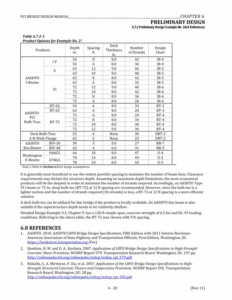
6.7.2 Preliminary Design Example No. 2 Design a simple span for HL-93 loading with 120 ft design span. The total width of the bridge is 51 ft 0 in. with a cast-in-place deck slab 8 in. thick. Table 6.7.2-1 shows the product options and the number of strands required for each product.
PCI BRIDGE DESIGN MANUAL_______________________________________________________________________________CHAPTER 6 PRELIMINARY DESIGN
6.7.2 Preliminary Design Example No. 2/6.8 References
6 - 20 (Nov 11)
Table 6.7.2-1 Product Options for Example No. 21
Products Depth in.
Spacing ft
Deck Thickness
in.
Number of Strands
Design Chart
AASHTO I-Beams
I V 54 8 8.0 42 IB-4 54 6 8.0 36 IB-4
V 63 12 9.0 46 IB-5 63 10 8.0 48 IB-5
VI
63 8 8.0 42 IB-5 63 6 8.0 32 IB-5 72 12 9.0 40 IB-6 72 10 8.0 42 IB-6 72 8 8.0 36 IB-6 72 6 8.0 26 IB-6
AASHTO-PCI
Bulb-Tees
BT-54 54 6 8.0 34 BT-2 BT-63 63 6 8.0 28 BT-3
BT-72
72 6 8.0 24 BT-4 72 8 8.0 34 BT-4 72 10 8.0 38 BT-4 72 12 9.0 36 BT-4
Deck Bulb-Tees 6-ft-Wide Flange
53 6 None 30 DBT-2 65 6 None 23 DBT-2
AASHTO Box Beams
BIV-36 39 3 6.0 27 BB-7 BIV-48 42 4 6.0 31 BB-5
Washington U-Beams
U66G5 66 10 8.0 47 U-4
U78G5 78 14 8.0 49 U-5 78 10 8.0 43 U-5
Note 1. Refer to Section 6.5 for design assumptions.
It is generally most beneficial to use the widest possible spacing to minimize the number of beam lines. Clearance requirements may dictate the structure depth. Assuming no maximum depth limitations, the most economical products will be the deepest in order to minimize the number of strands required. Accordingly, an AASHTO Type VI I-beam or 72-in.-deep bulb-tee (BT-72) at 12 ft spacing are recommended. However, since the bulb-tee is a lighter section and the number of strands required (36 strands) is less, a BT-72 at 12 ft spacing is a more efficient solution. A deck bulb-tee can be utilized for this bridge if the product is locally available. An AASHTO box beam is also suitable if the superstructure depth needs to be relatively shallow. Detailed Design Example 9.3, Chapter 9, has a 120-ft simple span, concrete strength of 6.5 ksi and HL-93 loading conditions. Referring to the above table, the BT-72 was chosen with 9 ft spacing.
6.8 REFERENCES 1. AASHTO. 2010. AASHTO LRFD Bridge Design Specifications, Fifth Edition with 2011 Interim Revisions.
American Association of State Highway and Transportation Officials, First Edition, Washington, DC. https://bookstore.transportation.org (Fee)
2. Hawkins, N. M. and D. A., Kuchma, 2007. Application of LRFD Bridge Design Specifications to High-Strength Concrete: Shear Provisions. NCHRP Report 579. Transportation Research Board. Washington, DC. 197 pp. http://onlinepubs.trb.org/onlinepubs/nchrp/nchrp_rpt_579.pdf
3. Rizkalla, S., A. Mirmiran, P. Zia, et al. 2007. Application of the LRFD Bridge Design Specifications to High-Strength Structural Concrete: Flexure and Compression Provisions. NCHRP Report 595. Transportation Research Board. Washington, DC. 28 pp. http://onlinepubs.trb.org/onlinepubs/nchrp/nchrp_rpt_595.pdf
PCI BRIDGE DESIGN MANUAL_______________________________________________________________________________CHAPTER 6 PRELIMINARY DESIGN
6.8 References/6.9 Preliminary Design Charts
6 - 21 (Nov 11)
4. Ramirez, J. A. and B. W. Russell. 2008. Transfer, Development, and Splice Length for Strand/Reinforcement in High-Strength Concrete. NCHRP Report 603. Transportation Research Board. Washington, DC. 122 pp. http://onlinepubs.trb.org/onlinepubs/nchrp/nchrp_rpt_603.pdf
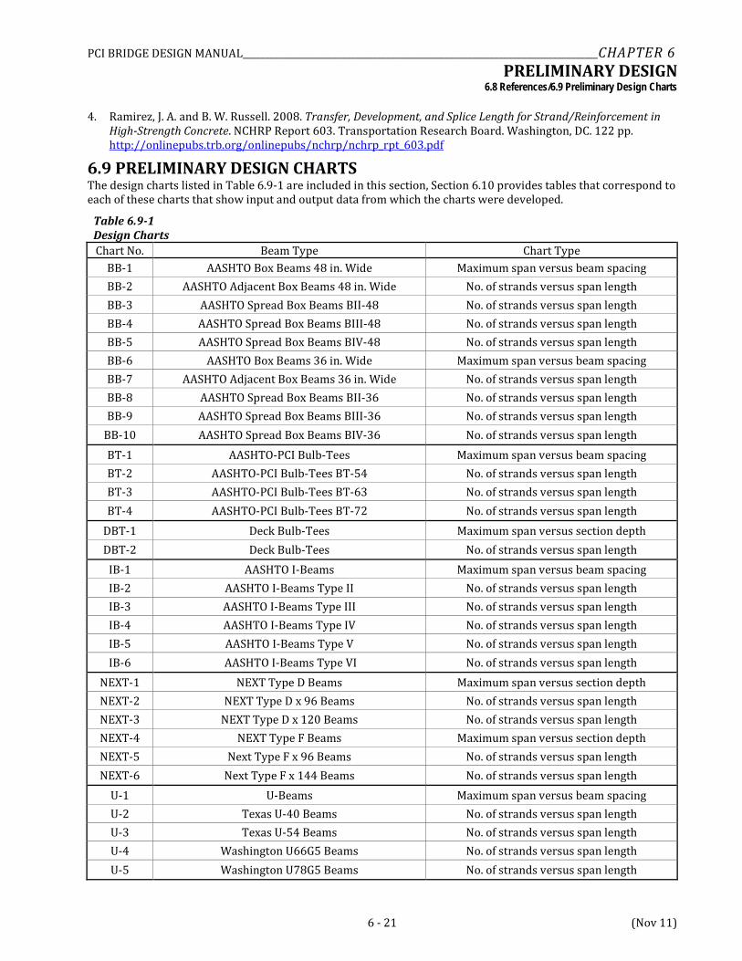
6.9 PRELIMINARY DESIGN CHARTS The design charts listed in Table 6.9-1 are included in this section, Section 6.10 provides tables that correspond to each of these charts that show input and output data from which the charts were developed.
Table 6.9-1 Design Charts Chart No. Beam Type Chart Type
BB-1 AASHTO Box Beams 48 in. Wide Maximum span versus beam spacing BB-2 AASHTO Adjacent Box Beams 48 in. Wide No. of strands versus span length BB-3 AASHTO Spread Box Beams BII-48 No. of strands versus span length BB-4 AASHTO Spread Box Beams BIII-48 No. of strands versus span length BB-5 AASHTO Spread Box Beams BIV-48 No. of strands versus span length BB-6 AASHTO Box Beams 36 in. Wide Maximum span versus beam spacing BB-7 AASHTO Adjacent Box Beams 36 in. Wide No. of strands versus span length BB-8 AASHTO Spread Box Beams BII-36 No. of strands versus span length BB-9 AASHTO Spread Box Beams BIII-36 No. of strands versus span length
BB-10 AASHTO Spread Box Beams BIV-36 No. of strands versus span length BT-1 AASHTO-PCI Bulb-Tees Maximum span versus beam spacing BT-2 AASHTO-PCI Bulb-Tees BT-54 No. of strands versus span length BT-3 AASHTO-PCI Bulb-Tees BT-63 No. of strands versus span length BT-4 AASHTO-PCI Bulb-Tees BT-72 No. of strands versus span length
DBT-1 Deck Bulb-Tees Maximum span versus section depth DBT-2 Deck Bulb-Tees No. of strands versus span length
IB-1 AASHTO I-Beams Maximum span versus beam spacing IB-2 AASHTO I-Beams Type II No. of strands versus span length IB-3 AASHTO I-Beams Type III No. of strands versus span length IB-4 AASHTO I-Beams Type IV No. of strands versus span length IB-5 AASHTO I-Beams Type V No. of strands versus span length IB-6 AASHTO I-Beams Type VI No. of strands versus span length
NEXT-1 NEXT Type D Beams Maximum span versus section depth NEXT-2 NEXT Type D x 96 Beams No. of strands versus span length NEXT-3 NEXT Type D x 120 Beams No. of strands versus span length NEXT-4 NEXT Type F Beams Maximum span versus section depth NEXT-5 Next Type F x 96 Beams No. of strands versus span length NEXT-6 Next Type F x 144 Beams No. of strands versus span length
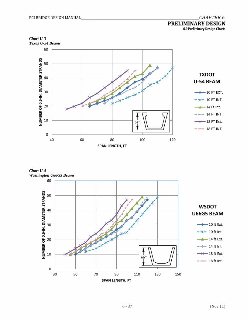
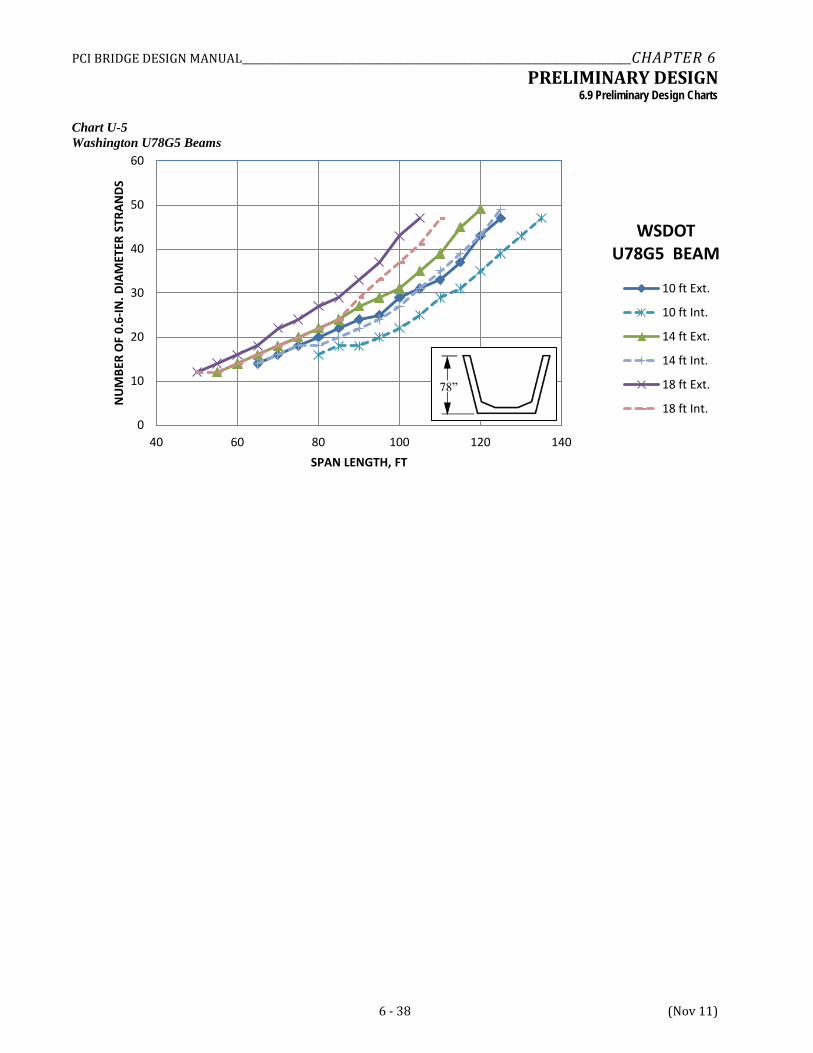
U-1 U-Beams Maximum span versus beam spacing U-2 Texas U-40 Beams No. of strands versus span length U-3 Texas U-54 Beams No. of strands versus span length U-4 Washington U66G5 Beams No. of strands versus span length U-5 Washington U78G5 Beams No. of strands versus span length
PCI BRIDGE DESIGN MANUAL_______________________________________________________________________________CHAPTER 6 PRELIMINARY DESIGN
6.9 Preliminary Design Charts
6 - 22 (Nov 11)
Chart BB-1 AASHTO Box Beams 48 in. Wide
Chart BB-2 AASHTO Adjacent Box Beams 48 in. Wide
0
5
10
15
20
25
30
35
30 50 70 90 110 130
NU
MBE
R O
F 0.
6-IN
. DIA
MET
ER S
TRAN
DS
SPAN LENGTH, FT
BIV-48
BIII-48
BII-48
60
70
80
90
100
110
120
130
4 5 6 7 8 9 10 11 12
MAX
IMU
M S
PAN
, FT
BEAM SPACING, FT
MAXIMUM SPAN VS BEAM SPACING
BIV-48
BIII-48
BII-48
PCI BRIDGE DESIGN MANUAL_______________________________________________________________________________CHAPTER 6 PRELIMINARY DESIGN
6.9 Preliminary Design Charts
6 - 23 (Nov 11)
Chart BB-3 AASHTO Spread Box Beams BII-48
Chart BB-4 AASHTO Spread Box Beams BIII-48
0
5
10
15
20
25
30
35
30 40 50 60 70 80 90 100
NU
MBE
R O
F 0.
6-IN
. DIA
MET
ER S
TRAN
DS
SPAN LENGTH, FT
BII-48
6 ft Ext.
6 ft Int.
8 ft Ext.
8 ft Int.
10 ft Ext.
10 ft Int.
12 ft Ext.
12 ft Int.
0
5
10
15
20
25
30
35
30 40 50 60 70 80 90 100 110
NU
MBE
R O
F 0.
6-IN
. DIA
MET
ER S
TRAN
DS
SPAN LENGTH, FT
BIII-48
6 ft Ext.
6 ft Int.
8 ft Ext.
8 ft int.
10 ft Ext.
10 ft Int.
12 ft Ext.
12 ft. Int
PCI BRIDGE DESIGN MANUAL_______________________________________________________________________________CHAPTER 6 PRELIMINARY DESIGN
6.9 Preliminary Design Charts
6 - 24 (Nov 11)
Chart BB-5 AASHTO Spread Box Beams BIV-48
Chart BB-6 AASHTO Box Beams 36 in. Wide
60
65
70
75
80
85
90
95
100
6 7 8 9 10 11 12
MAX
IMU
M S
PAN
, FT
BEAM SPACING, FT
MAXIMUM SPAN VS BEAM SPACING
BIV-36
BIII-36
BII-36
0
5
10
15
20
25
30
35
30 40 50 60 70 80 90 100 110
NU
MBE
R O
F 0.
6-IN
. DIA
MET
ER S
TRAN
DS
SPAN LENGTH, FT
BIV-48
6 ft Ext.
6 ft Int.
8 ft Ext.
8 ft Int.
10 ft Ext.
10 ft Int.
12 ft Ext.
12 ft Int.
PCI BRIDGE DESIGN MANUAL_______________________________________________________________________________CHAPTER 6 PRELIMINARY DESIGN
6.9 Preliminary Design Charts
6 - 25 (Nov 11)
Chart BB-7 AASHTO Adjacent Box Beams 36 in. Wide
Chart BB-8 AASHTO Spread Box Beams BII-36
0
5
10
15
20
25
30
30 50 70 90 110 130
NU
MBE
R O
F 0.
6-IN
. DIA
MET
ER S
TRAN
DS
SPAN LENGTH, FT
BIV-36
BIII-36
BII-36
0
5
10
15
20
25
30
30 40 50 60 70 80 90
NU
MBE
R O
F 0.
6-IN
. DIA
MET
ER S
TRAN
DS
SPAN LENGTH, FT
BII-36
6 ft Ext.
6 ft Int.
8 ft Ext.
8 ft Int.
10 ft Ext.
10 ft Int.
12 ft Ext.
12 ft Int.
PCI BRIDGE DESIGN MANUAL_______________________________________________________________________________CHAPTER 6 PRELIMINARY DESIGN
6.9 Preliminary Design Charts
6 - 26 (Nov 11)
Chart BB-9 AASHTO Spread Box Beams BIII-36
Chart BB-10 AASHTO Spread Box Beams BIV-36
Chart BT-1
0
5
10
15
20
25
30
30 40 50 60 70 80 90 100
NU
MBE
R O
F 0.
6-IN
. DIA
MET
ER S
TRAN
DS
SPAN LENGTH, FT
BIII-36
6 ft Ext.
6 ft Int.
8 ft Ext.
8 ft Int.
10 ft Ext.
10 ft Int.
12 ft Ext.
12 ft Int.
0
5
10
15
20
25
30
30 40 50 60 70 80 90 100
NU
MBE
R O
F 0.
6-IN
. DIA
MET
ER S
TRAN
DS
SPAN LENGTH, FT
BIV-36
6 ft Ext.
6 ft Int.
8 ft Ext.
8 ft Int.
10 ft Ext.
10 ft Int.
12 ft Ext.
12 ft Int.
PCI BRIDGE DESIGN MANUAL_______________________________________________________________________________CHAPTER 6 PRELIMINARY DESIGN
6.9 Preliminary Design Charts
6 - 27 (Nov 11)
AASHTO-PCI Bulb-Tees
Chart BT-2 AASHTO-PCI Bulb-Tees BT-54
80
90
100
110
120
130
140
150
160
6 7 8 9 10 11 12
MAX
IMU
M S
PAN
, FT
BEAM SPACING, FT
MAXIMUM SPAN VS BEAM SPACING
BT-54
BT-63
BT-72
0
5
10
15
20
25
30
35
40
30 50 70 90 110 130
NU
MBE
R O
F 0.
6-IN
. DIA
MET
ER S
TRAN
DS
SPAN LENGTH, FT
PCI BT-54
6 ft Ext.
6 ft Int.
8ft Ext
8 ft Int.
10 ft Ext.
10 ft Int.
12 ft Ext.
12 ft Int.
PCI BRIDGE DESIGN MANUAL_______________________________________________________________________________CHAPTER 6 PRELIMINARY DESIGN
6.9 Preliminary Design Charts
6 - 28 (Nov 11)
Chart BT-3 AASHTO-PCI Bulb-Tees BT-63
Chart BT-4 AASHTO-PCI Bulb-Tees BT-72
0
5
10
15
20
25
30
35
40
30 50 70 90 110 130 150
NU
MBE
R O
F 0.
6-IN
. DIA
MET
ER S
TRAN
DS
SPAN LENGTH, FT
PCI BT-63
6 ft Ext.
6 ft Int.
8 ft Ex.
8 ft Int.
10 ft Ext.
10 ft Int.
12 ft Ext.
12 ft Int.
0
5
10
15
20
25
30
35
40
45
40 60 80 100 120 140 160
NU
MBE
R O
F 0.
6-IN
. DIA
MET
ER S
TRAN
DS
SPAN LENGTH, FT
PCI BT-72
6 ft Ext.
6 ft Int.
8 ft Ext.
8 ft Int.
10 ft Ext.
10 ft Int.
12 ft Ext.
12 ft Int.
PCI BRIDGE DESIGN MANUAL_______________________________________________________________________________CHAPTER 6 PRELIMINARY DESIGN
6.9 Preliminary Design Charts
6 - 29 (Nov 11)
Chart DBT-1 Deck Bulb-Tees
Chart DBT-2 Deck Bulb-Tees
0
10
20
30
40
50
60
40 60 80 100 120 140 160 180
NU
MBE
R O
F 0.
6-IN
. DIA
MET
ER S
TRAN
DS
SPAN LENGTH, FT
DBT, 6-FT-WIDE TOP FLANGE
35 in. Ext.
41 in. Ext.
53 in. Ext.
65 in. Ext.
35 in. Int.
41 in. Int.
53 in. Int.
65 in. Int.
80
90
100
110
120
130
140
150
160
170
180
35 40 45 50 55 60 65
MAX
IMU
M S
PAN
, FT
SECTION DEPTH, IN.
MAXIMUM SPAN VS SECTION DEPTH FOR 6-FT-WIDE TOP FLANGE
Section Depth
6’ – 0”
6’ – 0”
PCI BRIDGE DESIGN MANUAL_______________________________________________________________________________CHAPTER 6 PRELIMINARY DESIGN
6.9 Preliminary Design Charts
6 - 30 (Nov 11)
Chart IB-1 AASHTO I-Beams
Chart IB-2 AASHTO I-Beams Type II
40
60
80
100
120
140
160
6 7 8 9 10 11 12
MAX
IMU
M S
PAN
, FT
BEAM SPACING, FT
MAXIMUM SPAN VS BEAM SPACING
TYPE II
TYPE III
TYPE IV
TYPE V
TYPE VI
0
2
4
6
8
10
12
14
16
18
20
20 30 40 50 60 70 80
NU
MBE
R O
F 0.
6-IN
. DIA
MET
ER S
TRAN
DS
SPAN LENGTH, FT
AASHTO TYPE II
6 ft Ext.
6 ft Int.
8 ft Ext.
8 ft Int.
10 ft Ext
10 ft Int.
12 ft Ext.
12 ft Int.
PCI BRIDGE DESIGN MANUAL_______________________________________________________________________________CHAPTER 6 PRELIMINARY DESIGN
6.9 Preliminary Design Charts
6 - 31 (Nov 11)
Chart IB-3 AASHTO I-Beams Type III
Chart IB-4 AASHTO I-Beams Type IV
0
5
10
15
20
25
30
35
30 40 50 60 70 80 90 100 110
NU
MBE
R O
F 0.
6-IN
. DIA
MET
ER S
TRAN
DS
SPAN LENGTH, FT
AASHTO TYPE III
6 ft Ext.
6 ft Int.
8 ft Ext
8 ft Int.
10 ft Ext.
10 ft Int.
12 ft Ext.
12 ft Int.
0
5
10
15
20
25
30
35
40
45
50
30 50 70 90 110 130
NU
MBE
R O
F 0.
6-IN
. DIA
MET
ER S
TRAN
DS
SPAN LENGTH, FT
AASHTO TYPE IV
6 ft Ext.
6 ft Int.
8 ft Ext.
8 ft Int.
10 ft Ext.
10 ft Int.
12 ft Ext.
12 ft Int.
PCI BRIDGE DESIGN MANUAL_______________________________________________________________________________CHAPTER 6 PRELIMINARY DESIGN
6.9 Preliminary Design Charts
6 - 32 (Nov 11)
Chart IB-5 AASHTO I-Beams Type V
Chart IB-6 AASHTO I-Beams Type VI
0
10
20
30
40
50
60
40 60 80 100 120 140
NU
MBE
R O
F 0.
6-IN
. DIA
MET
ER S
TRAN
DS
SPAN LENGTH, FT
AASHTO TYPE V
6 ft Ext.
6 ft Int.
8 ft Ext.
8 ft Int.
10 ft Ext.
10 ft Int.
12 ft Ext.
12 ft Int.
0
10
20
30
40
50
60
60 80 100 120 140 160
NU
MBE
R O
F 0.
6-IN
. DIA
MET
ER S
TRAN
DS
SPAN LENGTH, FT
AASHTO TYPE VI
6 ft Ext.
6 ft Int.
8 ft Ext.
8 ft Int.
10 ft Ext.
10 ft Int.
12 ft Ext.
12 ft Int.
PCI BRIDGE DESIGN MANUAL_______________________________________________________________________________CHAPTER 6 PRELIMINARY DESIGN
6.9 Preliminary Design Charts
6 - 33 (Nov 11)
Chart NEXT-1 NEXT Type D Beams
Chart NEXT-2 NEXT Type D x 96 Beams
50
55
60
65
70
75
80
85
90
24 28 32 36
MAX
IMU
M S
PAN
, FT
SECTION DEPTH, INCHES
MAXIMUM SPAN VS SECTION DEPTH
NEXT F x 96
NEXT F x 120
0
5
10
15
20
25
30
35
40
45
20 30 40 50 60 70 80
NU
MBE
R O
F 0.
6-IN
. DIA
MET
ER S
TRAN
DS
SPAN LENGTH, FT
NEXT TYPE D x 96
NEXT 28 D x 96
NEXT 32 D x 96
NEXT 36 D x 96
NEXT 40 D x 96
PCI BRIDGE DESIGN MANUAL_______________________________________________________________________________CHAPTER 6 PRELIMINARY DESIGN
6.9 Preliminary Design Charts
6 - 34 (Nov 11)
Chart NEXT-3 NEXT Type D x 120 Beams
Chart NEXT-4 NEXT Type F Beams
0
5
10
15
20
25
30
35
40
45
20 30 40 50 60 70 80
NU
MBE
R O
F 0.
6-IN
. DIA
MET
ER S
TRAN
DS
SPAN LENGTH, FT
NEXT TYPE D x 120
NEXT 28 D x 120
NEXT 32 D x 120
NEXT 36 D x 120
NEXT 40 D x 120
50
55
60
65
70
75
80
85
90
24 28 32 36
MAX
IMU
M S
PAN
, FT
SECTION DEPTH, INCHES
MAXIMUM SPAN VS SECTION DEPTH
NEXT F x 96
NEXT F x 120
PCI BRIDGE DESIGN MANUAL_______________________________________________________________________________CHAPTER 6 PRELIMINARY DESIGN
6.9 Preliminary Design Charts
6 - 35 (Nov 11)
Chart NEXT-5 NEXT Type F x 96 Beams
Chart NEXT-6 NEXT Type F x 144 Beams
0
5
10
15
20
25
30
35
40
20 30 40 50 60 70 80
NU
MBE
R O
F 0.
6-IN
. DIA
MET
ER S
TRAN
DS
SPAN LENGTH, FT
NEXT TYPE F x 96
NEXT 24 F x 96
NEXT 28 F x 96
NEXT 32 F x 96
NEXT 36 F x 96
0
5
10
15
20
25
30
35
40
45
20 30 40 50 60 70 80
NU
MBE
R O
F 0.
6-IN
. DIA
MET
ER S
TRAN
DS
SPAN LENGTH, FT
NEXT TYPE F x 144
NEXT 24 F x 144
NEXT 28 F x 144
NEXT 32 F x 144
NEXT 36 F x 144
PCI BRIDGE DESIGN MANUAL_______________________________________________________________________________CHAPTER 6 PRELIMINARY DESIGN
6.9 Preliminary Design Charts
6 - 36 (Nov 11)
Chart U-1 U-Beams
Chart U-2 Texas U-40 Beams
60
70
80
90
100
110
120
130
140
150
160
10 11 12 13 14 15 16 17 18
MAX
IMU
M S
PAN
, FT
BEAM SPACING, FT
MAXIMUM SPAN VS BEAM SPACING
U-40
U-54
U66G5
U78G5
0
10
20
30
40
50
60
30 40 50 60 70 80 90 100 110
NU
MBE
R O
F 0.
6-IN
. DIA
MET
ER S
TRAN
DS
SPAN LENGTH, FT
TXDOT U-40 BEAM
10 FT Ext.
10 FT Int.
14 FT Ext.
14 FT Int.
18 FT Ext.
18 FT Int.
PCI BRIDGE DESIGN MANUAL_______________________________________________________________________________CHAPTER 6 PRELIMINARY DESIGN
6.9 Preliminary Design Charts
6 - 37 (Nov 11)
Chart U-3 Texas U-54 Beams
Chart U-4 Washington U66G5 Beams
0
10
20
30
40
50
60
40 60 80 100 120
NU
MBE
R O
F 0.
6-IN
. DIA
MET
ER S
TRAN
DS
SPAN LENGTH, FT
TXDOT U-54 BEAM
10 FT EXT.
10 FT INT.
14 Ft Int.
14 FT INT.
18 FT Ext.
18 FT INT.
0
10
20
30
40
50
60
30 50 70 90 110 130 150
NU
MBE
R O
F 0.
6-IN
. DIA
MET
ER S
TRAN
DS
SPAN LENGTH, FT
WSDOT U66G5 BEAM
10 ft Ext.
10 ft Int.
14 ft Ext.
14 ft Int
18 ft Ext.
18 ft Int.
PCI BRIDGE DESIGN MANUAL_______________________________________________________________________________CHAPTER 6 PRELIMINARY DESIGN
6.9 Preliminary Design Charts
6 - 38 (Nov 11)
Chart U-5 Washington U78G5 Beams
0
10
20
30
40
50
60
40 60 80 100 120 140
NU
MBE
R O
F 0.
6-IN
. DIA
MET
ER S
TRAN
DS
SPAN LENGTH, FT
WSDOT U78G5 BEAM
10 ft Ext.
10 ft Int.
14 ft Ext.
14 ft Int.
18 ft Ext.
18 ft Int.
PCI BRIDGE DESIGN MANUAL_______________________________________________________________________________CHAPTER 6 PRELIMINARY DESIGN
6.10 Preliminary Design Data
6 - 39 (Nov 11)
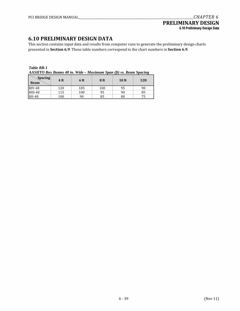
6.10 PRELIMINARY DESIGN DATA This section contains input data and results from computer runs to generate the preliminary design charts presented in Section 6.9. These table numbers correspond to the chart numbers in Section 6.9.
Table BB-1 AASHTO Box Beams 48 in. Wide – Maximum Span (ft) vs. Beam Spacing Spacing Beam
4 ft 6 ft 8 ft 10 ft 12ft
BIV-48 120 105 100 95 90 BIII-48 115 100 95 90 85 BII-48 100 90 85 80 75
PCI BRIDGE DESIGN MANUAL_______________________________________________________________________________CHAPTER 6 PRELIMINARY DESIGN
6.10 Preliminary Design Data
6 - 40 (Nov 11)
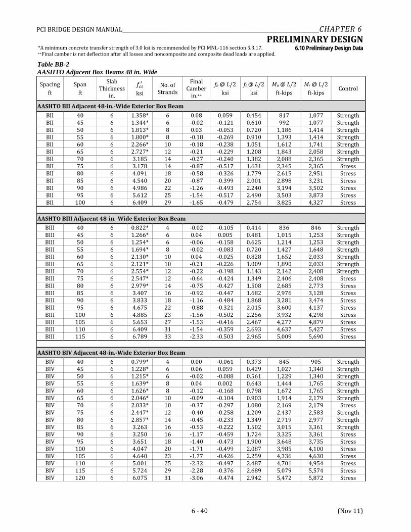
*A minimum concrete transfer strength of 3.0 ksi is recommended by PCI MNL-116 section 5.3.17. ++Final camber is net deflection after all losses and noncomposite and composite dead loads are applied. Table BB-2 AASHTO Adjacent Box Beams 48 in. Wide
Spacing ft
Span ft
Slab Thickness
in.
𝑓𝑐𝑖′ ksi
No. of Strands
Final Camber
in.++
fb @ L/2 ksi
ft @ L/2 ksi
Mu @ L/2 ft-kips
Mr @ L/2 ft-kips
Control
AASHTO BII Adjacent 48-in.-Wide Exterior Box Beam BII 40 6 1.358* 6 0.08 0.059 0.454 817 1,077 Strength BII 45 6 1.344* 6 -0.02 -0.121 0.610 992 1,077 Strength BII 50 6 1.813* 8 0.03 -0.053 0.720 1,186 1,414 Strength BII 55 6 1.800* 8 -0.18 -0.269 0.910 1,393 1,414 Strength BII 60 6 2.266* 10 -0.18 -0.238 1.051 1,612 1,741 Strength BII 65 6 2.727* 12 -0.21 -0.229 1.208 1,843 2,058 Strength BII 70 6 3.185 14 -0.27 -0.240 1.382 2,088 2,365 Strength BII 75 6 3.178 14 -0.87 -0.517 1.631 2,345 2,365 Stress BII 80 6 4.091 18 -0.58 -0.326 1.779 2,615 2,951 Stress BII 85 6 4.540 20 -0.87 -0.399 2.001 2,898 3,231 Stress BII 90 6 4.986 22 -1.26 -0.493 2.240 3,194 3,502 Stress BII 95 6 5.612 25 -1.54 -0.517 2.490 3,503 3,873 Stress BII 100 6 6.409 29 -1.65 -0.479 2.754 3,825 4,327 Stress
AASHTO BIII Adjacent 48-in.-Wide Exterior Box Beam
BIII 40 6 0.822* 4 -0.02 -0.105 0.414 836 846 Strength BIII 45 6 1.266* 6 0.04 0.005 0.481 1,015 1,253 Strength BIII 50 6 1.254* 6 -0.06 -0.158 0.625 1,214 1,253 Strength BIII 55 6 1.694* 8 -0.02 -0.083 0.720 1,427 1,648 Strength BIII 60 6 2.130* 10 0.04 -0.025 0.828 1,652 2,033 Strength BIII 65 6 2.121* 10 -0.21 -0.226 1.009 1,890 2,033 Strength BIII 70 6 2.554* 12 -0.22 -0.198 1.143 2,142 2,408 Strength BIII 75 6 2.547* 12 -0.64 -0.424 1.349 2,406 2,408 Stress BIII 80 6 2.979* 14 -0.75 -0.427 1.508 2,685 2,773 Stress BIII 85 6 3.407 16 -0.92 -0.447 1.682 2,976 3,128 Stress BIII 90 6 3.833 18 -1.16 -0.484 1.868 3,281 3,474 Stress BIII 95 6 4.675 22 -0.88 -0.321 2.015 3,600 4,137 Stress BIII 100 6 4.885 23 -1.56 -0.502 2.256 3,932 4,298 Stress BIII 105 6 5.653 27 -1.53 -0.416 2.467 4,277 4,879 Stress BIII 110 6 6.409 31 -1.54 -0.359 2.693 4,637 5,427 Stress BIII 115 6 6.789 33 -2.33 -0.503 2.965 5,009 5,690 Stress
AASHTO BIV Adjacent 48-in.-Wide Exterior Box Beam
BIV 40 6 0.799* 4 0.00 -0.061 0.373 845 905 Strength BIV 45 6 1.228* 6 0.06 0.059 0.429 1,027 1,340 Strength BIV 50 6 1.215* 6 -0.02 -0.088 0.561 1,229 1,340 Strength BIV 55 6 1.639* 8 0.04 0.002 0.643 1,444 1,765 Strength BIV 60 6 1.626* 8 -0.12 -0.168 0.798 1,672 1,765 Strength BIV 65 6 2.046* 10 -0.09 -0.104 0.903 1,914 2,179 Strength BIV 70 6 2.033* 10 -0.37 -0.297 1.080 2,169 2,179 Stress BIV 75 6 2.447* 12 -0.40 -0.258 1.209 2,437 2,583 Strength BIV 80 6 2.857* 14 -0.45 -0.233 1.349 2,719 2,977 Strength BIV 85 6 3.263 16 -0.53 -0.222 1.502 3,015 3,361 Strength BIV 90 6 3.250 16 -1.17 -0.459 1.724 3,325 3,361 Stress BIV 95 6 3.651 18 -1.40 -0.473 1.900 3,648 3,735 Stress BIV 100 6 4.047 20 -1.71 -0.499 2.087 3,985 4,100 Stress BIV 105 6 4.640 23 -1.77 -0.426 2.259 4,336 4,630 Stress BIV 110 6 5.001 25 -2.32 -0.497 2.487 4,701 4,954 Stress BIV 115 6 5.724 29 -2.28 -0.376 2.689 5,079 5,574 Stress BIV 120 6 6.075 31 -3.06 -0.474 2.942 5,472 5,872 Stress