michelin truck tire service manual (rubber manufacturers association) care and service of truck and...
TRANSCRIPT

Michelin® Truck TireService Manual
MICHELINQ U A L I T Y S T A T E M E N T
The Company exists because of our Customer: our true boss.
Our goals at all times are:
� To offer the Customer the best tire at the best pricein each segment of the market,
� To set the standard in Quality of service.
Each employee is expected to actively participate in ourprogress toward Total Quality by:
� Anticipating and satisfying Customers' expectations,
� Achieving Right the First Time in all activities,
� Continuously improving the Quality of products andservices.
September 1996
E. Michelin R. Zingraff

INTRODUCTIONRead this manual carefully - it is important for the SAFE operation and servicing of your tires.
The purpose of this manual is to provide you, the Michelin® Truck Tire customer, with some useful infor-mation to help you obtain maximized performance and cost per mile. Your Michelin radial tires are a signifi-cant investment and should be protected like any other investment. This manual will show you how to do thisby increasing your knowledge of tires regarding their selection, vehicle characteristics that affect performance,maintenance, and extending tire life through repair and retreading. For complete tire specifications, refer toapplication data books, contact your local Michelin Representative, or refer to the Michelin web site:www.michelintruck.com.
For additional information consult the following manuals:Michelin Data Book (Passenger Tire and Light Truck Tire) . . . . . . . . . . . . . . . . . . . . . . . . . . . . . . . . . . . . . . . . . . . . . MDL41780Michelin Truck Tire, Retreads and Commercial Light Truck Tire Data Book . . . . . . . . . . . . . . . . . . . . . . . . . . . . . MWL40731BFGoodrich Commercial Truck Tires Data Book . . . . . . . . . . . . . . . . . . . . . . . . . . . . . . . . . . . . . . . . . . . . . . . . . . . . . . BWL42029Tires for Material Handling . . . . . . . . . . . . . . . . . . . . . . . . . . . . . . . . . . . . . . . . . . . . . . . . . . . . . . . . . . . . . . . . . . . . . . . . . MEL41637Earthmover and Industrial Tire Reference . . . . . . . . . . . . . . . . . . . . . . . . . . . . . . . . . . . . . . . . . . . . . . . . . . . . . . . . . . . MEL41736Earthmover and Industrial Data Book . . . . . . . . . . . . . . . . . . . . . . . . . . . . . . . . . . . . . . . . . . . . . . . . . . . . . . . . . . . . . . . MEL40017Michelin Commercial Truck Tire Nail Hole Radial Tire Repair Manual . . . . . . . . . . . . . . . . . . . . . . . . . . . . . . . . . MWT40163Michelin MRT Tread Width Informational Guide . . . . . . . . . . . . . . . . . . . . . . . . . . . . . . . . . . . . . . . . . . . . . . . . . . . . . MYT41805Crown / Sidewall Repair Template . . . . . . . . . . . . . . . . . . . . . . . . . . . . . . . . . . . . . . . . . . . . . . . . . . . . . . . . . . . . . . . . . . MWT40192Truck Tire Limited Warranty and Driver’s Manual . . . . . . . . . . . . . . . . . . . . . . . . . . . . . . . . . . . . . . . . . . . . . . . . . . . . MWE40021BFGoodrich® Truck Tire Warranty . . . . . . . . . . . . . . . . . . . . . . . . . . . . . . . . . . . . . . . . . . . . . . . . . . . . . . . . . . . . . . . . . . . BMW40844Passenger and Light Truck - Michelin Complete Warranty . . . . . . . . . . . . . . . . . . . . . . . . . . . . . . . . . . . . . . . . . . . . MDW41156Recreational Vehicle Tire Guide . . . . . . . . . . . . . . . . . . . . . . . . . . . . . . . . . . . . . . . . . . . . . . . . . . . . . . . . . . . . . . . . . . . . . MDL40660Michelin Agricultural Tire Data Book . . . . . . . . . . . . . . . . . . . . . . . . . . . . . . . . . . . . . . . . . . . . . . . . . . . . . . . . . . . . . . . . MUT41305BFGoodrich Agricultural Tire Data Book . . . . . . . . . . . . . . . . . . . . . . . . . . . . . . . . . . . . . . . . . . . . . . . . . . . . . . . . . . . . . BUT21140
Technical Bulletins: www.michelintruck.com
CDs:MICHELIN SCRAP TIRE CODING CD . . . . . . . . . . . . . . . . . . . . . . . . . . . . . . . . . . . . . . . . . . . . . . . . . . . . . . . . . . . . . . . MWP42396PLNA TECHNICAL VIDEOS CD#1 . . . . . . . . . . . . . . . . . . . . . . . . . . . . . . . . . . . . . . . . . . . . . . . . . . . . . . . . . . . . . . . . . . . MWP42398
— Fundamentals of Tire Wear— Runflat - Full Term Pinch Shock Impact Damage— The Critical Factor - Truck Blow Out
PLNA TECHNICAL VIDEOS CD#2 . . . . . . . . . . . . . . . . . . . . . . . . . . . . . . . . . . . . . . . . . . . . . . . . . . . . . . . . . . . . . . . . . . . MWP42399— ATTACC PLUS Vehicle Measurement Training— Runout & Match Mounting; Scrap Tire Analysis— What Every RV Owner Should Know About Tires
PLNA TECHNICAL VIDEOS CD#3 . . . . . . . . . . . . . . . . . . . . . . . . . . . . . . . . . . . . . . . . . . . . . . . . . . . . . . . . . . . . . . . . . . . MWP42435— Proper New Tire Mounting— Troubleshooting Vibration
X ONE® TECHNICAL VIDEOS CD . . . . . . . . . . . . . . . . . . . . . . . . . . . . . . . . . . . . . . . . . . . . . . . . . . . . . . . . . . . . . . . . . . . MWP42397X ONE PRESENTATION . . . . . . . . . . . . . . . . . . . . . . . . . . . . . . . . . . . . . . . . . . . . . . . . . . . . . . . . . . . . . . . . . . . . . . . . . . . . MWV42737
To obtain copies of these manuals, CDs/DVDs and videos contact your Michelin Sales Representative or contactPromotional Fulfillment Center at 1-800-677-3322, Option #2 (Monday through Friday, 9 a.m. to 6 p.m. Eastern Time).

DVDs:ENGINEERING SUPPORT TECHNICAL VIDEOS 2004 . . . . . . . . . . . . . . . . . . . . . . . . . . . . . . . . . . . . . . . . . . . . . . . . . MWP42662
TECHNICAL VIDEOS - 2004.1 TECHNICAL VIDEOS - 2004.2— ATTACC PLUS — How Tires Are Made— Fundamentals of Tire Wear — The Critical Factor - Truck Version— Run Out and Match Mounting — X One® vs Duals Controllability— Scrap Tire Analysis — How to Handle a Blowout— What Every RV Owner Should Know About Tires — Mounting the X One— New Tire Mounting — X One Coast Downs— Troubleshooting Vibration Complaints — Laurens Proving Grounds
— Mounting Two New TiresX ONE TIRES VS. DUALS ON A DOLLY . . . . . . . . . . . . . . . . . . . . . . . . . . . . . . . . . . . . . . . . . . . . . . . . . . . . . . . . . . . . . . MWV42823
Videos:ATTACC PLUS VIDEO - VEHICLE MEASUREMENT TRAINING . . . . . . . . . . . . . . . . . . . . . . . . . . . . . . . . . . . . . . . .MWV41200CRITICAL FACTOR - SCHOOL BUS VIDEO . . . . . . . . . . . . . . . . . . . . . . . . . . . . . . . . . . . . . . . . . . . . . . . . . . . . . . . . . . .MWV42336CRITICAL FACTOR - TRUCK VIDEO . . . . . . . . . . . . . . . . . . . . . . . . . . . . . . . . . . . . . . . . . . . . . . . . . . . . . . . . . . . . . . . .MWV41415CRITICAL FACTOR LOOP FOR TRUCKSTOPS . . . . . . . . . . . . . . . . . . . . . . . . . . . . . . . . . . . . . . . . . . . . . . . . . . . . . . . .MWV41488EXPLORING THE EDGE - TRUCK VIDEO . . . . . . . . . . . . . . . . . . . . . . . . . . . . . . . . . . . . . . . . . . . . . . . . . . . . . . . . . . . .MWV41826FUNDAMENTALS OF TIRE WEAR VIDEO . . . . . . . . . . . . . . . . . . . . . . . . . . . . . . . . . . . . . . . . . . . . . . . . . . . . . . . . . . . .MWV41504MICHELIN KEEPS YOU ROLLING VIDEO . . . . . . . . . . . . . . . . . . . . . . . . . . . . . . . . . . . . . . . . . . . . . . . . . . . . . . . . . . . .MWV41414NO COMPROMISE VIDEO . . . . . . . . . . . . . . . . . . . . . . . . . . . . . . . . . . . . . . . . . . . . . . . . . . . . . . . . . . . . . . . . . . . . . . . . .MWV41417PRE-TRIP INSPECTION VIDEO . . . . . . . . . . . . . . . . . . . . . . . . . . . . . . . . . . . . . . . . . . . . . . . . . . . . . . . . . . . . . . . . . . . . .MWV41416PROPER NEW TIRE MOUNTING VIDEO . . . . . . . . . . . . . . . . . . . . . . . . . . . . . . . . . . . . . . . . . . . . . . . . . . . . . . . . . . . . . MWV42433RADIAL RUNOUT AND MATCH MOUNTING VIDEO . . . . . . . . . . . . . . . . . . . . . . . . . . . . . . . . . . . . . . . . . . . . . . . . . MWV41721RV VIDEO - “WHAT EVERY RV OWNER SHOULD KNOW” . . . . . . . . . . . . . . . . . . . . . . . . . . . . . . . . . . . . . . . . . . . . . MWV42019SCRAP TIRE ANALYSIS VIDEO . . . . . . . . . . . . . . . . . . . . . . . . . . . . . . . . . . . . . . . . . . . . . . . . . . . . . . . . . . . . . . . . . . . . . . MWV41925TIRE PRESSURE SAFETY INSPECTOR VIDEO . . . . . . . . . . . . . . . . . . . . . . . . . . . . . . . . . . . . . . . . . . . . . . . . . . . . . . . . MWV41418TROUBLESHOOTING VIBRATION VIDEO . . . . . . . . . . . . . . . . . . . . . . . . . . . . . . . . . . . . . . . . . . . . . . . . . . . . . . . . . . . MWV42434X ONE MOUNTING & DISMOUNTING VIDEO . . . . . . . . . . . . . . . . . . . . . . . . . . . . . . . . . . . . . . . . . . . . . . . . . . . . . . . MWV42085X ONE SINGLE TIRE CONCEPT (RAPID LOSS OF AIR) VIDEO . . . . . . . . . . . . . . . . . . . . . . . . . . . . . . . . . . . . . . . . . MWV42091
Industry Contacts and Publications:TIA (Tire Industry Association) - Formerly ITRA and TANA www.tireindustry.org.
Commercial Tire Service Manual OSHA (Occupational Safety and Health Administration) www.osha.gov
Safety Standard No. 29 CFR, Part 1910.177TRIB (Tire Retread Information Bureau) www.retread.orgRMA (Rubber Manufacturers Association) www.rma.org
Care and Service of Truck and Light Truck Tires Inspection Procedures for Potential Zipper Ruptures in Steel Cord Radial Medium and Light DutyTruck Tires (TISB 33, Number 2)
TMC (The Technology and Maintenance Council) www.truckline.comRecommended Engineering Practices ManualTMC RP 214B Tire/Wheel End Balance and RunoutTMC RP 216 Radial Tire Conditions Analysis GuideTMC RP 219 Radial Tire Conditions and Causes: A Guide to Wear Pattern Analysis TMC RP 222A Users Guide to Wheels and RimsTMC RP 642 Total Vehicle Alignment . . . . . . . . . . . . . . . . . . . . . . . . . . . . . . . . . . . . . . . . . . . . . . . . . . . . . . . . . . .MWL41875TMC RP 643 Air-Ride Suspension Maintenance Guidelines

TABLE OF CONTENTSSECTION ONE – TIRE SELECTION . . . . . . . . . . . . . . . . . . . . . . . . . . . . . . . . . . . . . . . . . . 1 - 12Why Radial? . . . . . . . . . . . . . . . . . . . . . . . . . . . . . . . . . . . . . . . . . . . . . . . . . . . . . . . . . . . . . . . . . . . . . . . . . . 1Why Michelin? . . . . . . . . . . . . . . . . . . . . . . . . . . . . . . . . . . . . . . . . . . . . . . . . . . . . . . . . . . . . . . . . . . . . . 2 - 3Which Michelin® Tire? . . . . . . . . . . . . . . . . . . . . . . . . . . . . . . . . . . . . . . . . . . . . . . . . . . . . . . . . . . . . . . 4 - 5Determining Michelin Tire Size. . . . . . . . . . . . . . . . . . . . . . . . . . . . . . . . . . . . . . . . . . . . . . . . . . . . . 6 - 10Truck Type by Weight Class . . . . . . . . . . . . . . . . . . . . . . . . . . . . . . . . . . . . . . . . . . . . . . . . . . . . . . 11 - 12
SECTION TWO – MOUNTING THE TIRE . . . . . . . . . . . . . . . . . . . . . . . . . . . . . . . . . . . 13 - 20General Instructions for Tubeless Tire Mounting/Demounting . . . . . . . . . . . . . . . . . . . . . . .13 - 14Mounting the Tire . . . . . . . . . . . . . . . . . . . . . . . . . . . . . . . . . . . . . . . . . . . . . . . . . . . . . . . . . . . . . . . 15 - 17Tubeless Tire Mounting/Demounting . . . . . . . . . . . . . . . . . . . . . . . . . . . . . . . . . . . . . . . . . . . . . 17 - 18Mounting the Assembly on the Vehicle . . . . . . . . . . . . . . . . . . . . . . . . . . . . . . . . . . . . . . . . . . . . 19 - 20
SECTION THREE – EXTENDING TIRE LIFE . . . . . . . . . . . . . . . . . . . . . . . . . . . . . . . 21 - 36Maintaining the Tire . . . . . . . . . . . . . . . . . . . . . . . . . . . . . . . . . . . . . . . . . . . . . . . . . . . . . . . . . . . . . 21 - 26Maintaining the Vehicle . . . . . . . . . . . . . . . . . . . . . . . . . . . . . . . . . . . . . . . . . . . . . . . . . . . . . . . . . . 27 - 34Quick Checks for Front Suspension Faults . . . . . . . . . . . . . . . . . . . . . . . . . . . . . . . . . . . . . . . . . . . . . 35Quick Checks for Rear Suspension Faults . . . . . . . . . . . . . . . . . . . . . . . . . . . . . . . . . . . . . . . . . . . . . . 36Quick Checks for Trailer System Faults . . . . . . . . . . . . . . . . . . . . . . . . . . . . . . . . . . . . . . . . . . . . . . . . . 36
SECTION FOUR – X ONE® . . . . . . . . . . . . . . . . . . . . . . . . . . . . . . . . . . . . . . . . . . . . . . . . . . 37 - 40
SECTION FIVE – REPAIRS . . . . . . . . . . . . . . . . . . . . . . . . . . . . . . . . . . . . . . . . . . . . . . . . . . 41 - 46Repairs . . . . . . . . . . . . . . . . . . . . . . . . . . . . . . . . . . . . . . . . . . . . . . . . . . . . . . . . . . . . . . . . . . . . . . . . . . . . .41Measuring Damages . . . . . . . . . . . . . . . . . . . . . . . . . . . . . . . . . . . . . . . . . . . . . . . . . . . . . . . . . . . . . . . . . 42Repair Limits . . . . . . . . . . . . . . . . . . . . . . . . . . . . . . . . . . . . . . . . . . . . . . . . . . . . . . . . . . . . . . . . . . . 42 - 43Puncture Repairs . . . . . . . . . . . . . . . . . . . . . . . . . . . . . . . . . . . . . . . . . . . . . . . . . . . . . . . . . . . . . . . . 44 - 46
SECTION SIX – RETREADING . . . . . . . . . . . . . . . . . . . . . . . . . . . . . . . . . . . . . . . . . . . . . . 47 - 49
SECTION SEVEN – COST ANALYSIS . . . . . . . . . . . . . . . . . . . . . . . . . . . . . . . . . . . . . . 50 - 51Cost Analysis . . . . . . . . . . . . . . . . . . . . . . . . . . . . . . . . . . . . . . . . . . . . . . . . . . . . . . . . . . . . . . . . . . . . . . . . 50Fuel Savings . . . . . . . . . . . . . . . . . . . . . . . . . . . . . . . . . . . . . . . . . . . . . . . . . . . . . . . . . . . . . . . . . . . . . . . . . 51
SECTION EIGHT – TUBE TYPE . . . . . . . . . . . . . . . . . . . . . . . . . . . . . . . . . . . . . . . . . . . . . . 52 - 56
SECTION NINE – APPENDIX . . . . . . . . . . . . . . . . . . . . . . . . . . . . . . . . . . . . . . . . . . . . . . . 57 - 74General Information . . . . . . . . . . . . . . . . . . . . . . . . . . . . . . . . . . . . . . . . . . . . . . . . . . . . . . . . . . . . . 57 - 59
Units of Measurement . . . . . . . . . . . . . . . . . . . . . . . . . . . . . . . . . . . . . . . . . . . . . . . . . . . . . . . . . . . . . 57Load Range/Ply Rating . . . . . . . . . . . . . . . . . . . . . . . . . . . . . . . . . . . . . . . . . . . . . . . . . . . . . . . . . . . . . 57Speed Symbol . . . . . . . . . . . . . . . . . . . . . . . . . . . . . . . . . . . . . . . . . . . . . . . . . . . . . . . . . . . . . . . . . . . . . 57Pressure Unit Conversion . . . . . . . . . . . . . . . . . . . . . . . . . . . . . . . . . . . . . . . . . . . . . . . . . . . . . . . . . . 57Approximate Weight of Materials . . . . . . . . . . . . . . . . . . . . . . . . . . . . . . . . . . . . . . . . . . . . . . . . . . . .58Load Index . . . . . . . . . . . . . . . . . . . . . . . . . . . . . . . . . . . . . . . . . . . . . . . . . . . . . . . . . . . . . . . . . . . . . . . . 59
Vehicle Alignment Field Method – ATTACC PLUS system . . . . . . . . . . . . . . . . . . . . . . . . . . . . 60 - 61Casing Management . . . . . . . . . . . . . . . . . . . . . . . . . . . . . . . . . . . . . . . . . . . . . . . . . . . . . . . . . . . . . 62 - 63Cold Climate Pressure Correction Data . . . . . . . . . . . . . . . . . . . . . . . . . . . . . . . . . . . . . . . . . . . . . . . . 64Conversion tables (standard – metric – degrees) . . . . . . . . . . . . . . . . . . . . . . . . . . . . . . . . . . . . . . . . 65Critical Six Fundamentals . . . . . . . . . . . . . . . . . . . . . . . . . . . . . . . . . . . . . . . . . . . . . . . . . . . . . . . . . . . . 65DOT Sidewall Markings . . . . . . . . . . . . . . . . . . . . . . . . . . . . . . . . . . . . . . . . . . . . . . . . . . . . . . . . . . . . . . 66Hub and Stud Piloted Wheel Types . . . . . . . . . . . . . . . . . . . . . . . . . . . . . . . . . . . . . . . . . . . . . . . . 67 - 68RPM Calculations . . . . . . . . . . . . . . . . . . . . . . . . . . . . . . . . . . . . . . . . . . . . . . . . . . . . . . . . . . . . . . . . . . . . 69Runout and Vibration Diagnosis . . . . . . . . . . . . . . . . . . . . . . . . . . . . . . . . . . . . . . . . . . . . . . . . . . .70 - 71Toe Measurement – Field Method . . . . . . . . . . . . . . . . . . . . . . . . . . . . . . . . . . . . . . . . . . . . . . . . . . . . .72Tire Damage – Effect and Cause / Scrap Inspection Form . . . . . . . . . . . . . . . . . . . . . . . . . . . . 73 - 74
INDEX . . . . . . . . . . . . . . . . . . . . . . . . . . . . . . . . . . . . . . . . . . . . . . . . . . . . . . . . . . . . . . . . . . . . . . . . . . . . 75
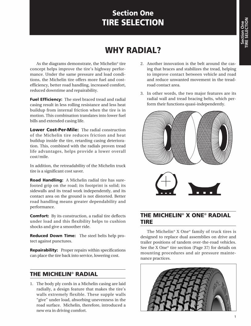
As the diagrams demonstrate, the Michelin® tireconcept helps improve the tire’s highway perfor-mance. Under the same pressure and load condi-tions, the Michelin tire offers more fuel and cost-efficiency, better road handling, increased comfort,reduced downtime and repairability.
Fuel Efficiency: The steel braced tread and radialcasing result in less rolling resistance and less heatbuildup from internal friction when the tire is inmotion. This combination translates into lower fuelbills and extended casing life.
Lower Cost-Per-Mile: The radial constructionof the Michelin tire reduces friction and heatbuildup inside the tire, retarding casing deteriora-tion. This, combined with the radials proven treadlife advantages, helps provide a lower overallcost/mile.
In addition, the retreadability of the Michelin trucktire is a significant cost saver.
Road Handling: A Michelin radial tire has sure-footed grip on the road; its footprint is solid; itssidewalls and its tread work independently, and itscontact area on the ground is not distorted. Betterroad handling means greater dependability andperformance.
Comfort: By its construction, a radial tire deflectsunder load and this flexibility helps to cushionshocks and give a smoother ride.
Reduced Down Time: The steel belts help pro-tect against punctures.
Repairability: Proper repairs within specificationscan place the tire back into service, lowering cost.
THE MICHELIN® RADIAL
1. The body ply cords in a Michelin casing are laidradially, a design feature that makes the tire’swalls extremely flexible. These supple walls“give” under load, absorbing unevenness in theroad surface. Michelin, therefore, introduced anew era in driving comfort.
2. Another innovation is the belt around the cas-ing that braces and stabilizes the tread, helpingto improve contact between vehicle and roadand reduce unwanted movement in the tread-road contact area.
3. In other words, the two major features are itsradial wall and tread bracing belts, which per-form their functions quasi-independently.
THE MICHELIN® X ONE® RADIALTIRE
The Michelin® X One® family of truck tires isdesigned to replace dual assemblies on drive andtrailer positions of tandem over-the-road vehicles.See the X One® tire section (Page 37) for details onmounting procedures and air pressure mainte-nance practices.
1
WHY RADIAL?
Section OneTIRE SELECTION
Sect
ion
On
eTI
RE
SELE
CTI
ON
Sect
ion
On
eTI
RE
SELE
CTI
ON

EXPERIENCE
Michelin. It’s a name known around the worldfor high quality tires and technological innovation.
Michelin has been earning that reputation formore than a century now, making radial tires foralmost every vehicle on the road — and in the air.
Michelin® tires are designed, produced andmarketed by a worldwide work force of over125,000 employees, with approximately 74 manu-facturing plants. In North America, Michelin oper-ates 21 plants in 17 locations and employs over23,920 people.
QUALITY
Before, during and after the manufacturingprocess, Michelin tires are processed and systemstested to ensure quality control. New methods oftesting are always being developed, to keep pro-ducing an outstanding product.
Engineers in physics, chemistry, electronics andother fields use a wide range of materials and tech-niques. Electron microscopy, x-rays, holography,transmission and absorption spectography, high-speed photography, infrared thermograph testingand various other investigative techniques are usedto study the tire and the tire-and-wheel-assemblyinteraction with the rest of the vehicle.
Quality control goes beyond the laboratory tothe production line itself. At each stage of the man-
ufacturing process, from raw materials to finishedproduct, production standards and requirementsare constantly verified.
Michelin’s North American facilities havegrown considerably since the first plants opened inthe early 1970s. Today, all plants incorporateMichelin’s latest technological developments andhighly automated production processes.
Testing plays an important role in assuringMichelin quality. That’s why Michelin operates theLaurens Proving Ground in South Carolina. Openedin 1976, the facility today includes a wide range oftesting capabilities for all categories of tires.
In addition, Michelin tires are fitted every dayon various vehicles and machines and testedrepeatedly on tracks, roads, highways and job sitesaround the world.
INTEGRITY
Because the tire is the vital contact between thedriver and the road, Michelin is dedicated to pro-viding customers with tires built for outstandingperformance and dependability at low cost-per-mile.
At Michelin, there is only one boss — the cus-tomer. It is the customer who judges the productand ultimately decides whether the company suc-ceeds or fails. So Michelin puts its considerabletechnological strength into a full line of radial tiresto meet customer needs.
2
Section
On
eTIR
E SELECTIO
N
WHY MICHELIN?EXPERIENCE, QUALITY, INTEGRITY —
NO COMPROMISE

3
MICHELIN’S MAJOR ACHIEVEMENTS
Sect
ion
On
eTI
RE
SELE
CTI
ON
1889 Brothers Edouard and Andre Michelinfounded the company as a small rubberfactory in Clermont-Ferrand, France.
1891 Michelin introduces the first pneumatic(air-filled) tire, which is easier to mountand repair.
1895 The first pneumatic car tire (from Michelin)helped make the automobile morepractical.
1906 Michelin develops the first removable rimand first spare tire which made repairssimpler.
1908 The first dual truck tires increase a vehicle’scarrying capacity, another Michelininnovation.
1908- Michelin produces tires in the United 1931 States at a Milltown, NJ plant, which was
closed in response to the Great Depression.
1923 Michelin invents the first low-pressurepassenger car tire to help enhance ridecomfort and traction.
1929 Michelin next turns to the rails, developingthe first rubber tire for railroad cars,helping to add comfort and reduce noise.
1938 Michelin replaces the usual textile fabric of atire with steel wire, the “Metallic,” whichwas the forerunner of the steel-belted radial.
1946 A revolution begins. Michelin patents thefirst steel-belted radial, giving driversdistinct advantages over bias-ply tires:longer mileage, better ride comfort, fewerflats, improved traction and greater fueleconomy.
1950 Michelin Tire Corporation, incorporated inNew York, begins selling tires in NorthAmerica.
1951 Michelin introduces the first radial plytruck tire.
1957 Michelin develops the radial tire forearthmovers.
1968 The Michelin® XWW tire becomes the firstoriginal equipment radial to be fitted onAmerican cars as Michelin radializes theU.S. market.
1970 Michelin opens its first North Americanmanufacturing plant in Canada.
1975 Michelin opens its first manufacturingplants in the United States.
1979 Michelin introduces the first low-profiletruck tire, which improves mileage, fueleconomy and handling.
1981 Michelin patents the first radial for jetairplanes to help provide significant weightsavings.
1987 The first radial for motorcycles is launchedby Michelin.
1991 New fuel savings technology is announcedfor passenger and truck tires.
1992 First full line of fuel-efficient “AdvancedTechnology” truck tires introduced for longhaul service.
1993 Michelin introduced the “Green” tire forautomobiles with its XSE® technology.
1995 Michelin introduces the world’s first 7-year / 700,000 mile / 3 retread casingwarranty
2000 Michelin introduces the X One® ProductLine.
2003 Michelin introduces the latest fuel savingsproducts: the XZA3™, XDA3™, and theEnergy tire line.
For over a century now, Michelin has been building a worldwide reputation for technological breakthroughafter breakthrough. The historical highlights presented here are some that have made the company what it istoday – and the modern tire what it is today.

4
WHICH MICHELIN® TIRE?Section
On
eTIR
E SELECTIO
N
The choice of tire type depends upon the appli-cation of the tire and wheel position. No matterwhat your application may be, Michelin has a tirespecifically designed for it. These applicationsinclude the following:
TRUCK TIRE APPLICATIONS
Long Haul (A)
The Long Haul application is composed of busi-nesses operating primarily in common carrier andlease rental vocations. Vehicle annual mileage –80,000 to 200,000.
Regional (E)
The Regional application is made up of busi-nesses such as public utilities, government – feder-al, state, and local, food distribution/process, man-ufacturing/process, petroleum, and schools oper-ating within a 300-mile radius. Vehicle annualmileage – 30,000 miles to 80,000 miles and a 300-mile or less operating radius.
On/Off Road (Y)
On/Off Road tires are designed to help providethe durability and performance necessary in highlyaggressive operating conditions at limited speeds.Vocations such as construction, mining and refuseuse these highly specialized tires. Vehicle annualmileage – 10,000 miles to 70,000.
XZA2® ENERGY XDA3™ XDN®2
XZA3™ XZA2® XZA®-1+
XD4® XT-1® X One® XTE™
X One® XDA-HT™ X One® XDA® X One® XTA®
XZE® XZE®2/XZE®2+ XDE® M/S
XDS® XDE®2+ X One® XDA-HT™
XZY®3 XZY-2™ XZY®
XTE™ XTE2® WIDE BASE X One® XTE™
XZY®3 WIDE BASE XZL™ WIDE BASE XDY-2™
XDY®3 XDE® A/T XDY-EX™

Urban (U)
Urban applications are very short mileage with ahigh percentage of stop and go. Primarily users arein retail/wholesale delivery and bus fleets. Vehicleannual mileage – 20,000 miles to 60,000 miles.
COMMERCIAL LIGHT TRUCK TIRE APPLICATIONS
• Highway Tires, All-Wheel-Position• All-Season, All-Terrain Tires• All-Terrain Drive Axle Traction Tires• Highway Mud & Snow Tires
INDUSTRIAL TIRE APPLICATIONS (MATERIAL HANDLING)
• Drive & Steer• Fork Lift/Utility Vehicles• Indoor/Outdoor Applications
SPECIAL TIRE APPLICATION
• Military• High Flotation• On and Off Road Applications
SMALL EARTHMOVER TIRES
• Mine, coal and quarry type applications (10.00R20, 11.00R20, 12.00R20 and 14.00R24/25)
Due to constant innovation and development,the types and sizes of Michelin® tires are alwayschanging. For the most current product offerings,please also refer to the product line brochures,the price lists, the applications data books andthe websites:
www.michelintruck.comwww.michelinearthmover.com
5
Sect
ion
On
eTI
RE
SELE
CTI
ON
LTX® A/S LTX® M/S LTX® A/T
XPS RIB® XPS TRACTION®
XZM™ X MINE® D2 XGLA2™
XR™ XK™ XKD1™
XF™ XZL™ X® LISSE COMPACTEUR™
XMP™ XS™XML™
XZM™ X-STRADDLE® X-TERMINAL T™
XZSL™
XZU®2 XZU®S X One® XZU®S

DEFINITIONS
1. Tire Size: Michelin® radial truck tire sizes aredesignated by the nominal section width ininches or millimeters and the rim diameter(e.g. 11R22.5 or 275/80R22.5). The “R” indi-cates a radial tire. Some sizes are also desig-nated with ISO (International StandardizationOrganization) markings for their load andspeed rating. (e.g., 144/141K, See AppendixSection).
2. Aspect Ratio: A nominal number, which rep-resents the section height, divided by the sec-tion width and expressed as a percentage.
Example 11R22.5 Aspect Ratio = 90
Example: Tire Size 275/80R22.5Aspect Ratio = 80
Example 445/50R22.5Aspect Ratio = 50
3. Rims: The approved/preferred rims are desig-nated for each size tire. Michelin tires shouldonly be mounted on the rims shown. The rimshown first is the preferred rim. Be sure tocheck rim manufacturers’ specifications.
4. Overall Width: The maximum width (crosssection) of the unloaded tires including pro-truding side ribs and decorations as measuredon the preferred rim. Overall width will change0.1 inch (2.5mm) for each 1⁄4 inch change inrim width.
5. Overall Diameter: The diameter of theunloaded new tire (measured from oppositeouter tread surfaces). Minimum dual spacingshould be adjusted accordingly.
6. Free Radius: One-half the overall diameter ofthe unloaded new tire.
7. Nominal Wheel Diameter: Diameter of rimseat supporting the tire bead given in nearestwhole numbers, e.g. 22.5".
8. Section Height: The distance from rim seatto outer tread surface of unloaded tire.
9. Loaded Radius: The distance from the wheelaxle centerline to the supporting surface undera tire properly inflated for its load according tothe load and inflation tables. (See Introductionfor listing of application specific data books.)
10. Tire Deflection: Free radius minus theloaded radius.
11. Revolutions Per Mile: Revolutions per milefor a tire size and tread is defined as the num-ber of revolutions that the new tire will make inone mile. Data is normally presented for theloaded tire at its rated load and inflation in thedrive position. Rolling circumference can becalculated from the revolutions per mile as fol-lows:
63,360 = Rolling circumference Revs per Mile in inches
A tire’s RPM can be determined by measuring,(using SAE J1025) or estimated by calculatingusing a mathematical equation. See SectionNine, Appendix (page 69) for RPM Calculations.
6
Section
On
eTIR
E SELECTIO
N
DETERMINING MICHELIN® TIRE SIZE
7. NominalWheel
Diameter
4. OverallWidth
8. SectionHeight
6. FreeRadius
3. RimWidth
5. OverallDiameter
9. LoadedRadius
10. Deflection
C L

All the information required to determine theproper tire size is contained in the application spe-cific data books. (See Introduction for listing.) Asample is shown below.
To select the proper tire size for a vehicle, it isnecessary to know the maximum axle loads that thetires will carry and the maximum continuous speedat which they will operate. The maximum load that
a tire can carry is different if it is mounted in dualconfiguration rather than single. The allowableaxle loads and the required inflation pressures tocarry these loads are shown in the charts for bothsingle and dual mountings in the current MichelinData Book — Truck Tires, Retreads and CommercialLight Truck Tires (MWL40731). The maximumallowable continuous speed is also indicated.
7
Sect
ion
On
eTI
RE
SELE
CTI
ON
Note: Rim listed first is the measuring rim.‡ Overall widths will change 0.1 inch (2.5 mm) for each 1/4 inch change in rim width. Minimum dual spacing should be adjusted accordingly.(1) Exceeding the lawful speed limit is neither recommended nor endorsed.Michelin® tires and tubes are subject to a continuous development program. Michelin North America, Inc. reserves the right to change product specifications at any time withoutnotice or obligations.
Specifications for Tread Design: XZA3™
275/80R22.5 XZA3 G 73146 18.6 473 40.1 1018 10.9 277 8.25, 12.3 312 518 19 75 6175 2800 110 5675 2575 110 760
7.50
Revs Max.Load Catalog Loaded Overall Overall Approved Min. Dual per Tread Speed Max. Tire Load Max. Tire Load
Size Tread Range Number Radius Diameter Width ‡ Rim Spacing ‡ Mile Depth (1) Single Dual kPa
in. mm. in. mm. in. mm. in. mm. 32nds mph lbs. kg. psi lbs. kg. psi
Load and Inflation Table for 275/80R22.5 LRG
PSI 70 75 80 85 90 95 100 105 110
kPa 480 520 550 590 620 660 690 720 760
lbs. S 9000 9450 9880 10310 10740 11020 11560 11960 12350
per axle D 16380 17200 18160 18760 19540 20280 21040 21760 22700
kg. S 4080 4280 4480 4680 4880 5000 5240 5420 5600
per axle D 7440 7800 8240 8520 8880 9200 9560 9880 10300
LOADS PER AXLE AND INFLATION PRESSURES
The carrying capacity of each tire size is tabulat-ed for various inflation pressures by individual tireload and by axle load for single applications (2 tires)and dual applications (4 tires). Due to the effects ofbouncing and crowned roads, the four tires in dualmay not equally share the axle load. Therefore, toprotect the tire carrying the largest share of the load,the capacity for duals is not twice the capacity for asingle formation, but is usually between 5 and 13%less depending on tire size. Insure that the air pres-sure between the dual tires and/or axles does notdiffer greater than 10 psi.
All trucks should be weighed, fully loaded, on ascale. Each axle, front and rear, must be weighed sepa-rately. Actual gross axle weights should be comparedwith the load and inflation tables to determine theinflation pressure required. The load carried by eachindividual front axle tire should be noted. Motorhomesshould be weighed by wheel end and determined byaxle weight by the highest load on the axle.
If the maximum load-carrying capacity of thetire is below the actual scale weight, greater carry-ing capacity tires should be used. This meanseither a tire with a higher load range or ply rating,or a larger tire size.
If the maximum load can be carried by the min-imum pressure, then a smaller size tire or a lowerply rated tire should be considered dependent onthe application and operation of the vehicle. Never reduce air pressure below minimum databook specification. Consult Michelin for specificsituations.
Ambient temperature will affect the air pres-sure within the tire. For every 10-degreetemperature change, pressure readings will changebetween 1 and 2 pounds. Consider this whenchecking pressures.
Additionally, altitude can have a slight effect onair pressure. For every 1,000 feet increase in alti-tude above sea level, air pressure will increaseapproximately 1/2 psi. For example, a tire inflatedto 100 psi at sea level will read slightly over 102 psiin Denver, Colorado.
Please consult with Michelin for additionalinformation on cold and hot climate corrections.
RIMS AND WHEELS
The correct rims and wheels for each tire size areindicated in the specification tables. For completetire specifications, refer to application specific databooks. (See Introduction for listing.)
MAXIMUM SPEED RESTRICTIONS*
Truck tires should normally be inflated accord-ing to the specification tables. The carrying capaci-ties and inflation pressures specified in these tablesare determined with the tire’s rated maximum speedin consideration. (See specifications tables for eachtire’s rated speed.) See current Michelin data book.
Reducing the maximum speed at which the tirewill operate and adjusting inflation pressuresaccording to the information contained in the fol-lowing chart can help increase the carrying capacity.To use the chart, multiply the load and pressurevalues taken from the specification section by theappropriate load and pressure coefficients given inthe chart. Note that the coefficients to be appliedare dependent on the tire’s rated maximum speedand on the speed at which the tire will be used.Give special attention to rim/wheel or vehicle axleratings that may be exceeded by the increased loadand pressure.
The following coefficients may be used by thevehicle manufacturer in determining the maximumgross axle weight rating (GAWR), bearing in mindrim or wheel and other component limitations. For existing vehicles or for speeds less than 20 mph(32 kph) please consult Michelin North America, Inc.
These limits apply only to Light Truck andTruck tires, but do not include Special Applicationtires, tires for high cube vans and low bed trailers.
* Exceeding the legal speed limit is neither recommended nor endorsed.
8
Section
On
eTIR
E SELECTIO
N
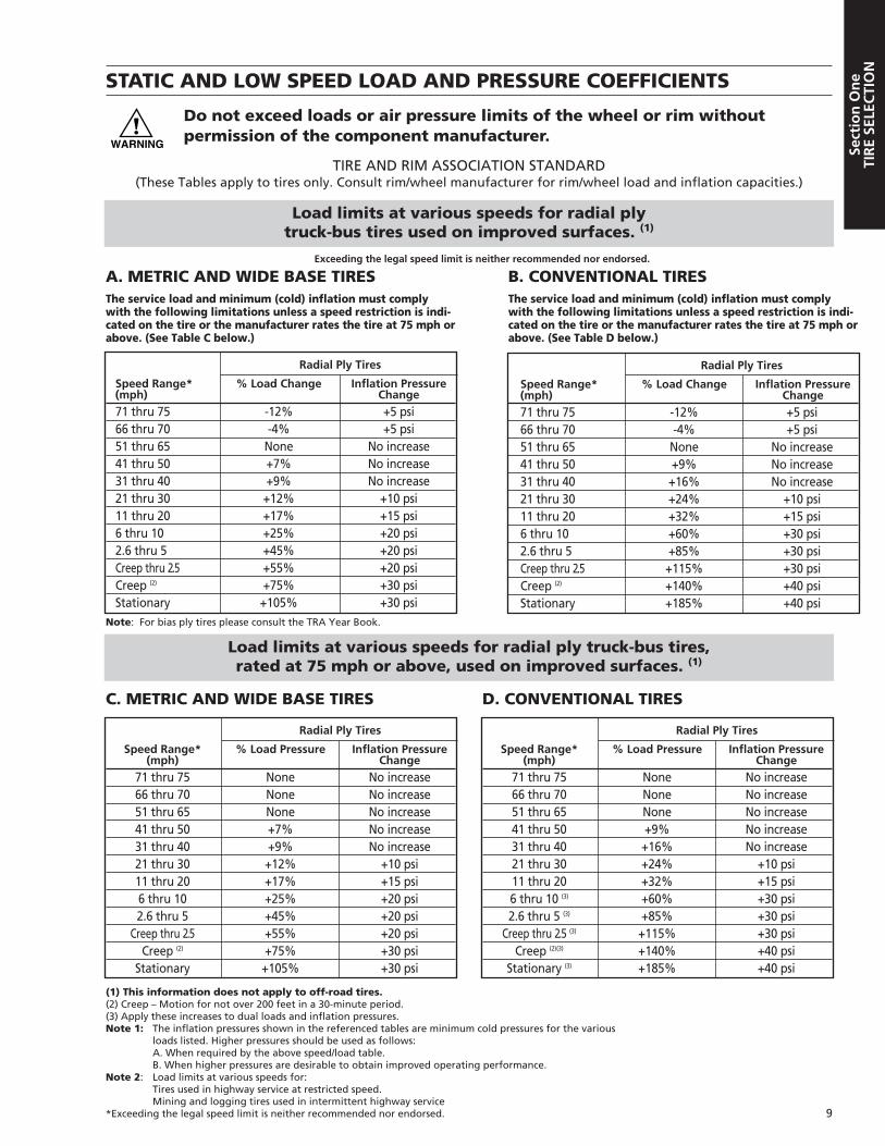
STATIC AND LOW SPEED LOAD AND PRESSURE COEFFICIENTS
Do not exceed loads or air pressure limits of the wheel or rim without permission of the component manufacturer.
9
Sect
ion
On
eTI
RE
SELE
CTI
ON
Load limits at various speeds for radial ply truck-bus tires used on improved surfaces. (1)
Load limits at various speeds for radial ply truck-bus tires, rated at 75 mph or above, used on improved surfaces. (1)
Radial Ply Tires
Speed Range* % Load Pressure Inflation Pressure(mph) Change
71 thru 75 None No increase66 thru 70 None No increase51 thru 65 None No increase41 thru 50 +7% No increase31 thru 40 +9% No increase21 thru 30 +12% +10 psi11 thru 20 +17% +15 psi6 thru 10 +25% +20 psi2.6 thru 5 +45% +20 psi
Creep thru 2.5 +55% +20 psiCreep (2) +75% +30 psi
Stationary +105% +30 psi
C. METRIC AND WIDE BASE TIRES
Radial Ply Tires
Speed Range* % Load Pressure Inflation Pressure(mph) Change
71 thru 75 None No increase66 thru 70 None No increase51 thru 65 None No increase41 thru 50 +9% No increase31 thru 40 +16% No increase21 thru 30 +24% +10 psi11 thru 20 +32% +15 psi6 thru 10 (3) +60% +30 psi2.6 thru 5 (3) +85% +30 psi
Creep thru 2.5 (3) +115% +30 psiCreep (2)(3) +140% +40 psi
Stationary (3) +185% +40 psi
D. CONVENTIONAL TIRES
TIRE AND RIM ASSOCIATION STANDARD(These Tables apply to tires only. Consult rim/wheel manufacturer for rim/wheel load and inflation capacities.)
(1) This information does not apply to off-road tires.(2) Creep – Motion for not over 200 feet in a 30-minute period.(3) Apply these increases to dual loads and inflation pressures.Note 1: The inflation pressures shown in the referenced tables are minimum cold pressures for the various
loads listed. Higher pressures should be used as follows:A. When required by the above speed/load table.B. When higher pressures are desirable to obtain improved operating performance.
Note 2: Load limits at various speeds for:Tires used in highway service at restricted speed.Mining and logging tires used in intermittent highway service
*Exceeding the legal speed limit is neither recommended nor endorsed.
Radial Ply Tires
Speed Range* % Load Change Inflation Pressure(mph) Change
71 thru 75 -12% +5 psi66 thru 70 -4% +5 psi51 thru 65 None No increase41 thru 50 +7% No increase31 thru 40 +9% No increase21 thru 30 +12% +10 psi11 thru 20 +17% +15 psi6 thru 10 +25% +20 psi2.6 thru 5 +45% +20 psiCreep thru 2.5 +55% +20 psiCreep (2) +75% +30 psiStationary +105% +30 psi
Radial Ply Tires
Speed Range* % Load Change Inflation Pressure(mph) Change
71 thru 75 -12% +5 psi66 thru 70 -4% +5 psi51 thru 65 None No increase41 thru 50 +9% No increase31 thru 40 +16% No increase21 thru 30 +24% +10 psi11 thru 20 +32% +15 psi6 thru 10 +60% +30 psi2.6 thru 5 +85% +30 psiCreep thru 2.5 +115% +30 psiCreep (2) +140% +40 psiStationary +185% +40 psi
A. METRIC AND WIDE BASE TIRESThe service load and minimum (cold) inflation must complywith the following limitations unless a speed restriction is indi-cated on the tire or the manufacturer rates the tire at 75 mph orabove. (See Table C below.)
B. CONVENTIONAL TIRESThe service load and minimum (cold) inflation must complywith the following limitations unless a speed restriction is indi-cated on the tire or the manufacturer rates the tire at 75 mph orabove. (See Table D below.)
Exceeding the legal speed limit is neither recommended nor endorsed.
Note: For bias ply tires please consult the TRA Year Book.

10
Section
On
eTIR
E SELECTIO
N
MICHELIN® TRUCK TIRE SIZEMARKINGS
Most truck tire sizes are indicated by the sectionwidth in inches, followed by R for radial, followed bythe rim or wheel diameter in inches:
TUBELESS 11R22.511 = nominal section in inchesR = radial22.5 = rim or wheel diameter in inches
MICHELIN® LOW-PROFILE TRUCKTIRES
The Low-Profile tire is marked in accordancewith the ISO (International StandardizationOrganization) system and contains load indices,which indicate the load capacity of the tire in singleand in dual usage.
Example: 275/80R24.5 LRG 144/141K 275 = nominal cross section in mm (metric)80 = aspect ratioR = radial24.5 = rim or wheel diameter in inchesLRG = load range G144 = load index in single mounting141 = load index in dual mountingK = speed code indicating maximum
speed of the tire
Michelin introduced the first low-profile radialtruck tire for long haul in 1979 to meet the needs ofAmerica’s transportation industry. The Michelin®
low-profile radial truck tire has established newstandards for America’s tires.
Compared to standard radial tires, the low-profiles offer:• Longer original tread mileage• Greater casing life• Lower weight for increased payloads• Lower height for greater clearance on trailers
and/or greater cargo space with a newly designed trailer
• Excellent traction, handling and stability.
EQUIVALENT LOW-PROFILE SIZES
MICHELIN T&RA REPLACES235/80R22.5 245/75R22.5 9R22.5255/80R22.5 265/75R22.5 10R22.5275/80R22.5 295/75R22.5 11R22.5275/80R24.5 285/75R24.5 11R24.5
EQUIVALENT X ONE® TIRE SIZES
Dual Size X One® Size11R22.5, 275/80R24.5 455/55R22.5275/80R22.5 445/50R22.5
REGROOVING
Only Michelin truck tires that are marked“REGROOVABLE” on the sidewall may beregrooved. After regrooving, you must have at least3 ⁄32" of under tread covering the top ply. If steel isexposed the tire must be scrapped or retreaded. Inaddition, some tread designs will have a regroovingdepth indicator as shown below. Do not regroovebelow the depth of the indicator.
It is the responsibility of the regroover to assurethat all Federal Regulationsare met. See U. S. Code ofFederal Regulations: Title49, Transportation; Parts569 and 393.75.
SIPING
There is no reason to ‘sipe’ new Michelin tires(this includes newly retread tires). Drive tires (M/S)are optimized to provide desirable traction in dry,wet, snow and icy conditions. “Siping” may be ben-eficial when tires become worn. “Siping” does notautomatically affect the warranty. Michelin’s war-ranty covers defects in workmanship and material.If a tire fails or is rendered unserviceable as a resultof ‘siping’ the tire is not warrantable.
1.6 mm
Depth Indicator
4.0 mm
1.6 mm = 2/32nds4.0 mm = 5/32nds

11
Sect
ion
On
eTI
RE
SELE
CTI
ON
CLASS 1 CLASS 2 CLASS 3 CLASS 4 CLASS 5
6,000 Ibs. 6,001 to 10,000 Ibs. 10,001 to 14,000 Ibs. 14,001 to 16,000 Ibs. 16,001 to 19,500 Ibs.
GVW and less GVW GVW GVW GVW
MILK/BREAD MILK/BREAD MILK/BREAD CONVENTIONAL VAN RACK
UTILITY VAN UTILITY VAN COMPACT VAN LARGE WALK-IN LARGE WALK-IN
PICK-UP PICK-UP WALK-IN BUCKET
COMPACT VAN COMPACT VAN TREE SPECIALIST
WALK-IN WALK-IN BOTTLED GAS
MULTI-PURPOSE MULTI-PURPOSE
CREW COMPARTMENT CREW COMPARTMENTPICK-UP PICK-UP
PANEL MINI
TRUCK TYPE BY WEIGHT CLASS

12
Section
On
eTIR
E SELECTIO
N
CLASS 6 CLASS 7 CLASS 8 TRAILER NOTES
19,501 to 26,000 Ibs. 26,001 to 33,000 Ibs. 33,001 Ibs. and over Weight: Not specified
GVW GVW
TOW HOME FUEL FUEL VAN
FURNITURE TRASH DUMP DOUBLES
STAKE FIRE ENGINE CEMENT LIQUID TANK
COE VAN SIGHTSEEING REEFER DRY BULK
SCHOOL TRANSIT TANDEM AXLE VAN LOGGER
SINGLE AXLE VAN INTERCITY PLATFORM
BOTTLER GCW TO 65,000 GCW TO 80,000 DROP FRAME
LOW PROFILE COE MEDIUM LOW PROFILE DUMPCONVENTIONAL TANDEM COE
HIGH PROFILE COE HEAVY CONVENTIONAL REEFER
HEAVY TANDEM DEEP DROPCONVENTIONAL
COE SLEEPER AUTO TRANSPORTER
GVW = GrossVehicle Weight.The total weight ofthe loaded vehicleincludes chassis,body and payload.
GCW = GrossCombinationWeight. Total weight ofloaded tractor-trailer combinationincludes tractor-trailer and pay-loads.
GAWR = GrossAxle Weight Rating.Maximum allow-able load weightfor a specific spin-dle, axle, wheel andrim combination.
Identical vehiclesmay appear in dif-ferent vehicleweight classes. Thisis because of a dif-ference in the com-ponents installedin each vehiclesuch as engines,transmissions, rearaxles and even tiresthat are not readilydiscernible in theexternal appear-ance of those par-ticular vehicles.
TRUCK TYPE BY WEIGHT CLASS

A tire cannot perform properly unless it is mount-ed on the correct size rim or wheel. The following aregeneral instructions for demounting and mountingMichelin® tubeless tires, including the X One®.
For detailed instructions on mounting and demount-ing truck tires on particular types of rims and wheels,refer to the instructions of the rim and wheel manu-facturer or the RMA wall charts.
13
Sect
ion
Tw
oM
OU
NTI
NG
TH
E TI
RE
Tire and rim servicing can be danger-ous and must be done only bytrained personnel using proper toolsand procedures. Failure to read andcomply with all procedures mayresult in serious injury or death toyou or others.
Re-inflation of any type of tire andrim assembly that has been operatedin a run-flat or underinflated condi-tion (80% or less of recommendedoperating pressure) can result in seri-ous injury or death. The tire may bedamaged on the inside and canexplode while you are adding air.The rim parts may be worn, damagedor dislodged and can explosively sep-arate. Refer to RMA Tire InformationService Bulletin on potential “zipperruptures” (TISB 33 number 2).
Use of starting fluid, ether, gasoline orany other flammable material to lubri-cate, seal or seat the beads of a tube-less tire can cause the tire to explodeor can cause the explosive separationof the tire/rim assembly resulting inserious injury or death. The use ofany flammable material during tireservicing is absolutely prohibited.
Any inflated tire mounted on a rimcontains explosive energy. The useof damaged, mismatched or improp-erly assembled tire/rim parts cancause the assembly to burst apartwith explosive force. If you arestruck by an exploding tire, rim partor the air blast, you can be seriouslyinjured or killed.
Re-assembly and inflation of mis-matched parts can result in seriousinjury or death. Just because partscome in together does not mean thatthey belong together. Check forproper matching of all rim partsbefore putting any parts together.
Mismatching tire and rim diametersis dangerous. A mismatched tire andrim assembly may explode and canresult in serious injury or death. Thiswarning applies to any combinationof mismatched components, such as14" and 14.5", 15" and 15.5", 16" and16.5", 17" and 17.5", 18", and 18.5"or 19" and 19.5" tires, and rim combi-nations. Never assemble a tire andrim unless you have positively identi-fied and correctly matched the parts.
WARNINGS!
GENERAL INSTRUCTIONS FOR TUBELESS TIRE MOUNTING/DEMOUNTING
Section TwoMOUNTING THE TIRE

14
Section
Two
MO
UN
TING
THE TIR
E
Directional Tires. When mounting any direc-tional tire, insure directional arrow points towardthe direction of travel during the original life.
1. SELECTION OF PROPER COMPONENTSAND MATERIALS:
a. All tires must be mounted on the properrim/wheel as indicated in the specificationstables. For complete tire specifications, refer toapplication specific data books. (SeeIntroduction for listing.)
b. Make certain that rim/wheel components areproperly matched and of the correct dimen-sions for the tire.
c. Always install new valve cores, and metal valvecaps containing plastic or rubber seals.
d. Always replace any rubber valve stem on a 16"through 19.5" wheel.
e. Always use a safety device such as an inflationcage or other restraining device that will con-strain all rim/wheel components during anexplosive separation of a multi-piece rim/wheel,or during the sudden release of the contained airof a single piece wheel that is in compliancewith OSHA standards. Never stand over a tire orin front of a tire when inflating. Always use aclip-on valve chuck with an in-line valve with apressure gauge or a presettable regulator and asufficient length of hose between the clip-onchuck and in-line valve (if one is used) to allowthe employee to stand outside the trajectorypath when inflating. Note: Safety cages,portable and/or permanent are also available forinflation of the X One® tire assemblies.
2. TIRE AND RIM LUBRICATION:
It is essential that an approved tire mountinglubricant be used. Preferred materials for use asbead lubricants are vegetable oil soaps or animalsoaps, in solution. Never use antifreeze, silicones,or petroleum-base lubricants. Improper ratios ofapproved lubricants and water may have a harmfuleffect on the tire and wheel.
The lubricant serves the following three purposes:• Helps minimize the possibility of damage to the
tire beads from the mounting tools. • Helps ease the insertion of the tire onto the rim
by lubricating all contacting surfaces.
• Assists proper bead seating (tire/rim centering)and helps to prevent eccentric mountings.Avoid using excessive amounts of lubricants.
CAUTION: It is important that tire lubricantbe clean and free of dirt, sand, metal shavings orother hard particles. The following practice is rec-ommended:
a. Use a fresh supply of tire lubricant each daydrawing from a clean supply and placing thelubricant in a clean portable container.
b. Provide a cover for the portable container and/orother means to prevent contamination of thelubricant when not in use. For lubricants insolution, we suggest the following methodwhich has proven to be successful in helping tominimize contamination and prevent excesslubricant from entering the tire casing: provide aspecial cover for the portable container that hasa funnel-like device attached. The small openingof the funnel should be sized so that when aswab is inserted through the opening into thereserve of lubricant and then withdrawn, theswab is compressed, removing excess lubricant.This allows the cover to be left in place provid-ing added protection. A mesh false bottom inthe container is a further protection against con-taminants. The tire should be mounted andinflated promptly before lubricant dries.
3. PREPARATION OF WHEELS, RIMS AND TIRES:
Never weld or apply heat to a rim or wheel onwhich a tire is mounted.
a. Always wear safety goggles or face shields whenbuffing or grinding rims or wheels.
b. Inspect wheel/rim assemblies for cracks, distor-tion, and deformation of flanges. Using a fileand/or emery cloth, smooth all burrs, welds,dents, etc. that are present on the tire side of therim. Inspect the condition of bolt holes on thewheels.
c. Remove rust with a wire brush and apply a rustinhibiting paint on steel wheels.
d. Remove any accumulation of rubber or grease,which might be stuck to the tire, being careful notto damage it. Wipe the beads down with a dry rag.

15
Sect
ion
Tw
oM
OU
NTI
NG
TH
E TI
RE
FITTING TIRES — NOT ORIGINALEQUIPMENT SIZES
When fitting tires of sizes different than thosespecified by the vehicle manufacturer, the follow-ing points must be considered:
1. GEAR RATIO:A change in tire dimension will result in a changein engine RPM at a set cruise speed, which willresult in a change in speed and fuel economy.The effect of tire size change on gear ratio shouldbe considered in individual operations:
• A decrease in tire radius will increase start-ability tractive torque and decrease gearedand indicated top speed.
• An increase in tire radius will reduce tractivetorque and increase top geared speed.
• RPM/SPEED/SIZE: These factors can effectRPM if corresponding changes are not made toengine ratios. Example: 11R24.5 XDA-HT (471rpm) versus 455/55R22.5 XDA-HT (494 rpm).471/494= .953, .953 X 60 mph = 57.21 mph
2. WHEEL DIAMETER:If a smaller wheel diameter is chosen, makesure that brake clearances are checked beforemaking a recommendation.
3. RIM WIDTH:An increase in the tire section may require awider rim with a greater offset.
4. OFFSET for dual wheels:The minimum offset required is determined bythe distance that must be left between the dualtires.
OFFSET for front wheels:Wider rims may require a different offset toavoid interference with vehicle parts.
5. TIRE CLEARANCES:
All clearances around a tire should be checked:• To the nearest fixed part of the vehicle, i.e., to
parts which are not affected by spring deflec-tion or steering mechanism.
• To the nearest part of the vehicle, which can bemoved, i.e., parts that are affected by springdeflection or steering mechanism.
Minimum clearances permissible:• To a fixed part 15 mm (5/8")• To a moveable part 25 mm (1")
a. Lateral ClearancesLateral clearance is the smallest distance lateral-ly between the tire and the nearest fixed point ofthe vehicle. An increase in the offset of the innerwheel plus half any increase in the tire sectionwill reduce lateral clearance.
Note: The X One® tire should be mounted sothat the tire sits outward similar to an outerdual tire. This will offer exceptional lateralclearance. However, use of offset wheels maychange Gross Axle Weight Rating (GAWR), con-sult vehicle manufacturer.
MOUNTING THE TIRE
D
Offset(Outer)
OUTSIDE INSIDE
Center Line Center Line
Offset(Inner)
D = Minimum Dual Spacing
Overall Width
Lateral Clearance
Road Spring

16
Section
Two
MO
UN
TING
THE TIR
E
b. Vertical Clearances
A certain vertical clearance exists between thetop of the tread and some part of the vehicleimmediately above it, usually a fender. This willvary as the springs operate. The vertical move-ments of the whole axle, in relation to the wholechassis, are normally limited by an axle stop.When measuring vertical clearance, also mea-sure the axle stop clearance; the difference is theremaining vertical clearance. When checkingvertical clearance, consideration must be givento the degree of tread wear and an allowance of1" must be made if the tread on the existing tireis between 2 ⁄ 32" to 4 ⁄32".
Vertical and body clearances are decreased byany increase in the free radius of the tire.
Check to be sure that the body clearance is notless than the vertical clearance. A fender boltmay be closer to the tire than the fender. Thisthen is the smallest distance and should berecorded. (This may be corrected by reversingthe bolt.)
c. Longitudinal Clearances
The semi-elliptic spring method of suspensionpermits the axle to move back longitudinally aswell as vertically when the spring deflects. As aguide, the maximum backward movement maybe taken as one third of the distance betweenthe shackle pin centers. The remaining longi-tudinal clearance must be noted.
Lateral Clearance
Road Spring
CORRECT PLACEMENT
X One
Road Spring
INCORRECT PLACEMENT
X One
Vertical Clearance (VC)
Vertical Clearance (VC)
Axle Stop(Must be smaller than VCor tire tread will touch beforeaxle stop closes up)
Body Clearance
75 mm. (3")
Fixed Pivot
SpringShackle
Swing Pivot
LongitudinalClearance
Fixed Pivot

17
Sect
ion
Tw
oM
OU
NTI
NG
TH
E TI
RE
d. Front Wheel Clearances
The clearances of both front wheels must bemeasured on both steering lock positions.
Clearances of front wheels must be checkedturning wheels from full left lock to full rightlock, since the minimum clearance might occurat some intermediate point.
6. OVERALL WIDTH:
When fitting larger tires, the overall width of thevehicle across the tires is increased by half of the
increase in the cross section of each outside tireand the increase in offset of each outside wheel.
7. SPARE WHEEL RACK:
Always check the spare wheel rack to see thatthe tire will fit.
8. LEGAL LIMITS:
Most states and provinces in North Americahave legal limits for vehicle carrying capacities,overall vehicle dimensions, and minimumground clearances. Each of these factors mustbe taken into consideration. Check with localjurisdictions.
TUBELESS TIRE MOUNTING/DEMOUNTING
Check Clearances Here and All Positions From Lock to Lock
Bottom View
Overall Width of Body
Overall Width
Measure Here
Not Here
Re-inflation of any type of tire/rimassembly that has been operated in arun-flat or underinflated condition(80% or less of recommended pres-sure) can result in serious injury ordeath. The tire may be damaged onthe inside and can explode while youare adding air. The rim parts may beworn, damaged or dislodged and canexplosively separate.
DEMOUNTING OF TUBELESS TIRES
1. Before loosening any nuts, deflate the tire by re-moving the valve core.
2. With the tire assembly lying flat, break the beadseat of both beads with a bead breaking tool. Do
not use hammers of any type. Striking awheel/rim assembly with a hammer of any typecan damage the tire or wheel and endanger theinstaller. Use a steel duck billed hammer only as awedge. Do not strike the head of a hammer withanother hard faced hammer – use a rim mallet.
3. Apply the lubricant to all surfaces of the beadarea of the tire.
4. Beginning at the valve, remove the tire usingtire irons designed for this purpose. Starting atthe valve will minimize chances of damagingthe bead. Make certain that the flange with thetapered ledge that has the shortest span to thedrop center is facing up. Always attempt tokeep the bead not being worked by the irons, inthe full depth of the drop center cavity.
18
Section
Two
MO
UN
TING
THE TIR
E
MOUNTING TUBELESS TIRES
1. Inspect the condition of the bolt holes on thewheels, look for signs of fatigue. Check flangesfor excessive wear by using the wheel manufac-tures flange wear indicator.
2. Replace valve core and inspect valve stem fordamage and wear. We recommend alwaysreplacing the valve stem and using a new valvestem grommet. Insure valve stem is installedusing the proper torque value. 80-125 in/lbs(7-11 ft/lbs) for standard aluminum wheels and35-55 in/lbs (3-5 ft/lbs) for standard tubelesssteel wheels.
3. When applying lubricant to the rim, lubricatethe entire rim surface from flange to flange.The tire should be mounted and inflated beforethe lubricant dries.
4. With the rim short side (narrow side) up, lay thetire over the rim at the valve side and work it onwith proper tubeless tire tools, making full useof the drop center well. The 19.5-inch shouldbe mounted from the short side. Care shouldbe taken to insure that any internal monitoringsystem is not damaged or dislodged during thisservice.
5. Do not use any kind of hammer. Bead damagemay occur leading to tire destruction.
6. The X One® tire is designed to replace dual tireson the drive and trailer positions of tandemover the road vehicles and the tires must bemounted on 22.5 x 14.00" size wheels. Positionthe tire and wheel assembly so the valve stem isfacing outward, away from the vehicle.
INFLATION OF TUBELESSTIRES
Re-inflation of any type of tire/rimassembly that has been operated in arun-flat or underinflated condition(80% or less of recommended pres-sure) can result in serious injury ordeath. The tire may be damaged onthe inside and can explode while youare adding air. The rim parts may beworn, damaged or dislodged and canexplosively separate.
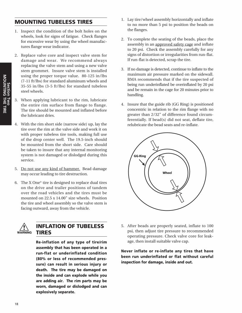
1. Lay tire/wheel assembly horizontally and inflateto no more than 5 psi to position the beads onthe flanges.
2. To complete the seating of the beads, place theassembly in an approved safety cage and inflateto 20 psi. Check the assembly carefully for anysigns of distortion or irregularities from run-flat.If run-flat is detected, scrap the tire.
3. If no damage is detected, continue to inflate to themaximum air pressure marked on the sidewall.RMA recommends that if the tire suspected ofbeing run underinflated be overinflated by 20 psiand be remain in the cage for 20 minutes prior tohandling.
4. Insure that the guide rib (GG Ring) is positionedconcentric in relation to the rim flange with nogreater than 2/32" of difference found circum-ferentially. If bead(s) did not seat, deflate tire,relubricate the bead seats and re-inflate.
5. After beads are properly seated, inflate to 100psi, then adjust tire pressure to recommendedoperating pressure. Check valve core for leak-age, then install suitable valve cap.
Never inflate or re-inflate any tires that havebeen run underinflated or flat without carefulinspection for damage, inside and out.
Wheel
GG-Ring

19
Sect
ion
Tw
oM
OU
NTI
NG
TH
E TI
RE
When wheel assemblies are mounted on a vehi-cle, be sure that the valves do not touch the brakedrums or any mechanical part of the vehicle. Whenmounting the X One® tire onto a vehicle, positionthe tire so that the tire sits on the outbound side ofthe wheel similar to where the outer dual wouldnormally be positioned. Also position the tire andwheel assembly so the valve stem is facing outward,away from the vehicle.
Valves of dual tires should be diametricallyopposite. Ensure that the inside valve is accessiblein order that the air pressure can be checked andthe tire inflated when necessary.
Tires mounted in duals must be matched sothat the maximum difference between the diame-ters of the tires does not exceed 1 ⁄ 4" (equates to4 ⁄32nds of tread depth) or a circumferential differ-ence of 3 ⁄4". Failure to properly match dual tireswill result in the tire with the larger diameter carry-ing a disproportionate share of the load.Mismatched duals can lead to rapid wear andexcessive fatigue.
IMPORTANT: Check to insure that you knowwhich mounting system you are working with andthat the components are correct. See Appendix,Section 9, Hub and Stud Piloted Wheel Types.(Reprinted with permission from RP 222A, User’sGuide to Wheels and Rims , published by theTechnology & Maintenance Council (TMC) of theAmerican Trucking Associations, 2200 Mill Road,Alexandria, VA 22314 (703) 838-1776 .)
DUAL SPACING
It is also important that sufficient space is pro-vided between dual tires to allow air to flow andcool the tires and to prevent the tires from rubbingagainst one another.
To make sure dual spacing is correct, simplymeasure the two tires from center to center of thetread, and refer to the minimum dual spacing col-umn in the application data books.
MEASURING TIRES IN DUALASSEMBLY
Measuring the circumferences of the tires withan endless tape after they are on the rims andinflated, but before they are applied to a vehicle, isthe most accurate method. The endless tape, as thename signifies, is a tape made of one half inchbending steel, one end of which passes through aslot at the other end of the tape and forms a loop.Measuring in this manner takes into account anyirregularities in wear.
In checking tires already on a vehicle, either (A)a square (similar to but larger than a carpenter’ssquare), (B) a string gauge, (C) a large pair ofcalipers, or (D) a wooden straight edge long enoughto lie across the treads ofall four tires, may beused.
Measuring with Endless Tape
A) Use of a Square
B) Use of String Gauge
MOUNTING THE ASSEMBLY ON THE VEHICLE

20
Section
Two
MO
UN
TING
THE TIR
E
MATCHING TIRES ON TANDEMAXLES
Tandem drive rear axles without an inter-axledifferential necessitate that the eight tires arematched so that the average tire circumference onthe one axle is within 3 ⁄ 4" of the average tire cir-cumference on the other axle.
Since any one tire of the size used with theseaxles may lose as much as 2 1 ⁄2" in circumferencedue to normal wear and still be serviceable, it isreadily seen that a wide difference in tire circum-ference may exist.
The best method of avoiding damage due tohaving tires of unequal circumferences is toinspect and match tires so that the average tirediameter on one axle is within 1 ⁄ 4" (equates to4/32nds of tread depth) of the average tire diame-ter on the other axle. Equal tire inflation at thepressures recommended by the tire manufacturershould be maintained.
TIRE MIXING
IMPROPER TIRE MIXING CAN BE DANGEROUS
Four Wheel Trucks: For the best perfor-mance it is recommended that the same size,design and construction of tire be used on all fourwheel positions. If only two Michelin® radials aremounted with two non-radials, the radials shouldbe mounted on the rear. If tires of different designare mixed on a vehicle in any configuration, theyshould not be used for long periods and speeds*should be kept to a minimum.
Mixing or matching of tires on 4-wheel drivevehicles may require special precautions. Alwayscheck vehicle manufacturers’ Owners Manual fortheir recommendations.
Trucks with more than four wheelpositions: For best performance, it is recom-mended that radial and non-radial tires should notbe mixed in dual fitment. It is unlawful and danger-ous to mix radials and bias tires on the same axle.
RUNOUT
When installing new tire/wheel assembly on thesteer axle, this is an ideal time to first verify theconcentricity of the guide rib area as well as insur-ing that both the radial and lateral runout measure-ments are the lowest possible to offer the driver thesmoothest ride. The variation in at least four mea-surements around the wheel should be no greaterthan 2⁄32nds of an inch. See Section Nine,Appendix, ‘Runout and Vibration Diagnosis’ forprocedures.
*Exceeding the legal speed limit is neither recommended or endorsed.
D) Use of a Wooden Straight EdgeC) Use of the Calipers

21
Sect
ion
Th
ree
EXTE
ND
ING
TIR
E LI
FE
INFLATION PRESSURE
The most critical factor in tire maintenance isproper inflation. No tire or tube is completelyimpervious to loss of air pressure. To avoid thehazards of underinflation, lost air must bereplaced.
Driving on any tire that does not have the cor-rect inflation pressure is dangerous and will causetire damage.
Any underinflated tire builds up excessive heatthat may result in sudden tire destruction. Thecorrect inflation pressures for your tires are a func-tion of many factors including: load, speed, roadsurface and handling.
Consult a Michelin ® Truck Tire dealer orMichelin data books for the proper inflation pres-sures for your application. See the Introductionfor complete listings of the Michelin data books.
Check inflation pressures on all your tires atleast once a week, including spares, before drivingwhen tires are cold, especially when vehicle is usedby more than one driver.
Failure to maintain correct inflation pressuremay result in sudden tire destruction, impropervehicle handling - possibly resulting in an accident- and may cause rapid and irregular tire wear.Therefore, inflation pressures should be checkedweekly and always before long distance trips.
Pressures should be checked when tires arecold; in other words, before they have been driven.The ideal time to check tire pressures is early morn-ing. Driving, even for a short distance, causes tiresto heat up and air pressures to increase.
Never bleed air from hot tires, as your tires willthen be underinflated. Make sure to check both tiresin a dual fitment. Pressures should be the same.Maximum allowable difference between tires in dualor between axles should be no greater than 10 psi.
Use an accurate calibrated tire gauge to checkpressures. (Do not use “Tire Billys” to hit tires as aninflation check. This is an unreliable method.)
For optimized tire performance, it is usuallybest to use the tire inflation pressure shown in theapplication data books for the particular axle load.Exceeding this pressure could result in reducedtraction and tread life.
However, for steering axle tires, it is oftenacceptable to use inflation pressures greater thanthat shown in the application data books for theparticular axle load. However, when operating thetire at maximum rated load never exceed the maxi-mum sidewall specified pressure by more than 10%unless technical approval is obtained fromMichelin North America, Inc. Never inflate to coldpressure beyond the rated capacity of the rim.
Following are two examples of applying the pre-vious considerations to an operation where theuser mounts new 275/80R22.5 XZA-1+ tires on asteer axle and desires to increase the air pressure inorder to see if this will help alleviate the occurrenceof irregular wear.
Example 1: If the axle load is 10,310 lbs., thenthe table in the data book specifies a correspondingpressure of 85 psi. So, the user can increase thepressure 15-20 psi above that to 100 or 105 psi.
Example 2: If the axle load is 12,350 lbs., thenthe table in the data book recommends 110 psi. Asthis is the maximum load of the tire, only a 10%pressure increase is permitted. Thus the adjustedpressure would be limited to 120 psi.
This procedure should not be applied “acrossthe board.” If you are getting satisfactory tire per-formance and wear with “table” pressures for agiven load, then leave well enough alone.
Overinflation can increase road shocks andvibrations transmitted to the vehicle.
Section ThreeEXTENDING THE TIRE LIFE
Once the tires have been put into operation, it is important that they and the vehicle are properly main-tained in order to obtain the maximized performance for which the tires have been designed.
MAINTAINING THE TIRE

CENTRAL TIRE INFLATION SYSTEM OR PRESSURE MONITORING SYSTEMS
Most of the systems on the market are capableof maintaining a cold inflation pressure in the tiresof 90 to 95 psi. Insure your system will maintain ahigh enough operating pressure in order for thetires to support the load at the desired speed. Tireson vehicles with these systems should still be visu-ally inspected before and after use.
RECREATIONAL VEHICLES
Michelin recommends weighing each wheelposition of the vehicle to determine the correctcold inflation pressure per tire for each wheel end.Refer to the Michelin Recreational Vehicle TireGuide (MDL40660) for specific recommendationsin inflation pressures and detailed proper proce-dures for weighing RVs. See Section Nine, of thispublication, Appendix for ‘Runout and VibrationDiagnosis’.
TIRE INSPECTION
While checking inflation pressures, it is a goodtime to inspect your tires. Anytime you see anydamage to your tires or wheels/rims, see anyMichelin Truck Tire dealer at once.
Before driving, inspect your tires, including thespare, and check your air pressures. If your pres-sure check indicates that one of your tires has lostpressure of 4 psi or more, look for signs of penetra-tions, valve leakage, or wheel/rim damage that mayaccount for air loss.
If the tire is 20% below the maintenance airpressure, it must be considered flat. Remove andinspect for punctures or other damage. If run-flatdamage is detected, scrap the tire. Refer to TMCRP 216 Radial Tire Conditions Analysis Guide.
Always examine your tires for bulges, cracks,cuts or penetrations. If any such damage isfound, the tire must be inspected by any MichelinTruck Tire dealer at once. Use of a damaged tirecould result in tire destruction, property damageand/or personal injury.
22
Section
Three
EXTEN
DIN
G TIR
E LIFE
Tread Contact Tread Contact Tread ContactWith Road With Road With Road
UNDERINFLATIONCauses abnormal tire deflection, which builds up heat and causes irregular wear.
OVERINFLATIONCauses tires to run hard and be more vulnerable to impacts.It also causes irregular wear.
PROPER INFLATIONThe correct profile for full contact with the road promotes traction, braking capability and safety.
Due to the unique casing design of the Michelin® X One®,traditional air pressure adjustment practices for dual tiresmay not apply to the X One product line. See Section 4 ofthis manual and applicable Technical Bulletins.
% OF RECOMMENDED INFLATION PRESSURE
EFFECTS OF INFLATION PRESSURE ON TIRE LIFE
MILEAGE OR TIRE
LIFE IN %
100
90
80
70
60
50
40
30
20
10
0 60 80 100 120
Loss of Service Dueto Underinflation
Loss of Service Dueto Overinflation
PROPERINFLATION
OVER-INFLATION
UNDER-INFLATION
NOTE: In no case should the maximum capacity ofthe wheel/rim be surpassed. Consult wheel/rimmanufacturer’s specifications.
NOTE: The following illustration is based on therecommended inflation pressure from the databook for the load being carried.

23
Sect
ion
Th
ree
EXTE
ND
ING
TIR
E LI
FE
DRIVE CAREFULLY
All tires will wear out faster when subjected tohigh speeds as well as hard cornering, rapid starts,sudden stops and frequent driving on surfaces thatare in poor condition. Surfaces with holes and rocksor other objects can damage tires and cause vehiclemisalignment. When you drive on such surfaces,drive on them carefully and slowly, and before dri-ving at normal or highway speeds, examine yourtires for any damage, such as cuts or penetrations.
TREAD DEPTH MEASUREMENTS
Tires should be measured for wear. This mea-surement can be taken in several spots across thetread and around the circumference. However, tocalculate the remaining amount of rubber (know-ing the new tire tread depth) for a given number ofmiles run, the measurement should always betaken at the same spot on the tread and close to thecenter groove of the tire, as shown below:
WEAR BARS
Michelin® truck tires contain "wear-bars" in thegrooves of the tire tread, which show up when only2⁄32nds of an inch or less of tread, is remaining.These are referenced on the shoulder by theMichelin Man™. Tread depths should not be takenon the wear bar indicators. At this stage your tiresmust be removed. Tires worn beyond this stage aredangerous. (Federal law requires truck tires on frontaxles to have at least 4⁄32nds of an inch tread depth.)
DO NOT OVERLOAD
The maximum load that can be put on a trucktire is dependent upon the speed at which the tirewill be used. Consult a Michelin Truck Tire dealeror the application data books for complete infor-mation on the allowable loads for your tires in yourapplication. Tires that are loaded beyond theirmaximum allowable loads for the particular appli-cation will build up excessive heat that may resultin sudden tire destruction, property damage andpersonal injury.
Some states have enacted "Load Per InchWidth" regulations for the purpose of governingaxle weight on (primarily) the steering axle of com-mercial vehicles. These regulations provide a car-rying capacity of a certain number of pounds pereach cross-sectional inch across the tire's width.The determination of the tire's width can vary fromstate to state, but presumably would be based uponeither the tire manufacturer's published technicaldata for overall width, or the width as marked onthe sidewall of the tire (which may require conver-sion from Metric to English units). It is recom-mended to contact your state’s DOT office to con-firm the current Load Per Inch Width Law.
For example, if a state allows for 550 pounds perinch width, a tire marked 11R22.5 could carry up to6,050 pounds (11 X 550) or a total of 12,100 poundson the steer axle (2 X 6,050). Another way to look atit is to take the total weight carried, and divide bythe stated Inch Width Law to determine the appro-priate size tire. If a commercial front end loader(sanitation vehicle) wants to carry 20,000 pounds ina state with a 600 pound per inch width limit(20,000 / 600 = 33.3), you would need a tire that is atleast 16.7 inches wide (33.3 / 2). In this case a425/65R22.5 could legally carry the load (425 / 25.4= 16.7 inches Metric to English conversion).
The two formulas are:– Load Per Inch Width Law x tire section width x
number of tires = gross axle weight limit.– Gross axle weight / Inch Width Law / number
of tires = minimum tire section width needed.
Do not exceed the gross axle weight ratings(GAWR) for any axle on your vehicle.

24
Section
Three
EXTEN
DIN
G TIR
E LIFE
DRIVE AT PROPER SPEEDS
The maximum continuous speed at whichMichelin truck tires can be operated is indicated inthe Michelin data books. See the Introduction forcomplete listings of the Michelin data books. Thisspeed varies for each type of tire and depends onthe type of application. Consult a Michelin TruckTire dealer (1-800-TIRE HELP) for assistance indetermining the maximum speed for your applica-tion. Exceeding this maximum speed will cause thetire to build up excessive heat that can result insudden tire destruction, property damage and per-sonal injury. In any case, you should not exceedreasonable speeds indicated by the legal limits anddriving conditions.
High speed driving can be dangerous and maybe damaging to your tires.
When driving at highway speeds, correct infla-tion pressure is especially important. However, atthese speeds, even with correct inflation pressures, aroad hazard, for example, is more difficult to avoid.
If contact is made, it has a greater chance of causingtire damage, than at a lower speed. Moreover, dri-ving at high speed decreases the time available toavoid accidents and bring your vehicle to a safe stop.
Do not exceed the maximum pressure capacityof the wheel. Consult the wheel manufacturer inthese cases.
BALANCE AND RUNOUT
It is customary to check tire balance if the drivermakes a ride complaint. Before removing the tire-wheel assembly from the vehicle, check for radial andlateral runout. Bent wheels and rims or impropermounting or flat spotting can cause excessive runout.If balance is still required, a simple static balancewith bubble balancer or a wall mounted axle bearingand hub type gravity balancer should be sufficient.
Current Technology Maintenance Council lim-its from RP 214B Tire/Wheel End Balance andRunout are listed below
TIRE / WHEEL ASSEMBLY BALANCE AND RUNOUT LIMITSTire Position 19.5 Over The Road On-Off Road Wide Base
Tires/Wheels Applications Applications Tires/Wheel
Maximum total weight correction expressed in ounces Steer 14 oz. 16 oz. 18 oz. 24 oz.of weight required to correct at rim diameter perrotating assembly Drive/Trailer 18 oz. 20 oz. 22 oz. 28 oz.
Lateral runout for rotating assemblySteer/Drive 0.095" 0.095" 0.110" 0.125"
Trailer 0.125" 0.125" 0.125" 0.125"
Radial runout for rotating assemblySteer/Drive 0.095" 0.095" 0.110" 0.125"
Trailer 0.125" 0.125" 0.125" 0.125"
NOTE: If tire and wheel assembly is within these limits and ride problem still exists, refer to TMC RP648 Diagnosing Ride Complaints.
RECOMMENDED BALANCE AND RUNOUT VALUES FOR DISC WHEELS AND DEMOUNTABLE RIMS
Balance Radial Runout Lateral Runout(See Note 2) (See Note 3) (See Note 3)
Tubeless Steel Disc Wheels 6 oz. max 0.07 inch max 0.07 inch max.
Tubeless Aluminum Disc Wheels 4 oz. max 0.03 inch max 0.03 inch max
Tubeless Demountable Rims N/A 0.07 inch max 0.07 inch max
Wide Base Wheels: Steel See Note 1 0.75 inch max 0.75 inch max
Aluminum See Note 1 0.30 inch max 0.30 inch max
NOTE 1: Refer to the manufacturer’s specifications for balance and runout values.NOTE 2: Amount of weight applied to rim to balance individual wheel component.NOTE 3: For steel wheels and demountable rims, the area adjacent to the rim butt weld is not considered in runout measurements.

25
Sect
ion
Th
ree
EXTE
ND
ING
TIR
E LI
FE
STORAGE
All tires should be stored in a cool dry placeindoors so that there is no danger of water collect-ing inside them. Serious problems can occur withtube-type tires when they are mounted with watertrapped between the tire and tube. Due to pressur-ization, the liquid can pass through the inner linerand into the casing plies. This can result in suddentire failure. Most of the problems of this naturehave been due to improper storage, which allowedwater to enter the casing. This is a particular prob-lem with tube-type tires because of the difficulty indetecting the water, which collected between thetire and tube. When tires are stored, they should bestored in a cool place away from sources of heatand ozone, such as hot pipes and electric motors.Be sure that surfaces on which tires are stored areclean and free from grease, gasoline or other sub-stances, which could deteriorate the rubber. Tiresexposed to or driven on these substances could besubject to sudden failure.
CHAINS
In order to satisfy legal requirements in manystates, you may need to require the use of chains ontruck tires. When the use of chains is required, thefollowing recommendations should be followed:
1. Chains should only be utilized when necessary.The possibility of damage to the tire or the chainincreases as driving speed and length of travel onthe chains increases, and is especially increasedby use on dry pavement. As a general rule,chains should be utilized only as long as required,and vehicle speeds should be kept relatively low.
2. Since manufacturers have size recommenda-tions for radial ply tires, no matter what type of“chain” they manufacture, these size recom-mendations must be adhered to for optimizedutility and performance.
3. Always be sure to check for proper clearancesbetween chain and vehicle.
4. Also follow closely the mounting instructionsand procedures of the chain manufacturer.
5. Specific chains are available for the X One® Xproduct line. Consult Michelin for propertype/size.
RECOMMENDATIONS FOR THEUSE OF DYNAMOMETERS
SEVERE DAMAGE can result in the crown areaof radial truck tires when run on dynamometers forextended periods. Quite often the damage is inter-nal and not discovered until after the vehicle hasbeen put back in service.
In order to avoid the possibility of damagingMichelin® radial truck tires, adhere to the followingtime/speed restrictions and related test parameters:This applies to tire sizes with bead seat diameters of19.5, 20, 22, 22.5, 24 and 24.5 inches.
NOTE: The times for the indicated speed in thechart are not additive.
• Allow a two-hour cool-down between tests.
• These limits are for an empty vehicle with tirepressures as indicated on the tire sidewall formaximum load.
MAXIMUM TIME (MINUTES)
On 8 5⁄8" On 18-20"
Speed (mph)* Dia. Rollers Dia. Rollers
62 (Max.) 2.5 4
50 3.5 6
40 5 8.5
30 7.5 14
20 16 35
10 42 105
*Exceeding the legal speed limit is neither recommended or endorsed.

• Allow a one-hour cool-down after each testbefore loading vehicle.
The maximum allowable center-to-center dis-tance between the two rollers in contact with a tireis a function of the sum of tire and roller diameter.This relationship is shown below:
Maximum Roller Spacing =Tire Diameter + Roller Diameter x 1.15
2
For example:
Note that in the above speed/time table a sig-nificant increase in time is allowed on the 18-20inch versus the 8 5⁄8-inch diameter roller. Forexample, at 30 mph time almost doubles from 7.5minutes to 14 minutes.
If these times and/or speeds areexceeded, irreversible internal dam-age in the tire could result, leadingultimately to tire destruction.
When it is anticipated that a test will exceedthese time/speed values, use “surrogate” tires (atire used in place of the normal tire).
SPINNING Major tire damage can occur in a short period
of time when a tire spins on a surface at highspeeds. When the speed difference between thewheel with good traction and the wheel withoutbecomes too great, the tire begins to disintegrate.This can occur on any slick surface (such as ice,mud and snow) or on a dry surface where there is avariance in traction. The resulting difference inspeed of the assembly can be as high as 4 times theregistered speed indicated, resulting in tire, and/ordifferential damage on the vehicle.
ROTATIONMichelin® radial tires should be rotated when
necessary. If the tires are wearing evenly, there isno need to rotate. If irregular wear becomes appar-ent or if the wear rate on the tires is perceptivelydifferent (from axle to axle for drive tires and side toside for steer tires), then the tires should be rotatedin such a manner as to alleviate the condition.
Rotation procedures such as those recommend-ed by vehicle manufacturers (see TMC RP 642 TotalVehicle Alignment) may be followed.
NOTE: There is no restriction on criss-cross rotation.
NOTE: Directional Tires. When mounting any direc-tional tire, insure directional arrow points toward thedirection of travel during the original tread life.
26
Section
Three
EXTEN
DIN
G TIR
E LIFE
MAX. ROLLER SPACING
Tire Size 85⁄8" Dia. 18" Dia.
275/80R22.5 28" 33.4"
255/70R22.5 26" 31.4"

27
Sect
ion
Th
ree
EXTE
ND
ING
TIR
E LI
FE
Many tire problems can be traced to mechani-cal conditions in the vehicle. Therefore, to obtainmaximized tire performance, vehicles must beproperly maintained.
MAJOR VEHICLE FACTORS WHICHAFFECT TIRE LIFE:
ALIGNMENT
Alignment refers not only to the various anglesof the steer axle geometry, but also to the trackingof all axles on a vehicle, including the trailer. Thedual purpose of proper alignment is to minimizetire wear and to maximize predictable vehicle han-dling and driver control. One of the challenges ofmeeting this goal is that alignments are typicallyperformed on a static, unloaded vehicle sitting on alevel floor. The vehicle then operates over varyingcontoured surfaces, under loaded conditions, withdynamic forces acting upon it. Predicting theamount of change between static/unloaded/level -versus – dynamic/loaded/contoured is difficultbecause many variables affect the amount ofchange. Variables such as Steering SystemCompliance (i.e., “play”) must be considered inmaking alignment setting recommendations.
We therefore recommend referring to TMC RP642 Total Vehicle Alignment, which has establishedindustry recommended target values for the align-ment of vehicles.
STEER AXLE GEOMETRY
Since very fewvehicles continue touse Center PointSteering, the follow-ing recommenda-tions are based onthe more commonInclined KingpinSteer Axle Geometry.
TOE
Toe is typically the most critical alignment con-dition affecting steer axle tire wear. The purpose ofsetting toe at a given specification is to allow thetire to run straight during normal operating condi-tions. Too much toe-in results in scrubbing fromthe outside inward on both tires and too much toe-out results in scrubbing from the inside outward onboth tires.
Total toe is the angle formed by two horizontallines through the planes of two wheels. Toe-in iswhen the horizontal lines intersect in front of thewheels, or the wheels are closer together in frontthan in back. Toe-out is when the horizontal linesintersect behind the wheels, or the wheels are closertogether in back than in front. Toe-in is commonlydesignated as positive, and toe-out as negative.
Steer axle toe is adjustable to reduce wear to theleading edge of the tire and also to avoid road wan-der. Toe is adjusted in a static, unloaded conditionso that the tires will run in a straight line under adynamic, loaded condition.
The toe measurement will probably change fromunloaded to loaded conditions. The amount ofchange will vary with axle manufacturer, axle rating,and steering arm geometry; but it is still fairly pre-dictable. Front axles on most popular Class 8 longhaul tractors will change in the direction of toe-outabout 1 ⁄ 32" (0.8 mm or .05 degree) for each 1000pounds of load increase on the steer axle. Cabovertractors with set-back-front-axles typically experi-ence less steer axle change in load from bobtail toloaded than do other configurations. Wheelbase andfifth wheel location are also major factors affectinghow much load change the steer axle will experience.
Inclined Kingpin
MAINTAINING THE VEHICLE
Toe-in

See Conversion Table at Section Nine,Appendix for conversion of fractions to millimetersto inches and degrees. See Section Nine, Appendixfor a Toe measurement field check method.
CAMBER
Camber is the angle formed by the inward oroutward tilt of the wheel referenced to a verticalline. Camber is positive when the wheel is tiltedoutward at the top, and negative when the wheel istilted inward at the top. Excessive positive cambermay cause smooth wear on the outer half of the tiretread. Excessive negative camber may cause wearon the inner half of the tread. Positive static-unloaded camber angles are built into the static-unloaded axle and put the loaded tire perpendicu-lar to the road. Steer axles with positive camberand steer axles with negative camber are bothavailable in the market. Studies have shown thatslightly negative camber in long haul applicationsreduces irregular tire wear and allows higherremoval mileage. Generally, the vehicle will pull tothe side with the most positive camber.
Camber correction by bending axles is NOTRECOMMENDED by Michelin. Consult the axlemanufacturer if camber is found to be incorrect(outside manufacturer specification).
CASTER
Positive (+) caster is the backward tilt at the topof the kingpin when viewed from the side.Negative (-) caster is the forward tilt of the top atthe kingpin when viewed from the side.
The purpose of caster is to provide self-aligningforces on the steer tires to stabilize the vehiclewhen driving straight down the road under brak-ing, free wheeling, and power conditions.
Insufficient caster reduces stability and cancause wander. Excessive caster increases steeringeffort and can cause shimmy. Either of these con-ditions may also have a detrimental effect on tirewear. Caster is adjustable with shims. Adjustingonly one side is not recommended. Caster on bothsides should be equal or not more than 1⁄2 degreedifference. Generally, the vehicle will pull to theside with the least positive caster.
STEER AXLE SETBACK (STEER AXLE SKEW)
Any measured deviation left (negative) or right(positive) away from perpendicular to the center-line of the vehicle is called the setback.
28
Section
Three
EXTEN
DIN
G TIR
E LIFE
Positive Camber Positive Caster + - Negative Caster0°
Top View

29
Sect
ion
Th
ree
EXTE
ND
ING
TIR
E LI
FE
TANDEM AXLE PARALLELISM
Tandem axle parallelism is critical because itcan have a detrimental effect on all ten tires on thetractor. Non-parallel drive axles tend to push thetractor into a turn in the direction that the axle endsare closest. In order for the vehicle to go straight,the driver must correct by steering in the oppositedirection. The vehicle can then go straight, but allten tires are at an angle to the direction of travel thatcauses scrubbing. Excessive tandem axle non-par-allelism is usually detected in steer tire wear. If onesteer tire is scrubbing from the outside inward andthe other steer tire is scrubbing from the inside out-ward, then tandem axle alignment is suspect.
THRUST ANGLE (TRACKING)
The relationship of the geometric centerline ofthe vehicle and the direction that the axle pointsgenerates a thrust angle. Ideally this relationshipwould result in a 0 degree value when the axle cen-terline is perpendicular to the geometric centerline. However, any deviation from this setting willincreasingly cause the vehicle to travel away fromthe straight line, causing the tires to “dog track”and scrub. Tracking to the right generates a posi-tive thrust angle; tracking to the left creates a nega-tive thrust angle.
TMC RECOMMENDED ALIGNMENT TARGETS
(Value representing industry-establishedmidpoint)
Steer Axle:Toe: +1 ⁄ 16" Toe-in
(0.08 degrees, 0.06 inches, 1.5 mm) Camber: Less than 1⁄ 4 degreeCaster: Left +3.5 degrees
Right +4.0 degreesSetback: 0 degrees / 0 inches
Drive, Trailer and Dolly Axles Thrust Angle (Square): 0 degrees / 0 inchesScrub (Parallelism): 0 degrees / 0 inchesLateral Offset: 0 degrees / 0 inches
TOE-OUT-ON-TURNS
(Turning Radius)
Toe-out-on-turns is the difference in the arcsdescribed by the steering tires in a turn. The pur-pose is to prevent the inside tire from scrubbingaround a turn since the outside tire (loaded tire)determines the turning radius of the steer axle.This is the Ackerman Principle. Improper geome-try results in wheel scrub in turns, which generallyappears as toe wear on the tire. More specifically,Ackerman wear shows itself as a rounded edgeradial feather wear across the tread area of the tire.This angle is more important on a city vehicle withits many turns than on a line haul unit.
Ackerman geometry is dependent upon thesteering axle track-width and wheel base of a vehi-cle. When the turning angle or wheel base changesfrom the original specification, Ackerman is affected.
Vehicle Pulls to Left
Top View
A
B
Top View
Steering Arms
Cross Bar(Tie Rod)
Rear Axle
Center of Rotation
Chas
sis
C L
C L
Basic Ackerman Steering Diagram
Wheel Base

PERIODIC ALIGNMENT CHECKS
An aggressive alignment preventative mainte-nance program should include the following peri-odic checks:
1. Upon delivery of new vehicles. Eventhough OEMs make a concerted effort to prop-erly align vehicles at the factory, shifting andsettling can occur during delivery. Camber andcaster may not change much, but Toe andTandem Axle Parallelism may change suffi-ciently to set up undesirable tire wear patternsif not corrected upon receipt.
2. At the first maintenance check. Postbreak-in alignment checks should be donebetween 15,000-30,000 miles but no later than90 days after the first in-service date. If shiftingand settling did not occur during delivery, it mayoccur during the first few thousand miles ofoperation. Many OEMs recommend retorquingsuspension/frame components after a few thou-sand miles of operation. A thorough alignmentcheck should be made during this inspection(after the retorquing). Consideration should begiven to different torque requirements on metricand standard bolts.
3. When new steer tires are installed orfront-end components are replaced.The steer tires coming out of service can tell astory of good or bad alignment. With this feed-back, an alignment program can continue toimprove. Without feedback, the best an align-ment program can do is stay at its current level.
4. When tire wear indicates a concern.“Reading” tire wear can help identify alignmentissues. Unfortunately, correcting the alignmentdoes not necessarily correct the tire wear pat-tern once an undesirable wear pattern has beenestablished.
ALIGNMENT EQUIPMENT
Alignment equipment exists that ranges fromsimple and inexpensive to sophisticated and costly.One factor that is common to all types of alignmentequipment is that the person using it is extremelyimportant to the resulting tire and vehicle perfor-mance! Calibration is another critical factor inmaintaining the accuracy of the system – followmanufacturers recommendations. Some fleetshave obtained excellent results with a good “scribeand trammel bar” and paying strict attention to
Toe and Axle Parallelism. Other fleets establishpermanent records, make adjustments more easily,have more information for trouble-shooting, andobtain excellent results with the more expensiveequipment. The common ground is that the per-son using the equipment understands it, uses itproperly, and follows the procedures consistently.
Michelin developed the Bib Alignment Systemto provide a highly portable system that combinessome of the best aspects of simplicity while stillproviding PC-based adjustment calculations and a“print out” permanent record. The Bib AlignmentSystem is an excellent tool for measuring andadjusting axle parallelism. It does not measurecaster, camber or toe.
Heavy truck alignment has evolved to a precisescience. The “field check” techniques may be usedto detect a problem condition, but are NOT recom-mended for making adjustments/corrections.Proper alignment equipment should be used if adecision is made to complete this service.
AXLE PARALLELISM AND TRACKING
In the straight-ahead position, the rear wheelsof a vehicle should follow the front wheels in a par-allel manner. Wheels that are out-of-track cancause excessive tire wear. Failure of the wheel totrack is usually due to the following causes:
a. Master spring-leaf brokenb. Worn springsc. Auxiliary leaves brokend. Loose “U” boltse. Incorrect or reverse springsf. Bent frameg. Locating rods or torque rods improperly
adjustedh. Locating rod or torque rod bushings worn
excessively
Failure of the wheels to track is usually quitevisible when one follows the vehicle on the high-way. It is possible that, due to one of the abovecauses, no uneven wear manifests itself on the reartires but an uneven wear pattern may show itselfon the front tires. This is because rear tires maypush the vehicle off course and give some toe-out-on-turns in the straight-ahead position to the fronttires. Hence, the driver makes a correction to offsetthe steering action caused by the rear wheels.
If the REAR axle of a vehicle is not at right anglesto the chassis centerline, the front tires are affected,
30
Section
Three
EXTEN
DIN
G TIR
E LIFE

31
showing misaligned wear. In the diagram below,the position of the rear axle of the vehicle has beenaltered because of a weakened left side spring – sothat the rear axle on the left side is further from thefront axle than the rear axle on the right side.
In this diagram, the rear axle causes its wheelsto point to the left side so that the rear end of thevehicle is, in fact, self-steered in that direction. Thevehicle would then steer itself to the right – unlessthe driver takes corrective action. If the driverwishes to travel straight ahead, he will naturallycompensate by turning his steering wheel. Thisaction of the driver introduces toe-out-on-turns asthough the vehicle were making a turn. The vehi-cle is not going around a turn; it is moving in astraight line – because the front wheels are toed-out. Misalignment wear patterns on the front tiresmay be apparent for this reason even though thefront wheel alignment settings may be correct.
How to Check Axle Parallelism andTracking:
With the vehicle fully loaded and relaxed on aflat surface, select two points on the front and rearaxles. These two points on each axle must be equaldistance from the chassis center (e.g., at the pointwhere the springs meet the axles). Using a plumbline, mark four points on the ground, move thevehicle away and measure the distance betweenthe marks as shown on the diagram.
If AD = BC and DE = CF, the axles are parallel. IfX = X’ and Y = Y’, the wheels are symmetrical ortracking. The Trailer Manufacturers Associationrecommends no more than 1 ⁄16 inch between axleends and 1 ⁄8 inch maximum from the trailer kingpin to the lead axle ends. If no other defect can befound, misalignment wear can only be attributed tosuch errors in parallelism or symmetry as may exist.
A more detailed field type procedure is recom-mended by Michelin and can be found in SectionNine, Appendix under Vehicle Alignment –ATTACC PLUS system on Page 60-61.
SpringsSprings
Vehicle Pulls to Right
Top View
Inside Wear
Outside Wear
Toe-out on turns at these steer angles is not equal to zero.
A
B
D
C
E
F
Y
X'
X
Y'
D
A
B
C
Y
Y'
X'
X
E
Schematic ofMeasurement Details
X = X'Y = Y'
AD = BCDE = CF
Schematic ofMeasurement Details
X = X'Y = Y'
AD = BC
Sect
ion
Th
ree
EXTE
ND
ING
TIR
E LI
FE
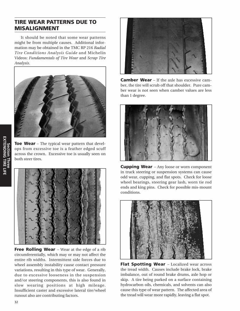
32
Section
Three
EXTEN
DIN
G TIR
E LIFE
TIRE WEAR PATTERNS DUE TOMISALIGNMENT
It should be noted that some wear patternsmight be from multiple causes. Additional infor-mation may be obtained in the TMC RP 216 RadialTire Conditions Analysis Guide and MichelinVideos: Fundamentals of Tire Wear and Scrap TireAnalysis.
Toe Wear – The typical wear pattern that devel-ops from excessive toe is a feather edged scuffacross the crown. Excessive toe is usually seen onboth steer tires.
Camber Wear – If the axle has excessive cam-ber, the tire will scrub off that shoulder. Pure cam-ber wear is not seen when camber values are lessthan 1 degree.
Flat Spotting Wear – Localized wear acrossthe tread width. Causes include brake lock, brakeimbalance, out of round brake drums, axle hop orskip. A tire being parked on a surface containinghydrocarbon oils, chemicals, and solvents can alsocause this type of wear pattern. The affected area ofthe tread will wear more rapidly, leaving a flat spot.
Free Rolling Wear – Wear at the edge of a ribcircumferentially, which may or may not affect theentire rib widths. Intermittent side forces due towheel assembly instability cause contact pressurevariations, resulting in this type of wear. Generally,due to excessive looseness in the suspensionand/or steering components, this is also found inslow wearing positions at high mileage.Insufficient caster and excessive lateral tire/wheelrunout also are contributing factors.
Cupping Wear – Any loose or worn componentin truck steering or suspension systems can causeodd wear, cupping, and flat spots. Check for loosewheel bearings, steering gear lash, worn tie rodends and king pins. Check for possible mis-mountconditions.

33
Sect
ion
Th
ree
EXTE
ND
ING
TIR
E LI
FEBraking Systems and Issues:
Air brake issues as they apply to tire wear anddamages can result from imbalance or componentconcerns.
Distorted, brittle and/or discolored rubber in thebead area are signs of the “outside to inside” break-down of rubber products as a result of seating on awheel surface which is heated to a temperaturebeyond the limit that the rubber products can toler-ate. This damage starts at a temperature in the mid-200 degree Fahrenheit range, with accelerated dam-age occurring above the 300 degree Fahrenheit range.
1. Brake imbalance can be the result of the air sys-tem, including valves, not actuating the brakessimultaneously. This may be the result of dirt,leaks and/or valve cracking pressure.
In a tractor/trailer combination, the more rapidbrake application time now being used (up totwice as fast as pre FMVSS-121 systems) canresult in a brake imbalance due to combina-tions of old tractors with new trailers or newtractors with old trailers.
2. Component situations, such as out-of-roundbrake drums or unevenly worn brake shoes, alsoresult in tires acquiring odd wear and flat spots.
3. Another source of brake imbalance is theimproperly adjusted slack adjuster. Any ofthese brake imbalance situations can result in
one or more wheel positions locking up and flatspotting the tires.
4. Brake drums with balance weights thrown mayresult in diagonal wear.
5. Brake lock (flat spots) conditions may be evidenceof deficiency in the Anti Lock Brake System.
Diagonal Wear – Localized wear diagonallyacross the tread width. Side forces imposed by acombination of toe and camber create diagonalstress in the footprint of the tire. Localized wearpatterns tend to follow this same direction creatingdiagonal wear. Causes include tandem in front ofaxle misalignment, excessive toe setting, axle mis-alignment, excessive steering system elasticity,incorrect steering angle in turns, and excessivecamber setting combined with high toe setting.
Lock Up
Brake Heat
SUMMARY OF TIRE ISSUES DUE TO BRAKES
Problem Possible Causes Result
Brake Heat
Lock Up
1. Overuse on downgrades due toimproper gear.
2. Brake dragging dueto mis-adjustment.
3. Repeated stopswithout coolingtime.
Bead damage tothe tire rangingfrom simpledistortion tocompleteunwrapping ofthe casing fromthe bead wire.
Flat spots andodd wear.
1. Out-of-roundbrake assembly.
2. Slow releasevalves.
3. Mis-adjustmentslack adjusters.

5th Wheel Maintenance and Placement:
Placement of the 5th wheel can be determinedby the need to properly distribute the load over thedrive tandems and the steer axle for legal loads. It can also be placed to lengthen or shorten the over-all length of the tractor-trailer unit. However, withsliding 5th wheels, many drivers place the 5th wheelto give the smoothest ride and easiest steering. Theplacement and movement of the 5th wheel canchange the tire loading substantially, causing tireoverload or tire underload conditions. Insufficientlubrication of the 5th wheel is a major cause ofpoor vehicle handling.
A 5th wheel in the most rearward position,combined with stiff front axle springs can cause thefront tire to periodically unload, leading to vehicleshimmy and irregular tire wear. Vehicle manufac-turers usually recommend a fifth wheel placementthat results in payload transfer to the front axle.Improper front axle load distribution can adverselyaffect braking and handling, which can result inexcessive tire wear.
Suspensions:
Forming the link between the truck and the tire,the suspension system provides a very importantcontribution to tire performance. The suspensionmust support the load and maintain the tire in the
proper operating position on the road. If the sus-pension is in good operating order, the tires willtrack straight and be evenly loaded. This promotesslow, even wear and low tire cost-per-mile.
Different truck manufacturers use different sus-pension systems. Some of these are adjustable formaking minor changes, and some are notadjustable. All suspensions have parts that moveand are, therefore, subject to wear. Worn or brokensuspension parts are one of the main causes ofirregular tire wear and handling concerns. (Ref. –Quick Checks for Suspension and System Faults onnext page.) When observing irregular wear on a tire,first check for worn or broken front and rear sus-pension parts.
As suspensions move away from multiplesprings, there is an increased need to dampen theeffect of road shock, increasing the need for func-tional shock absorbers and their related bushingsand parts. Shocks should be properly mounted toinsure proper dampening is achieved. Refer toTMC RP 643 Air-Ride Suspension MaintenanceGuidelines on air suspension systems.Replacement guidelines are indicated as 150,000 ina highway vocation and 100,000 in a regional voca-tion. Additionally, worn bushings result in move-ment when in a dynamic state and can lead toirregular tire wear.
34
Section
Three
EXTEN
DIN
G TIR
E LIFE

35
Sect
ion
Th
ree
EXTE
ND
ING
TIR
E LI
FE
SYMPTOM POSSIBLE CAUSE
Thumps and Knocks from Front Suspension • Loose or worn ball joints• Loose front suspension attaching bolts• Missing adjusting shims• Loose shock absorber mountings• Check spring eye bushings
Groans or Creaks from Front Suspension • Loose attaching bolts• Bent control arm or steering knuckle• Worn kingpins or kingpin bushings
Squeaks from Front Suspension • Coil spring rubbing on seat
Wander or Shimmy • Worn tie rod ends• Worn kingpins or kingpin bushings• Loose suspension attaching bolts• Weak shock absorbers• Weak front springs• Incorrect front end alignment
Frequent Bottoming of Suspension on Bumps • Weak front springs• Weak shock absorbers
Front End Sag • Weak front springs
Irregular or Excessive Tire Wear • Incorrect front wheel alignment• Worn kingpins or kingpin bushings• Loose front suspension attaching bolts• Weak shock absorbers• Weak front springs• Bent control arm or steering knuckle• Worn tie rod ends• Excessive steering system compliance
Floating, Wallowing and Poor Recovery from Bumps • Weak shock absorbers• Weak front springs
Pulling to One Side While Braking • Worn kingpins or kingpin bushings• Loose suspension attaching bolts• Bent control arm or steering knuckle• Weak front springs• Weak shock absorbers
Rough Ride and Excessive Road Shock • Damaged shock absorbers• Weak shock absorbers• Weak springs• Control arm shaft bushings need lubrication• Worn kingpins or kingpin bushings
Excessive Steering Play • Worn kingpins or kingpin bushings• Loose suspension attaching bolts• Worn control arm shaft bushings• Weak front springs• Worn tie rod ends
Pulls To One Side • Worn kingpins or kingpin bushings• Loose suspension attaching bolts• Worn control arm shaft bushings• Weak front springs• Incorrect wheel alignment• Bent control arm or steering knuckle
Hard Steering • Worn kingpins or kingpin bushings• Incorrect front end alignment• Bent control arm or steering knuckle
QUICK CHECKS FOR FRONT SUSPENSION FAULTS

36
Section
Three
EXTEN
DIN
G TIR
E LIFE
SYMPTOM POSSIBLE CAUSE
Shock Absorbers • Improperly installed mounts and/or bushings• Damaged or leaking shocks
U-Bolts • Not torqued to specification• Improperly torqued due to mismatched metric
and standard bolts with different specifications
Suspension System • Loose attaching bolts• Worn bushings in shocks, spring hangers,
torque rods• Missing alignment adjusting shims• Excessive drive axle offset • Excessive sway bar movement• Worn hanger pins allowing axle movement• Improperly functioning ride height control system
Wheels out of track (dog tracking) • Master or auxiliary spring-leaf broken• Incorrectly installed springs• Worn springs• Loose "U" bolts• Bent frame• Torque rods improperly adjusted • Torque rod bushings worn excessively
Alignment • Incorrect parallelism, skew, scrub• Dual position toe-in or out• Camber
Miscellaneous • Wheel bearings loose or damaged• 5th wheel placement• 5th wheel and chassis lubrication
QUICK CHECKS FOR REAR SUSPENSION FAULTS
QUICK CHECKS FOR TRAILER SYSTEM FAULTSSYMPTOM POSSIBLE CAUSE
Quick checks for trailer system faults would include: • Slider assembly movement, loose attaching bolts• Air-ride suspension movement • Insufficient lubrication• Worn shocks or springs• Alignment (toe, camber, parallelism)• Worn or loose wheel bearings• Brake imbalance• Slow release of trailer brake systems • Operational conditions, high scrub application• Tire scrub/dragging at dock deliveries• Air pressure maintenance (improper for operation)• Overloaded/underinflated, high speed empty hauls• Mismatched pressure by dual position or axle• Mismatched tread depth/tire design by dual position• Improper tread depth for application/operation• New steer tire(s) mixed in trailer positions• Tire rotated from steer or drive with existing wear• Improper tire assembly mounting• Driving habits, improper use of trailer brakes

37
Sect
ion
Fo
ur
X O
NE®
X ONE® AIR PRESSURE MAINTENANCE PRACTICES
Tire pressure maintenance advice for users ofthe new Michelin® X One® wide single truck tires(445/50R22.5 LRL and 455/55R22.5 LRL)
The Michelin® X One® family of truck tires isdesigned to replace dual assemblies on drive andtrailer positions in over-the-road applications.Proper air pressure maintenance is critical toobtain optimized performance from these tires.Due to the unique casing design of the Michelin X One tire, traditional air pressure adjustmentpractices for dual tires may not apply to Michelin X One tires. In order to ensure optimized perfor-mance of these tires, Michelin North America offersthe following guidelines:
1) Cold inflation pressure should be based on max-imum axle load in daily operation. Cold inflationpressures must not be lower than indicated inthe tables below for actual axle loads. For addi-tional information please consult the MichelinData Book — Truck Tires, Retreads, andCommercial Light Truck Tires (MWL40731).
2) If rapid or irregular wear develops, please referto the chart below for diagnostic steps:
A 10 psi incremental change in tire inflation willalleviate most wear forms derived from vehicleanomalies, driver influence and/or application.Always refer to actual axle loads to determinethe initial recommended cold inflation pressure.
Cold inflation pressures must not be lower thanindicated in the tables above for actual axle loads.
For example, the 445/50R22.5 X One® XDA®
tire, load Range L (20 ply) tires have a maximum airpressure of 120 psi (cold) with a weight carryingcapacity of 20,400 lbs. per axle. If the tire is mount-ed on a vehicle carrying 17,640 lbs. per axle, theappropriate air pressure is 100 psi (cold). Refer tothe Michelin Tire Data Book and TechnicalBulletins for appropriate recommendations. (SeeIntroduction for list of data books.)
For trailers equipped with an air pressure moni-toring system, system pressure should be regulatedbased on the maximum load the axle will carry andbe at the cold equivalent for this load.
In equivalent sizes there will be no requiredchange in gear ratios nor any required componentchanges. Consult your equipment manufacturerfor details. Contact Michelin directly for any varia-tion in specification.
EQUIVALENT X One® SIZESDual Size X One® Size
11R22.5 or 275/80R24.5 455/55R22.5275/80R22.5 445/50R22.5
445/50R22.5 LRLLOAD PER AXLE MAX LOAD PER TIRE*
psi 70 75 80 85 90 95 100 105 110 115 120 125 psi 120kPa 480 520 550 590 620 660 690 720 760 790 830 860 kPa 830
lbs.S 13260 14000 14740 15480 16200 16920 17640 18340 19020 19720 20400
lbs.S 10200
D D
kg.S 5960 6360 6660 7040 7320 7700 7980 8260 8620 8900 9250
kg.S 4625
D D
455/55R22.5 LRLLOAD PER AXLE MAX LOAD PER TIRE*
psi 75 80 85 90 95 100 105 110 115 120 125 130 psi 125kPa 520 550 590 620 660 690 720 760 790 830 860 900 kPa 860
lbs.S 14620 15400 16160 16920 17660 18400 19140 19860 20600 21200 22000
lbs.S 11000
D D
kg.S 6680 7000 7400 7700 8100 8380 8680 9060 9340 9720 10000
kg.S 5000
D D
Application Location Possible Causeon the Tire
Trailer TiresShoulder Pressure too low
Center Pressure too high
Drive TiresShoulder Pressure too high
Center Pressure too low
Section FourEXTENDING THE TIRE LIFE

WHEELS:
The X One® tires require the use of 22.5 X 14.00"wheels. The majority of the wheels currentlyoffered have a 2" outset, or offset. Outset is the dis-tance from the mounting surface of the wheel tothe centerline of the rim, when the rim centerline ismounted outboard of the hub face. Thus a wheelwith a 2" outset has the centerline of the rim base2" outboard from the hub mounting surface.
Some axle and hub manufacturers have recent-ly clarified and confirmed their position concern-ing the use of such wheels with their respectivecomponents. While the position of the componentmanufacturers is not totally consistent, the majori-ty’s view concerning the retrofit of duals with X Onetires can be summarized as follows:
* Many other axle and spindle combinations exist. Contact axle manufacturer.
Truck and trailer manufacturers may have dif-ferent specifications. For optimum track width, sta-bility and payload, end-users should talk to theirtrailer suppliers about the use of 83.5" axles withzero outset wheels. New wheel bearing productsmay be available at OEM and replacement, checkwith appropriate manufacturer.
VEHICLE TRACK:
With a standard length axle and 2 inch outsetwheels, the resulting variation in track width is anincrease of approximately 1.5 inch per side (3 inch-es total) as compared to a dual tire configuration.
End-users that have retrofitted vehicles with 2"outset wheels should contact their respectivevehicle, axle or component manufacturers for spe-cific application approvals or maintenance rec-ommendations.
Measurements are rounded.
MOUNTING INSTRUCTIONS:
The X One tire must be mounted on 22.5 x14.00" size wheels. Both Steel and Aluminum areavailable in Hub (Uni Mount) piloted and currentlyAluminum is available in Stud (Ball Seat) configura-tion. Supplemental parts will be required with'Stud-Piloted' wheels: Front and rear outer cap nutsto replace inner and outer nuts used for mountingtraditional stud-piloted dual assembly. Industrywide part numbers will be 5995L and 5995R. Thereare no differences in mount or dismount proce-dures other than when mounting the X One tireonto a vehicle, position the tire so that the tire sitson the outbound side of the wheel similar to wherethe outer dual would normally be positioned.Additionally, this will offer exceptional lateral clear-ance. Select a valve stem that can be accessed forair pressure checks and is installed facing outward.
38
Section
Fou
rX
ON
E®
AXLE TYPE* SPINDLE WHEEL
TYPE RECOMMENDATION
Drive axles "R" 2" outset wheels Trailer axles "P" 2" outset wheelsTrailer axles "N" Check with component
manufacturer
91.5"
2" 17.1"
74.5"Track
95.5"
6.5" 11"
71.5"Track
47"

Note: Safety cages, portable and/or per-manent, are also available for inflationof the X One® tire assemblies.
Note: Use of outset wheels may changeGross Axle Weight Rating (GAWR), consultvehicle and component manufacturer.
REPAIR AND RETREAD:
For information on proper repair/repair proce-dures and damage limits on the X One tire productline, please consult Michelin for technical guid-ance.
CHAINS:
Specific chains are available for the X One prod-uct line. Consult Michelin for proper type/size.
GEAR RATIO:
A change in tire dimension will result in achange in engine RPM at a set cruise speed* thatwill result in a change in speed and fuel economy.The effect of tire size change on gear ratio shouldbe considered in individual operations:• A decrease in tire radius will increase startability
tractive torque and decrease geared and indicat-ed top speed.
• An increase in tire radius will reduce tractivetorque and increase top geared speed.
• RPM/SPEED/SIZE: These factors can effect RPMif corresponding changes are not made to engineratios. Example: 11R24.5 XDA-HT (471 rpm) ver-sus 455/55R22.5 XDA-HT (494 rpm). 471/494=.953, .953 X 60 mph = 57.21 mph
* Exceeding the legal speed limit is neither recommended nor endorsed.
39
Sect
ion
Fo
ur
X O
NE®
CORRECT PLACEMENT INCORRECT PLACEMENT

40
Section
Fou
rX
ON
E®
Unloaded - 8,500 lb/axle
Loaded - 17,000 lb/axle
Unloaded - 8,500 lb/axle
Loaded - 17,000 lb/axle
Unloaded - 8,500 lb/axle
Loaded - 17,000 lb/axle
TIRE AXLE PRESS LOADED FOOTPRINT FOOTPRINT TOTAL CONTACT TOTAL % OFLOAD (psi) SECTION LENGTH WIDTH FOOTPRINT SURFACE CONTACT 2 DUALS(lbs) WIDTH AREA RATIO AREA
mm mm mm mm sq mm sq mm
445/50R22.5 X One XDA 17,000 105 459 201 376 69,400 x 0.686 = 47,600 0.98
275/80R22.5 XDA2 17,000 105 297 200 216 39,450 x 0.616 = 24,300
455/55R22.5 X One® XDA-HT™ 17,000 100 472 227 385 74,350 x 0.697 = 51,800 0.95
11R22.5 XDA-HT™ 17,000 100 304 204 216 41,250 x 0.674 = 27,800
275/80R24.5 XDA-HT 17,000 100 298 206 215 40,750 x 0.670 = 27,300
CONTACT AREA/FOOTPRINT: X One® XDA® versus P22.5 XDA2® (below). All drawings 0.4 : 1 Scale.

41
Sect
ion
Fiv
eR
EPA
IRS
Michelin® truck tires are often scrapped eventhough they could give many more miles of serviceby being properly repaired. Procedures for theproper repairing of Michelin truck tires are con-tained in the Michelin Commercial Truck (Radial)Tire Nail Hole Repair Manual.
Only personnel specially trained and equippedto perform these kinds of repairs should do repairs.Improperly repaired tires are dangerous and cancause tire destruction, property damage and per-sonal injury.
This section explains how to inspect a tire to see ifit can be repaired, contains tables indicating allow-able repair limits, identifies the applicable patches tobe used and explains how to repair punctures.
INSPECTION FOR REPAIR
A properly made repair can help provide manyadditional miles of wear to an otherwise uselesstire. However, the tire must be carefully inspectedto determine whether its condition justifies the costof repairing, and if it can be safely reused undernormal operating conditions.
Careful inspection is mandatory in the repair ofradial tires. They should be checked thoroughly ona well-lighted spreader capable of completelyrevealing all damages, both inside and out.
The finished repair should permit the tire to bereused in the type of service for which it wasdesigned without limiting its future retreadability.Naturally, the performance of any tire will dependupon the conditions of use and the care with whichit is operated and maintained.
As a general rule, never repair tires with:
• Damage caused by being run flat or underinflat-ed (wrinkling, corrugations, dislocations, abra-sions on the interior).
• Damages beyond repair limits.• Sidewalls with noticeable creasing of radial ply
(light truck).
• Broken or deformed bead wires.• Ruptures, creases, or detachment of radial ply too
great in length. (See table of repair limits.) To repair tires with any one of these conditions
would result in a tire that would not be safe for fur-ther use.
Point E to Point F
Sidewall and crown damages can be made toboth steel and rubber. Point E to point F is restrictedto repairs of rubber damage only with the exceptionof larger Michelin Truck tires. In these, repairs maybe made for chafer strip damage as well as rubber-only damages. The measurement of which variesaccording to tire size. See pages 42 - 43 for limits.
Section FiveREPAIRS
For more information on repair procedures,refer to Michelin Commercial Truck (Radial) TireNail Hole Repair Manual (MWT 40163).
For information on proper repair proceduresand damage limits on the X One® tire product line,please consult Michelin for technical guidance.
E
E
F F
E
E
F F
MAXIMUM INJURYSIZE (Sidewall)
130 x 20 mm(51⁄8" x 3⁄4")
100 x 30 mm(4" x 11⁄4")
80 x 40 mm(31⁄8" x 11/2")
MAXIMUM INJURYSIZE (Crown)
40mm
(11⁄2")
REPAIRS

42
Section
FiveR
EPAIR
S
1. Radial Ply Damage:
The size is measured within a rectangle: L = Length of damage along the cords. W = Width of damage across the cords.
MEASURING DAMAGES
2. Crown Ply Damage:
The size is determined by the maximumdiameter of the damage measured on theinnermost (crown) working ply.
TIRE ERX SL 41 ERX SL 43 ERX SL 45
CROSS E.F.
SECTION ZONE CROWN L x W CROWN L x W CROWN L x W
8R21⁄2"
(65 mm) 23⁄4" x 11⁄2"23⁄8" x 3⁄4" (70 mm x 40 mm)
(60 mm x 20 mm) oror 31⁄8" x 11⁄4"
23⁄4" x 5⁄8" (80 mm x 30 mm)3⁄4" (70 mm x 15 mm) or
(20 mm) or 43⁄8" x 3⁄8" 31⁄8" x 11⁄2"31⁄8" x 3⁄8" (110 mm x 20 mm) (80 mm x 40 mm)
(80 mm x 10 mm) 1" or or3" (25 mm) 51⁄8" x 3⁄8" 11⁄2" 4" x 11⁄4"
(75 mm) (130 mm x 10 mm) (40 mm) (100 mm x 30 mm)or
51⁄8" x 3⁄4"1" x 3⁄4" 21⁄8" x 1" (130 mm x 20 mm)
(25 mm x 20 mm) (55 mm x 25 mm)5⁄8" or or
(15 mm) 11⁄2" x 5⁄8" 23⁄4" x 3⁄4"(40 mm x 15 mm) (70 mm x 20 mm)
or or23⁄8" x 3⁄8" 33⁄4" x 5⁄8"
(60 mm x 10 mm) (95mm x 15mm)
W
L
Diameter
NOTE: The patches listed above are for rim diameter sizes of 17.5" through 24.5". For 15", 16" and 17" light truck tires see "RepairLimits: Light Truck" on Page 43.
REPAIR LIMITALLOWABLE REPAIR LIMITS AND APPLICABLE PATCHES:
REPAIR LIMITS - TRUCK TIRES (Millimeters Shown in Parentheses)
8.25R8.59R9.00R10R10.00/90R10.00R11R215/75R225/70R
235/80R245/70R255/70R255/80R265/70R275/70R275/80R285/70R295/80R
11.00R12R12.00R13R13/8013.00R14/80R14.00R
18R305/70R305/75R315/80R365/80R385/65R425/65R445/65R

43
Sect
ion
Fiv
eR
EPA
IRS
MAXIMUM LENGTH OF SPLIT ALONG RADIAL PLY
NO. CORDS
TIRE CROSS SECTION DAMAGED ERX SL-21 ERX SL-23 ERX SL-25
6.50 8.5 2752
3⁄4" 11⁄2" 23⁄8"7 9 295 (20 mm) (40 mm) (60 mm)7.50 9.5
8 10 1 11⁄2" 31⁄8" 43⁄4"
8.25 (40 mm) (80 mm) (120 mm)
11.00 13.00 315 1 cord only 11⁄2" 31⁄8" 43⁄4"
12.00 14.00 for these sizes (40 mm) (80 mm) (120 mm)
REPAIR LIMITS: LIGHT TRUCKMAXIMUM LIMITS BY PATCH SIZE MICHELIN
E.F. CROWN PLIES RADIAL PLY PATCH
TIRE CROSS SECTION ZONE DIAMETER LENGTH x WIDTH SIZE
3⁄8" 11⁄4" x 3⁄8" ERX SL-21(10 mm) (30 mm x 10 mm) 41⁄8" x 23⁄4"
21⁄8" 3⁄4" 23⁄4" x 3⁄4" ERX SL-23(55 mm) (20 mm) (70 mm x 20 mm) 61⁄8" x 23⁄4"
1" 2" x 1" ERX SL-41(25 mm) (50 mm x 25 mm) 71⁄2" x 4"
3⁄4" 11⁄2" x 3⁄4" ERX SL-21(20 mm) (40 mm x 20 mm) 41⁄8" x 23⁄4"
23⁄8" 3⁄4" 23⁄4" x 3⁄4" ERX SL-23(60 mm) (20 mm) (70 mm x 20 mm) 61⁄8" x 23⁄4"
1" 2" x 1" ERX SL-41(25 mm) (50 mm x 25 mm) 71⁄2" x 4"
SECTION REPAIR LIMITS: SPLIT REPAIRS
RUBBER ONLY DAMAGES
W Minimum Distance Between Repair Quantity – All Applications
150 mm 75 mm 4 per bead
8 per tire
RUBBER ONLY DAMAGES
Location L x W Minimum distance Between Damages Application
Bead Toe 2 mm x 50 mm 75 mm SEVERE USE
No Damage to Bead Seat 8 per tire
No Damage to Chaffer
CHAFTER STRIP DAMAGES
L x W Minimum Distance Between Repair Quantity – All Applications
25 mm x 55 mm 75 mm 4 per bead
8 per tire
REPAIR LIMITS: BEAD AREA (Anywhere in the bead area see EF Zone in diagram on page 41.)
30x9.50R1531x10.50R1532x11.50R1533x12.50R15LT195/75R15LT205/75R15
LT215/75R15LT235/75R157.00R15LT225/75R16LT245/75R16LT215/85R16
LT235/85R167.50R168.75R16.59.50R16.57.50R17
7.00-167.50-167.50-178.00R16.58.75R16.59.50R16.5
NOTE: Section repairs are not recommended for LT 14" rim diameter. The economics are not favorable, and the finished product seldomproduces customer satisfaction.
L = length in radial directionW = length in circumferential directionNOTE: No repair to BODY PLY are permitted inside or outside of the tire in the area within a radial direction of 75 mm from the beadpoint (see area EF).
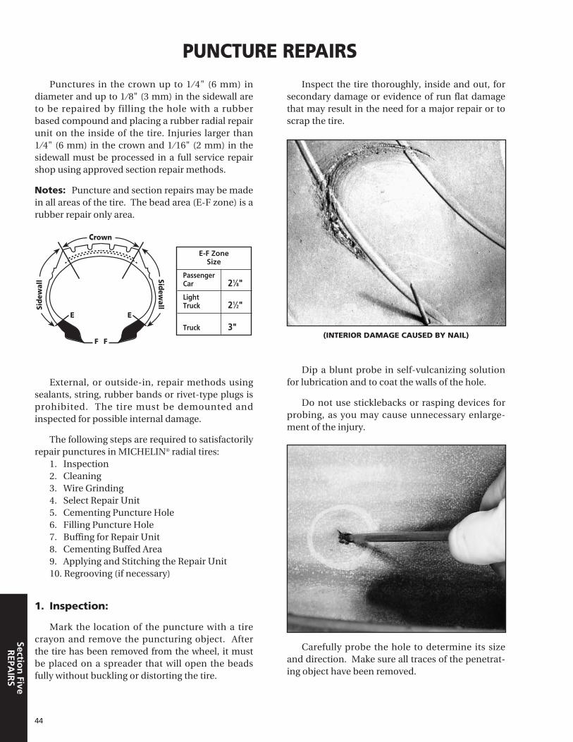
44
Section
FiveR
EPAIR
S
Punctures in the crown up to 1 ⁄ 4" (6 mm) indiameter and up to 1 ⁄8" (3 mm) in the sidewall areto be repaired by filling the hole with a rubberbased compound and placing a rubber radial repairunit on the inside of the tire. Injuries larger than1 ⁄4" (6 mm) in the crown and 1 ⁄16" (2 mm) in thesidewall must be processed in a full service repairshop using approved section repair methods.
Notes: Puncture and section repairs may be madein all areas of the tire. The bead area (E-F zone) is arubber repair only area.
External, or outside-in, repair methods usingsealants, string, rubber bands or rivet-type plugs isprohibited. The tire must be demounted andinspected for possible internal damage.
The following steps are required to satisfactorilyrepair punctures in MICHELIN® radial tires:
1. Inspection 2. Cleaning 3. Wire Grinding 4. Select Repair Unit 5. Cementing Puncture Hole 6. Filling Puncture Hole 7. Buffing for Repair Unit 8. Cementing Buffed Area 9. Applying and Stitching the Repair Unit 10. Regrooving (if necessary)
1. Inspection:
Mark the location of the puncture with a tirecrayon and remove the puncturing object. Afterthe tire has been removed from the wheel, it mustbe placed on a spreader that will open the beadsfully without buckling or distorting the tire.
Inspect the tire thoroughly, inside and out, forsecondary damage or evidence of run flat damagethat may result in the need for a major repair or toscrap the tire.
(INTERIOR DAMAGE CAUSED BY NAIL)
Dip a blunt probe in self-vulcanizing solutionfor lubrication and to coat the walls of the hole.
Do not use sticklebacks or rasping devices forprobing, as you may cause unnecessary enlarge-ment of the injury.
Carefully probe the hole to determine its sizeand direction. Make sure all traces of the penetrat-ing object have been removed.
PUNCTURE REPAIRS
E
Crown
Side
wal
l
E
F F
Sidewall
E-F ZoneSize
PassengerCar 21⁄8"LightTruck 21⁄2"
Truck 3"

45
Sect
ion
Fiv
eR
EPA
IRS
2. Cleaning:
A liquid rubber cleaner/buffer must be used toremove all traces of silicone lubricants on theinside of the tire that will affect adhesion. Spray orsquirt the liquid onto the inner liner, and use aclean cloth or rubber scraper to obtain a uniform,clean dull black appearance.
3. Wire Grinding:
If any damaged wire filaments protrude into theinside of the tire they must be ground off. Use asmall pointed 1 ⁄8" diamond carbide burr mountedin a low speed grinder (1200 rpm max) to grind theends flush with the liner surface. Wire cutters willnot cut close enough. Do not enlarge the holeunnecessarily. If an aluminum oxide stone is usedto trim back damaged wire; it must be mounted ina high-speed (20,000 RPM min.) grinder.
4. Select the proper repair unit:
Center the unit over the puncture and outline anarea 1/2 inch larger than the repair unit.
5. Cementing Puncture Hole:
Apply cement liberally into the puncture hole
by using a cementing tool or small brush.
If the hole is too small to allow cement to flowinto it freely, it is best left alone, as it should not beenlarged needlessly.
6. Filling Puncture Hole:
A great variety of materials are available on themarket to fill puncture holes. These include, butare not limited to, Patch Plug Combination Units,Headless Inserts, and A&B Compound.
Use enough material to completely fill thepuncture and extend beyond the exterior of thetire. Material should be flush with the surface of thetire both inside and out.
Headless Rubber Inserts (Stems) or Patch PlugCombinations may be inserted in several ways.Refer to the individual supplier’s instructions forproper use.
Cut the insert off about 1 ⁄ 32" higher than thesurface of the liner.
7. Buffing For Repair Unit:
Use a wire brush or a fine grit buffing wheel in alow speed grinder (less than 5,000 rpm) to buff theinsert flush with the liner surface. Lightly buff thearea that the repair is to cover to an even velvet-likeRMA-1 texture. Remove all traces of the ventingribs in the repair area. Do not buff through theinner liner or expose any cords of the radial ply.

46
Section
FiveR
EPAIR
S
Remove all buffing dust and debris from insidethe tire with a vacuum cleaner. Brush the buffedarea with a hand held soft wire brush to remove allloose particles.
8. Cementing Buffed Area:
Apply a liberal coat of cement to the buffedarea. Move the puncture to the up position, i.e., 12o’clock, to achieve even drying, as solvents areheavier than air.
Let dry 10-15 minutes depending upon humidity.
Refer to the repair material supplier for pre-ferred drying times.
9. Applying and Stitching the RepairUnit*:
Carefully remove the backing from the adhesiveside of the repair unit, taking care not to touch thetacky surface.
With the beads of the tire relaxed in their normalparallel position, center the patch over the hole andstitch it down thoroughly from the center outwardsto remove trapped air.
Use a corrugated stitcher to make sure that theedges are down tight without creases and folds.
*Check manufacturer’s instructions for cement-ing the repair.
Remove the transparent covering from the topof the repair unit.
Remount the tire to recommended pressureand check for leaks. (Refer to Section Two,Mounting the Tire when remounting the tire.)
10. Regrooving (if necessary):
Please refer to Page 10 of this manual.

47
Sect
ion
Six
RET
REA
DIN
G
For more information on retreading, refer toMichelin MRT Tread Width InformationalGuide”(MYT41805).
For information on proper retread procedureson the X One® tire product line, please consultMichelin for technical guidance.
RETREADING
The purpose of this section is to provide theretreader with the basic procedures required toproperly retread the Michelin® radial tire.
By itself, this section should not be consideredas a guarantee for the proper processing of aretreaded tire, nor is it meant to be used as a substi-tute for a regular training program.
It has been designed to be used as a “workingtool” for the new or inexperienced employee, or asa reference manual for the experienced person.
Since Michelin radial tires are manufactured tovery precise tolerances, it is necessary for similarstandards of accuracy to be maintained during theretreading process. Suitably designed modern
equipment for radial tires must be provided in theretread shop. The proper tread designs, treadwidth, tread compound and tread depths, must beselected according to the type of tire and its antici-pated service.
The tire must be processed with precision tomaintain the design characteristics of theMichelin® radial. As there is very little margin forerror when retreading radial tires, perfectionshould be the only standard acceptable.
For more information contact your localMichelin Representative.
BUFF RADIUS
Charts giving radius specifications should beavailable and referred to on each tire.
The correct radius makes it possible to achievethe correct profile and an even distribution of theresidual rubber covering the belt package. Theamount of residual rubber (undertread) coveringthe belt package should be equal in depth acrossthe surface of the belt package. (Photo A)
Section SixRETREADING
Photo A: Equal undertread
Photo B: Too flat

48
Section
SixR
ETREA
DIN
G
Too flat a radius can leave too much rubber onthe shoulders of the tire. This leads to higher oper-ating temperatures in the shoulder. (Photo B)
Too round a radius leaves too much rubber onthe center of the tire. This leads to higher operat-ing temperatures in the center. (Photo C)
After buffing, a radius template should be usedto verify the buffed radius of the finished tire.(Photo D)
Photo C: Too round
Photo D: Verify the radius on every tire
Photo E: Excess Undertread
UNDERTREAD
The amount of residual rubber (undertread)covering the belt package should be equal in depthacross the surface of the protector belt. Theamount of remaining undertread should be lessthan 3 ⁄32 of an inch.
Too much undertread leads to higher operatingtemperatures. (Photo E)
The remaining undertread must be measured
on every tire to verify that less than 3 ⁄32 of an inchof rubber remains. This can be done by making apilot skive (Photo F) or by using an electronic mea-suring device (Photo G).
Too much undertread at buff makes for toomuch undertread in the finished product. (PhotoH) Control each step. The total amount of under-tread should be no greater than what the tire wasdesigned to contain.

49
Sect
ion
Six
RET
REA
DIN
G
BUFF WIDTH
Charts giving width specifications should beavailable and referred to on each tire.
The correct width makes it possible to achievethe correct profile that allows the design of the tireto evenly distribute stresses.
A tape measure should be used to verify thecasing width after buffing each tire, but prior totrim. The largest possible tread should be used.(Photo I)
After choosing the correct tread, place a sampleon the tire and mark the amount of shoulder trimneeded. The amount of shoulder trim can be fromno trim to a maximum trim of 3 ⁄16 of an inch pershoulder. The trim for mold cure can be up to 3 ⁄8of an inch per side, but the final cure dimensionsshould return the tire to within 3⁄16" per shoulderof the tires original width dimensions.
The shoulder trim angle should not create atrim length greater than 1 ⁄2 of an inch. (See illus-tration to the right.)
Photo F: Pilot skive Photo G: Electronic device
Photo H: Too much total undertread
Photo I: Measure for largest tread
3/16” Trim
1/2” Trim

50
Section
SevenC
OST A
NA
LYSIS
COST ANALYSIS
Each fleet operation is different, but there is oneconsistent goal and that is to achieve the best possi-ble operating cost. This section is designed to pro-vide a guide to determining a Cost Per Mile (CPM).
The simplest CPM is found by dividing the priceof the tire and any retread by the total mileage.While this is an easy calculation, it is very mislead-ing by ignoring many of the added benefits of thetire or the transfer of residual casing value from onelife to another.
Determining CPM by wheel position could pro-vide an important gauge for performance since eachwheel position is a very special case with uniqueoperating requirements. Here are some of the keyelements that need to be considered in any analysis:
1. Total mileage (considers new and retreadmileage for steer, drive and trailer)
2. Residual casing values or casing resale value 3. Requirements of the specific wheel position
(steer, drive and trailer)4. Repairability (dollars spent on additional
mounts and dismounts, repair time and labor)5. Retreadability (additional casing purchases) 6. Fuel efficiency (see section below)7. Total expected casing life8. Labor (scheduled and unscheduled)9. Road call (by shop personnel as well as
Emergency calls)10. Disposal fees 11. Liability Insurance
An estimate of the CPM obtained by differenttires in different wheel positions is shown in theexamples below.
STEER AXLE
a. XZA3™ New Tire Price (estimate) 350.00
b. Residual Casing Value (estimated) - 60.00
c. Total Miles (estimated) ÷ 120,000
d. CPM = $ .00241 per mile
DRIVE AXLE
a. XDA3™ New Tire Price (estimate) 350.00
b. Residual Casing Value (estimated) - 60.00
c. Total Miles (estimated) ÷ 250,000
d. CPM = $ .00116 per mile
YOUR OPERATION Steer Drive Trailer
a. New Tire Price _____________ _____________ _____________
b. Residual Casing Value _____________ _____________ _____________
c. Total Miles _____________ _____________ _____________
d. CPM _____________ _____________ _____________
Section SevenCOST ANALYSIS
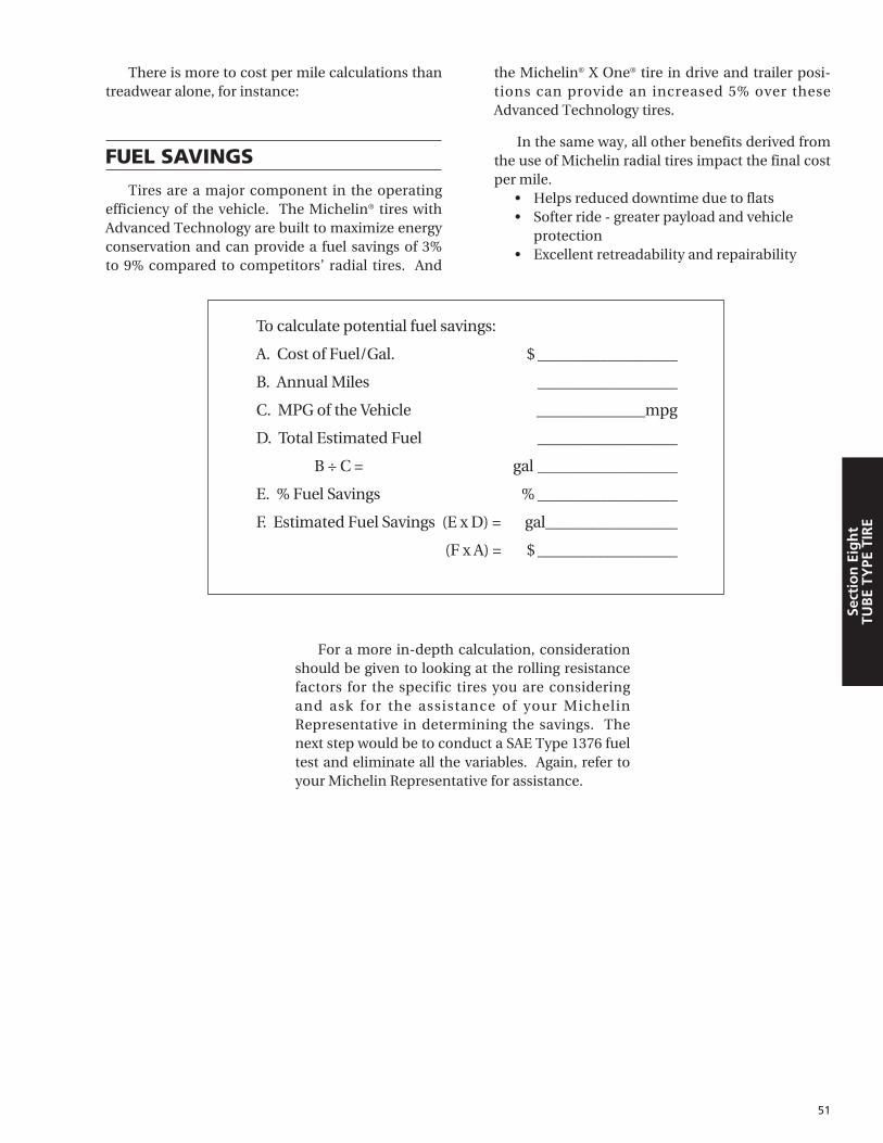
51
Sect
ion
Eig
ht
TUB
E TY
PE T
IRE
There is more to cost per mile calculations thantreadwear alone, for instance:
FUEL SAVINGS
Tires are a major component in the operatingefficiency of the vehicle. The Michelin® tires withAdvanced Technology are built to maximize energyconservation and can provide a fuel savings of 3%to 9% compared to competitors’ radial tires. And
the Michelin® X One® tire in drive and trailer posi-tions can provide an increased 5% over theseAdvanced Technology tires.
In the same way, all other benefits derived fromthe use of Michelin radial tires impact the final costper mile.
• Helps reduced downtime due to flats • Softer ride - greater payload and vehicle
protection • Excellent retreadability and repairability
To calculate potential fuel savings:
A. Cost of Fuel/Gal. $ __________________
B. Annual Miles __________________
C. MPG of the Vehicle ______________mpg
D. Total Estimated Fuel __________________
B ÷ C = gal __________________
E. % Fuel Savings % __________________
F. Estimated Fuel Savings (E x D) = gal_________________
(F x A) = $ __________________
For a more in-depth calculation, considerationshould be given to looking at the rolling resistancefactors for the specific tires you are consideringand ask for the assistance of your MichelinRepresentative in determining the savings. Thenext step would be to conduct a SAE Type 1376 fueltest and eliminate all the variables. Again, refer toyour Michelin Representative for assistance.

52
Section
Eigh
tTU
BE TY
PE TIRE
THE CROSS-PLY (OR BIAS-PLY)TIRE
Cross-ply or conventional tires have a numberof plies which are laid diagonally, criss-crossingone another. As the tire revolves and deflects, thesecrossed plies interact and generate heat – a processthat prematurely ages the components and short-ens the life of the tire.
The number of cross-plies in a conventional tiretends to stiffen its walls, preventing sufficient flexunder heavy load. This causes lateral tread movementwhich impairs road grip and causes tread abrasion.
Definitions:
Aspect Ratio: A nominal number, which repre-sents the section height, divided by the sectionwidth and expressed as a percentageExample: 10.00R20 Aspect Ratio = 10.00
Tube Code: The proper Michelin® tube to beused with Michelin® tube-type tires is designatedby the nominal rim diameter followed by a code. Example: Tube for 10.00R20 Michelin is 20N.
Michelin tubes are made of butyl rubber andmarked with the trade name “AIRSTOP®”. Becauseof the extreme flexibility of the Michelin tire, it is rec-ommended to use an “AIRSTOP” tube. These tubesare made with an overlap splice that is stronger thanthe butt splice used in many other tubes.
Flap Code: When a flap is required, the propersize to use with Michelin tires on each particular rimis designated by a code, the last two digits of whichare the rim diameter or rim width. Unless otherwisespecified, the flap for the preferred rim is normallysupplied with the tire. (E.g. 200-20L or 20x7.50)
TUBELESS OR TUBE-TYPE?As shown below, there are considerable advan-
tages to using tubeless instead of tube-type tires.Whether you choose tube-type or tubeless, Michelinhas the tire to meet your needs. Some Michelin tube-type tires may be run with or without a tube. ContactMichelin to determine tires that apply.
MICHELIN RADIAL TUBELESS TRUCK TIRESTubeless – Simplified mounting requires threecomponents.• No tube and flap• Less downtime due to flats. Fewer road delays• Fewer components
Mismatching of flanges and lock rings is eliminated- No cracked rings or components- No bent or distorted parts
• Slower rate of pressure loss from punctures• Cooler running• Lower profile
PROMOTES:• Increased mileage –
Longer carcass life• Fuel savings• Extra payload• Reduction in
labor and inventory costs
• Greater stability• Improved road
handling• Lower overall
end cost as compared to tube-type tires
TUBELESS (Three Components)
Wheel and Valve Tire
TUBE-TYPE (Seven Components)
SideRing
LockingRing
DiscWheel
Flap Tubeand Valve
Tire
Section EightTUBE-TYPE TIRE

53
Sect
ion
Eig
ht
TUB
E TY
PE T
IRE
MICHELIN® TRUCK TIRE SIZEMARKINGS
Most truck tire sizes are indicated by the sectionwidth in inches, followed by R for radial, followedby the rim or wheel diameter in inches:
TUBE-TYPE TUBELESS10.00R20 11R22.5
10.00 = nominal section 11 = nominal sectionin inches in inches
R = radial R = radial20 = rim or wheel 22.5 = rim or wheel
diameter in inches diameter in inches
NOTE: A “rule-of-thumb” formula for findingequivalent tubeless sizes from tube-type: Takenominal section width and remove all figures afterthe decimal point. Add 1 to nominal section andadd 2.5 to rim diameter.
Example: TUBE-TYPE TUBELESS 8.25R20 = 9R22.5
Nom. Cross Section 8.25 9Remove .25Add 1 to 8 = 9Rim Diameter 20Add 2.5 to Rim Diameter 20 + 2.5 = 22.5Thus we have 9R22.5 Tubeless.
EQUIVALENT SIZESTUBE-TYPE TUBELESS TYPE
8.25R15 9R17.58.25R20 9R22.59.00R20 10R22.5
10.00R20 11R22.511.00R20 12R22.510.00R22 11R24.511.00R22 12R24.5
22.5"20"
Tube-Type
TubelessType

54
Section
Eigh
tTU
BE TY
PE TIRE
A tire cannot perform properly unless it ismounted properly on the correct size rim or wheel.The following are general instructions fordemounting and mounting Michelin® tube-typetires. For detailed instructions on mounting anddemounting truck tires on particular types of rimsand wheels, refer to the instructions of the rim andwheel manufacturer or the RMA wall charts.
Do not re-inflate any tires that havebeen run underinflated or flat withoutcareful inspection for damage. If run-flat damage is detected, scrap the tire.A tire is considered run-flat if it isfound to be 80% below recommendedoperating pressure. This can result inserious injury or death. The tire may bedamaged on the inside and canexplode while you are adding air. Therim parts may be worn, damaged ordislodged and can explosively separate
1. SELECTION OF PROPER COMPONENTSAND MATERIALS:
a. All tires must be mounted with the properMichelin tube and flap (if required) and rim orwheel as indicated in the specification tables.For complete tire specifications, refer to appli-cation specific data books. (See Introductionfor listing.)
b. Make certain that rim/wheel components areproperly matched and of the correct dimen-sions for the tire.
c. Always fit a new Michelin tube in a new mount-ing. Since a tube will exhibit growth in sizethrough normal use, an old tube used in a newmounting increases the possibility of tube creas-ing and chafing, possibly resulting in failure.
d. Always install a new flap in a new mounting.A flap, through extended use, becomes hardand brittle. After a limited time, it will develop aset to match the tire and rim in which it is fitted.Therefore, it will not exactly match a newtire/rim combination.
e. Always install new valve cores, and metal valvecaps containing plastic or rubber seals. Fortires requiring ‘O’ Rings, be sure to properlyinstall a new silicone ‘O’ Ring at every tirechange.
f. Always use a safety device such as an inflationcage or other restraining device that will con-strain all rim/wheel components during anexplosive separation of a multi-piecerim/wheel, or during the sudden release of thecontained air of a single piece wheel that is incompliance with OSHA standards. Never standover a tire or in front of a tire when inflating.Always use a clip-on valve chuck with an in-linevalve with a pressure gauge or a presettable reg-ulator and a sufficient length of hose betweenthe clip-on chuck and in-line valve (if one isused) to allow the employee to stand outsidethe trajectory path when inflating.
2. TIRE AND RIM LUBRICATION:
It is essential that an approved tire mountinglubricant be used. Preferred materials for use asbead lubricants are vegetable oil soaps or animalsoaps, in solution. Never use antifreeze, silicones,or petroleum-base lubricants. Improper ratios ofapproved lubricants and water may have a harmfuleffect on the tire and wheel.
The lubricant serves the following three purposes:• Minimizes the possibility of damage to the tire
beads from the mounting tools. • Eases the insertion of the tire onto the rim by
lubricating all contacting surfaces. • Assists proper bead seating (tire/rim centering)
and helps to prevent eccentric mountings.
Apply a clean lubricant to all portions of thetire bead area and the exposed portion of the flapusing sufficient but sparing quantities of lubricant.Also, lubricate the entire rim surface. Avoid usingexcessive amounts of lubricant, which canbecome trapped between the tire and tube andcan result in tube damage and rapid air loss.
CAUTION: It is important that tire lubricant beclean and free of dirt, sand, metal shavings or other
GENERAL INSTRUCTIONS FOR MOUNTING ANDDEMOUNTING TUBE-TYPE TIRES
®

55
Sect
ion
Eig
ht
TUB
E TY
PE T
IRE
hard particles. These particles may lodge betweenthe tube and the flap edges resulting in splits in thetube. The following practice is recommended:
a. Use a fresh supply of tire lubricant each daydrawing from a clean supply and placing thelubricant in a clean portable container.
b. Provide a cover for the portable containerand/or other means to prevent contaminationof the lubricant when not in use. For lubricantsin solution, we suggest the following method,which has proven to be successful in minimizingcontamination and preventing excess lubricantfrom entering the tire casing: provide a specialcover for the portable container that has a fun-nel-like device attached. The small opening ofthe funnel should be sized so that when a swabis inserted through the opening into the reserveof lubricant and then withdrawn, the swab iscompressed, removing excess lubricant. Thisallows the cover to be left in place providingadded protection. A mesh false bottom in thecontainer is a further safeguard against contam-
inants. The tire should be mounted and inflatedpromptly before lubricant dries.
3. PREPARATION OF WHEELS, RIMS ANDTIRES:
Never weld or apply heat to a rim or wheel onwhich a tire is mounted.
a. Always wear safety goggles or face shields whenbuffing or grinding rims or wheels.
b. Inspect wheel/rim assemblies for cracks, distor-tion, deformation of flanges, side rings, lockrings, etc. Using a file and/or emery cloth,smooth all burrs, welds, dents, etc. that are pre-sent on the tire side of the rim. Inspect the con-dition of bolt holes on the wheels.
c. Remove rust with a wire brush and apply a rustinhibiting paint.
d. Remove any accumulation of rubber or greasethat might be stuck to the tire, being carefulnot to damage it. Wipe the beads down with adry rag.
Any inflated tire mounted on a rimcontains explosive energy. The use ofdamaged, mismatched or improperlyassembled tire/rim parts can causethe assembly to burst apart withexplosive force. If you are struck byan exploding tire, rim part or the airblast, you can be seriously injured orkilled. Do not attempt to dismountthe tire while the assembly is stillinstalled on the vehicle. Use propertools to demount or mount rim parts.Never use a steel hammer to seat rimparts- use only rubber, plastic, orbrass-tipped mallets. Striking awheel/rim assembly with a hammerof any type can damage the tire orwheel and endanger the installer.Use a steel duck billed hammer onlyas a wedge. Do not strike the headof a hammer with another hard-facedhammer- use a rim mallet.
DEMOUNTING TUBE-TYPE TIRES 1. If a tire has been running underinflated or if any
damage to the tire or wheel is suspected, thevalve core should be removed prior to removingthe tire/wheel assembly from the vehicle axle.This is to prevent a possible accident.
2. Before unlocking any side ring or lock ring,remove the valve core and allow the tire todeflate completely.
3. Remove all rim or wheel parts.
MOUNTING OF TUBE-TYPE TIRES1. Insert the proper size Michelin® tube into the
tire and partially inflate (3 psi) to round out thetube (with larger sizes it may be necessary touse bead spreaders – see Page 56 for mountinginstructions).
2. Insert the valve through the flap valve hole.
TUBE-TYPE TIRE MOUNTING/DEMOUNTING

56
Section
Eigh
tTU
BE TY
PE TIRE
(Make sure the reinforced patch that is directlyover the flap valve hole is facing outwards.) Theninsert the remainder of the flap into the tire.
3. Check the flap wings to insure against folding.This is easily accomplished by placing yourhand into one tire side, then the other, and thenrunning your hand along the entire flap wing.
4. Inflate the tube until the flap is secured againstthe tire wall and the beads start to spread apart,making sure not to exceed 3 psi.
5. Apply a proper tire lubricant to both beads andthe exposed flap. Make sure that excess lubri-cant does not run down into the tire.
6. Place tire, tube and flap on the wheel or rim,taking care to center the valve in the slot.
7. Fit side ring and lock ring, insuring that they areproperly positioned, locked, and are correct forthe ‘fitment’.
MOUNTING OF TUBE-TYPE TIRESUSING MANUAL SPREADERS: 1. Follow steps 1 through 3 of the “Mounting of
Tube-Type Tires”. However, before insertingthe flap into the tire, position two bead spread-ers in the following manner:
a. Place the first at a 90° angle to the valve.(Flap is positioned between the spreader andthe tube.)
b. Place the second directly opposite the first.
c. Spread the beads and insert the flap.
d. Close the beads, remove spreaders.
2. Follow steps 4 through 7 of the “Mounting ofTube-Type Tires”.
MOUNTING OF TUBE-TYPE TIRESUSING AUTOMATIC SPREADERS:1. Spread the tire beads.
2. Inflate the tube to approximately 3 psi.
3. Insert the tube into the tire. Apply a proper tirelubricant to the inside and outside surfaces ofboth beads and to that portion of the tube thatappears between the beads. Make sure that
excess lubricant does not run down into the tire.
4. Insert the valve through the flap valve hole. (Asmentioned, the flap reinforced valve area mustface outwards.) Insert the remainder of the flapinto the tire.
5. Close the beads.
6. Follow steps 4 through 7 of the “Mounting ofTube-Type Tires”.
INFLATION OF TUBE-TYPE TIRES1. An air line with an extension (30" minimum),
in-line gauge, and a clip-on valve chuck shouldbe used for inflation. Remove valve core andlay the assembly flat on the ground. Using anapproved restraining device, inflate partially toseat beads. While the tire is still in the restrain-ing device, make sure all rim components arecentered and locked properly. If not, the tiremust be deflated, broken down, re-lubricatedand re-inflated. Do not attempt to seat the lockring by means of a hammer.
2. Deflate the tire by removing the air line. This isto allow the tube to relax thus eliminating anywrinkles or uneven stretching that may haveoccurred during primary inflation.
3. Install the valve core and, using a safety cage,or other approved restraining device meetingOSHA standards, re-inflate the tire to the pres-sure shown on the sidewall in order to insureproper bead seating. Then adjust the tire to theproper operating pressure. Never stand over atire or in front of a tire when inflating. Alwaysuse a clip-on valve chuck with an in-line valvewith a pressure gauge or a presettable regulatorand a sufficient length of hose between the clip-on chuck and in-line valve (if one is used) toallow the employee to stand outside the trajec-tory path when inflating.
4. Re-inspect the assembly for proper positioningof all components.
5. Check for leaks and install a suitable valve cap.
6. Do not re-inflate any tires that have been rununderinflated or flat without careful inspec-tion for damage. If runflat damage is detected,scrap the tire. A tire is considered run-flat if itis found to be 80% below recommended oper-ating pressure.

57
Sect
ion
Nin
eA
PPEN
DIX
Section NineAPPENDIX
Quantity S.I. Units Other Units
Length m 1 inch (") = 0.0254 m or 25.4 mm(meter) 1 mile = 1609 m (1.609 km)
1 kilometer = 0.621 mile
Mass kg 1 pound (lb) = 0.4536 kg(Kilogram) 1 kilogram (kg) = 2.205 lbs.
Pressure kPa 1 bar* = 100 kPa(Pascal) 1 psi = 6.895 kPa
1 pound per square inch1 kg/cm2 - 98.066 kPa
Speed m/s 1 kilometer per hour (kph)* = (meter per 0.27778 m/s
second) 1 mile per hour (mph) = 0.4470 m/s (or 1.60935 kph)
Units of Measurement
Load Range/Ply Rating
Pressure Unit Conversion Table
* Non S.I. unit to be retained for use in specialized fields.
* Values in psi and kg/cm2 rounded to the nearest practical unit.
kPa bar lb/in2* kg/cm2*
100 1.0 15 1.0
150 1.5 22 1.5
200 2.0 29 2.0
250 2.5 36 2.5
300 3.0 44 3.1
350 3.5 51 3.6
400 4.0 58 4.1
450 4.5 65 4.6
500 5.0 73 5.1
550 5.5 80 5.6
600 6.0 87 6.1
650 6.5 94 6.6
700 7.0 102 7.1
750 7.5 109 7.7
800 8.0 116 8.2
850 8.5 123 8.7
900 9.0 131 9.2
950 9.5 138 9.7
1000 10.0 145 10.2
1050 10.5 152 10.7
Speed Speed Speed Speed Speed Speed
Symbol (kph) mph Symbol (kph) mph Symbol (kph) mph
A1 5 2.5 A7 35 22.5 F 80 50
A2 10 5 A8 40 25 G 90 56
A3 15 10 B 50 30 J 100 62
A4 20 12.5 C 60 35 K 110 68
A5 25 15 D 65 40 L 120 75
A6 30 20 E 70 43 M 130 81
N 140 87
Speed Symbol
The ISO* SPEED SYMBOL indicates the speed at which the tire can carry a load correspondingto its Load Index under service conditions specified by the tire manufacturer.**
* International Standardization Organization** Exceeding the legal speed limit is neither recommended nor endorsed.
B – 4 F – 12 L – 20
C – 6 G – 14 M – 22
D – 8 H – 16
E – 10 J – 18
GENERAL INFORMATION

58
Section
Nin
eA
PPEND
IX
Approximate weight of materials
Most materials and commodities vary in weight the following weights should be usedonly for approximation purposes. Exact weights should be obtained from localsources when making recommendations for truck or tractor-trailer equipment.
Lbs. per No. of Cu. Ft. Pounds Per:
Beans, dry 60 Bushel
Cement, Portland — 94 Bag
Clay and Gravel, dry 100 2700 Cu. Yd.
Clay and Gravel, wet 65 1755 Cu. Yd.
Coal, Hard or Anthracite, broken 52-57 1400-1540 Cu. Yd.
Coal, Soft or Bituminous, solid 79-84 2134-2270 Cu. Yd.
Concrete 120-155 3200-4185 Cu. Yd.
Corn, in ear — 70 Bushel
Corn, shelled —- 56 Bushel
Corn Syrup 86 11.5 Gallon
Crude Oil 52 700 100 Gal.
Fuel Oil 52-74 695-795 100 Gal.
Gasoline 45 600 100 Gal.
Gravel 100-120 2700-3240 Cu. Yd.
Gravel and Sand, dry, loose 90-100 2430-2862 Cu. Yd.
Gravel and Sand, dry, packed 110 2970 Cu. Yd.
Gravel and Sand, wet 120 3240 Cu. Yd.
Milk —- 845-865 100 Gal.
Paper, average weight 58
Oats —- 32 Bushel
Potatoes, White or Irish — 60 Bushel
Petroleum — 800 100 Gal.
Sand, dry, loose 90-106 2430-2860 Cu. Yd.
Sand, moist, loose 120 3240 Cu. Yd.
Soy Beans —- 60 Bushel
Water 62.4 835 100 Gal.
Wheat —- 60 Bushel

59
Sect
ion
Nin
eA
PPEN
DIX
Load Index
The ISO LOAD INDEX is a numerical code associated with the maximum load a tire can carry at the speed indicated by its SPEED* SYMBOL under service conditions specified by the tire manufacturer. (1 kg = 2.205 lbs.)
100 800 1,765
101 825 1,820
102 850 1,875
103 875 1,930
104 900 1,985
105 925 2,040
106 950 2,095
107 975 2,150
108 1,000 2,205
109 1,030 2,270
110 1,060 2,335
111 1,090 2,405
112 1,120 2470
113 1,150 2,535
114 1,180 2,600
115 1,215 2,680
116 1,250 2,755
117 1,285 2,835
118 1,320 2,910
119 1,360 3,000
120 1,400 3,085
121 1,450 3,195
122 1,500 3,305
123 1,550 3,415
124 1,600 3,525
125 1,650 3,640
126 1,700 3,750
127 1,750 3,860
128 1,800 3,970
129 1,850 4,080
130 1,900 4,190
131 1,950 4,300
132 2,000 4,410
133 2,060 4,540
134 2,120 4,675
135 2,180 4,805
136 2,240 4,940
137 2,300 5,070
138 2,360 5,205
139 2,430 5,355
140 2,500 5,510
141 2,575 5,675
142 2,650 5,840
143 2,725 6,005
144 2,800 6,175
145 2,900 6,395
146 3,000 6,610
147 3,075 6,780
148 3,150 6,940
149 3,250 7,160
150 3,350 7,390
151 3,450 7,610
152 3,550 7,830
153 3,650 8,050
154 3,750 8,270
155 3,875 8,540
156 4,000 8,820
157 4,125 9,090
158 4,250 9,370
159 4,375 9,650
160 4,500 9,920
161 4,625 10,200
162 4,750 10,500
163 4,875 10,700
164 5,000 11,000
165 5,150 11,400
166 5,300 11,700
167 5,450 12,000
168 5,600 12,300
169 5,800 12,800
170 6,000 13,200
171 6,150 13,600
172 6,300 13,900
173 6,500 14,300
174 6,700 14,800
175 6,900 15,200
176 7,100 15,700
177 7,300 16,100
178 7,500 16,500
179 7,750 17,100
180 8,000 17,600
181 8,250 18,195
182 8,500 18,745
183 8,750 19,295
184 9,000 19,845
185 9,250 20,400
186 9,500 21,000
187 9,750 21,500
188 10,000 22,050
189 10,300 22,720
190 10,600 23,400
191 10,900 24,040
192 11,200 24,700
193 11,500 25,360
194 11,800 26,020
195 12,150 26,800
196 12,500 27,565
197 12,850 28,355
198 13,200 29,110
199 13,600 30,000
200 14,000 30,870
201 14,500 31,980
LoadIndex kg lbs.
LoadIndex kg lbs.
LoadIndex kg lbs.
*Exceeding the legal speed limit is neither recommended or endorsed.

SET-UP INSTRUCTION PROCEDURES
TOOLS:• Chalk Line (no chalk) • Metric Tape• 1 pair of Jack Stands • Toe-Scribe• 2 Cans of White Spray Paint • Large Plastic Bags• Vehicle Jack (10 Tons) • Flashlight• Line Level and Wheel Chocks • 1 T-45A Tire Iron
Refer to Michelin Video, ATTACC Plus (MWV41200)for reference.
SURFACE: Inspection site should be fairly level,use Line Level if necessary to determine slope.
STEER/DRIVE TIRES: Note: Tread Design, DOT,Tread Depth, PSI, Tire Conditions and mileage, andall normal pertinent vehicle information.
VEHICLE POSITIONING:
1. Drive vehicle straight into inspection site, atleast 3 full vehicle lengths, to ensure it’s straightinto site. Driving into and backing out of thework area several times will insure the vehicle’ssuspension components are properly relaxed toachieve proper measurements.
2. Allow vehicle to roll to a stop, shut-off theengine and let up on the clutch.
3. Let vehicle fully stop by transmission, nobrakes.
4. Engage tractor parking brakes and take out ofgear, place Wheel Chocks on the drive tires.
MEASUREMENTS:
Record all measurements.
Front of Vehicle:
1. Measure steering axle skew from the front of theoutside U-bolt to the zerk fitting (or bolt) on thefront spring pin perch.
2. Measure for straight ahead steering from the innerwheel flange to edge of the leafspring or frame on
both sides of the vehicle to insure the steer tiresare straight ahead (tolerance is 1⁄32" or 1 mm sideto side). Adjust the steering wheels as necessary tocome within tolerance. Mark the steering wheelcolumn with a crayon for future reference.
3. Measure for steering axle offset from the framerail to the tire rib on both sides.
4. Steering Stops: insure they exist and measurelength. Stops control the angle of the turn andmay be a consideration if abnormal steer tirewear is present.
Rear of Vehicle:
1. Measure for drive axle offset by measuring, ateach drive axle wheel position, from the innerwheel flange to the inside of the frame rail (tol-erance: 3 ⁄16" or 5 mm side to side).
2. Check ride height by measuring the distancefrom the lower part of the frame rail to the bot-tom of the air spring (bag) housing.
3. Measure for tandem axle skew by measuringbetween the rim flanges. Kneel between the out-side of the tires and hook the metric tape at hub-height on one and by using a swinging arc on theother, determine the shortest distance betweenthem. Take a similar measurement on the otherside of the vehicle (tolerance is 1 ⁄8" or 3 mm).
4. Measure for drive axle thrust by using the stringfrom the front drive axle to the steer position.Attach the string to the drive tire at hub height,bring it across the rear sidewall, move to thesteering axle, bring the string in toward the frontrim until it touches the drive tire's front sidewalland measure the distance between the stringand disc face of the rim (just below the dustcap). Repeat this method on the other side.
With all data recorded, review measurement ofdrive axle offset. Any significant drive axle offset, iffound (�3 ⁄16" or �5 mm), must be factored intothe readings of drive axle thrust as determinedabove by adding or subtracting the offset from theappropriate side.
Draw a picture of the steer and drive axle orien-tation using recorded axle skew measurements.
60
VEHICLE ALIGNMENT – FIELD METHODATTACC PLUS SYSTEM
Section
Nin
eA
PPEND
IX

61
Sect
ion
Nin
eA
PPEN
DIX
Drive axle skew tolerance is based on wheelbase. 19 ⁄32" or 15 mm < 150", 3 ⁄4" or 20 mm 150-200", 1" or 25 mm > 200".
5. Check front end components and toe by jackingup front end. Place the floor jack under the axlefor support, use the T-45A iron to lift the tireand feel for bearing play, and in the wheel handhole to check for kingpin play. Using the spraypaint, lightly spray the center of tire tread and,with the toe scribe, scribe the tire. While slowlyrotating the tire, check for lateral and radialrunout by observing the scribed line.Additionally, observe the relative relationshipbetween the wheel flange and the GG ring onthe lower sidewall of the tire to determine prop-er mounting of the tire on the wheel. Repeatthis process on the other steer tire. Check forsteer ahead by referencing the mark on thesteering wheel column and lower the vehicle onthe folded plastic bags. Plastic should be foldedto just larger than the tire footprint so that no
part of the steer tires will make contact with theground. Gently shake the vehicle to settle thesuspension system, confirm steer ahead andmeasure toe between the scribe lines, first rear,then front, to determine relative toe. Do thiswith the paint cans on the ground, centered onthe scribe line and measure the distancebetween the lines on the left and right tire at thepaint can height. Subtract front from rear: posi-tive result indicates toe-in, negative is toe-out.At this paint can height: total toe-in should be 1mm �1 mm.
6. If checking for camber, with wheels straightahead, drop a plumb line off the front fender overthe tire assembly center and measure the dis-tance between the string and rim flange at the topand bottom. Divide your difference by 10 to con-vert mm to degrees. Use the paint can to extendout from the fender if necessary. Repeat the pro-cedure on the other steer position. Consider anyfloor slope and matching air pressures.
Spring to Flange
Spring to Flange
Steer Offset
Steer Offset
String to wheelfor drive axle thrust
String to wheelfor drive axle thrust
Front Tandem Axle Skew
Front Tandem Axle Skew
Drive Axle Offset
Drive Axle Offset
Grease Zerk to U-Bolt
Grease Zerk to U-BoltDrive Axle Offset
Drive Axle Offset
ATTACC PLUS Worksheet

TIRE MANAGEMENT
The goal of every truck operator is to achievethe lowest possible operating cost, taking advan-tage of the performance built into each high techMichelin radial truck tire. Tire maintenance, toinclude proper air pressures, repairs, vehicle align-ment, and retreading, are all keys to help ensuremaximized performance and extended casing life.
Over the past 10 years, a number of operationaland product changes have occurred that should beconsidered when establishing tire use patterns.The single most important point of any program is“Know your customer”.
Tire Changes
1 . New Tires: Today’s wider treads and deepertread depths provide more original tread miles.The tire arrives at the retreader with more timein service, more miles, and exposure to roadconditions.
2. Retread Changes: Wider treads, new treaddesigns, and new compounds have increasedretread mileages.
Vehicle Changes
1. Longer Trailers: There has been a move from40' to 48' and 53' trailers as standards in thecontract and private carriage business.
2. Wider Trailers: Widths have increased from96" to 102". The combination of longer andwider trailers increases the frequency of theduals being curbed.
3. Setback Front Axles: Moving the steer axleback increases stress on steer tires and load effi-ciency by allowing better load distribution. Theresult is higher average axle loads.
4. Electronic Engines: Better engine controland more efficient operation improve the abili-ty of the vehicle to maintain higher cruisespeeds.*
Operational Changes:
1. Speed limit: The national limit has continual-ly increased in the past decade.*
2. GVW: With the Surface TransportationAssistance Act of 1983 , the weight limits wentfrom 73,280 lbs. to 80,000 lbs. With setbackaxles, you can realistically load to 80,000 lbs.
3. Greater Vehicle Utilization: More loadedmiles mean productivity gains.
All of these changes lead to the casing arrivingat the retread stage with a higher level of fatigue.To utilize these casings to their maximum, casingmanagement should be employed in the selectionof the retread.
CASING MANAGEMENT TODAY
Highway fleets typically employ the casingmanagement pattern below:
Position of Tire First Position of First SubsequentUsed On Retread Use Retread Use
Steer � Drive or Trailer � Drive or Trailer
Drive � Drive � Drive or Trailer
Trailer � Trailer � Trailer
In terms of casing fatigue, the severity of use isas follows:
• Drive Axle – most fatigue. New drive tires (lugtype) often can accumulate twice as many miles(or more) before retreading than new steer ortrailer tires can. The same is true for drive axlelug type retreads. The tires also run hotter(deeper tread) and with more torque.
62
Section
Nin
eA
PPEND
IX
CASING MANAGEMENT
* Exceeding the legal speed limit is neither recommended nor endorsed.

63
Sect
ion
Nin
eA
PPEN
DIX
• Steer Axle – moderate fatigue. Steer axle tiresoperate at higher average loads than drive ortrailer tires (20 to 40% higher). However, theywear out sooner than drive tires and are movedto lighter axles in the retread stage.
• Trailer Axle – least fatigue. The trailer tirestarts life with a shallow (cooler) tread and isusually retreaded with a shallow retread.Annual miles are low. The trailer tire casingusually sees more curb abuse, neglect, and oldage problems.
Thus, the practice of retreading new drive axletires back to the drive axle puts the most highlyfatigued casing back onto the most highly stressedwheel position.
CASING MANAGEMENT FOR THE FUTURE
The following guidelines are recommended insorting casings for their next tread life. Such a sort-ing would allow the fleet and retreader to makebetter decisions regarding the handling and utiliza-tion of casings recovered from 6 x 4, 4 x 2, and trail-er applications. Casings which are judged to bemore “highly fatigued” should be retreaded in oneof two ways:
1 . A low rolling resistance/low heat retread rubberin rib and drive (consult your retread supplier).
2. A shallow retread (no more than 15 ⁄32").
These retreads will reduce the operating tem-perature in the crown of the tire.
Determining which tires are “highly fatigued”requires a working knowledge of each fleet's individ-ual operation. The following guidelines can be used:
1. Two or more repairs on the casing.
2. Heavy side wall abrasion.
TREAD SELECTION MATRIX
In view of the above, it would seem best toadopt the casing management pattern below fortires in highway service:
Position of Tire First Position of First SubsequentUsed On Retread Use Retread Use
Steer � Drive or Trailer � Trailer
Drive � Trailer � Trailer
Trailer � Drive or Trailer � Trailer
RETREAD RECOMMENDATIONS:
1. Follow the retread manufacturer's recommen-dations.
2. Use the preferred tread size.
3. Buff to the correct crown radius.
4. Use pilot skives to measure undertread. 2 ⁄32" to3 ⁄32" is all that should remain when buffing iscomplete.
PREVIOUS SERVICE LIFE
In light of all these conditions, guidelines andrecommendations, the purchaser of casings forretreading should proceed with caution. Use thetread selection matrix when previous service life isunknown.

64
COLD CLIMATE PRESSURE CORRECTION DATA
Section
Nin
eA
PPEND
IX
Because the air pressure inside a tire willdecrease when the vehicle is taken from a warmenvironment to a cold one, some adjustments maybe necessary when adjusting the tire pressures of avehicle to be operated in very cold temperatures.
These adjustments are only necessary if thepressures are verified and adjusted inside a heatedgarage with an air supply that is also at the higherroom temperature. (No adjustment necessary ifdone outside.)
In extreme cases, the following table should be
used to ensure that the operating pressure anddeflection of tires are adequate at the outside ambi-ent temperature.
Using the load and pressure charts below, deter-mine the appropriate “Recommended Pressure”required for the axle load. Then find the same pres-sure down the left column of the table to the right.Going across to the relevant outside ambient temper-ature you will find the corrected inflation pressure tobe used.
Adjusted Inflation Pressure (psi)(when inflating indoors at 65°F [18°C])
Do not exceed maximum pressure capacity of the wheel. Consult wheel manufacturer.
°F°C
Recommended Outside Ambient TemperaturePressure 50° 40° 30° 20° 10° 0° -10° -20° -30° -40° -50°
(psi) 10° 4° -1° -7° -12° -18° -23° -29° -34° -40° -46°
75 78 80 81 83 86 88 90 92 95 98 100
80 83 85 87 89 91 93 96 98 101 104 107
85 88 90 92 94 97 99 102 104 107 110 113
90 93 95 98 100 102 105 108 110 113 116 119
95 98 101 103 105 108 111 113 116 119 123 126
100 103 106 108 111 113 116 119 122 125 129 132
105 109 111 114 116 119 122 125 128 132 135 139
110 114 116 119 122 125 128 131 134 138 141 145
115 119 122 124 127 130 133 137 140 144 148 151
120 124 127 130 133 136 139 143 146 150 154 158
125 129 132 135 138 141 145 148 152 156 160 164
130 134 137 140 144 147 150 154 158 162 166 171
For example:• A log truck in Alaska has a front axle loaded weight of 12,700 lbs..• The truck is equipped with 11R24.5 XZY-2™ LRG.• The recommended pressure for this fitment is 100 psi.• The truck is parked overnight in a heated garage.• The outside high forecasted for today is -20ºF.• The tire pressures are checked and adjusted prior to leaving the heated garage.According the the chart below, the tires should be adjusted to: 122 psi.

65
Sect
ion
Nin
eA
PPEN
DIX
Low Air PressureThis is the number one (along with improper
alignment) tire maintenance issue in the industry.The goal is to maintain a recommended/fleet targetpressure based on the application and vary nomore than �10 psi. Outside of this range, casingfatigue and irregular wear could cost in a range of$15 to $30.00 on a $300.00 tire.
Valve CapsSlow air loss is the primary result of missing or
faulty valve caps. Properly installed and maintainedvalve caps function as a secondary air seal andmeans to keep debris away from the valve core.Always install a new metal valve cap containing arubber or plastic seal. Consider a flow-through typesystem to improve your maintenance program. Theresulting annual expense from missing valve caps/airloss may result in $5 to $15.00 per occurrence.
Dual Mismatched Air PressureThe goal is to maintain tires in dual with equal
pressure and within the target range of �10 psi.Mismatched pressures can cause a permanentirregular wear pattern to develop and within justa matter of weeks can potentially be a cause ofearly tire removal. The matched tire will also beaffected by this difference. Based on a loss of 5 to
20% of treadlife, a $30.00 cost may be associatedwith this situation.
Dual Mismatched HeightThe best method of avoiding damage due to
having tires of unequal circumferences is to inspectand match tires so that the average diameter onone axle is within 1 ⁄4 inch of the other. Based on aloss of 5 to 20% of treadlife, a $30.00 cost may beassociated with this situation.
OverinflationAgain, the goal is to maintain a recommended/
fleet target pressure based on the application andvary no more than �10 psi. Overinflated tires aremore likely to be damaged by impact breaks andaccelerated wear costing from 7 to 15% of life. A cost factor in a range of $15 to $30.00 could beassociated with overinflation.
Irregular WearProper air pressure maintenance and a total
vehicle alignment program can eliminate mostirregular wear. An occurrence of irregular wear, onaverage, is associated with a 12% loss of tread life,or $15 to $36.00. It is also not uncommon for irreg-ular wear to cause a loss of up to 50% of usabletread, resulting in a much higher cost.
SIX CRITICAL FUNDAMENTALS THAT COST MONEY
Size: 275/80R22.5Overall Diameter: 40.1
Inches (decimal) Inches (fraction) Millimeters Degrees
0.03125 1/32 0.8 0.040.06250 1/16 1.6 0.090.09375 3/32 2.4 0.130.12500 1/8 3.2 0.180.15625 5/32 4.0 0.220.18750 3/16 4.8 0.270.21875 7/32 5.6 0.310.25000 1/4 6.4 0.360.28125 9/32 7.1 0.400.31250 5/16 7.9 0.450.34375 11/32 8.7 0.490.37500 3/8 9.5 0.540.40625 13/32 10.3 0.580.43750 7/16 11.1 0.630.46875 15/32 11.9 0.670.50000 1/2 12.7 0.71
CONVERSION TABLE

66
Section
Nin
eA
PPEND
IX
DOT SIDEWALL MARKINGS
New Tire markings required by the Department of Transportation:
DOT XX XX XXX 0100Meets Manufacturer Tire Size Tire Type Date of ManufactureDOT 2-digit 2-digit Code (Week/Year)Standards Identification (Mold/Chamber (Optional) Identification
Mark Identification Mark) Mark
Truck Tire Retread markings as required by the Department of Transportation:
R XX XX XXX 0100Indicates Manufacturer Tire Size Tire Type Date of ManufactureRetread 2-digit 2-digit Code (Week/Year)
Identification (Mold/Chamber (Optional) IdentificationMark Identification Mark) Mark
Additional State Requirements for Truck Tire Retread markings:
R XX XX XXX 0100 RSF2Indicates Manufacturer Tire Size Tire Type Date of Manufacture RS indicatesRetread 2-digit 2-digit Code (Week/Year) retread was
Identification (Mold/Chamber (Optional) Identification produced underMark Identification Mark) Mark Industry Retread
Standards;F2 indicatesthe tire isacceptable forsteer axle use and has beenretreaded twice.
All new tires sold in the United States must havea DOT number cured into the lower sidewall. Allretreaded tires must also have an additional DOTaffixed to their sidewalls as well. It is recommend-ed that this marking be placed in the lower sidewallnear the original DOT code. Certain states mayrequire labeling in addition to the Federal require-ments certifying compliance with the Industry
Standard for Retreading. Tires manufactured priorto the year 2000 used 3 digits rather than 4, the firsttwo numbers indicating the week and the last oneindicating the year of production, followed by asolid triangle to indicate the 1990’s. Examples (i. e.,B6 DO A83 x 2104) of these codes and markings areshown below.

Sect
ion
Nin
eA
PPEN
DIX
Before servicing any truck wheel, it is essentialto know what type of mounting system you will beworking on. Three basic types of mounting systemsare commonly used on commercial vehicles inNorth America. See TMC RP 217A, AttachingHardware for Disc Wheels, for more detailed infor-mation on fasteners.
Hub Piloted Disc Wheels are designed to centeron the hub at the center hole or bore of the wheel.The wheel center hole locates the wheel on pilotsbuilt into the hub. Hub piloted wheels are usedwith two-piece flange nuts which contact the discface around the bolt hole. Only one nut on each
stud is used to fasten single or dual wheels to avehicle. All stud and nut threads are right hand.Hub piloted wheels have straight through boltholes with no ball seat, which provides a visual wayof identifying them. (Figure 1)
Stud Piloted Disc Wheels are designed to becentered by the nuts on the studs. The seatingaction of the ball seat nuts in the ball seat bolt holescenters the wheels. Stud piloted dual wheelsrequire inner and outer cap nuts. Fasteners withleft hand threads are used on the left side of thevehicle and those with right hand threads are usedon the right side of the vehicle. (Figure 2)
HUB AND STUD PILOTED WHEEL TYPES
Figure 1: Hub Piloted Disc Wheel System
Figure 2: Stud Piloted Disc Wheel System
WARNING: Correct Components must beused. It is important to note that some hub pilotedand stud piloted wheels may have the same boltcircle pattern. Therefore, they could mistakenly beinterchanged. Each mounting system requires itscorrect mating parts. It is important that the prop-er components are used for each type of mounting,and that the wheel is fitted to the proper hubs.
If hub piloted wheel components (hubs, wheels,fasteners) are mixed with stud piloted wheel com-ponents, loss of torque, broken studs, cracked
wheels and possible wheel loss can occur sincethese parts are not designed to work together.
Mixing hub pilotedand stud piloted wheelswill not allow the innercap nut to fit into theinner wheel and willresult in the inner capnut interfering with theouter wheel. ( Figure 3)
Figure 3: Improper Mounting
67

Ball set, studpiloted wheels shouldnot be used withflange nuts becausethey have larger boltholes and do nothave sufficient areanear the bolt hole tosupport the flangenut. Slippage mayoccur. Also the cen-ter hole is too large tocenter the wheel. (Figure 4)
It is also important to note that the hardwarefor stud and aluminum wheels cannot be arbitrari-ly mixed. If stud and aluminum wheel hardware
are mixed, loss of clamp load, broken studs,cracked wheels, or possible wheel loss can occursince these parts are not designed to work together(See Figures 5 and 6.). Refer to TMC RP 608a, BrakeDrums and Rotors, and TMC RP 217A, AttachingHardware for Disc Wheels.
68
DISC WHEEL INSTALLATION PROCEDURE—RECOMMENDED MOUNTING TORQUE FOR DISC WHEELS
Section
Nin
eA
PPEND
IX
Figure 4: Improper Mounting
Figure 5: Correct Figure 6: Incorrect
Torque LevelMounting Type Nut Tread Ft-Lb (Oiled)
Hub-piloted with flange nut 11/16”–16 300-400
M20 x 1.5 280-330
M22 x 1.5 450-500
Ft-Lb (Dry)
Stud-piloted, double cap nut 3/4”–16 450-500
Standard type (7/8” radius) 1-1/8”–16 450-500
Stud-piloted, double cap nut 15/16”–12 750-900
Heavy duty type (1-3/16’ radius) 1-1/8”–16 750-900
1-5/16”–12 750-900
Notes:1. If using specialty fasteners, consult the manufacturer for recommended torque levels.
2. Tightening wheel nuts to their specified torque is extremely important. Under-tightening, which results inloose wheels, can damage wheels, studs and hubs and can result in wheel loss. Over-tightening can dam-age studs, nuts and wheels and result in loose wheels as well.
3. Regardless of the torque method used, all torque wrenches, air wrenches and any other tools should becalibrated periodically to ensure the proper torque is applied.
Reprinted with permission from TMC RP 222A, User’s Guide to Wheels and Rims, published by the Technology & Maintenance Council(TMC) of the American Trucking Associations, 2200 Mill Road, Alexandria, VA 22314 (703) 838-1776 .

69
Sect
ion
Nin
eA
PPEN
DIX
MEASURED RPMAt Michelin, Revolutions Per Mile (RPM) are
officially determined using the SAE RecommendedPractice J1025. The test tires are placed as singleson the drive axle of the test vehicle and loaded tothe maximum dual load rating of the tire and set tothe corresponding pressure. The vehicle is thendriven over a straight 2-mile section at 45 mphwhile the number of revolutions are counted.(Since speed minimally affects the results for radialtires, other speeds are allowed.) Averaging fourruns that are within 1% of each other then derivesthe RPM measurement.
Afterwards, the results are double-checkedusing shorter distances that are more easilyobtained. In addition to these, the test tire is com-pared to a known baseline tire on a road wheel.This latter method is very accurate and very repeat-able when using a similar baseline tire with aknown RPM.
The SAE procedure recognizes that within thetest method itself there will be some variation. Infact, there are other factors that cause variation onRPMs among similar tires. Be aware that justbecause similar tires have the same overall diame-ter this does not necessarily mean that they willhave the same RPM. The SAE procedure deter-mines the RPM to within ± 1.5%.
Some factors, which cause variation amongtires, are:
• Load and Pressure – A difference inLoad/Pressure could alter the RPM measure-ment by as much as 1.5%. If pressure is con-stant, going from an empty vehicle to a fullyloaded vehicle can change the RPM by 1 to1.5%.
• Treadwear – The RPM varies from a new tireto a fully worn tire. This can affect RPM by asmuch as 3% from the rated RPM.
• Tread Geometry – The height and stiffnessof the blocks and the shape of the tread patterncan affect RPM.
• Torque – The presence of driving and brakingtorque can affect the RPM.
• Type and Condition of Pavement –Asphalt vs. concrete, wet vs. dry can create dif-ference in RPM.
CALCULATED RPMMichelin Equation:
RPM = 20,168 / (O.D. - .8d)O.D. = Overall Diameter
d = Correction for deflectiond = (O.D./2) - SLR
SLR = Static Loaded Radius(Ref. Data Book)
Example: 275/80R22.5 XDA® ENERGY
New TireO.D. = 40.5SLR = 18.8
d = (40.5/2) - 18.8d = 1.45
RPM = 20,168 / ((40.5 – (.8 x 1.45))= 20,168 / (40.5 – 1.16)= 20,168 / 39.34
RPM = 512.6 (Calculated) Vs DataBook (Measured) RPM = 513
At 50% wornO.D. = 40.1SLR = 18.6
d = (40.1/2) – 18.6d = 1.45
RPM = 20,168 / ((40.1 – (.8 x 1.45))RPM = 518 (Calculated)
RPM CALCULATION
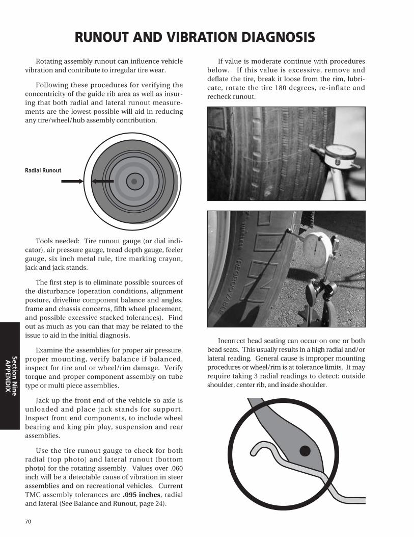
Rotating assembly runout can influence vehiclevibration and contribute to irregular tire wear.
Following these procedures for verifying theconcentricity of the guide rib area as well as insur-ing that both radial and lateral runout measure-ments are the lowest possible will aid in reducingany tire/wheel/hub assembly contribution.
Tools needed: Tire runout gauge (or dial indi-cator), air pressure gauge, tread depth gauge, feelergauge, six inch metal rule, tire marking crayon,jack and jack stands.
The first step is to eliminate possible sources ofthe disturbance (operation conditions, alignmentposture, driveline component balance and angles,frame and chassis concerns, fifth wheel placement,and possible excessive stacked tolerances). Findout as much as you can that may be related to theissue to aid in the initial diagnosis.
Examine the assemblies for proper air pressure,proper mounting, verify balance if balanced,inspect for tire and or wheel/rim damage. Verifytorque and proper component assembly on tubetype or multi piece assemblies.
Jack up the front end of the vehicle so axle isunloaded and place jack stands for support.Inspect front end components, to include wheelbearing and king pin play, suspension and rearassemblies.
Use the tire runout gauge to check for bothradial (top photo) and lateral runout (bottomphoto) for the rotating assembly. Values over .060inch will be a detectable cause of vibration in steerassemblies and on recreational vehicles. CurrentTMC assembly tolerances are .095 inches, radialand lateral (See Balance and Runout, page 24).
If value is moderate continue with proceduresbelow. If this value is excessive, remove anddeflate the tire, break it loose from the rim, lubri-cate, rotate the tire 180 degrees, re-inflate andrecheck runout.
Incorrect bead seating can occur on one or bothbead seats. This usually results in a high radial and/orlateral reading. General cause is improper mountingprocedures or wheel/rim is at tolerance limits. It mayrequire taking 3 radial readings to detect: outsideshoulder, center rib, and inside shoulder.
RUNOUT AND VIBRATION DIAGNOSIS
70
Section
Nin
eA
PPEND
IX
Radial Runout

Note: The bead seating surface of the tire andwheel do not match up as shown in previous photo.This incorrect seating is the result mismount. TheTMC specification is 2/32nds (.062 inch). If bothwheel and tire are lubricated and initial air inflationis done with the tire flat, you should have 1/32nd orless variance around the tire.
Check for this mismount condition with the sixinch ruler, measuring is 4 locations around anunladen assembly.
Check for hub to wheel clearance on hub pilot-ed assemblies with the feeler gauge. If you deter-mine that the measured high spot lines up with thefeeler gauge gap, rotate the assembly so the gap isat the top, loosen the lug nuts, and allow gravity tocenter the wheel on the hub. Hand tighten the topnut, then tighten all nuts in the proper sequenceand recheck for runout.
On cast spoke and demountable rim assem-blies, loosen and properly retighten the rim clampnuts to the proper torque. Recheck for runout.
Verification of radial (top photo) and lateral(bottom photo) wheel runout is another step to beconsidered. TMC tolerances are .070 inch ontubeless steel disc wheels and .030 inch on tubelessaluminum disc wheels.
71
Sect
ion
Nin
eA
PPEN
DIX

Tools required: Metric Tape, Jack Stand, Toe-Scribe, 2 Cans of White Spray Paint, 2 Heavy PlasticBags, Vehicle Jack (10 Ton), Flashlight, WheelChocks, Tire Iron.
Refer to Michelin Video, ATTACC Plus(MWV41200) for reference.
Install wheel chocks on the rear tires and jack upthe right front tire and place jack stand under axle.
(Note: conduct the following procedures on theright front tire position, then do the same on theleft front tire position.)
Rotate the front tire to inspect for proper brakeadjustment, brake drum grab, bearing noise, lateralrunout, and obvious dynamic tire imbalance. Alsolook at the tire guide rib area in relation to the rimflange. If a notable difference in the distancebetween both is spotted, pay close attention to theradial runout when you scribe your circumferentialtoe measuring line later in this procedure.
Insert Tire Iron into the wheel assembly at the6 o’clock position and place your other hand atthe 12 o’clock position. With a rocking typemotion try to move the tire assembly up with thelower bar and out towards you with your lefthand. If play is felt it is probably the result ofloose wheel bearings or worn king pin bushings. Ifyou observe the brake chamber moving, it can beisolated to the king pin bushing. If it does notmove, it is likely the wheel bearings.
With your hands placed at the 3 o’clock and atthe 9 o’clock position on the tire, try to move thetire in a rapid "left turn – right turn" type of motion.Feel and listen for any play. Play in this area wouldindicate either loose or worn tie rod ends, steeringarms, drag link ends, or steering box play. Any playin this area should be further inspected to insure itis within the vehicle and/or part manufacturesspecifications.
Two additional parts that can cause tire wearneed to be checked. First, see if the brake drum has
a balance weight and second, look for wear on thespring shackle assembly. This check is more diffi-cult to make and there are various ways to inspectfor this wear. Consult the part manufacture for theproper way to inspect.
On a dry tire, with a can of spray paint, markeror chalk (dusting with any coating material suitablefor marking a section of tread), "highlight" a sec-tion of the tread area around the tire. With a sharppointed scribe, mark a thin line in the "highlighted"area while rotating the tire. (Note: at this pointobserve the amount of radial runout by referencingthis line to the rotating tire. Any runout greaterthan 3/32nd" should be further investigated forimproper tire bead seating, improper tire/wheelrunout and/or improper wheel torque procedureduring installation.)
Next, lower the vehicle and drive it forward,stopping in gear (without braking), or lower thevehicle onto a frictionless surface. (Note: Properlycleaned turn plates offer the best frictionless sur-face. Reasonable success can be obtained usingclean and lubricated slide plates, or, by using a 3 to4 mil plastic sheet folded over itself 3 to 4 times ona smooth shop floor.) Prior to measuring, youshould "joust" the vehicle by standing on the step,and with your body weight shake the unit. This willfurther relax the front suspension giving you a cor-rect toe reading.
Once the steer tires are down, mark a point onthe front and rear of the each tire using the paintcans as a reference to measuring an equal heightfrom the floor that is perpendicular to your scribeline. Measure from side to side with a tape meas-ure or a fine lined toe gauge. The difference inmeasurement across the front versus the rear of thetire is your toe. If it is a larger difference in thefront it is toe out, if it is larger in the rear, it is toe in.
Recommended Toe setting is +1/16" (1.5mm)
72
TOE MEASUREMENT – FIELD METHOD
Section
Nin
eA
PPEND
IX

EFFECT CAUSE
73
TIRE DAMAGE – EFFECT AND CAUSE
Sect
ion
Nin
eA
PPEN
DIX
All scrap tire failures are cause and effect relat-ed. In the majority of the situations, it is the effectthat we first see when we look at the tire damage.However, tire condition “effects” may have manycauses. Often a pattern can be found that may
point to changes needed to avoid future scrap fail-ures of this nature. Surprisingly, the majority oftubeless commercial scrap conditions are found inthe following 6 damage categories:
• Crown / sidewall injury resulting in air loss
(nail hole/bolt/debris penetrating the liner)
• Leaking valve, grommet or wheel/rim
• Improper repair or improper repair procedures
(premature failure of repair)
• Bead damage due to mount/dismount
• Nail (bolt, screw, etc.) or any object that penetrates
into the tire and through the inner liner
• Improper repair or improper repair procedures
(premature failure of repair)
• Radial liner split (due to impact)
• Bead area or inner liner damage
(result of poor mounting procedures)
• Inner liner cut (shipping or mounting damage)
• Inner liner burn (e.g. electrical discharge damage)
• Impact with a curb, pothole, road debris, etc.
• Severe impact with any blunt object
• Impact with a sharp cutting object. (A rupture
usually indicates a rather severe impact.)
• Run flat tires (mainly dual positions)
• Impacts to steel (not filled or repaired)
• Improper repair or improper repair procedures
(premature failure of repair)
• This may be a final removal condition on an old
or well used tire
• Heavy brake heat generating operations
• Mechanical brake system out of specification
• Incorrect wheel width
• Excessive flex from overload/underinflation
• Mounting/Dismounting (insufficient lubrication, improper
tool use, aggravated by heat (beads become brittle))
• Operational (spread axles, any high lateral scrub operation)
RUN FLATRun flat is defined as any tire operating at less
than 80% of the recommended air pressure for
the load being carried
AIR INFILTRATIONAny damage which opens the inner liner and
allows air under pressure, to migrate within the
steel and rubber products
PINCH SHOCKCrown/sidewall impact compressing the tire
until the internal rubber products hit
IMPACT DAMAGE• With or without a rupture - zipper
• Crown, shoulder, or sidewall
FATIGUE RELATED DAMAGE• With or without a rupture - zipper
• Any damage which will allow the casing
to oxidize or the casing plies to weaken
or break
BEAD DAMAGESBead turning, cracking/splitting, unwrapping
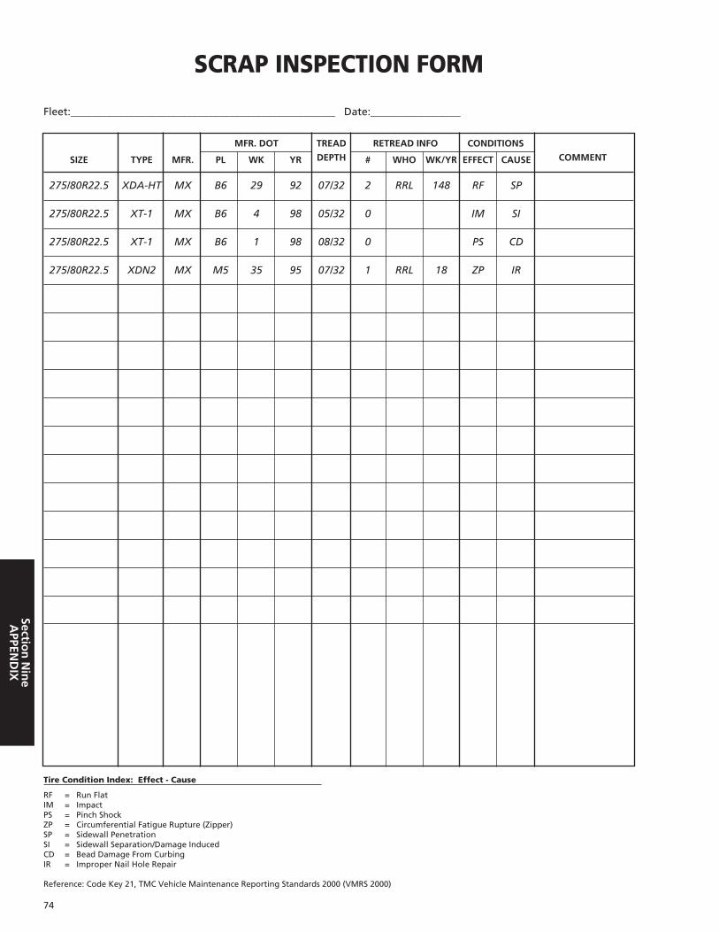
74
Section
Nin
eA
PPEND
IX
MFR. DOT TREAD RETREAD INFO CONDITIONS
SIZE TYPE MFR. PL WK YR DEPTH # WHO WK/YR EFFECT CAUSE COMMENT
275/80R22.5 XDA-HT MX B6 29 92 07/32 2 RRL 148 RF SP
275/80R22.5 XT-1 MX B6 4 98 05/32 0 IM SI
275/80R22.5 XT-1 MX B6 1 98 08/32 0 PS CD
275/80R22.5 XDN2 MX M5 35 95 07/32 1 RRL 18 ZP IR
275/80R22.5 XDHT MX B6 29 92 07/32 2 RRL 148 FF SW
SCRAP INSPECTION FORM
Fleet:__________________________________________________ Date:_________________
RF = Run FlatIM = ImpactPS = Pinch ShockZP = Circumferential Fatigue Rupture (Zipper)SP = Sidewall PenetrationSI = Sidewall Separation/Damage InducedCD = Bead Damage From CurbingIR = Improper Nail Hole Repair
Reference: Code Key 21, TMC Vehicle Maintenance Reporting Standards 2000 (VMRS 2000)
Tire Condition Index: Effect - Cause

75
IND
EX
AAckerman Principle . . . . . . . . . . . . . 29AIRSTOP Tube. . . . . . . . . . . . . . . . . . 52Alignment. . . . . . . . . . . . . . . . . . . . . 27Alignment Checks (Frequency) . . . . . 30Alignment Equipment . . . . . . . . . . . 30Alignment Targets (TMC Guidelines) . . 29Ambient Temperature . . . . . . . . . . . . 8Application
Long Haul . . . . . . . . . . . . . . . . . . . . 4Regional . . . . . . . . . . . . . . . . . . . . . 4On/Off Road . . . . . . . . . . . . . . . . . . 4Urban . . . . . . . . . . . . . . . . . . . . . . . 5Commercial Light Truck. . . . . . . . . 5Industrial. . . . . . . . . . . . . . . . . . . . . 5 Special Application Tires . . . . . . . . 5Small Earthmover Tires . . . . . . . . . 5
Aspect Ratio . . . . . . . . . . . . . . . . . 6, 52Axle Parallelism and Tracking . 30 - 31ATTACC Plus System . . . . . . . . . 60 - 61
BBalance . . . . . . . . . . . . . . . . . . . . . . . 24Bias-Ply (Cross Ply) . . . . . . . . . . . . . . 52 Bib Alignment System . . . . . . . . . . . 30Braking Systems and issues . . . . . . . 33Buff Radius . . . . . . . . . . . . . . . . . . . . 47Buff Width . . . . . . . . . . . . . . . . . . . . 49
CCamber . . . . . . . . . . . . . . . . . . . . . . . 28Casing Management. . . . . . . . . 62 - 63Caster . . . . . . . . . . . . . . . . . . . . . . . . 28Central Tire Inflation System. . . . . . 22Chains . . . . . . . . . . . . . . . . . . . . . . . . 25Clearances . . . . . . . . . . . . . . . . . 15 - 17
Lateral Clearances . . . . . . . . . . . . 15Vertical Clearances. . . . . . . . . . . . 16Longitudinal Clearances . . . . . . . 16Front Wheel Clearances. . . . . . . . 17
Cold Climate Pressure . . . . . . . . . . . 64Conversion Table . . . . . . . . . . . . . . . 65Cost Analysis . . . . . . . . . . . . . . . 50 - 51Cost Per Mile (CPM) . . . . . . . . . . . . . 50Critical Six Fundamentals. . . . . . . . . 65
DDamages (Radial/Crown) . . . . . . . . . 42Disc Wheel Installation . . . . . . . 66 - 67DOT Sidewall Markings . . . . . . . . . . 66Dual Assembly . . . . . . . . . . . . . . . . . 19Dual Spacing/Measuring. . . . . . 19 - 20Dynamometers . . . . . . . . . . . . . . . . 25
EEquivalent Sizes . . . . . . . . . . . . . . . . 10
FFifth Wheel . . . . . . . . . . . . . . . . . . . . 34Flap Code . . . . . . . . . . . . . . . . . . . . . 52Free Radius . . . . . . . . . . . . . . . . . . . . . 6Fuel Efficiency/Saving/Analysis . . 1, 51Fuel Analysis . . . . . . . . . . . . . . . . . . . 51
GGCW (Gross Combination Weight) . . . . 12Gear Ratio. . . . . . . . . . . . . . . . . . 15, 39GVW (Gross Vehicle Weight) . . . . . . . . 12GAWR (Gross Axle Weight Rating) . . . . 12
HHub Piloted Disc Wheel . . . . . . 67 - 68
IInflation Pressure . . . . . . . 8, 21, 22, 64
LLoad Index . . . . . . . . . . . . . . . . . . . . 59Load per Inch Width Law. . . . . . . . . 23Load Range/Ply Rating. . . . . . . . . . . 57Loaded Radius . . . . . . . . . . . . . . . . . . 6Loads Per Axle . . . . . . . . . . . . . . . . . . 8Low-Profile Truck Tire . . . . . . . . . . . 10Lubrication . . . . . . . . . . . . . . . . 14, 54
MMaintaining the Tire. . . . . . . . . 21 - 26Maintaining the Vehicle . . . . . . 27 - 34Mounting The Tire . . . . . . . . . . 13 - 20
Tubeless . . . . . . . . . . . . . . . . . 13 - 18Tube-Type . . . . . . . . . . . . . . . 54 - 56X One . . . . . . . . . . . . . . . . . . . . . . 38
NNominal Wheel Diameter . . . . . . . . . 6
OOffset - Dual and Front Wheels. . . . 15Overall Diameter/Width . . . . . . . . . . 6Overinflation . . . . . . . . . . . . . . . . . . 22
PPressure Coefficients . . . . . . . . . . . . . 9Pressure Monitoring System . . . . . . 22Pressure Unit Conversion Table. . . . 57Puncture Repair . . . . . . . . . . . . 44 - 46
RRecreational Vehicles . . . . . . . . . . . . 22Regrooving . . . . . . . . . . . . . . . . . . . . 10Repairs . . . . . . . . . . . . . . . . . . . . 41 - 43Repair Limit . . . . . . . . . . . . . . . . 42 - 43Retreading. . . . . . . . . . . . . . . . . 47 - 49Revolutions Per Mile . . . . . . . . . . . . . 6Rims. . . . . . . . . . . . . . . . . . . . . . . . . 6, 8Rim Width. . . . . . . . . . . . . . . . . . . . . 15RPM Calculation . . . . . . . . . . . . . . . . 69Rotation . . . . . . . . . . . . . . . . . . . . . . 26Runout. . . . . . . . . . . . . . 20, 24, 70 - 71
SSafety Device/Cage. . . . . . . . 18, 39, 56Scrap Inspection Form . . . . . . . . . . . 74Section Height . . . . . . . . . . . . . . . . . . 6Siping . . . . . . . . . . . . . . . . . . . . . . . . 10Speed Restrictions . . . . . . . . . . . . . . . 8Speed Symbol . . . . . . . . . . . . . . . . . . 57Spinning . . . . . . . . . . . . . . . . . . . . . . 26Specification Data Table . . . . . . . . . . 7Static and Low Speed Load . . . . . . . . 9Steer Axle Geometry . . . . . . . . . . . . 27Steer Axle Setback (Skew). . . . . . . . . 28Storage . . . . . . . . . . . . . . . . . . . . . . . 25Stud Piloted Disc Wheel . . . . . . 67 - 68Suspensions . . . . . . . . . . . . . . . . . . . 34Suspension Fault . . . . . . . . . . . . 35 - 36
TTandem Axle Parallelism . . . . . . . . . 29Tandem Axles . . . . . . . . . . . . . . . . . . 20Thrust Angle. . . . . . . . . . . . . . . . . . . 29Tire Damage . . . . . . . . . . . . . . . . . . . 73Tire Deflection . . . . . . . . . . . . . . . . . . 6Tire Inspection . . . . . . . . . . . . . . . . . 22Tire Mixing . . . . . . . . . . . . . . . . . . . . 20Tire Size Marking . . . . . . . . . . . . 10, 53Tire Wear. . . . . . . . . . . . . . . . . . 32 - 33
Toe Wear . . . . . . . . . . . . . . . . . . . 32Camber Wear . . . . . . . . . . . . . . . . 32Free Rolling Wear . . . . . . . . . . . . 32Cupping Wear . . . . . . . . . . . . . . . 32Flat Spotting Wear. . . . . . . . . . . . 32Diagonal Wear . . . . . . . . . . . . . . . 33
Toe . . . . . . . . . . . . . . . . . . . . . . . . . . 27Toe-Out-On-Turns . . . . . . . . . . . . . . 29Torque . . . . . . . . . . . . . . . . . . . . 18, 68Tread Depth Measurements . . . . . . 23Troubleshooting . . . . . . . . . . . . 35 - 36Tube Code . . . . . . . . . . . . . . . . . . . . 52Tubeless Tire . . . . . . . . 13 -20, 37 - 40Tube-Type Tire . . . . . . . . . . . . . 52 - 56
UUnderinflation . . . . . . . . . . . . . . . . . 22Undertread . . . . . . . . . . . . . . . . . . . . 48Units of Measurement . . . . . . . . . . . 57
VVehicle Alignment . . . . 27 - 31, 60 - 61Vibration Diagnosis. . . . . . . . . . 70 - 71
WWear Bar. . . . . . . . . . . . . . . . . . . . . . 23Weight Class . . . . . . . . . . . . . . . 11 - 12
XX One. . . . . . . . . . . . . . . . . . . . . 37 - 40
INDEX


77

MICHELIN NORTH AMERICA, INC., Greenville, South Carolina, USAMICHELIN NORTH AMERICA (CANADA) INC., Laval, Quebec, CanadaMICHELIN MEXICO S.A. DE C.V., Mexico City, Mexico
An Equal Opportunity Employer
© 2005 MNA (1/05)
MWL40732
Michelin® Truck Tire Service Manual
To learn more please contact your Michelin Sales Representative or visit
www.michelintruck.com
To order more books, please call Promotional Fulfillment Center
1-800-677-3322, Option #2Monday through Friday, 9 a.m. to 6 p.m. Eastern Time