pds type-2 stepper drive user guide - · pdf filepds type 2 stepper drive user guide (pds13-2...
TRANSCRIPT

PDS Type 2 Stepper DriveUser Guide
(PDS13-2 PDS15-2 PDS15-D-2)
For engineering For engineering For engineeringassistance in Europe: assistance in Germany assistance in the U.S.:Parker Hannifin plc Parker Hannifin GmbH Parker Hannifin CorporationElectromechanical Electromechanical Compumotor DivisionDivision - Digiplan Division - Hauser 5500 Business Park Drive, Suite D21 Balena Close P. O. Box: 77607-1720 Rohnert Park CA 94928 USAPoole, Dorset Robert-Bosch-Str. 22 Tel: (800) 358-9070England, BH17 7DX D-77656 Offenburg Germany Fax: (707) 584-3793Tel: 01202-699000 Tel: (0781) 509-0 FaxBack System: (800) 936-6939Fax: 01202-695750 Fax: (0781) 509-176 BBS: (707) 584-4059E-mail: [email protected] E-mail: [email protected]
Part No: 1600. 171.05 February, 1998

IMPORTANT INFORMATION FOR USERS
Installation and Operation of Digiplan Equipment
It is important that Digiplan motion control equipment is installed and operated in such a way that all applicablesafety requirements are met. Note that it may be necessary for the complete installation to comply with the LowVoltage or Machinery Directives. It is your responsibility as an installer to ensure that you identify the relevantsafety standards and comply with them; failure to do so may result in damage to equipment and personal injury.In particular, you should study the contents of this user guide carefully before installing or operating theequipment.
The installation, set-up, test and maintenance procedures given in this User Guide should only be carried out bycompetent personnel trained in the installation of electronic equipment. Such personnel should be aware ofthe potential electrical and mechanical hazards associated with mains-powered motion control equipment -please see the safety warning below. The individual or group having overall responsibility for this equipmentmust ensure that operators are adequately trained.
Under no circumstances will the suppliers of the equipment be liable for any incidental, consequential or specialdamages of any kind whatsoever, including but not limited to lost profits arising from or in any way connectedwith the use of the equipment or this user guide.
! SAFETY WARNING
High-performance motion control equipment is capable of producing rapid movement and very high forces.Unexpected motion may occur especially during the development of controller programs. KEEP WELLCLEAR of any machinery driven by stepper or servo motors. Never touch it while it is in operation.
This product is sold as a motion control component to be installed in a complete system using good engineeringpractice. Care must be taken to ensure that the product is installed and used in a safe manner according to localsafety laws and regulations. In particular, the product must be enclosed such that no part is accessible whilepower may be applied.
High voltages exist within enclosed units, on rack system backplanes (motherboards) and on transformerterminals. Operators must be denied access to these areas. Service personnel must keep clear of these areaswhen power is applied to the equipment.
If the equipment is used in any manner that does not conform to the instructions given in this user guide, thenthe protection provided by the equipment may be impaired.
The information in this user guide, including any apparatus, methods, techniques, and concepts describedherein, are the proprietary property of Parker Digiplan or its licensors, and may not be copied, disclosed, or usedfor any purpose not expressly authorised by the owner thereof.
Since Digiplan constantly strives to improve all of its products, we reserve the right to modify equipment anduser guides without prior notice. No part of this user guide may be reproduced in any form without the priorconsent of Digiplan.
© Digiplan Division of Parker Hannifin plc, 1998– All Rights Reserved –

Product Type: PDS13-2, PDS15-2, PDS15-D-2
The above products are in compliance with the requirements of the followingDirectives, when installed in accordance with the instructions containedwithin this User Guide.
• 73/23/EEC Low Voltage Directive
• 93/68/EEC CE Marking Directive
The PDS Series of drives are sold as complex components to professional assemblers, ascomponents they are not compliant with Electromagnetic Compatibility Directive89/336/EEC. However, information is offered in this User Guide on how to install thesedrives in a manner most likely to minimise the effects of drive emissions and to maximisethe immunity of drives from externally generated interference.

CONTENTS i
Contents
Contents............................................................................................................iSection 1. INTRODUCTION ..............................................................................1Section 2. SPECIFICATION..............................................................................3Section 3. INSTALLATION ..............................................................................7Section 4. Setting Up....................................................................................3 1Section 5. Maintenance & Troubleshooting ...................................................3 5Index ..............................................................................................................3 9
User Guide Change SummaryThe following is a summary of the primary changes to this user guide since the last versionwas released. This user guide, version 1600.171.05, supersedes version 1600.171.04.
When a user guide is updated, the new or changed text is differentiated with a change barin the outside margin (this paragraph is an example). If an entire section is changed, thechange bar is located on the outside margin of the section title.
Major changes introduced at revision 05 are:
Clarification of motor wiring requirements
Corrections to the drive mounting hole dimensions (Figure 3-12)
Factory default setting of bit switch 3 has been changed to OFF
Warning symbols used on the PDS series of drives have the following meanings:
Refer to theaccompanying documentation
Risk of electric shock
Hot surface
Protective conductor terminal
Alternating current
Frame or chassis terminal

ii PDS SERIES DRIVE USER GUIDE

SECTION 1. INTRODUCTION 1
Section 1. INTRODUCTION
Product DescriptionThe PDS series of single-axis packaged ministep drives consists of the PDS13-2 &PDS15-2, with peak current ratings of 3A and 5A respectively. A further 5A version, knownas the PDS15-D-2 is also available with a built-in regenerative dump circuit. PDS seriesdrives are high-performance, MOSFET, chopper-regulated stepper drives designed foroptimum performance in low and medium power applications. A recirculating chopperregulator improves operating efficiency, minimizes power consumption, and reduces motorand drive heating. They are powered Direct On-Line (DOL) from mains supplies of 110V to240V (nominal) AC. An internal switch mode power supply is used, incorporating PowerFactor Correction (PFC) to minimise distortion of the AC supply.
The PDS series of drives have 4 selectable resolutions between 400 steps/rev and 4000steps/rev, set using the front panel switches.
Motor short-circuit protection is assured across and between phases and between anyphase and earth. If a wiring fault occurs the drive fault LED will be lit up - seeMaintenance and Troubleshooting.
The drives are suitable for use with hybrid and permanent magnet stepping motors having4, 6, or 8 leads.
The drives can be used as stand alone units with separate control inputs and motorconnection/power inputs. An on-board clock can be used to control drive motion or anexternal step direction source can be used.
The step, direction and shutdown differential inputs are fully opto isolated for maximumnoise immunity. The type 2 series of drives have improved input noise immunity comparedwith the PDS13 and PDS15/PDS15-D series. These noise immunity improvements mayrequire minor connection changes (detailed in the Installation section) to make a type 2drive a plug-in replacement for an existing PDS13 or PDS15/PDS15-D drive.

2 PDS SERIES DRIVE USER GUIDE
The system may be configured to allow the clock signal to be provided by the drive'sinternal clock source. Two separate programmable speeds are available. These are set byfront panel pots marked “Fast” and “Slow”, a third pot allows adjustment of the accelerationand deceleration times. The speed control potentiometers may be mounted remotely viathe front panel D-type connector.
The internal clock source signal is brought out to the drive control connector for monitoringpurposes.
The drive and integral power supply are contained in one compact enclosure, cooled bynatural convection. Wall or panel vertical mounting is recommended to allow access to thefront panel connectors and controls for service personnel use only.
SECTION 2. SPECIFICATION 3
Section 2. SPECIFICATION
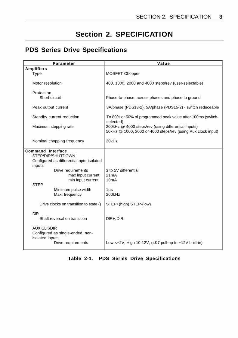
PDS Series Drive Specifications
Parameter ValueAmplifiers
Type
Motor resolution
ProtectionShort circuit
Peak output current
Standby current reduction
Maximum stepping rate
Nominal chopping frequency
MOSFET Chopper
400, 1000, 2000 and 4000 steps/rev (user-selectable)
Phase-to-phase, across phases and phase to ground
3A/phase (PDS13-2), 5A/phase (PDS15-2) - switch reduceable
To 80% or 50% of programmed peak value after 100ms (switch-selected)200kHz @ 4000 steps/rev (using differential inputs)50kHz @ 1000, 2000 or 4000 steps/rev (using Aux clock input)
20kHz
Command InterfaceSTEP/DIR/SHUTDOWNConfigured as differential opto-isolatedinputs
Drive requirementsmax input currentmin input current
STEPMinimum pulse widthMax. frequency
Drive clocks on transition to state ()
DIRShaft reversal on transition
AUX CLK/DIRConfigured as single-ended, non-isolated inputs
Drive requirements
3 to 5V differential21mA10mA
1µs200kHz
STEP+(high) STEP-(low)
DIR+, DIR-
Low <+2V, High 10-12V, (4K7 pull-up to +12V built-in)
Table 2-1. PDS Series Drive Specifications
4 PDS SERIES DRIVE USER GUIDE
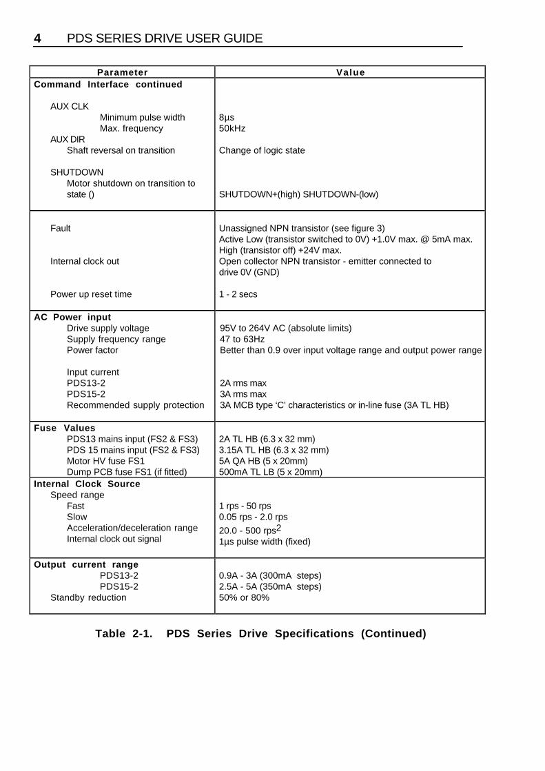
Parameter ValueCommand Interface continued
AUX CLKMinimum pulse widthMax. frequency
AUX DIRShaft reversal on transition
SHUTDOWNMotor shutdown on transition to state ()
8µs50kHz
Change of logic state
SHUTDOWN+(high) SHUTDOWN-(low)
Fault
Internal clock out
Power up reset time
Unassigned NPN transistor (see figure 3)Active Low (transistor switched to 0V) +1.0V max. @ 5mA max.High (transistor off) +24V max.Open collector NPN transistor - emitter connected todrive 0V (GND)
1 - 2 secs
AC Power inputDrive supply voltageSupply frequency rangePower factor
Input currentPDS13-2PDS15-2Recommended supply protection
95V to 264V AC (absolute limits)47 to 63HzBetter than 0.9 over input voltage range and output power range
2A rms max3A rms max3A MCB type ‘C’ characteristics or in-line fuse (3A TL HB)
Fuse ValuesPDS13 mains input (FS2 & FS3)PDS 15 mains input (FS2 & FS3)Motor HV fuse FS1Dump PCB fuse FS1 (if fitted)
2A TL HB (6.3 x 32 mm)3.15A TL HB (6.3 x 32 mm)5A QA HB (5 x 20mm)500mA TL LB (5 x 20mm)
Internal Clock SourceSpeed range
FastSlowAcceleration/deceleration rangeInternal clock out signal
1 rps - 50 rps0.05 rps - 2.0 rps
20.0 - 500 rps2
1µs pulse width (fixed)
Output current rangePDS13-2PDS15-2
Standby reduction
0.9A - 3A (300mA steps)2.5A - 5A (350mA steps)50% or 80%
Table 2-1. PDS Series Drive Specifications (Continued)
SECTION 2. SPECIFICATION 5
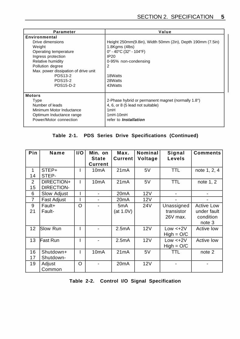
Parameter ValueEnvironmental
Drive dimensionsWeightOperating temperatureIngress protectionRelative humidityPollution degreeMax. power dissipation of drive unit
PDS13-2PDS15-2PDS15-D-2
Height 250mm(9.8in), Width 50mm (2in), Depth 190mm (7.5in)1.8Kgms (4lbs)0° - 40°C (32° - 104°F)IP200-95% non-condensing2
18Watts28Watts43Watts
MotorsTypeNumber of leadsMinimum Motor InductanceOptimum Inductance rangePower/Motor connection
2-Phase hybrid or permanent magnet (normally 1.8°)4, 6, or 8 (5 lead not suitable)1mH1mH-10mHrefer to Installation
Table 2-1. PDS Series Drive Specifications (Continued)
Pin Name I/O Min. onState
Current
Max.Current
NominalVoltage
SignalLevels
Comments
114
STEP+STEP-
I 10mA 21mA 5V TTL note 1, 2, 4
215
DIRECTION+DIRECTION-
I 10mA 21mA 5V TTL note 1, 2
6 Slow Adjust I - 20mA 12V - -7 Fast Adjust I - 20mA 12V - -9
21Fault+Fault-
O - 5mA(at 1.0V)
24V Unassignedtransistor26V max.
Active Lowunder faultcondition
note 312 Slow Run I - 2.5mA 12V Low <+2V
High = O/CActive low
13 Fast Run I - 2.5mA 12V Low <+2VHigh = O/C
Active low
1617
Shutdown+Shutdown-
I 10mA 21mA 5V TTL note 2
19 AdjustCommon
O - 20mA 12V - -
Table 2-2. Control I/O Signal Specification

6 PDS SERIES DRIVE USER GUIDE
Pin Name I/O Min. onState
Current
Max.Current
NominalVoltage
SignalLevels
Comments
20 Internal clockout
O - 15mA 24V Open collectorLow <250mV
@ Ic 10mA
Active low
23 Aux Clock In I - 2.5mA 12V Low <+2VHigh = O/C
Active lownote 2, 5
24 Aux Direction In I - 2.5mA 12V Low <+2VHigh = O/C
note 2, 6
25 GND I/O - - - - Signalreturn
Table 2-2. Control I/O Signal Specification (Continued)
note 1 Do not change state of ‘DIRECTION+’ and ‘DIRECTION-’ inputs within 2.5µs ofSTEP transition to STEP+ high, STEP- low.
note 2 See Figure 10 for input circuit.note 3 See Figure 7 for output circuit.note 4 Mininum pulse width 1µs, maximum frequency 200kHz.note 5 Mininum pulse width 8µs, maximum frequency 50kHz.note 6 Do not change the state of ‘AUX DIRECTION’ within 8µs of ‘AUX CLOCK’
transition from high to low.

SECTION 3. INSTALLATION 7
Section 3. INSTALLATION
Installation OptionsPDS drives must be installed by competent personnel familiar with the installation,commissioning and operation of motion control equipment. In the final application theequipment must be enclosed to prevent the operator coming into contact with any highvoltages. This includes the drive and motor terminations.
The drives are not EMC compliant, they are sold as a complex component for professionalassemblers of motion control systems. Where a system is not required to conform to theEuropean EMC directive the installation procedure described in this Section may befollowed. Systems which are to conform to the European EMC directive should beassembled using these procedures and additionally the EMC specific installationrecommendations, described at the end of this Section. Digiplan cannot guarantee EMCcompliance.
The drive must be installed in an enclosure to protect it from atmospheric contaminantssuch as oil, moisture, dirt, etc. No operator access should be allowed to the drive while ithas AC power applied. Metal equipment cabinets are ideally suited for siting theequipment since they can provide operator protection, EMC screening and can be fittedwith interlocks arranged to remove all AC power when the cabinet door is open.
Provision must be made within the installation to contain the spread of fire by the fitting of aflame barrier, as defined in the LVD enclosure requirements. In many applications thisrequirement will be met simply by installing the drive within a cabinet fitted with a solidmetal base. If the cabinet base is ventilated a flame barrier will be required that conformswith the baffle dimensions defined in the European Standard EN 61010-1.
Power ConnectionsInput power is taken directly from AC supplies via the front panel mounted IEC 3-way mainsinlet socket. A power cord is supplied with the drive. Ensure that the drive is reliablyearthed. Any mains wiring should have an insulation rating of at least 1350V (useapproved mains cable of at least 0.75mm2 CSA), and should be kept separate from themotor and signal wiring.
Wiring GuidelinesProper grounding of electrical equipment is essential to ensure the safety of personnel andto reduce the effects of electrical noise due to electromagnetic interference (EMI). AllDigiplan equipment should be properly grounded.
In general, all components and enclosures must be connected to earth ground to provide alow impedance path for ground fault or noise-induced currents. All earth groundconnections must be continuous and permanent. A central earth stud is recommended.

PDS SERIES DRIVE USER GUIDE8
Motor SelectionUsually optimum performance will be obtained when the current rating of the motor isbetween 1 and 1.5 times the drive rating (refer to specification).
For maximum high speed torque a motor rating of 7.5A peak should be used with thePDS15-2, 4.5A with the PDS13-2. The drives can be derated to accommodate motors withlower current ratings however, the high speed torque will be reduced.Do not use a drive setting which gives an output current greater than the motor rating.With 4 lead motors the bipolar rating is quoted and this should match the criteria statedabove.With 6 lead motors the unipolar rating is quoted, but for best performance with the PDSDrives the centre tap of each winding should be left unconnected and the connectionsmade between the winding ends. This will give a bipolar rating 70% of the quoted motorunipolar rating.With 8 lead motors the bipolar rating of the motor, which is normally quoted refers to aparallel winding connection. With the windings connected in series the current rating of themotor connection will be 50% that of the bipolar rating, and the motor will give improvedlow-speed torque, but reduced high-speed torque.
Regenerative Power Dump OptionApplications which involve rapid deceleration of high-inertia loads may require that thedrive is fitted with a power dissipation circuit. The PDS15-D-2 has the same electricalspecification as the PDS15-2 but incorporates a power dump with a continuous rating of 15watts (170 watts peak). You will need the PDS15-D-2 in the following situation:
Metric formula - if the deceleration time t<Jω2 - 0.1where t is the deceleration time in secondsJ is the total system inertia in Kg-m2
ω is the maximum speed in revolutions per second
Imperial formula - if the deceleration time t<0.02Jω2 - 100where t is the deceleration time in millisecondsJ is the total system inertia in oz-in2
ω is the maximum speed in revolutions per second
If the expression in brackets is negative, the power dump option is not required. This optionis strongly recommended for size 42 (106) motors.
Note that a program to calculate if a power dump is required is available from Compumotorand Digiplan Technical Support departments (Windows 3.1 required). This program is alsoavailable on Compumotor’s Bulletin Board Service (see front cover for number).
Long Motor LeadsUsing a motor with long leads will cause the cabling resistance to become significant whencompared to the resistance of the motor.
SECTION 3. INSTALLATION 9
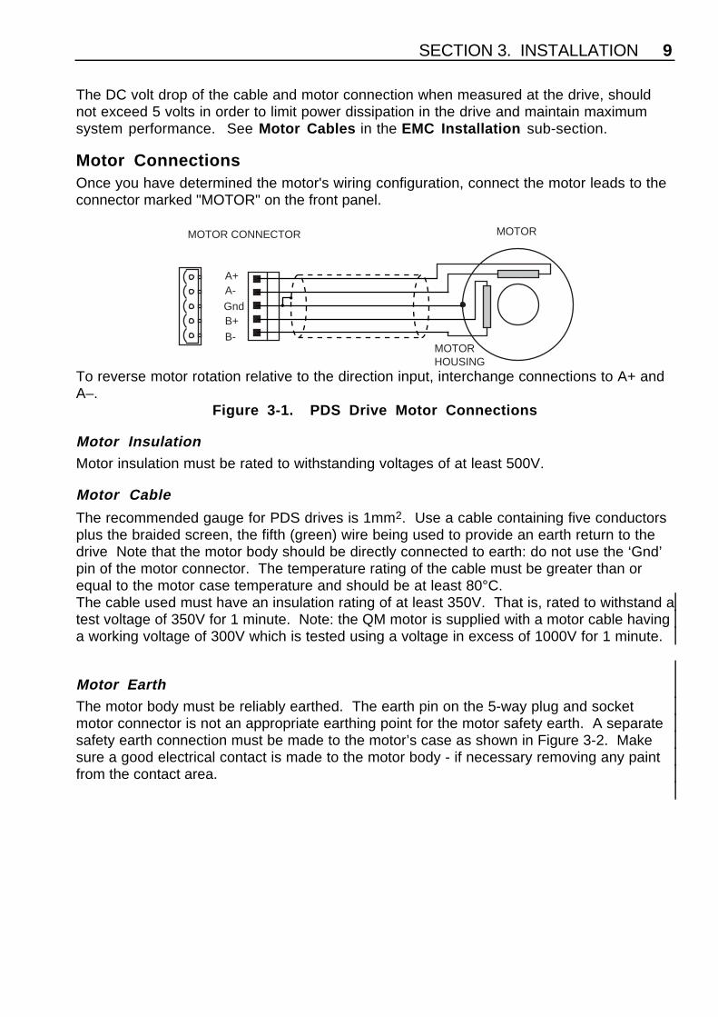
The DC volt drop of the cable and motor connection when measured at the drive, shouldnot exceed 5 volts in order to limit power dissipation in the drive and maintain maximumsystem performance. See Motor Cables in the EMC Installation sub-section.
Motor ConnectionsOnce you have determined the motor's wiring configuration, connect the motor leads to theconnector marked "MOTOR" on the front panel.
MOTOR CONNECTOR
A+A-GndB+B-
MOTORHOUSING
MOTOR
To reverse motor rotation relative to the direction input, interchange connections to A+ andA–.
Figure 3-1. PDS Drive Motor Connections
Motor InsulationMotor insulation must be rated to withstanding voltages of at least 500V.
Motor Cable
The recommended gauge for PDS drives is 1mm2. Use a cable containing five conductorsplus the braided screen, the fifth (green) wire being used to provide an earth return to thedrive Note that the motor body should be directly connected to earth: do not use the ‘Gnd’pin of the motor connector. The temperature rating of the cable must be greater than orequal to the motor case temperature and should be at least 80°C.The cable used must have an insulation rating of at least 350V. That is, rated to withstand atest voltage of 350V for 1 minute. Note: the QM motor is supplied with a motor cable havinga working voltage of 300V which is tested using a voltage in excess of 1000V for 1 minute.
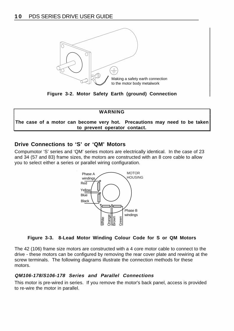
Motor EarthThe motor body must be reliably earthed. The earth pin on the 5-way plug and socketmotor connector is not an appropriate earthing point for the motor safety earth. A separatesafety earth connection must be made to the motor’s case as shown in Figure 3-2. Makesure a good electrical contact is made to the motor body - if necessary removing any paintfrom the contact area.
PDS SERIES DRIVE USER GUIDE1 0
Making a safety earth connectionto the motor body metalwork
Figure 3-2. Motor Safety Earth (ground) Connection
WARNING
The case of a motor can become very hot. Precautions may need to be takento prevent operator contact.
Drive Connections to ‘S’ or ‘QM’ MotorsCompumotor ‘S’ series and ‘QM’ series motors are electrically identical. In the case of 23and 34 (57 and 83) frame sizes, the motors are constructed with an 8 core cable to allowyou to select either a series or parallel wiring configuration.
MOTORHOUSING
Phase Awindings
Phase Bwindings
Red
YellowBlue
Black
Whi
te
Ora
nge
Bro
wn
Gre
en
Figure 3-3. 8-Lead Motor Winding Colour Code for S or QM Motors
The 42 (106) frame size motors are constructed with a 4 core motor cable to connect to thedrive - these motors can be configured by removing the rear cover plate and rewiring at thescrew terminals. The following diagrams illustrate the connection methods for thesemotors.
QM106-178/S106-178 Series and Parallel ConnectionsThis motor is pre-wired in series. If you remove the motor's back panel, access is providedto re-wire the motor in parallel.
SECTION 3. INSTALLATION 1 1
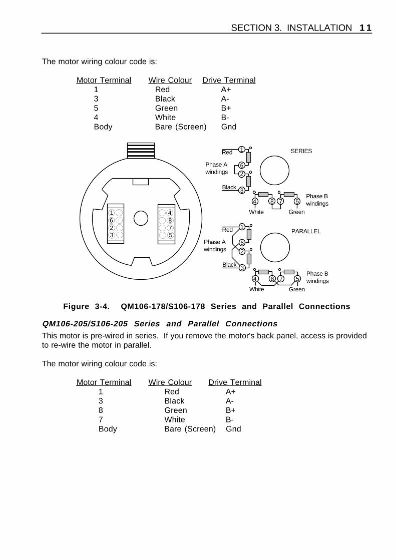
The motor wiring colour code is:
Motor Terminal Wire Colour Drive Terminal 1 Red A+3 Black A-5 Green B+4 White B-Body Bare (Screen) Gnd
Phase Awindings
Phase Bwindings
Red
Black
White Green
784 5
3
26
1
Phase Awindings
Phase Bwindings
Red
Black
White Green
784 5
3
26
1623
1 4875
SERIES
PARALLEL
Figure 3-4. QM106-178/S106-178 Series and Parallel Connections
QM106-205/S106-205 Series and Parallel ConnectionsThis motor is pre-wired in series. If you remove the motor's back panel, access is providedto re-wire the motor in parallel.
The motor wiring colour code is:
Motor Terminal Wire Colour Drive Terminal 1 Red A+3 Black A-8 Green B+7 White B-Body Bare (Screen) Gnd
PDS SERIES DRIVE USER GUIDE1 2
Phase Awindings
Phase Bwindings
Red
Black
White Green
247 8
3
56
1
Phase Awindings
Phase Bwindings
Red
Black
White Green
247 8
3
56
1
2
SERIES
PARALLEL8 4
1 5
63
7
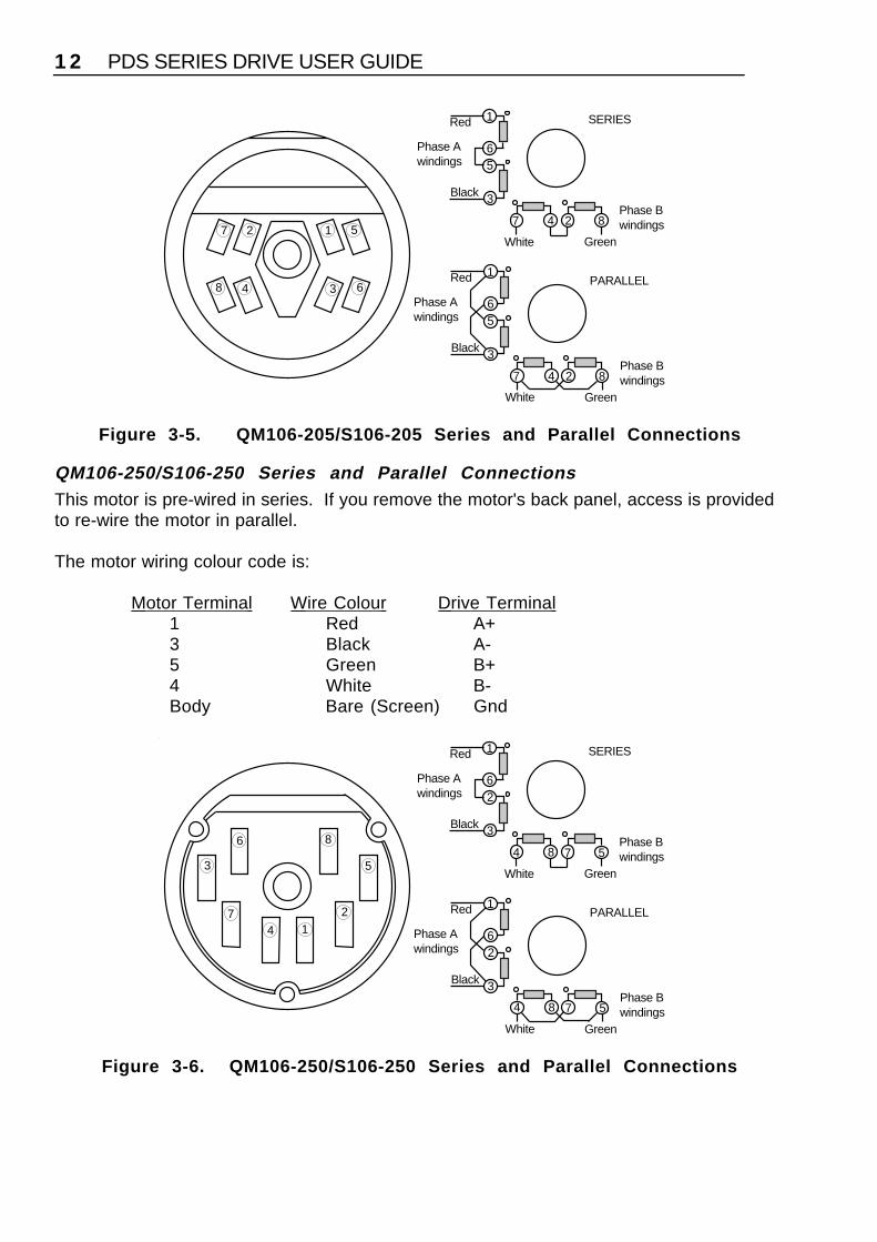
Figure 3-5. QM106-205/S106-205 Series and Parallel Connections
QM106-250/S106-250 Series and Parallel ConnectionsThis motor is pre-wired in series. If you remove the motor's back panel, access is providedto re-wire the motor in parallel.
The motor wiring colour code is:
Motor Terminal Wire Colour Drive Terminal 1 Red A+3 Black A-5 Green B+4 White B-Body Bare (Screen) Gnd
Phase Awindings
Phase Bwindings
Red
Black
White Green
54 78
3
26
1
Phase Awindings
Phase Bwindings
Red
Black
White Green
54 78
3
26
12
SERIES
PARALLEL
8
4 1
5
6
3
7
Figure 3-6. QM106-250/S106-250 Series and Parallel Connections
SECTION 3. INSTALLATION 1 3
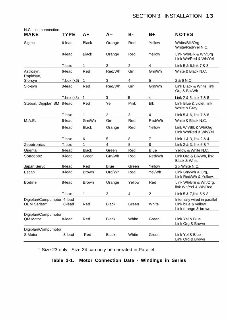
N.C. - no connection.MAKE TYPE A+ A– B- B+ NOTES
Sigma 6-lead Black Orange Red Yellow White/Blk/Org,White/Red/Yel N.C.
8-lead Black Orange Red Yellow Link Wh/Blk & Wh/OrgLink Wh/Red & Wh/Yel
T.box 1 3 2 4 Link 5 & 6,link 7 & 8
Astrosyn, 6-lead Red Red/Wh Grn Grn/Wh White & Black N.C.Rapidsyn,Slo-syn T.box (x6) 1 3 4 5 2 & 6 N.C.
Slo-syn 8-lead Red Red/Wh Grn Grn/Wh Link Black & White, linkOrg & Blk/Wh
T.box (x8) 1 3 5 4 Link 2 & 6, link 7 & 8
Stebon, Digiplan SM 8-lead Red Yel Pink Blk Link Blue & violet, linkWhite & Grey
T.box 1 2 3 4 Link 5 & 6, link 7 & 8
M.A.E. 6-lead Grn/Wh Grn Red Red/Wh White & Black N.C.
8-lead Black Orange Red Yellow Link Wh/Blk & Wh/Org, Link Wh/Red & Wh/Yel
T.box 6 5 8 7 Link 1 & 3, link 2 & 4
Zebotronics T.box 1 4 5 8 Link 2 & 3, link 6 & 7
Oriental 6-lead Black Green Red Blue Yellow & White N.C.
Sonceboz 8-lead Green Grn/Wh Red Red/Wh Link Org & Blk/Wh, linkBlack & White
Japan Servo 6-lead Red Blue Green Yellow 2 x White N.C.
Escap 8-lead Brown Org/Wh Red Yel/Wh Link Brn/Wh & Org,Link Red/Wh & Yellow.
Bodine 8-lead Brown Orange Yellow Red Link Wh/Brn & Wh/Org,link Wh/Yel & Wh/Red.
T.box 1 3 4 2 Link 5 & 7,link 6 & 8
Digiplan/Compumotor 4-lead - - - - Internally wired in parallelOEM Series† 8-lead Red Black Green White Link blue & yellow
Link orange & brown
Digiplan/CompumotorQM Motor 8-lead Red Black White Green Link Yel & Blue
Link Org & Brown
Digiplan/CompumotorS Motor 8-lead Red Black White Green Link Yel & Blue
Link Org & Brown
† Size 23 only. Size 34 can only be operated in Parallel.
Table 3-1. Motor Connection Data - Windings in Series
PDS SERIES DRIVE USER GUIDE1 4
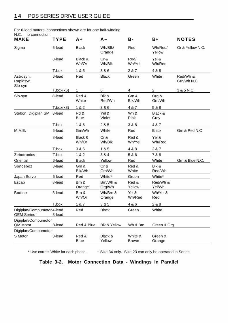
For 6-lead motors, connections shown are for one half-winding.N.C. - no connection.MAKE TYPE A+ A– B- B+ NOTES
Sigma 6-lead Black Wh/Blk/ Red Wh/Red/ Or & Yellow N.C.Orange Yellow
8-lead Black & Or & Red/ Yel &Wh/Or Wh/Blk Wh/Yel Wh/Red
T.box 1 & 5 3 & 6 2 & 7 4 & 8
Astrosyn, 6-lead Red Black Green White Red/Wh &Rapidsyn, Grn/Wh N.C.Slo-syn
T.box(x6) 1 6 4 2 3 & 5 N.C.
Slo-syn 8-lead Red & Blk & Grn & Org &White Red/Wh Blk/Wh Grn/Wh
T.box(x8) 1 & 2 3 & 6 4 & 7 5 & 8
Stebon, Digiplan SM 8-lead Rd & Yel & Wh & Black &Blue Violet Pink Grey
T.box 1 & 6 2 & 5 3 & 8 4 & 7
M.A.E. 6-lead Grn/Wh White Red Black Grn & Red N.C
8-lead Black & Or & Red & Yel &Wh/Or Wh/Blk Wh/Yel Wh/Red
T.box 3 & 6 1 & 5 4 & 8 2 & 7
Zebotronics T.box 1 & 2 3 & 4 5 & 6 7 & 8
Oriental 6-lead Black Yellow Red White Grn & Blue N.C.
Sonceboz 8-lead Grn & Or & Red & Blk &Blk/Wh Grn/Wh White Red/Wh
Japan Servo 6-lead Red White* Green White*
Escap 8-lead Brn & Brn/Wh & Red & Red/Wh &Orange Org/Wh Yellow Yel/Wh
Bodine 8-lead Brn & Wh/Brn & Yel & Wh/Yel &Wh/Or Orange Wh/Red Red
T.box 1 & 7 3 & 5 4 & 6 2 & 8
Digiplan/Compumotor 4-lead Red Black Green WhiteOEM Series† 8-lead
Digiplan/CompumotorQM Motor 8-lead Red & Blue Blk & Yellow Wh & Brn Green & Org.
Digiplan/CompumotorS Motor 8-lead Red & Black & White & Green &
Blue Yellow Brown Orange
* Use correct White for each phase. † Size 34 only. Size 23 can only be operated in Series.
Table 3-2. Motor Connection Data - Windings in Parallel

SECTION 3. INSTALLATION 1 5
Drive Current Setting
SWITCHSETTINGS
PDS13-2PEAK
CURRENT
PDS15-2PEAK
CURRENT6 7 8
ON ON ON 3.0A 5.0AOFF ON ON 2.7A 4.6AON OFF ON 2.4A 4.3AOFF OFF ON 2.1A 3.9AON ON OFF 1.8A 3.6AOFF ON OFF 1.5A 3.2AON OFF OFF 1.2A 2.9AOFF OFF OFF 0.9A 2.5A
Table 3-3. Peak Current Settings
Compumotor S and QM Motor Drive SettingsWhen using Compumotor ‘S’ and ‘QM’ motors you will need to set the PDS drive currentsettings as shown in Table3-4.
The ‘S’ motor and ‘QM’ motor are electrically identical e.g. an S57-51 is the same as QM57-51. In the following table, under motor type, a suffix ‘S’ refers to series connected and ‘P’refers to parallel connected.
Motor Type PDS13-2 PDS15-2 PeakMotor
Rotor Inertia
S W 6 S W 7 S W 8 S W 6 S W 7 S W 8 CurrentRating(Amps)
Kg-cm2
(oz-in2)
S/QM-57-51S ON OFF OFF * * * 1.2 0.088 (0.48)S/QM-57-51P ON OFF ON OFF OFF OFF 2.3S/QM-57-83S OFF ON OFF * * * 1.5 0.234 (1.28)S/QM-57-83P ON ON ON OFF ON OFF 3.1S/QM-57-102S ON ON OFF * * * 1.7 0.32 (1.75)S/QM-57-102P ON ON ON ON ON OFF 3.5S/QM-83-62S OFF OFF ON * * * 2.2 0.64 (3.50)S/QM-83-62P ON ON ON OFF ON ON 4.4S/QM-83-93S ON ON ON ON OFF OFF 2.9 1.23 (6.70)S/QM-83-93P X X X ON ON ON 5.6S/QM-83-135S ON ON ON ON ON OFF 3.5 1.87 (10.24)S/QM-83-135P X X X ON ON ON 6.9
Table 3-4. PDS Current Drive Settings for Compumotor ‘S’ and ‘QM’ Motors
PDS SERIES DRIVE USER GUIDE1 6
Motor Type PDS13-2 PDS15-2 PeakMotor
Rotor Inertia
S W 6 S W 7 S W 8 S W 6 S W 7 S W 8 CurrentRating(Amps)
Kg-cm2
(oz-in2)
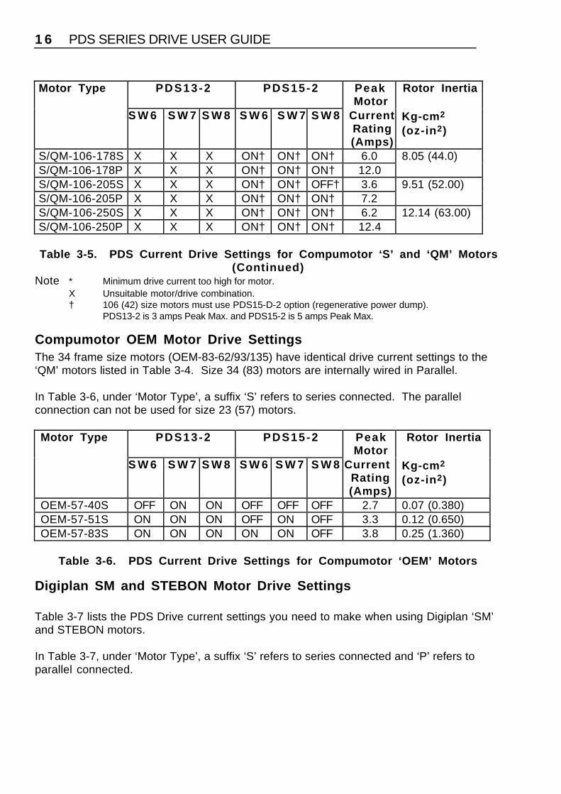
S/QM-106-178S X X X ON† ON† ON† 6.0 8.05 (44.0)S/QM-106-178P X X X ON† ON† ON† 12.0S/QM-106-205S X X X ON† ON† OFF† 3.6 9.51 (52.00)S/QM-106-205P X X X ON† ON† ON† 7.2S/QM-106-250S X X X ON† ON† ON† 6.2 12.14 (63.00)S/QM-106-250P X X X ON† ON† ON† 12.4
Table 3-5. PDS Current Drive Settings for Compumotor ‘S’ and ‘QM’ Motors(Continued)
Note * Minimum drive current too high for motor.X Unsuitable motor/drive combination.† 106 (42) size motors must use PDS15-D-2 option (regenerative power dump).
PDS13-2 is 3 amps Peak Max. and PDS15-2 is 5 amps Peak Max.
Compumotor OEM Motor Drive SettingsThe 34 frame size motors (OEM-83-62/93/135) have identical drive current settings to the‘QM’ motors listed in Table 3-4. Size 34 (83) motors are internally wired in Parallel.
In Table 3-6, under ‘Motor Type’, a suffix ‘S’ refers to series connected. The parallelconnection can not be used for size 23 (57) motors.
Motor Type PDS13-2 PDS15-2 PeakMotor
Rotor Inertia
S W 6 S W 7 S W 8 S W 6 S W 7 S W 8 CurrentRating(Amps)
Kg-cm2
(oz-in2)
OEM-57-40S OFF ON ON OFF OFF OFF 2.7 0.07 (0.380)OEM-57-51S ON ON ON OFF ON OFF 3.3 0.12 (0.650)OEM-57-83S ON ON ON ON ON OFF 3.8 0.25 (1.360)
Table 3-6. PDS Current Drive Settings for Compumotor ‘OEM’ Motors
Digiplan SM and STEBON Motor Drive Settings
Table 3-7 lists the PDS Drive current settings you need to make when using Digiplan ‘SM’and STEBON motors.
In Table 3-7, under ‘Motor Type’, a suffix ‘S’ refers to series connected and ‘P’ refers toparallel connected.

SECTION 3. INSTALLATION 1 7
Motor Type PDS13-2 PDS15-2 PeakMotor
Rotor Inertia
S W 6 S W 7 S W 8 S W 6 S W 7 S W 8 CurrentRating(Amps)
Kg-cm2
(oz-in2)
SM-57-51S OFF OFF OFF * * * 1.1 0.11 (0.60)SM-57-51P OFF OFF ON * * * 2.1SM-57-83S OFF OFF ON * * * 2.3 0.23 (1.26)SM-57-83P ON ON ON OFF ON ON 4.7SM-57-102S OFF OFF ON * * * 2.3 0.30 (1.64)SM-57-102P ON ON ON OFF ON ON 4.6SM-83-62S ON ON ON OFF ON OFF 3.2 0.60 (3.30)SM-83-62P X X X ON ON ON 6.4SM-83-93S ON ON ON OFF OFF ON 4.0 1.25 (6.83)SM-83-93P X X X ON ON ON 7.9SM-83-135S ON ON ON ON ON OFF 3.8 2.00 (10.93)SM-83-135P X X X ON ON ON 7.6SM-106-140S X X X OFF† ON† ON† 5.0 3.65 (19.96)SM-106-140P X X X ON† ON† ON† 9.9
Table 3-7. PDS Current Drive Settings for Digiplan ‘SM’ and STEBONMotors
Note * Minimum drive current too high for motor.X Unsuitable motor/drive combination.† 106 (42) size motors must use PDS15-D-2 option (regenerative power dump).
PDS13-2 is 3 amps Peak Max. and PDS15-2 is 5 amps Peak Max.
Signal Connections
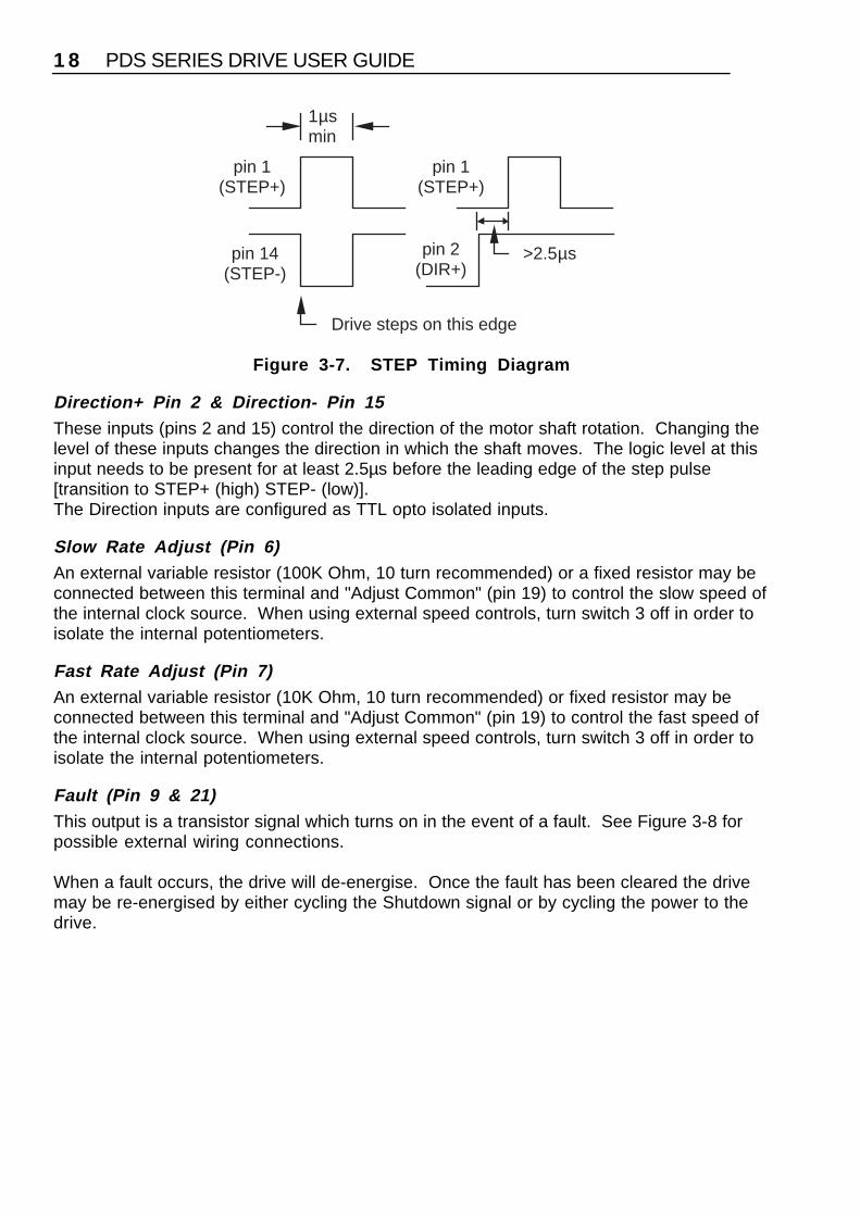
Step + Pin 1 & Step- Pin 14A pulse on these inputs causes the motor to advance on the leading edge of the pulse (seeFigure 3-7). The pulse should be at least 1µs long. Consult your indexer user guide forinstructions on how to change the output pulse width.The Step inputs are configured as TTL opto isolated inputs.
PDS SERIES DRIVE USER GUIDE1 8
pin 1(STEP+)
pin 14(STEP-)
1µsmin
Drive steps on this edge
pin 1(STEP+)
pin 2(DIR+)
>2.5µs
Figure 3-7. STEP Timing Diagram
Direction+ Pin 2 & Direction- Pin 15These inputs (pins 2 and 15) control the direction of the motor shaft rotation. Changing thelevel of these inputs changes the direction in which the shaft moves. The logic level at thisinput needs to be present for at least 2.5µs before the leading edge of the step pulse[transition to STEP+ (high) STEP- (low)].The Direction inputs are configured as TTL opto isolated inputs.
Slow Rate Adjust (Pin 6)An external variable resistor (100K Ohm, 10 turn recommended) or a fixed resistor may beconnected between this terminal and "Adjust Common" (pin 19) to control the slow speed ofthe internal clock source. When using external speed controls, turn switch 3 off in order toisolate the internal potentiometers.
Fast Rate Adjust (Pin 7)An external variable resistor (10K Ohm, 10 turn recommended) or fixed resistor may beconnected between this terminal and "Adjust Common" (pin 19) to control the fast speed ofthe internal clock source. When using external speed controls, turn switch 3 off in order toisolate the internal potentiometers.
Fault (Pin 9 & 21)This output is a transistor signal which turns on in the event of a fault. See Figure 3-8 forpossible external wiring connections.
When a fault occurs, the drive will de-energise. Once the fault has been cleared the drivemay be re-energised by either cycling the Shutdown signal or by cycling the power to thedrive.

SECTION 3. INSTALLATION 1 9
FAULT+921
FAULT-
1K2
+12V
0V
FAULT+921 FAULT-
4K7
+24V max
0V
OR
RemoteIndicator
Figure 3-8. Fault Output Examples
Slow Run (Pin 12)Connect this input to GND directly to run the internal clock source at the slow rate.
Fast Run (Pin 13)Connect this input to GND directly to run the internal clock source at the fast rate.
Shutdown+ Pin 16 & Shutdown- Pin 17These differential inputs (pins 16 and 17) are used to energise and de-energise (shutdown)the motor. When the shutdown+ input is taken high and shutdown- is low, the drive is shutdown and, if it is safe to do so, the motor shaft may be rotated slowly by hand.
NOTE: Back-driving the motor at excessive speed may damage the drive.
Cycling the shutdown input resets a fault condition, provided the cause of the fault has beenremoved.
Adjust Common (Pin 19)Common return connection for external speed controls (nominal +12V).
Internal Clock Out (Pin 20)This open collector output (NPN transistor) goes low every time the drive sees a step pulsefrom the internal clock source. It must be pulled up using an external resistor. Pulse widthis 1µs, consequently this clock is not compatible with the Aux Clock In on pin 23, since thepulse width is too narrow to pass through the input filter. It cannot therefore be connected tothe Aux Clock In on another drive in order to slave two drives from one oscillator. Shouldyou wish to do this, you will need to feed the Internal Clock Out via a differential driver intothe Step+/Step- inputs on the second drive.
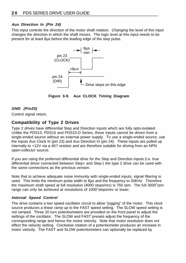
Aux Clock In (Pin 23)A low going pulse on this input causes the motor to advance on the leading edge of thepulse (see Figure 3-9). The pulse should be at least 8µs long. Consult your indexer userguide for instructions on how to change the output pulse width.
PDS SERIES DRIVE USER GUIDE2 0
Aux Direction In (Pin 24)This input controls the direction of the motor shaft rotation. Changing the level of this inputchanges the direction in which the shaft moves. The logic level at this input needs to bepresent for at least 8µs before the leading edge of the step pulse.
pin 23(CLOCK)
8µsmin
Drive steps on this edge
pin 24(DIR)
>8µs
Figure 3-9. Aux CLOCK Timing Diagram
GND (Pin25)Control signal return.
Compatibility of Type 2 DrivesType 2 drives have differential Step and Direction inputs which are fully opto-isolated.Unlike the PDS13, PDS15 and PDS15-D Series, these inputs cannot be driven from asingle-ended source without an external power supply. To use a single-ended source, usethe inputs Aux Clock In (pin 23) and Aux Direction In (pin 24). These inputs are pulled upinternally to +12V via a 4K7 resistor and are therefore suitable for driving from an NPNopen-collector source.
If you are using the preferred differential drive for the Step and Direction inputs (i.e. truedifferential driver connected between Step+ and Step-) the type 2 drive can be used withthe same connections as the previous version.
Note that to achieve adequate noise immunity with single-ended inputs, signal filtering isused. This limits the minimum pulse width to 8µs and the frequency to 50KHz. Thereforethe maximum shaft speed at full resolution (4000 steps/rev) is 750 rpm. The full 3000 rpmrange can only be achieved at resolutions of 1000 steps/rev or lower.
Internal Speed ControlThe drive contains a two speed oscillator circuit to allow “jogging” of the motor. This clocksource produces a linear ramp up to the FAST speed setting. The SLOW speed setting isnot ramped. Three 20 turn potentiometers are provided on the front panel to adjust thesettings of the oscillator. The SLOW and FAST presets adjust the frequency of thecorresponding range and hence the motor velocity. Note that motor resolution does noteffect the velocity setting. Clockwise rotation of a potentiometer produces an increase inmotor velocity. The FAST and SLOW potentiometers can optionally be replaced by

SECTION 3. INSTALLATION 2 1
externally wired, remote potentiometers - see Figure 3-10. These external controls can beused to give a machine operator remote control of the motor.
Clockwise rotation of the ACCEL potentiometer increases the rate of motor ramp up to amaximum possible figure of 500 rps2. The ACCEL potentiometer can not be replaced by anexternal variable resistor.
Optional Advance Rate Pot and Switch ConnectionsFigure 3-10 shows typical external connections required when using the internal clocksource. External variable resistance values of 100K for Slow and 10K for Fast arerecommended.When using external speed controls, turn switch 3 off in order to isolate the internalpotentiometers.
OptionalFast Adj.10KΩ
Slow Run
Aux Clk In
Shutdown +
560Ω
OptionalSlow Adj.100KΩ
114
1325Aux Dir In
Fast Run
DIR
Note: Screened cable should be used (maximum length 2 metres)Figure 3-10. Signal Connections
PDS SERIES DRIVE USER GUIDE2 2
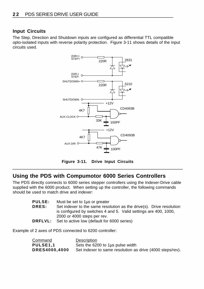
Input CircuitsThe Step, Direction and Shutdown inputs are configured as differential TTL compatibleopto-isolated inputs with reverse polarity protection. Figure 3-11 shows details of the inputcircuits used.
220R 5210SHUTDOWN+
SHUTDOWN-
220R 2631(DIR+)STEP+
(DIR-)STEP-
4K7
33K100PF
+12V
AUX CLOCK
CD4093B
4K7
47K 100PF
+12V
AUX DIR
CD4093B
Figure 3-11. Drive Input Circuits
Using the PDS with Compumotor 6000 Series ControllersThe PDS directly connects to 6000 series stepper controllers using the Indexer-Drive cablesupplied with the 6000 product. When setting up the controller, the following commandsshould be used to match drive and indexer:
PULSE: Must be set to 1µs or greaterDRES: Set indexer to the same resolution as the drive(s). Drive resolution
is configured by switches 4 and 5. Valid settings are 400, 1000, 2000 or 4000 steps per rev.
DRFLVL: Set to active low (default for 6000 series)
Example of 2 axes of PDS connected to 6200 controller:
Command Description PULSE1,1 Sets the 6200 to 1µs pulse widthDRES4000,4000 Set indexer to same resolution as drive (4000 steps/rev).

SECTION 3. INSTALLATION 2 3
DRFLVL0 Fault signals are active lowINFEN1 Enable input functions
Note that if a drive fault occurs and is cleared, a 6000 controller can automatically reset thedrive latch by toggling the shutdown input signal as follows:
Command Description DRIVE00 Shutdown both axes (motors de-energised)DRIVE11 Enable both drives and clear fault latches.
Mechanical/ EnvironmentalThe drive and its switch mode power supply are contained in a single case measuring250mm (9.84 inches) High, by 50mm (1.97 inches) Wide, by 190mm (7.5 inches) Deep.Note: The depth does not take connector dimensions into account. These need anadditional 60mm.
You should install the drive system in an enclosure to protect it against atmosphericcontaminants such as oil, moisture, dirt etc. This also prevents operator access and assiststhe EMC performance by limiting emissions and adding to the rf immunity.
Ideally, you should install the system in a cabinet. In the USA, the National ElectricalManufacturers Association (NEMA) has established standards that define the degree ofprotection that electrical enclosures provide. The enclosure should conform to NEMA Type12 standards if the intended environment is industrial and contains airborne contaminants.Proper layout of components is required to ensure sufficient cooling of equipment within theenclosure.
Environmental
Digiplan recommends you operate and store your PDS Drive system under the followingconditions:
• Operating Temperature: 0° to 40°C (32° to 104°F)• Relative Humidity: 0% to 95% (non-condensing)• Storage Temperature: -40° to 85°C (-40° to 185°F)
The recommended orientation of the drive enclosure is back panel, vertical mounting.
In exceptional circumstances, such as running the motor continuously at maximum current,forced-air cooling may be needed to maintain the local ambient temperature withinspecification.
The mains input to the drive should be Installation Category II maximum.
The PDS series of drives can be used in a Pollution Degree 2 environment i.e., one inwhich only non-conductive pollution occurs.

PDS SERIES DRIVE USER GUIDE2 4
Installation ConsiderationsThe drive is designed to be installed vertically as shown in Figure 3-12. Air vents on the topand bottom panels allow convection cooling.At least 50mm minimum clearance around the air vents is recommended for unobstructedventilation and reliable operation.
9.3 (0.37)
25.0 (0.98)
250.0(9.84)
222.0(8.74)
237.25(9.34)
7.5(0.30) 35.0
(1.38)
50.0(1.96)
7.75 (0.30)
4.5 (0.18) Dia
8.6 (0.34)Dia
4.3 (0.17)
Betweencentres
Mounting holedetails
Note1. All dimensions are given in millimetres and (inches). 2. Overall depth is 190mm (7.5 inches) excluding connectors.3. Overall width including screw heads 54.0 (2.13 inches)4. Recommended fixing screw size M4 or #8
Slots4.5 (0.18)
wide
Figure 3-12 Drive Mounting Hole Locations
SECTION 3. INSTALLATION 2 5
EMC InstallationIt should be stressed that although these recommendations are based on the expertiseacquired during the development of fully compliant products, and on tests carried out oneach of the product types, it is impossible for Digiplan to guarantee the compliance of anyparticular installation. This will be strongly influenced by the physical and electrical detailsof the installation and the performance of other system components. Nevertheless it isimportant to follow all the installation instructions if an adequate level of compliance is to berealisable.
External enclosuresThe measures described in these recommendations are primarily for the purpose ofcontrolling mains conducted emissions. To control radiated emissions, all PDS drives andrack systems must be installed in a steel equipment cabinet which will give adequatescreening against radiated emissions. This external enclosure is also required for safetyreasons. With the exception of drive front panels in rack-based units, there must be no useraccess while the equipment is operating. This is usually achieved by fitting an isolatorswitch to the door assembly. Drives and filters must be mounted to a conductive panel. Ifthis has a paint finish, it will be necsssary to remove the paint in certain areas whererequired.
To achieve adequate screening of radiated emissions, all panels of the enclosure must bebonded to a central earth point. The enclosure may also contain other equipment such asmotion controllers, and the EMC requirements of these must be considered duringinstallation. Always ensure that drives and rack systems are mounted in such a way thatthere is adequate ventilation.
Before mounting the drive, remove the paint from the rear face of the lower mounting lug asshown in Figure 3-13 (if not already removed), and if necessary from the correspondingarea on the rear panel of the enclosure. This is to guarantee a good high-frequencyconnection between the drive case and the cabinet. Use petroleum jelly on the exposedmetal to minimise the risk of future corrosion.
AC Supply FilteringThese recommendations are based on the use of proprietary mains filter units which arereadily available. However, the full EMC test includes a simulated lightning strike which willdamage the filter unless adequate surge suppression devices are fitted. These are notnormally incorporated into commercial filters since the lightning strike test can bedestructive. This test is normally carried out on the overall system and not on individualcomponents, therefore the surge protection should be provided at the system boundary.
Try to arrange the layout of drive and filter so that the AC input cable is kept away from thefilter output leads. It is preferable for the current path to be as linear as possible withoutdoubling back on itself - this can negate the effect of the filter. Mount the filter within 50mmof the drive, and run the input cable and any earth cables close to the panel.

PDS SERIES DRIVE USER GUIDE2 6
PDS drives incorporate a switch-mode power supply operating directly from the AC input.The substantial filtering effect of a mains isolation transformer is therefore not available, andadditional external filtering is required. The solution offered uses a single filter in order tocontrol both differential and common-mode emissions. The manufacturer’s part number fora suitable filter is:
CORCOM 6EQ1
Mount the filter within 50mm of the drive as shown in Figure 3-13. Again ensure that thereis no paint on the rear panel behind the filter mounting lugs - it is vital that there is goodlarge-area contact between the filter and the panel.
Mains CableConnect the incoming AC supply cable to the push-on terminals on the ‘LINE’ end of thefilter, with the earth lead connected to a local earth stud or bus bar. Connect the earthterminal on the case of the filter to the earth stud. Route the supply cable so that it runsclose to the rear panel within the cabinet.
3-core 1mm2 screened cable (with a braided screen) must be used between the output ofthe filter and the input to the drive with a voltage rating of at least 1350V AC. Connect theearth wire to the earth stud, and arrange all the earth leads so thay they run close to thepanel. Expose a short length of the screen and anchor the cable close to the filter with a P-clip. Remove any paint from the panel behind the P-clip. Fit a ferrite absorber over thecable and wire up the power connector - no connection is made to the screen at the driveend. Locate the absorber as close as possible to the connector using heat-shrink sleeving.

SECTION 3. INSTALLATION 2 7
AC InputCable
FilterCORCOM6EQ1
LINE
P-clips securedto back panel Motor
cable
Removepaint frombehind thisarea
I/O Cable
Ferriteabsorber
Braided-screencables
No morethan 50mm
LOAD
Figure 3-13. EMC Installation
Motor cablesAll motor connections must be made using a high quality braided-screen cable. Cablesusing a metallised plastic bandage for an earth screen are unsuitable and in fact providevery little screening. There is a problem in terminating to the screen in a mechanicallystable manner and the screen itself is comparatively fragile - bending it round a tightradius can seriously affect the screening performance.
There must be no break in the 360° high optical coverage that the screen provides aroundthe cable conductors. If a connector must be used it should retain the 360° coverage,possibly by the use of an additional metallic casing where it passes through the bulkhead ofthe enclosure. The cable screen must not be bonded to the cabinet at the point of entry. Itsfunction is to return high-frequency chopping current back to the drive. This may requiremounting the connector on a sub-panel insulated from the main cabinet, or using aconnector having an internal screen which is insulated from the connector housing.

PDS SERIES DRIVE USER GUIDE2 8
Within the cabinet itself, all the motor cables should lie in the same trunking as far aspossible. They must be kept separate from any low-level control signal cables. Thisapplies particularly where the control cables are unscreened and run close to the drive orrack system.
Stepper motorsIt is preferable to use motors with screw terminations whenever possible. If flying-leadmotors are used, it is important that the unscreened leads are converted into a braided-screen cable within 100mm of the motor body. A separate terminal box may be used forthis purpose but the braided cable screen must be properly strapped to the motor body.Motors fitted with terminal boxes also allow local selection of series or parallel connection,reducing the cost of the cable running back to the drive.
Motor connections
Use 5-core 1mm2 screened cable for the motor connections, for example Lapp 34805. Atthe drive end, fit a ferrite absorber over the cable before wiring to the motor connector. Noconnection is made to the cable screen at this end. Locate the absorber as close aspossible to the connector using heat-shrink sleeving.
Run the motor cable back to the rear panel and down between the drive and the filters.Expose a short length of braiding and anchor to the rear panel with a P-clip. Note that themotor cable should preferably be kept at least 300mm away from I/O cables carrying controlsignals.
Termination at the motor must be made using a 360° bond to the motor body, and this maybe achieved by using a suitable clamp. Many stepper motors are designed toaccommodate an appropriate conductive terminal gland which can be used for thispurpose.
Control signal wiringHigh-quality braided screen cable should be used for control connections. In the case ofthe PDS drive which has differential step-direction inputs, it is preferable to use cable withtwisted pairs to minimise magnetic coupling. No connection is made to the cable screen atthe D-connector on the drive. Fit a ferrite absorber close to the D-connector and run thecable back to the rear panel as shown in Figure 3-13. Expose a short length of the braidedscreen and anchor to the rear panel with a P-clip.
Ferrite absorber specificationsThe absorbers described in these installation instructions are made from a low-grade ferritematerial which has high losses at radio frequencies. They therefore act like a highimpedance in this waveband.

SECTION 3. INSTALLATION 2 9
The recommended components are produced by Parker Chomerics and are suitable foruse with cable having an outside diameter up to 10mm. The specification is as follows:
Chomerics part number H8FE-1115-NCOutside diameter 17.5mmInside diameter 10.7mmLength 28.5mmImpedance at 25MHz 80Impedance at 100MHz 120Curie temperature 130°C (the device should not be operated near this
temperature)
Handling and installing the ferrite absorbersTake care when handling the absorbers - they can shatter if dropped on a hard surface.For this reason the suggested method of installation is to use a short length of 19mmdiameter heat-shrink sleeving. This gives a degree of physical protection while the cable isbeing installed. The sleeving should have a shrink ratio of at least 2.5:1. Cable ties may beused as an alternative, however they give no physical protection to the absorber.

PDS SERIES DRIVE USER GUIDE3 0
SECTION 4. SETTING UP 3 1
Section 4. Setting Up
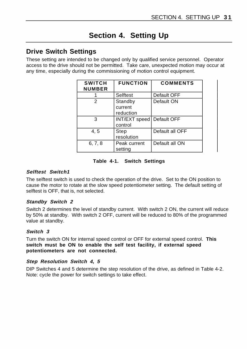
Drive Switch SettingsThese setting are intended to be changed only by qualified service personnel. Operatoraccess to the drive should not be permitted. Take care, unexpected motion may occur atany time, especially during the commissioning of motion control equipment.
SWITCHNUMBER
FUNCTION COMMENTS
1 Selftest Default OFF2 Standby
currentreduction
Default ON
3 INT/EXT speedcontrol
Default OFF
4, 5 Stepresolution
Default all OFF
6, 7, 8 Peak currentsetting
Default all ON
Table 4-1. Switch Settings
Selftest Switch1The selftest switch is used to check the operation of the drive. Set to the ON position tocause the motor to rotate at the slow speed potentiometer setting. The default setting ofselftest is OFF, that is, not selected.
Standby Switch 2Switch 2 determines the level of standby current. With switch 2 ON, the current will reduceby 50% at standby. With switch 2 OFF, current will be reduced to 80% of the programmedvalue at standby.
Switch 3Turn the switch ON for internal speed control or OFF for external speed control. Thisswitch must be ON to enable the self test facility, if external speedpotentiometers are not connected.
Step Resolution Switch 4, 5DIP Switches 4 and 5 determine the step resolution of the drive, as defined in Table 4-2.Note: cycle the power for switch settings to take effect.
3 2 PDS SERIES DRIVE USER GUIDE
SWITCHSETTINGS
RESOLUTIONIN STEPS/REV
4 5ON ON 400ON OFF 1000OFF ON 2000OFF OFF 4000
Table 4-2. Step Resolution Settings
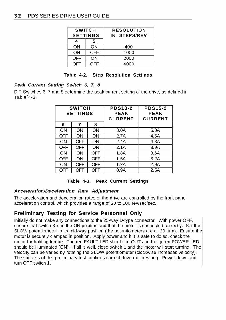
Peak Current Setting Switch 6, 7, 8DIP Switches 6, 7 and 8 determine the peak current setting of the drive, as defined inTable 4-3.
SWITCHSETTINGS
PDS13-2PEAK
CURRENT
PDS15-2PEAK
CURRENT6 7 8
ON ON ON 3.0A 5.0AOFF ON ON 2.7A 4.6AON OFF ON 2.4A 4.3AOFF OFF ON 2.1A 3.9AON ON OFF 1.8A 3.6AOFF ON OFF 1.5A 3.2AON OFF OFF 1.2A 2.9AOFF OFF OFF 0.9A 2.5A
Table 4-3. Peak Current Settings
Acceleration/Deceleration Rate AdjustmentThe acceleration and deceleration rates of the drive are controlled by the front panelacceleration control, which provides a range of 20 to 500 rev/sec/sec.
Preliminary Testing for Service Personnel OnlyInitially do not make any connections to the 25-way D-type connector. With power OFF,ensure that switch 3 is in the ON position and that the motor is connected correctly. Set theSLOW potentiometer to its mid-way position (the potentiometers are all 20 turn). Ensure themotor is securely clamped in position. Apply power and if it is safe to do so, check themotor for holding torque. The red FAULT LED should be OUT and the green POWER LEDshould be illuminated (ON). If all is well, close switch 1 and the motor will start turning. Thevelocity can be varied by rotating the SLOW potentiometer (clockwise increases velocity).The success of this preliminary test confirms correct drive-motor wiring. Power down andturn OFF switch 1.

SECTION 4. SETTING UP 3 3
If you wish, you can now plug in your Compumotor Indexer cable and test the drive usingthe indexer. Alternatively, by making the wiring connections shown in Figure 3-10 you canoperate the drive via the internal clock source.
Digiplan
PowerFaultFastSlowAccel
Self TestStandbyInt clk adjResolution
Motor Current
1 Step+2 Dirn+3 -4 -5 -6 Slow Adj7 Fast Adj8 -9 Fault+10 -11 -12 Slow13 Fast14 Step-15 Dirn-16 Shut+17 Shut-18 -19 Adj Com20 Int clk out21 -22 -23 -Aux Clk24 -Aux Dir25 GND
A+A-GndB+B-
PDSSERIES Parker
ON OFF
SWITCHSETTINGS
110-240V50-60 Hz
Max. power 300VA
Figure 4-1. Front Panel Layout

3 4 PDS SERIES DRIVE USER GUIDE

SECTION 5. MAINTENANCE & TROUBLESHOOTING 3 5
Section 5. Maintenance & Troubleshooting
MaintenanceYour attention is drawn to the safety warning given at the beginning of this User Guide.During troubleshooting be aware that unexpected motion may occur at any time.
Routine maintenance is not necessary, but occasional checking of the following points isrecommended.
Motor MaintenancePeriodically check the motor to ensure that no bolts or couplings have become loose duringoperation, and check the motor cable or leads periodically for signs of wear. Do not makevery tight bends or pull on the cable during normal operation. Check all cable connectors.
Drive MaintenanceCheck that the drive is clear of loose material and has a free flow of air through theventilation slots. Enclosures must be connected to earth ground to provide a low-impedance path for ground-fault or noise-induced currents. Check the security of theground connections.
Troubleshooting
Fault LEDThe red LED indicates one of the following fault conditions:
1. Motor wiring short-circuit either across phases or between phases.2. Motor wiring short-circuit phase to GND (earth).3. Motor supply overvoltage or undervoltage.4. Internal supply failure.5. Drive internal overtemperature.
The fault LED will also light up if the motor is decelerating a high inertia load too quickly.The drive will shut down under this condition. If this occurs, you can either reduce thedeceleration rate/load inertia, or use a PDS15-D-2 (power dump option). SeeINSTALLATION section for more information on the regenerative power dump option.
Note that the fault LED comes on momentarily when power is removed from the drive. Thisis caused by the supply rails dropping below a safe operating level, and is an indicationthat the fault circuitry is functioning correctly. You should always ensure that the fault LEDis extinguished before re-applying the power.
Motor Fails to MoveIf it is safe to do so, test the motor to see if it has holding torque. If there is no holdingtorque, here are some probable causes:

3 6 PDS SERIES DRIVE USER GUIDE
• There is no power.
• Current DIP switch selection is not set properly.
• There are bad connections or bad cables in the motor circuit. Disconnect the powerto the drive and remove the motor connector. Using a meter, check the continuity in themotor circuit between pins A+ and A- of the motor connector. Repeat for pins B+ and B-.
• Check the resistance of the motor and cables to make sure that shorts do not existbetween phases or to earth GND. The resistance across each motor phase should beconsistent and there should be no connection between motor phases and between eachphase and earth ground.
• Check the motor cables for signs of damage.
• The shutdown input may be active.
• If the power LED is out and the motor will not energise, the drive must be returned forrepair.
If the unit has holding torque and the motor shaft still fails to move, here are some possiblecauses:
• The load is jammed. You should hear the drive attempting to move the motor.Remove power from the driver and verify that you can move the load manually away fromthe point of the jam.
• Clock pulses are not reaching the drive, or the signal levels are inadequate. Ifpossible, check the signal levels with an oscilloscope. Try running the motor using the self-test switch.
Motor StallsA motor stall during acceleration may be caused by one or more of the following factors:
• The torque requirements may be excessive.
• The acceleration ramp may be too steep - lower acceleration may be required.Check the torque/speed curves in the published data and make sure you are trying to runthe motor within the system capabilities.
• The load inertia and rotor inertia may be grossly mismatched.
If the motor stalls during the constant velocity portion of a move, the shaft and/or couplermay be damaged or binding due to improper coupling or excessive motor load.

SECTION 5. MAINTENANCE & TROUBLESHOOTING 3 7
A stall may occur if the switch setting for the motor current selection is incorrect. The motormay not be receiving enough current to drive the load.
Motor is Jerky or WeakCheck that there are no mechanical problems at the load causing variable loadingconditions. Disconnect the motor from the load and run it without a load connected. Checkthe switch current settings.
Motor OverheatsIf the motor exceeds its maximum motor case temperature rating, failure will eventuallyresult. Check your switch settings to ensure that the current setting is correct for the motoryou are using.
Motor Runs the Wrong WayTurn off the power and interchange the connections between A+ and A- on the motorconnector.
Internal Clock Source Will Not RunIf no external speed controls are used, check that switch 3 is ON so that the internalpotentiometers are functional.
Self Test Fails to Run MotorSee above.
Returning the SystemContact the Parker Automation Technology Centre or the machinery manufacturer whosupplied the product. Equipment for repair should NOT be returned directly to Digiplanwithout prior authorisation. Repairs will be carried out by Digiplan but will be processed viayour supplier.
Digiplan may at their discretion authorise direct shipment to and from Poole or RohnertPark, but only by prior arrangement with your supplier. Existing UK and USA customerswho purchase equipment directly from Digiplan should contact Poole or Rohnert Park forfurther information (contact numbers are at the front of this User Guide).

3 8 PDS SERIES DRIVE USER GUIDE

INDEX 3 9
Index66000 Series Controllers, 22AAcceleration adjustment, 32Acceleration rate, 32Adjust common return, 19Auxiliary clock input, 19Auxiliary clock timing, 20Auxiliary direction input, 20BBipolar rating, 8CCabinet requirements, 7Cable layout precautions, 25Case dimensions, 23Clock internal, 19Clock output, 19Clock source (int.) will not run, 37Clock source control inputs, 19Clock/step options, 1Compatibility of type 2 drives, 20Compumotor 6000 Series, 22Conducted emissions, 25Conductive terminal gland, 28Control signal wiring (EMC), 28Control signals., 5Cooling considerations, 23Current peak setting switch 6, 7 & 8, 32Current settings peak, 32DDimensions of drive, 24Direction input, 18Direction of rotation, 9Drive maintenance, 35Drive setup, 31Dump option, 8Dump option calculations, 8EEarthing requirements, 7EMC Installation, 25EMC installation diagram, 27EMI reduction, 7Environment specification, 5European Standard EN 61010-1, 7
FFast Rate, 18Fault LED, 35Fault output, 18Ferrite absorber, 28Ferrite absorber handling procedures, 29Ferrite absorber specification, 29Filter mounting requirements, 26Filter types for EMC, 26Filtering of AC supply, 25Flame barrier, 7Frame size 42 (106) motors, 10Fuse for dump circuit, 4Fuses internal, 4GGrounding, 7HHolding torque faults, 36Humidity, storage, 23IInstallation requirements, 7Insulation rating of mains wiring, 7Insulation rating of motor, 9Insulation rating of motor cable, 9Interlocks, 7LLong motor leads, 8MMains cable EMC installation, 26Mains input installation category, 23Maintenance, 35Motor cable termination, 28Motor cables (EMC), 27Motor connection fault, 36Motor connections, 9Motor connections (EMC), 28Motor current optimum value, 8Motor earth connection, 9Motor fails to move, 35Motor maintenance, 35Motor specification, 5Motor torque considerations, 8Motor type, 1Mounting clearance, 24Mounting recommendations, 23

CD60M/CD80M STEPPER DRIVE USER GUIDE4 0
Multiple lead motors, 8NNEMA, 23No holding torque faults, 36OOEM Motor drive, 16Overheating, 37PParallel connections, 14PDS series, 1Phase to earth faults, 36Pollution degree, 23Power dump calculation program, 8Product description, 1QQM Motor drive settings, 15QM motors, 10QM106-178 Motor wiring, 11QM106-205 Motor wiring, 11QM106-250 Motor wiring, 12RRadiated emissions, 25Rate adjustment, 18Returning the system, 37Reverse motor direction, 37SS Motor drive settings, 15S motors, 10S106-178 Motor wiring, 11S106-205 Motor wiring, 11S106-250 Motor wiring, 12Safety earth connection to the motor, 10
Selftest selection, 31Selftest switch 1, 31Series connection, 13Shutdown input, 19Single ended performance limitations, 20Slow Rate, 18Specification, 3Speed control external, 21Speed control internal, 21Speed control options, 2Speed control switch 3, 31Speed selection INT or EXT, 31Stalling, 36Standby selection, 31Standby switch 2, 31Stebon motors, 16Step input, 17Step resolution switch 4 & 5, 31Step timing diagram, 17Stepper motor EMC requirements, 28Surge protection, 25Switch settings, 31TTemperature of motor warning, 10Temperature rating of motor cable, 9Temperature, operating, 23Temperature, storage, 23Testing the drive, 32Type 2 series of drives, 1UUnipolar rating, 8

INDEX 4 1

CD60M/CD80M STEPPER DRIVE USER GUIDE4 2