peck feed control - zampini industrial · a peck feed kit controls the sequence by allowing a small...
TRANSCRIPT

www.desouttertools.com
Part no 2050559783Issue no 02Date 04/2013Page 1 / 12
Peck Feed Control
Model Part numberD4 25mm (1") 92282D5 50mm (2”) 92292D6 75mm (3”) 92302
Software and documentation available at:
http://cadfiles.desouttertools.comNo login/password required.
Original instructions.
© CoPyright 2013, DeSoutter hP2 7SJ uKAll rights reserved. Any unauthorized use or copying of the contents or part thereof is prohibited. This applies in particular to trademarks, model denominations, part numbers and drawings. Use only authorized parts. Any damage or malfunction caused by the use of unauthorised parts is not covered by Warranty or Product Liability.

2050559783_02
2 / 12 04/2013
1. PeCK FeeD KitS
type Part No.
D4 25mm (1") 92282
D5 50mm (2”) 92292
D6 75mm (3”) 92302
A peck feed kit controls the sequence by allowing a small depth to be drilled, the tool retracts rapidly, a further depth is drilled, the tool retracts again, etc .. until the final depth is reached and the tool returns to datum.
1st Peck
Return toDatum
Controlledfeed rate(Drilling)
Rapidretract
Depth
2nd Peck
3rd Peck
Final drill
1.1. Circuit diagram
Emergencyretract
A1 Controlblock
Locking unit
Checkunit
DatumSignal
Start
Air in
PECKING MODULE
2050559783_02
3 / 1204/2013
2. PartS LiStThe peck Feed Kit comprises:
D4 25mm (1") Stroke - Part no. 92282
item Part no. Description Qty1 92902 Pecking Module 12 91972 Check Unit 13 92002 Locking Unit 14 62862 Tubing 4mrn 10m5 - Stud M5-4mm 46 - Elbow M5-4mrn 17 257023 Adaptor 18 257033 Lock Nut 19 250913 O-Ring 110 - Blanking Plug 1
D5 50mm (2") Stroke - Part no. 92292
item Part no. Description Qty1 92902 Pecking Module 12 91982 Check Unit 13 92002 Locking Unit 14 62862 Tubing 4mrn 10m5 - Stud M5-4mm 46 - Elbow M5-4mrn 17 257023 Adaptor 18 257033 Lock Nut 19 250913 O-Ring 110 - Blanking Plug 1
D6 75mm (3") Stroke - Part no. 92302
item Part no. Description Qty1 92902 Pecking Module 12 91992 Check Unit 13 92002 Locking Unit 14 62862 Tubing 4mrn 10m5 - Stud M5-4mm 46 - Elbow M5-4mrn 17 257023 Adaptor 18 257033 Lock Nut 19 250913 O-Ring 110 - Blanking Plug 1
3. Fitting inStruCtionS
Disconnect the air supply and electrical supply (if applicable) from the tool.
● Fit the items (5), (6), (7), (8) and (9) as follows:
Port on a1 Control Block Fitting
P Item (5)
I Item (5)
M Item (5)
O Item (5), (7), (8), (9)
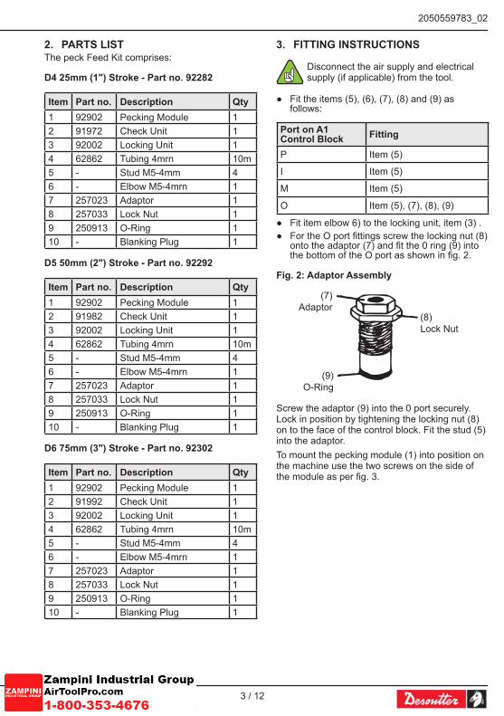
● Fit item elbow 6) to the locking unit, item (3) . ● For the O port fittings screw the locking nut (8)
onto the adaptor (7) and fit the 0 ring (9) into the bottom of the O port as shown in fig. 2.
Fig. 2: Adaptor Assembly
(8)Lock Nut
(7)Adaptor
(9)O-Ring
Screw the adaptor (9) into the 0 port securely. Lock in position by tightening the locking nut (8) on to the face of the control block. Fit the stud (5) into the adaptor.To mount the pecking module (1) into position on the machine use the two screws on the side of the module as per fig. 3.

2050559783_02
4 / 12 04/2013
Fig. 3: Mounting Dimensions for Pecking Module
73mm 83mm
125m
m
187m
m
7.5mm
Timingadjuster
Drill 2 holesØ5.5mm
● Measure and cut the tubing (4) and connect the ports on the control block and the locking unit (3) to the pecking module (1) with the tubing (as per fig. 1) ensuring the tubing is securely pushed into the fittings by pulling on them.
If fitting the peck kit to an AFD60 fit a signal inversion kit (part no. 104822) in the line from the M port on the control block to the M port on the pecking module (1).
3.1. Fitting the Locking unit ● Remove the tubing from the "RCU" port on the
pecking module (1). ● Connect the tube to an air supply and turn the
air on. This releases the lock. ● Slide the locking unit (3 ion to the check unit
(2) as per fig. 5. ● Secure in position by tightening the 3 grub
screws.
Fig. 5: Mounting the Locking Unit
3 Set screws
(2)Check unit
(3)Locking unit
● Switch off the air supply and disconnect the tube and reconnect to the "RCU" port on the pecking module (1).
3.2. Fitting the check unit and setting the depth on the tool
● To set the depth on the AFD (E) tools the drill bit should be as close as possible to the work to reduce the cycle time.
Fig. 5: Mounting the Locking Unit
65
4
9
2
3
87
1HCU
20mmmin.
hCu: hydaulic Check unit
● Depth is set by adjusting the gap between the adjusting screw (1) and the depth valve (2).
● The gap should be equal to the depth to be drilled, plus the distance of the drill bit above the work piece and any clearance through the other side (refer to the operating instructions for the tool service sheet).
● Slide the crosshead (3) to the correct position and locking it in that position using screw (4).
● Use the setting screw (8) to finally set the depth and lock in position with nut (9).
● To fit the check unit, slide the check unit into the crosshead (3), align the flat on the check unit with that in the crosshead and set the gap between the check unit rod (5) and the housing (6) to the distance required above the work piece.
● Lock the check unit in position with screw on crosshead.
● Unscrew the check unit adjuster (7) away from the check unit to adjust the control rate to a minimum.
● On the Al control block adjust the flow regulators , and as per the operating instructions for the tool.

2050559783_02
5 / 1204/2013
3.3. Connection to the Mains Air Supply ● Ensure that the air supply is turned off. ● The air supply to the pecking module should
be filtered (minimum of 30µm filter) and non-lubricated.
● A suitable supply can be found by connecting between the filter and the lubricator on the Desoutter range of filter, regulator, lubricator units.
● A minimum pressure of 6 bar (90psi) is required.
● Connect the port on the pecking module (1) to the air supply using an appropriate fitting.
● Ensure all fittings are secure prior to turning the air supply on.
3.4. Setting the Peck Adjustment ● To set the pecking timer rotate the adjuster to
the zero rate of pecking (see fig.6).
Fig. 6: Peck Adjustment
Rotate adjusterto vary thenumber of
pecks
● Set up a trial drilling operation and set the feed rate desire first.
● Then adjust the timer to give the required number of pecks dictated by the component material and the depth of drilling.

2050559783_02
6 / 12 04/2013
3.5. Connecting to an external Circuit
Emergencyretract
A1 Controlblock
Locking unit
To Forward RotationPort on Air Motor
Valve Mounted on Side ofTool - supplied with tool
For AFD625
Checkunit
DatumSignal
Start
Air in
PECKING MODULE
● The pecking unit can be controlled by using the following pneumatic signals:
Start Apply a pulse of air for 0.5-1 seconds into the “S” port on the pecking module (1).The tool will cycle automatically.
emergency retract
Apply a pulse of air for 0.5-1 seconds into the “ES” port on thepecking module (1).The tool will cycle return to datum automatically.
tool at Datum Signal
A positive continuous air signal is emitted from the “ICS” port when the tool is at the datum position.This signal decays when the tool is cycling. This port should be blanked off using the blanking plug (10) when not in use.

2050559783_02
7 / 1204/2013
4. StroKe Setting
Stro
ke
Stro
ke
Fine strokeadjustment
Rough strokeadjustment bysliding bracket
up and down
AutomaticRetract
Depth Stop
AutomaticRetract
Depth Stop

2050559783_02
8 / 12 04/2013
5. PeCK FeeD with interFaCe KitWhen using a peck feed kit in conjunction with an interlace kit (C1, C6, C10, C11, C12) additional parts will be required:
● (1) off: Manifold for Solenoid Valves ● (3) off: Male Stud
The solenoid valves are fitted to the manifold and not to the control block (see diagram).Control signals are exactly the same as per the conventional interface kits except that a signal will be received each time from the SW1 proximity switch when the tool returns to datum during the pecking cycle.
A1 Controlblock
HCU
Note:O port must have adaptor(257023),locknut (257033).O-Ring (110783)Fitted
Exhaust
Startsolenoidvalve
Seat opposing portusing M5 blankingplug from AFDcontrol block.
Emergencyretractsolenoid valve
DatumSignal
PECKING MODULE

2050559783_02
9 / 1204/2013
6. PeCK FeeD with PLC ControLIf the customer wishes to use a PLC to control the pecking cycle then the following control sequence and circuit should be used.
6.1. Sequence1. Start signal to PLC.2. Energise solenoid S1 for 0.5 seconds, tool
will feed forward.3. Set advance time using timer in PLC.4. Energise solenoid 52 for 0.5 seconds, after
set time, tool will retract to datum.5. Output from SW1 to PLC.6. Energise solenoid S1 for 0.5 seconds, tool
will advance to drilled depth due to HCU brake unit (92002) holding rod at previous depth position.
7. Set advance time using timer in PLC.8. Energise solenoid S2 for 0.5 seconds, afler
set time, tool will retract to datum.9. Repeat pecking until Signal from SW2
switch indicates that drill has reached depth.10. Energise solenoid S2 for 0.5 seconds, after
set time, tool will retract to datum and M port signal will shuttle vale across, releasing the brake and allowing the rod to extend ready for the next component.
Note: O port must have adaptor (257023), lock
nut (257033), O-Ring (110783) fitted
Locking Unit(92002)
HCU25mm50mm75mm Pilot operated valve
(91122)
11. PeCK FeeD Part nuMBerS
Part no. Description
92282 D4 25mm (1”) Peck Feed Kit
92292 D5 50mm (2”) Peck Feed Kit
92302 D6 75mm (3”) Peck Feed Kit
104822 M Port conversion kit
94982 HCU fitting kit for AFD60
94522 Manifold for solenoid valves
62392 Male stud
91972 Peck feed HCU 25mm (1”)
91982 Peck feed HCU 50mm (2”)
91992 Peck feed HCU 75mm (3”)
92002 HCU locking unit
91122 Pilot operated 5/2 valve

2050559783_02
10 / 12 04/2013
12. trouBLe ShootingThe start, emergency return and datum pneumatic signals are via the pecking module which in turn controls the pecking sequence through a full feature control block (see diagram).
Note: O port must have adaptor (257023), locknut (257033), O-Ring (110783) fitted
LockingUnit
HCU
Emergencyretract
DatumSignal
Start
PECKING MODULE
The ports are connected to the corresponding ports on the full feature control block.ICS is work cycle complete port (constant at end of cycle); S is Start Port; ES is Emergency Stop.An adaptor is fitted into the O port on the full feature block to blank it from the P port - this can be tested by depressing the end stop with the adaptor fitted and ensuring no air comes from the P port.For set up the feed rate required should be set on the HCU and the number of pecks by the timer within the control modules, larger time = less pecks.
1
1 timer
12.1. Check that the tool itself is operating correctly
(With peck feed still connected as above.) ● Depress Green Start Button: Tool should
advance strike depth stop and retract.
12.2. If Tool will not advance using Green Start Button
● Check Main Air is connected to main air inlet on tool.
● Air must be on and set at 90psi. ● Open advance rate regulating screw - tool
should advance.If not:
● Is there anything else connected to the tool that would be giving it a retract signal such as: Maintained Air signal into O or P port.
● If so check that the air line is not giving a constant air signal.
● If it is then remove this signal. ● It should be a pulse only for emergency
retract.
tool will advance but will not retract ● Check that the depth adjustment screw is
striking the depth stop. ● If it is not this could be due to Incorrect HCU
fitting. ● Check HCU is not acting as the hard stop.
WARNING! - this will damage the HCU leading to failure.
● Incorrect depth screw position. ● If depth adjustment screw is striking the depth
stop then check the flow control valves, these should be set as:
tool type AFDE200AFD205AFD215
Open To give fast retract
Adjust to Control Retract Rate
Adjust to Control Feed
AFD415 Adjust to Control Feed
Adjust to Control Retract Rate
Not Applicable
AFDE400/ 410AFDE600/ 610/ 620
Adjust to Control Feed
Adjust to Control Retract Rate
Not Applicable
AFDE400/ 410AFDE600/ 610/ 620With R port connected
Open To give fast retract
Adjust to Control Retract Rate
Adjust to Control Feed

2050559783_02
11 / 1204/2013
If depth adjustment screw is striking the depth stop and flow control valve are opened then check that no signals are still telling the unit to advance such as.Maintained Air signal into 1 port:
● If so check that the air line is not giving a constant air signal
● If it is then remove this signal - it should be a pulse only.
12.3. Check the signals from the A1 control block
● Check Main Air is connected to main air inlet on tool.
● Air must be on and set at 90psi. ● Remove the tubes from the P and O ports. ● Depress the end stop on the A1 control block. ● The adaptor and O-Ring fitted into the O port
should give an air signal from the O port but not the P port.
● If a signal comes from both ports then refit the adaptor and O-Ring to ensure it seals correctly.
● Refit the tubes to the O and P ports. ● With the tool in the datum/home/rest position
make sure a maintained signal comes from the M port on the A1 control block.
● Note carefully remove this tube.
12.4. Check operation of the peck feed control box
Remove the tube connections from the control box and follow the sequence below.
● Check Main Air is connected to main air inlet on peck control box.
● Air must be on and set at 50psi minimum - should be filtered but NOT lubricated Input a pulse of air into S start port on control box, and the M port simultaneously.
● Check that a pulse of air comes out of the 1 port on the control box. - This is the signal that would normally
advance the tool. ● After a certain time set by the timer in the
control box a constant air signal should come from the P port on the control box. - This is the signal that would normally
retract the tool when pecking. ● Input a pulse of air into the M port on the
control box. - This is the signal that would tell the box
that the AFD is home and ready to peck again.
● The constant signal from P will disappear and the above sequence should be repeated i.e. a pulse of air comes out of the 1 port on the control box and After a certain time set by the timer in the control box a constant air signal should come from the P port on the control box.
● Input a pulse of air into the 0 port on the control box. This is the signal that tells the AFD that the hole has been completed to depth.
● A pulse of air should come from the P port. ● Input a maintained signal into the M port. A
maintained signal should come from the ICS port on the control box and a constant signal from the HCU port on the control box.
● If the sequence above operates correctly than the control box is functioning correctly.
12.5. Check the connection of the Peck module to the a1 control block
● Having established that the tool functions correctly and the peck control box functions correctly - refit all pipe connections and try the peck cycle again.
● Check Main Air is connected to main air inlet on tool. Air must be on and set at 90psi.
● Check Main Air is connected to main air inlet on peck control box. Air must be on and set at 50psi minimum - are should be filtered but NOT lubricated.
● Make sure timer is set to a minimum. ● Make sure Hydraulic Control Unit is set to
required feed rate. ● Input a pulse signal to the S port on the
control box. ● Tool should advance and retract repeatedly. ● Increase the time set on the timer until the
number of pecks required is achieved.

www.desouttertools.com
More Than Productivity