pelamis: experience from concept to...
TRANSCRIPT

Phil. Trans. R. Soc. A (2012) 370, 365–380doi:10.1098/rsta.2011.0312
Pelamis: experience from concept to connectionBY RICHARD YEMM, DAVID PIZER*, CHRIS RETZLER AND ROSS HENDERSON
Pelamis Wave Power Ltd, 31 Bath Road, Edinburgh, UK
The development of the Pelamis wave energy converter from its conceptual origins to itscommercial deployment is reviewed. The early emphasis on designing for survivability andfavourable power absorption characteristics focused attention towards a self-referencedarticulated line-absorber in an attenuator orientation. A novel joint and control systemallow the machine to be actively tuned to provide a resonant response power amplificationin small and moderate seas. In severe seas, the machine is left in its default or naturalcondition, which is benign and non-resonant. Hydraulic rams at the joints provide theprimary power take-off with medium-term storage in high-pressure accumulators yieldingsmooth electricity generation. Land-based modular construction requiring minimalweather windows for rapid offshore installation is an essential engineering featurenecessary for viable commercialization. The second-generation Pelamis designs builtfor E.ON and ScottishPower Renewables are presented, and the scope for further costreduction and performance enhancements are explained.
Keywords: ocean; wave; power; renewable; energy
1. The Pelamis wave energy converter: fundamental principles
The Pelamis wave energy converter (WEC) is a floating offshore device thatconverts ocean wave energy into electricity. It is a semi-submerged, articulatedstructure, composed of multiple cylindrical sections linked by hinged joints.Motion of the hinged joints is restrained by hydraulic rams that pump fluidinto high-pressure accumulators, which smooth out the irregular wave bywave-absorbed power. Control of this pumping action allows absorption to bemaximized when waves are small and the response to be minimized in storms.Standard variable displacement hydraulic motors then draws a controlled flowfrom the accumulators to drive induction generators, the displacement of motorsis varied in response to the slowly varying system pressure to deliver steady,continuous electrical power output from each joint. All generation systems arehoused within the machines, and power is transmitted to the shore using standardsub-sea cables and equipment.
*Author for correspondence ([email protected]).
Electronic supplementary material is available at http://dx.doi.org/10.1098/rsta.2011.0312 or viahttp://rsta.royalsocietypublishing.org.
One contribution of 18 to a Theo Murphy Meeting Issue ‘The peaks and troughs of wave energy:the dreams and the reality’.
This journal is © 2011 The Royal Society365
on May 29, 2018http://rsta.royalsocietypublishing.org/Downloaded from
366 R. Yemm et al.
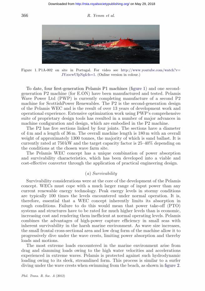
Figure 1. P1A-002 on site in Portugal. For video see http://www.youtube.com/watch?v=JYzocwUfpNg&fs=1. (Online version in colour.)
To date, four first-generation Pelamis P1 machines (figure 1) and one second-generation P2 machine (for E.ON) have been manufactured and tested. PelamisWave Power Ltd (PWP) is currently completing manufacture of a second P2machine for ScottishPower Renewables. The P2 is the second-generation designof the Pelamis WEC and is the result of over 13 years of development work andoperational experience. Extensive optimization work using PWP’s comprehensivesuite of proprietary design tools has resulted in a number of major advances inmachine configuration and design, which are embodied in the P2 machine.
The P2 has five sections linked by four joints. The sections have a diameterof 4 m and a length of 36 m. The overall machine length is 180 m with an overallweight of approximately 1300 tonnes, the majority of which is sand ballast. It iscurrently rated at 750 kW and the target capacity factor is 25–40% depending onthe conditions at the chosen wave farm site.
The Pelamis WEC concept has a unique combination of power absorptionand survivability characteristics, which has been developed into a viable andcost-effective converter through the application of practical engineering design.
(a) Survivability
Survivability considerations were at the core of the development of the Pelamisconcept. WECs must cope with a much larger range of input power than anycurrent renewable energy technology. Peak energy levels in stormy conditionsare typically 100 times the levels encountered under normal operation. It is,therefore, essential that a WEC concept inherently limits its absorption inrough conditions. Failure to do this would mean that power take-off (PTO)systems and structures have to be rated for much higher levels than is economic,increasing cost and rendering them inefficient at normal operating levels. Pelamiscombines the advantages of high-power capture efficiency in small seas withinherent survivability in the harsh marine environment. As wave size increases,the small frontal cross-sectional area and low drag form of the machine allow it toprogressively dive under the wave crests, limiting power absorption and therebyloads and motions.
The most extreme loads encountered in the marine environment arise fromdrag and slamming loads owing to the high water velocities and accelerationsexperienced in extreme waves. Pelamis is protected against such hydrodynamicloading owing to its sleek, streamlined form. This process is similar to a surferdiving under the wave crests when swimming from the beach, as shown in figure 2.
Phil. Trans. R. Soc. A (2012)
on May 29, 2018http://rsta.royalsocietypublishing.org/Downloaded from

Pelamis 367
Figure 2. Pelamis survivability: inherent limiting of loads and motions in extreme seas.(Online version in colour.)
Figure 3. Hydrodynamic power limiting.
Pelamis achieves power limiting as wave height increases by smoothly andprogressively submerging and emerging locally down the length of the machine,as depicted in figure 3. Once the cross section is locally submerged, the buoyancyforce applied by the wave does not grow. The drag and inertia loads continue,but these are inherently kept low owing to the streamlined shape and small localcross section.
Pelamis enjoys another operating and survivability advantage owing to the useof the wave curvature as the source of reaction and power absorption. Waves canonly reach a certain steepness before they naturally break and this inherentlylimits the effective curvature of an individual wave. It is advantageous to use thisself-limiting wave curvature rather than elevation as the driving mechanism asthis allows Pelamis to make better use of the force and stroke of its PTO ramsthan an equivalent heaving system, and there is a natural limit of joint anglesalong the machine. Conversely, a heaving system has to operate efficiently in1–2 m high seas, but withstand waves of up to 30 m in height. In practice, theheaving system cannot undergo such movements so must be locked down in largeseas or have a separate end stop system, both of which will have attendant loadsmuch higher than normal operating conditions.
(b) Power absorption
Most of the energy available over the year is in the form of waves that aresmall compared with those occurring during storms. It is, therefore, vital that aWEC is able to maximize absorption in such conditions for a given cost of build
Phil. Trans. R. Soc. A (2012)
on May 29, 2018http://rsta.royalsocietypublishing.org/Downloaded from

368 R. Yemm et al.
and operation. The crudest measure of cost is volume—this sets the basic size ofthe structural elements and has a direct influence on the average and maximumforces that the system is likely to see. These factors are two of the prime drivers ofcost in any engineered system. An effective wave energy absorber must make themost efficient use of volume to absorb the maximum power on average throughoutthe year.
Pelamis works on the ‘line-absorber’ principle, where waves are absorbed bya long structure extending perpendicular to the approaching wave fronts. Thismethod of absorption allows the highest power capture for a given volumeof machine without having to rely on fixed frames of reference with theirassociated extreme loads and sea-bed construction. This is the most fundamentalcompetitive advantage offered by Pelamis and is analogous to the advantageenjoyed by all modern wind turbines, which use lift to drive the rotor, ratherthan earlier designs that used drag.
In order to understand the nature and extent of this fundamental advantage,it is necessary to delve into some of the basic physics governing wave powerabsorption. WECs have theoretical limits on the amount of power they canabsorb from a given set of waves, similar to the Betz limit that applies to windturbines, or the Carnot limit that applies to thermal engines. Understandingthe nature and behaviour of these fundamental limits is vital to conceiving anddesigning an optimal engineering solution. In common with all real systems, thereare many factors that reduce the actual output of a WEC from the ultimateperformance limits. However, these fundamental limits are well established inscientific literature and represent the ultimate upper limit of performance, thusit is useful to examine the Pelamis limits with respect to other WEC concepts.
An often confusing aspect of wave energy is that a WEC can absorb moreenergy from the waves around it than is contained within its frontal width facingthe seas. This is because the machine is interacting with the entire wave fieldaround it not just with the waves that pass directly under the system. The energycapture of a WEC is often expressed as its ‘capture width’; this is the width ofincoming wave that has the same power as that being absorbed by the WEC.Owing to the mathematical relations that govern this aspect of WEC behaviour,the ultimate capture width of a given mode of absorption is a function of theincoming wavelength l. For this reason, the ultimate absorption potential of agiven configuration of machine is commonly expressed as a fraction of wavelength.
As for the Betz and Carnot limits, these fundamental capture width limits forWECs are based on an idealized system; for WECs, the assumption is infinitesimalwaves and responses. However, as proved in many areas, the performance of realphysical systems can approach the fundamental limits as their designs becomemore and more refined. For example, early wind mills typically had a peakperformance of less than 10–15% of the Betz limit [1] and an average performanceof much less. Through optimal design modern wind turbines can now deliver over70 per cent of the Betz limit [2] over much of their operating wind speed range.Similarly, Sir Frank Whittle’s first gas turbine achieved an overall efficiency ofless than 10 per cent; modern aircraft gas turbines are nearly four times moreeffective and combined cycle gas power plants can achieve over 50 per cent.
There are several categorizations of the large variety of proposed WEC designs(e.g. [3]). In general, wave energy absorbers can be thought of as wave-makers,with their motion-radiating waves (like a stone cast into a pond that radiates
Phil. Trans. R. Soc. A (2012)
on May 29, 2018http://rsta.royalsocietypublishing.org/Downloaded from
Pelamis 369
(a) (b)
(c) (d)
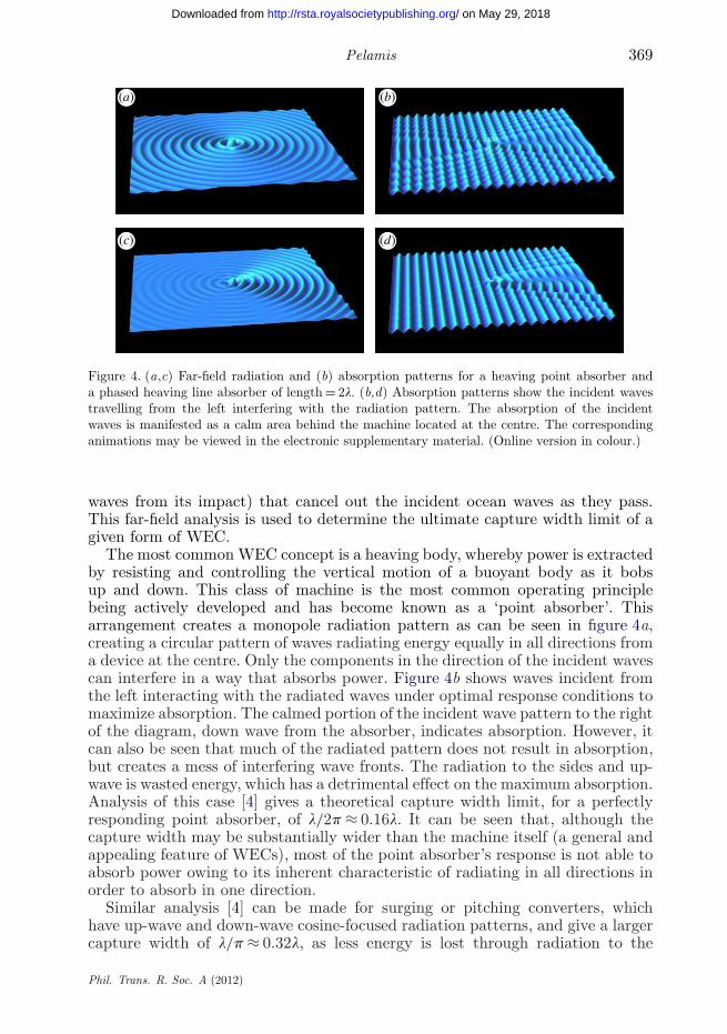
Figure 4. (a,c) Far-field radiation and (b) absorption patterns for a heaving point absorber anda phased heaving line absorber of length = 2l. (b,d) Absorption patterns show the incident wavestravelling from the left interfering with the radiation pattern. The absorption of the incidentwaves is manifested as a calm area behind the machine located at the centre. The correspondinganimations may be viewed in the electronic supplementary material. (Online version in colour.)
waves from its impact) that cancel out the incident ocean waves as they pass.This far-field analysis is used to determine the ultimate capture width limit of agiven form of WEC.
The most common WEC concept is a heaving body, whereby power is extractedby resisting and controlling the vertical motion of a buoyant body as it bobsup and down. This class of machine is the most common operating principlebeing actively developed and has become known as a ‘point absorber’. Thisarrangement creates a monopole radiation pattern as can be seen in figure 4a,creating a circular pattern of waves radiating energy equally in all directions froma device at the centre. Only the components in the direction of the incident wavescan interfere in a way that absorbs power. Figure 4b shows waves incident fromthe left interacting with the radiated waves under optimal response conditions tomaximize absorption. The calmed portion of the incident wave pattern to the rightof the diagram, down wave from the absorber, indicates absorption. However, itcan also be seen that much of the radiated pattern does not result in absorption,but creates a mess of interfering wave fronts. The radiation to the sides and up-wave is wasted energy, which has a detrimental effect on the maximum absorption.Analysis of this case [4] gives a theoretical capture width limit, for a perfectlyresponding point absorber, of l/2p ≈ 0.16l. It can be seen that, although thecapture width may be substantially wider than the machine itself (a general andappealing feature of WECs), most of the point absorber’s response is not able toabsorb power owing to its inherent characteristic of radiating in all directions inorder to absorb in one direction.
Similar analysis [4] can be made for surging or pitching converters, whichhave up-wave and down-wave cosine-focused radiation patterns, and give a largercapture width of l/p ≈ 0.32l, as less energy is lost through radiation to the
Phil. Trans. R. Soc. A (2012)
on May 29, 2018http://rsta.royalsocietypublishing.org/Downloaded from

370 R. Yemm et al.
Table 1. Capture width limits of different types of wave energy converter.
mode of absorption theoretical capture width
heaving body l/2p ≈ 0.16l
surging or pitching l/p ≈ 0.32l
heaving-and-surging or heaving-and-pitching 3l/2p ≈ 0.48l
line absorber length = l [5,6] 0.50l
line absorber length = 2l [5] 0.73l
side. An appropriate combination of heave and surge can yield a down-wave-focused radiation pattern without the up-wave component and a capture widthof 3l/2p ≈ 0.48l is attained, as there is no energy loss through up-wave radiation.
The theoretical line absorber limits, as applies to the Pelamis, are a functionof the length of the machine. As depicted in figure 4c, the radiation pattern froma line absorber of length equal to twice the wavelength provides a highly focusedradiation pattern with little losses in other directions, and when interfering withthe incident wave (figure 4d) provides cancellation (and hence absorption) of theincident wave down wave from the absorber. The theoretical line absorber limitfor this case rises to 0.73l [5], nearly five times that of a heaving buoy.
These key results are summarized in table 1.
(c) Engineering embodiment
(i) Self-contained reaction forces
All WECs must act against the force of the waves to absorb the energy.Creating such forces requires something for the PTO mechanism to pushagainst—a source of reaction. Unlike the vast majority of WEC concepts thatreact against the sea-bed, a large inertia component or a submerged damper plate,Pelamis reacts against its own buoyancy. This property of ‘self-referencing’ meansthat the buoyancy forces caused by the waves are reacted against by buoyancyforces elsewhere on the machine itself. This has the following advantages:
— it allows structural and mooring loads to be inherently self-limiting inextreme conditions;
— it avoids the significant costs and lack of flexibility associated with theprovision of an external source of reaction;
— the attendant small mooring loads allow the self-contained system to beeasily taken on and off site using small cost-effective vessels; and
— the lightweight moorings are easily deployed without major on-site‘construction’ using specialist vessels.
(ii) Selectable resonant response to wave conditions
Many WEC concepts make use of resonance to increase power capture whenseas are small. However, systems that hard-wire in a resonant condition will leadto undesirably large amplified responses in storm conditions.
Phil. Trans. R. Soc. A (2012)
on May 29, 2018http://rsta.royalsocietypublishing.org/Downloaded from

Pelamis 371
response
responsepitch axis
yaw axis
11.
2.
Pelamis in non-resonant condition—restraint equal about the pitch andyaw axes. Response vertical andnon-resonantPelamis in resonant condition—restraint much greater about pitch axisthan yaw. Response inclined andresonant
2
Figure 5. Schematic of Pelamis selectable–tunable joint response. (Online version in colour.)
Pelamis uses the concept of selectable–tunable resonant response (figure 5).The joints are actively controlled to induce a cross-coupled resonant response onlywhen desired; the default or natural condition is a benign non-resonant responseinherently capable of dealing with extreme conditions. Note that, while resonancecan, in theory, be achieved purely through a sophisticated PTO system in anyWEC concept by adjusting the ‘internal impedance’ that the PTO applies, the useof cross-coupled resonance in the Pelamis avoids the need for excessive reactivepower transfer or complicated latching systems. Instead, the simple ratio betweenpure damping restraints (i.e. zero reactive power) applied at each of the coupledaxes effectively induces a change to the ‘external impedance’ of the machine byinducing an inclined response. The angle of the inclined response determines thenatural period as dictated by the fraction of vertical hydrostatic stiffness, whichbalances with the inertia. This effect is apparent in internal gravity waves, inwhich the frequency of excitation determines the angle of inclination of freelyoscillating the fluid particles. This capability to match machine response to thewaves in a given sea-state is similar in concept to the now industry standardvariable speed rotors and variable pitch blades on wind turbines, where theturbine speed and blade angle are continuously adjusted to optimize energycapture as the wind speed changes and avoid stress when the wind speed grows.
(iii) Smooth power
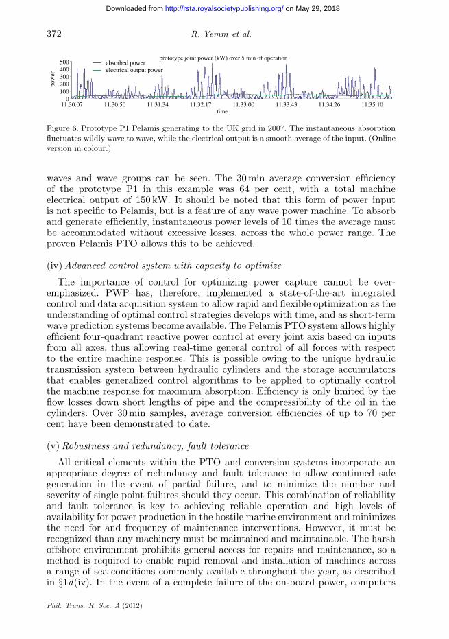
As individual waves and wave groups pass a Pelamis WEC, the input powerto the individual joints is highly variable in nature, with power at a joint goingfrom zero to a peak and back again every few seconds. Standard industrial high-pressure accumulators collect the variable input power and allow the generatorsto run from a slowly varying pressure supply, while coping efficiently with thevery high instantaneous power levels required in individual waves. This meansthat all the electrical generation and transmission equipment is only rated forthe average of the power available rather than for peaks. Figure 6 shows anexample power record for the first joint of the prototype P1 machine duringtests at the European Marine Energy Centre (EMEC) in 2007, and shows theinstantaneous absorbed power along with the smooth electrical output power atthat joint. The time window shown is 5 min, so the effects of both individual
Phil. Trans. R. Soc. A (2012)
on May 29, 2018http://rsta.royalsocietypublishing.org/Downloaded from
372 R. Yemm et al.
500400300
pow
er
200100
011.30.07 11.30.50 11.31.34 11.32.17 11.33.00
time11.33.43 11.34.26 11.35.10
absorbed powerprototype joint power (kW) over 5 min of operation
electrical output power
Figure 6. Prototype P1 Pelamis generating to the UK grid in 2007. The instantaneous absorptionfluctuates wildly wave to wave, while the electrical output is a smooth average of the input. (Onlineversion in colour.)
waves and wave groups can be seen. The 30 min average conversion efficiencyof the prototype P1 in this example was 64 per cent, with a total machineelectrical output of 150 kW. It should be noted that this form of power inputis not specific to Pelamis, but is a feature of any wave power machine. To absorband generate efficiently, instantaneous power levels of 10 times the average mustbe accommodated without excessive losses, across the whole power range. Theproven Pelamis PTO allows this to be achieved.
(iv) Advanced control system with capacity to optimize
The importance of control for optimizing power capture cannot be over-emphasized. PWP has, therefore, implemented a state-of-the-art integratedcontrol and data acquisition system to allow rapid and flexible optimization as theunderstanding of optimal control strategies develops with time, and as short-termwave prediction systems become available. The Pelamis PTO system allows highlyefficient four-quadrant reactive power control at every joint axis based on inputsfrom all axes, thus allowing real-time general control of all forces with respectto the entire machine response. This is possible owing to the unique hydraulictransmission system between hydraulic cylinders and the storage accumulatorsthat enables generalized control algorithms to be applied to optimally controlthe machine response for maximum absorption. Efficiency is only limited by theflow losses down short lengths of pipe and the compressibility of the oil in thecylinders. Over 30 min samples, average conversion efficiencies of up to 70 percent have been demonstrated to date.
(v) Robustness and redundancy, fault tolerance
All critical elements within the PTO and conversion systems incorporate anappropriate degree of redundancy and fault tolerance to allow continued safegeneration in the event of partial failure, and to minimize the number andseverity of single point failures should they occur. This combination of reliabilityand fault tolerance is key to achieving reliable operation and high levels ofavailability for power production in the hostile marine environment and minimizesthe need for and frequency of maintenance interventions. However, it must berecognized than any machinery must be maintained and maintainable. The harshoffshore environment prohibits general access for repairs and maintenance, so amethod is required to enable rapid removal and installation of machines acrossa range of sea conditions commonly available throughout the year, as describedin §1d(iv). In the event of a complete failure of the on-board power, computers
Phil. Trans. R. Soc. A (2012)
on May 29, 2018http://rsta.royalsocietypublishing.org/Downloaded from

Pelamis 373
or communication systems (a worst case scenario), a purely mechanical fail-safesystem (normally held-off) takes over. If power output is overly compromised bycumulative faults, or a fault is deemed potentially damaging to other systems,then the machine can be quickly and safely removed in less than an hour withminimal vessel requirements and reinstalled again as easily. The allowable weatherwindows for such operations mean that they can be conducted with acceptablewaiting periods throughout the year, albeit with some inevitable compromiseduring the winter.
(vi) Uses proven technologies
The Pelamis is an assembly of existing industrial components into anovel configuration. The machine requires no fundamentally new engineeredcomponent. The mechanical, electrical and hydraulics equipment have a proventrack record in other applications, particularly in the offshore oil and gas sector,but also in construction vehicles and other generation technologies. The mainstructural elements are designed and fabricated using standard offshore andmarine industry practices, thus there are many supply chain options for muchof the machine, allowing lower cost competitive sourcing and flexibility in themanufacturing process.
(d) Construction and operation and maintenance strategy
(i) Off-site machine build and commissioning
All main components are readily road or sea transportable, and manufacturingand commissioning activities are carried out in a controlled factory environmentreducing time, cost and weather dependence and allowing concentration ofinvestment and resources. No offshore construction or assembly of the machine isrequired. Many proposed WEC systems require very large individual structures,which would need to be manufactured in a shipyard or offshore fabrication yardwith attendant high overheads and reduction in flexibility (figure 7).
(ii) Modular assembly for efficient manufacture
The Pelamis is made up of a number of similar sections, each of which containsan identical joint assembly and PTO equipment. This allows the high-technologygeneration systems of each joint to be consolidated into a compact ‘skid’ that canbe assembled and factory tested independently and on an open frame prior toposting into an end structure for attachment to the main tube section (figure 8).This method of assembly keeps the time that large structural components arepresent in the assembly area to a minimum, reducing factory size and liftingrequirements considerably. A further benefit is that the entire commissioningjoint PTO system can be shipped in a standard container and is therefore readilytransportable to final assembly sites around the world.
(iii) Generally deployable and scalable
The Pelamis moorings, mid-water electrical interconnection cabling and rapidmachine connection and disconnection system will allow large wave farms to beinstalled rapidly and cost-effectively using non-specialist vessels and equipment
Phil. Trans. R. Soc. A (2012)
on May 29, 2018http://rsta.royalsocietypublishing.org/Downloaded from

374 R. Yemm et al.
Figure 7. Modular construction in Leith, Edinburgh, UK, of P2 for ScottishPower Renewables,2011. (Online version in colour.)
Figure 8. P2 skids in production. (Online version in colour.)
and to subsequently be expanded in a modular fashion. Current estimates arethat a full mooring spread of chains and anchors can be installed in less than24 h using existing anchor handling vessels commonplace in the offshore industry.There is no major offshore construction work or piling on-site and, owing to thedeep-water location, the main cable runs do not typically need to be trenchedonce clear of the beach and foreshore.
Phil. Trans. R. Soc. A (2012)
on May 29, 2018http://rsta.royalsocietypublishing.org/Downloaded from

Pelamis 375
(iv) No machine maintenance offshore: minimized weather-dependent work
PWP is firmly of the view that the aggressive offshore environment isincompatible with any requirement for access to the machine while on-site. Evenif some tasks were practical, health and safety requirements would severely limitthe conditions in which any access could be gained.
It is far preferable to bring the machine to a suitable maintenance facilityfor complete availability of all tools, spares and skills, and to remove weatherfrom the equation while complex procedures are executed. For this reason, thePelamis has a proven rapid, weather-tolerant installation and removal systemto allow maintenance to be conducted off-site, in a safe and properly supportedenvironment. The system uses small, low-cost vessels to position the machine overthe mooring system before an automated ‘hands-free’ winch system mechanicallyand electrically connects the machine to the sub-sea infrastructure.
The whole process takes less than 1 h and, owing to the hands-free nature andlack of manned access to the machine, it can be completed in rough conditions.It is immediately available to generate once installed. Removal of the machine iseven more straightforward and can be completed in a matter of minutes in evenrougher conditions. As Pelamis has a long, thin shape, it can be easily towedby small vessels, and its shallow draft requires only a few metres of water depthto enter sheltered facilities. A rapid installation cycle using conventional vesselsand procedures is a major advantage over other marine energy and offshore windtechnologies.
2. Pelamis wave energy converter: development path
(a) Design tools and processes
PWP has progressively developed a comprehensive and sophisticated set ofin-house design tools and processes that are used to establish and optimizemachine response and performance across all conditions and provide all requireddesign data such as motions, loads, fatigue and wear cycles. These tools enableimprovements to be made in machine designs from the fundamental geometrythrough to details of the PTO systems, and the creation and implementation ofimproved control algorithms for increased energy yield. The design tools andprocesses have been continuously reviewed and refined through feedback andexperience of each of the machine design exercises and from operational test data.
(i) PWP’s simulation package: ‘virtual machine’
PWP’s suite of simulation programs has been continuously developed by PWPover the lifetime of the project and currently represents the state of the artin the modelling of wave energy conversion. The programs use a rigid bodyrepresentation of the machine sections with a variety of formulations adaptableto the task at hand with respect to the computational effort and levels ofdetail required (table 2). The formulations include nonlinear two-dimensionalhydrodynamics, three-dimensional multi-body diffraction and radiation, finite-element mooring models and fully detailed PTO and control. Linear formulationsin both the time domain and frequency domain allow much more rapidcomputation than nonlinear models; this is very useful for design scoping
Phil. Trans. R. Soc. A (2012)
on May 29, 2018http://rsta.royalsocietypublishing.org/Downloaded from
376 R. Yemm et al.
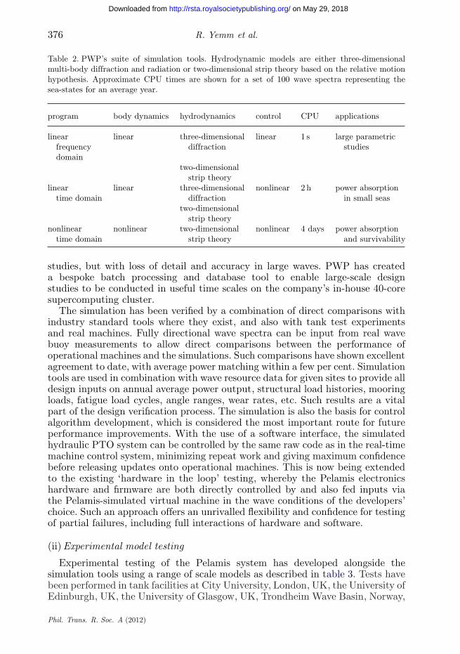
Table 2. PWP’s suite of simulation tools. Hydrodynamic models are either three-dimensionalmulti-body diffraction and radiation or two-dimensional strip theory based on the relative motionhypothesis. Approximate CPU times are shown for a set of 100 wave spectra representing thesea-states for an average year.
program body dynamics hydrodynamics control CPU applications
linear linear three-dimensional linear 1 s large parametricfrequency diffraction studiesdomain
two-dimensionalstrip theory
linear linear three-dimensional nonlinear 2 h power absorptiontime domain diffraction in small seas
two-dimensionalstrip theory
nonlinear nonlinear two-dimensional nonlinear 4 days power absorptiontime domain strip theory and survivability
studies, but with loss of detail and accuracy in large waves. PWP has createda bespoke batch processing and database tool to enable large-scale designstudies to be conducted in useful time scales on the company’s in-house 40-coresupercomputing cluster.
The simulation has been verified by a combination of direct comparisons withindustry standard tools where they exist, and also with tank test experimentsand real machines. Fully directional wave spectra can be input from real wavebuoy measurements to allow direct comparisons between the performance ofoperational machines and the simulations. Such comparisons have shown excellentagreement to date, with average power matching within a few per cent. Simulationtools are used in combination with wave resource data for given sites to provide alldesign inputs on annual average power output, structural load histories, mooringloads, fatigue load cycles, angle ranges, wear rates, etc. Such results are a vitalpart of the design verification process. The simulation is also the basis for controlalgorithm development, which is considered the most important route for futureperformance improvements. With the use of a software interface, the simulatedhydraulic PTO system can be controlled by the same raw code as in the real-timemachine control system, minimizing repeat work and giving maximum confidencebefore releasing updates onto operational machines. This is now being extendedto the existing ‘hardware in the loop’ testing, whereby the Pelamis electronicshardware and firmware are both directly controlled by and also fed inputs viathe Pelamis-simulated virtual machine in the wave conditions of the developers’choice. Such an approach offers an unrivalled flexibility and confidence for testingof partial failures, including full interactions of hardware and software.
(ii) Experimental model testing
Experimental testing of the Pelamis system has developed alongside thesimulation tools using a range of scale models as described in table 3. Tests havebeen performed in tank facilities at City University, London, UK, the University ofEdinburgh, UK, the University of Glasgow, UK, Trondheim Wave Basin, Norway,
Phil. Trans. R. Soc. A (2012)
on May 29, 2018http://rsta.royalsocietypublishing.org/Downloaded from

Pelamis 377
(a)time = 149.9
(b)
Figure 9. Snap-shot comparison between the video of the 21st scale model test in Nantes,France (b) and the corresponding animation of the nonlinear numerical simulation (a).For video/animation comparison, see http://www.youtube.com/watch?v=_f_nKSLLeXw&fs=1.(Online version in colour.)
Table 3. Experimental model testing over the duration of the project.
scale date control test site application
1:80 1998 none Edinburgh proof-of-concept survivability1:35 1998 water piston Edinburgh proof-of-concept absorption1:20 2000 water piston Edinburgh, City, Trondheim absorption and survivability1:33 2000–2001 electric motor Glasgow absorption and survivability1:7 2001–2002 hydraulic Firth of Forth, Nantes real-time control1:20 2003–2005 electric motor Trondheim, Nantes absorption and survivability1:21 2007–2011 electric motor Nantes absorption and survivability
and at Ecole Centrale de Nantes, France, over a range of model scales rangingfrom 1:80 to 1:7. The model tests have provided early proof of concept, ongoingverification of the developing numerical models, testing implementations of thereal-time control systems and survivability verification for the most extreme sea-state conditions. The 1:21 scale model in current use is constructed in a modularform enabling variations in section geometry and configurations to be modelled(figure 9).
(b) The P2 Pelamis
This operational experience of the P1 and the use of state-of-the-art proprietarydesign tools directly led to the P2 design programme culminating in:
— new joint configuration allowing for more efficient use of structure, drivetrain components and higher degree of modularity, making the machineeasier to assemble and maintain (figure 10);
Phil. Trans. R. Soc. A (2012)
on May 29, 2018http://rsta.royalsocietypublishing.org/Downloaded from

378 R. Yemm et al.
Figure 10. Cutaways of the P2 joint and power take-off (PTO) system, allowing the four hydrauliccylinders of each joint to act about 2 d.f. simultaneously. The modular PTO ‘skid’ (seen in assemblyin figure 8) incorporating the generation system and low-pressure fluid reservoirs is visible betweenthe actuators. The high-pressure accumulators used to store energy between waves and wave groupsare also visible. (Online version in colour.)
10095
effi
cien
cy (
%) 90
858075706560
0 20 40 60 80
electrical output power (kW)
100 120
P2 P1A
140 160
Figure 11. The measured conversion efficiency of the motor-generator sets that convert the highpressure (250 bar) in the accumulators into electricity. The improvement from the previous designsapplied on the P1 machines to the current P2 design can be seen in terms of both absolute efficiencyand range. The total combined conversion efficiency (from wave to wire) is typically approximately70% for the P2. (Online version in colour.)
— substantially larger joint angle range, increasing power capture andsurvivability margin;
— higher conversion efficiency of 20–30% and substantially lower cut in waveheight (nominal 1 m Hs versus 2 m Hs) to keep absorbing in smaller seascommon in summer; and
— 35 per cent higher yield from the additional cylindrical machine sectionand associated length, along with a 15 per cent increase in diameter.
Although all the P2 fundamental principles and design philosophy are the same asthe P1, the above improvements result in more than double the target energy yieldand around 50 per cent higher yield per tonne than the P1 machines (figure 11).
(c) Roadmap towards cost competitiveness
For renewable technologies to be competitive with conventional power-generating technologies in an environment without subsidies, a rigorous andwell-worn path to cost reduction is being followed. The typical cost curve for
Phil. Trans. R. Soc. A (2012)
on May 29, 2018http://rsta.royalsocietypublishing.org/Downloaded from

Pelamis 379
cost
of
ener
gy
conceptual phase
normal learning curve
cumulative capacity installed
extended learningrapid
learning
first-of-a-kind PWP currentfocus
offshore windonshore wind gas turbines
Figure 12. The typical cost curve for a technology. (Online version in colour.)
a technology (figure 12) is characterized by cost growth during the conceptualand research and development phase as the real nature of the problem and itsfirst-pass solution are understood and realized. This culminates in a true first-of-a-kind system, with all fundamental technical challenges encountered and resolved.From that point onwards, costs fall rapidly as the performance of the technologyimproves, conservatism in the design to control risks is progressively reduced andeconomies of scale in production are realized.
PWP has designed, built, installed and operated five full-scale machines, witha sixth due to be installed later this year; this experience gives PWP a detailedunderstanding of the costs associated with manufacturing and deploying waveenergy technology. The P1 machines were all development units to prove thefundamental concepts and test the technology elements, and to establish designdrivers for future commercial machines.
The P2 machine is the culmination of this process and represents PWP’s pre-commercial prototype for testing with customers in a commercial context. The keytarget for these machines is to demonstrate that the first 10 MW mini-farms willhave acceptable execution risk and will deliver an acceptable return on investmentin the Renewable Obligation Certificate (ROC) market currently available withinScotland, and potentially to be made available throughout the UK.
E.ON and ScottishPower Renewables will test the P2 machines at EMECover the next 3 years. Both companies have ambitions to install larger farmsof machines at sites on the west coast of Orkney, UK. Both have been successfulin securing exclusive rights to develop separate 50 MW wave farms using Pelamistechnology in the UK’s first wave and tidal leasing round held by the CrownEstates in 2010. At the same time, PWP itself secured the exclusive right todevelop an up to 50 MW wave farm at Farr Point on the north coast of the UK.The specific wave sites awarded by the Crown Estate are highlighted in figure 13;the sites include 250 MW of unspecified technology developments.
In addition to these sites, PWP is developing two further sites in UK waters.The first, off the coast of Shetland, is being developed as a joint venture withSwedish utility Vattenfall. The joint venture company, Aegir Wave Power, was
Phil. Trans. R. Soc. A (2012)
on May 29, 2018http://rsta.royalsocietypublishing.org/Downloaded from

380 R. Yemm et al.
developer technology
Pelamis 50 MW Armadale
Marwick Head
Marwick HeadPelamis P2
50 MWWest Orkney middle southPelamis P2
50 MWWest Orkney south
unspecified50 MW
West Orkney south
West Orkney middle south
50 MW
50 MW
50 MW
200 MW
200 MW
EMEC
Lyness
Armadale
ArmadalePelamis P2
50 MW
Dounreay
33 kV line132 kV line
transmission line
Costa Head
Costa Headunspecified
200 MW
Brough Head Brough HeadOyster
200 MW
Pelamis
Pelamis
unspecified
unspecified
Oyster
capacity site
Ocean Power Delivery*
Scottish Power
Scottish and Southern Energy
JV SSE/Aquamarine
Note: excludes tidal lease options *subsidiary of PWP
E.ON
E.ON
denotes wave site using PWP technology
Figure 13. Wave sites awarded by The Crown Estate in the UK’s first wave and tidal leasinground in 2010. (Online version in colour.)
set up in 2009 and is developing a 10 MW site off the southwest coast of Shetland,UK. PWP is also independently developing a site off the west coast of Lewis inthe Outer Hebrides, UK, for a project of up to 20 MW.
References
1 British Wind Energy Association. 1982 Wind energy for eighties. Stevenage, UK: PeterPeregrinus.
2 Department for Business, Innovation and Skills. 2001 Efficiency and performance. WindEnergy Fact Sheet 14. London, UK: Department for Business, Innovation and Skills. Seehttp://www.berr.gov.uk/files/file17821.pdf
3 Commission of the European Communities. 2010 Equitable testing and evaluation ofmarine energy extraction devices in terms of performance, cost and environmental impact.Deliverable D5.2 device classification template. EquiMar. See http://www.equimar.org/equimar-project-deliverables.html
4 Newman, J. N. 1976 The interaction of stationary vessels with regular waves. In Proc. of the 11thSymp. on Naval Hydrodynamics, London, UK, 28 March–2 April 1976 (eds R. E. D. Bishop,A. G. Parkinson & W. G. Price) pp. 491–501. London, UK: Mechanical EngineeringPublications Limited.
5 Farley, F. J. M. 1982 Wave energy conversion by flexible resonant rafts. Appl. Ocean Res. 4,57–63. (doi:10.1016/S0141-1187(82)80022-9)
6 Rainey, R. C. T. 2001 The Pelamis wave energy converter: it may be jolly good in practice,but will it work in theory? In Proc. of the 16th Int. Workshop on Water Waves and FloatingBodies, Hiroshima, Japan, 22–25 April 2001. See http://www.iwwwfb.org/Workshops/16.htm
Phil. Trans. R. Soc. A (2012)
on May 29, 2018http://rsta.royalsocietypublishing.org/Downloaded from