performance improvement of neural network based rls channel estimators in mimo-ofdm systems
TRANSCRIPT
Al-KhwarizmiEngineering!!!
JournalAl-Khwarizmi Engineering Journal, Vol. 7, No. 2, PP 36 - 46 (2011)
Performance Improvement of Neural Network Based RLS Channel Estimators in MIMO-OFDM Systems
Alaa Abdulameer HassanDepartment of Mechatronics Engineering/ Al-Khawarizmi College of Engineering/ University of Baghdad
E-mail: [email protected]
(Received 14 Febrewary 2011; accepted 12 May 2011)
Abstract
The objective of this study was tointroduce a recursive least squares (RLS) parameter estimatorenhanced by using a neural network (NN) to facilitate the computing of a bit error rate (BER) (error reduction) during channels estimation of a multiple input-multiple output orthogonal frequency division multiplexing (MIMO-OFDM) system over a Rayleigh multipath fading channel.Recursive least square is an efficient approach to neural network training:first, the neural network estimator learns to adapt to the channel variations then it estimates the channel frequency response. Simulation results show that the proposed method has better performance compared to the conventional methods least square (LS) and the original RLS and it is more robust at high speed mobility.
Keywords: MIMO-OFDM, RLS, NN, BER, SNR, channel, estimation.
1. Introduction
The multiple-input-multiple-output orthogonal frequency division multiplexing (MIMO-OFDM) technology has been considered as a strong candidate for the next generation wireless communication systems [1]. Using multiple transmit as well as receive antennas, a MIMO-OFDM system gives a high data rate without increasing the total transmission power or bandwidth compared to a single antenna system. Recently, research suggests that the implementation of MIMO-OFDM is more efficient because of the straightforward matrix algebra invoked for processing the MIMO-OFDM signals. It thus seems to be an attractive solution for future broadband wireless systems [2].
The arrangement of multiple antennas at the transition end and reception end results increase in the diversity gain refers the quality of signal and multiplexing gain refers the transmission capacity [3, 4, 5].
Further, the frequency-selective problem that exists in a conventional wireless system can be well solved by the OFDM technique in the
MIMO-OFDM system. On the other hand, the performance of MIMO-OFDM systems depends largely upon the availability of the knowledge of the channel. However, MIMO relies upon the knowledge of channelstate information (CSI) at the receiver for data detection and decoding. It has been proved that when the channel is Rayleigh fading and perfectly known to the receiver, the capacity of a MIMO–OFDM system grows linearly with the number of transmit or receive antennas, whichever is less [1, 6]. Therefore, an accurate estimation of the wireless channel is of crucial importance to MIMO–OFDM systems.
Recent works tackled theperformance assessment (both through simulation and measurements) of MIMO-OFDM systems in the presence of practicalimpairments, such as synchronization and channel estimation errors [7].
The major challenge faced in MIMO-OFDM systems is howto obtain the channel state information accurately and promptlyfor coherent detection of information symbols. The channel stateinformation can be obtained through trainingbased, blind and semiblind channel estimation. The blind channel estimation iscarried
This page was created using Nitro PDF trial software.
To purchase, go to http://www.nitropdf.com/

Alaa Abdulameer Hassan Al-Khwarizmi Engineering Journal, Vol. 7, No. 2, PP 36 - 46 (2011)
37
out by evaluating the statistical information of thechannel and certain properties of the transmitted signals [3].
Blind Channel Estimation has its advantage in that it has nooverhead loss; it is only applicable to slowly time-varyingchannels due to its need for a long data record. In training basedchannel estimation algorithms, training symbols or pilot tonesthat are known a priori to the receiver, are multiplexed alongwith the data stream for channel estimation. Semiblindchannel technique is hybrid of blind and training technique,utilizing pilots and other natural constraints to perform channelestimation [3].
The training basedmethods employ known training signals to render accuratechannel estimation. One of the most efficient trainingbasedmethods is the least squares (LS) algorithm. When thefull or partial information of the channel correlation is known, abetter channel estimation performance can be achieved via someminimum mean square error (MMSE) methods[1].
In this work, we propose a channel estimation algorithmfor MIMO-OFDM systems by employing backpropagationmultilayer neural networks to improve the performance ofa standard recursive least squares (RLS) strategy in a Rayleigh fading channel. The RLS approachis an efficient semi-second-order training that leads toa faster convergence compared with the first-order approaches such as backpropagation (BP) algorithms [8]; and is (RLS) widely used for parameter estimation because of its simplicity and fast rates of convergence.
The model used by the standard RLSalgorithm is based on Multi-LayeredPerceptrons (MLP). This type of neural network isknown as a supervised network because it requires adesired output in order to learn model.
The method described in this paper, however, uses a neural network to learn the parameter updating process of a standard RLS algorithm and then to relate the parameters so obtained to the operating conditions. To achieve this, the operating conditions are used as input patterns to a neural network and the neural network is then trained by comparing the parameters obtained from RLS algorithms with those from the neural network. This method combines the advantages of the simplicity and speed of convergence of RLSalgorithms with the ability of neural networks tolearn any complex process to any desired accuracy.
Also, further enhancement of performance can be achieved through maximum diversity Space Time Block Coding (STBC) and Maximum Likelihood (ML) Detection at transmission and reception ends respectively. STBCs have theability to greatly reduce the bit error rate (BER) or increase the data rate, and have gained much attention as they are able to integrate the techniques of spatial diversity and channel coding, and can provide significant capacity gains in MIMO (OFDM/CDMA) systems.
The rest of the paper is organized as follows. In the following section the MIMO-OFDM with STBC system model is described. The next sectionpresents a general method to channel estimation worked out on RLS approach and describes the chosen NN architecture and its application on RLS estimation. Then, some simulation results and discussionsare given and finally, the least section concludes the paper.
2. System Description
2.1. MIMO-OFDM System
The configuration of multiple antennas can be divided intothree categories [10]: (1) MISO (multiple input single output): uses more than one antenna at the transmitter and only oneat the receiver; (2) SIMO (single input multiple output):uses one transmitting antenna and more than one receivingantenna; and (3) MIMO: uses more than one antenna at thetransmitter and more than one at the receiver.
By using more than one transmit/receive antenna, multiplechannels are employed between each pair of transmit andreceive antennas. The transmitted signalwill travel through different channels to arrive at thereceiver side. If one of the channels is sufficiently strong,the receiver will be able to recover the transmitted signal.
If different channels are independent, then the probabilityof all channels failing is very small [10].
We consider a MIMO wireless communication systememploying Nt transmit and Nr receive antennas (figure(1)), hence, thecorresponding MIMO wireless communication channel is constitutedby (Nr×Nt) propagation links. Furthermore, each ofthe corresponding (Nr×Nt)single-input single-output (SISO) propagation links comprises multiple statistically independentcomponents, termed as paths [3, 11, 12, 13, 14, 15].
This page was created using Nitro PDF trial software.
To purchase, go to http://www.nitropdf.com/

This page was created using Nitro PDF trial software.
To purchase, go to http://www.nitropdf.com/

Alaa Abdulameer Hassan Al-Khwarizmi Engineering Journal, Vol. 7, No. 2, PP 36 - 46 (2011)
Modulation DemodulationMIMOEncoder
MIMODecoder
OFDM Tx
OFDM Tx
OFDM Tx
OFDM Rx
OFDM Rx
OFDM Rx
Fig.1. MIMO Architecture.
In this system, first of all the binaryinput data is modulated (the data to be transmitted on each sub-carrier is mapped into one of M-ary PSK or M-ary QAM constellation format, as determined). Then, the modulated data is encoded with a MIMO encoder andtransmitted from Nttransmit antennas.
For a Rayleigh fading MIMO system with Nttransmit antennas and Nrreceive antennas, the received signal at the jth receive antenna can be expressed as:
= ∑ ℎ + …(1)
wherexi is the symbol transmitted from the ith transmit antenna, hijis the complex channel coefficients from transmit antenna i to receive antenna j and wjis the additive noise which is modeled as Gaussian that is assumed to be independent and identically distributed (i.i.d.)
with zero mean and variance = .
The transmitted signals fromall transmit antennas overlap in time, space and frequency so that the received signal is asuperposition of all transmitted signals distorted by the channel noise.
The channel coefficient matrix H with dimensions (Nr×Nt)is denoted as:
H =ℎ ⋯ ℎ⋮ ⋱ ⋮ℎ ⋯ ℎ …(2)
as a result, we can write the received signal given in (1) in the matrix form as:
Y = HX + W …(3)
where,
Y= ⋮ , X = ⋮ , and W = ⋮ …(4)
Fig.2. MIMO-OFDM System.
Figure (2) depicts a high level block diagram of the MIMO-OFDM system. We consider MIMO-OFDM system model with Nttransmit antennas and Nrreceive antennas.At the transmission time n, a binary data block b is modulated and then passed through the serial-to-parallel converter and a complex data matrix S
with a length K×N is obtained, where N is the total number of OFDM symbols and K is the total number of subcarriers [3, 15].Then the complex data is passed through the MIMO encoder to produce Ntdata streams, ( , ) for i = 1,…,Nt , for transmission over the multipleantennas. Each of these signals forms an OFDM block.
This page was created using Nitro PDF trial software.
To purchase, go to http://www.nitropdf.com/
Alaa Abdulameer Hassan Al
Basically, the MIMO-OFDM transmitter has Ntparallel transmission paths which are very similar to the singleantenna OFDM system, each branch performing pilot insertion, IDWT before the final TX signals are up-converted to RF andtransmitted. It is worth noting that the channel encoder and thedigital modulation, in some spatial multiplexing systems, canalso be done per branch, where the modulated signals are thenspacecoded using the Alamouti algorithm beforetransmitting from multiple antennas not necessarilyimplemented jointly over all the Ntbranches [3].
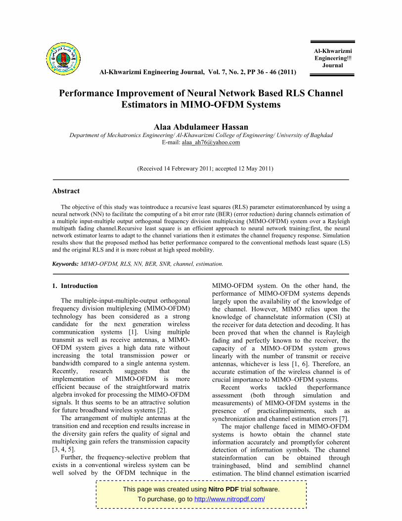
The DWT used here rather than the FFT since it is capable of reducing the power of intersymbolinterference (ISI) and intercarrier interference (ICI), which are caused by the loss in orthogonality between the carriers as a result of the multipath wireless channel (see [16It analyzes the signal at different frequency bands with different resolutions by decomposingthe signal into an approximation containing coarse(the high-scale, low-frequency componentsof the signal) and detailed information (the lowhigh-frequency components).
DWTemploys two sets of functions, known as scaling and wavelet functions, which are associatedwith low pass and high pass filters. The decomposition of the signal into different frequencybands is simply obtained by successihigh pass and low pass filtering of the time domainsignal [17, 18]. The original signal first passed through a half-band high pass filter anda half-band low pass filter (see figure (3))half-band low pass filter removes all frequencies that areabove half of the highest frequency, while a half-band high pass filter removes all frequenciesthat are below half of the highest frequency of the signal. The low pass filtering halves theresolution, but leaves the scale unchanged. The signal is then su(down-sampling, achieved by discarding alternate samples) by two since halfof the number of samples is redundant, according to the Nyquist’s rule.We produce two sequences called cfrequency) and cD (of high frequency).
Decomposition halves the time resolution since only half the number of samples then comes to characterize the entire signal. Conversely it doubles the frequency resolution, since the frequency band of the signal spans only half the previous frequencyband effectively reducing the uncertainty by half. This procedure, which is also known as subband coding, can be repeated for further decomposition (see figure (4)). At every level, the filtering and sub-sampling will result in
Al-Khwarizmi Engineering Journal, Vol. 7, No. 2, PP
OFDM transmitter has parallel transmission paths which are very
similar to the singleantenna OFDM system, each branch performing pilot insertion, IDWT before
converted to RF andtransmitted. It is worth noting that the channel encoder and thedigital modulation, in some spatial
stems, canalso be done per branch, where the modulated signals are thenspace-time coded using the Alamouti algorithm beforetransmitting from multiple antennas not necessarilyimplemented jointly over all the
used here rather than the FFT since it is capable of reducing the power of intersymbolinterference (ISI) and intercarrier interference (ICI), which are caused by the loss in orthogonality between the carriers as a result of
(see [16, 17, 18]). analyzes the signal at different frequency bands
with different resolutions by decomposingthe signal into an approximation containing coarse
frequency componentsof the detailed information (the low-scale,
DWTemploys two sets of functions, known as scaling and wavelet functions, which are associatedwith low pass and high pass filters. The decomposition of the signal into different frequencybands is simply obtained by successive
pass filtering of the time original signal xi[n] is band high pass filter
(see figure (3)). A band low pass filter removes all frequencies areabove half of the highest frequency, while
band high pass filter removes all frequenciesthat are below half of the highest frequency of the signal. The low pass filtering halves theresolution, but leaves the scale unchanged. The signal is then sub-sampled
, achieved by discarding alternate by two since halfof the number of
samples is redundant, according to the Nyquist’s We produce two sequences called cA (of low
Decomposition halves the time resolution since only half the number of samples then comes to characterize the entire signal. Conversely it doubles the frequency resolution, since the frequency band of the signal spans only half the
ffectively reducing the uncertainty by half. This procedure, which is also known as subband coding, can be repeated for further decomposition (see figure (4)). At every
sampling will result in
half the number of samples (and hetime resolution) and half the frequency bands being spanned (and hence doubles the frequency resolution).
Fig.3. Subband Coding; (Left): Frequency Representation, (Right): Tree-Structure
Fig.4. Decomposition of Input Signal
Assuming the channel impulse response remains constant during the entire OFDM block, the received signal vector that belongs to the receive antenna, is simply the linear convolution of transmitted symbols and the channelresponse vector; each of those Nis a combination of all the Nttransmitted signals and the distorting noise.Meanwhile compared to the SISO system, it complicates thesystem design regarding to channelestimation and symboldetection due to the hugely increased number of channelcoefficients.
Subsequently at thereceiver, the performed perreceiver branch. Next, thetransmitted symbol per TX antenna iscombined and outputted for the subsequent operations likedigital demodulation and decoding. Finally all the input binarydata are recovered with certain BER.
, PP 36 - 46 (2011)
half the number of samples (and hence half the time resolution) and half the frequency bands being spanned (and hence doubles the frequency
Subband Coding; (Left): Frequency Domain Structure [17].
Input Signal.
Assuming the channel impulse response remains constant during the entire OFDM block, the received signal vector that belongs to the jth
imply the linear convolution transmitted symbols and the channel impulse
Nrreceived signals transmitted signals
Meanwhile compared to the SISO system, it complicates thesystem design regarding to channelestimation and
due to the hugely increased
Subsequently at thereceiver, the DWT is performed perreceiver branch. Next,
antenna iscombined and outputted for the subsequent operations
decoding. Finally all the input binarydata are recovered with certain
This page was created using Nitro PDF trial software.
To purchase, go to http://www.nitropdf.com/

Alaa Abdulameer Hassan Al-Khwarizmi Engineering Journal, Vol. 7, No. 2, PP 36 - 46 (2011)
40
The output of DWT at the jth receive antenna can be expressed as;
( , ) = ( , ) ( , ) + ( , )…(5)
where ( , )represents the AWGN with zero
mean and = variance. ( , )denotes the
channel frequency response at time for the kth subcarrier between the ith transmit and jth receive antennas. The channel coefficients in frequency domain are obtained as linear combinations of the dispersive channel taps:
( , ) = ∑ ,( ) ⁄ …(6)
and the impulse response of the Rayleigh fading channel can be expressed as
ℎ ( , ) = ∑ ,( ) ( − ) …(7)
whereLt denotes the number of non-zero taps, , is the correspondingcomplex amplitude of
the lth non-zero tap, TOFDM is the OFDM symbol duration and is the delay associated to the lth tap. This delay and variance are assumed to be the same for each transmit-receive channel link. The power of the lth paths are normalized, such that ∑ = 1; [6, 10, 15, 19].
2.2. Space-Time Block Coded (STBC)OFDM
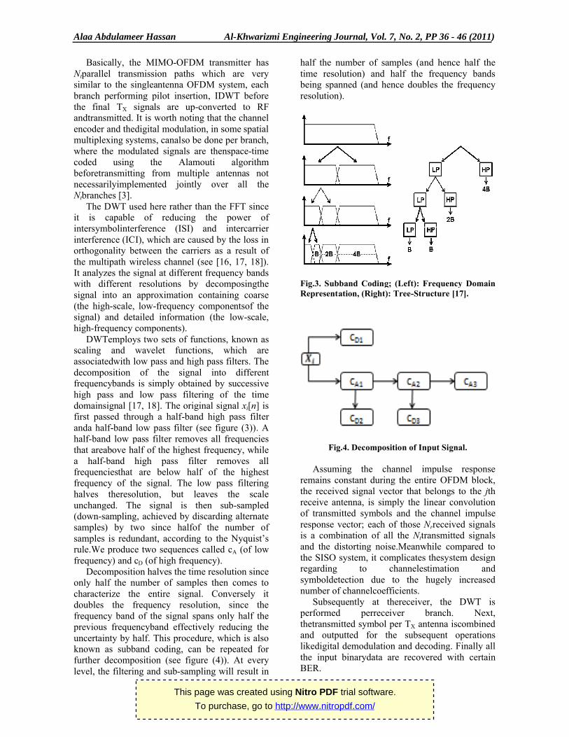
STBC introduces redundancy in space, through the addition of multiple antennas, and redundancy in time, through channel coding. Its main feature is to provide diversity gain, with very low decoding complexity. In this method (using two transmit antennas), the input data stream is first mapped into symbols using a constellation mapper, and the symbol stream is then divided into two substreams. The symbols and are transmitted from the first and second antenna respectively at time t and the symbols − ∗ and ∗are transmitted fromthe first and second antenna respectively at time + (the transmit sequences from the two transmit antennas are orthogonal). In this case the code matrix can be given as [3, 11, 13, 15]:
X = − ∗ ∗ …(8)
The block diagram of the Alamouti scheme is shown in figure (5) with one receiver antenna is used at the receiver. The fading channel
coefficients from the first and the second transmit antennas to the receive antenna at time t are denoted by h1(t) and h2(t), respectively. By assuming that the channel coefficients do not change in the interval from time t to + , they can be expressed as follows:
ℎ ( ) = |ℎ |
ℎ ( + ) = |ℎ | …(9)
whereℎ and , (i = 1,2) are the amplitude gain and phase shift for the path from antenna i to the receive antenna and Tsis the symbol duration.The received signals at the receiver antenna over two consecutive symbol periods for time t and + can be expressed as:
( ) = ℎ + ℎ +( + ) = − ∗ℎ + ∗ℎ + …(10)
So that,
= − ∗ ∗ ℎℎ + …(11)
Or rewrite (11) as in (3) where the channel matrix is give as:
H =ℎ ℎℎ∗ −ℎ∗ …(12)
Now, as in figure (5), and at time n, a data block ( , ), k = 0, 1, …, K-1 whereKis the number of subcarriers, is coded into two different symbol blocks, ( , ){the DWT of },i = 1,2.Then the received signal is the superposition of the transmitted signals and can be expressed as:
( , ) = ( , ) ( , ) + ( , ) ( , ) + ( , ) …(13)
Again, ( , ) denotes the channel frequency response of the multipath channel and the kthsubchannel between the ith transmit and receive antennas.
And previously, we assumed that the channel coefficients do not change in the interval from time to time + 1(the channel gains between two adjacent subchannels are approximately equal); then ( , ) = ( + 1, ) = ( ), and the demodulated signal ( , ) is then decoded by the linear maximum-likelihood (ML) space-time decoder [3, 11, 13, 15]:
( , ) = ∗( ) ( , ) + ( ) ∗( + 1, )( + 1, ) = ∗( ) ( , )
− ( ) ∗( + 1, ) …(14)
This page was created using Nitro PDF trial software.
To purchase, go to http://www.nitropdf.com/
Alaa Abdulameer Hassan Al
Finally the estimated symbolsare obtained also[6, 20])so that to minimize the Euclidean distance to the received signal.
Fig
3. Proposed Channel Estimation Method
3.1. MLP Predictor
The most common neural network model is the feed-forward Multi-Layered Perceptrons (MLP). This type of neural network is known as a supervised network because it requires a desired output in order to learn. These networks are widely used for their capability in minimizing cost functions.And among other advantages, they can be entirely made ofsimple electronic devices, such as capacitors, resistors, and operational amplifiers, also suitable for the implementation in very large scale integration(VLSI) technology. This implementation can keep the complexity of the receiver low [21], because it is not directly related to the number of additions and multiplications needed for the problem resolution.Thus, to minimize error functions, these networkare trained, here, with the use of the RLS algorithm.
Our networkuses two hidden layers where eachelement i j of a weight ( ij) matrix represents the connection weight connecting neuron downstream layer (i/p, hidden and o/p layers) to neuron j of the upstream layer.Now,
Ŝ ( , ) = ( )| ( , )| +
Al-Khwarizmi Engineering Journal, Vol. 7, No. 2, PP
Finally the estimated symbolsare obtained (see the Euclidean
Ŝ ( , ) = | ( , ) −Ŝ ( + 1, ) = | ( + ( ) ∗( + 1,
Fig.5. STBC-OFDM System Model.
Proposed Channel Estimation Method
The most common neural network model is the Layered Perceptrons (MLP).
This type of neural network is known as a supervised network because it requires a desired
These networks are ty in minimizing cost
functions.And among other advantages, they can be entirely made ofsimple electronic devices, such as capacitors, resistors, and operational amplifiers, also suitable for the implementation in very large
ogy. This implementation can keep the complexity of the
, because it is not directly related to the number of additions and multiplications
Thus, to minimize error functions, these networksare trained, here, with the use of the RLS
Our networkuses two hidden layers where each) matrix represents the
connection weight connecting neuron i of the downstream layer (i/p, hidden and o/p layers) to
) + ( )…(16)
where (. ) is a sigmoid function of each neuron,
expressed as, ( ) = , and
vector.The required goal, is the learning of
associations equations (15) & must restore the desired output in (15) close to the actual one in (16). Therefore an error signal will present, ( ). If an error has occurred, then only the weights on the connections from units that sent a non-zero signal to the outadjusted; i.e.
( ) = ( ) + | (where is the target value (=learning rate (0 < < 1) [22].
The same thing is forŜ ( +3.2. RLS Learning Algorithm
From the viewpoint of adaptive filteringtheory, it is well known that the recursive least squares (RLS) algorithm is typically an order of magnitude faster than the LMS algorithm [Thus, to speed up the convergence of algorithm, the weightsin each layer can be adjusted using the RLS algorithm.
The RLS attempts to minimize the cost function created from the exponentially weighted and windowed sum of the squared error. The channel estimate of ( )derived and updated as follows.
( , ) = ∑ |
, PP 36 - 46 (2011)
) ∗( ) ( , )|( + 1, ) −, )| …(15)
is a sigmoid function of each neuron,
, and ( ) is a bias
The required goal, is the learning of quations (15) & (16): the network
must restore the desired output in (15) close to the Therefore an error signal will
If an error has occurred, then only the weights on the connections from units that
zero signal to the output unit will be
( , )| …(17)
=1) and is the
( 1, ).
RLS Learning Algorithm
From the viewpoint of adaptive filteringtheory, it is well known that the recursive least squares (RLS) algorithm is typically an order of magnitude faster than the LMS algorithm [23]. Thus, to speed up the convergence of MLP
, the weightsin each layer can be orithm.
The RLS attempts to minimize the cost function created from the exponentially weighted and windowed sum of the squared error. ( ) in (15) will be derived and updated as follows.
( , )| …(18)
This page was created using Nitro PDF trial software.
To purchase, go to http://www.nitropdf.com/

Alaa Abdulameer Hassan Al-Khwarizmi Engineering Journal, Vol. 7, No. 2, PP 36 - 46 (2011)
42
where the error signal ( , ) may be expressed as:
( , ) = ( , ) − ∗( ) ( , ) …(19)
while denotes the forgetting factor (0 < < 1)that enables the receiver to track the change in a nonstationary environment by forgetting past observed data.
The channel estimate ( ) is the one that
minimizes ( , ).Solving ( , )
( )= 0 gives [14,
24]:
( ) = ( ) ( ) …(20)
where ( )is an autocorrelation function which may be calculated recursively as follows:
( ) = ∑ | ( , )| = ( ) + | ( , )| …(21)
while ( )is a crosscorrelation matrix and may be expressed as:
( ) = ∑ | ( , )|| ( , )| = ( ) + | ( , )|| ( , )|
…(22)
The same procedure is applied for ( +1, )and ( + 1, ).
4. Results and Discussion
The performance limit of MIMO-OFDMsystem for different antenna configuration is quantified through BER which is particularly anattractive measurement for wireless communications. A system equipped with two transmit antennas and arbitrary number of receive antennas is considered for this purpose. In the simulation scenarios the QPSK modulation is used and Rayleigh fading radio channel is assumed.
In the first simulation, the STBC is applied for two transmit antennas and different number of receive antennas to demonstrate the performance of the considered system atperfectchannelknowledge.
Figure (6) shows the BER performance comparison between 2×2, 2×4 and 2×6 STBC systems. As can be observed from the figure, the 2×6 system performs better than others. For example, the BER of 8*10-5 is achieved at SNR = 2 dB for 2×6 system, whereas the same BER is achieved at SNR = 5dB for 2×4 and at SNR = 7dB for 2×2 system. It rejects that the BER performance increases as the number of receive antennas increases for the same number of transmit antennas (see [11] to compare these results).
Fig.6. BER Performance Comparison between 2×2, 2×4 and 2×6 STBC Systems.
0 2 4 6 8 10 12 1410
-7
10-6
10-5
10-4
10-3
10-2
10-1
100
SNR (dB)
BER
2x2 STBC 2x4 STBC 2x6 STBC
This page was created using Nitro PDF trial software.
To purchase, go to http://www.nitropdf.com/

Alaa Abdulameer Hassan Al-Khwarizmi Engineering Journal, Vol. 7, No. 2, PP 36 - 46 (2011)
43
0 2 4 6 8 10 12 1410
-7
10-6
10-5
10-4
10-3
10-2
10-1
100
SNR (dB)
BER
LS RLS
MLP RLS Perfect CSI
Fig.7. Performance Comparison between Different Channel Estimations.
Fig.8. Performance of the Proposed Method in Different Modulation Types.
Figure (7) illustrates a performance comparison between differenttraining based channel estimations for 2×4 MIMO system.
Anideal channel estimation is also calculated for comparison.From the figure,it can be observed that the BER performance of RLS estimation
0 2 4 6 8 10 12 1410
-7
10-6
10-5
10-4
10-3
10-2
10-1
100
SNR (dB)
BER
64QAM QAM QPSK BPSK
This page was created using Nitro PDF trial software.
To purchase, go to http://www.nitropdf.com/

Alaa Abdulameer Hassan Al-Khwarizmi Engineering Journal, Vol. 7, No. 2, PP 36 - 46 (2011)
44
(with/without intelligent algorithm) isslightly worse than perfect CSI, but much better than LS estimation.
Figure (8) demonstrates the performance of the proposed channelestimation method for different modulation techniques (also under 2×4STBC system). As seen in this figure for a certain level of BER (say 1*10-4), different values obtained of SNR against the corresponding modulation type; 1.78 dB (BPSK), 2.31 dB (QPSK), 5.95 dB (QAM) and 7.16 dB (64QAM).
5. Conclusion
The results of our study can be summarized briefly as follows:1. An RLSbased MLP algorithm for complex
valued neuralnetwork is fully derived.2. The derived algorithm has been tested over
multipath communication channels and implemented using a DWT. The need to this transform is to mitigate theserious interferences, ISI and ICI appeared while usingthe FFT; also there is no need to insert a cyclic prefix between OFDM symbols and then this will eliminate the bandwidth.
Moreover, the proposed model performance isalso found to be consistent under different signal constellations, and compared with the conventional LS algorithm as described in figures (7&8).
3. The use of the RLSbased MLP for complex valued neuralnetwork has resulted in substantial improvements in termof BER.It is proved that this rate is reduced in all cases as explained previously in the comments on figures (6&7).
6. References
[1] Feng Wan et al, A Semiblind Channel Estimation Approach for MIMO-OFDM Systems, IEEE Transactions on Signal Processing, Vol. 56, No. 7, July 2008.
[2] M. Mitra, Investigating the Impact of Spectrum Efficient of OFDM-MIMO and MC-CDMA-MIMO Communication System for ITS, Journal of Theoretical and Applied Information Technology (JATIT), 2010.
[3] Kala Praveen Bagadi, MIMO-OFDM Channel Estimation Using Pilot Carries, International Journal of Computer
Applications (0975 – 8887), VOL. 2, No.3, May 2010.
[4] Eth Zurich, MIMO-OFDM Wireless Systems: Basics, Perspectives, and Challenges, IEEE Wireless Communications, August 2006.
[5] Jari Ylioina, Iterative Detection, Decoding, and Channel Estimation in MIMO-OFDM, Academic dissertation to be presented with the assent of the Faculty of Technology of the University of Oulu for public defense in Auditorium IT116, Linnanmaa, on 10 June 2010.
[6] V. Le Nir et al, Combination of Space-Time Block Coding with MC-CDMA Technique for MIMO systems with two, three and four transmit antennas, European Union IST research project MATRICE (Multicarrier CDMA Transmission Techniques for Integrated Broadband Cellular Systems),2002.
[7] Marcello Cicerone, Channel Estimation for MIMO-OFDM Systems by Modal Analysis/Filtering, IEEE Transactions on Communication, Vol. 54, No. 11, November 2006.
[8] Yong Xu et al, Generalized RLS Approach to the Training of Neural Networks, IEEE Transactions on Neural Networks, Vol. 17, No. 1, January 2006.
[9] F. Sarabchi, and M. E. Kalantari, Space Time Processing with Adaptive STBC-OFDM Systems, World Academy of Science, Engineering and Technology 2009.
[10] Yuri Labrador et al, OFDM MIMO Space Diversity in Terrestrial Channels, IJCSNS International Journal of Computer Science and Network Security, Vol.9, No.10, October 2009.
[11] M. T. Islam et al, Performance and Complexity Improvement of Training Based Channel Estimation in MIMO Systems, Progress In Electromagnetics Research C, Vol. 10, 1-13, 2009.
[12] Ye (Geoffrey) Li et al, MIMO-OFDM for Wireless Communications: Signal Detection with Enhanced Channel Estimation, IEEE Transactions on Communication, Vol. 50, No. 9, September 2002.
[13] Yonghong Zeng et al, Semiblind Channel Estimation and Equalization for MIMO Space-Time Coded OFDM, IEEE Transactions on Circuits and Systems-I: Regular Papers, Vol. 53, No. 2, February 2006.
This page was created using Nitro PDF trial software.
To purchase, go to http://www.nitropdf.com/

Alaa Abdulameer Hassan Al-Khwarizmi Engineering Journal, Vol. 7, No. 2, PP 36 - 46 (2011)
45
[14] Jos Akhtman and LajosHanzo, Advanced Channel Estimation for MIMO-OFDM in Realistic Channel Conditions, IEEE Transactions on Communication,1-4244-0353 7/07/$25 ©IEEE 2007.
[15] İlhan BAŞTÜ RK, Iterative Channel Estimation Techniques for Multiple Input Multiple Output Orthogonal Frequency Division Multiplexing Systems, Thesis (Master of Science), Graduate School of Engineering and Sciences of İzmir Institute of Technology, July 2007.
[16] B.G. Negash and H.Nikookar, Wavelet Based OFDM for Wireless Channels, International Research Center for Telecommunications-Transmission and Radar Faculty of Information Technology and Systems, Delft University of Technology, 0-780~-6728-6/010.000/2001 IEEE.
[17] M. K. Lakshmananand H. Nikookar, A Review of Wavelets for Digital Wireless Communication, Wireless Personal Communications (2006) 37: 387–420, DOI: 10.1007/s11277-006-9077-y, Springer 2006.
[18] Khaizuran Abdullah and Zahir M. Hussain, Studies on DWT-OFDM and FFT-OFDM Systems, International Conference on Communication, Computer and Power (ICCCP), Muscat, February 15-18, 2009.
[19] HelkaMäättänen, MIMO-OFDM, S-72.333Postgraduate Course in Radio Communications.
[20] Somkiat Lerkvaranyu and Yoshikazu Miyanaga, ML Detection with Symbol Estimation for Nonlinear Distortion of OFDM Signal, World Academy of Science, Engineering and Technology 2, 2005.
[21] Romano Fantacci et al, A Neural Network Approach to MMSE Receivers in a DS-CDMA Multipath Fading Environment,IEEE Transactions on Communications, Vol. 54, No. 5, May 2006.
[22] S. N. Sivanandam and M. Paulraj, Introduction to Artificial Neural Networks, Book, Vikas Publishing Hous PVT LTD, 2004.
[23] Azzedine Zerguine et al, Recursive Least-Squares Backpropagation Algorithm for Stop-and-Go Decision-Directed Blind Equalization, IEEE Transactions on Neural Networks, Vol. 13, No. 6, November, 2002.
[24] Yohei Kojima et al, RLS Channel Estimation with Adaptive Forgetting Factor for DS-CDMA Frequency-Domain Equalization, IEICE Transactions on Communications, Vol. E92-B, No. 5, May 2009.
This page was created using Nitro PDF trial software.
To purchase, go to http://www.nitropdf.com/

46 ، صفحة2، العدد 7مجلة الخوارزمي الھندسیة المجلد عالء عبداألمیر حسن - 36 )2011(
46
تحسین أداء تقدیرات القناة باستعمال الشبكة العصبیة لتدریب خوارزمیة
تكرار أقل األجزاء لتقدیر العنصر في أنظمة مزج تقسیمات التردد المتعامد المتعدد االدخاالت المتعدد االخراجات
عالء عبداألمیر حسن جامعة بغداد/ الھندسة الخوارزميكیة /المیكاترونكس ھندسة قسم
[email protected]: البرید االلكتروني
الخالصة
ة ان لتقدیمخوارزمی ة ك ذه الدراس وع ھ ر (أن موض دیر العنص زاء لتق ل األج رار أق ھیل أداء ) تك ـبیةكطریقة لتس بكات العصی تخدام الش دة بأس والمعض
أ دل الخط اب مع أ (وأحتس دل الخط اقص مع دد ) تن االت المتع دد األدخ دة المتع ردد المتعام یمات الت زج تقس ام م وات نظ دیر لقن ة التق ق خوارزمی اء تطبی أثن
بیة " أن خوارزمیة تكرار أقل األجزاء یمكن أعتبارھا فعالة جدا). رایلییف(األخراجات عبر قناة البھت متعدد المسار بكة العص دریب الش ث "أوال: لت ن حی ، م
ردد اة للت تجابة القن دیر أس م تق تمرار، ث اة بأس دة أداءا . تدریب الشبكة العصبیة لتقدیر تغییرات القن ة المعتم ل للطریق ائج التمثی رت نت دا " أظھ ت " جی ا قورن أذا م
ة رى كخوارزمی رق األخ زاء (الطریقة بغیرھا من الط ل األج ة (أو ) أق ر الذكی ة وغی زاء التقلیدی ل األج رار أق رت ). تك ي أظھ اءة ف ذلك كف دة ك ة المعتم الطریق
.فعالیات النظام السریعة
This page was created using Nitro PDF trial software.
To purchase, go to http://www.nitropdf.com/