pinnacle manual pi8127 -...
TRANSCRIPT

Pinnacle®
Gas Boilers Rev 2
Peerless®
Stainless Steel
Installation,Operation &MaintenanceManual
– Do not store or use gasoline or otherflammable vapors and liquids in the vicinityof this or any other appliance.
– WHAT TO DO IF YOU SMELL GAS• Do not try to light any appliance.
• Do not touch any electrical switch;do not use any phone in your building.
• Immediately call your gas supplier froma neighbor’s phone. Follow the gassupplier’s instructions.
• If you cannot reach your gas supplier,call the fire department.
– Installation and service must be performedby a qualified installer, service agency orthe gas supplier.
If the information in this manual is notfollowed exactly, a fire or explosion mayresult causing property damage, personalinjury or loss of life.
WARNING
As an ENERGY STAR®
Partner, PB Heat, LLC hasdetermined that this product meets the ENERGY STAR
®
guidelines for energy efficiency.
USING THIS MANUAL 1A. INSTALLATION SEQUENCE . . . . . . . . . . . . .1B. SPECIAL ATTENTION BOXES . . . . . . . . . . . .1
1. PREINSTALLATION 2
A. GENERAL . . . . . . . . . . . . . . . . . . . . . . . . . . . .2B. CODES & REGULATIONS . . . . . . . . . . . . . . .2C. ACCESSIBILITY CLEARANCES . . . . . . . . . . .3
D. COMBUSTION AND VENTILATION AIR . . . .3
E. PLANNING THE LAYOUT . . . . . . . . . . . . . . . .3
2. BOILER SET-UP 4
A. GENERAL . . . . . . . . . . . . . . . . . . . . . . . . . . . .4B. WALL HUNG BOILERS . . . . . . . . . . . . . . . . . .4C. FLOOR MOUNTED BOILERS . . . . . . . . . . . . .4
3. WATER PIPING AND CONTROLS 5A. GENERAL . . . . . . . . . . . . . . . . . . . . . . . . . . . .5B. OPERATING PARAMETERS . . . . . . . . . . . . . .5C. SYSTEM COMPONENTS . . . . . . . . . . . . . . . .5D. SYSTEM PIPING . . . . . . . . . . . . . . . . . . . . . . .7E. FREEZE PROTECTION . . . . . . . . . . . . . . . . . .8F. SPECIAL APPLICATIONS . . . . . . . . . . . . . . . .8
4. GAS PIPING 15A. GENERAL . . . . . . . . . . . . . . . . . . . . . . . . . . .15B. FUEL LINE SIZING . . . . . . . . . . . . . . . . . . . .15C. GAS SUPPLY PIPING INSTALLATION . . . . .15D. GAS SUPPLY PIPING – OPERATION . . . . . .16E. MAIN GAS VALVE – OPERATION . . . . . . . .17
5. VENTING, INTAKE AIR & CONDENSATE 18A. GENERAL . . . . . . . . . . . . . . . . . . . . . . . . . . .18B. APPROVED MATERIALS FOR EXHAUST
VENT AND INTAKE AIR PIPE . . . . . . . . . . .18C. EXHAUST VENT / AIR INTAKE PIPE
LOCATION . . . . . . . . . . . . . . . . . . . . . . . . . .18D. EXHAUST VENT AND INTAKE AIR PIPE
SIZING . . . . . . . . . . . . . . . . . . . . . . . . . . . . .19
E. EXHAUST VENT AND AIR INLET PIPEINSTALLATION . . . . . . . . . . . . . . . . . . . . . . .20
F. EXHAUST TAPPING FOR VENTSAMPLE . . . . . . . . . . . . . . . . . . . . . . . . . . . .24
G. CONDENSATE DRAIN INSTALLATION . . . .24H. BOILER REMOVAL FROM COMMON
VENTING SYSTEM . . . . . . . . . . . . . . . . . . .24
6. ELECTRICAL 25A. WIRING . . . . . . . . . . . . . . . . . . . . . . . . . . . . .25B. SEQUENCE OF OPERATION . . . . . . . . . . . .26C. SAFETY INTERLOCKS . . . . . . . . . . . . . . . . .28D. CONTROL FUNCTIONS . . . . . . . . . . . . . . . .29E. HEATING CURVE . . . . . . . . . . . . . . . . . . . . .31
7. START-UP PROCEDURES 33A. COMPLETING THE INSTALLATION . . . . . . .33B. LIGHTING/OPERATING PROCEDURES . . . .34C. CHECK-OUT PROCEDURE . . . . . . . . . . . . . .35
8. TROUBLESHOOTING 37A. BOILER ERROR CODES . . . . . . . . . . . . . . . .37B. BOILER FAULT CODES . . . . . . . . . . . . . . . .37
9. MAINTENANCE 39A. GENERAL (WITH BOILER IN USE) . . . . . . .40B. WEEKLY (WITH BOILER IN USE) . . . . . . . . .40C. ANNUALLY (BEFORE START OF
HEATING SEASON) . . . . . . . . . . . . . . . . . . .40D. CONDENSATE CLEANING
INSTRUCTIONS . . . . . . . . . . . . . . . . . . . . . .40E. COMBUSTION CHAMBER COIL
CLEANING INSTRUCTIONS . . . . . . . . . . . .41
10. BOILER DIMENSIONS & RATINGS 42A. BOILER DIMENSIONS . . . . . . . . . . . . . . . . .42
11. REPAIR PARTS 46
APPENDIX A. STARTUP COMBUSTIONRECORD 50
TABLE OF CONTENTS
TABLE OF CONTENTS

1
A. INSTALLATION SEQUENCEFollow the installation instructions provided in thismanual in the order shown. The order of theseinstructions has been set in order to provide the installerwith a logical sequence of steps that will minimizepotential interferences and maximize safety duringboiler installation.
B. SPECIAL ATTENTION BOXESThroughout this manual you will see special attentionboxes intended to supplement the instructions and makespecial notice of potential hazards. These categoriesmean, in the judgment of PB Heat, LLC:
Indicates special attention is needed, but not directlyrelated to potential personal injury or propertydamage.
NOTICE
Indicates a condition or hazard which will or cancause minor personal injury or property damage.
CAUTION
DANGERIndicates a condition or hazard which will causesevere personal injury, death or major propertydamage.
USING THIS MANUAL
USING THIS MANUAL
Indicates a condition or hazard which may causesevere personal injury, death or major propertydamage.
WARNING
2
A. GENERAL
1. Pinnacle boilers are supplied completely assembledas packaged boilers. The package should beinspected for damage upon receipt and any damageto the unit should be reported to the shippingcompany and wholesaler. This boiler should bestored in a clean, dry area.
2. Carefully read these instructions and be sure tounderstand the function of all connections prior tobeginning installation. Contact your PB Heat, LLCRepresentative for help in answering questions.
3. This boiler must be installed by a qualifiedcontractor. The boiler warranty may be voided if theboiler is not installed correctly.
4. A hot water boiler installed above radiation or asrequired by the Authority having jurisdiction, must beprovided with a low water fuel cut-off device either aspart of the boiler or at the time of installation.
5. This boiler can be installed at high altitudes above5,000 feet with no burner adjustments. This appliesto boilers equipped for firing natural gas or liquefiedpetroleum (LP) gas.
B. CODES & REGULATIONS
1. Installation and repairs are to be performed in strictaccordance with the requirements of state and localregulating agencies and codes dealing with boilerand gas appliance installation.
2. In the absence of local requirements the followingshould be followed.a. ASME Boiler and Pressure Vessel Code, Section
IV - "Heating Boilers"
b. ASME Boiler and Pressure Vessel Code, SectionVI - Recommended Rules for the Care andOperation of Heating Boilers"
c. ANSI Z223.1/NFPA 54 - "National Fuel Gas Code"
d. ANSI/NFPA 70 - "National Electrical Code"
e. ANSI/NFPA 211 - "Chimneys, Fireplaces, Ventsand Solid Fuel Burning Appliances"
3. Where required by the authority havingjurisdiction, the installation must conform to theStandard for Controls and Safety Devices forAutomatically Fired Boilers, ANSI/ASME CSD-1.
**Please read if installing in Massachusetts**Massachusetts requires manufacturers of Side WallVented boilers to provide the following informationfrom the Massachusetts code:
· A hard wired carbon monoxide detector with analarm and battery back-up must be installed onthe floor level where the gas equipment is to beinstalled AND on each additional level of thedwelling, building or structure served by the sidewall horizontal vented gas fueled equipment.
· In the event that the side wall horizontally ventedgas fueled equipment is installed in a crawl spaceor an attic, the hard wired carbon monoxidedetector with alarm and battery back-up may beinstalled on the next adjacent floor level.
· Detector(s) must be installed by qualifiedlicensed professionals.
· APPROVED CARBON MONOXIDEDETECTORS: Each carbon monoxide detectorshall comply with NFPA 720 and be ANSI/UL2034 listed and IAS certified.
· SIGNAGE: A metal or plastic identification plateshall be permanently mounted to the exterior ofthe building at a minimum height of eight (8)feet above grade directly in line with the exhaustvent terminal for the horizontally vented gasfueled heating appliance or equipment. The signshall read, in print size no less than one-half (1/2)inch in size, “GAS VENT DIRECTLY BELOW.KEEP CLEAR OF ALL OBSTRUCTIONS”.
· EXEMPTIONS to the requirements listed above:
° The above requirements do not apply if theexhaust vent termination is seven (7) feet ormore above finished grade in the area of theventing, including but not limited to decksand porches.
° The above requirements do not apply to aboiler installed in a room or structure separatefrom the dwelling, building or structure usedin whole or in part for residential purposes.
· The boiler installation manual, ventmanufacturer's installation manual, and thissupplement shall remain with the boiler at thecompletion of the installation.
See latest edition of Massachusetts Code 248 CMR forcomplete verbage and also for additional (non-ventrelated) requirements (248 CMR is available online).
If your installation is NOT in Massachusetts, pleasesee your authority of jurisdiction for requirementsthat may be in effect in your area. In the absence ofsuch requirements, follow the National Fuel GasCode, ANSI Z223.1/NFPA 54 and/or CAN/CSAB149.1, Natural Gas and Propane Installation Code.
PREINSTALLATION
1. PREINSTALLATION
Liquefied Petroleum (LP) Gas or Propane is heavierthan air and, in the event of a leak, may collect in lowareas such as basements or floor drains. The gasmay then ignite resulting in a fire or explosion.
WARNING
C. ACCESSIBILITY CLEARANCES
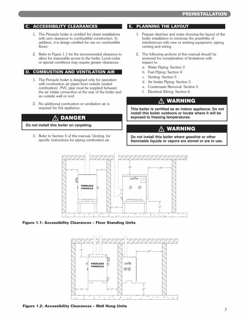
1. The Pinnacle boiler is certified for closet installationswith zero clearance to combustible construction. Inaddition, it is design certified for use on combustiblefloors.
2. Refer to Figure 1.1 for the recommended clearance toallow for reasonable access to the boiler. Local codesor special conditions may require greater clearances.
D. COMBUSTION AND VENTILATION AIR
1. The Pinnacle boiler is designed only for operationwith combustion air piped from outside (sealedcombustion). PVC pipe must be supplied betweenthe air intake connection at the rear of the boiler andan outside wall or roof.
2. No additional combustion or ventilation air isrequired for this appliance.
3. Refer to Section 5 of this manual, Venting, forspecific instructions for piping combustion air.
E. PLANNING THE LAYOUT
1. Prepare sketches and notes showing the layout of theboiler installation to minimize the possibility ofinterferences with new or existing equipment, piping,venting and wiring.
2. The following sections of this manual should bereviewed for consideration of limitations with respect to:a. Water Piping: Section 3b. Fuel Piping: Section 4c. Venting: Section 5d. Air Intake Piping: Section 5e. Condensate Removal: Section 5f. Electrical Wiring: Section 6
PREINSTALLATION
Do not install this boiler where gasoline or otherflammable liquids or vapors are stored or are in use.
WARNING
This boiler is certified as an indoor appliance. Do notinstall this boiler outdoors or locate where it will beexposed to freezing temperatures.
WARNING
3
Do not install this boiler on carpeting.
DANGER
Figure 1.2: Accessibility Clearances – Wall Hung Units
Figure 1.1: Accessibility Clearances – Floor Standing Units
4
A. GENERAL
1. Pinnacle boilers are to be installed in an area with afloor drain or in a suitable drain pan. Do not installany boiler where leaks or relief valve discharge willcause property damage.
2. This boiler is not intended to support external piping.All venting and other piping should be supportedindependently of the boiler.
3. Install this boiler level to prevent condensate frombacking up inside the boiler.
B. WALL HUNG BOILERS
1. The PI-T50 and PI-T80 Boilers are provided withslots for wall mounting and feet for floor mounting.Refer to Figure 10.1 in this manual for dimensions &locations.
2. If wall mounted, the boiler must be attached to awall that provides adequate support for the boiler.
3. Use a minimum of 1/4" threaded fasteners forsupporting the boiler. Do not mount the boiler towall board only.
4. Be sure to adequately support the boiler whileinstalling external piping. Be sure to pipe condensateto a suitable drain or condensate pump.
C. FLOOR MOUNTED BOILERS
1. PI-80, PI-140, and PI-199 boilers are designed forfloor mounting. The PI-80 can be wall mountedusing the optional boiler stand available throughyour PB Heat, LLC distributor (Part Number 91439).
2. The boiler stand may used for floor mounting of thePI-140 and PI-199 boilers.
2. BOILER SET-UP
BOILER SET-UP
This boiler is must be installed level to preventcondensate from backing up inside the boiler.
CAUTION
Make sure the boiler is adequately supported. Do notinstall this boiler on drywall unless adequatelysupported by wall studs.
WARNING
A. GENERAL
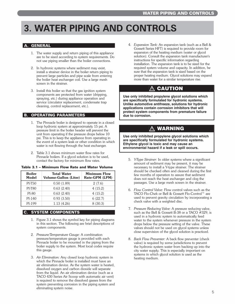
1. The water supply and return piping of this applianceare to be sized according to system requirements. Donot use piping smaller than the boiler connections.
2. In hydronic systems where sediment may exist,install a strainer device in the boiler return piping toprevent large particles and pipe scale from enteringthe boiler heat exchanger coil. Use a large meshscreen in the strainer.
3. Install this boiler so that the gas ignition systemcomponents are protected from water (dripping,spraying, etc.) during appliance operation andservice (circulator replacement, condensate trapcleaning, control replacement, etc.).
B. OPERATING PARAMETERS
1. The Pinnacle boiler is designed to operate in a closedloop hydronic system at approximately 15 psi. Apressure limit in the boiler header will prevent theunit from operating if the pressure drops below 10psi. This is to keep the appliance from operating inthe event of a system leak or other condition in whichwater is not flowing through the heat exchanger.
2. Table 3.1 shows minimum water flow rates forPinnacle boilers. If a glycol solution is to be used,contact the factory for minimum flow rates.
C. SYSTEM COMPONENTS
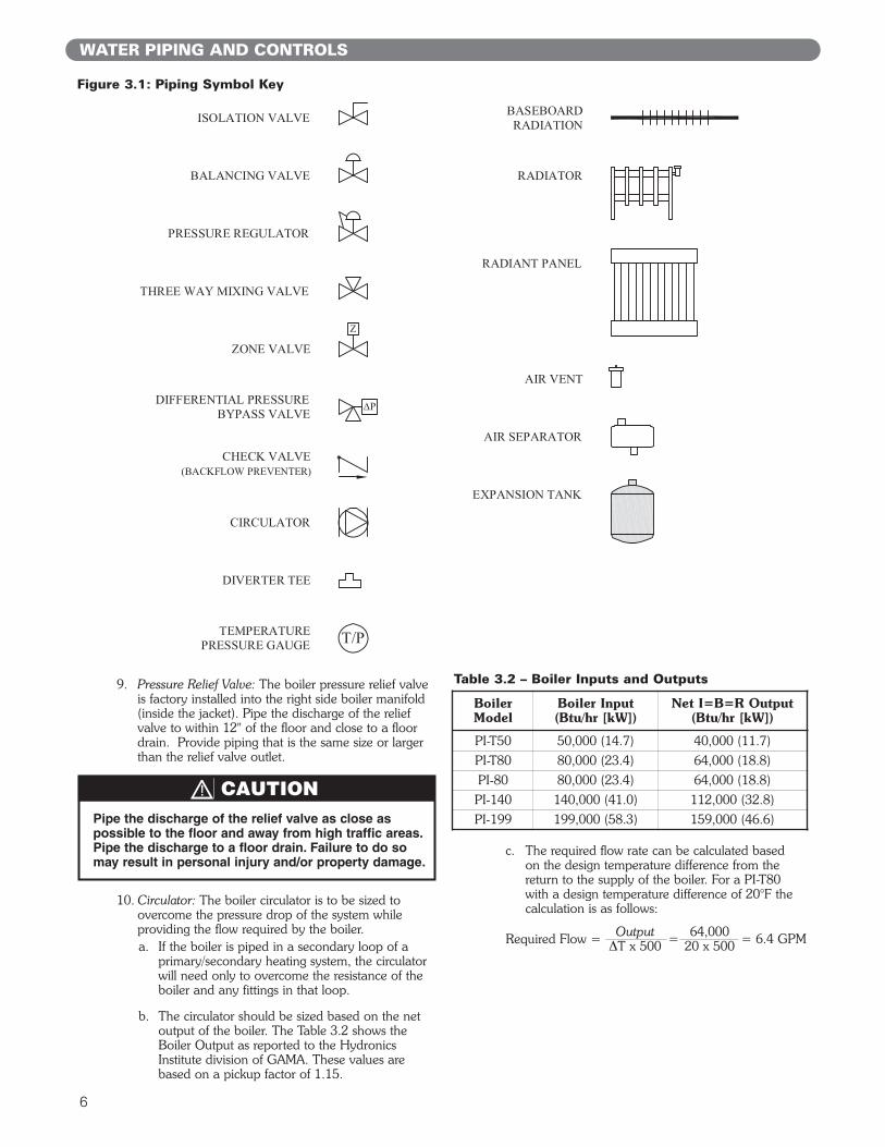
1. Figure 3.1 shows the symbol key for piping diagramsin this section. The following are brief descriptions ofsystem components.
2. Pressure/Temperature Gauge: A combinationpressure/temperature gauge is provided with eachPinnacle boiler to be mounted in the piping from theboiler supply to the system. Most local codes requirethis gauge.
3. Air Elimination: Any closed loop hydronic system inwhich the Pinnacle boiler is installed must have anair elimination device. As the system water is heated,dissolved oxygen and carbon dioxide will separatefrom the liquid. An air elimination device (such as aTACO 430 Series Air Scoop with automatic air vent)is required to remove the dissolved gasses from thesystem preventing corrosion in the piping system andeliminating system noise.
4. Expansion Tank: An expansion tank (such as a Bell &Gossett Series HFT) is required to provide room forexpansion of the heating medium (water or glycolsolution). Consult the expansion tank manufacturer'sinstructions for specific information regardinginstallation. The expansion tank is to be sized for therequired system volume and capacity. In addition, besure that the expansion tank is sized based on theproper heating medium. Glycol solutions may expandmore than water for a similar temperature rise.
5. Y-Type Strainer: In older systems where a significantamount of sediment may be present, it may benecessary to install a Y-type strainer. The strainershould be checked often and cleaned during the firstfew months of operation to assure that sedimentdoes not reach the heat exchanger and clog thepassages. Use a large mesh screen in the strainer.
6. Flow Control Valve: Flow control valves such as theTACO Flo-Chek or Bell & Gossett Flo-Control™ areused to prevent gravity circulation by incorporating acheck valve with a weighted disc.
7. Pressure Reducing Valve: A pressure reducing valve,such as the Bell & Gossett B-38 or a TACO #329, isused in a hydronic system to automatically feedwater to the system whenever pressure in the systemdrops below the pressure setting of the valve. Thesevalves should not be used on glycol systems unlessclose supervision of the glycol solution is practiced.
8. Back Flow Preventer: A back flow preventer (checkvalve) is required by some jurisdictions to preventthe hydronic system water from backing up into thecity water supply. This is especially important onsystems in which glycol solution is used as theheating medium.
3. WATER PIPING AND CONTROLS
WATER PIPING AND CONTROLS
Table 3.1 – Minimum Flow Rate and Water Volume
Boiler Model
Total Water Volume-Gallon (Liter)
Minimum FlowRate-GPM (LPM)
PI-T50 0.50 (1.89) 2 (7.6)PI-T80 0.63 (2.40) 4 (15.2)PI-80 0.63 (2.40) 4 (15.2)
PI-140 0.93 (3.50) 6 (22.7)PI-199 1.13 (4.26) 8 (30.3)
Use only inhibited propylene glycol solutions whichare specifically formulated for hydronic systems.Unlike automotive antifreeze, solutions for hydronicapplications contain corrosion inhibitors that willprotect system components from premature failuredue to corrosion.
CAUTION
Use only inhibited propylene glycol solutions whichare specifically formulated for hydronic systems.Ethylene glycol is toxic and may cause anenvironmental hazard if a leak or spill occurs.
WARNING
5
6
9. Pressure Relief Valve: The boiler pressure relief valveis factory installed into the right side boiler manifold(inside the jacket). Pipe the discharge of the reliefvalve to within 12" of the floor and close to a floordrain. Provide piping that is the same size or largerthan the relief valve outlet.
10. Circulator: The boiler circulator is to be sized toovercome the pressure drop of the system whileproviding the flow required by the boiler. a. If the boiler is piped in a secondary loop of a
primary/secondary heating system, the circulatorwill need only to overcome the resistance of theboiler and any fittings in that loop.
b. The circulator should be sized based on the netoutput of the boiler. The Table 3.2 shows theBoiler Output as reported to the HydronicsInstitute division of GAMA. These values arebased on a pickup factor of 1.15.
c. The required flow rate can be calculated basedon the design temperature difference from thereturn to the supply of the boiler. For a PI-T80with a design temperature difference of 20°F thecalculation is as follows:
WATER PIPING AND CONTROLS
Table 3.2 – Boiler Inputs and Outputs
Boiler Model
Boiler Input(Btu/hr [kW])
Net I=B=R Output(Btu/hr [kW])
PI-T50 50,000 (14.7) 40,000 (11.7)PI-T80 80,000 (23.4) 64,000 (18.8)PI-80 80,000 (23.4) 64,000 (18.8)
PI-140 140,000 (41.0) 112,000 (32.8)PI-199 199,000 (58.3) 159,000 (46.6)
Figure 3.1: Piping Symbol Key
Pipe the discharge of the relief valve as close aspossible to the floor and away from high traffic areas.Pipe the discharge to a floor drain. Failure to do somay result in personal injury and/or property damage.
CAUTION
Output 64,000= = 6.4 GPMΔT x 500 20 x 500Required Flow =
7
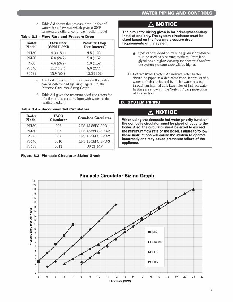
d. Table 3.3 shows the pressure drop (in feet ofwater) for a flow rate which gives a 20°Ftemperature difference for each boiler model.
e. The boiler pressure drop for various flow ratescan be determined by using Figure 3.2, thePinnacle Circulator Sizing Graph.
f. Table 3.4 gives the recommended circulators fora boiler on a secondary loop with water as theheating medium.
g. Special consideration must be given if anti-freezeis to be used as a heating medium. Propyleneglycol has a higher viscosity than water; thereforethe system pressure drop will be higher.
11. Indirect Water Heater: An indirect water heatershould be piped in a dedicated zone. It consists of awater tank that is heated by boiler water passingthrough an internal coil. Examples of indirect waterheating are shown in the System Piping subsectionof this Section.
D. SYSTEM PIPING
WATER PIPING AND CONTROLS
Table 3.3 – Flow Rate and Pressure Drop
Boiler Model
Flow Rate(GPM [LPM])
Pressure Drop(Feet [meters])
PI-T50 4.0 (15.1) 4.5 (1.22)PI-T80 6.4 (24.2) 5.0 (1.52)PI-80 6.4 (24.2) 5.0 (1.52)
PI-140 11.2 (42.4) 8.0 (2.44)PI-199 15.9 (60.2) 13.0 (4.02)
Table 3.4 – Recommended Circulators
Boiler Model
TACOCirculator Grundfos Circulator
PI-T50 006 UPS 15-58FC SPD-1PI-T80 007 UPS 15-58FC SPD-2PI-80 007 UPS 15-58FC SPD-2
PI-140 0010 UPS 15-58FC SPD-3PI-199 0011 UP 26-64F
Pinnacle Circulator Sizing Graph
0
1
2
3
4
5
6
7
8
9
10
11
12
13
14
15
16
17
18
19
20
21
3 4 5 6 7 8 9 10 11 12 13 14 15 16 17 18 19 20 21 22
Flow Rate (GPM)
Pre
ss
ure
Dro
p (
Fe
et
of
He
ad
)
PI-T50
PI-T80/80
PI-140
PI-199
Figure 3.2: Pinnacle Circulator Sizing Graph
When using the domestic hot water priority function,the domestic circulator must be piped directly to theboiler. Also, the circulator must be sized to exceedthe minimum flow rate of the boiler. Failure to followthese instructions will cause the system to operateincorrectly and may cause premature failure of theappliance.
NOTICE
The circulator sizing given is for primary/secondaryinstallations only. The system circulators must besized based on the flow and pressure droprequirements of the system.
NOTICE
8
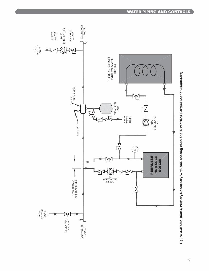
1. Figure 3.3 shows a single boiler with one heatingzone and a Peerless Partner indirect water heater.
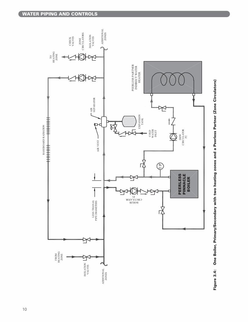
2. Figure 3.4 shows a single boiler with an additionalzone in which baseboard radiation is the heat load.
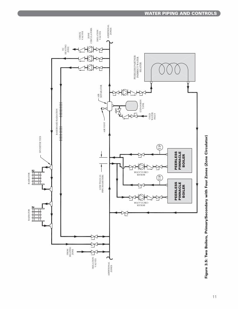
3. Figure 3.5 shows diverter tees used in combinationwith conventional hydronic radiators on anadditional zone. A second boiler is also added to thesystem. Notice that the boilers are piped in parallelon the secondary loop. It is important that thecommon headers are sized to match the systempiping. Smaller headers may result in flowfluctuations through the boilers.
4. Figure 3.6 shows a system in which several differenttypes of loads and multiple boilers are shown. Thissystem illustrates how different temperature zones canbe supplied from the same source by mixing down thetemperature using a three way mixing valve. Radiantflooring typically requires much lower temperaturesthan baseboard radiation and indirect water heating.Notice that a third boiler is included in this system.
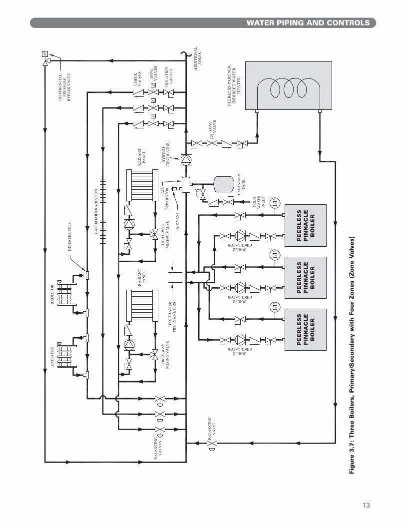
5. Figure 3.7 shows zone valves used in place of zonecirculators. Notice that this system utilizes reversereturn piping which makes it easier to balance thesystem. If the heating zones are very different inlength, the balancing valves on the return side ofeach loop are required.
E. FREEZE PROTECTION
1. Glycol for hydronic applications is speciallyformulated for this purpose. It includes inhibitorswhich prevent the glycol from attacking metallicsystem components. Make certain that the systemfluid is checked for the correct glycol concentrationand inhibitor level.
2. Use only inhibited propylene glycol solutions of upto 50% by volume. Ethylene glycol is toxic and canchemically attack gaskets and seals used in hydronicsystems.
3. The antifreeze solution should be tested at least onceper year and as recommended by the antifreezemanufacturer.
Antifreeze solutions expand more than water. Forexample, a 50% by volume solution expands 4.8%for a 148°F temperature rise while water expandsabout 3% for the same temperature increase.Allowance for this expansion must be considered insizing expansion tanks and related components.
4. The flow rate in systems utilizing glycol solutionshould be increased compared with a water systemto compensate for increased heating capacity.
5. Due to increased flow rate and fluid viscosity thecirculator head requirement will increase. Contact thepump manufacturer to correctly size the circulator fora particular application based on the glycolconcentration and heating requirements.
6. A strainer, sediment trap, or some other means forcleaning the piping system must be provided. It shouldbe located in the return line upstream of the boilerand must be cleaned frequently during the initialoperation of the system. Glycol solution is likely toremove mill scale from new pipe in new installations.
7. Glycol solution is expensive and leaks should beavoided. Weld or solder joints should be used wherepossible and threaded joints should be avoided.Make up water should not be added to the systemautomatically when a glycol solution is used. Addingmake-up water may significantly dilute the system.
8. Check local regulations to see if systems containingglycol solutions must include a back-flow preventeror require that the glycol system be isolated from thewater supply.
9. Do not use galvanized pipe in glycol systems.
10. Use water that is low in mineral content and makesure there are no petroleum products in the solution.
11. Mix solution at room temperature.
12. Do not use a chromate treatment.
13. Do not use glycol solution in a system that mayreach temperatures above 250°F.
14. Refer to Technical Topics, #2a published by theHydronics Institute Division of GAMA for furtherglycol system considerations.
F. SPECIAL APPLICATIONS
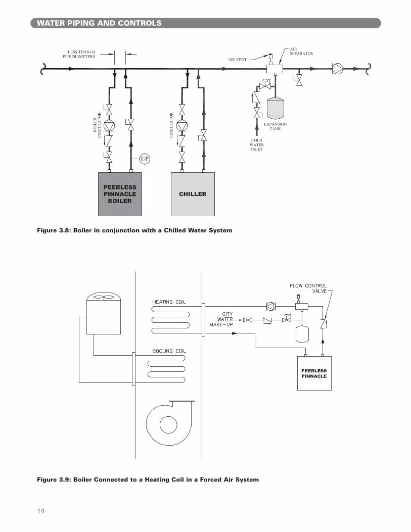
1. If the boiler is used in conjunction with a chilledmedium system, pipe the chiller in a separatesecondary loop.a. Assure that the boiler circulator is disabled during
chiller operation so chilled water does not enterthe boiler.
b. Install a flow control valve (spring check valve) toprevent gravity flow through the boiler.
c. See figure 3.8 for recommended system piping.
2. For boilers connected to heating coils in a forced airsystem where they may be exposed to chilled aircirculation, install flow control valves or other automaticmeans to prevent gravity circulation of the boiler waterduring cooling cycles. See figure 3.9 for illustration.
WATER PIPING AND CONTROLS
When applying multiple boilers, a sequencing controlsuch as the tekmar 265 or the Heat Timer Mini-Mod,should be used. These controls provide control forboiler temperature and domestic circulator operation.
NOTICE
9
Fig
ure
3.3
:O
ne B
oiler,
Pri
mary
/Seco
ndary
wit
h o
ne h
eati
ng z
one a
nd a
Peerl
ess
Part
ner
(Zone C
ircu
lato
rs)
WATER PIPING AND CONTROLS
10
Fig
ure
3.4
:O
ne B
oiler,
Pri
mary
/Seco
ndary
wit
h t
wo h
eati
ng z
ones
and a
Peerl
ess
Part
ner
(Zone C
ircu
lato
rs)
WATER PIPING AND CONTROLS
11
Fig
ure
3.5
:Tw
o B
oilers
, P
rim
ary
/Seco
ndary
wit
h F
our
Zones
(Zone C
ircu
lato
r)
WATER PIPING AND CONTROLS

12
Fig
ure
3.6
:Thre
e B
oilers
, P
rim
ary
/Seco
ndary
wit
h F
ive Z
ones
(Zone C
ircu
lato
r)
WATER PIPING AND CONTROLS
13
WATER PIPING AND CONTROLS
Fig
ure
3.7
:Thre
e B
oilers
, P
rim
ary
/Seco
ndary
wit
h F
our
Zones
(Zone V
alv
es)
14
WATER PIPING AND CONTROLS
Figure 3.8: Boiler in conjunction with a Chilled Water System
Figure 3.9: Boiler Connected to a Heating Coil in a Forced Air System
15
GAS PIPING
A . GENERAL
1. All fuel piping to the boiler is to be in accordancewith local codes. In the absence of local regulationsrefer to the National Fuel Gas Code, ANSIZ223.1/NFPA 54.
2. Size and install piping to provide a supply of gassufficient to meet the maximum demand of allappliances supplied by the piping.
B. FUEL LINE SIZING
1. The rate of gas to be provided to the boiler can bedetermined by the following:
Obtain the gas heating value from the gas supplier.
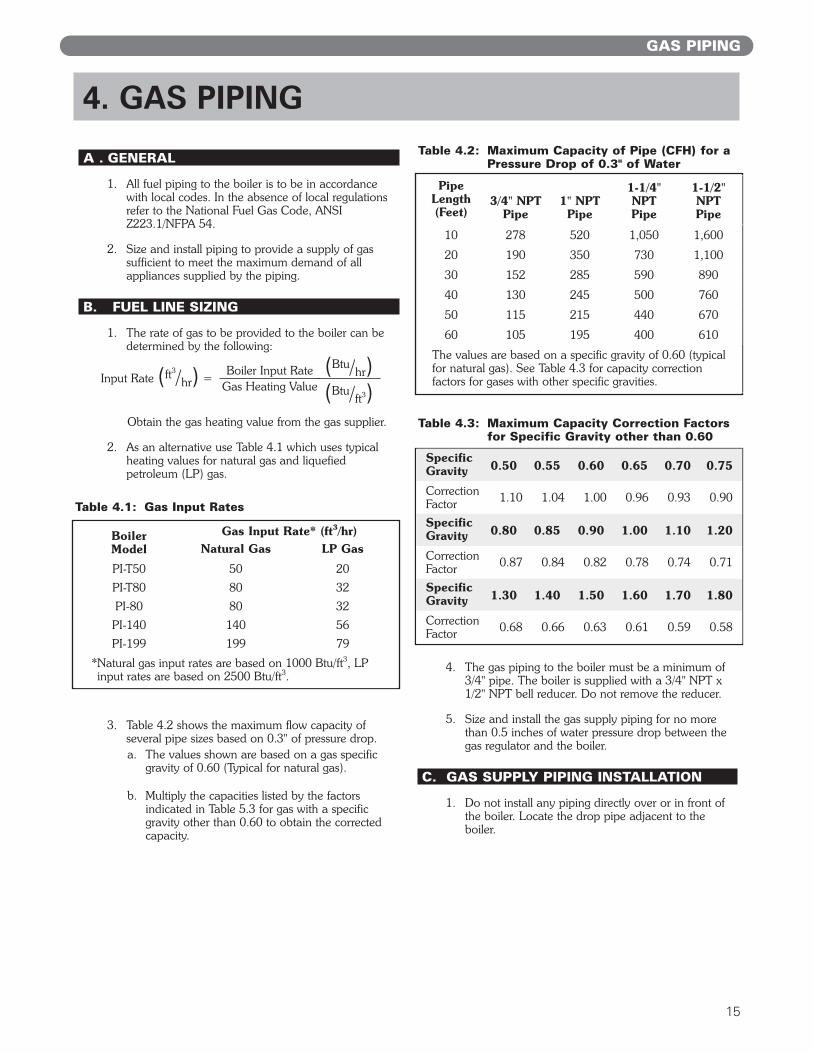
2. As an alternative use Table 4.1 which uses typicalheating values for natural gas and liquefiedpetroleum (LP) gas.
3. Table 4.2 shows the maximum flow capacity ofseveral pipe sizes based on 0.3" of pressure drop.a. The values shown are based on a gas specific
gravity of 0.60 (Typical for natural gas).
b. Multiply the capacities listed by the factorsindicated in Table 5.3 for gas with a specificgravity other than 0.60 to obtain the correctedcapacity.
4. The gas piping to the boiler must be a minimum of3/4" pipe. The boiler is supplied with a 3/4" NPT x1/2" NPT bell reducer. Do not remove the reducer.
5. Size and install the gas supply piping for no morethan 0.5 inches of water pressure drop between thegas regulator and the boiler.
C. GAS SUPPLY PIPING INSTALLATION
1. Do not install any piping directly over or in front ofthe boiler. Locate the drop pipe adjacent to theboiler.
4. GAS PIPING
Boiler Input RateGas Heating Value
Input Rate (ft³/hr) =(Btu/hr)(Btu/ft³)
Boiler Model
Gas Input Rate* (ft³/hr)Natural Gas LP Gas
PI-T50 50 20
PI-T80 80 32
PI-80 80 32
PI-140 140 56
PI-199 199 79
*Natural gas input rates are based on 1000 Btu/ft³, LPinput rates are based on 2500 Btu/ft³.
Pipe Length(Feet)
3/4" NPTPipe
1" NPTPipe
1-1/4"NPTPipe
1-1/2"NPTPipe
10 278 520 1,050 1,600
20 190 350 730 1,100
30 152 285 590 890
40 130 245 500 760
50 115 215 440 670
60 105 195 400 610
The values are based on a specific gravity of 0.60 (typicalfor natural gas). See Table 4.3 for capacity correction factors for gases with other specific gravities.
Table 4.1: Gas Input Rates
Table 4.2: Maximum Capacity of Pipe (CFH) for aPressure Drop of 0.3" of Water
Table 4.3: Maximum Capacity Correction Factorsfor Specific Gravity other than 0.60
Specific Gravity 0.50 0.55 0.60 0.65 0.70 0.75
CorrectionFactor 1.10 1.04 1.00 0.96 0.93 0.90
Specific Gravity 0.80 0.85 0.90 1.00 1.10 1.20
CorrectionFactor 0.87 0.84 0.82 0.78 0.74 0.71
Specific Gravity 1.30 1.40 1.50 1.60 1.70 1.80
CorrectionFactor 0.68 0.66 0.63 0.61 0.59 0.58
16
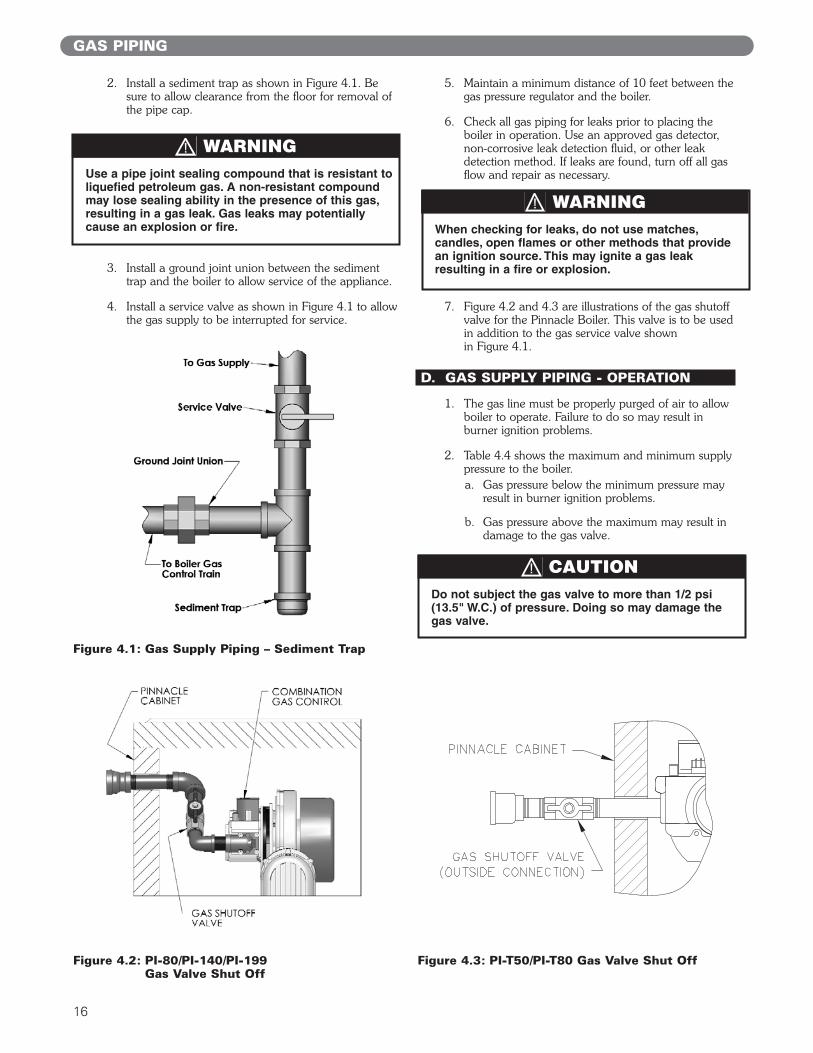
2. Install a sediment trap as shown in Figure 4.1. Besure to allow clearance from the floor for removal ofthe pipe cap.
3. Install a ground joint union between the sedimenttrap and the boiler to allow service of the appliance.
4. Install a service valve as shown in Figure 4.1 to allowthe gas supply to be interrupted for service.
5. Maintain a minimum distance of 10 feet between thegas pressure regulator and the boiler.
6. Check all gas piping for leaks prior to placing theboiler in operation. Use an approved gas detector,non-corrosive leak detection fluid, or other leakdetection method. If leaks are found, turn off all gasflow and repair as necessary.
7. Figure 4.2 and 4.3 are illustrations of the gas shutoff valve for the Pinnacle Boiler. This valve is to be usedin addition to the gas service valve shown in Figure 4.1.
D. GAS SUPPLY PIPING - OPERATION
1. The gas line must be properly purged of air to allowboiler to operate. Failure to do so may result inburner ignition problems.
2. Table 4.4 shows the maximum and minimum supplypressure to the boiler. a. Gas pressure below the minimum pressure may
result in burner ignition problems.
b. Gas pressure above the maximum may result indamage to the gas valve.
GAS PIPING
Do not subject the gas valve to more than 1/2 psi(13.5" W.C.) of pressure. Doing so may damage thegas valve.
CAUTION
Use a pipe joint sealing compound that is resistant toliquefied petroleum gas. A non-resistant compoundmay lose sealing ability in the presence of this gas,resulting in a gas leak. Gas leaks may potentiallycause an explosion or fire.
WARNING
When checking for leaks, do not use matches,candles, open flames or other methods that providean ignition source. This may ignite a gas leakresulting in a fire or explosion.
WARNING
Figure 4.1: Gas Supply Piping – Sediment Trap
Figure 4.2: PI-80/PI-140/PI-199 Gas Valve Shut Off
Figure 4.3: PI-T50/PI-T80 Gas Valve Shut Off
17
3. To check the gas supply pressure on the gas valve:a. Turn off the power at the service switch.
b. Turn off the gas shutoff valve.
c. Using a flat screwdriver, turn the screw inside theinlet pressure tap fitting (see figure 4.4 and 4.5)one turn counterclockwise.
d. Attach the manometer tube to the pressure tapfitting.
e. Open the gas shutoff valve and start the boiler.
f. Read and record the gas pressure while the boileris firing.
g. Turn off the boiler and gas shutoff valve
h. Remove the manometer tube from the pressuretap fitting and turn the screw to close the internalvalve.
i. Turn on the gas shutoff valve and boiler serviceswitch.
4. All gas piping must be leak tested prior to placing theboiler in operation.a. If the leak test pressure requirement is higher
than the maximum inlet pressure noted in Table4.4, the boiler must be isolated from the gassupply piping system.
b. If the gas valve is exposed to pressures exceeding13.5" of water, the gas valve must be replaced.
5. Install the boiler such that the gas ignition systemcomponents are protected from water (dripping,spraying, rain, etc) during operation and service(circulator replacement, condensate trap cleanout,and control replacement, etc).
E. MAIN GAS VALVE - OPERATION
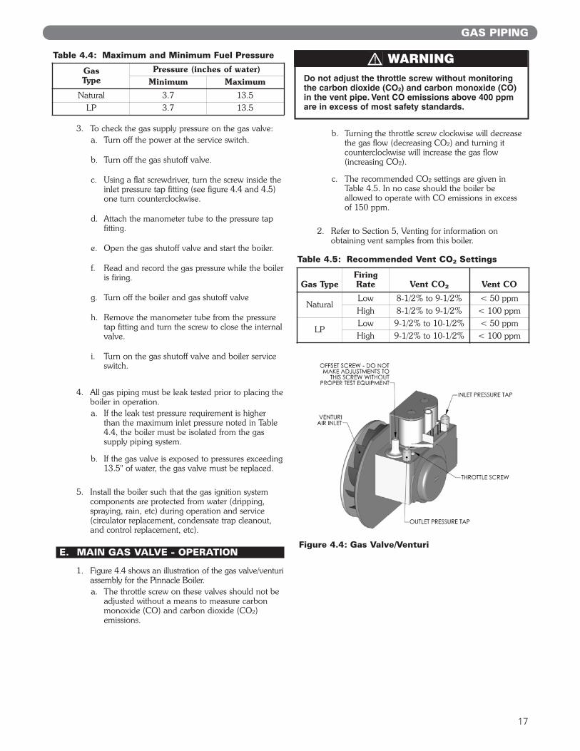
1. Figure 4.4 shows an illustration of the gas valve/venturiassembly for the Pinnacle Boiler.a. The throttle screw on these valves should not be
adjusted without a means to measure carbonmonoxide (CO) and carbon dioxide (CO²)emissions.
b. Turning the throttle screw clockwise will decreasethe gas flow (decreasing CO²) and turning itcounterclockwise will increase the gas flow(increasing CO²).
c. The recommended CO² settings are given inTable 4.5. In no case should the boiler beallowed to operate with CO emissions in excessof 150 ppm.
2. Refer to Section 5, Venting for information onobtaining vent samples from this boiler.
GAS PIPING
Do not adjust the throttle screw without monitoringthe carbon dioxide (CO²) and carbon monoxide (CO)in the vent pipe. Vent CO emissions above 400 ppmare in excess of most safety standards.
WARNINGGas Type
Pressure (inches of water)Minimum Maximum
Natural 3.7 13.5LP 3.7 13.5
Table 4.4: Maximum and Minimum Fuel Pressure
Gas TypeFiring Rate Vent CO² Vent CO
NaturalLow 8-1/2% to 9-1/2% < 50 ppmHigh 8-1/2% to 9-1/2% < 100 ppm
LPLow 9-1/2% to 10-1/2% < 50 ppmHigh 9-1/2% to 10-1/2% < 100 ppm
Table 4.5: Recommended Vent CO² Settings
Figure 4.4: Gas Valve/Venturi
18
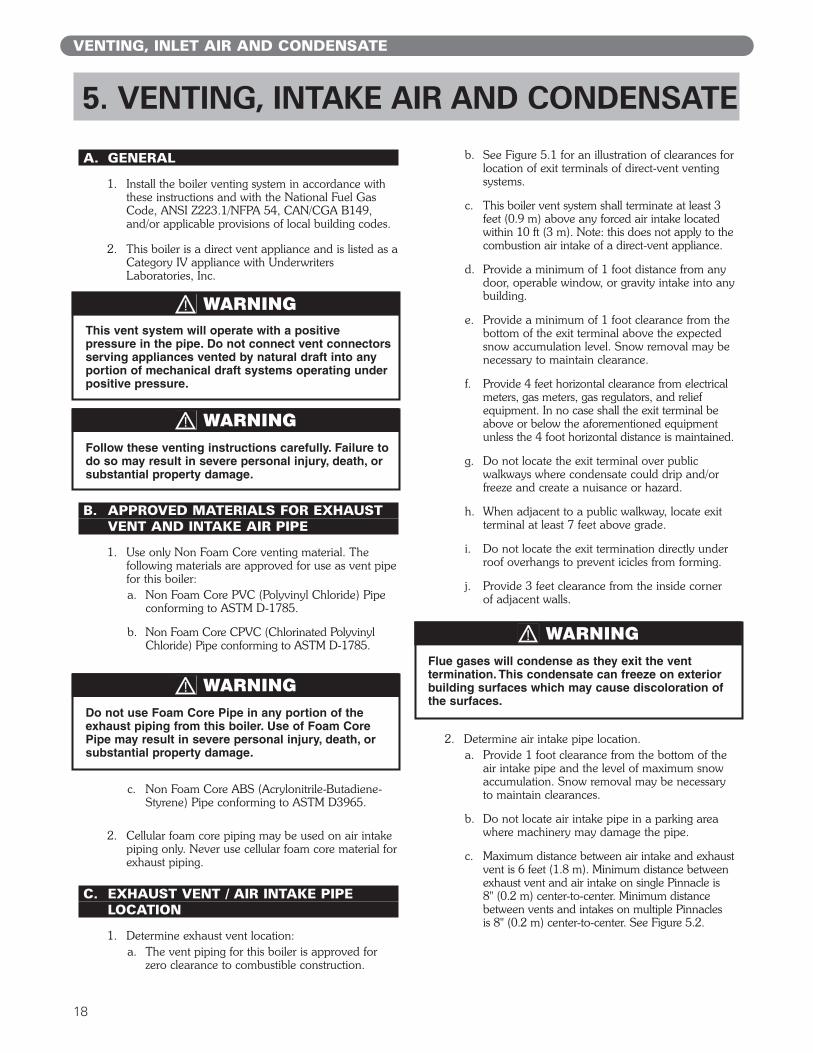
A. GENERAL
1. Install the boiler venting system in accordance withthese instructions and with the National Fuel GasCode, ANSI Z223.1/NFPA 54, CAN/CGA B149,and/or applicable provisions of local building codes.
2. This boiler is a direct vent appliance and is listed as aCategory IV appliance with UnderwritersLaboratories, Inc.
B. APPROVED MATERIALS FOR EXHAUSTVENT AND INTAKE AIR PIPE
1. Use only Non Foam Core venting material. Thefollowing materials are approved for use as vent pipefor this boiler:a. Non Foam Core PVC (Polyvinyl Chloride) Pipe
conforming to ASTM D-1785.
b. Non Foam Core CPVC (Chlorinated PolyvinylChloride) Pipe conforming to ASTM D-1785.
c. Non Foam Core ABS (Acrylonitrile-Butadiene-Styrene) Pipe conforming to ASTM D3965.
2. Cellular foam core piping may be used on air intakepiping only. Never use cellular foam core material forexhaust piping.
C. EXHAUST VENT / AIR INTAKE PIPE LOCATION
1. Determine exhaust vent location:a. The vent piping for this boiler is approved for
zero clearance to combustible construction.
b. See Figure 5.1 for an illustration of clearances forlocation of exit terminals of direct-vent ventingsystems.
c. This boiler vent system shall terminate at least 3feet (0.9 m) above any forced air intake locatedwithin 10 ft (3 m). Note: this does not apply to thecombustion air intake of a direct-vent appliance.
d. Provide a minimum of 1 foot distance from anydoor, operable window, or gravity intake into anybuilding.
e. Provide a minimum of 1 foot clearance from thebottom of the exit terminal above the expectedsnow accumulation level. Snow removal may benecessary to maintain clearance.
f. Provide 4 feet horizontal clearance from electricalmeters, gas meters, gas regulators, and reliefequipment. In no case shall the exit terminal beabove or below the aforementioned equipmentunless the 4 foot horizontal distance is maintained.
g. Do not locate the exit terminal over publicwalkways where condensate could drip and/orfreeze and create a nuisance or hazard.
h. When adjacent to a public walkway, locate exitterminal at least 7 feet above grade.
i. Do not locate the exit termination directly underroof overhangs to prevent icicles from forming.
j. Provide 3 feet clearance from the inside cornerof adjacent walls.
2. Determine air intake pipe location.a. Provide 1 foot clearance from the bottom of the
air intake pipe and the level of maximum snowaccumulation. Snow removal may be necessaryto maintain clearances.
b. Do not locate air intake pipe in a parking areawhere machinery may damage the pipe.
c. Maximum distance between air intake and exhaustvent is 6 feet (1.8 m). Minimum distance betweenexhaust vent and air intake on single Pinnacle is 8" (0.2 m) center-to-center. Minimum distancebetween vents and intakes on multiple Pinnacles is 8" (0.2 m) center-to-center. See Figure 5.2.
VENTING, INLET AIR AND CONDENSATE
5. VENTING, INTAKE AIR AND CONDENSATE
This vent system will operate with a positivepressure in the pipe. Do not connect vent connectorsserving appliances vented by natural draft into anyportion of mechanical draft systems operating underpositive pressure.
WARNING
Follow these venting instructions carefully. Failure todo so may result in severe personal injury, death, orsubstantial property damage.
WARNING
Do not use Foam Core Pipe in any portion of theexhaust piping from this boiler. Use of Foam CorePipe may result in severe personal injury, death, orsubstantial property damage.
WARNINGFlue gases will condense as they exit the venttermination. This condensate can freeze on exteriorbuilding surfaces which may cause discoloration ofthe surfaces.
WARNING
19
VENTING, INTAKE AIR AND CONDENSATE
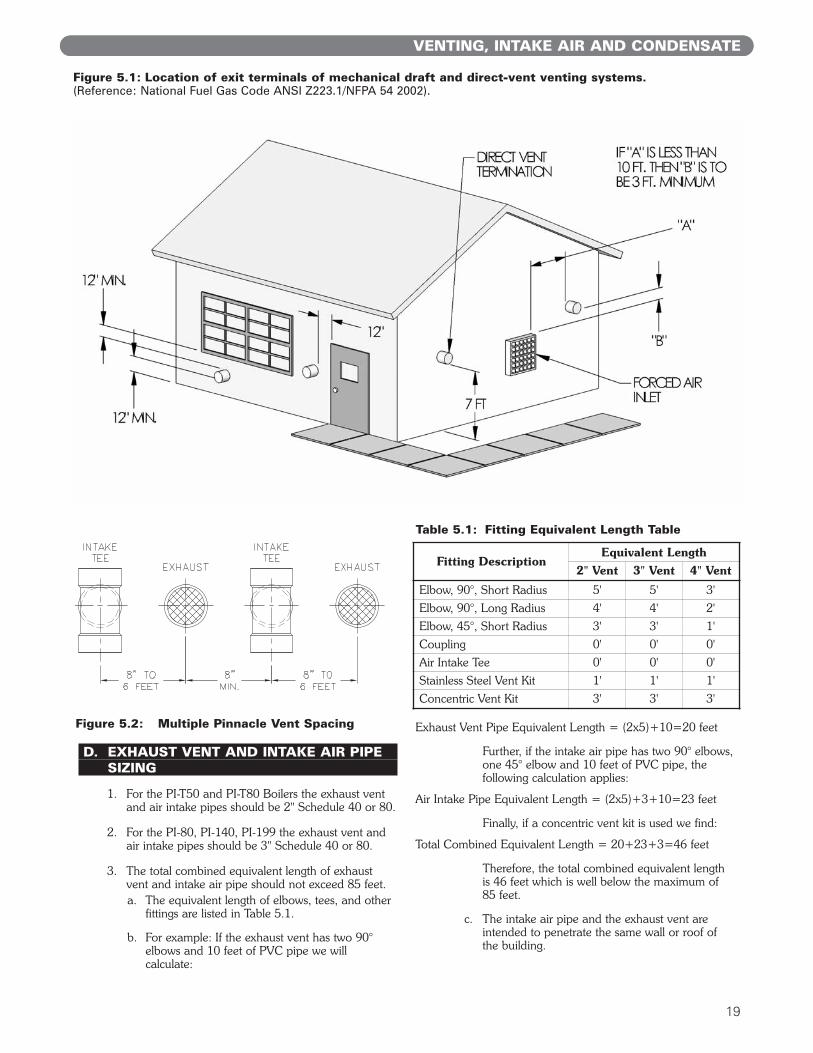
D. EXHAUST VENT AND INTAKE AIR PIPE SIZING
1. For the PI-T50 and PI-T80 Boilers the exhaust ventand air intake pipes should be 2" Schedule 40 or 80.
2. For the PI-80, PI-140, PI-199 the exhaust vent andair intake pipes should be 3" Schedule 40 or 80.
3. The total combined equivalent length of exhaustvent and intake air pipe should not exceed 85 feet.a. The equivalent length of elbows, tees, and other
fittings are listed in Table 5.1.
b. For example: If the exhaust vent has two 90°elbows and 10 feet of PVC pipe we willcalculate:
Exhaust Vent Pipe Equivalent Length = (2x5)+10=20 feet
Further, if the intake air pipe has two 90° elbows,one 45° elbow and 10 feet of PVC pipe, thefollowing calculation applies:
Air Intake Pipe Equivalent Length = (2x5)+3+10=23 feet
Finally, if a concentric vent kit is used we find:
Total Combined Equivalent Length = 20+23+3=46 feet
Therefore, the total combined equivalent lengthis 46 feet which is well below the maximum of85 feet.
c. The intake air pipe and the exhaust vent areintended to penetrate the same wall or roof ofthe building.
Figure 5.1: Location of exit terminals of mechanical draft and direct-vent venting systems.(Reference: National Fuel Gas Code ANSI Z223.1/NFPA 54 2002).
Fitting DescriptionEquivalent Length
2" Vent 3" Vent 4" Vent
Elbow, 90°, Short Radius 5' 5' 3'
Elbow, 90°, Long Radius 4' 4' 2'
Elbow, 45°, Short Radius 3' 3' 1'
Coupling 0' 0' 0'
Air Intake Tee 0' 0' 0'
Stainless Steel Vent Kit 1' 1' 1'
Concentric Vent Kit 3' 3' 3'
Table 5.1: Fitting Equivalent Length Table
Figure 5.2: Multiple Pinnacle Vent Spacing
d. Effort should be made to keep a minimumdifference in equivalent length between the airintake pipe and the exhaust vent.
4. The minimum combined equivalent length is 16equivalent feet.
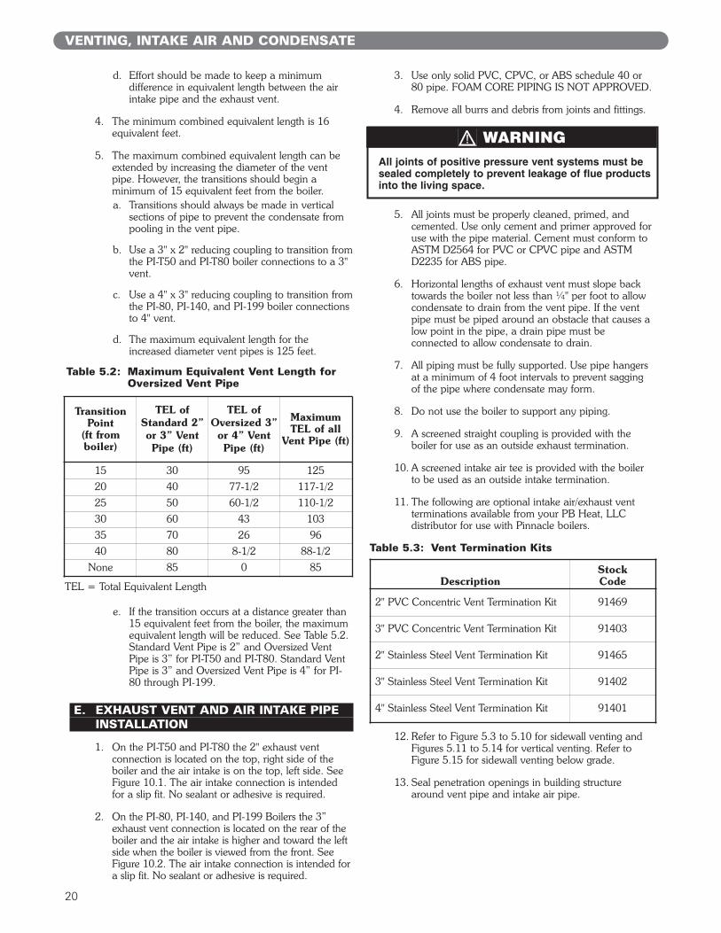
5. The maximum combined equivalent length can beextended by increasing the diameter of the ventpipe. However, the transitions should begin aminimum of 15 equivalent feet from the boiler.a. Transitions should always be made in vertical
sections of pipe to prevent the condensate frompooling in the vent pipe.
b. Use a 3" x 2" reducing coupling to transition fromthe PI-T50 and PI-T80 boiler connections to a 3"vent.
c. Use a 4" x 3" reducing coupling to transition fromthe PI-80, PI-140, and PI-199 boiler connectionsto 4" vent.
d. The maximum equivalent length for theincreased diameter vent pipes is 125 feet.
e. If the transition occurs at a distance greater than15 equivalent feet from the boiler, the maximumequivalent length will be reduced. See Table 5.2.Standard Vent Pipe is 2” and Oversized VentPipe is 3” for PI-T50 and PI-T80. Standard VentPipe is 3” and Oversized Vent Pipe is 4” for PI-80 through PI-199.
E. EXHAUST VENT AND AIR INTAKE PIPE INSTALLATION
1. On the PI-T50 and PI-T80 the 2" exhaust ventconnection is located on the top, right side of theboiler and the air intake is on the top, left side. SeeFigure 10.1. The air intake connection is intendedfor a slip fit. No sealant or adhesive is required.
2. On the PI-80, PI-140, and PI-199 Boilers the 3”exhaust vent connection is located on the rear of theboiler and the air intake is higher and toward the leftside when the boiler is viewed from the front. SeeFigure 10.2. The air intake connection is intended fora slip fit. No sealant or adhesive is required.
3. Use only solid PVC, CPVC, or ABS schedule 40 or80 pipe. FOAM CORE PIPING IS NOT APPROVED.
4. Remove all burrs and debris from joints and fittings.
5. All joints must be properly cleaned, primed, andcemented. Use only cement and primer approved foruse with the pipe material. Cement must conform toASTM D2564 for PVC or CPVC pipe and ASTMD2235 for ABS pipe.
6. Horizontal lengths of exhaust vent must slope backtowards the boiler not less than ¼" per foot to allowcondensate to drain from the vent pipe. If the ventpipe must be piped around an obstacle that causes alow point in the pipe, a drain pipe must beconnected to allow condensate to drain.
7. All piping must be fully supported. Use pipe hangersat a minimum of 4 foot intervals to prevent saggingof the pipe where condensate may form.
8. Do not use the boiler to support any piping.
9. A screened straight coupling is provided with theboiler for use as an outside exhaust termination.
10. A screened intake air tee is provided with the boilerto be used as an outside intake termination.
11. The following are optional intake air/exhaust ventterminations available from your PB Heat, LLCdistributor for use with Pinnacle boilers.
12. Refer to Figure 5.3 to 5.10 for sidewall venting andFigures 5.11 to 5.14 for vertical venting. Refer toFigure 5.15 for sidewall venting below grade.
13. Seal penetration openings in building structurearound vent pipe and intake air pipe.
VENTING, INTAKE AIR AND CONDENSATE
DescriptionStock Code
2" PVC Concentric Vent Termination Kit 91469
3" PVC Concentric Vent Termination Kit 91403
2" Stainless Steel Vent Termination Kit 91465
3" Stainless Steel Vent Termination Kit 91402
4" Stainless Steel Vent Termination Kit 91401
Table 5.3: Vent Termination Kits
All joints of positive pressure vent systems must besealed completely to prevent leakage of flue productsinto the living space.
WARNING
TransitionPoint
(ft fromboiler)
TEL ofStandard 2”or 3” VentPipe (ft)
TEL ofOversized 3”
or 4” VentPipe (ft)
MaximumTEL of all
Vent Pipe (ft)
15 30 95 125
20 40 77-1/2 117-1/2
25 50 60-1/2 110-1/2
30 60 43 103
35 70 26 96
40 80 8-1/2 88-1/2
None 85 0 85
Table 5.2: Maximum Equivalent Vent Length for Oversized Vent Pipe
TEL = Total Equivalent Length
20
21
VENTING, INTAKE AIR AND CONDENSATE
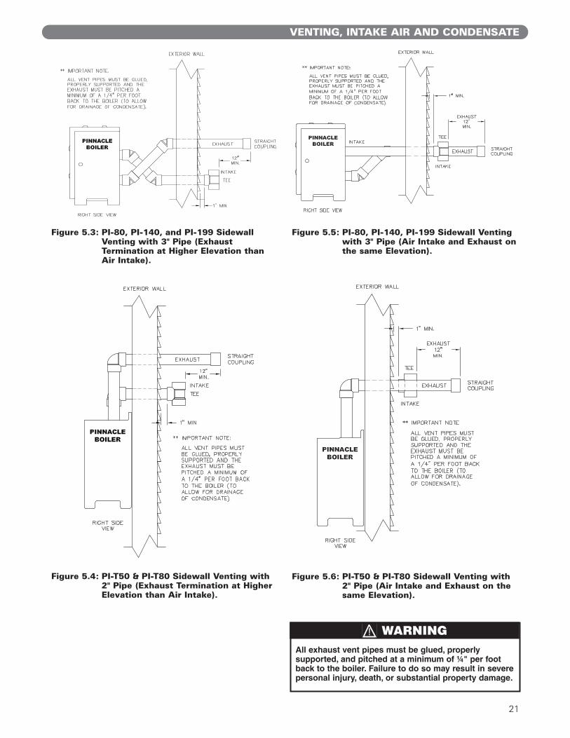
Figure 5.3: PI-80, PI-140, and PI-199 SidewallVenting with 3" Pipe (ExhaustTermination at Higher Elevation thanAir Intake).
Figure 5.5: PI-80, PI-140, PI-199 Sidewall Ventingwith 3" Pipe (Air Intake and Exhaust onthe same Elevation).
Figure 5.4: PI-T50 & PI-T80 Sidewall Venting with2" Pipe (Exhaust Termination at HigherElevation than Air Intake).
Figure 5.6: PI-T50 & PI-T80 Sidewall Venting with2" Pipe (Air Intake and Exhaust on thesame Elevation).
All exhaust vent pipes must be glued, properlysupported, and pitched at a minimum of ¼" per footback to the boiler. Failure to do so may result in severepersonal injury, death, or substantial property damage.
WARNING
22
VENTING, INTAKE AIR AND CONDENSATE
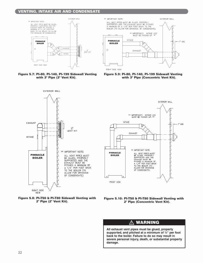
Figure 5.7: PI-80, PI-140, PI-199 Sidewall Ventingwith 3" Pipe (3" Vent Kit).
Figure 5.9: PI-80, PI-140, PI-199 Sidewall Ventingwith 3" Pipe (Concentric Vent Kit).
Figure 5.10: PI-T50 & PI-T80 Sidewall Venting with2" Pipe (Concentric Vent Kit).
All exhaust vent pipes must be glued, properlysupported, and pitched at a minimum of ¼" per footback to the boiler. Failure to do so may result insevere personal injury, death, or substantial propertydamage.
WARNING
Figure 5.8: PI-T50 & PI-T80 Sidewall Venting with2" Pipe (2" Vent Kit).

23
VENTING, INTAKE AIR AND CONDENSATE
Figure 5.11: PI-80, PI-140, PI-199 VerticalVenting with 3" Pipe.
Figure 5.13: PI-80, PI-140, PI-199 VerticalVenting with 3" Pipe (ConcentricVent Kit).
Figure 5.12: PI-T50 & PI-T80 Vertical Ventingwith 2" Pipe.
Figure 5.14: PI-T50 & PI-T80 Vertical Ventingwith 2" Pipe (Concentric Vent Kit).
24
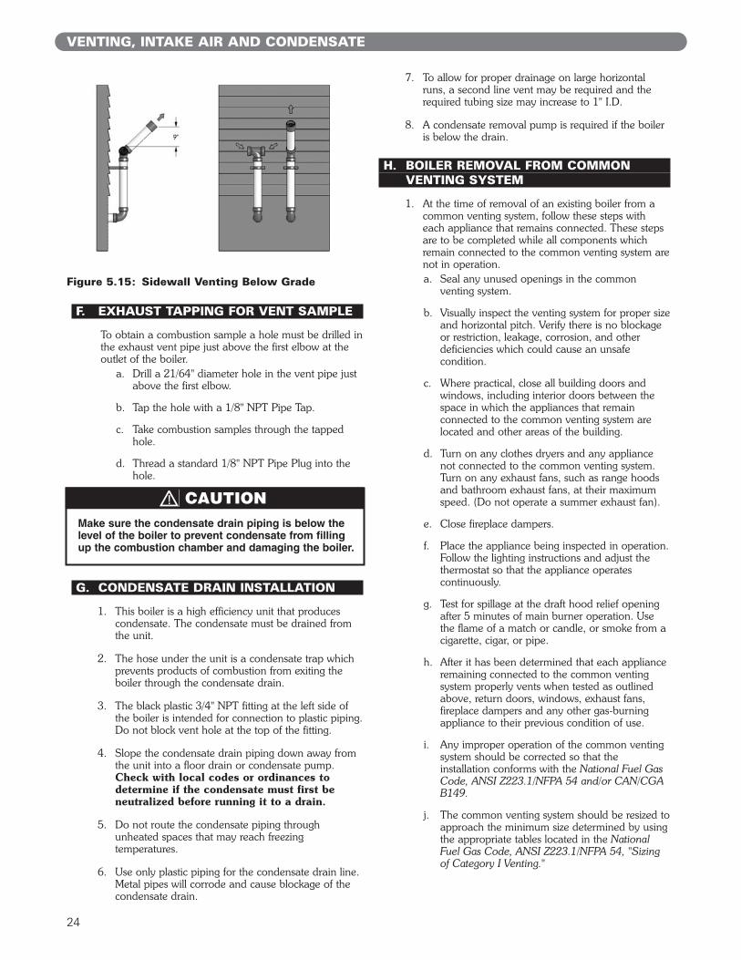
F. EXHAUST TAPPING FOR VENT SAMPLE
To obtain a combustion sample a hole must be drilled inthe exhaust vent pipe just above the first elbow at theoutlet of the boiler.
a. Drill a 21/64" diameter hole in the vent pipe justabove the first elbow.
b. Tap the hole with a 1/8" NPT Pipe Tap.
c. Take combustion samples through the tappedhole.
d. Thread a standard 1/8" NPT Pipe Plug into thehole.
G. CONDENSATE DRAIN INSTALLATION
1. This boiler is a high efficiency unit that producescondensate. The condensate must be drained fromthe unit.
2. The hose under the unit is a condensate trap whichprevents products of combustion from exiting theboiler through the condensate drain.
3. The black plastic 3/4" NPT fitting at the left side ofthe boiler is intended for connection to plastic piping.Do not block vent hole at the top of the fitting.
4. Slope the condensate drain piping down away fromthe unit into a floor drain or condensate pump.Check with local codes or ordinances todetermine if the condensate must first beneutralized before running it to a drain.
5. Do not route the condensate piping throughunheated spaces that may reach freezingtemperatures.
6. Use only plastic piping for the condensate drain line.Metal pipes will corrode and cause blockage of thecondensate drain.
7. To allow for proper drainage on large horizontalruns, a second line vent may be required and therequired tubing size may increase to 1" I.D.
8. A condensate removal pump is required if the boileris below the drain.
H. BOILER REMOVAL FROM COMMON VENTING SYSTEM
1. At the time of removal of an existing boiler from acommon venting system, follow these steps witheach appliance that remains connected. These stepsare to be completed while all components whichremain connected to the common venting system arenot in operation.a. Seal any unused openings in the common
venting system.
b. Visually inspect the venting system for proper sizeand horizontal pitch. Verify there is no blockageor restriction, leakage, corrosion, and otherdeficiencies which could cause an unsafecondition.
c. Where practical, close all building doors andwindows, including interior doors between thespace in which the appliances that remainconnected to the common venting system arelocated and other areas of the building.
d. Turn on any clothes dryers and any appliancenot connected to the common venting system.Turn on any exhaust fans, such as range hoodsand bathroom exhaust fans, at their maximumspeed. (Do not operate a summer exhaust fan).
e. Close fireplace dampers.
f. Place the appliance being inspected in operation.Follow the lighting instructions and adjust thethermostat so that the appliance operatescontinuously.
g. Test for spillage at the draft hood relief openingafter 5 minutes of main burner operation. Usethe flame of a match or candle, or smoke from acigarette, cigar, or pipe.
h. After it has been determined that each applianceremaining connected to the common ventingsystem properly vents when tested as outlinedabove, return doors, windows, exhaust fans,fireplace dampers and any other gas-burningappliance to their previous condition of use.
i. Any improper operation of the common ventingsystem should be corrected so that theinstallation conforms with the National Fuel GasCode, ANSI Z223.1/NFPA 54 and/or CAN/CGAB149.
j. The common venting system should be resized toapproach the minimum size determined by usingthe appropriate tables located in the NationalFuel Gas Code, ANSI Z223.1/NFPA 54, "Sizingof Category I Venting."
VENTING, INTAKE AIR AND CONDENSATE
Make sure the condensate drain piping is below thelevel of the boiler to prevent condensate from fillingup the combustion chamber and damaging the boiler.
CAUTION
Figure 5.15: Sidewall Venting Below Grade
25
ELECTRICAL
6. ELECTRICAL
Install all electrical wiring in accordance with the NationalElectrical Code, ANSI/NFPA 70, and local requirements.
A. WIRING
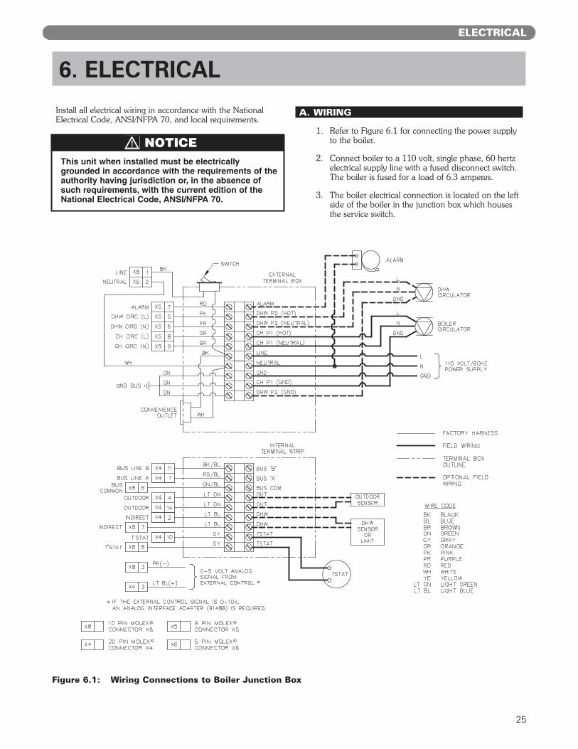
1. Refer to Figure 6.1 for connecting the power supplyto the boiler.
2. Connect boiler to a 110 volt, single phase, 60 hertzelectrical supply line with a fused disconnect switch.The boiler is fused for a load of 6.3 amperes.
3. The boiler electrical connection is located on the leftside of the boiler in the junction box which housesthe service switch.
This unit when installed must be electricallygrounded in accordance with the requirements of theauthority having jurisdiction or, in the absence ofsuch requirements, with the current edition of theNational Electrical Code, ANSI/NFPA 70.
NOTICE
Figure 6.1: Wiring Connections to Boiler Junction Box
26
ELECTRICAL
4. Make sure to maintain correct polarity on the incomingpower supply wires. If polarity is reversed, the boilercontrol will not sense the main burner flame.
5. Connect the ground wire from the incoming powersupply to the green ground screw in the junctionbox. Also, the boiler ground should be connected tothis screw.
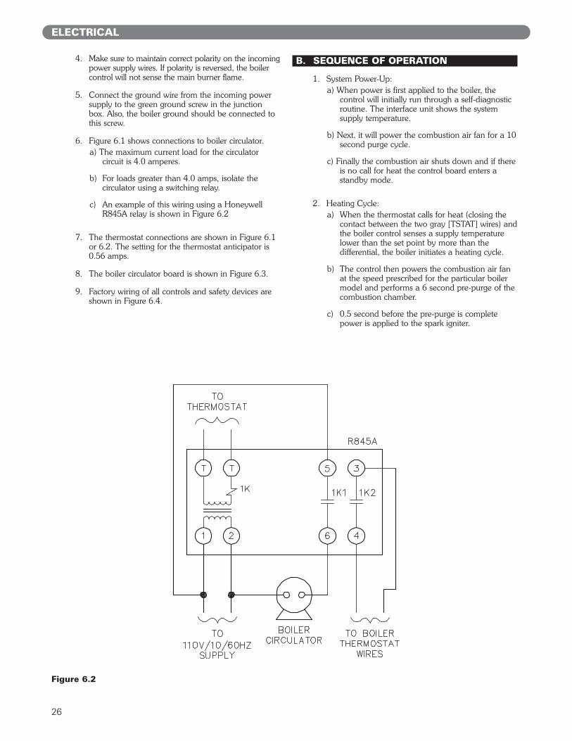
6. Figure 6.1 shows connections to boiler circulator.a) The maximum current load for the circulator
circuit is 4.0 amperes.
b) For loads greater than 4.0 amps, isolate thecirculator using a switching relay.
c) An example of this wiring using a HoneywellR845A relay is shown in Figure 6.2
7. The thermostat connections are shown in Figure 6.1or 6.2. The setting for the thermostat anticipator is0.56 amps.
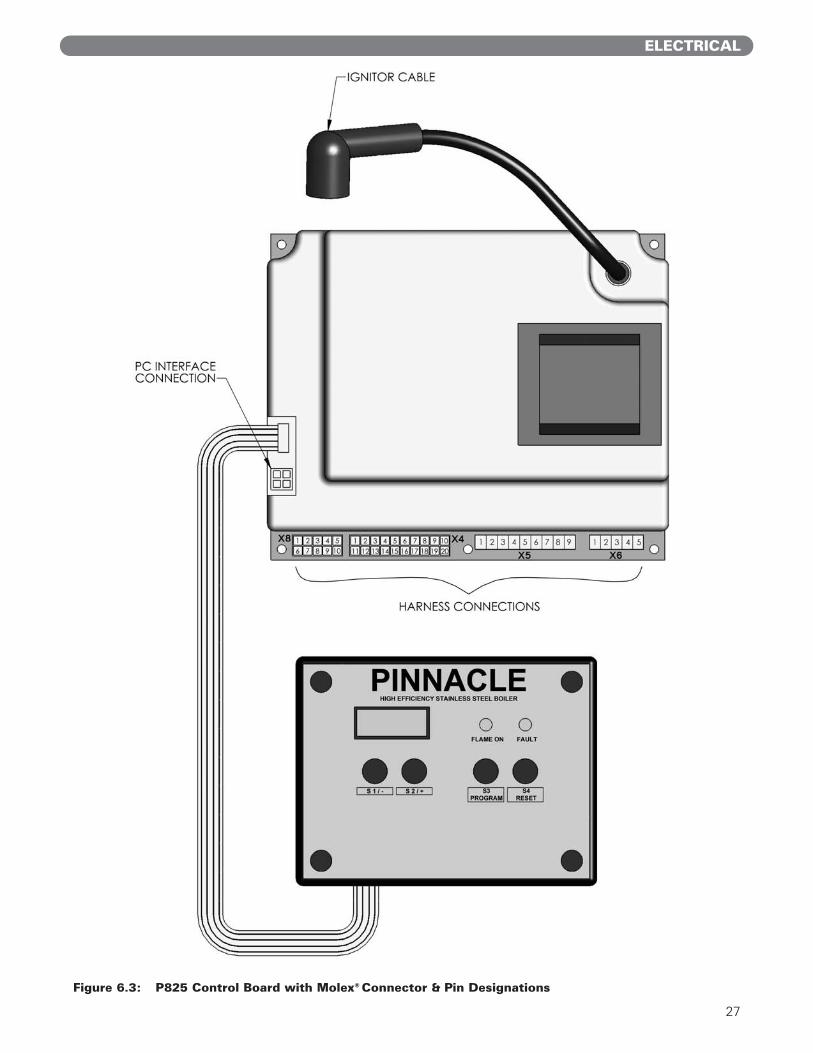
8. The boiler circulator board is shown in Figure 6.3.
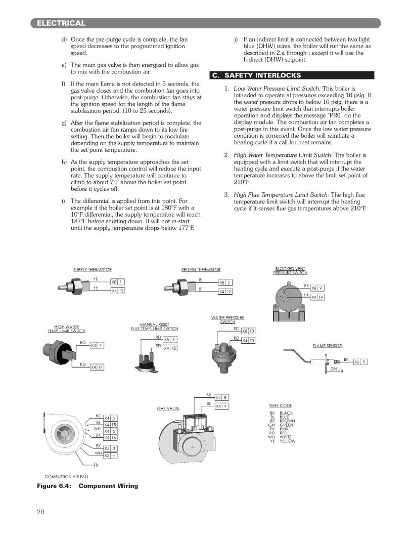
9. Factory wiring of all controls and safety devices areshown in Figure 6.4.
B. SEQUENCE OF OPERATION
1. System Power-Up:a) When power is first applied to the boiler, the
control will initially run through a self-diagnosticroutine. The interface unit shows the systemsupply temperature.
b) Next, it will power the combustion air fan for a 10second purge cycle.
c) Finally the combustion air shuts down and if thereis no call for heat the control board enters astandby mode.
2. Heating Cycle:a) When the thermostat calls for heat (closing the
contact between the two gray [TSTAT] wires) andthe boiler control senses a supply temperaturelower than the set point by more than thedifferential, the boiler initiates a heating cycle.
b) The control then powers the combustion air fanat the speed prescribed for the particular boilermodel and performs a 6 second pre-purge of thecombustion chamber.
c) 0.5 second before the pre-purge is completepower is applied to the spark igniter.
Figure 6.2
27
ELECTRICAL
Figure 6.3: P825 Control Board with Molex® Connector & Pin Designations
28
ELECTRICAL
d) Once the pre-purge cycle is complete, the fanspeed decreases to the programmed ignitionspeed.
e) The main gas valve is then energized to allow gasto mix with the combustion air.
f) If the main flame is not detected in 5 seconds, thegas valve closes and the combustion fan goes intopost-purge. Otherwise, the combustion fan stays atthe ignition speed for the length of the flamestabilization period. (10 to 25 seconds).
g) After the flame stabilization period is complete, thecombustion air fan ramps down to its low firesetting. Then the boiler will begin to modulatedepending on the supply temperature to maintainthe set point temperature.
h) As the supply temperature approaches the setpoint, the combustion control will reduce the inputrate. The supply temperature will continue toclimb to about 7°F above the boiler set pointbefore it cycles off.
i) The differential is applied from this point. Forexample if the boiler set point is at 180°F with a10°F differential, the supply temperature will reach187°F before shutting down. It will not re-startuntil the supply temperature drops below 177°F.
j) If an indirect limit is connected between two lightblue (DHW) wires, the boiler will run the same asdescribed in 2.a through i except it will use theIndirect (DHW) setpoint.
C. SAFETY INTERLOCKS
1. Low Water Pressure Limit Switch: This boiler isintended to operate at pressures exceeding 10 psig. Ifthe water pressure drops to below 10 psig, there is awater pressure limit switch that interrupts boileroperation and displays the message "PR0" on thedisplay module. The combustion air fan completes apost-purge in this event. Once the low water pressurecondition is corrected the boiler will reinitiate aheating cycle if a call for heat remains.
2. High Water Temperature Limit Switch: The boiler isequipped with a limit switch that will interrupt theheating cycle and execute a post-purge if the watertemperature increases to above the limit set point of210°F.
3. High Flue Temperature Limit Switch: The high fluetemperature limit switch will interrupt the heatingcycle if it senses flue gas temperatures above 210°F.
Figure 6.4: Component Wiring
29
ELECTRICAL
4. Blocked Vent Pressure Limit Switch: This switchprevents the boiler from operating if the vent pressureexceeds 1.5 inches water column. This will prevent theboiler from operating if the vent pipe is blocked. Theboiler will indicate "FLU" on the display module.
D. CONTROL FUNCTIONS
1. This Pinnacle boiler is equipped with a P825 ControlBoard. This control board with display module hasthe following functions:a. Shows the boiler supply (outlet) water temperature
on the LED Display as default.
b. Allows user to adjust the supply water set point,the set point differential, and change the displaymode between Fahrenheit and Celsius.
c. Provides Error and Fault Codes on the LEDDisplay.
d. Shows the supply and return temperatures, fanspeed, flame signal (µA), boiler circulator status,boiler set point, total power on hours, boiler onhours, and the number of cycles.
e. Allows manual control of the firing rate using theService Mode.
2. Default Display: Under normal operating conditionsthe default display shows the temperature of the watersupply (boiler outlet) to the system. This may bedisplayed in Fahrenheit or Celsius according to userpreferences.
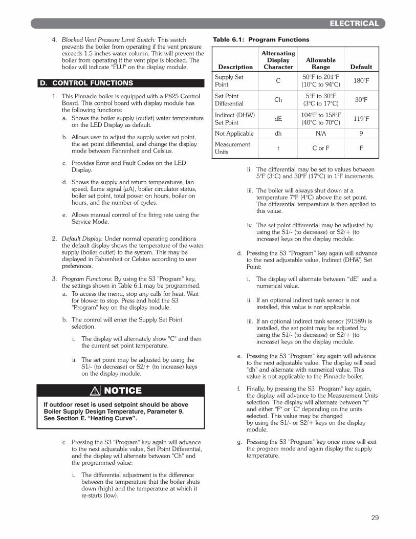
3. Program Functions: By using the S3 "Program" key,the settings shown in Table 6.1 may be programmed.a. To access the menu, stop any calls for heat. Wait
for blower to stop. Press and hold the S3"Program" key on the display module.
b. The control will enter the Supply Set Pointselection.
i. The display will alternately show "C" and thenthe current set point temperature.
ii. The set point may be adjusted by using theS1/- (to decrease) or S2/+ (to increase) keyson the display module.
c. Pressing the S3 "Program" key again will advanceto the next adjustable value, Set Point Differential,and the display will alternate between "Ch" andthe programmed value:
i. The differential adjustment is the differencebetween the temperature that the boiler shutsdown (high) and the temperature at which itre-starts (low).
ii. The differential may be set to values between5°F (3°C) and 30°F (17°C) in 1°F increments.
iii. The boiler will always shut down at atemperature 7°F (4°C) above the set point.The differential temperature is then applied tothis value.
iv. The set point differential may be adjusted byusing the S1/- (to decrease) or S2/+ (toincrease) keys on the display module.
d. Pressing the S3 “Program” key again will advanceto the next adjustable value, Indirect (DHW) SetPoint:
i. The display will alternate between “dE” and anumerical value.
ii. If an optional indirect tank sensor is notinstalled, this value is not applicable.
iii. If an optional indirect tank sensor (91589) isinstalled, the set point may be adjusted byusing the S1/- (to decrease) or S2/+ (toincrease) keys on the display module.
e. Pressing the S3 "Program" key again will advanceto the next adjustable value. The display will read"dh" and alternate with numerical value. Thisvalue is not applicable to the Pinnacle boiler.
f. Finally, by pressing the S3 "Program" key again,the display will advance to the Measurement Unitsselection. The display will alternate between "t"and either "F" or "C" depending on the unitsselected. This value may be changed by using the S1/- or S2/+ keys on the displaymodule.
g. Pressing the S3 "Program" key once more will exitthe program mode and again display the supplytemperature.
Table 6.1: Program Functions
Description
Alternating Display
CharacterAllowable
Range Default
Supply SetPoint
C50°F to 201°F(10°C to 94°C)
180°F
Set PointDifferential
Ch5°F to 30°F
(3°C to 17°C)30°F
Indirect (DHW)Set Point
dE104°F to 158°F(40°C to 70°C)
119°F
Not Applicable dh N/A 9
MeasurementUnits
t C or F F
If outdoor reset is used setpoint should be aboveBoiler Supply Design Temperature, Parameter 9. See Section E. “Heating Curve”.
NOTICE
30
ELECTRICAL
4. Error Codes: The LED Display will display error codesif the boiler is in a temporary fault condition. Table 8.1shows Error Codes and descriptions. In some cases, ifthe temporary fault is not corrected within 60 secondsthe controller will go into a Fault Code.
5. Fault Codes: A Fault Code indicates the controller is locked-out. Press the S4 "Reset" key to resumeoperation after repairing the problem. Table 8.2shows Fault Codes for this control.
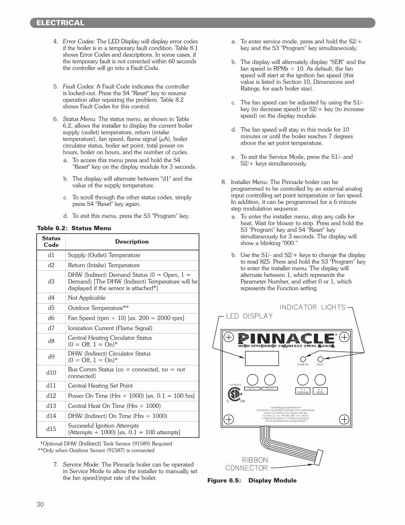
6. Status Menu: The status menu, as shown in Table6.2, allows the installer to display the current boilersupply (outlet) temperature, return (intaketemperature), fan speed, flame signal (µA), boilercirculator status, boiler set point, total power onhours, boiler on hours, and the number of cycles.a. To access this menu press and hold the S4
"Reset" key on the display module for 3 seconds.
b. The display will alternate between "d1" and thevalue of the supply temperature.
c. To scroll through the other status codes, simplypress S4 "Reset" key again.
d. To exit this menu, press the S3 "Program" key.
7. Service Mode: The Pinnacle boiler can be operatedin Service Mode to allow the installer to manually setthe fan speed/input rate of the boiler.
a. To enter service mode, press and hold the S2/+key and the S3 "Program" key simultaneously.
b. The display will alternately display "SER" and thefan speed in RPMs ÷ 10. As default, the fanspeed will start at the ignition fan speed (thisvalue is listed in Section 10, Dimensions andRatings, for each boiler size).
c. The fan speed can be adjusted by using the S1/-key (to decrease speed) or S2/+ key (to increasespeed) on the display module.
d. The fan speed will stay in this mode for 10minutes or until the boiler reaches 7 degreesabove the set point temperature.
e. To exit the Service Mode, press the S1/- andS2/+ keys simultaneously.
8. Installer Menu: The Pinnacle boiler can beprogrammed to be controlled by an external analoginput controlling set point temperature or fan speed.In addition, it can be programmed for a 6 minutestep modulation sequence.a. To enter the installer menu, stop any calls for
heat. Wait for blower to stop. Press and hold theS3 "Program" key and S4 "Reset" keysimultaneously for 3 seconds. The display willshow a blinking "000."
b. Use the S1/- and S2/+ keys to change the displayto read 825. Press and hold the S3 "Program" keyto enter the installer menu. The display willalternate between 1, which represents theParameter Number, and either 0 or 1, whichrepresents the Function setting.
Table 6.2: Status Menu
StatusCode Description
d1 Supply (Outlet) Temperature
d2 Return (Intake) Temperature
d3DHW (Indirect) Demand Status (0 = Open, 1 =Demand) [The DHW (Indirect) Temperature will bedisplayed if the sensor is attached*]
d4 Not Applicable
d5 Outdoor Temperature**
d6 Fan Speed (rpm ÷ 10) [ex. 200 = 2000 rpm]
d7 Ionization Current (Flame Signal)
d8 Central Heating Circulator Status (0 = Off, 1 = On)*
d9 DHW (Indirect) Circulator Status (0 = Off, 1 = On)*
d10 Bus Comm Status (co = connected, no = not connected)
d11 Central Heating Set Point
d12 Power On Time (Hrs ÷ 1000) [ex. 0.1 = 100 hrs]
d13 Central Heat On Time (Hrs ÷ 1000)
d14 DHW (Indirect) On Time (Hrs ÷ 1000)
d15 Successful Ignition Attempts (Attempts ÷ 1000) [ex. 0.1 = 100 attempts]
Figure 6.5: Display Module
*Optional DHW (Indirect) Tank Sensor (91589) Required**Only when Outdoor Sensor (91587) is connected
31
ELECTRICAL
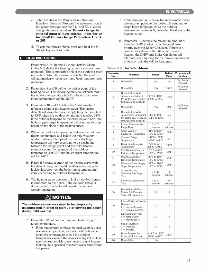
c. Table 6.3 shows the Parameter numbers andFunctions. Press S3 "Program" to advance throughthe parameters and use the S1/- and S2/+keys tochange the function values. Do not change toexternal input without external input deviceinstalled! Do not change Parameters 1, 2, 4or 20!
d. To exit the Installer Menu, press and hold the S4"Reset" key for 3 seconds.
E. HEATING CURVE
1. Parameters 8, 9, 10 and 11 in the Installer Menu(Table 6.3) define the heating curve for outdoor resetoperation. This is applicable only if the outdoor sensoris installed. When this sensor is installed the controlwill automatically recognize it and begin outdoor resetoperation.
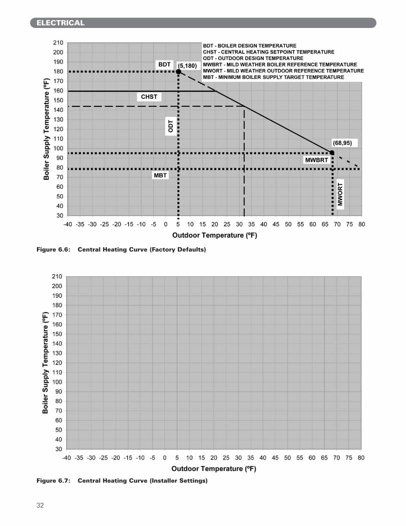
2. Parameters 8 and 9 define the design point of theheating curve. The factory defaults are set such that ifthe outdoor temperature is 5ºF or below, the boilertarget temperature will be 180ºF.
3. Parameters 10 and 11 define the “mild weather”reference point of the heating curve. The factorydefaults will drop the boiler supply target temperatureto 95ºF when the outdoor temperature reaches 68ºF.If the outdoor temperature increases beyond 68ºF theboiler supply target temperature will continue to dropbased on the slope of the heating curve.
4. When the outdoor temperature is above the outdoordesign temperature and below the mild weatheroutdoor reference temperature, the boiler targettemperature will vary according to a straight linebetween the design point and the mild weatherreference point. For example, if the outdoortemperature is at 32ºF the boiler target temperaturewill be 144ºF.
5. Figure 6.6 shows a graph of the heating curve withthe default design and mild weather reference point. It also illustrates how the boiler target temperaturevaries according to outdoor temperature.
6. The heating curve operates only if an outdoor sensoris connected to the boiler. If the outdoor sensor isdisconnected, the boiler will revert to standardsetpoint operation.
7. Parameter 12 defines the minimum boiler supplytarget temperature.• If this temperature is above the mild weather boiler
reference temperature, the boiler will continue totarget this temperature even if the outdoortemperature exceeds the corresponding value. Thismay be used for kick space heaters or unit heatersthat require a specified minimum water temperatureto operate.
• If this temperature is below the mild weather boilerreference temperature, the boiler will continue totarget lower temperatures as the outdoortemperature increases by following the slope of theheating curve.
8. Parameter 14 defines the maximum amount oftime the DHW (Indirect) Circulator will takepriority over the Boiler Circulator. If there is acontinuous call for both indirect and spaceheating, the DHW and Boiler Circulators willalternate, each running for the maximum amountof time or until the call for heat ends.
Table 6.3: Installer Menu
Parameter No. Function Range Default
ValueProgrammed
Setting
1 Unavailable N/A deNo Change
Allowed
2 Unavailable N/A 149°FNo Change
Allowed
3
Domestic Hot WaterTemperature Setpoint (Available only if indirecttank sensor is installed)
95°F to 160°F(35°C to 71°C)
125°F
4 Unavailable N/A 36°FNo Change
Allowed
5
Domestic Hot WaterTemperature Differential (Available only if indirecttank sensor is installed)
1°F to 18°F(1/2°C to 10°C)
7°F
6Indirect Circulator PostPurge Time
0 to 60 minutes
0 minutes
7Warm WeatherShutdown Temperature
41°F to 122°F(5°C to 50°C)
68°F
8Outdoor DesignTemperature
-49°F to 32°F(-45°C to 0°C)
5°F
9Boiler Supply DesignTemperature
77°F to 201°F(25°C to 94°C)
180°F
10Mild Weather OutdoorReference Temperature
32°F to 95°F(0°C to 35°C)
68°F
11Mild Weather BoilerReference Temperature
32°F to 180°F(0°C to 82°C)
95°F
12Minimum Boiler SupplyTarget Temperature
32°F to 180°F(0°C to 82°C)
68°F
13Central HeatingCirculator Post PurgeTime
0 to 10 minutes
0 minutes
14Indirect Maximum RunTime
0 to 60 minutes
30 minutes
15Bus Address [0 ZoneMaster, 1-8 CascadeSlave] (Not Available)
0-8 0
16
Internal/External ControlParameter: 0 = Internal Control; 1 = External Control
0-1 0
17External Input Type: 0 = Temperature; 1 = Modulation %
0-1 0
18Step Modulation: 0 = Disabled; 1 = Enabled
0-1 0
19Boiler Setpoint forIndirect Call for Heat
119°F to 180°F(48°C to 82°C)
180°F
20 Unavailable N/A 1
The outdoor sensor may need to be temporarilydisconnected in order to start up or service the boilerduring mild weather.
NOTICE
32
ELECTRICAL
Figure 6.6: Central Heating Curve (Factory Defaults)
Figure 6.7: Central Heating Curve (Installer Settings)
33
A. COMPLETING THE INSTALLATION
1. Confirm that all water, gas and electricity are turned off.
2. Verify that water piping, venting, gas piping andelectrical wiring and components are installedproperly and where applicable in accordance withmanufacturers' instructions. Be sure that the boiler isinstalled in accordance with this manual and goodengineering practice.
3. Fill the boiler and system with water, making certainto vent all air from each high point in the system.Open each vent in the system until all air is releasedand water begins to be discharged, and then closethe vent.
4. The pressure reducing valve on the fill line willtypically allow the system to be filled and pressurizedto 12 PSI. Consult the manufacturer's instructions foroperation of the valve and expansion tank.
5. Check joints and fittings throughout the system andrepair as required.
6. Connect a manometer at or near the service valve tothe boiler.
7. Confirm that the gas supply pressure to the boiler isbetween the minimum and maximum values for thegas being used. These values can be found in Table4.4 of Section 4.
8. If a supply pressure check is required, isolate theboiler and gas valve before performing the pressuretest. If the supply pressure is too high or too low,contact the fuel gas supplier.
9. Turn on electricity and gas to the boiler. Check to seeif the LED display is lit. The combustion air fan willbegin a 5 second purge cycle and then the controlwill go into Standby Mode.
10. Refer to Section 6, Paragraph D, “ControlFunctions,” for set point and differential settings. Toset the heating curve and advanced functions refer toSection 6, Paragraph E, “Heating Curve.
11. Light the boiler by following the Lighting/Operatinginstructions in this section. The initial ignition mayfail several times before the gas piping is completelypurged of air.
12. Use the sequence of operation description andFigure 6.1, Wiring Connections to Boiler JunctionBox, to follow light off and shutdown sequences andto assist in diagnosing problems. If the boiler doesnot function properly, consult Section 8,Troubleshooting.
13. Refer to subsection 7.C for instructions on setting upthe boiler.
7. START-UP PROCEDURES
START-UP PROCEDURES
34
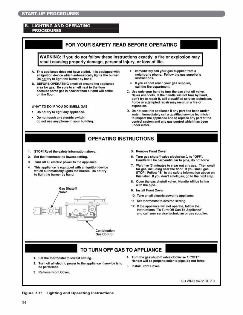
B. LIGHTING AND OPERATINGPROCEDURES
START-UP PROCEDURES
Figure 7.1: Lighting and Operating Instructions
35
START-UP PROCEDURES
C. CHECK-OUT PROCEDUREAfter Starting the boiler, be certain that all controls areworking properly and that combustion is properly set up.
1. Check to be sure that the boiler will shut down whenthe supply water temperature reaches the controlsetpoint.a) Note the boiler set point setting in the program
menu (Table 6.1) or in the status menu, coded11 (Table 6.2).
b) Manually set the boiler to its highest input byentering Service Mode (refer to Section 6.D.7)and pressing the S2/+ key until the displayvalues no longer increase.
c) Monitor the boiler temperature on thetemperature gauge (field mounted in the boilersupply piping).
d) The boiler should shut down at 7ºF above theboiler setpoint. If it does not shut down, contactyour PB Heat Representative. (Note thatdepending on the outdoor reset curve, the boilermay shutdown before the Supply Setpoint ismet).
2. Check the combustion readings in the boiler vent pipe.a) Drill and tap a 1/8" NPT threaded hole in the
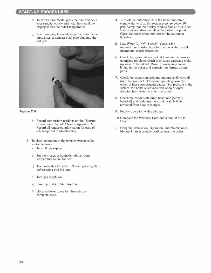
boiler vent pipe within 12 inches (305 mm) ofthe boiler vent connection. (21/64" drill and 1/8"NPT pipe tap are recommended). This is to beused as a combustion test port for thecombustion analyzer. See Figure 7.2.
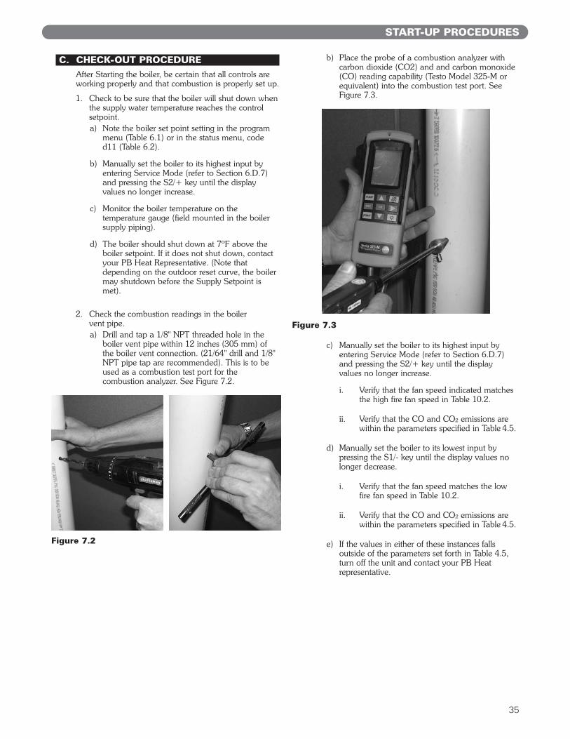
b) Place the probe of a combustion analyzer withcarbon dioxide (CO2) and and carbon monoxide(CO) reading capability (Testo Model 325-M orequivalent) into the combustion test port. SeeFigure 7.3.
c) Manually set the boiler to its highest input byentering Service Mode (refer to Section 6.D.7)and pressing the S2/+ key until the displayvalues no longer increase.
i. Verify that the fan speed indicated matches the high fire fan speed in Table 10.2.
ii. Verify that the CO and CO² emissions are within the parameters specified in Table 4.5.
d) Manually set the boiler to its lowest input bypressing the S1/- key until the display values nolonger decrease.
i. Verify that the fan speed matches the low fire fan speed in Table 10.2.
ii. Verify that the CO and CO² emissions are within the parameters specified in Table 4.5.
e) If the values in either of these instances fallsoutside of the parameters set forth in Table 4.5,turn off the unit and contact your PB Heatrepresentative.
Figure 7.2
Figure 7.3
36
START-UP PROCEDURES
f) To exit Service Mode, press the S1/- and S2/+keys simultaneously and hold them until thedisplay shows the outlet temperature.
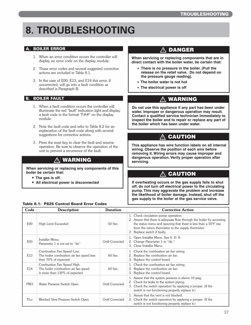
g) After removing the analyzer probe from the ventpipe, insert a stainless steel pipe plug into the test port.
h) Record combustion readings on the “StartupCombustion Record” Sheet in Appendix A.Record all requested information for ease offollow-up and troubleshooting.
3. To check operation of the ignition system safetyshutoff features:a) Turn off gas supply.
b) Set thermostat or controller above roomtemperature to call for heat.
c) The boiler should perform 3 attempts at ignitionbefore going into lock-out.
d) Turn gas supply on.
e) Reset by pushing S4 "Reset" key.
f) Observe boiler operation through one complete cycle.
4. Turn off the automatic fill to the boiler and drain some water to drop the system pressure below 10psig. Verify that the display module reads "PRO" after5 seconds and does not allow the boiler to operate.Close the boiler drain and turn on the automatic fill valve.
5. Low Water Cut-Off (if used) - Consult themanufacturer's instructions for the low water cut-offoperational check procedure.
6. Check the system to assure that there are no leaks oroverfilling problems which may cause excessive makeup water to be added. Make up water may causeliming in the boiler and corrosion in ferrous systemparts.
7. Check the expansion tank and automatic fill valve (ifused) to confirm that they are operating correctly. Ifeither of these components causes high pressure in thesystem, the boiler relief valve will weep or open,allowing fresh water to enter the system.
8. Check the condensate drain hose (and pump ifinstalled) and make sure all condensate is beingremoved from heat exchanger.
9. Review operation with end-user.
10. Complete the Warranty Card and submit it to PBHeat.
11. Hang the Installation, Operation, and MaintenanceManual in an accessible position near the boiler.
Figure 7.4
37
A. BOILER ERROR
1. When an error condition occurs the controller willdisplay an error code on the display module.
2. These error codes and several suggested correctiveactions are included in Table 8.1.
3. In the case of E00, E13, and E14 this error, ifuncorrected, will go into a fault condition asdescribed is Paragraph B.
B. BOILER FAULT
1. When a fault condition occurs the controller willilluminate the red "fault" indication light and displaya fault code in the format "F##" on the displaymodule.
2. Note the fault code and refer to Table 8.2 for anexplanation of the fault code along with severalsuggestions for corrective actions.
3. Press the reset key to clear the fault and resumeoperation. Be sure to observe the operation of theunit to prevent a recurrence of the fault.
8. TROUBLESHOOTING
TROUBLESHOOTING
If overheating occurs or the gas supply fails to shutoff, do not turn off electrical power to the circulatingpump. This may aggravate the problem and increasethe likelihood of boiler damage. Instead, shut off thegas supply to the boiler at the gas service valve.
CAUTION
This appliance has wire function labels on all internalwiring. Observe the position of each wire beforeremoving it. Wiring errors may cause improper anddangerous operation. Verify proper operation afterservicing.
CAUTION
DANGERWhen servicing or replacing components that are indirect contact with the boiler water, be certain that:
● There is no pressure in the boiler. (Pull therelease on the relief valve. Do not depend onthe pressure gauge reading).
● The boiler water is not hot● The electrical power is off
When servicing or replacing any components of thisboiler be certain that:
● The gas is off.● All electrical power is disconnected
WARNING
Do not use this appliance if any part has been underwater. Improper or dangerous operation may result.Contact a qualified service technician immediately toinspect the boiler and to repair or replace any part ofthe boiler which has been under water.
WARNING
Code Description Duration Corrective Action
E00 High Limit Exceeded 50 Sec.
1. Check circulation pump operation.2. Assure that there is adequate flow through the boiler by accessing
the status menu and assuring that there is less than a 50°F risefrom the return thermistor to the supply thermistor.
3. Replace switch if faulty.
E03Installer Menu: Parameter 1 is not set to “de”
Until Corrected1. Open Installer Menu. See 6. D. 8.2. Change Parameter 1 to “de.”3. Close Installer Menu.
E13Combustion Fan Speed Low.The boiler combustion air fan speed lessthan 70% of expected.
60 Sec.1. Check the combustion air fan wiring.2. Replace the combustion air fan.3. Replace the control board.
E14Combustion Fan Speed High.The boiler combustion air fan speed is more than 130% of expected.
60 Sec.1. Check the combustion air fan wiring.2. Replace the combustion air fan.3. Replace the control board.
PRO Water Pressure Switch Open Until Corrected
1. Assure that the system pressure is above 10 psig.2. Check for leaks in the system piping.3. Check the switch operation by applying a jumper. (If the
switch is not functioning properly replace it.)
FLu Blocked Vent Pressure Switch Open Until Corrected1. Assure that the vent is not blocked.2. Check the switch operation by applying a jumper. (If the
switch is not functioning properly replace it.)
Table 8.1: P825 Control Board Error Codes
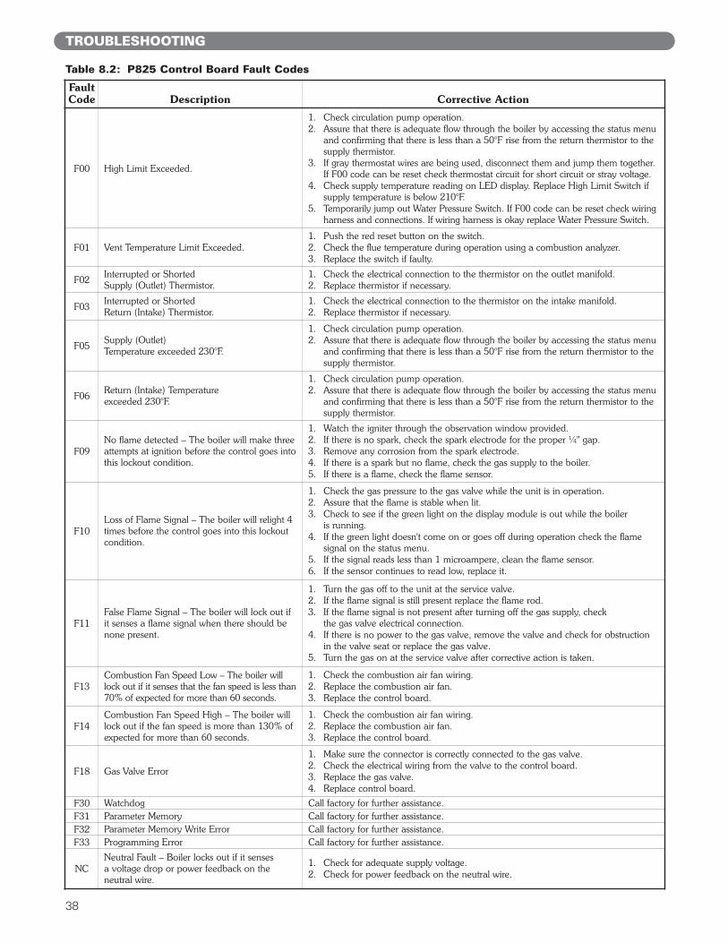
38
FaultCode Description Corrective Action
F00 High Limit Exceeded.
1. Check circulation pump operation.2. Assure that there is adequate flow through the boiler by accessing the status menu
and confirming that there is less than a 50°F rise from the return thermistor to thesupply thermistor.
3. If gray thermostat wires are being used, disconnect them and jump them together. If F00 code can be reset check thermostat circuit for short circuit or stray voltage.
4. Check supply temperature reading on LED display. Replace High Limit Switch if supply temperature is below 210°F.
5. Temporarily jump out Water Pressure Switch. If F00 code can be reset check wiringharness and connections. If wiring harness is okay replace Water Pressure Switch.
F01 Vent Temperature Limit Exceeded.1. Push the red reset button on the switch.2. Check the flue temperature during operation using a combustion analyzer.3. Replace the switch if faulty.
F02Interrupted or Shorted Supply (Outlet) Thermistor.
1. Check the electrical connection to the thermistor on the outlet manifold.2. Replace thermistor if necessary.
F03Interrupted or Shorted Return (Intake) Thermistor.
1. Check the electrical connection to the thermistor on the intake manifold.2. Replace thermistor if necessary.
F05Supply (Outlet) Temperature exceeded 230°F.
1. Check circulation pump operation.2. Assure that there is adequate flow through the boiler by accessing the status menu
and confirming that there is less than a 50°F rise from the return thermistor to thesupply thermistor.
F06Return (Intake) Temperature exceeded 230°F.
1. Check circulation pump operation.2. Assure that there is adequate flow through the boiler by accessing the status menu
and confirming that there is less than a 50°F rise from the return thermistor to thesupply thermistor.
F09No flame detected – The boiler will make threeattempts at ignition before the control goes intothis lockout condition.
1. Watch the igniter through the observation window provided.2. If there is no spark, check the spark electrode for the proper ¼" gap.3. Remove any corrosion from the spark electrode.4. If there is a spark but no flame, check the gas supply to the boiler.5. If there is a flame, check the flame sensor.
F10Loss of Flame Signal – The boiler will relight 4times before the control goes into this lockoutcondition.
1. Check the gas pressure to the gas valve while the unit is in operation.2. Assure that the flame is stable when lit.3. Check to see if the green light on the display module is out while the boiler
is running.4. If the green light doesn't come on or goes off during operation check the flame
signal on the status menu.5. If the signal reads less than 1 microampere, clean the flame sensor.6. If the sensor continues to read low, replace it.
F11False Flame Signal – The boiler will lock out ifit senses a flame signal when there should benone present.
1. Turn the gas off to the unit at the service valve.2. If the flame signal is still present replace the flame rod.3. If the flame signal is not present after turning off the gas supply, check
the gas valve electrical connection.4. If there is no power to the gas valve, remove the valve and check for obstruction
in the valve seat or replace the gas valve.5. Turn the gas on at the service valve after corrective action is taken.
F13Combustion Fan Speed Low – The boiler willlock out if it senses that the fan speed is less than70% of expected for more than 60 seconds.
1. Check the combustion air fan wiring.2. Replace the combustion air fan.3. Replace the control board.
F14Combustion Fan Speed High – The boiler willlock out if the fan speed is more than 130% ofexpected for more than 60 seconds.
1. Check the combustion air fan wiring.2. Replace the combustion air fan.3. Replace the control board.
F18 Gas Valve Error
1. Make sure the connector is correctly connected to the gas valve.2. Check the electrical wiring from the valve to the control board.3. Replace the gas valve.4. Replace control board.
F30 Watchdog Call factory for further assistance.F31 Parameter Memory Call factory for further assistance.F32 Parameter Memory Write Error Call factory for further assistance.F33 Programming Error Call factory for further assistance.
NCNeutral Fault – Boiler locks out if it senses a voltage drop or power feedback on theneutral wire.
1. Check for adequate supply voltage.2. Check for power feedback on the neutral wire.
Table 8.2: P825 Control Board Fault Codes
TROUBLESHOOTING
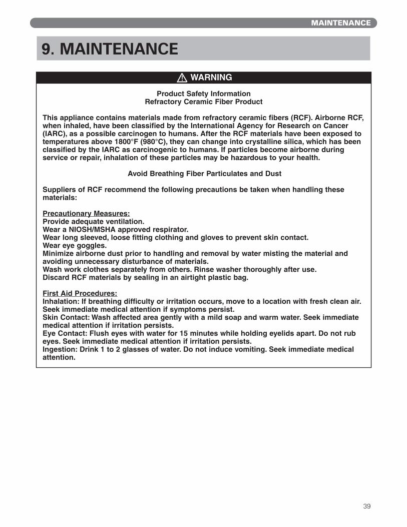
39
9. MAINTENANCE
MAINTENANCE
WARNING
Product Safety InformationRefractory Ceramic Fiber Product
This appliance contains materials made from refractory ceramic fibers (RCF). Airborne RCF,when inhaled, have been classified by the International Agency for Research on Cancer(IARC), as a possible carcinogen to humans. After the RCF materials have been exposed totemperatures above 1800°F (980°C), they can change into crystalline silica, which has beenclassified by the IARC as carcinogenic to humans. If particles become airborne during service or repair, inhalation of these particles may be hazardous to your health.
Avoid Breathing Fiber Particulates and Dust
Suppliers of RCF recommend the following precautions be taken when handling these materials:
Precautionary Measures:Provide adequate ventilation.Wear a NIOSH/MSHA approved respirator.Wear long sleeved, loose fitting clothing and gloves to prevent skin contact.Wear eye goggles.Minimize airborne dust prior to handling and removal by water misting the material andavoiding unnecessary disturbance of materials. Wash work clothes separately from others. Rinse washer thoroughly after use.Discard RCF materials by sealing in an airtight plastic bag.
First Aid Procedures:Inhalation: If breathing difficulty or irritation occurs, move to a location with fresh clean air.Seek immediate medical attention if symptoms persist.Skin Contact: Wash affected area gently with a mild soap and warm water. Seek immediatemedical attention if irritation persists.Eye Contact: Flush eyes with water for 15 minutes while holding eyelids apart. Do not rubeyes. Seek immediate medical attention if irritation persists.Ingestion: Drink 1 to 2 glasses of water. Do not induce vomiting. Seek immediate medicalattention.
40
MAINTENANCE
A. GENERAL (WITH BOILER IN USE)General boiler observation can be performed by theowner. If any potential problems are found, a qualifiedinstaller or service technician/agency must be notified.
1. Remove any combustible materials, gasoline andother flammable liquids and substances that generateflammable vapors from the area where the boiler iscontained.
2. Observe general boiler conditions (unusual noises,vibrations, etc.)
3. Observe operating temperature and pressure on thecombination gauge located in the supply piping onthe left side of the boiler. Boiler pressure shouldnever be higher than 5 psi below the rating shownon the safety relief valve (25 psig maximum for a 30psig rating). Boiler temperature should never behigher than 240° F.
4. Check for water leaks in boiler and system piping.
5. Smell around the appliance area for gas. If you smellgas, follow the procedure listed in the LightingOperating Instructions to shut down appliance inSection 7, Start-Up Procedure Part B.
B. WEEKLY (WITH BOILER IN USE)
1. Flush float-type low-water cut-off (if used) to removesediment from the float bowl as stated in themanufacturer’s instructions.
C. ANNUALLY (BEFORE START OFHEATING SEASON)
1. Check boiler room floor drains for properfunctioning.
2. Check function of the safety relief valve byperforming the following test:a. Check valve piping to determine that it is
properly installed and supported.
b. Check boiler operating temperature and pressure.
c. Lift the try lever on the safety relief valve to thefull open position and hold it for at least fiveseconds or until clean water is discharged.
d. Release the try lever and allow the valve to close.If the valve leaks, operate the lever two or threetimes to clear the valve seat of foreign matter. Itmay take some time to determine if the valve hasshut completely.
e. If the valve continues to leak, it must be replacedbefore the boiler is returned to operation.
f. Check that operating pressure and temperaturehave returned to normal.
g. Check again to confirm that valve has closedcompletely and is not leaking.
3. Test low-water cut-off (if used) as described by themanufacturer.
4. Test limit as described in Section 7, Part C, “Check-Out Procedure”.
5. Test function of ignition system safety shut-offfeatures as described in Section 7, Part C, “Check-Out Procedure”.
6. Remove the top/front jacket panel and inspect forany foreign debris that may have entered through airintake vent.
7. Inspect burner for deterioration. Replace if necessary.
8. With boiler in operation check that condensate isdripping from condensate tubing. Check for anyrestriction in condensate drain line.
D. CONDENSATE CLEANINGINSTRUCTIONS
1. Turn the thermostat down or off so the Pinnacle willnot cycle and then follow the steps below.a. Close manual gas shutoff valve.
b. Disconnect the condensate tubing from theoutside connection (not from the Pinnacle) soflow can be observed.
c. Block the air flow in the exhaust by temporarilyplugging the exhaust from the outside vent.
d. Remove boiler service switch plate. Disconnecttwo gray thermostat wires from thermostat circuitand jump them together. (Refer to Control WiringSchematic, Figure 6.1.) This will cause the fan torun at 100% which will then blow out anysediment that has accumulated in the condensateline. (This process should only take a fewminutes.)
e. The unit should now be ready to re-start.
The following annual inspection must be performedby a qualified service technician.
CAUTION
When servicing or replacing components, beabsolutely certain that the following conditions aremet:
• Water, gas and electricity are off.
• The boiler is at room temperature.
• There is no pressure in the boiler.
DANGER
41
MAINTENANCE
2. Before re-starting the Pinnacle follow the stepsbelow:a. Reconnect the gray wires and unblock the vent.
(IMPORTANT: MAKE SURE EXHAUSTVENT IS NO LONGER BLOCKED!)
b. Open the manual gas shutoff valve and reset thethermostats.
c. Observe the boiler function to make sure you seea condensate flow.
d. If you do not observe a condensate flow, repeatthe above procedure.
3. If the problem is not corrected at this point, it ispossible that there is a material deposit problem.Follow the Coil Cleaning Instructions (Subsection 9E)below to dissolve deposits and clean the heatexchanger.
E. COMBUSTION CHAMBER COILCLEANING INSTRUCTIONS
Before beginning this procedure, you must have onhand the following items:
– a nylon or brass brush (not steel)
– "Rydlyme" (recommended for best results)(available online www.rydlyme.com) or "CLR"(available at most hardware stores)
1. Shut the boiler down and access the heat exchangerusing the following steps:a. Close the manual gas shutoff valve and wait for
the unit to be cool to the touch.
b. Disconnect the condensate piping from the outsideconnections (not from the Pinnacle side) so theflow can be observed.
c. Remove four screws on the 1/2" NPT connectorat the gas valve intake and disconnect the gasvalve electrical connector.
d. Remove the six 10 mm nuts from the burnerplate assembly. Disconnect wire leads to thespark igniter and flame sensor. Disconnect twoMolex plugs from blower motor.
e. Pull the entire burner plate towards you to accessthe heat exchanger coils.
2. Using a spray bottle filled with the recommendedproduct "Rydlyme" or "CLR", spray liberally on thecoils, making sure the solution penetrates and funnelsdown through the condensate hose. If the condensatehose is blocked, let the chemical penetrate for at least15 minutes or until it drains.
3. Use the nylon or brass brush (do not use steel) andscrub coils to remove any buildup, then vacuum thedebris from the coils.
4. Spray coils with clear water, making sure to confinethe spray to the area being cleaned (try to avoidwetting the back ceramic wall of the unit). Flush thecombustion chamber with fresh water. At this point,the Pinnacle should be ready to power back up.
5. Reinstall the burner plate assembly using thefollowing steps:a. Inspect the inside of the heat exchanger for dirt
and debris.
b. Install the burner plate assembly and replace thesix 10 mm nuts.
c. Reconnect the wire leads to the spark igniter,flame sensor and gas valve. (Be sure that thespark igniter is connected to the lead with thelarge insulated connection boot.) Reconnect twoMolex plugs on blower motor.
d. Replace the four screws for the 1/2" NPTconnector on the gas valve. Turn the gas supplyon. (IMPORTANT: CHECK FOR GASLEAKS USING A SOAP SOLUTION.)
e. Reset thermostats. (IMPORTANT: BE SURETHAT THE VENT CONNECTION IS NOTBLOCKED.)
f. Turn the power to the Pinnacle on. Observe thedisplay module to assure proper operation.
g. Initiate a call for heat** and observe thecondensate flow.
h. Reconnect the condensate piping to the drainconnection.
**NOTE: When firing the boiler the first fewtimes you may experience some fluttering ofthe gas burner that may result in a flamelockout. This is normal and will require youto recycle the unit until this clears up. This iscaused by water still present in thecombustion chamber.
6. Inspect exhaust vent and air intake vents for propersupport and joint integrity. Repair as necessary. Referto Section 5, VENTING.
7. Inspect exhaust vent and air intake vent terminationsfor obstructions.
It is extremely important to make sure the exhaustvent is not longer blocked. Failure to do so mayresult in personal injury or death.
DANGER
It is extremely important that you check for leakswhen reconnecting the gas valve and make sure theexhaust vent is no longer blocked. Failure to do somay result in severe personal injury or death.
DANGER
Leaks in the vent system will cause products ofcombustion to enter structure (vent system operatesunder positive pressure).
WARNING
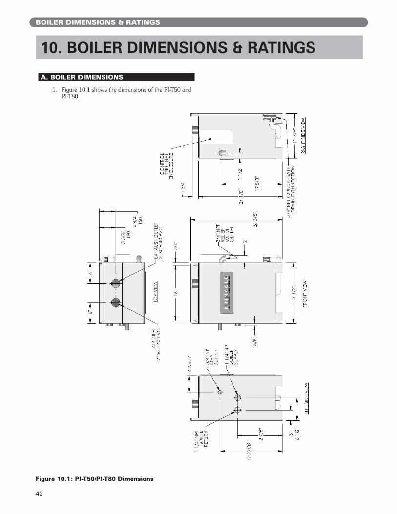
42
A. BOILER DIMENSIONS
1. Figure 10.1 shows the dimensions of the PI-T50 andPI-T80.
10. BOILER DIMENSIONS & RATINGS
BOILER DIMENSIONS & RATINGS
Figure 10.1: PI-T50/PI-T80 Dimensions

43
2. Figure 10.2 shows the dimensions of the PI-80, PI-140 and PI-199.
BOILER DIMENSIONS & RATINGS
Figure 10.2: PI-80/PI-140/PI-199 Dimensions
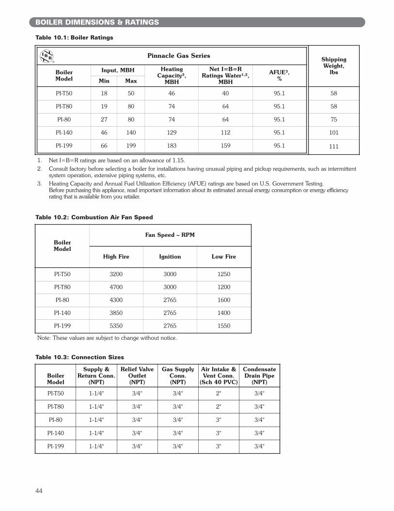
44
BoilerModel
Fan Speed – RPM
High Fire Ignition Low Fire
PI-T50 3200 3000 1250
PI-T80 4700 3000 1200
PI-80 4300 2765 1600
PI-140 3850 2765 1400
PI-199 5350 2765 1550
Table 10.1: Boiler Ratings
Table 10.2: Combustion Air Fan Speed
1. Net I=B=R ratings are based on an allowance of 1.15.2. Consult factory before selecting a boiler for installations having unusual piping and pickup requirements, such as intermittent
system operation, extensive piping systems, etc.3. Heating Capacity and Annual Fuel Utilization Efficiency (AFUE) ratings are based on U.S. Government Testing.
Before purchasing this appliance, read important information about its estimated annual energy consumption or energy efficiencyrating that is available from you retailer.
Note: These values are subject to change without notice.
BOILER DIMENSIONS & RATINGS
BoilerModel
Supply &Return Conn.
(NPT)
Relief ValveOutlet(NPT)
Gas SupplyConn.(NPT)
Air Intake &Vent Conn.
(Sch 40 PVC)
CondensateDrain Pipe
(NPT)
PI-T50 1-1/4" 3/4" 3/4" 2" 3/4"
PI-T80 1-1/4" 3/4" 3/4" 2" 3/4"
PI-80 1-1/4" 3/4" 3/4" 3" 3/4"
PI-140 1-1/4" 3/4" 3/4" 3" 3/4"
PI-199 1-1/4" 3/4" 3/4" 3" 3/4"
Table 10.3: Connection Sizes
Pinnacle Gas Series
BoilerModel
Input, MBH HeatingCapacity³,
MBH
Net I=B=RRatings Water¹,²,
MBH
AFUE³,%Min Max
PI-T50 18 50 46 40 95.1
PI-T80 19 80 74 64 95.1
PI-80 27 80 74 64 95.1
PI-140 46 140 129 112 95.1
PI-199 66 199 183 159 95.1
Shipping Weight,
lbs
58
58
75
101
111

45
This page intentionally left blank.
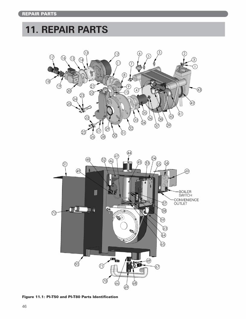
46
REPAIR PARTS
11. REPAIR PARTS
Figure 11.1: PI-T50 and PI-T80 Parts Identification
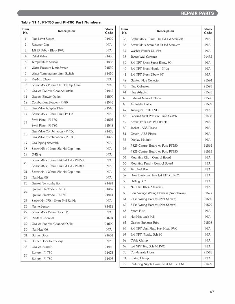
47
ItemNo. Description Stock
Code
1 Flue Limit Switch 91429
2 Retainer Clip N/A
3 1/8 ID Tube - Black PVC N/A
4 Relief Valve 91430
5 Temperature Sensor 91435
6 Water Pressure Limit Switch 91530
7 Water Temperature Limit Switch 91410
8 Pre-Mix Elbow N/A
9 Screw M5 x 25mm Skt Hd Cap 4mm N/A
10 Gasket, Pre-Mix Channel Intake 91442
11 Gasket, Blower Outlet 91500
12 Combustion Blower - PI-80 91546
13 Gas Valve Adapter Plate 91545
14 Screw M5 x 12mm Phil Flat Hd N/A
15Swirl Plate - PI-T50 91592
Swirl Plate - PI-T80 91542
16Gas Valve Combination - PI-T50 91478
Gas Valve Combination - PI-T80 91479
17 Gas Piping Assembly N/A
18 Screw M5 x 12mm Skt Hd Cap 4mm N/A
19 O-Ring N/A
20Screw M4 x 18mm Phil Rd Hd - PI-T50 N/A
Screw M4 x 19mm Phil Rd Hd - PI-T80 N/A
21 Screw M4 x 20mm Skt Hd Cap 4mm N/A
22 Nut Hex M5 N/A
23 Gasket, Sensor/Ignitor 91491
24Ignition Electrode - PI-T50 91467
Ignition Electrode - PI-T80 91411
25 Screw M4-070 x 8mm Phil Rd Hd N/A
26 Flame Sensor 91412
27 Screw M5 x 22mm Torx T25 N/A
28 Pre-Mix Channel 91604
29 Gasket, Pre-Mix Channel Outlet 91600
30 Nut Hex M6 N/A
31 Burner Door 91601
32 Burner Door Refractory N/A
33 Gasket, Burner 91440
34Burner - PI-T50 91472
Burner - PI-T80 91407
ItemNo. Description Stock
Code
35 Screw M6 x 10mm Phil Rd Hd Stainless N/A
36 Screw M4 x 8mm Skt Flt Hd Stainless N/A
37 Washer Fender M4 Flat N/A
38 Target Wall Ceramic 91432
39 3/4 NPT Brass Street Elbow 90° N/A
40 3/4 NPT Brass Nipple - 3" Lg N/A
41 3/4 NPT Brass Elbow 90° N/A
42 Gasket, Flue Collector 91594
43 Flue Collector 91593
44 Flue Adapter 91595
45 Exhaust Manifold Tube 91596
46 Air Intake Baffle 91599
47 Tubing 3/16" ID PVC N/A
48 Blocked Vent Pressure Limit Switch 91498
49 Screw #8 x 1/2" Phil Rd Hd N/A
50 Jacket - ABS Plastic N/A
51 Cover - ABS Plastic N/A
52 Display Module N/A
53P825 Control Board w/ Fuse PI-T50 91564
P825 Control Board w/ Fuse PI-T80 91565
54 Mounting Clip - Control Board N/A
55 Mounting Panel - Control Board N/A
56 Terminal Box N/A
57 Hose Barb Stainless 1/4 IDT x 10-32 N/A
58 O-Ring 007 N/A
59 Nut Hex 10-32 Stainless N/A
60 Low Voltage Wiring Harness (Not Shown) 91577
61 9 Pin Wiring Harness (Not Shown) 91580
62 5 Pin Wiring Harness (Not Shown) 91579
63 Spare Fuse N/A
64 Nut Hex Lock M3 N/A
65 Gasket, Exhaust Tube 91598
66 3/4 NPT Vent Plug, Hex Head PVC N/A
67 3/4 NPT Nipple, Sch 80 N/A
68 Cable Clamp N/A
69 3/4 NPT Tee, Sch 40 PVC N/A
70 Condensate Hose 91518
71 Spring Clamp N/A
72 Reducing Nipple Brass 1-1/4 NPT x 1 NPT 91499
Table 11.1: PI-T50 and PI-T80 Part Numbers
REPAIR PARTS
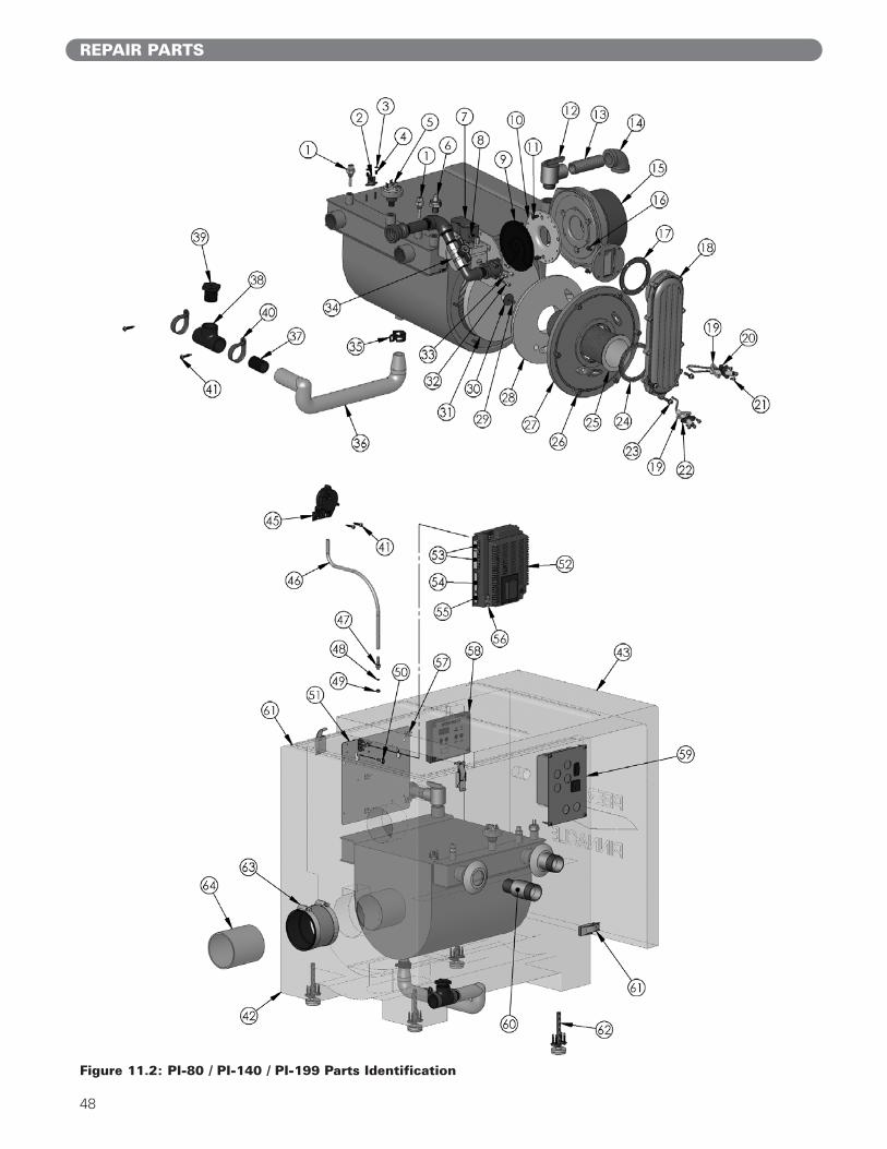
48
REPAIR PARTS
Figure 11.2: PI-80 / PI-140 / PI-199 Parts Identification

49
REPAIR PARTS
ItemNo. Description Stock
Code
1 Temperature Sensor 91532
2 Flue Limit Switch 91429
3 Retainer Clip (Flue Limit) N/A
4 1/8 ID Tube - Black PVC N/A
5 Water Pressure Limit Switch 91609
6 Water Temperature Limit Switch 91410
7
Gas Valve Combination - PI-80 91538
Gas Valve Combination - PI-140 91539
Gas Valve Combination - PI-199 91540
8 Screw M4 x 12mm Phil Rd Hd N/A
9Swirl Plate - PI-80 91542
Swirl Plate - PI-140/PI-199 91543
10 Gas Valve Adapter Plate 91545
11 Screw M5 x 12mm Phil Flat Hd N/A
12 Relief Valve 91430
13 Nipple - 3/4 NPT x 3 N/A
14 Elbow - Brass 3/4 NPT N/A
15
Combustion Blower - PI-80 91546
Combustion Blower - PI-140 91424
Combustion Blower - PI-199 91425
16 Screw M5 x 14mm Skt Hd Cap 4mm N/A
17 Gasket - Blower Outlet 91547
18Premix Channel - PI-80 91548
Premix Channel - PI-140/PI-199 91549
19 Gasket - Flame Sensor / Ignitor 91491
20 Electrode Spark 91550
21 Screw M4-070 x 8mm Phil Rd Hd N/A
22 Flame Sensor 91551
23 Screw M5 x 22mm Torx T25 N/A
24 Gasket - Burner Intake 91552
25
Burner Element - PI-80 91553
Burner Element - PI-140 91554
Burner Element - PI-199 91555
26 Nut Hex M6 N/A
27 Burner Door 91557
28 Refractory Burner Door 91558
29 Screw M4 x 8mm Flat Skt Hd 2.5mm N/A
ItemNo. Description Stock
Code
30 Washer M4 Flat N/A
31 Target Wall Ceramic 91432
32 Screw M4 x 30mm Skt Hd Cap 4mm N/A
33 Screw M4 x 12mm Skt Hd Cap 4mm N/A
34 Gas Piping Assembly N/A
35 Spring Clamp N/A
36 Condensate Hose 91576
37 Nipple - 3/4 NPT x Close Black PVC N/A
38 Tee - 3/4 NPT Black PVC N/A
39 Vent Plug - 3/4 NPT Black PVC N/A
40 Clamp - Condensate Tee N/A
41 Screw #8 X 1/2" Self Tapping Phil Rd Hd N/A
42 Jacket - ABS Plastic N/A
43 Cover - ABS Plastic N/A
45 Blocked Vent Pressure Limit Switch 91498
46 Tubing 3/16" ID PVC 91508
47 Hose Barb S.S. 1/4 IDT x 10-32 N/A
48 O-Ring 007 N/A
49 Nut Hex 10-32 S.S. N/A
50 Screw 1/4-20 X 3/4" Phil Rd Hd N/A
51 Mounting Panel - Control Board N/A
52
P825 Control Board w/ Fuse - PI-80 91566
P825 Control Board w/ Fuse - PI-140 91567
P825 Control Board w/ Fuse - PI-199 91549
53 Low Voltage Wring Harness (Not Shown) 91577
54 9 Pin Wiring Harness (Not Shown) 91580
55 5 Pin Wiring Harness (Not Shown) 91579
56 Spare Fuse N/A
57 Clips - Control Board N/A
58 Display Module 91461
59 Terminal Box 91603
60 Reducing Nipple Brass 1 1/4 NPT x 1 NPT 91499
61Latch & Gasket Assembly - PI-80 91582
Latch & Gasket Assembly - PI-140 & PI-199 91583
62 Leveling Foot 91561
63 Exhaust Coupling N/A
64 Exhaust Stub - 3" Sch 40 PVC N/A
Table 11.2: PI-80 / PI-140 / PI-199 Part Numbers
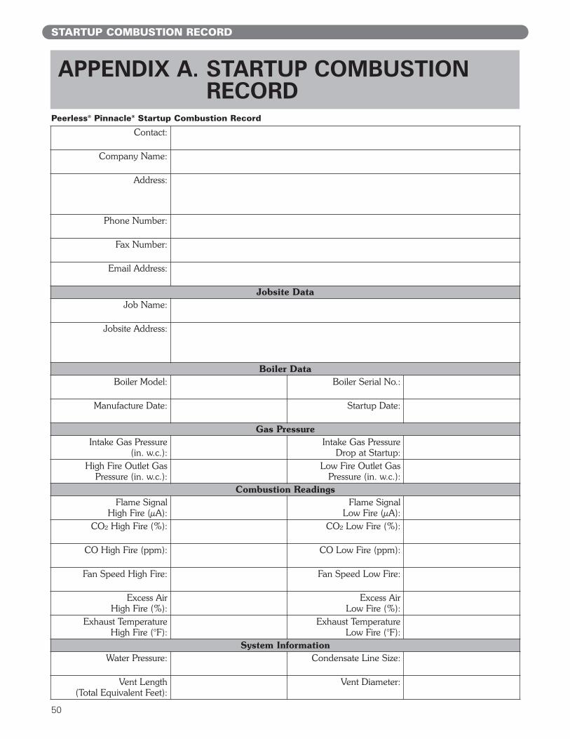
50
STARTUP COMBUSTION RECORD
APPENDIX A. STARTUP COMBUSTIONRECORD
Contact:
Company Name:
Address:
Phone Number:
Fax Number:
Email Address:
Jobsite DataJob Name:
Jobsite Address:
Boiler DataBoiler Model: Boiler Serial No.:
Manufacture Date: Startup Date:
Gas PressureIntake Gas Pressure
(in. w.c.):Intake Gas Pressure
Drop at Startup:High Fire Outlet Gas
Pressure (in. w.c.):Low Fire Outlet Gas
Pressure (in. w.c.):Combustion Readings
Flame Signal High Fire (µA):
Flame SignalLow Fire (µA):
CO² High Fire (%): CO² Low Fire (%):
CO High Fire (ppm): CO Low Fire (ppm):
Fan Speed High Fire: Fan Speed Low Fire:
Excess Air High Fire (%):
Excess Air Low Fire (%):
Exhaust Temperature High Fire (°F):
Exhaust Temperature Low Fire (°F):
System InformationWater Pressure: Condensate Line Size:
Vent Length(Total Equivalent Feet):
Vent Diameter:
Peerless® Pinnacle® Startup Combustion Record

51
NOTES

52
NOTES

Pinnacle®
Gas Boilers Rev2
Peerless®
Stainless Steel
Installation,Operation &MaintenanceManualTO THE INSTALLER:
This manual is the property of the owner and mustbe affixed near the boiler for future reference.
TO THE OWNER:This boiler should be inspected annually by aQualified Service Agency.
PI8127 R2 (10/09-1M) Printed in U.S.A.©2009
PB HEAT, LLC131 S. CHURCH STREET • BALLY, PA 19503
PeerlessBoilers.com
MH27745
CONTROLS
ASME