plain bearings - symbols - applications dit document … 7904-2: 1995(e) foreword iso (the...
TRANSCRIPT
INTERNATIONAL STANDARD
ISO 7904-2
First edition 1995-01-15
Plain bearings - Symbols -
Part 2: Applications
Paket-s lisses - Symboles -
Partie 2: Applica tions
Reference number ISO 790421995(E)
Voorbeeld
Preview
Dit document is een voorbeeld van NEN / This document is a preview by NEN
Dit
do
cum
ent
mag
sle
chts
op
een
sta
nd
-alo
ne
PC
wo
rden
gei
nst
alle
erd
. Geb
ruik
op
een
net
wer
k is
alle
en.
toes
taan
als
een
aan
vulle
nd
e lic
enti
eove
reen
kom
st v
oo
r n
etw
erkg
ebru
ik m
et N
EN
is a
fges
lote
n.
Th
is d
ocu
men
t m
ay o
nly
be
use
d o
n a
sta
nd
-alo
ne
PC
. Use
in a
net
wo
rk is
on
ly p
erm
itte
d w
hen
a su
pp
lem
enta
ry li
cen
se a
gre
emen
t fo
r u
s in
a n
etw
ork
wit
h N
EN
has
bee
n c
on
clu
ded
.
ISO 7904-2: 1995(E)
Foreword
ISO (the International Organization for Standardization) is a worldwide federation of national Standards bodies (ISO member bodies). The work of preparing International Standards is normally carried out through ISO technical committees. Esch member body interested in a subject for which a technical committee has been established has the right to be re- presented on that committee. International organizations, governmental and non-governmental, in liaison with ISO, also take part in the work. ISO collaborates closely with the International Electrotechnical Commission (IEC) on all matters of electrotechnical standardization.
Draft International Standards adopted by the technical committees are circulated to the member bodies for voting. Publication as an International Standard requires approval by at least 75 % of the member bodies casting a vote.
International Standard ISO 7904-2 was prepared by Technical Committee lSO/TC 123, Plain bearings.
ISO 7904 consists of the following Parts, under the general title Plain bearings - Symbols:
- Part 1: Basic Symbols
- Part 2: Applications
0 ISO 1995 All rights reserved. Unless otherwise specified, no part of this publication may be reproduced or utilized in any form or by any means, electronie or mechanical, microfilm, without permissi on in writing from the publisher.
International Organization for Standardization Case Postale 56 l CH-121 1 Geneve 20 l Switze
tncluding photocopyrng and
rland Printed in Switzerland
ii
Voorbeeld
Preview
Dit document is een voorbeeld van NEN / This document is a preview by NEN
INTERNATIONAL STANDARD 0 ISO ISO 7904-2: 1995(E)
Plain bearings - Symbols -
Part 2: Applications
1 Scope
This part of ISO 7904 specifies practical applications of the general Symbols laid down in ISO 7904-1 with regard to the calculations, design and testing of plain bearings.
ISO 7904-1 distinguishes between basic characters and additional signs. Additional signs are subscripts and superscripts. The Symbols necessary for plain bearing calculations, design, manufacture and testing are combinations of the above-mentioned signs.
The Symbols which have been found necessary for the calculations, design and testing of plain bearings are given in 3.1 and 3.2. They have been combined according to the recommendations given in ISO 7904-1. The list may be enlarged, if necessary.
Angles and directions of rotation are defined positively as rotating left-hand (counter-clockwise); the same applies to rotational frequencies, peripheral and angu- lar velocities.
2 Normative reference
The following Standard contains provisions which, through reference in this text, constitute provisions of this part of ISO 7904. At the time of publication, the edition indicated was valid. All Standards are subject to revision, and Parties to agreements based on this part of ISO 7904 are encouraged to investigate the possibility of applying the most recent edition of the Standard indicated below. Members of IEC and ISO
maintain registers of currently valid International Standards.
ISO 7904-1 :1994, Plain bearings - Symbols - Part 7: Basic symbols.
3 Symbols and terms
31 .
A
A lan
A* lan
AP
AS
a
UF
a;
ah4
B
B*
Symbols (Roman alphabet)
heat-emitting surface (bearing housing); elongation at fracture
land area
relative land area
oil pocket area
area of Cross-section
distance; acceleration; thermal diffusivity
distance between entrance of the gap and the location of the Pivot Point
relative distance between entrance of the gap and the location of the Pivot Point
off-set of bearing support
(breadth); nominal bearing width; effective bearing width at right angles to the direction of motion; diameter of a circular tilting pad
relative width; width ratio
Voorbeeld
Preview
Dit document is een voorbeeld van NEN / This document is a preview by NEN
ISO 7904-2: 1995(E) 0 ISO
BH
B tot
b ax
bc
bG
bP
C
c’
CD
c,
C D,eff
C D,max
C D,min
C man
C max
C min
CR
G
C R,eff
C R,max
C R,min
C wed
c
cJ
cP
external width of bearing housing in axial di- rection
total bearing width at right angles to the di- rection of motion
width of axial outlet
width of circumferential outlet
width of oil groove; width of bleed groove
width of oil pocket
nominal clearance; concentration; chamfer
relative bearing clearance (also $)
differente between lobe or pad bore radius and shaft radius of a multi-lobed and tilting pad journal bearing
bearing clearance; bearing diametral clear- ante (differente between journal bearing bore and shaft diameter)
mean value of CD
effective bearing diametral clearance
maximum value of CD
minimum value of CD
clearance range due to machining tolerantes of a multi-lobed journal bearing
maximum clearance of multi-lobed bearing
minimum clearance of multi-lobed bearing
bearing radial clearance (differente between journal bearing radius and shaft radius)
mean value of CR
effective bearing radial clearance
maximum value of CR
minimum value of CR
wedge depth of a multi-taper land bearing (“thrust bearing clearance”)
specific heat capacity; stiffness coefficient
flexural stiffness of shaft
specific heat capacity (with p constant)
D
DB
D B,max
D B,min
DH
Di
DJ
D J,max
D J,min
DO
d
d CP
dL
E
E’
EB
EJ
E El
e
e*
F
F*
F;
F E,tr
nominal bearing diameter (inside diameter of journal bearing; mean diameter of thrust- bearing carrier ring)
twice the radius of lobe or pad in a multi- lobed and tilting pad journal bearing
maximum value of DB
minimum value of DB
diameter of bearing housing
inside diameter of thrust-bearing carrier ring
shaft diameter
maximum value of DJ
minimum value of DJ
outside diameter of thrust-bearing carrier ring
diameter; damping coefficient
diameter of capillaries
oil hole diameter
modulus of elasticity
Parameter of elasticity
modulus of elasticity of bearing material
modulus of elasticity of rotor material (sliding surface)
resultant modulus of elasticity
eccentricity (eccentricity between the axis of the shaft and the bearing axis)
relative eccentricity (also E)
eccentricity of sliding surfaces (Segments) of a multi-lobed and tilting pad journal bearing
eccentricity of shaft in direction of load of a multi-lobed journal bearing
bearing forte (nominal load)
bearing forte Parameter
bearing forte (with EHD influence)
bearing forte Parameter (with EHD influence)
bearing forte (with EHD influence) at the limit of boundary lubrication
Voorbeeld
Preview
Dit document is een voorbeeld van NEN / This document is a preview by NEN
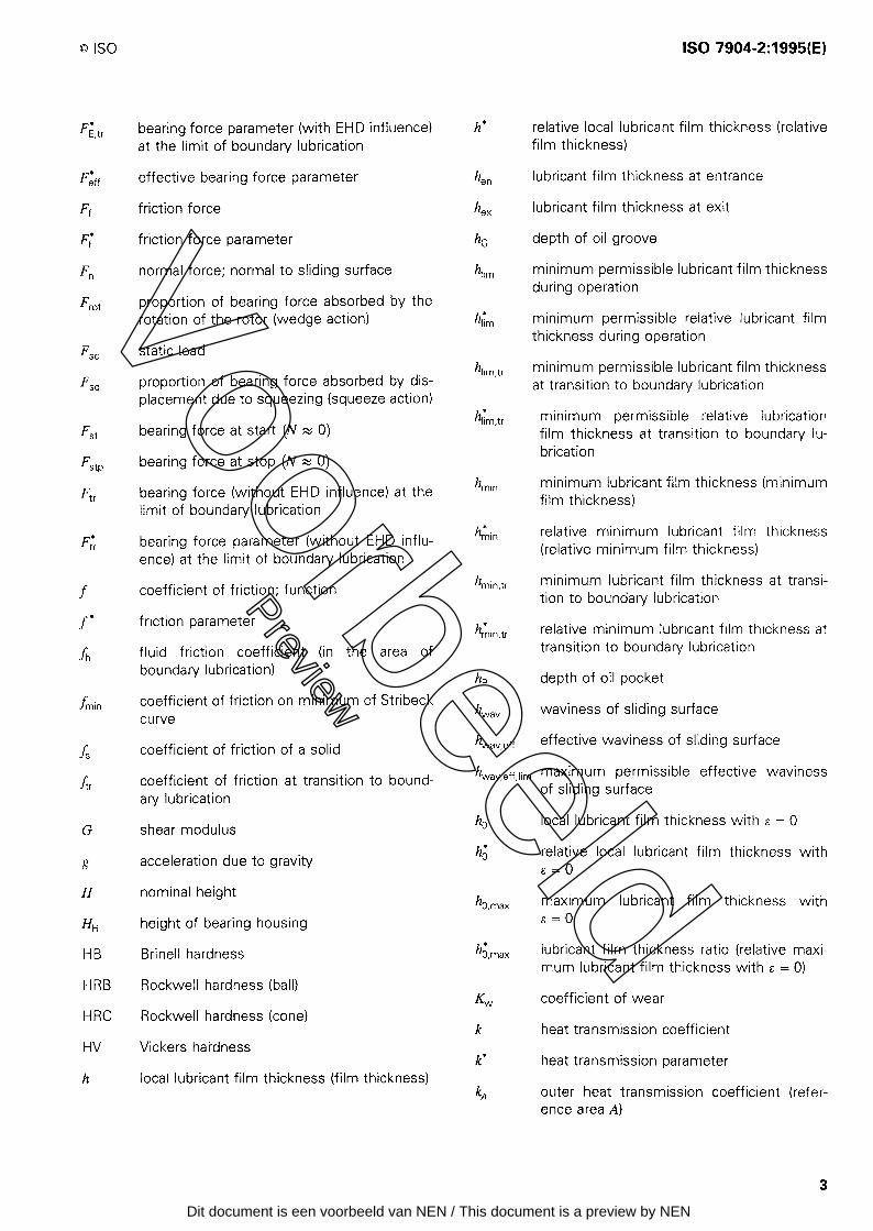
0 ISO ISO 7904-2: 1995(E)
h* relat ive local lubr film thickness)
icant film thickness (relative F’ E,tr bearing forte Parameter (with EHD influence) at the limit of boundary lubrication
h en Iubricant film thickness at entrance F’ eff
Ff
F;
Fn
F rot
effective bearing forte Parameter
h ex lubricant film thickness at exit f riction forte
hG depth of oil groove friction forte Parameter
normal forte; normal to sliding surface 4 im minimum permissible Iubricant film thickness during Operation
Proportion of bearing forte absorbed by the rotation of the rotor (wedge action) 4 *
im minimum permissible relative Iubricant film thickness during Operation
F sc
F w
static load 4 im,tr minimum permissible Iubricant film thickness
at transition to boundary lubrication Proportion of bearing forte absorbed by dis- placement due to squeezing (squeeze action)
4 l im,tr minimum permissible relative lubrication film thickness at transition to boundary lu- brication
bearing forte at Start (IV N 0) Fst
F QP
Ftr
bearing forte at stop (N N 0) h min minimum lubricant film thickness (minimum
film thickness) bearing forte (without EHD influence) at the limit of boundary lubrication
h* 1 min relative minimum Iubricant film thickness (relative minimum film thickness) bearing forte Parameter (without EHD influ-
ence) at the limit of boundary lubrication h min,tr minimum Iubricant film thickness at transi-
tion to boundary lubrication coefficient of friction; function f
f *
fh
friction Parameter h* min,tr relative minimum lubricant film thickness at transition to boundary lubrication fluid friction coefficient (in the area of
boundary lubrication)
coefficient of friction on minimum of Stribeck curve
depth of oil pocket
f min kV av waviness of sliding surface
hw av, eff effective waviness of sliding surface coefficient of friction of a solid f S
f tr kV av,eff,lim maximum permissible effective waviness of sliding surface
coefficient of friction at transition to bound- ary lubrication
h0 local lubricant film thickness with E = 0 shear modulus G * h, relative local lubricant film thickness with
E 0 = acceleration due to gravity g
H nominal height ho ,max maximum lubricant film thickness with
E 0 = height of bearing housing Hl-l h’ 0,max lubricant film thickness ratio (relative maxi-
mum Iubricant film thickness with E = 0) HB
HRB
HRC
HV
h
Brinell hardness
Rockwell hardness (ball) coefficient of wear
Rockwell hardness (cone) k heat transmission coefficient
Vickers hardness k * heat transmission Parameter
local Iubricant film thickness (film thickness) kA outer heat transmission coefficient (refer-
ence area A)
Voorbeeld
Preview
Dit document is een voorbeeld van NEN / This document is a preview by NEN
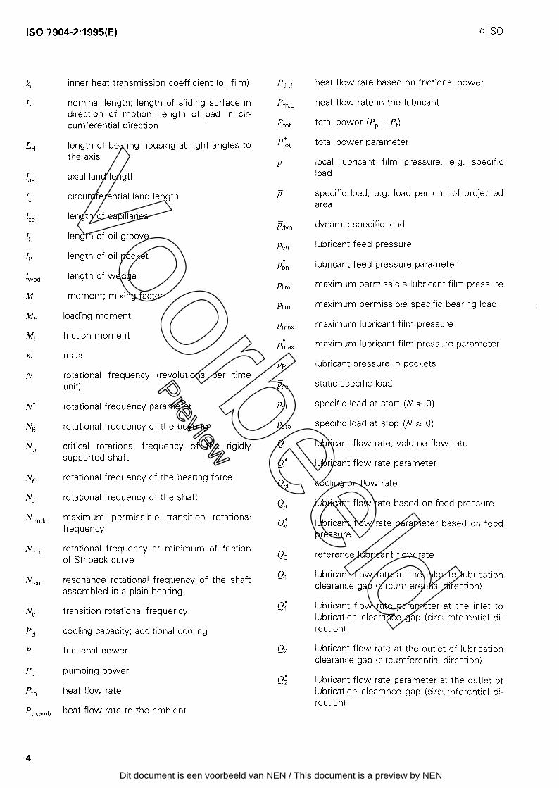
ISO 7904-2: 1995(E) 0 ISO
4 L
Lli
1 ax
4
I CP
1,
2,
1 wed
M
m
N
N’
NB
Ncr
NF
NJ
Nlim tr I
n4nin
N rsn
Ntr
Pc1
Pf
pP
‘th
P. . 1 th,amb
inner heat transmission coefficient (Oil film)
nominal length; length of sliding surface in direction of motion; length of pad in cir- cumferential direction
length of bearing housing at right angles to the axis
axial land length
circumferential land length
length of capillaries
length of oil groove
length of oil pocket
length of wedge
moment; mixing factor
loading moment
friction moment
mass
rotational frequency (revolutions per time unit)
rotational frequency Parameter
rotational frequency of the bearing
critical rotational frequency of the rigidly supported shaft
rotational frequency of the bearing forte
rotational frequency of the shaft
maximum permissible transition rotational frequency
rotational frequency at minimum of friction of Stribeck curve
resonance rotational frequency of the shaft assembled in a plain bearing
transition rotational frequency
cooling capacity; additional cooling
frictional power
pumping power
heat flow rate
heat flow rate to the ambient
P th,f
P th,L
P tot P* tot
P
P
- Pdyn
P en
P* en
Plim
Rm
Pmax
P* max
PP - Pst - Pst - Pstp
Q
Q *
Q Cl
Q P
Q * P
Qo Q 1
Q ;
Q2
Q;
heat flow rate based on frictional power
heat flow rate in the Iubricant
total power (Pp + Pf)
total power Parameter
local Iubricant film pressure, e.g. specific load
specific load, e.g. load per unit of projected area
dynamic specific load
Iubricant feed pressure
lubricant feed pressure Parameter
maximum permissible Iubricant film pressure
maximum permissible specific bearing Ioad
maximum lubricant film pressure
maximum lubricant film pressure Parameter
Iubricant pressure in pockets
static specific load
specific load at Start (N z 0)
specific load at stop (N h: 0)
lubricant flow rate; volume flow rate
lubricant flow rate Parameter
cooling oil flow rate
lubricant flow rate based on feed pressure
lubricant flow rate Parameter based on feed pressure
reference lubricant flow rate
lubricant flow rate at the inlet to lubrication clearance gap (circumferential direction)
lubricant flow rate Parameter at the inlet to lubrication clearance gap (circumferential di- rection)
lubricant flow rate at the outlet of lubrication clearance gap (circumferential direction)
lubricant flow rate Parameter at the outlet of lubrication clearance gap (circumferential di- rection)
Voorbeeld
Preview
Dit document is een voorbeeld van NEN / This document is a preview by NEN
NEN Standards Products & Servicest.a.v. afdeling KlantenserviceAntwoordnummer 102142600 WB Delft
Wilt u deze norm in PDF-formaat? Deze bestelt u eenvoudig via www.nen.nl/normshop
Gratis e-mailnieuwsbrievenWilt u op de hoogte blijven van de laatste ontwikkelingen op het gebied van normen,
normalisatie en regelgeving? Neem dan een gratis abonnement op een van onze
e-mailnieuwsbrieven. www.nen.nl/nieuwsbrieven
Gegevens Bedrijf / Instelling
T.a.v. O M O V
Klantnummer NEN
Uw ordernummer BTW nummer
Postbus / Adres
Postcode Plaats
Telefoon Fax
Factuuradres (indien dit afwijkt van bovenstaand adres)
Postbus / Adres
Postcode Plaats
Datum Handtekening
NEN Standards Products & Services
Postbus 50592600 GB Delft
Vlinderweg 62623 AX Delft
T (015) 2 690 390F (015) 2 690 271
www.nen.nl/normshop
RetournerenFax: (015) 2 690 271
E-mail: [email protected]
Post: NEN Standards Products
& Services,
t.a.v. afdeling Klantenservice
Antwoordnummer 10214,
2600 WB Delft
(geen postzegel nodig).
Voorwaarden• De prijzen zijn geldig
tot 31 december 2016,
tenzij anders aangegeven.
• Alle prijzen zijn excl. btw,
verzend- en handelingskosten
en onder voorbehoud bij
o.m. ISO- en IEC-normen.
• Bestelt u via de normshop een
pdf, dan betaalt u geen
handeling en verzendkosten.
• Meer informatie: telefoon
(015) 2 690 391, dagelijks
van 8.30 tot 17.00 uur.
• Wijzigingen en typefouten
in teksten en prijsinformatie
voorbehouden.
• U kunt onze algemene
voorwaarden terugvinden op:
www.nen.nl/leveringsvoorwaarden.
preview - 2016
Bestelformulier
Normalisatie: de wereld op één lijn.
Stuur naar:
Ja, ik bestel
€ 31.57__ ex. ISO 7904-2:1995 en Plain bearings - Symbols - Part 2: Applications