plaster system brochure (english) - sa920 - usg. · pdf filetwo-coat veneer plaster systems...
TRANSCRIPT
Fire performance, beauty and
durability for interior residential
and commercial spaces
PlasterSystems SA-920
Plaster systems offer a number of practical and aesthetic advantages over gypsum panels and other interior finishes.
Plaster permits a great deal of design flexibility, combined with fire performance, strength and durability. These factors improve lifecycleeconomy when compared to drywall.
Because plaster systems are truly monolithic, they provide surfaces that minimize or eliminate irregularities associated with standard drywall construction (ridging, boarding, nail pops, etc.).
Beauty and Strength
3 CGC Plaster Systems
User’s Guide
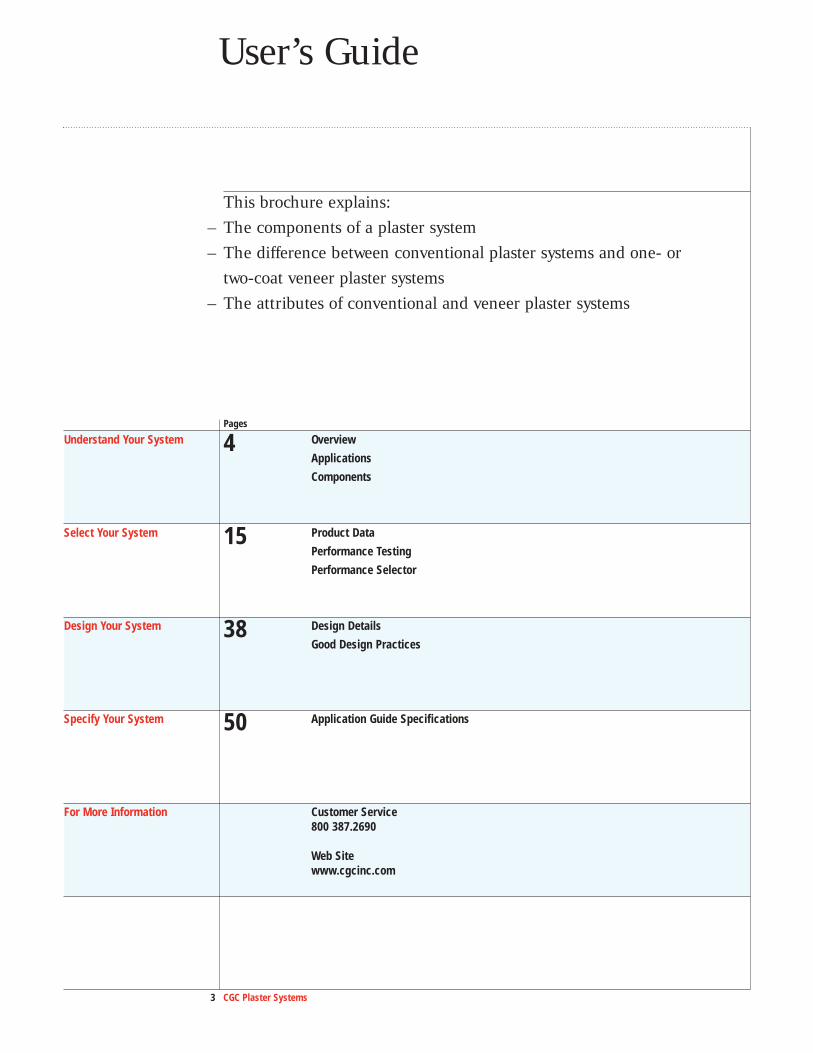
This brochure explains:– The components of a plaster system– The difference between conventional plaster systems and one- or
two-coat veneer plaster systems– The attributes of conventional and veneer plaster systems
Pages
Understand Your System 4 Overview
Applications
Components
Select Your System 15 Product Data
Performance Testing
Performance Selector
Design Your System 38 Design Details
Good Design Practices
Specify Your System 50 Application Guide Specifications
For More Information Customer Service800 387.2690
Web Sitewww.cgcinc.com
Plaster systems provide improved fire and abuse resistance over conventional drywall systems. In addition, they allow for a variety of aesthetic applications and better acoustic performance.
Depending on the application, either conventional or veneer plastersystems can be used. Conventional plaster systems use a thicker plaster coatover a metal lath and provide increased fire and wear resistance, whileone- or two-coat veneer systems are faster and less expensive to apply.
Plaster systems typically consist of a substrate, a basecoat plaster and a finish plaster.
Substrates Substrates can be either metal lath, unit masonry, monolithic concrete, or a recommended gypsum base, cement board
or fibre-reinforced gypsum panel.
Basecoat Plasters Basecoat plasters provide strength and rigidity, compensating for substrate imperfections and resulting in even, straight
walls and ceilings. In conventional plaster systems, basecoat plasters are generally applied 13 to 25 mm (1/2� to 1�)
thick, in one or two separate applications, depending on the substrate. In veneer plaster systems, basecoat plasters are
applied approximately 1.5 mm (1/16�) thick.
Basecoat plasters are supplied in two forms: mill aggregated (which requires only mixing with water), and neat
(which requires the addition of aggregate at the job site).
Finish Plasters In conventional plaster systems, finish plasters are applied to properly prepared gypsum basecoat plasters to form the
wearing surface of walls and ceilings. In veneer finish applications, finish plasters can be applied to any properly prepared
basecoat or directly to a gypsum base. Finishes are approximately 1.5 to 2.4 mm (1/16� to 3/32�) thick, and can be
smooth troweled, floated or textured.
Finish plasters are supplied in two forms: factory-prepared finishes require only the addition of water, while gauging
plasters require the addition of lime putty.
Fire Resistance All ULC and UL assemblies listed in this folder are certified for use in Canada and comply with CAN/ULC S101 for fire resistance.
The Standards Council of Canada recognizes ULC and UL as accredited testing and certification organizations for certification of
materials and systems to Canadian standards.
Loading Conditions All load bearing assemblies, with exception of steel columns, are required to be loaded to their full design capacity during tests for fire resistance
as required in CAN/ULC S101 and ASTM E119. The 2005 edition of the National Building Code of Canada now references the Third Edition of
CAN/ULC S101-04 that requires applied loads be calculated under Limit States design principles. The previous edition referenced in the 1995
National Building Code of Canada permitted the use of Working Stress or Limit States principles for calculation of applied loads. In some cases
there may be a significant difference between these calculations of applied loads. In these cases ULC and UL are amending their on-line and
subsequent printed directories to provide guidance in the “Guide Information” section and notating individual designs that may require
investigation as to “Load Restriction” or “Reduction” of the design. This applies to both ULC and UL designs as well as assemblies
certified by other Standards Council of Canada recognized agencies such as Intertek (Warnock-Hersey International)
4 CGC Plaster Systems
Overview
5 CGC Plaster Systems
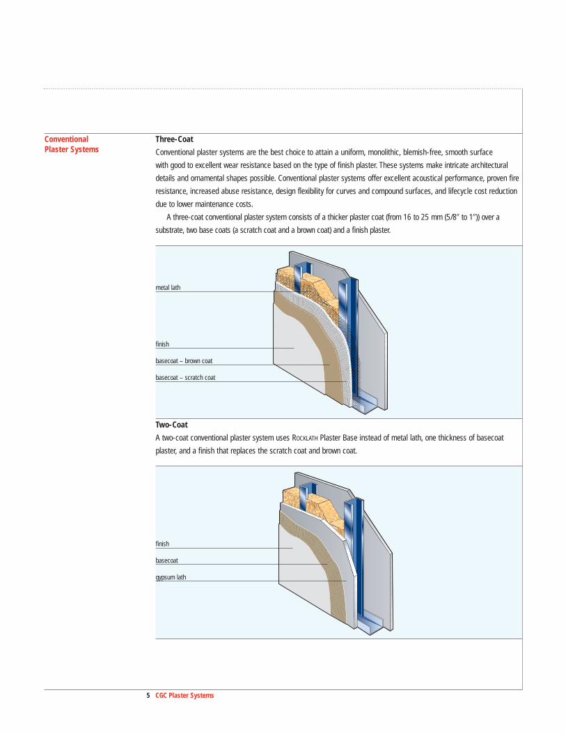
Conventional Three-CoatPlaster Systems Conventional plaster systems are the best choice to attain a uniform, monolithic, blemish-free, smooth surface
with good to excellent wear resistance based on the type of finish plaster. These systems make intricate architectural
details and ornamental shapes possible. Conventional plaster systems offer excellent acoustical performance, proven fire
resistance, increased abuse resistance, design flexibility for curves and compound surfaces, and lifecycle cost reduction
due to lower maintenance costs.
A three-coat conventional plaster system consists of a thicker plaster coat (from 16 to 25 mm (5/8� to 1�)) over a
substrate, two base coats (a scratch coat and a brown coat) and a finish plaster.
Two-Coat
A two-coat conventional plaster system uses ROCKLATH Plaster Base instead of metal lath, one thickness of basecoat
plaster, and a finish that replaces the scratch coat and brown coat.
finish
basecoat – brown coat
basecoat – scratch coat
metal lath
finish
basecoat
gypsum lath
6 CGC Plaster Systems
Overview
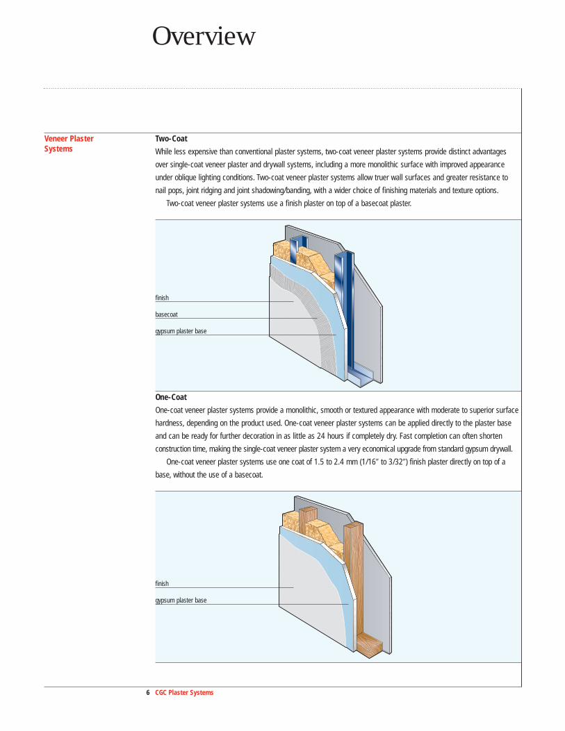
Veneer Plaster Two-CoatSystems While less expensive than conventional plaster systems, two-coat veneer plaster systems provide distinct advantages
over single-coat veneer plaster and drywall systems, including a more monolithic surface with improved appearance
under oblique lighting conditions. Two-coat veneer plaster systems allow truer wall surfaces and greater resistance to
nail pops, joint ridging and joint shadowing/banding, with a wider choice of finishing materials and texture options.
Two-coat veneer plaster systems use a finish plaster on top of a basecoat plaster.
One-Coat
One-coat veneer plaster systems provide a monolithic, smooth or textured appearance with moderate to superior surface
hardness, depending on the product used. One-coat veneer plaster systems can be applied directly to the plaster base
and can be ready for further decoration in as little as 24 hours if completely dry. Fast completion can often shorten
construction time, making the single-coat veneer plaster system a very economical upgrade from standard gypsum drywall.
One-coat veneer plaster systems use one coat of 1.5 to 2.4 mm (1/16� to 3/32�) finish plaster directly on top of a
base, without the use of a basecoat.
finish
basecoat
gypsum plaster base
finish
gypsum plaster base
7 CGC Plaster Systems7 CGC Plaster Systems
Applications
Conventional Conventional plaster systems provide the highest quality finish and the capability to create complex high-end surfaces Plaster Systems such as barrel vaults and domes. In addition, secured storage areas for homes, bank vaults, furriers, jewelers,
correctional facilities, and embassies can be built with STRUCTOCORE™ Security Wall Systems.
Wood Framed
For wood-framed construction, a conventional plaster system provides:
– Fire resistance
– Improved acoustical separation between rooms
Steel Framed
For steel-framed construction, a conventional plaster system provides:
– Fire protection for beams and columns
– Durability and reduced lifecycle costs in high-usage applications
– Improved performance for acoustical applications such as concert halls and theaters
Veneer Wood FramedPlaster Systems For wood-framed construction, a veneer plaster system provides:
– Durability, including abrasion and crack resistance, for high-traffic areas
– 1-hour and 2-hour fire resistance ratings, depending on components used
– Sound control up to 52 STC with the use of resilient channels and sound insulation
– Easy application and fast drying for surfaces that are ready for next-day decorating or painting
Steel Framed
For steel-framed construction, a veneer plaster system provides:
– Fire-resistance ratings up to 4 hours
– Up to 21 MPa (3000 psi) for the ultimate in finish plaster resistance to abrasion, scratching and indentation in high-traffic areas
– Sound isolation up to 62 STC
– Versatility for most dimensions or modules in virtually all buildings, with excellent workability
– Lighter weight than masonry assemblies of the same thickness
– Simple, inexpensive components that can be installed quickly at a lower cost than conventional plaster systems
Special Applications The CGC Drywall Suspension System is a low-cost alternative to cold-rolled channel for framing custom details such as
barrel vaults and domes. It features:
– Pre-fabricated hub and pre-formed curved tees
– Suitable framing system for both conventional and veneer plaster systems
For more information, see AC3152, Drywall Suspension System.
8 CGC Plaster Systems
Components
8 CGC Plaster Systems
Substitutions of any of the components are not recommended or supported by CGC. Refer to the appropriate product material safety data sheet for complete health and safety information.
Substrates
Selector Conventional VeneerMetal Lath •
DUROCK Cement Board (CGC Plaster Bonder) • •
FIBEROCK Interior AQUA-TOUGH Panels (CGC Plaster Bonder) • •
GRAND PRIX Gypsum Base (CGC Plaster Bonder) • •
Monolithic Concrete • •
Unit Masonry • •
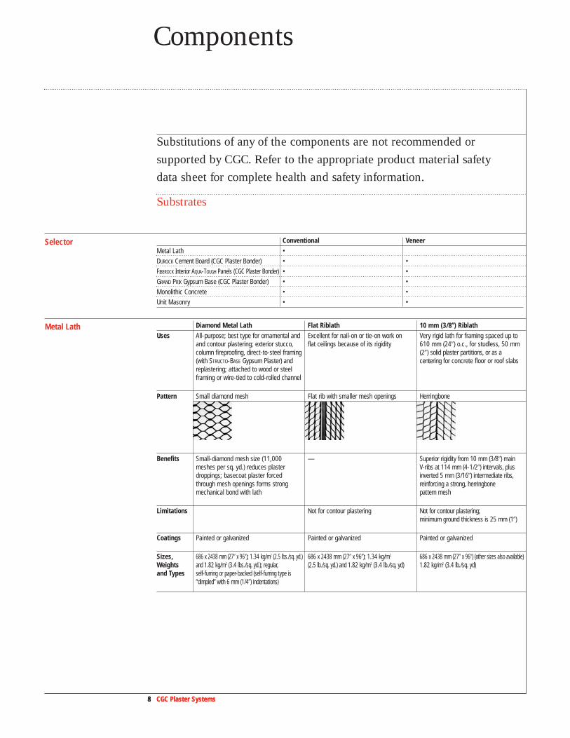
Metal Lath Diamond Metal Lath Flat Riblath 10 mm (3/8��) RiblathUses All-purpose; best type for ornamental and Excellent for nail-on or tie-on work on Very rigid lath for framing spaced up to
and contour plastering; exterior stucco, flat ceilings because of its rigidity 610 mm (24�) o.c., for studless, 50 mm column fireproofing, direct-to-steel framing (2�) solid plaster partitions, or as a (with STRUCTO-BASE Gypsum Plaster) and centering for concrete floor or roof slabsreplastering; attached to wood or steelframing or wire-tied to cold-rolled channel
Pattern Small diamond mesh Flat rib with smaller mesh openings Herringbone
Benefits Small-diamond mesh size (11,000 — Superior rigidity from 10 mm (3/8�) main meshes per sq. yd.) reduces plaster V-ribs at 114 mm (4-1/2�) intervals, plus droppings; basecoat plaster forced inverted 5 mm (3/16�) intermediate ribs,through mesh openings forms strong reinforcing a strong, herringbone mechanical bond with lath pattern mesh
Limitations Not for contour plastering Not for contour plastering;minimum ground thickness is 25 mm (1�)
Coatings Painted or galvanized Painted or galvanized Painted or galvanized
Sizes, 686 x 2438 mm (27� x 96�); 1.34 kg/m2 (2.5 lbs./sq. yd.) 686 x 2438 mm (27� x 96�); 1.34 kg/m2 686 x 2438 mm (27� x 96�) (other sizes also available)Weights and 1.82 kg/m2 (3.4 lbs./sq. yd.); regular, (2.5 lb./sq. yd.) and 1.82 kg/m2 (3.4 lb./sq. yd) 1.82 kg/m2 (3.4 lb./sq. yd) and Types self-furring or paper-backed (self-furring type is
“dimpled” with 6 mm (1/4�) indentations)
9 CGC Plaster Systems
Components
9 CGC Plaster Systems
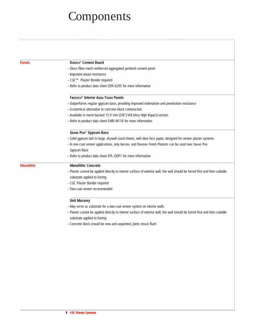
Panels DUROCK® Cement Board
– Glass-fibre-mesh reinforced aggregated portland cement panel
– Improved abuse resistance
– CGC™ Plaster Bonder required
– Refer to product data sheet EDR-6295 for more information
FIBEROCK® Interior AQUA-TOUGH Panels
– Outperforms regular gypsum base, providing improved indentation and penetration resistance
– Economical alternative to concrete block construction
– Available in mesh-backed 15.9 mm (5/8�) VHI (Very High Impact) version
– Refer to product data sheet EWB-W118 for more information
GRAND PRIX® Gypsum Base
– Solid gypsum lath in large, drywall-sized sheets, with blue face paper, designed for veneer plaster systems
– In one-coat veneer applications, only IMPERIAL and DIAMOND Finish Plasters can be used over GRAND PRIX
Gypsum Base
– Refer to product data sheet EPL-OOP1 for more information
Monolithic Monolithic Concrete
– Plaster cannot be applied directly to interior surface of exterior wall; the wall should be furred first and then suitable
substrate applied to furring
– CGC Plaster Bonder required
– Two-coat veneer recommended
Unit Masonry
– May serve as substrate for a two-coat veneer system on interior walls
– Plaster cannot be applied directly to interior surface of exterior wall; the wall should be furred first and then suitable
substrate applied to furring
– Concrete block should be new and unpainted, joints struck flush

10 CGC Plaster Systems10 CGC Plaster Systems
Basecoat Plasters
Selector Conventional VeneerDIAMOND Veneer Basecoat Plaster •
IMPERIAL Basecoat Plaster •
RED TOP Gypsum Plaster •
STRUCTO-LITE Gypsum Plaster •
Basecoat plasters provide strength and rigidity, building the wall to thickness to provide substrate and bond for finish
plaster. They are used to achieve even, straight walls and ceilings, compensating for substrate irregularities. Basecoat
plasters are generally applied in one or two applications of 13 to 25 mm (1/2� to 1�), depending on the substrate.
DIAMOND® Veneer Basecoat Plaster
– Quality walls and ceilings for residential or commercial construction where the superior strength of IMPERIAL® Basecoat
Plaster is not essential
– Superior workability provides ease and speed of application to achieve a high production rate with increased coverage
– Exceptional integral bond with all finish plasters
– Refer to product data sheet EPL-1080 for more information
IMPERIAL Basecoat Plaster
– High-strength veneer basecoat plaster (21 MPa (3,000 psi) compressive strength) for use in two-coat applications
– Can be used with a veneer plaster finish, such as DIAMOND Interior Finish or IMPERIAL Finish Plaster
– Where ease of workability and application are a major concern, use RED TOP® Finish, Gauging Plaster/lime putty
– Refer to product data sheet EPL-1078 for more information
RED TOP Gypsum Plaster
– General purpose basecoat plaster available in different forms to suit regional preferences
– Requires adding aggregate and water on the job
– Refer to product data sheet P752 for more information
11 CGC Plaster Systems
Components
11 CGC Plaster Systems
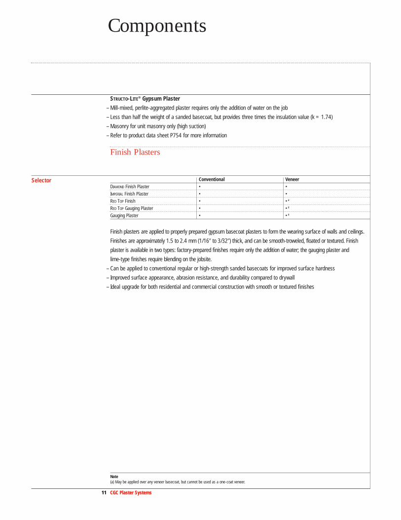
STRUCTO-LITE® Gypsum Plaster
– Mill-mixed, perlite-aggregated plaster requires only the addition of water on the job
– Less than half the weight of a sanded basecoat, but provides three times the insulation value (k = 1.74)
– Masonry for unit masonry only (high suction)
– Refer to product data sheet P754 for more information
Finish Plasters
Selector Conventional VeneerDIAMOND Finish Plaster • •
IMPERIAL Finish Plaster • •
RED TOP Finish • •a
RED TOP Gauging Plaster • •a
Gauging Plaster • •a
Finish plasters are applied to properly prepared gypsum basecoat plasters to form the wearing surface of walls and ceilings.
Finishes are approximately 1.5 to 2.4 mm (1/16� to 3/32�) thick, and can be smooth-troweled, floated or textured. Finish
plaster is available in two types: factory-prepared finishes require only the addition of water; the gauging plaster and
lime-type finishes require blending on the jobsite.
– Can be applied to conventional regular or high-strength sanded basecoats for improved surface hardness
– Improved surface appearance, abrasion resistance, and durability compared to drywall
– Ideal upgrade for both residential and commercial construction with smooth or textured finishes
Note (a) May be applied over any veneer basecoat, but cannot be used as a one-coat veneer.
12 CGC Plaster Systems12 CGC Plaster Systems
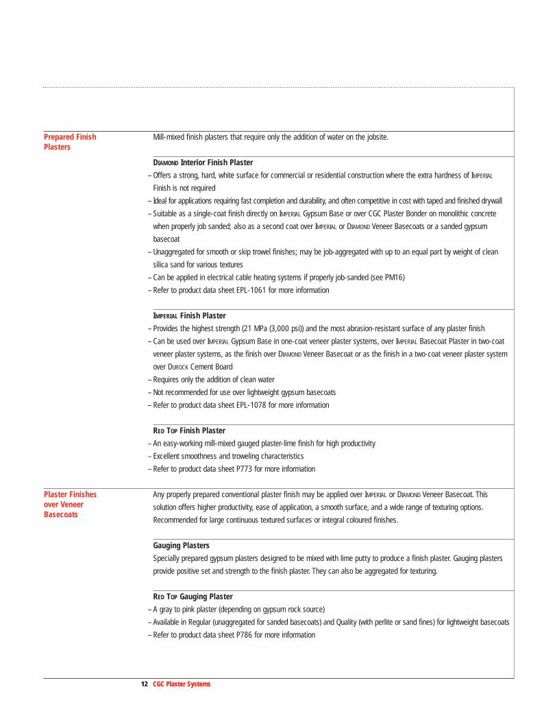
Prepared Finish Mill-mixed finish plasters that require only the addition of water on the jobsite.Plasters
DIAMOND Interior Finish Plaster
– Offers a strong, hard, white surface for commercial or residential construction where the extra hardness of IMPERIAL
Finish is not required
– Ideal for applications requiring fast completion and durability, and often competitive in cost with taped and finished drywall
– Suitable as a single-coat finish directly on IMPERIAL Gypsum Base or over CGC Plaster Bonder on monolithic concrete
when properly job sanded; also as a second coat over IMPERIAL or DIAMOND Veneer Basecoats or a sanded gypsum
basecoat
– Unaggregated for smooth or skip trowel finishes; may be job-aggregated with up to an equal part by weight of clean
silica sand for various textures
– Can be applied in electrical cable heating systems if properly job-sanded (see PM16)
– Refer to product data sheet EPL-1061 for more information
IMPERIAL Finish Plaster
– Provides the highest strength (21 MPa (3,000 psi)) and the most abrasion-resistant surface of any plaster finish
– Can be used over IMPERIAL Gypsum Base in one-coat veneer plaster systems, over IMPERIAL Basecoat Plaster in two-coat
veneer plaster systems, as the finish over DIAMOND Veneer Basecoat or as the finish in a two-coat veneer plaster system
over DUROCK Cement Board
– Requires only the addition of clean water
– Not recommended for use over lightweight gypsum basecoats
– Refer to product data sheet EPL-1078 for more information
RED TOP Finish Plaster
– An easy-working mill-mixed gauged plaster-lime finish for high productivity
– Excellent smoothness and troweling characteristics
– Refer to product data sheet P773 for more information
Plaster Finishes Any properly prepared conventional plaster finish may be applied over IMPERIAL or DIAMOND Veneer Basecoat. This over Veneer solution offers higher productivity, ease of application, a smooth surface, and a wide range of texturing options.Basecoats
Recommended for large continuous textured surfaces or integral coloured finishes.
Gauging Plasters
Specially prepared gypsum plasters designed to be mixed with lime putty to produce a finish plaster. Gauging plasters
provide positive set and strength to the finish plaster. They can also be aggregated for texturing.
RED TOP Gauging Plaster
– A gray to pink plaster (depending on gypsum rock source)
– Available in Regular (unaggregated for sanded basecoats) and Quality (with perlite or sand fines) for lightweight basecoats
– Refer to product data sheet P786 for more information

13 CGC Plaster Systems
Components
13 CGC Plaster Systems
Gauging Plaster
– A premium gauging that provides greater strength, hardness, and resistance to surface abrasion than standard
gauging plasters
– Use only over high-strength basecoats
– Available in Quick-Set and Slow-Set formulations
– Refer to product data sheet EWB-1328 for more information
Finishing Limes
When finish limes are mixed with water on the job, the result is lime putty (a component of finish plasters). Lime putty
adds plasticity to the finish plaster, improving workability and surface smoothness.
RED TOP Single Hydrate Finish Lime
– Single-hydrate lime requires overnight soaking before blending with gauging plaster
SNOWDRIFT Finish Limes
– Autoclaved double hydrate lime virtually eliminates possible future expansion in the finish coat from unhydrated
magnesium oxides
– No slaking required
CGC Accessories
Zinc Control Joint, No. 093
– Relieves veneer plaster system expansion/contraction stresses in large ceiling areas
– Used from floor to ceiling or from header to ceiling in long partition runs
– Plastic tape is removed after plastering to keep joint clear
– Roll-formed from corrosion-resistant zinc
– Grounds: 2.4 mm (3/32�); length: 3 m (10�)
Metal Trims
– Protect edges of veneer plaster finish at cased openings and intersections of walls and ceilings
– Fine-mesh expanded flanges reinforce applied veneer plaster
– Available in sizes for use with 12.7 mm (1/2�) and 15.9 mm (5/8�) IMPERIAL Gypsum Base
– Refer to product submittal sheet P760 for more information
– No. 801 provides 1.5 mm (1/16�) grounds for one-coat veneer plaster systems
– No. 701 provides 2.4 mm (3/32�) grounds for two-coat veneer plaster systems
6 mm (1/4")
2.4 mm (3/32")11 mm (7/16")44 mm
(13/4")
13 or 16 mm (1/2" or 5/8")
31 mm (11/4")
13 or 16 mm (1/2" or 5/8")
31 mm (11/4")

DURABOND Setting-Type and SHEETROCK Setting-Type Joint Compounds
– Setting-type compounds for use with SHEETROCK Joint Tape in certain veneer plaster systems (see Veneer Plaster
Systems Limitations in the Application Guide Specifications section)
– Refer to product submittal sheets J17A and J621 for more information
CGC Plaster Bonder
– Bonds new plaster to any structurally sound interior surface
– Required for applications of plaster over DUROCK Cement Board and monolithic concrete
– Refer to product submittal sheet P778 for more information
IMPERIAL Fiberglass Tape
– Highly crack-resistant glass fibre tape
– Designed to reinforce joints of IMPERIAL Gypsum Base over wood framing only
– Open weave allows for complete encasement during embedding
– Available in pressure sensitive (P) and staple-attached (S)
– Refer to product data sheet P618 for more information
Other Accessories and TrimsLath accessories are attached to substrates to establish finished dimensions. Beads and trims establish proper
plaster thickness (grounds) to reinforce corners and intersections, to act as terminus for plaster application and to serve
as control joints in large expanses of walls and ceilings. These lath accessories are not supplied by CGC.
Corner Beads
– Easily nailed or stapled
– 1-1/4 expanded mesh flanges provide superior plaster key for crack resistance
– No. 800 provides 1.5 mm (1/16�) grounds for one-coat veneer plaster systems
– No. 900 provides 2.4 mm (3/32�) grounds for two-coat veneer plaster systems
14 CGC Plaster Systems
31 mm (11/4")
3 mm (1/8")
Product Data
15 CGC Plaster Systems
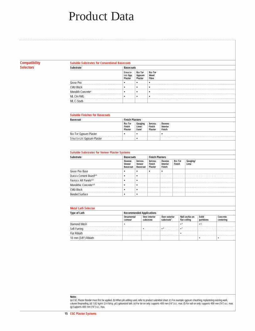
Compatibility Suitable Substrates for Conventional BasecoatsSelectors Substrate Basecoats
STRUCTO- RED TOP RED TOP
LITE Gyp. Gypsum WoodPlaster Plaster Fibre
GRAND PRIX • • •CMU Block • • •Monolith Concretea • • •ML CH-FMG • • •ML C-Studs
Suitable Finishes for BasecoatsBasecoat Finish Plasters
RED TOP Gauging IMPERIAL DIAMOND
Finish Lime/ Finish InteriorPlaster Sand Plaster Finish
RED TOP Gypsum Plaster • • •STRUCTO-LITE Gypsum Plaster •
Suitable Substrates for Veneer Plaster SystemsSubstrate Basecoats Finish Plasters
DIAMOND IMPERIAL IMPERIAL DIAMOND RED TOP Gauging/Veneer Veneer Finish Interior Finish LimeBasecoat Basecoat Plaster Finish
GRAND PRIX Base • • • •DUROCK Cement Boarda,b • •FIBEROCK AR Panelsa,b • •Monolithic Concretea,b • •CMU Block • •Bonded Surface • •
Metal Lath SelectorType of Lath Recommended Applications
Ornamental Over interior Over exterior Nail-on/tie-on Solid Concretecontour substrate substratec flat ceiling partitions centering
Diamond Mesh • •e •g
Self-Furring • •d •f
Flat Riblath •
10 mm (3/8�) Riblath • •
Notes(a) CGC Plaster Bonder must first be applied. (b) When job adding sand, refer to product submittal sheet. (c) For example: gypsum sheathing, replastering existing work,column fireproofing. (d) 1.82 kg/m2 (3.4 lb/sq. yd.) galvanized lath. (e) For tie-on only: supports 400 mm (16�) o.c. max. (f) For nail-on only: supports 400 mm (16�) o.c. max.(g) Supports 400 mm (16�) o.c. max.
16 CGC Plaster Systems
Product Data
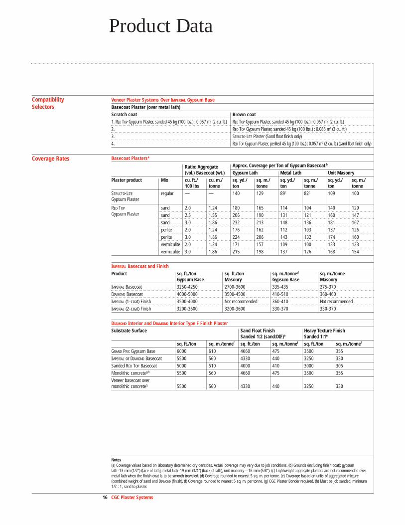
Compatibility Veneer Plaster Systems Over IMPERIAL Gypsum BaseSelectors Basecoat Plaster (over metal lath)
Scratch coat Brown coat1. RED TOP Gypsum Plaster, sanded 45 kg (100 lbs.) : 0.057 m3 (2 cu. ft.) RED TOP Gypsum Plaster, sanded 45 kg (100 lbs.) : 0.057 m3 (2 cu. ft.)
2. RED TOP Gypsum Plaster, sanded 45 kg (100 lbs.) : 0.085 m3 (3 cu. ft.)
3. STRUCTO-LITE Plaster (Sand float finish only)
4. RED TOP Gypsum Plaster, perlited 45 kg (100 lbs.) : 0.057 m3 (2 cu. ft.) (sand float finish only)
Coverage Rates Basecoat Plastersa
Ratio: Aggregate Approx. Coverage per Ton of Gypsum Basecoat b
(vol.) Basecoat (wt.) Gypsum Lath Metal Lath Unit MasonryPlaster product Mix cu. ft./ cu. m./ sq. yd./ sq. m./ sq. yd./ sq. m./ sq. yd./ sq. m./
100 lbs tonne ton tonne ton tonne ton tonneSTRUCTO-LITE regular — — 140 129 89c 82c 109 100Gypsum Plaster
RED TOP sand 2.0 1.24 180 165 114 104 140 129Gypsum Plaster sand 2.5 1.55 206 190 131 121 160 147
sand 3.0 1.86 232 213 148 136 181 167
perlite 2.0 1.24 176 162 112 103 137 126
perlite 3.0 1.86 224 206 143 132 174 160
vermiculite 2.0 1.24 171 157 109 100 133 123
vermiculite 3.0 1.86 215 198 137 126 168 154
IMPERIAL Basecoat and Finish Product sq. ft./ton sq. ft./ton sq. m./tonned sq. m./tonne
Gypsum Base Masonry Gypsum Base MasonryIMPERIAL Basecoat 3250-4250 2700-3600 335-435 275-370
DIAMOND Basecoat 4000-5000 3500-4500 410-510 360-460
IMPERIAL (1-coat) Finish 3500-4000 Not recommended 360-410 Not recommended
IMPERIAL (2-coat) Finish 3200-3600 3200-3600 330-370 330-370
DIAMOND Interior and DIAMOND Interior Type F Finish Plaster Substrate Surface Sand Float Finish Heavy Texture Finish
Sanded 1:2 (sand:DIF)e Sanded 1:1e
sq. ft./ton sq. m./tonnef sq. ft./ton sq. m./tonnef sq. ft./ton sq. m./tonnef
GRAND PRIX Gypsum Base 6000 610 4660 475 3500 355
IMPERIAL or DIAMOND Basecoat 5500 560 4330 440 3250 330
Sanded RED TOP Basecoat 5000 510 4000 410 3000 305
Monolithic concreteg,h 5500 560 4660 475 3500 355
Veneer basecoat overmonolithic concreteg 5500 560 4330 440 3250 330
Notes(a) Coverage values based on laboratory determined dry densities. Actual coverage may vary due to job conditions. (b) Grounds (including finish coat): gypsumlath–13 mm (1/2�) (face of lath), metal lath–19 mm (3/4�) (back of lath), unit masonry—16 mm (5/8�). (c) Lightweight aggregate plasters are not recommended overmetal lath when the finish coat is to be smooth troweled. (d) Coverage rounded to nearest 5 sq. m. per tonne. (e) Coverage based on units of aggregated mixture (combined weight of sand and DIAMOND (finish). (f) Coverage rounded to nearest 5 sq. m. per tonne. (g) CGC Plaster Bonder required. (h) Must be job sanded, minimum1/2 : 1, sand to plaster.

17 CGC Plaster Systems17 CGC Plaster Systems17 CGC Plaster Systems
Coverage Rates Gauging PlastersProduct Finish Texture Gauging to Lime, Approx. Coverage
to Sand (dry wt.) per tonne (sq. m.)per Ton (sq. yds.)a
Lime Finish smooth trowel-extremely hard surface 45 kg (100 lbs.) gauging 350 (380)
45 kg (100 lbs.) lime
smooth trowel-hard surface 45 kg (100 lbs.) gauging 396 (430)
90 kg (200 lbs.) lime
RED TOP, smooth trowel 22.5 kg (50 lbs.) gauging 359 (390)Gauging Plaster and Lime Finish 45 kg (100 lbs.) lime
RED TOP, float finish 22.5 kg (50 lbs.) gauging 258 (280)Gauging Plaster, Lime 45 kg (100 lbs.) limeand Sand Finish 180 kg (400 lbs.) sandb
Coverage Rates Use of Aggregates with Gypsum Plasters Maximum Recommended ProportionsMaximum Aggregate Quantity, cu. ft., to be used with 45 kg (100 lb.) of Neat Gypsum PlasterUnder smooth trowel finishes Under texture finishesSandc Perlited Sandc Perlited
Plaster No. of Type of cu. ft./ cu. m/tonne cu. ft./ cu. m/tonne cu. ft./ cu. m/tonne cu. ft./ cu. m/tonneBase Coats Coats 45 kg (100 lb) 45 kg (100 lb) 45 kg (100 lb) 45 kg (100 lb)gypsum lath 3 scratch 2 1.35 2 1.35 2 1.35 2 1.35
brown 3 2.02 2 1.35 3 2.02 3f 2.02e
2 basecoat 2.5 1.68 2 1.35 2.5 1.68 2 1.35
metal lath 3 scratch 2 1.35 — — 2 1.35 2 1.35
brown 3 2.02 — — 3 2.02 2 1.35
unit masonry 3 scratch 3 2.02 3 2.02 3 2.02 3 2.02
brown 3 2.02 3 2.02 3 2.02 3 2.02
2 basecoat 3 2.02 3 2.02 3 2.02 3 2.02
Notes(a) 1.5 mm (1⁄16�) thick. (b) Mixtures with less or more sand (1:2:1 to 1:2:8) are acceptable, but coverage will vary. (c) Approximately six No. 2 shovels of sand equal0.028m3 (1 cu. ft.). (d) In a construction with metal lath as the plaster base, perlite or vermiculite aggregate is not recommended for use in the basecoat plaster, unless afloat finish is used. (e) Quantity recommended only if plaster is applied 25 mm (1�) thick; otherwise use 0.057m3 (2 cu. ft.)
18 CGC Plaster Systems18 CGC Plaster Systems
Product Data
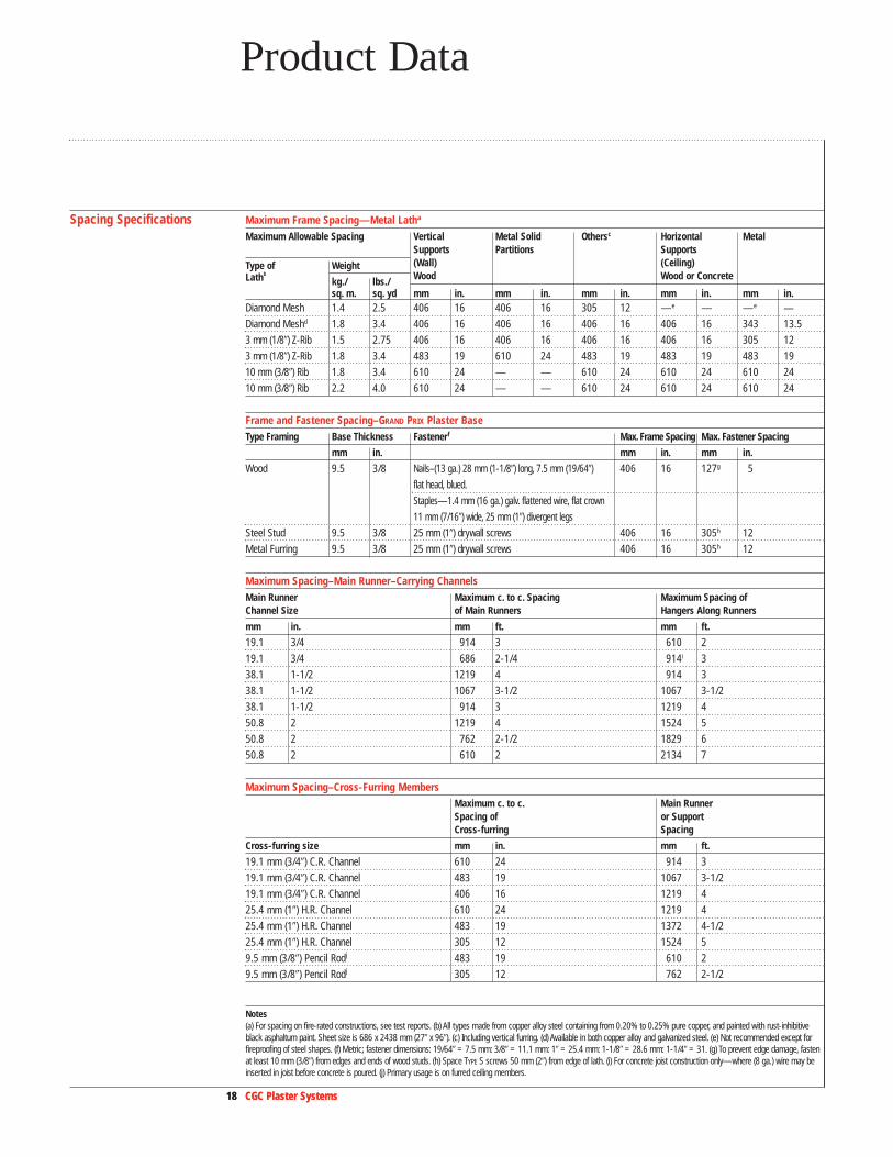
Spacing Specifications Maximum Frame Spacing—Metal Latha
Maximum Allowable Spacing Vertical Metal Solid Othersc Horizontal MetalSupports Partitions Supports
Type of Weight (Wall) (Ceiling) Lathb
kg./ lbs./ Wood Wood or Concrete
sq. m. sq. yd mm in. mm in. mm in. mm in. mm in.Diamond Mesh 1.4 2.5 406 16 406 16 305 12 —e — —e —
Diamond Meshd 1.8 3.4 406 16 406 16 406 16 406 16 343 13.5
3 mm (1/8�) Z-Rib 1.5 2.75 406 16 406 16 406 16 406 16 305 12
3 mm (1/8�) Z-Rib 1.8 3.4 483 19 610 24 483 19 483 19 483 19
10 mm (3/8�) Rib 1.8 3.4 610 24 — — 610 24 610 24 610 24
10 mm (3/8�) Rib 2.2 4.0 610 24 — — 610 24 610 24 610 24
Frame and Fastener Spacing–GRAND PRIX Plaster BaseType Framing Base Thickness Fastenerf Max. Frame Spacing Max. Fastener Spacing
mm in. mm in. mm in.
Wood 9.5 3/8 Nails–(13 ga.) 28 mm (1-1/8�) long, 7.5 mm (19/64�) 406 16 127g 5
flat head, blued.
Staples—1.4 mm (16 ga.) galv. flattened wire, flat crown
11 mm (7/16�) wide, 25 mm (1�) divergent legs
Steel Stud 9.5 3/8 25 mm (1�) drywall screws 406 16 305h 12
Metal Furring 9.5 3/8 25 mm (1�) drywall screws 406 16 305h 12
Maximum Spacing–Main Runner–Carrying ChannelsMain Runner Maximum c. to c. Spacing Maximum Spacing of Channel Size of Main Runners Hangers Along Runners
mm in. mm ft. mm ft.
19.1 3/4 914 3 610 2
19.1 3/4 686 2-1/4 914i 3
38.1 1-1/2 1219 4 914 3
38.1 1-1/2 1067 3-1/2 1067 3-1/2
38.1 1-1/2 914 3 1219 4
50.8 2 1219 4 1524 5
50.8 2 762 2-1/2 1829 6
50.8 2 610 2 2134 7
Maximum Spacing–Cross-Furring MembersMaximum c. to c. Main Runner Spacing of or Support Cross-furring Spacing
Cross-furring size mm in. mm ft.
19.1 mm (3/4�) C.R. Channel 610 24 914 3
19.1 mm (3/4�) C.R. Channel 483 19 1067 3-1/2
19.1 mm (3/4�) C.R. Channel 406 16 1219 4
25.4 mm (1�) H.R. Channel 610 24 1219 4
25.4 mm (1�) H.R. Channel 483 19 1372 4-1/2
25.4 mm (1�) H.R. Channel 305 12 1524 5
9.5 mm (3/8�) Pencil Rodj 483 19 610 2
9.5 mm (3/8�) Pencil Rodj 305 12 762 2-1/2
Notes(a) For spacing on fire-rated constructions, see test reports. (b) All types made from copper alloy steel containing from 0.20% to 0.25% pure copper, and painted with rust-inhibitiveblack asphaltum paint. Sheet size is 686 x 2438 mm (27� x 96�). (c) Including vertical furring. (d) Available in both copper alloy and galvanized steel. (e) Not recommended except forfireproofing of steel shapes. (f) Metric; fastener dimensions: 19/64� = 7.5 mm: 3/8� = 11.1 mm: 1� = 25.4 mm: 1-1/8� = 28.6 mm: 1-1/4� = 31. (g) To prevent edge damage, fastenat least 10 mm (3/8�) from edges and ends of wood studs. (h) Space TYPE S screws 50 mm (2�) from edge of lath. (i) For concrete joist construction only—where (8 ga.) wire may beinserted in joist before concrete is poured. (j) Primary usage is on furred ceiling members.
19 CGC Plaster Systems19 CGC Plaster Systems19 CGC Plaster Systems
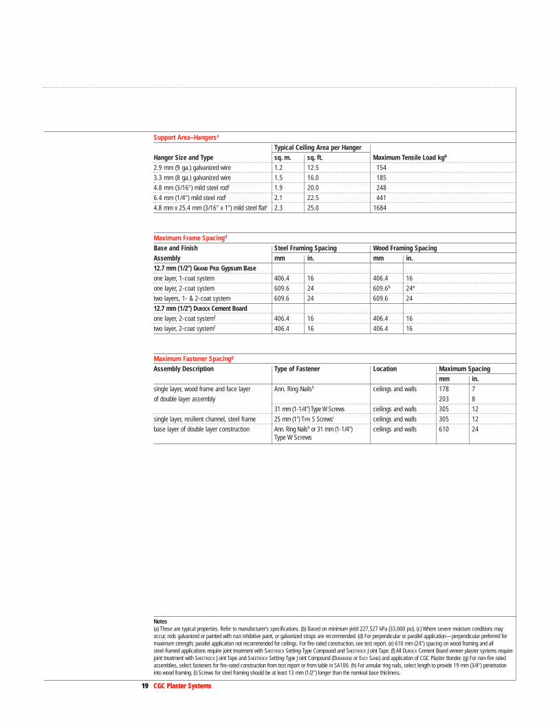
Support Area–Hangersa
Typical Ceiling Area per HangerHanger Size and Type sq. m. sq. ft. Maximum Tensile Load kgb
2.9 mm (9 ga.) galvanized wire 1.2 12.5 154
3.3 mm (8 ga.) galvanized wire 1.5 16.0 185
4.8 mm (3/16�) mild steel rodc 1.9 20.0 248
6.4 mm (1/4�) mild steel rodc 2.1 22.5 441
4.8 mm x 25.4 mm (3/16� x 1�) mild steel flatc 2.3 25.0 1684
Maximum Frame Spacingd
Base and Finish Steel Framing Spacing Wood Framing SpacingAssembly mm in. mm in.12.7 mm (1/2��) GRAND PRIX Gypsum Baseone layer, 1-coat system 406.4 16 406.4 16
one layer, 2-coat system 609.6 24 609.6b 24e
two layers, 1- & 2-coat system 609.6 24 609.6 24
12.7 mm (1/2��) DUROCK Cement Boardone layer, 2-coat systemf 406.4 16 406.4 16
two layer, 2-coat systemf 406.4 16 406.4 16
Maximum Fastener Spacingg
Assembly Description Type of Fastener Location Maximum Spacingmm in.
single layer, wood frame and face layer Ann. Ring Nailsh ceilings and walls 178 7
of double layer assembly 203 8
31 mm (1-1/4�) Type W Screws ceilings and walls 305 12
single layer, resilient channel, steel frame 25 mm (1�) TYPE S Screwsi ceilings and walls 305 12
base layer of double layer construction Ann. Ring Nailsh or 31 mm (1-1/4�) ceilings and walls 610 24Type W Screws
Notes(a) These are typical properties. Refer to manufacturer’s specifications. (b) Based on minimum yield 227,527 kPa (33,000 psi). (c) Where severe moisture conditions mayoccur, rods galvanized or painted with rust-inhibitive paint, or galvanized straps are recommended. (d) For perpendicular or parallel application—perpendicular preferred formaximum strength; parallel application not recommended for ceilings. For fire-rated construction, see test report. (e) 610 mm (24�) spacing on wood framing and allsteel-framed applications require joint treatment with SHEETROCK Setting-Type Compound and SHEETROCK Joint Tape. (f) All DUROCK Cement Board veneer plaster systems requirejoint treatment with SHEETROCK Joint Tape and SHEETROCK Setting-Type Joint Compound (DURABOND or EASY SAND) and application of CGC Plaster Bonder. (g) For non-fire ratedassemblies, select fasteners for fire-rated construction from test report or from table in SA100. (h) For annular ring nails, select length to provide 19 mm (3/4�) penetrationinto wood framing. (i) Screws for steel framing should be at least 13 mm (1/2�) longer than the nominal base thickness.
20 CGC Plaster Systems20 CGC Plaster Systems
Performance Testing
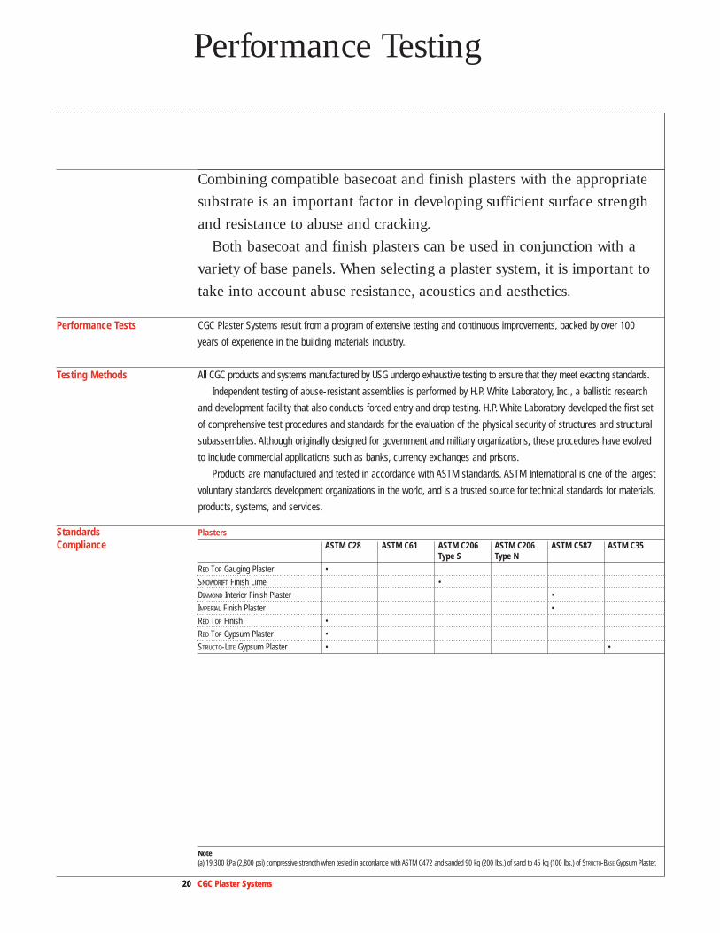
Combining compatible basecoat and finish plasters with the appropriatesubstrate is an important factor in developing sufficient surface strengthand resistance to abuse and cracking.
Both basecoat and finish plasters can be used in conjunction with avariety of base panels. When selecting a plaster system, it is important totake into account abuse resistance, acoustics and aesthetics.
Performance Tests CGC Plaster Systems result from a program of extensive testing and continuous improvements, backed by over 100
years of experience in the building materials industry.
Testing Methods All CGC products and systems manufactured by USG undergo exhaustive testing to ensure that they meet exacting standards.
Independent testing of abuse-resistant assemblies is performed by H.P. White Laboratory, Inc., a ballistic research
and development facility that also conducts forced entry and drop testing. H.P. White Laboratory developed the first set
of comprehensive test procedures and standards for the evaluation of the physical security of structures and structural
subassemblies. Although originally designed for government and military organizations, these procedures have evolved
to include commercial applications such as banks, currency exchanges and prisons.
Products are manufactured and tested in accordance with ASTM standards. ASTM International is one of the largest
voluntary standards development organizations in the world, and is a trusted source for technical standards for materials,
products, systems, and services.
Standards PlastersCompliance ASTM C28 ASTM C61 ASTM C206 ASTM C206 ASTM C587 ASTM C35
Type S Type NRED TOP Gauging Plaster •
SNOWDRIFT Finish Lime •
DIAMOND Interior Finish Plaster •
IMPERIAL Finish Plaster •
RED TOP Finish •
RED TOP Gypsum Plaster •
STRUCTO-LITE Gypsum Plaster • •
Note (a) 19,300 kPa (2,800 psi) compressive strength when tested in accordance with ASTM C472 and sanded 90 kg (200 lbs.) of sand to 45 kg (100 lbs.) of STRUCTO-BASE Gypsum Plaster.

21 CGC Plaster Systems21 CGC Plaster Systems21 CGC Plaster Systems
Standards SubstratesCompliance ASTM C37 ASTM C588 ASTM E84 ASTM E119a ASTM E136 ASTM C1278
FIBEROCK Interior AQUA-TOUGH Panels • •b •
IMPERIAL Gypsum Base • • • •
Fixture Attachment Load TableFastener Type Size Base Assembly Allowable Withdrawal Allowable Shear
Resistance Resistancemm in. Nc lbs. Nc lbs.
toggle bolt or hollow wall fastener 3.18 1/8 13 mm (1/2�) gypsum base 89 20 178 40
4.76 3/16 134 30 223 50
6.35 1/4 178 40 267 60
3.18 1/8 13 mm (1/2�) gypsum base and 312 70 445 100
4.76 3/16 0.5 mm (25 ga.)steel stud 356 80 556 125
6.35 1/4 690 155 779 175
No. 8 sheet metal screw 13 mm (1/2�) gypsum base and 0.5 mm (25 ga.) 223 50 356 80
TYPE S bugle head screw steel stud or 0.5 mm (25 ga.) steel insert 267 60 445 100
TYPE S-12 bugle head screw 13 mm (1/2�) gypsum base and 0.8 mm (20 ga.) 378 85 601 135steel stud or 0.8 mm (20 ga.) steel insert
10 mm (3/8�) TYPE S pan head screw 0.5 mm (25 ga.) steel to 0.5 mm (25 ga.) steel 312 70 534 120
two bolts welded to steel insert 4.76 3/16 grab bar attachment 779 175 890 200
6.35 1/4 890 200 1113 250
bolt welded to 38 mm (1-1⁄2�) chan. 6.35 1/4 plumber’s bracket 890 200 1113 250
Dimensional StabilityHygrometric Coefficient of Expansion Thermal Coefficient of Expansion(unrestrained) (unrestrained)[mm/mm/%R.H.(5%–90% R.H.)] [mm/mm/C°(4-38°F)]
STRUCTO-LITE Plaster (regular) 4.8x10⁻⁶ 13.1x10⁻⁶
Sanded Gypsum Plaster (100:2, 100:3) 1.5x10⁻⁶ 12.6x10⁻⁶
Gypsum Lath 7.2x10⁻⁶ 16.2x10⁻⁶
Vermiculite Gypsum Plaster (100:2) 3.8x10⁻⁶ —
Basecoat PlastersRatio: Aggregate (vol.) Approximate Weight ConductivityBasecoat (wt.) Compressive Strength Dryd
Plaster Product Mix cu. m/tonne cu. ft./45 kg psi kg/sq. cm. pcf–dry (k)RED TOP Gypsum sand 1.14 2.0 62 875 107 5.51Plaster sand 1.43 2.5 53 750 108 —
sand 1.71 3.0 46 650 109 5.60
perlite 1.14 2.0 49 700 48 1.64
perlite 1.71 3.0 37 525 41 1.31
vermiculite 1.14 2.0 33 465 48 1.74
vermiculite 1.71 3.0 20 290 41 1.42
Note(a) When tested as part of an assembly. (b) 15.9 mm (5/8�) thick panel. (c) Newtons. (d) Average laboratory results when tested in accordance with ASTM C472. Figuresmay vary slightly for products from individual plants.

22 CGC Plaster Systems
Performance Selector
Steel FramedPartitions
1 Hour Fire-rated Construction Non-loadbearing Acoustical Performance Reference
Construction Detail Description Test Number STC Test Number ARL Index
wt. 6 • 15.9 mm (5/8�) GRAND PRIX FIRECODE Core ULC Des W453 SA700 1Gypsum Base or GRAND PRIX FIRECODE Core or W407 SA920Abuse- Resistant Gypsum Base or or UL Des U419FIBEROCK Panels or U465
– 92 mm (3-5/8�) 0.5 mm (25 gauge) steel studs 610 mm (24�) o.c.
• optional veneer plaster
wt. 6 • 15.9 mm (5/8�) GRAND PRIX FIRECODE Core UL Des U404 SA920 2Gypsum Base one side SA934
– 89 mm (3-1/2�) 0.8 mm (20 gauge) steel studs 400 mm (16�) o.c.
• 12.7 mm (1/2�) DUROCK Cement Board other side– 75 mm (3�) SAFB• CGC Plaster Bonder over cement board and
treated joints• joints treated with CGC setting-type joint
compound and paper tape• DIAMOND veneer basecoat with IMPERIAL finish plaster
wt. 6 • 15.9 mm (5/8�) DUROCK Cement Board or 15.9 mm UL Des U407 SA920 3(5/8�) GRAND PRIX FIRECODE Core Gypsum Base SA934
– 89 mm (3-1/2�) 0.8 mm (20 gauge) studs, 400 mm (16�) o.c.– 75 mm (3�) SAFB• CGC Plaster Bonder over untreated joint areas• joints treated with CGC setting-type joint
compound and paper tape• CGC Plaster Bonder over cement board and
treated joints• DIAMOND veneer basecoat with veneer or
conventional finish
wt. 7 • 12.7 mm (1/2�) GRAND PRIX FIRECODE C Core ULC Des W453 SA920 4Gypsum Panels or UL Des U419
– 64 mm (2-1/2�) 0.5 mm (25 gauge) steel studs 610 mm (24�) o.c. or U448 – 38 mm (1-1/2�) SAFB– joints finished• optional veneer finish
wt. 5 • 12.7 mm (1/2�) GRAND PRIX FIRECODE C Core ULC Des W453 SA920 5Gypsum Base or W408
– 92 mm (3-5/8�) 0.5 mm (25 gauge) steel or UL Des U419studs 610 mm (24�) o.c. or U451
– 75 mm (3�) SAFB– Resilient channel one side spaced – 610 mm (24�) o.c.• optional veneer plaster
130 mm(51⁄8")
100 mm(4")
121 mm(43⁄4")
117 mm(45⁄8")
124 mm(47⁄8")
40 USG-860808
49 SA-870717Based on 75 mm (3�) SAFB in cavity
51 RAL-TL-90-166 Based on 15.9 mm (5/8�) FIRECODE C Core panelsand 75 mm (3�) SAFB, and veneer finish surfaceSAFB 625 mm (25�) wide, creased to fit cavity
41 RAL-TL-69-148Based on same construction without THERMAFIBER SAFB
50 SA-800504
50 RAL-TL-87-156
54 RAL-TL-83-216Based on 15.9 mm (5/8�) thick panels
NoteAll products are not available in all markets. Consult yourCGC Sales Representative for details.
23 CGC Plaster Systems
Steel FramedPartitions
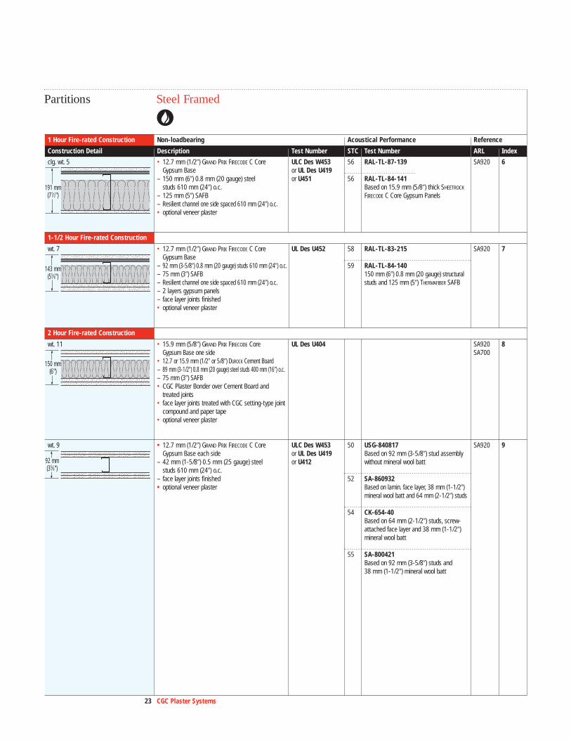
56 RAL-TL-87-139
56 RAL-TL-84-141Based on 15.9 mm (5/8�) thick SHEETROCK
FIRECODE C Core Gypsum Panels
58 RAL-TL-83-215
59 RAL-TL-84-140150 mm (6�) 0.8 mm (20 gauge) structural studs and 125 mm (5�) THERMAFIBER SAFB
50 USG-840817Based on 92 mm (3-5/8�) stud assemblywithout mineral wool batt
52 SA-860932Based on lamin. face layer, 38 mm (1-1/2�)mineral wool batt and 64 mm (2-1/2�) studs
54 CK-654-40Based on 64 mm (2-1/2�) studs, screw-attached face layer and 38 mm (1-1/2�)mineral wool batt
55 SA-800421Based on 92 mm (3-5/8�) studs and38 mm (1-1/2�) mineral wool batt
1 Hour Fire-rated Construction Non-loadbearing Acoustical Performance Reference
Construction Detail Description Test Number STC Test Number ARL Index
clg. wt. 5 • 12.7 mm (1/2�) GRAND PRIX FIRECODE C Core ULC Des W453 SA920 6Gypsum Base or UL Des U419
– 150 mm (6�) 0.8 mm (20 gauge) steel or U451studs 610 mm (24�) o.c.
– 125 mm (5�) SAFB– Resilient channel one side spaced 610 mm (24�) o.c.• optional veneer plaster
1-1/2 Hour Fire-rated Construction
wt. 7 • 12.7 mm (1/2�) GRAND PRIX FIRECODE C Core UL Des U452 SA920 7Gypsum Base
– 92 mm (3-5/8�) 0.8 mm (20 gauge) studs 610 mm (24�) o.c.– 75 mm (3�) SAFB– Resilient channel one side spaced 610 mm (24�) o.c.– 2 layers gypsum panels – face layer joints finished• optional veneer plaster
2 Hour Fire-rated Construction
wt. 11 • 15.9 mm (5/8�) GRAND PRIX FIRECODE Core UL Des U404 SA920 8Gypsum Base one side SA700
• 12.7 or 15.9 mm (1/2� or 5/8�) DUROCK Cement Board – 89 mm (3-1/2�) 0.8 mm (20 gauge) steel studs 400 mm (16�) o.c.– 75 mm (3�) SAFB• CGC Plaster Bonder over Cement Board and
treated joints• face layer joints treated with CGC setting-type joint
compound and paper tape• optional veneer plaster
wt. 9 • 12.7 mm (1/2�) GRAND PRIX FIRECODE C Core ULC Des W453 SA920 9Gypsum Base each side or UL Des U419
– 42 mm (1-5/8�) 0.5 mm (25 gauge) steel or U412studs 610 mm (24�) o.c.
– face layer joints finished• optional veneer plaster
92 mm(35⁄8")
150 mm(6")
143 mm(55⁄8")
191 mm(71⁄2")
24 CGC Plaster Systems
Performance Selector
Steel FramedPartitions
2 Hour Fire-rated Construction Non-loadbearing Acoustical Performance Reference
Construction Detail Description Test Number STC Test Number ARL Index
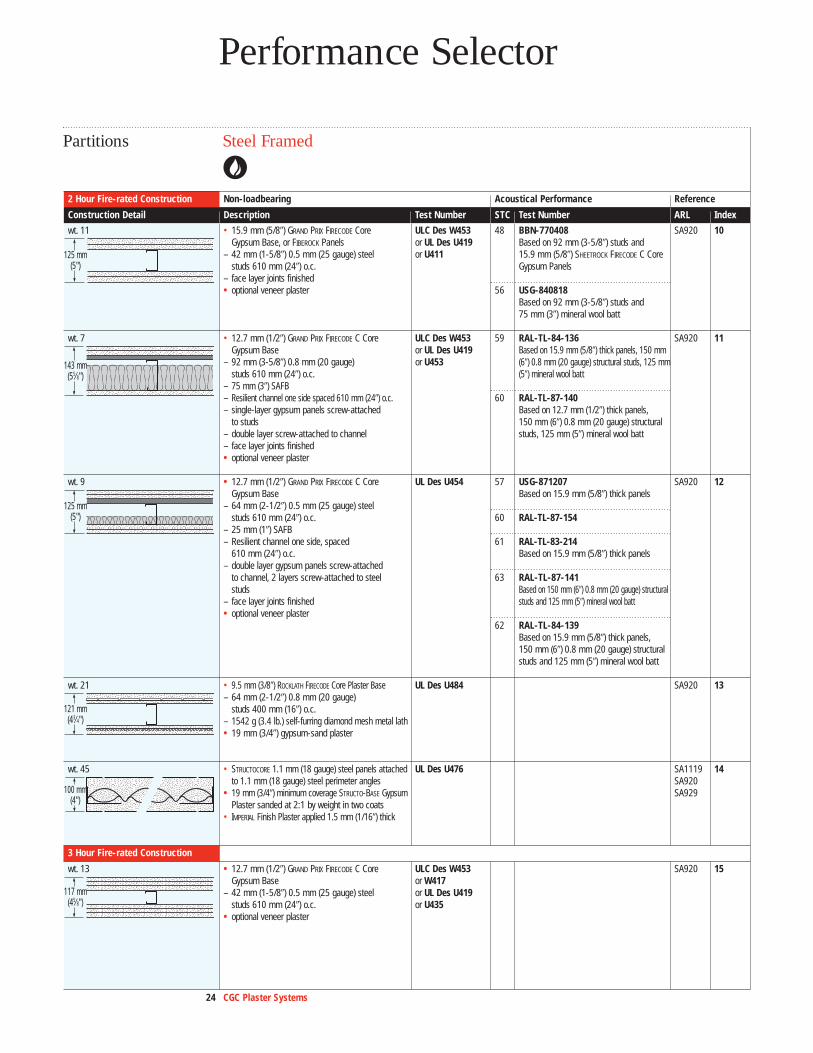
wt. 11 • 15.9 mm (5/8�) GRAND PRIX FIRECODE Core ULC Des W453 SA920 10Gypsum Base, or FIBEROCK Panels or UL Des U419
– 42 mm (1-5/8�) 0.5 mm (25 gauge) steel or U411studs 610 mm (24�) o.c.
– face layer joints finished• optional veneer plaster
wt. 7 • 12.7 mm (1/2�) GRAND PRIX FIRECODE C Core ULC Des W453 SA920 11Gypsum Base or UL Des U419
– 92 mm (3-5/8�) 0.8 mm (20 gauge) or U453studs 610 mm (24�) o.c.
– 75 mm (3�) SAFB– Resilient channel one side spaced 610 mm (24�) o.c.– single-layer gypsum panels screw-attached
to studs– double layer screw-attached to channel– face layer joints finished• optional veneer plaster
wt. 9 • 12.7 mm (1/2�) GRAND PRIX FIRECODE C Core UL Des U454 SA920 12Gypsum Base
– 64 mm (2-1/2�) 0.5 mm (25 gauge) steel studs 610 mm (24�) o.c.
– 25 mm (1�) SAFB– Resilient channel one side, spaced
610 mm (24�) o.c.– double layer gypsum panels screw-attached
to channel, 2 layers screw-attached to steel studs
– face layer joints finished• optional veneer plaster
wt. 21 • 9.5 mm (3/8�) ROCKLATH FIRECODE Core Plaster Base UL Des U484 SA920 13– 64 mm (2-1/2�) 0.8 mm (20 gauge)
studs 400 mm (16�) o.c.– 1542 g (3.4 lb.) self-furring diamond mesh metal lath• 19 mm (3/4�) gypsum-sand plaster
wt. 45 • STRUCTOCORE 1.1 mm (18 gauge) steel panels attached UL Des U476 SA1119 14to 1.1 mm (18 gauge) steel perimeter angles SA920
• 19 mm (3/4�) minimum coverage STRUCTO-BASE Gypsum SA929Plaster sanded at 2:1 by weight in two coats
• IMPERIAL Finish Plaster applied 1.5 mm (1/16�) thick
3 Hour Fire-rated Construction
wt. 13 • 12.7 mm (1/2�) GRAND PRIX FIRECODE C Core ULC Des W453 SA920 15Gypsum Base or W417
– 42 mm (1-5/8�) 0.5 mm (25 gauge) steel or UL Des U419studs 610 mm (24�) o.c. or U435
• optional veneer plaster
117 mm(45⁄8")
100 mm(4")
121 mm(43⁄4")
125 mm(5")
143 mm(55⁄8")
125 mm(5")
48 BBN-770408Based on 92 mm (3-5/8�) studs and15.9 mm (5/8�) SHEETROCK FIRECODE C CoreGypsum Panels
56 USG-840818Based on 92 mm (3-5/8�) studs and75 mm (3�) mineral wool batt
59 RAL-TL-84-136Based on 15.9 mm (5/8�) thick panels, 150 mm(6�) 0.8 mm (20 gauge) structural studs, 125 mm(5�) mineral wool batt
60 RAL-TL-87-140Based on 12.7 mm (1/2�) thick panels,150 mm (6�) 0.8 mm (20 gauge) structuralstuds, 125 mm (5�) mineral wool batt
57 USG-871207Based on 15.9 mm (5/8�) thick panels
60 RAL-TL-87-154
61 RAL-TL-83-214Based on 15.9 mm (5/8�) thick panels
63 RAL-TL-87-141 Based on 150 mm (6�) 0.8 mm (20 gauge) structuralstuds and 125 mm (5�) mineral wool batt
62 RAL-TL-84-139 Based on 15.9 mm (5/8�) thick panels,150 mm (6�) 0.8 mm (20 gauge) structuralstuds and 125 mm (5�) mineral wool batt
25 CGC Plaster Systems
Steel FramedPartitions
2 Hour Fire-rated Construction Non-loadbearing Acoustical Performance Reference
Construction Detail Description Test Number STC Test Number ARL Index
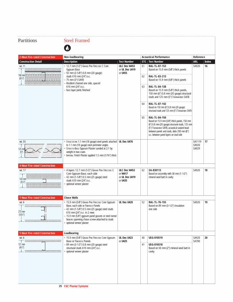
61 RAL-TL-87-153Based on 15.9 mm (5/8�) thick panels
62 RAL-TL-83-213Based on 15.9 mm (5/8�) thick panels
63 RAL-TL-84-138Based on 15.9 mm (5/8�) thick panels,150 mm (6�) 0.8 mm (20 gauge) structuralstuds and 125 mm (5�) THERMAFIBER SAFB
64 RAL-TL-87-142Based on 150 mm (6�) 0.8 mm (20 gauge)structural studs and 125 mm (5�) THERMAFIBER SAFB
65 RAL-TL-84-150Based on 15.9 mm (5/8�) thick panels, 150 mm(6�) 0.8 mm (20 gauge) structural studs, 125 mm(5�) THERMAFIBER SAFB, acoustical sealant beadbetween panels and studs, dabs 200 mm (8�)o.c. between panel layers on stud side
62 SA-830113Based on assembly with 38 mm (1-1/2�)mineral wool batt in cavity
52 RAL-TL-76-155Based on 89 mm (3-1/2�) insulation one side
40 USG-810519
41 USG-810518Based on 50 mm (2�) mineral wool batt in cavity
wt. 11 • 12.7 mm (1/2�) GRAND PRIX FIRECODE C Core ULC Des W453 SA920 16Gypsum Base or UL Des U419
– 92 mm (3-5/8�) 0.8 mm (20 gauge) or U455studs 610 mm (24�) o.c.
– 75 mm (3�) SAFB– Resilient channel one side, spaced
610 mm (24�) o.c.– face layer joints finished
wt. 55 • STRUCTOCORE 1.1 mm (18 gauge) steel panels attached UL Des U476 SA1119 17to 1.1 mm (18 gauge) steel perimeter angles SA920
• STRUCTO-BASE Gypsum Plaster sanded at 2:1 by SA929 weight in two coats
• IMPERIAL Finish Plaster applied 1.5 mm (1/16�) thick
4 Hour Fire-rated Construction
wt. 17 • 4 layers 12.7 mm (1/2�) GRAND PRIX FIRECODE C ULC Des W453 SA920 18Core Gypsum Base, each side or W417
– 42 mm (1-5/8�) 0.5 mm (25 gauge) steel or UL Des U419studs 610 mm (24�) o.c. or U435
• optional veneer plaster
1 Hour Fire-rated Construction Chase Walls
wt. 6 • 15.9 mm (5/8�) GRAND PRIX FIRECODE Core Gypsum UL Des U420 SA920 19Base, each side or FIBEROCK Panels
– 42 mm (1-5/8�) 0.5 mm (25 gauge) steel studs 610 mm (24�) o.c. in 2 rows
– 15.9 mm (5/8�) gypsum panel gussets or steel runner braces spanning chase screw-attached to studs
• optional veneer plaster
1 Hour Fire-rated Construction Loadbearing
wt. 6 • 15.9 mm (5/8�) GRAND PRIX FIRECODE Core Gypsum UL Des U423 SA920 20Base or FIBEROCK Panels or U425 SA700
– 89 mm (3-1/2�) 0.8 mm (20 gauge) steel structural studs 610 mm (24�) o.c.
• optional veneer plaster
121 mm(43⁄4")
273 mm(103⁄4")
143 mm(55⁄8")
125 mm(5")
168 mm(65⁄8")
26 CGC Plaster Systems
Performance Selector
Steel FramedPartitions
1 Hour Fire-rated Construction Loadbearing (Refer to ULC/UL Design Directory listings for loading conditions. See page 4.) Acoustical Performance Reference
Construction Detail Description Test Number STC Test Number ARL Index
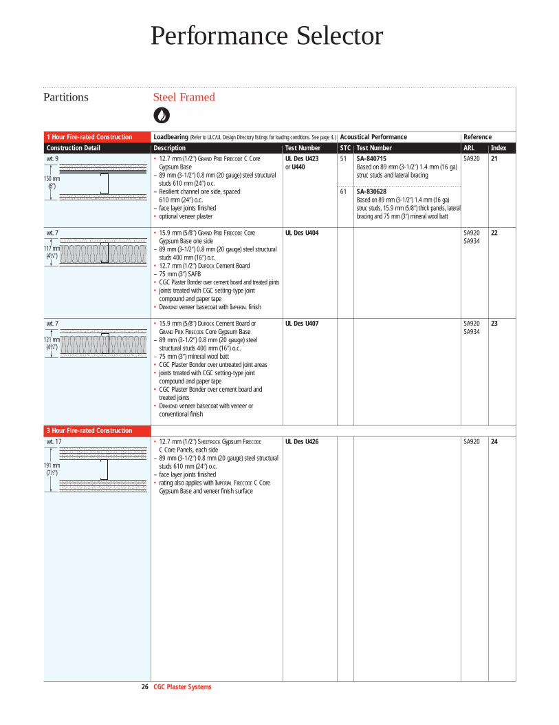
51 SA-840715Based on 89 mm (3-1/2�) 1.4 mm (16 ga)struc studs and lateral bracing
61 SA-830628Based on 89 mm (3-1/2�) 1.4 mm (16 ga)struc studs, 15.9 mm (5/8�) thick panels, lateralbracing and 75 mm (3�) mineral wool batt
wt. 9 • 12.7 mm (1/2�) GRAND PRIX FIRECODE C Core UL Des U423 SA920 21Gypsum Base or U440
– 89 mm (3-1/2�) 0.8 mm (20 gauge) steel structural studs 610 mm (24�) o.c.
– Resilient channel one side, spaced 610 mm (24�) o.c.
– face layer joints finished• optional veneer plaster
wt. 7 • 15.9 mm (5/8�) GRAND PRIX FIRECODE Core UL Des U404 SA920 22Gypsum Base one side SA934
– 89 mm (3-1/2�) 0.8 mm (20 gauge) steel structural studs 400 mm (16�) o.c.
• 12.7 mm (1/2�) DUROCK Cement Board– 75 mm (3�) SAFB• CGC Plaster Bonder over cement board and treated joints• joints treated with CGC setting-type joint
compound and paper tape• DIAMOND veneer basecoat with IMPERIAL finish
wt. 7 • 15.9 mm (5/8�) DUROCK Cement Board or UL Des U407 SA920 23GRAND PRIX FIRECODE Core Gypsum Base SA934
– 89 mm (3-1/2�) 0.8 mm (20 gauge) steel structural studs 400 mm (16�) o.c.
– 75 mm (3�) mineral wool batt• CGC Plaster Bonder over untreated joint areas• joints treated with CGC setting-type joint
compound and paper tape• CGC Plaster Bonder over cement board and
treated joints• DIAMOND veneer basecoat with veneer or
conventional finish
3 Hour Fire-rated Construction
wt. 17 • 12.7 mm (1/2�) SHEETROCK Gypsum FIRECODE UL Des U426 SA920 24C Core Panels, each side
– 89 mm (3-1/2�) 0.8 mm (20 gauge) steel structural studs 610 mm (24�) o.c.
– face layer joints finished• rating also applies with IMPERIAL FIRECODE C Core
Gypsum Base and veneer finish surface
191 mm(71⁄2")
121 mm(43⁄4")
117 mm(45⁄8")
150 mm(6")

27 CGC Plaster Systems
Wood FramedPartitions
1 Hour Fire-rated Construction Loadbearing (Refer to ULC/UL Design Directory listings for loading conditions. See page 4.) Acoustical Performance Reference
Construction Detail Description Test Number STC Test Number ARL Index
34 USG-30-FT-G&H Based on 400 mm (16�) stud spacing and screws 150 mm (6�) o.c.
37 USG-860807Based on 610 mm (24�) stud spacing
46 BBN-700725Based on 610 mm (24�) stud spacing and 75 mm (3�) mineral wool batt
52 USG-810218Based on same assembly (non-fire rated)without mineral wool batt
58 USG-810219
47 NBCC W7a With insulation
wt. 7 • 15.9 mm (5/8�) GRAND PRIX FIRECODE Core ULC Des W301 SA920 25Gypsum Base or FIBEROCK Panels or UL Des U305
– 2x4 wood stud 400 or 610 mm (16� or 24�) o.c. or U314– joints finished– optional veneer plaster
2 Hour Fire-rated Construction
wt. 12 • 15.9 mm (5/8�) GRAND PRIX FIRECODE Core ULC Des U301 SA920 26Gypsum Base or SHEETROCK Water-Resistant or UL Des U301FIRECODE Core Gypsum Panels or FIBEROCK
Panels– 2x4 wood studs 400 mm (16�) o.c.– joints finished• optional veneer plaster
1 Hour Fire-rated Construction Chase Walls
• 15.9 mm (5/8�) GRAND PRIX FIRECODE C Core UL Des U340 SA920 27Gypsum Base
– 2x4 staggered wood stud 610 mm (24�) o.c.on 2x6 common plate
– joints finished• optional veneer plaster
162 mm(63⁄8")
150 mm(6")
121 mm(43⁄4")
28 CGC Plaster Systems
Performance Selector
Steel FramedFloor/Ceilings
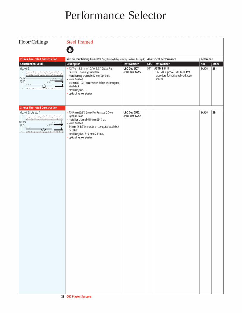
2 Hour Fire-rated Construction Steel Bar Joist Framing (Refer to ULC/UL Design Directory listings for loading conditions. See page 4.) Acoustical Performance Reference
Construction Detail Description Test Number STC Test Number ARL Index
clg. wt. 3 • 12.7 or 15.9 mm (1/2� or 5/8�) GRAND PRIX ULC Des I507 SA920 28FIRECODE C Core Gypsum Base or UL Des G515
– metal furring channel 610 mm (24�) o.c.– joints finished– 64 mm (2-1/2�) concrete on riblath or corrugated
steel deck – steel bar joists• optional veneer plaster
3 Hour Fire-rated Construction
clg. wt. 3, clg. wt. 4 • 15.9 mm (5/8�) GRAND PRIX FIRECODE C Core ULC Des G512 SA920 29Gypsum Base or UL Des G512
– metal fur channel 610 mm (24�) o.c.– joints finished– 64 mm (2-1/2�) concrete on corrugated steel deck
or riblath – steel bar joists, 610 mm (24�) o.c.• optional veneer plaster
406 mm(16")
352 mm(137⁄8")
54* ASTM E1414*CAC value per ASTM E1414 testprocedure for horizontally adjacent spaces
29 CGC Plaster Systems
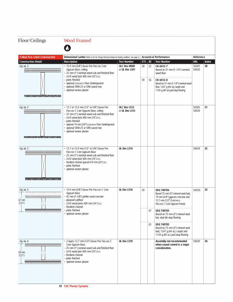
Wood FramedFloor/Ceilings
1 Hour Fire-rated Construction Dimensional Lumber (Refer to ULC/UL Design Directory listings for loading conditions. See page 4.) Acoustical Performance Reference
Construction Detail Description Test Number STC IIC Test Number ARL Index
clg. wt. 3 • 15.9 mm (5/8�) GRAND PRIX FIRECODE Core ULC Des M500 SA305 30Gypsum Base, ceiling or UL Des L501 SA920
– 25 mm (1�) nominal wood sub and finished floor– 2x10 wood joist 400 mm (16�) o.c.– joints finished• optional LEVELROCK Floor Underlayment• optional SRM-25 or SRB sound mat• optional veneer plaster
clg. wt. 3 • 12.7 or 15.9 mm (1/2� or 5/8�) GRAND PRIX ULC Des L512 SA305 31FIRECODE C Core Gypsum Base, ceiling or UL Des L512 SA920
– 25 mm (1�) nominal wood sub and finished floor– 2x10 wood joist 400 mm (16�) o.c.– joints finished• optional 19 mm (3/4�) LEVELROCK Floor Underlayment• optional SRM-25 or SRB sound mat• optional veneer plaster
clg. wt. 3 • 12.7 or 15.9 mm (1/2� or 5/8�) GRAND PRIX UL Des L514 SA920 32FIRECODE C Core Gypsum Base
– 25 mm (1�) nominal wood sub and finished floor– 2x10 wood joist 400 mm (16�) o.c.– Resilient channel spaced 610 mm (24�) o.c.– joints finished• optional veneer plaster
clg. wt. 3 • 15.9 mm (5/8�) GRAND PRIX FIRECODE C Core UL Des L516 33Gypsum Base
– 42 mm (1-5/8�) perlite-sand concrete– plywood subfloor– 2x10 wood joists 400 mm (16�) o.c.– Resilient channel – joints finished• optional veneer plaster
clg. wt. 4 • 2 layers 12.7 mm (1/2�) GRAND PRIX FIRECODE C UL Des L510 Assembly not recommended SA920 34Core Gypsum Base when sound control is a major
– 25 mm (1�) nominal wood sub and finished floor consideration.– 2x10 wood joist 400 mm (16�) o.c.– Resilient channel – joints finished• optional veneer plaster
343 mm(131⁄2")
321 mm(125⁄8")
38 32 CK-6412-7Based on 31 mm (1-1/4�) nominal wood floor
39 56 CK-6412-8Based on 31 mm (1-1/4�) nominal woodfloor, 1247 g (44 oz) carpet and 1134 g (40 oz) pad atop flooring
59 USG 740704 SA920Based 75 mm (3�) mineral wool batt,19 mm (3/4�) gypsum concrete and 12.7 mm (1/2�) SHEETROCK
FIRECODE C Core Gypsum Panels
47 USG 740703Based on 75 mm (3�) mineral wool bat, vinyl tile atop flooring
65 USG 740705Based on 75 mm (3�) mineral wool batt, 1247 g (44 oz.) carpet and 1134 g (40 oz.) pad atop flooring

30 CGC Plaster Systems
Performance Selector
Wood FramedFloor/Ceilings
2 Hour Fire-rated Construction Engineered Joist (Refer to ULC/UL Design Directory listings for loading conditions. See page 4.) Acoustical Performance Reference
Construction Detail Description Test Number STC Test Number ARL Index
clg. wt. 8 • base layer: 15.9 mm (5/8�) GRAND PRIX FIRECODE C UL Des L538 SA920 35Core Gypsum Base
– Resilient channel • Double face layer: 15.9 mm (5/8�) SHEETROCK
FIRECODE C Core Gypsum Panels– 241 mm (9-1/2�) wood truss joists 610 mm (24�) o.c.– joints finished– Floor: 16 mm (5/8�) T&G plywood• optional 19 mm (3/4�) LEVELROCK
Floor Underlayment• optional veneer plaster
1 Hour Fire-rated Construction Truss
clg. wt. 5 • 2 layers 12.7 mm (1/2�) GRAND PRIX FIRECODE C UL Des L542 SA920 36Core Gypsum Base
– joints finished– 18 mm (23/32�) plywood – 300 mm (12�) parallel chord wood floor truss,
610 mm (24�) o.c.• optional veneer plaster
349 mm(133⁄4")
318 mm(121⁄2")
31 CGC Plaster Systems
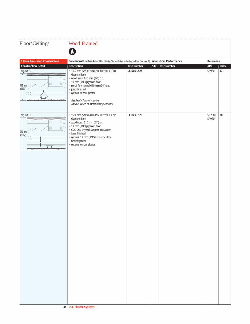
Wood FramedFloor/Ceilings
1 Hour Fire-rated Construction Dimensional Lumber (Refer to ULC/UL Design Directory listings for loading conditions. See page 4.) Acoustical Performance Reference
Construction Detail Description Test Number STC Test Number ARL Index
clg. wt. 3 • 15.9 mm (5/8�) GRAND PRIX FIRECODE C Core UL Des L528 SA920 37Gypsum Base
– wood truss, 610 mm (24�) o.c.– 19 mm (3/4�) plywood floor– metal fur channel 610 mm (24�) o.c.– joints finished• optional veneer plaster
Resilient Channel may be used in place of metal furring channel
clg. wt. 3 • 15.9 mm (5/8�) GRAND PRIX FIRECODE C Core UL Des L529 SC2000 38Gypsum Base SA920
– wood truss, 610 mm (24�) o.c.– 19 mm (3/4�) plywood floor• CGC DGL Drywall Suspension System– joints finished• optional 19 mm (3/4�) LEVELROCK Floor
Underlayment • optional veneer plaster
530 mm(207⁄8")
362 mm(141⁄4")
32 CGC Plaster Systems
Performance Selector
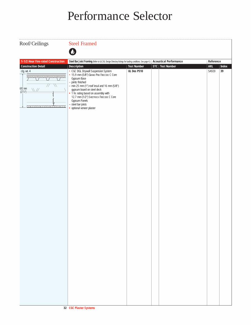
Steel FramedRoof/Ceilings
1-1/2 Hour Fire-rated Construction Steel Bar Joist Framing (Refer to ULC/UL Design Directory listings for loading conditions. See page 4.) Acoustical Performance Reference
Construction Detail Description Test Number STC Test Number ARL Index
clg. wt. 4 • CGC DGL Drywall Suspension System UL Des P510 SA920 39• 15.9 mm (5/8�) GRAND PRIX FIRECODE C Core
Gypsum Base – joints finished– min 25 mm (1�) roof insul and 16 mm (5/8�)
gypsum board on steel deck• 1 hr. rating based on assembly with
12.7 mm (1/2�) SHEETROCK FIRECODE C Core Gypsum Panels
– steel bar joists• optional veneer plaster
692 mm(271⁄4")
33 CGC Plaster Systems
ColumnStructural Fireproofing
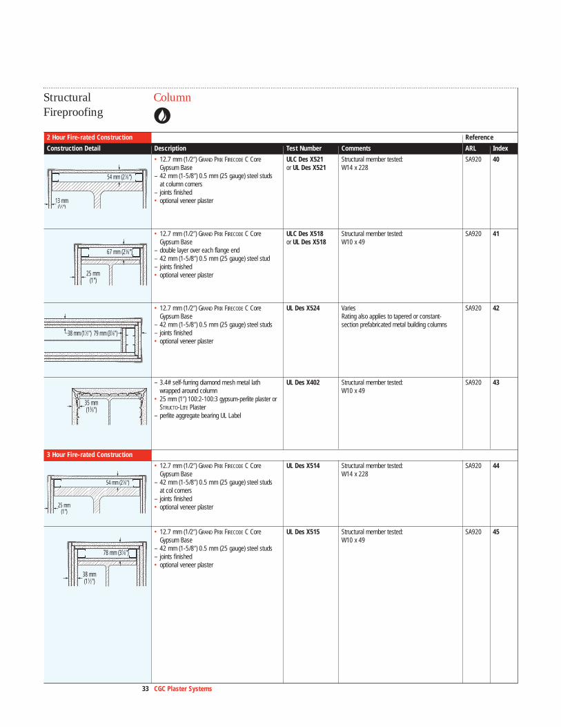
2 Hour Fire-rated Construction Reference
Construction Detail Description Test Number Comments ARL Index
• 12.7 mm (1/2�) GRAND PRIX FIRECODE C Core ULC Des X521 Structural member tested: SA920 40Gypsum Base or UL Des X521 W14 x 228
– 42 mm (1-5/8�) 0.5 mm (25 gauge) steel studs at column corners
– joints finished• optional veneer plaster
• 12.7 mm (1/2�) GRAND PRIX FIRECODE C Core ULC Des X518 Structural member tested: SA920 41Gypsum Base or UL Des X518 W10 x 49
– double layer over each flange end– 42 mm (1-5/8�) 0.5 mm (25 gauge) steel stud – joints finished• optional veneer plaster
• 12.7 mm (1/2�) GRAND PRIX FIRECODE C Core UL Des X524 Varies SA920 42Gypsum Base Rating also applies to tapered or constant-
– 42 mm (1-5/8�) 0.5 mm (25 gauge) steel studs section prefabricated metal building columns– joints finished• optional veneer plaster
– 3.4# self-furring diamond mesh metal lath UL Des X402 Structural member tested: SA920 43wrapped around column W10 x 49
• 25 mm (1�) 100:2-100:3 gypsum-perlite plaster or STRUCTO-LITE Plaster
– perlite aggregate bearing UL Label
3 Hour Fire-rated Construction•
• 12.7 mm (1/2�) GRAND PRIX FIRECODE C Core UL Des X514 Structural member tested: SA920 44Gypsum Base W14 x 228
– 42 mm (1-5/8�) 0.5 mm (25 gauge) steel studs at col corners
– joints finished• optional veneer plaster
• 12.7 mm (1/2�) GRAND PRIX FIRECODE C Core UL Des X515 Structural member tested: SA920 45Gypsum Base W10 x 49
– 42 mm (1-5/8�) 0.5 mm (25 gauge) steel studs – joints finished• optional veneer plaster
38 mm(11⁄2")
78 mm (31⁄8")
25 mm(1")
54 mm (21⁄8")
35 mm(13⁄8")
38 mm (11⁄2") 79 mm (31⁄8")
67 mm (25⁄8")
25 mm(1")
13 mm(1⁄2")
54 mm (21⁄8")
34 CGC Plaster Systems
Performance Selector
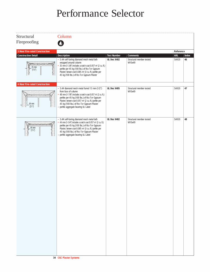
ColumnStructural Fireproofing
3 Hour Fire-rated Construction Reference
Construction Detail Description Test Number Comments ARL Index
– 3.4# self-furring diamond mesh metal lath UL Des X402 Structural member tested: SA920 46wrapped around column W10x49
• 35 mm (1-3/8�) includes scratch coat 0.057 m3 (2 cu. ft.) perlite per 45 kg (100 lbs.) of RED TOP Gypsum Plaster; brown coat 0.085 m3 (3 cu. ft.) perlite per 45 kg (100 lbs.) of RED TOP Gypsum Plaster
4 Hour Fire-rated Construction
– 3.4# diamond mesh metal furred 13 mm (1/2�) UL Des X405 Structural member tested: SA920 47from face of column W10x49
• 48 mm (1-7/8�) includes scratch coat 0.057 m3 (2 cu. ft.) perlite per 45 kg (100 lbs.) of RED TOP Gypsum Plaster; brown coat 0.057 m3 (2 cu. ft.) perlite per 45 kg (100 lbs.) of RED TOP Gypsum Plaster
– perlite aggregate bearing UL Label
– 3.4# self-furring diamond mesh metal lath UL Des X402 Structural member tested: SA920 48• 44 mm (1-3/4�) includes scratch coat 0.057 m3 (2 cu. ft.) W10x49
perlite per 45 kg (100 lbs.) of RED TOP Gypsum Plaster; brown coat 0.085 m3 (3 cu. ft.) perlite per 45 kg (100 lbs.) of RED TOP Gypsum Plaster
– perlite aggregate bearing UL Label
44 mm(13⁄4")
64 mm(21⁄2")
35 mm(13⁄8")
35 CGC Plaster Systems
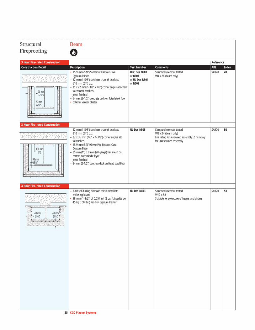
BeamStructural Fireproofing
3 Hour Fire-rated Construction Reference
Construction Detail Description Test Number Comments ARL Index
• 15.9 mm (5/8�) SHEETROCK FIRECODE Core ULC Des O503 Structural member tested: SA920 49Gypsum Panels or O504 W8 x 24 (beam only)
– 42 mm (1-5/8�) steel run channel brackets or UL Des N501610 mm (24�) o.c. or N502
– 35 x 22 mm (1-3/8� x 7/8�) corner angles attached to channel brackets
– joints finished– 64 mm (2-1/2�) concrete deck on fluted steel floor• optional veneer plaster
3 Hour Fire-rated Construction
– 42 mm (1-5/8�) steel run channel brackets UL Des N505 Structural member tested: SA920 50610 mm (24�) o.c. W8 x 24 (beam only)
– 22 x 35 mm (7/8� x 1-3/8�) corner angles att Fire rating for restrained assembly; 2 hr ratingto brackets for unrestrained assembly
• 15.9 mm (5/8�) GRAND PRIX FIRECODE Core Gypsum Base
– 25 mm (1�) 0.8 mm (20 gauge) hex mesh on bottom over middle layer
– joints finished– 64 mm (2-1/2�) concrete deck on fluted steel floor
4 Hour Fire-rated Construction
– 3.4# self-furring diamond mesh metal lath UL Des D403 Structural member tested: SA920 51enclosing beam W12 x 58
• 38 mm (1-1/2�) of 0.057 m3 (2 cu. ft.) perlite per Suitable for protection of beams and girders45 kg (100 lbs.) RED TOP Gypsum Plaster
48 mm(17⁄8")
48 mm(17⁄8")
100 mm(4")
98 mm(37⁄8")
70 mm(23⁄4")
70 mm(23⁄4")
36 CGC Plaster Systems
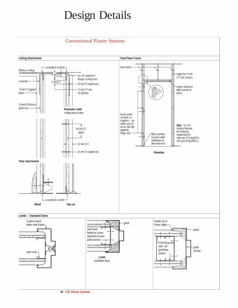
Design Details
Conventional Plaster Systems
Ceiling Attachment Steel Door Frame
Jambs – Standard Doors
cornerite
finished ceiling
Floor attachment
Perimeter reliefceiling intersection
Top setWood
no. 66 expanded flange casing bead
13 mm (1/2")
13 mm (1/2")
13 mm (1/2") min. for deflection
13 mm (1/2") gypsum plaster
10 mm (3/8") ROCKLATH plaster base
22 mm (7/8")
25 mm (1") drywall screw
50 mm (2") approx.
25 mm (1") drywall screw
acoustical sealant
acoustical sealant
steel studs
locate jambanchors asrequired – onstrike side tooccur directlyoppositehinge side
runner fastened with screws tostuds
floor anchorssecured withminimum of two fasteners
Note: See CGCtechnical literature for reinforcing requirements of doors over 22.5 kg (50 lb.)and up to 90 kg (200 lb.)
Elevation
cripple stud 13 mm (1/2") min. clearance
3-piece knock down steel frame
steel stud
grout
trowel cut atframe edges
jamb anchor
0.8 mm (20 ga.) steelstuds– seegood designpractices
grout
Jamb(standard door)
steel studbolted or screw attached to eachjamb anchor
37 CGC Plaster Systems
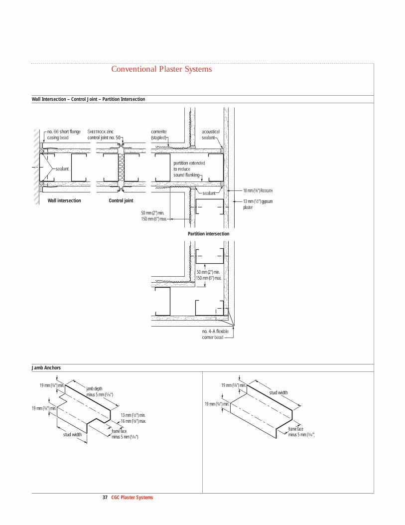
Wall Intersection – Control Joint – Partition Intersection
Jamb Anchors
Wall intersection Control joint
Partition intersection
sealant
sealant
SHEETROCK zinccontrol joint no. 50
no. 66 short flangecasing bead
cornerite(stapled)
partition extendedto reducesound flanking
no. 4-A flexible corner bead
acoustical sealant
10 mm (3/8") ROCKLATH
13 mm (1/2") gypsum plaster
50 mm (2") min. 150 mm (6") max.
50 mm (2") min. 150 mm (6") max.
stud width
13 mm (1/2") min. 16 mm (5/8") max.
19 mm (3/4") min.jamb depth minus 5 mm (3/16")
frame face minus 5 mm (3/16")
19 mm (3/4") min.
stud width
19 mm (3/4") min.
frame face minus 5 mm (3/16")
19 mm (3/4") min.
Conventional Plaster Systems
38 CGC Plaster Systems
Design Details
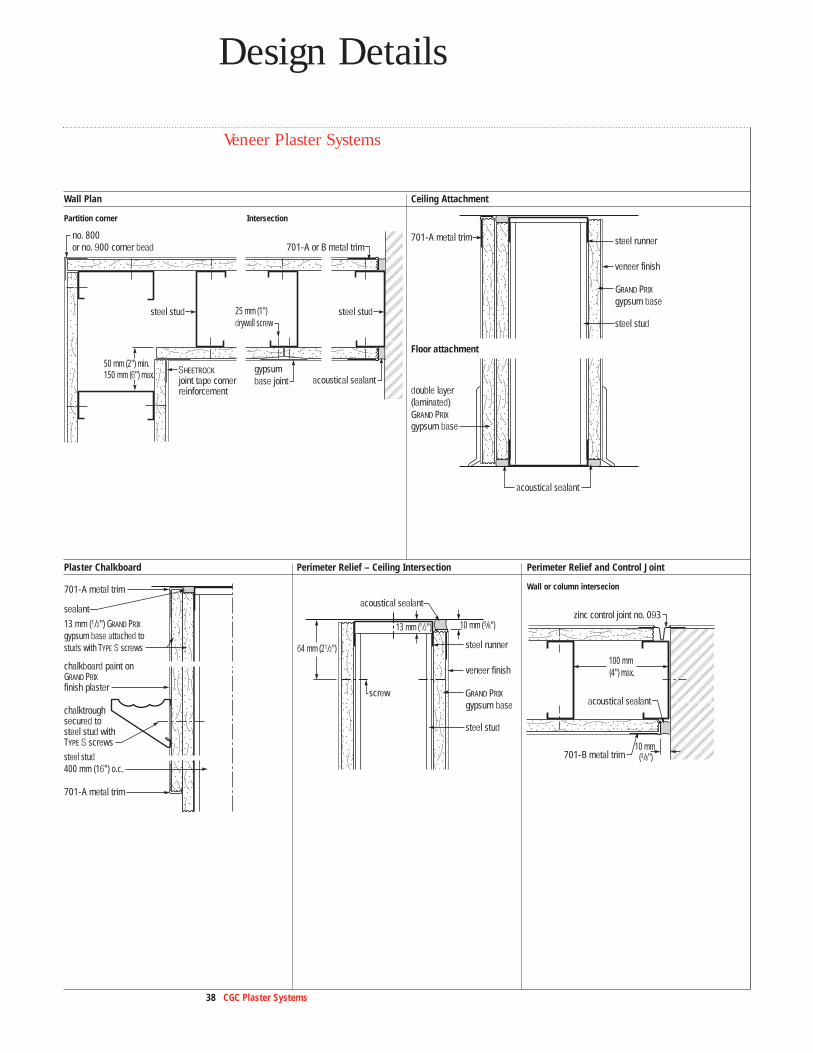
Veneer Plaster Systems
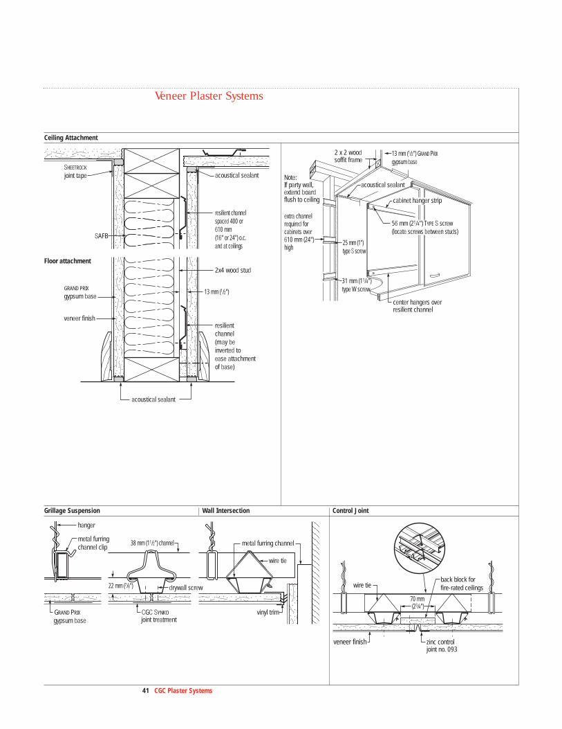
Wall Plan Ceiling Attachment
Plaster Chalkboard Perimeter Relief – Ceiling Intersection Perimeter Relief and Control Joint
acoustical sealant
double layer(laminated)
gypsum base
701-A metal trim
steel stud
steel runner
GRAND PRIX
GRAND PRIX
gypsum base
veneer finish
Floor attachment
701-A metal trim
701-A metal trim
chalktroughsecured to steel stud with TYPE S screws
chalkboard paint onGRAND PRIX finish plaster
sealant
13 mm (1/2") GRAND PRIX gypsum base attached to studs with TYPE S screws
steel stud 400 mm (16") o.c.
acoustical sealant
screw
steel stud
steel runner
GRAND PRIX
gypsum base
veneer finish
13 mm (1/2") 10 mm (3/8")
64 mm (21/2")
701-B metal trim
zinc control joint no. 093
acoustical sealant
10 mm (3/8")
100 mm (4") max.
acoustical sealantgypsum base joint
no. 800or no. 900 corner bead 701-A or B metal trim
steel stud steel stud
SHEETROCK joint tape corner reinforcement
25 mm (1") drywall screw
50 mm (2") min. 150 mm (6") max.
Partition corner Intersection
Wall or column intersecion
39 CGC Plaster Systems
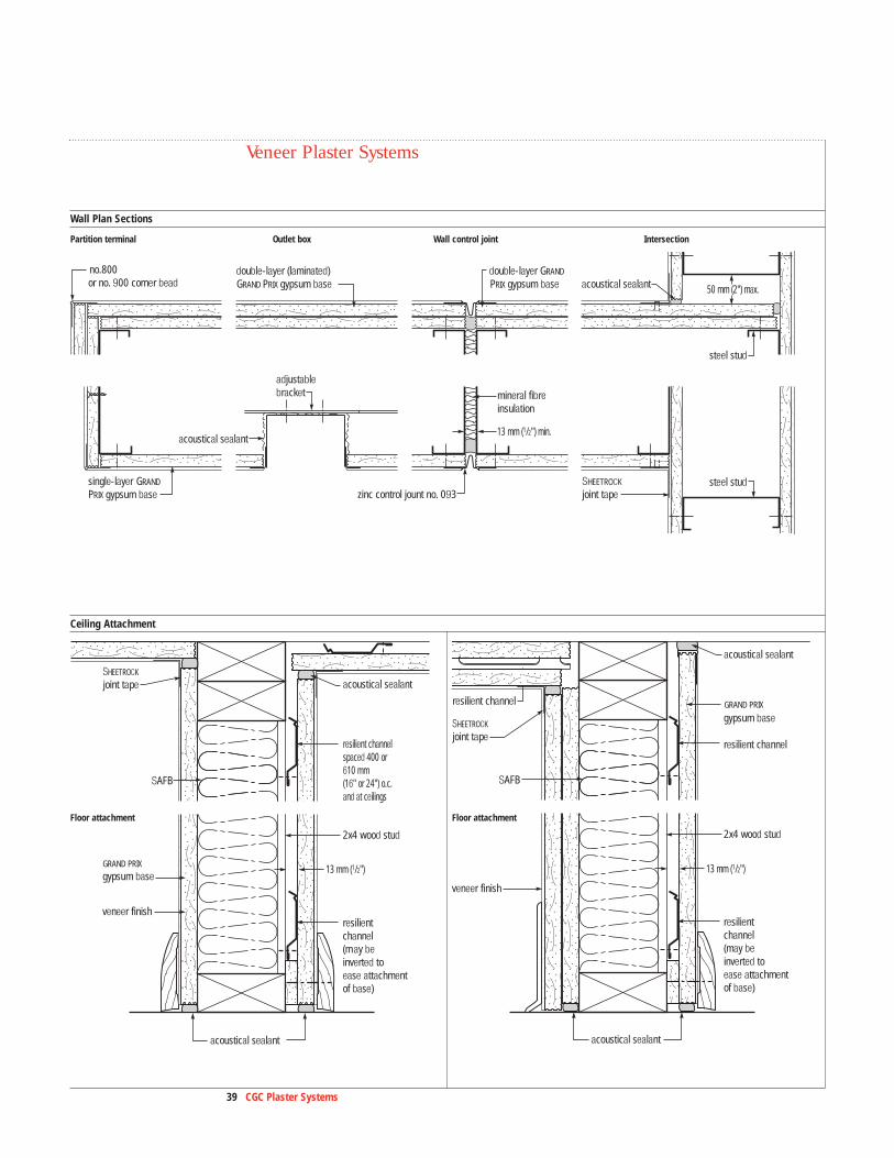
Wall Plan Sections
Ceiling Attachment
adjustablebracket
no.800 or no. 900 corner bead
zinc control jount no. 093SHEETROCK
joint tape
mineral fibreinsulation
steel stud
steel studsingle-layer GRAND
PRIX gypsum base
PRIX gypsum basedouble-layer (laminated) GRAND PRIX gypsum base
double-layer GRAND
acoustical sealant
acoustical sealant
13 mm (1/2") min.
50 mm (2") max.
acoustical sealant
acoustical sealant
SHEETROCK
joint tape
resilient channel (may be inverted to ease attachment of base)
Floor attachment
GRAND PRIX
gypsum base
veneer finish
SAFB
2x4 wood stud
13 mm (1/2")
resilient channel spaced 400 or 610 mm (16" or 24") o.c.and at ceilings
resilient channel
resilient channel
acoustical sealant
acoustical sealant
SHEETROCK
joint tape
resilient channel (may be inverted to ease attachment of base)
Floor attachment
gypsum base
veneer finish
SAFB
2x4 wood stud
13 mm (1/2")
GRAND PRIX
Partition terminal Outlet box Wall control joint Intersection
Floor attachment Floor attachment
Veneer Plaster Systems
40 CGC Plaster Systems
Design Details
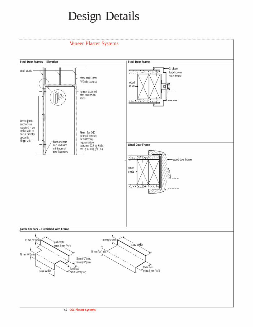
Veneer Plaster Systems
Steel Door Frames – Elevation Steel Door Frame
Jamb Anchors – Furnished with Frame
steel studs
locate jambanchors asrequired – onstrike side tooccur directlyoppositehinge side
runner fastened with screws tostuds
floor anchorssecured withminimum of two fasteners
Note: See CGCtechnical literature for reinforcing requirements of doors over 22.5 kg (50 lb.)and up to 90 kg (200 lb.)
cripple stud 13 mm (1/2") min. clearance
stud width
13 mm (1/2") min. 16 mm (5/8") max.
19 mm (3/4") min.jamb depth minus 5 mm (3/16")
frame face minus 5 mm (3/16")
19 mm (3/4") min.
stud width
19 mm (3/4") min.
frame face minus 5 mm (3/16")
19 mm (3/4") min.
woodstuds
3-pieceknockdownsteel frame
woodstuds
wood door frame
Wood Door Frame
41 CGC Plaster Systems
Ceiling Attachment
Grillage Suspension Wall Intersection Control Joint
CGC SYNKOjoint treatment
GRAND PRIX
gypsum base
drywall screw
hanger
metal furring channel clip
metal furring channel
vinyl trim
wire tie
38 mm (11/2") channel
22 mm (7/8")
zinc control joint no. 093
wire tie
veneer finish
back block for fire-rated ceilings
70 mm (23/4")
acoustical sealant
acoustical sealant
SHEETROCK
joint tape
resilient channel (may be inverted to ease attachment of base)
Floor attachment
GRAND PRIX
gypsum base
veneer finish
SAFB
2x4 wood stud
13 mm (1/2")
resilient channel spaced 400 or 610 mm (16" or 24") o.c.and at ceilings
Note:If party wall,extend boardflush to ceiling
center hangers over resilient channel
2 x 2 woodsoffit frame
acoustical sealant
cabinet hanger strip
13 mm (1/2") GRAND PRIX gypsum base
31 mm (11/4") type W screw
56 mm (21/4") TYPE S screw (locate screws between studs)
25 mm (1") type S screw
extra channel required for cabinets over610 mm (24") high
Veneer Plaster Systems
42 CGC Plaster Systems
Design Details
Veneer Plaster Systems
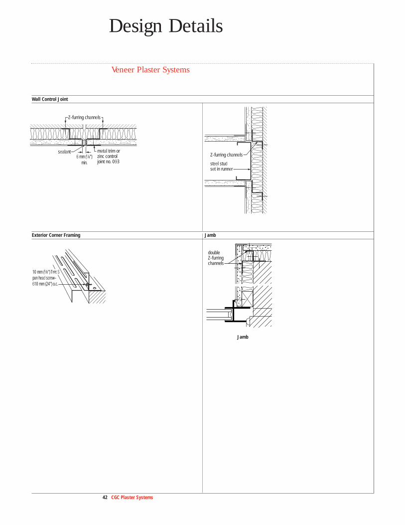
Wall Control Joint
Exterior Corner Framing Jamb
double Z-furringchannels
Jamb
Z-furring channels
sealant metal trim or zinc controljoint no. 093
6 mm (1/4")min. steel stud
set in runner
Z-furring channels
10 mm (3/8") TYPE S pan head screw– 610 mm (24") o.c.
43 CGC Plaster Systems
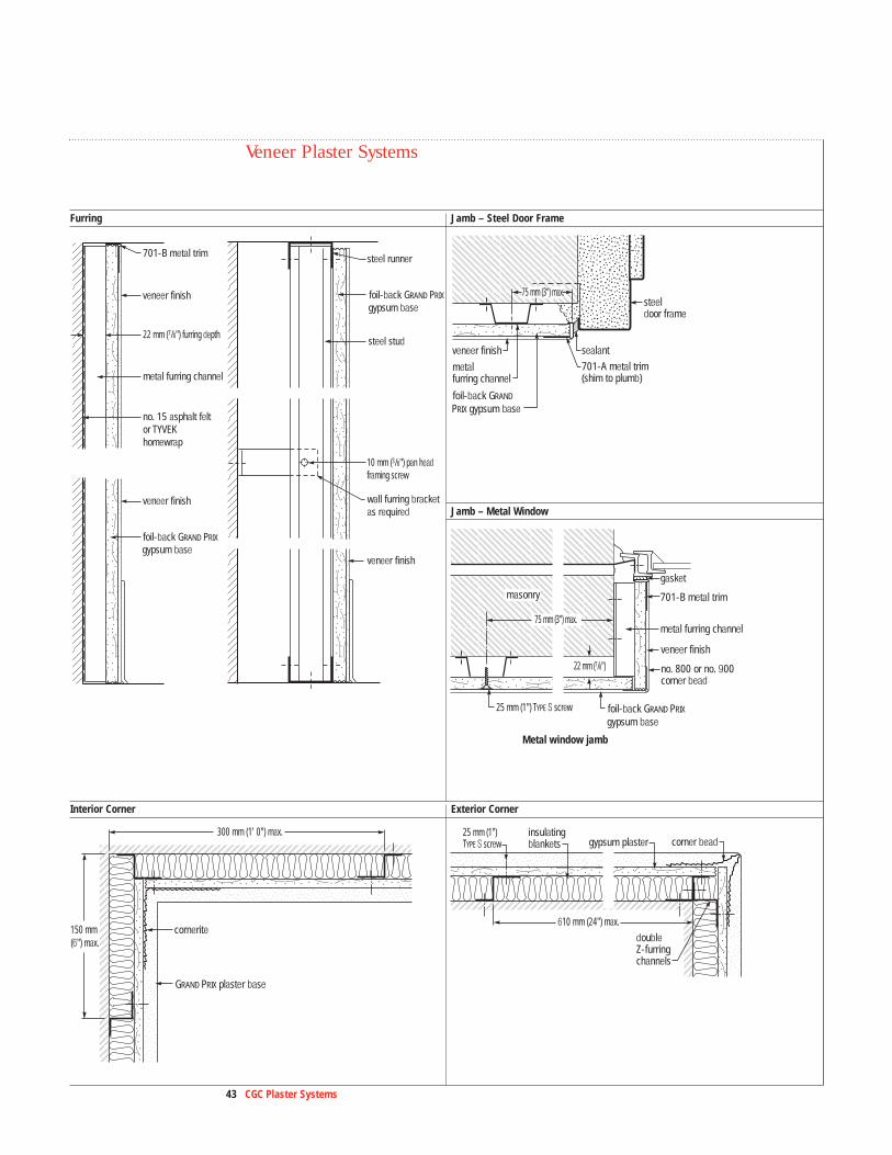
Furring Jamb – Steel Door Frame
Interior Corner Exterior Corner
veneer finish
veneer finish
foil-back GRAND PRIX
gypsum base
701-B metal trim
metal furring channel
no. 15 asphalt feltor TYVEK homewrap
22 mm (7/8") furring depth
steel runner
steel stud
veneer finish
wall furring bracketas required
foil-back GRAND PRIX
gypsum base
10 mm (3/8") pan head framing screw
veneer finish
metalfurring channel
sealant
steel door frame
701-A metal trim(shim to plumb)
foil-back GRAND
PRIX gypsum base
75 mm (3") max.
veneer finish
gasket
Metal window jamb
701-B metal trim
no. 800 or no. 900corner bead
masonry
metal furring channel
25 mm (1") TYPE S screw
75 mm (3") max.
22 mm (7/8")
foil-back GRAND PRIX
gypsum base
GRAND PRIX plaster base
cornerite
300 mm (1' 0") max.
150 mm (6") max.
insulating blankets gypsum plaster corner bead
double Z-furring channels
25 mm (1") TYPE S screw
610 mm (24") max.
Jamb – Metal Window
Veneer Plaster Systems
44 CGC Plaster Systems
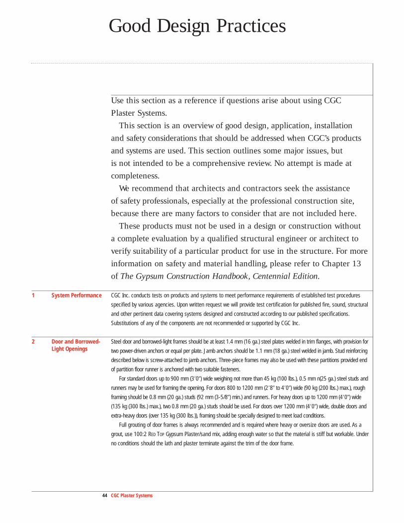
Good Design Practices
Use this section as a reference if questions arise about using CGC Plaster Systems.
This section is an overview of good design, application, installation and safety considerations that should be addressed when CGC’s productsand systems are used. This section outlines some major issues, but is not intended to be a comprehensive review. No attempt is made at completeness.
We recommend that architects and contractors seek the assistance of safety professionals, especially at the professional construction site,because there are many factors to consider that are not included here.
These products must not be used in a design or construction without a complete evaluation by a qualified structural engineer or architect to verify suitability of a particular product for use in the structure. For moreinformation on safety and material handling, please refer to Chapter 13 of The Gypsum Construction Handbook, Centennial Edition.
1 System Performance CGC Inc. conducts tests on products and systems to meet performance requirements of established test procedures
specified by various agencies. Upon written request we will provide test certification for published fire, sound, structural
and other pertinent data covering systems designed and constructed according to our published specifications.
Substitutions of any of the components are not recommended or supported by CGC Inc.
2 Door and Borrowed- Steel door and borrowed-light frames should be at least 1.4 mm (16 ga.) steel plates welded in trim flanges, with provision forLight Openings two power-driven anchors or equal per plate. Jamb anchors should be 1.1 mm (18 ga.) steel welded in jamb. Stud reinforcing
described below is screw-attached to jamb anchors. Three-piece frames may also be used with these partitions provided end
of partition floor runner is anchored with two suitable fasteners.
For standard doors up to 900 mm (3�0�) wide weighing not more than 45 kg (100 lbs.), 0.5 mm n(25 ga.) steel studs and
runners may be used for framing the opening. For doors 800 to 1200 mm (2�8� to 4�0�) wide (90 kg (200 lbs.) max.), rough
framing should be 0.8 mm (20 ga.) studs (92 mm (3-5/8�) min.) and runners. For heavy doors up to 1200 mm (4�0�) wide
(135 kg (300 lbs.) max.), two 0.8 mm (20 ga.) studs should be used. For doors over 1200 mm (4�0�) wide, double doors and
extra-heavy doors (over 135 kg (300 lbs.)), framing should be specially designed to meet load conditions.
Full grouting of door frames is always recommended and is required where heavy or oversize doors are used. As a
grout, use 100:2 RED TOP Gypsum Plaster/sand mix, adding enough water so that the material is stiff but workable. Under
no conditions should the lath and plaster terminate against the trim of the door frame.
45 CGC Plaster Systems
Spot grouting for standard doors and openings or where specified is recommended as a minimum to full grouting.
To spot grout, apply job-sanded RED TOP Gypsum Plaster, STRUCTO-LITE Gypsum Plaster or DURABOND Setting-Type Joint
Compound mixed in accordance with bag instructions to each jamb anchor, filling the inside face of the jamb at each
point. Immediately insert plaster base into the jamb and attach to framing. Do not terminate base against the trim.
Grouting of tube-type frames or exterior door frames is not recommended at any time, as grout is unable to dry
properly and may cause metal frames to rust.
3 Ceilings Spacing of hangers and channels is designed to support only the dead load. Heavy concentrated loads should be
independently supported. Lighting fixtures or troffers, air vents, and other equipment should be separately supported
from the ceiling grid or structure above; gypsum base will not support these items.
To prevent objectionable sag in new gypsum base ceilings, the weight of overlaid unsupported insulation should not
exceed 6.5 kg/m2 (1.3 psf) for 13 mm (1/2�) thick base with frame spacing 610 mm (24�) o.c.; 11.0 kg/m2 (2.2 psf) for
13 mm (1.2�) base on 400 mm (16�) o.c. framing and 16 mm (5/8�) base on 400 mm (24�) o.c. framing. Foil-back base or a
separate vapor retarder should be installed in all roofed ceilings if required by design, and the plenum or attic space vented
with a ratio of 1:300 (Net free area: Horizontal surface area).
4 Control Joints Compensation must be made for dimensional changes in wall and ceiling surfaces caused by changes in temperature
and humidity. Location of control joints is the responsibility of the design professional/architect.
Gypsum base assemblies should be isolated with control joints or by other means where: (a) partition or furring abuts a
structural element (except floor) or dissimilar wall or ceiling; (b) ceiling abuts a structural element, dissimilar wall, partition
or other vertical penetration; (c) construction changes within the plane of the partition or ceiling; (d) partition or furring run
exceeds 9 m (30�); (e) ceiling dimensions exceed 15 m (50�) in either direction with perimeter relief, 9 m (30�) without
relief; (f) expansion or control joints occur in the base exterior wall.
Ceiling height door frames may be used as control joints. Less-than-ceiling height frames should have control joints
extending to ceiling from both corners.
093 Zinc Control Joints, when properly insulated or backed by gypsum board, have been fire-endurance tested and
are certified for use in one- and two-hour fire-rated walls.
Refer to PM17, Preventing Cracks in Veneer and Conventional Plaster Systems, for complete information.
5 Penetrations Penetrations of the lath-and-plaster diaphragm such as borrowed lights, access panels and light troffers, require
additional reinforcement at corners to distribute concentrated stress if a control joint is not used.
6 Plaster/Metal Where a plaster surface is flush with metal, metal bucks, metal windows or metal base, the plaster should be trowel-Interface cut between the two materials.
7 Pipe and Conduit Additional chases can be provided in steel studs (except in fire-rated construction) by cutting round holes up to 3/4 of Chase stud width, spaced 300 mm (12�) apart.

Good Design Practices
46 CGC Plaster Systems
8 Ceramic Tile GRAND PRIX Gypsum Base is not recommended as a base for the adhesive application of ceramic tile and plastic-faced
panels. FIBEROCK AQUA-TOUGH Tile Backerboard or DUROCK Cement Board is recommended for this use. Double-layer panels
are required for resilient systems. Refer to SA934, Moisture-Resistant Assemblies, and SA927, Gypsum Panels and
Accessories.
9 Fixture Attachment Lightweight fixtures and trim should be installed with toggle bolts or hollow wall anchors inserted in the base, and,
preferably, also through the stud. Wood or metal mounting strips for cabinets and shelving should be bolted to stud
framing.
10 Zinc Alloy Recommended where corrosion due to high humidity or saline content of aggregate is possible. Metal lath,Accessories control joints and other metal accessories, including zinc-alloy accessories, should not be used with magnesium
oxychloride cement stuccos or portland cement stucco containing calcium chloride additives.
11 Joint Treatment For steel frame systems, SHEETROCK or DURABOND Setting-Type Joint Compound and SHEETROCK Joint Tape must be used
on all joints and internal corners and allowed to set and dry before veneer plaster application. See PM5, Veneer Plaster
Joint Reinforcement Systems, for complete information.
12 Decorating Plaster systems must be completely dry before decoration.
Do not specify polyvinyl acetate (PVA) primers for application to plaster finishes containing lime. In the presence of
moisture, these primers can cause bond loss with resultant paint delamination and job failure.
Caution should be used in selection and use of epoxy-based finish systems over lime putty/gauging plaster and
lime-containing finish plasters as these high-strength coating systems create a significant degree of surface stress at
the coating/plaster interface. Use of a penetrating primer/sealer is required to adequately enhance and fortify the
plaster surface when such finish coating systems are used. In all cases, the paint manufacturer should be consulted in
selection and final application procedures.
Veneer—Painting or further decoration of all plaster finishes is recommended and should be specified. However, in
many residential applications, DIAMOND Interior Finish provides a uniform white colour and may satisfy a job’s specific
acceptance specifications when textured and left undecorated. IMPERIAL Finish Plaster and DIAMOND Interior Finish
Plasters, if completely dry, may be painted the day after application with acrylic, latex or vinyl-breather-type paints.
Conventional—Gauged-lime putty and RED TOP Finish applied over conventional basecoat plasters must age 30 days
and be thoroughly dry and properly sealed before decorating. Quick-drying vinyl acrylic latex or alkali-resistant alkyd
primer-sealers are recommended.
13 Sound Control Sound tests are conducted under ideal laboratory conditions per ASTM procedures. Comparable field performance
depends on building design and careful attention to detailing and workmanship. Where these partitions are used for
sound control, seal the partition perimeter with 6 mm (1/4�) min. round bead of acoustical sealant. Seal around all
cutouts for lights, cabinets, pipes, ducts and electrical boxes. Back-to-back penetrations of the diaphragm, flanking
paths and door and borrowed-light openings should be avoided. Where sound isolation is the primary consideration, only
sand-aggregated basecoat plasters should be used.
47 CGC Plaster Systems
14 Shadowing and Temperature differentials on the interior surface of exterior walls may result in collection of airborne dirt on the colder Spotting surface areas. Consequently, accumulated dirt in the form of shadowing and spotting may occur at locations of fasteners
or framing where surface temperatures usually are lowest. This is a natural phenomenon which occurs through no fault
of the products.
Where temperature, humidity and soiling conditions are expected to cause objectionable shadowing and spotting,
one of the following alternatives should be considered:
A. The interior facing of GRAND PRIX Foil-Back Gypsum Base should be furred from the exterior wall studs using a base layer
of panels screw-attached to the studs and horizontally applied metal furring channels spaced 610 mm (24�) o.c.
B. On exterior masonry walls, install rigid or semi-rigid insulation between Z-Furring Channels affixed to interior side of
wall and finish with GRAND PRIX Foil-Back Gypsum Base.
C. For maximum resistance to shadowing and spotting, a separate free-standing wall construction is recommended using
studs that are independent of the exterior wall.
15 High-Rise Buildings Variable wind pressure can cause a structure to drift or sway. This can result in movement of the non-loadbearing
partitions, causing noise. CGC Inc. assumes no responsibility for the prevention, cause, or repair of these job-related
noises.
16 Note CGC Inc. reserves the right to make changes or improvements in the design of all catalogued items without notice and
without obligation to incorporate these changes or improvements in items already manufactured.
17 Specifications The following are minimum basic guides for preparation of job specifications. They are prepared for normal construction
and are not intended to cover every possible design or job condition. Specific product data sheets are available from
CGC Inc. for additional details and plaster specifications. Requests for these publications can be directed to the local
sales offices identified on the last page of this brochure.
18 Additional See SA100, Fire-Resistant Assemblies, for fire- and sound-rated systems; SA933, Aesthetic Assemblies, forInformation texturing specifications; SA934, Moisture-Resistant Assemblies; and SA927, Gypsum Panels and Accessories, for
information on gypsum panels; and for information on moisture-resistant panels and boards.

48 CGC Plaster Systems
Application Guide Specifications
This guide is provided to assist you in specification of CGC Plaster Systems. If you haveadditional questions or would like more information regarding this or other CGC productsand systems, please contact CGC at 800 387.2690.
Part 1: General
1.1 Specify areas to receive this treatment.Scope
1.2 All materials described in this publication manufactured by or for CGC Inc. shall be installed in accordance with its Qualifications current printed directions.
Warning: Store all GRAND PRIX Gypsum Base, FIBEROCK Panels and DUROCK Cement Board flat. Panels are heavy and can
fall over, causing serious injury or death. Do not move unless authorized.
1.3 All materials, except water and sand, shall be delivered in their original unopened packages and stored in an enclosed Delivery and Storage shelter providing protection from damage and exposure to the elements. Damaged or deteriorated materials shall be of Materials
removed from the premises.
1.4 1. In cold weather, all glazing shall be completed and the building heated to a minimum of 13 °C (55 °F) before gypsumEnvironmental base and lath installation. Temperature of building shall be maintained in uniform range above 13 °C (55 °F) for an Conditions
adequate period prior to application of plaster, while plastering is being done, and until plaster is dry.
Heat shall be well distributed in all areas, with deflection or protective screens used to prevent concentrated or
uneven heat distribution on plaster near source.
2. Ventilation and air circulation shall be kept to a minimum level during veneer plastering until the plaster has set and
completely dried.
3. Ventilation shall be provided to properly dry conventional plaster during and subsequent to its application. In glazed
buildings, this shall be accomplished by keeping windows open sufficiently to provide air circulation; in enclosed areas
lacking normal ventilation, provisions must be made to mechanically remove moisture-laden air.
4. If glazed sashes are not in place and the building is subject to hot, dry winds or temperature differentials from day to night of
11 °C (20 °F) or more, openings shall be screened with cheesecloth or similar material.
1.5 Proper protection shall be provided during plastering for finished door and window frames and other designated areas Protection that do not receive a plaster finish.
1.6 1. With application over interior monolithic concrete, surface must first be treated with an application of CGC Plaster Basecoat Plaster Bonder.General Limitations
2. Basecoat surface must be serrated or broomed to roughen and open the surface to allow for proper suction and
to develop proper bond of the finish coat to the basecoat.
3. Gypsum plasters should not be used where they will come in contact with water or excessive moisture. May be applied
to exterior soffits protected from direct exposure to rain and moisture. Suitable drips and casings along the edges are
required.
4. Plaster application is not recommended over bituminous compounds or other waterproofing agents.
5. Interior surface of exterior masonry or monolithic concrete walls shall be furred and lathed prior to plastering.
49 CGC Plaster Systems
6. STRUCTO-LITE Gypsum Plaster or basecoat plasters containing job-mixed lightweight aggregate require a lime-gauging
finish plaster containing a fine aggregate to control surface cracking.
7. Lightweight basecoat plasters shall not be specified over metal lath when smooth trowel finish is required.
8. General practice dictates that there should be a lower sand-to-gypsum plaster ratio in the scratch coat than in the
brown coat.
1.7 1. Application thickness for veneer basecoat, veneer finishing, gauging-lime or factory-prepared gauging-lime finish Veneer Plaster plasters is 1.5 - 2.4 mm (1/16� - 3/32�).Systems
2. Rapid drying conditions, steel framing and certain framing situations on 610 mm (24�) o.c. require use of paper tape and Limitationssetting-type compound.
A. Substrates
1. Ceramic tile should not be attached directly to veneer base; plaster must be applied first.
2. Foil-backed base should not be used as a substrate for ceramic tile, or as the face layer in multilayer systems.
3. Masonry substrate must be clean, porous, with joints struck flush, and may need to be dampened to control excess
suction. A two-coat system is required over masonry.
4. Monolithic concrete must be clean, fully cured, and free of oils, efflorescence and other foreign materials. CGC Plaster
Bonder must be applied prior to plaster application.
5. Sunfaded GRAND PRIX Gypsum Base should be treated with CGC Plaster Bonder before plaster application when applying
DIAMOND Interior Finish Plaster.
B. Basecoats
May be applied directly to porous unit masonry or over cured monolithic concrete treated with CGC Plaster Bonder.
Once the basecoat is applied and has become firm, the surface shall be raked or broomed to provide a rough, open
surface necessary for proper suction and finish coat bond.
C. Veneer Finishes
1. Single coat veneer plaster finishes are not recommended for use over portland cement basecoats or unit masonry
construction.
2. Only job-sanded DIAMOND Interior Finish Plaster is recommended for electric heat cables. When job-sanded DIAMOND
Interior Finish Plaster is used for a radiant heat system, the cable-sheath operating temperatures must not exceed
52 °C (125 °F).
1.8 1. Lime gauging finishes are not recommended for smooth application over lightweight aggregate gypsum basecoat Finish Coat Plaster applied over metal lath. Only sand-float finishes are recommended over metal lath.General Limitations
2. Where the gypsum basecoat contains lightweight aggregate (perlite or vermiculite), the finish coat should be:
a) (RED TOP) factory-aggregated gauging plaster, or
b) RED TOP Gauging Plaster and lime with addition of 0.014 m3 (1/2 cu. ft.) of perlite fines per 45 kg (100 lbs.) gauging plaster, or
c) RED TOP Gauging Plaster and lime with addition of 22.5 kg (50 lb.) of No. 1 white silica sand per 45 kg (100 lbs.) gauging
plaster.
3. Gypsum and lime-based finishes, should not be used directly over a portland cement basecoat or over concrete block or
other masonry surfaces.
Application Guide Specifications
50 CGC Plaster Systems
4. Gauged-lime putty and RED TOP Finish applied over conventional basecoat plasters must age 30 days, be thoroughly
dry and properly sealed before decorating. Quick-drying vinyl acrylic latex or alkali-resistant alkyd paints and
primer-sealers are recommended.
5. Primers containing polyvinyl acetate (PVA) are not recommended and should not be specified for use with any plaster
finish with the exception of IMPERIAL Finish Plaster. PVA primers can cause bond loss with resultant paint delamination
and job failure when used over lime containing plasters. Strictly follow the specific product recommendations of paint
manufacturers for painting lime-gauging putty finishes.
1.9 1. Maximum frame spacing for 10 mm (3/8�) GRAND PRIX Plaster Base should not exceed 400 mm (16�) o.c.Gypsum Plaster 2. For general information on steel framing, consult SA100, Fire-Resistant Assemblies.Lath Limitations
3. Shall be used with gypsum plasters only. Lime-based plaster and portland cement plaster are incompatible with USG
ROCKLATH Plaster Base and shall not be specified.
4. Shall not be used in areas with sustained high relative humidity or where exposed to excessive moisture for extended
periods. (Galvanized metal lath and portland cement-lime plaster or a DUROCK Cement Board System is recommended for
wet areas. See SA700, Exterior System Substrates, and SA934, Moisture-Resistant Assemblies for more information.)
1.10 1. Metal lath products shall not be used with magnesium oxychloride cement stuccos or stuccos containing calciumMetal Lath General chloride additives.Limitations
2. In ceiling assemblies, a min. of 323 sq.mm (1/2 sq. in.) net free vent area is recommended 0.09 sq. m (per sq. ft.) of
horizontal surface in plenum or other space required.
1.11 1. These constructions should not be used where normally exposed to excessive moisture, humidity or temperature.Wood-Framed 2. TYPE S screws must be used for attachment of single-layer base to resilient channels.Veneer Plaster
3 Resilient channels must be attached to wood framing only with 38 mm (1-1/2�) Type W screws. Nails should not be used.Systems4. Resilient ceilings should not be installed beneath highly flexible floor joists.Limitations5. SHEETROCK Joint Tape and SHEETROCK Setting-Type Lightweight or DURABOND Setting-Type Joint Compound must be used to
treat all joints and internal angles when any of the following conditions exist: rapid drying conditions due to low humidity,
high temperature, and excessive evaporation, or 610 mm (24�) o.c. wood frame spacing and a single layer gypsum base
veneer system is specified (16 mm (5/8�) base with one-coat veneer finish and 13 or 16 mm (1/2� or 5/8�) base with
two-coat veneer finish). Allow joint treatment to set and dry thoroughly before plaster application.
6. To prevent fastener popping, GRAND PRIX Plaster Base should be attached with fasteners driven flush with the surface,
and not dimpled.
1.12 1. Non-loadbearing.Steel-Framed 2. These assemblies should not be used where exposed to excessive moisture, humidity or temperature.Veneer Plaster
3. Maximum frame spacing, and steel stud/runner structural properties limiting heights should not be exceeded. ConsultSystemsstud manufacturer’s tables and structural properties to determine final stud selection.Limitations
4. Select limiting heights and deflections for steel-framed veneer plaster systems as follows:
a) L/240 for veneer plaster systems
b) L/360 for conventional plaster systems and other brittle surface materials
51 CGC Plaster Systems
c) L/360 is recommended in specific critical areas such as for tall walls, walls with full or partial height tile,
and walls receiving eccentric loading (e.g., shelving on one side)
5. Joints must be finished using SHEETROCK Joint Tape and SHEETROCK or DURABOND Setting-Type Joint Compound. Joint
compound must be allowed to set before plaster application.
6. Control joints are required; refer to Good Design Practices, No. 4.
Part 2: Products
2.1 A. Steel StudsFraming, Furring, 0.5 mm (25 ga.) (42 mm (1-5/8�)), (64 mm (2-1/2�)), (92 mm (3-5/8�)), (100 mm (4�)), (150 mm (6�)), 0.76 mm (22 ga.) (64 mm (2-1/2�)),and Accessories
(92 mm (3-5/8�)), (100 mm (4�)), (150 mm (6�)), 0.8 mm (20 ga.) (64 mm (2-1/2�)), (92 mm (3-5/8�)), (100 mm (4�)), (150 mm (6�)).
B. Steel Runners
0.5 mm (25 ga.) (42 mm (1-5/8�)), (64 mm (2-1/2�)), (92 mm (3-5/8�)), (100 mm (4�)), (150 mm (6�)), 0.76 mm (22 ga.) (64 mm (2-1/2�)),
(92 mm (3-5/8�)), (100 mm (4�)), (150 mm (6�)), 0.8 mm (20 ga.) (64 mm (2-1/2�)), (92 mm (3-5/8�)), (100 mm (4�)), (150 mm (6�)).
C. Lathing Channels
Cold-Rolled Channels (19 mm (3/4�), 38 mm (1-1/2�), 50 mm (2�)) (ptd, galv).
D. Furring Channels
Metal Furring Channels (DWC-25) (DWC-20) Z-Furring Channels (25 mm (1�), (38 mm 1-1/2�), (50 mm 2�), (75 mm 3�)).
E. Resilient Channels
Resilient Channel.
F. Metal Angles
Galvanized Metal Angles (35 x 22 mm (1-3/8� x 7/8�)) (64 x 64 mm (2-1/2� x 2-1/2�)).
2.2 A. GRAND PRIX Gypsum Base Veneer Plaster Base (13 mm (1/2�)) (16 mm (5/8�)) (19 mm (3/4�)) thick, 1200 mm (48�) wide, square edge, (Regular) (FIRECODE) (FIRECODE C) (Abuse
Resistant) (ULTRACODE Core), (Foil-Back).
Note: Specify only with veneer plaster, No. 800 or No. 900 Corner Bead and IMPERIAL Joint Reinforcement Tape (Type P)
(TYPE S) or SHEETROCK Joint Tape and SHEETROCK or DURABOND Setting-Type Joint Compound.
B. DUROCK Cement Board
(13 mm (1/2�)) (16 mm (5/8�)) thick, 1200 mm (48�) wide.
C. FIBEROCK Interior AQUA-TOUGH Panels
(13 mm (1/2�)) (16 mm (5/8�)) (16 mm (5/8�) VHI) thick, 1200 mm (48�) wide, tapered edge.
2.3 A. ScrewsPlastering and Trim Size—(10 mm (3/8�)) (11 mm (7/16�)) (13 mm (1/2�)) (25 mm (1�)) (31 mm (1-1/4�)) (38 mm (1-1/2�)) (42 mm (1-5/8�)) (50 mm (2�)) Accessories—Veneer
(56 mm (2-1/4�)) (64 mm (2-1/2�)) (75 mm (3�)); style—(framing, TYPE S or S-12) (drywall, TYPE S) (self-drilling, TYPE S-12) (laminating, Type G) Plaster Systems(coarse thread, Type W) (DUROCK); head—(bugle) (pan) (trim) (pancake) (low-profile) (mod. truss head); coating—(reg) (corrosion-resistant Type III
coating or better per ASTM B117 (12 hours)
B. Corner Bead
No. 800 (for drywall and one-coat veneer plaster) No. 900 (for two-coat veneer plaster) Flexible Corner Bead (for
archways and curved designs).

Application Guide Specifications
52 CGC Plaster Systems
C. Trim
No. 701-A (J-Type) No. 701-B (L-Type) (for two-coat veneer plaster) No. 801-A,
No. 801-B (for one-coat veneer plaster).
D. Zinc Control Joint
No. 093 Control Joint.
E. Joint Reinforcement
SHEETROCK Joint Tape, SHEETROCK or DURABOND Setting-Type Joint Compound (for use over steel framing and when rapid drying
conditions exist) _______ Veneer Plaster (specify from product descriptions) and (50 mm (2�)) (64 mm (2-1/2�)) IMPERIAL
Tape (Type P) (TYPE S) (to embed tape over wood framing).
F. Clip
Metal Furring Channel Clip.
G. Furring Brackets
Adjustable Wall Furring Brackets.
H. Wire
Hanger Wire (3.3 mm (8 ga.)) Tie Wire (1.1 mm (18 ga.)).
I. Caulking
Acoustical Sealant.
J. Laminating Adhesive
SHEETROCK DURABOND Setting-Type Joint Compound.
K. CGC Plaster Bonder
L. CGC ACRI-ADD™ 100% Acrylic Add-Mix Fortifier
2.4 A. Veneer Plaster Basecoat Plastering Material— IMPERIAL Basecoat Plaster, DIAMOND Veneer Basecoat Plaster.Veneer Plaster
B. Veneer Plaster—Prepared FinishSystemsIMPERIAL Finish Plaster, DIAMOND Interior Finish Plaster, RED TOP Finish.
C. Finish Lime
SNOWDRIFT (type S); RED TOP, (type N).
D. Gauging Plaster
RED TOP Gauging.
E. Grout
Job-sanded RED TOP Gypsum Plaster, STRUCTO-LITE Gypsum Plaster, DURABOND Setting-Type Joint Compound.
F. Water
Potable without impurities that affect the setting of gypsum.
G. Special Plasters
CGC Moulding Plaster, White HYDROCAL Gypsum Cement.
2.5 A. Veneer Plaster BasecoatMixes—Veneer Plaster __________shall be mixed in accordance with water proportions identified on bag. Mix for 2 to 5 minutes with a cage-type
paddle mixer using a 900-1000 rpm 13 mm (1/2�) drill.
53 CGC Plaster Systems
B. Veneer Plaster—Prepared Finish
Add all but 1 to 2 litres of the required water to a non-plastic mixing container. Mix for 1 to 2 minutes, add up to 1 to 2 litres of
retained water and then mix for 1 to 2 minutes more. Mix with a cage-type paddle mixer using a 900-1000 rpm 13 mm (1/2�)
drill. (See PM19.)
C. Conventional Plasters over a Veneer Basecoat
1. SNOWDRIFT Lime: Shall be machine-mixed for immediate use with approx. 20-24 litres water per 22.5 kg (50 lb.) bag.
2. RED TOP Lime: Shall be box-soaked or machine-mixed using approx. 24 litres water per 22.5 kg (50 lb.) bag, and allowed to
soak for 16 hours.
3. Finish Plaster: Shall be mixed in proportion by dry weight of ______ parts of gauging to ______ parts of lime (specify
from coverage data), according to applicable bag directions. Over lightweight aggregate basecoats (such as STRUCTO-LITE
Gypsum Plaster) add 0.014 m3 (1/2 cu. ft.) of perlite fines or 22.5 kg (50 lbs.) of No. 1 silica sand per 45 kg (100 lb.) of
gauging plaster or use mill-aggregated “quality” gauging plaster.
2.6 A. GRAND PRIX Plaster BaseConventional Plaster (12 x 1220 x 2440 mm (1/2� x 48� x 96�)).Lathing Materials
B. Metal Lath
Diamond Mesh Lath (0.94, 1.34, 1.82 kg/m2 (1.75, 2.5, 3.4)) lb., (ptd, galv); Self-Furring Diamond Mesh Lath (1.34, 1.82 kg/m2
(2.5, 3.4)) lb., (ptd, galv), (Paper-Backed—Grade B or Grade D), Flat Riblath (1.34, 1.82 kg/m2 (2.75, 3.4)) lb., (ptd, galv), 10 mm (3/8�)
Riblath (1.82 kg/m2 (3.4)) lb., (ptd, galv).
2.7 A. ScrewsLathing Accessories— Select from listing in 2.3 A (above).Conventional
B. Corner BeadPlaster Systems1-A Expanded, Double-X.
C. Casing Beads
Casing Bead #66 Expanded Flange (6 mm, 10 mm, 13 mm, 16 mm, 19 mm, 22 mm, 25 mm, 31 mm (1/4�, 3/8�, 1/2�, 5/8�, 3/4�, 7/8�, 1�,
1-1/4�)) (galv, zinc), Casing Bead #66 Short Flange (6 mm, 10 mm, 13 mm, 16 mm, 19 mm, 22 mm (1/4�, 3/8�, 1/2�, 3/4�, 7/8�)) (galv, zinc).
D. Zinc Control Joint
093 Zinc Control Joint (#50, #75, #100) (zinc), Double-V Expansion Joint (13 mm, 19 mm (1/2�, 3/4�)) (galv, zinc).
E. Reinforcement
Cornerite, Striplath.
F. Wire
Hanger Wire (3.3 mm (8 ga.)), Tie Wire (1.1 mm (18 ga.)).
2.8 A. Basecoat Plaster—ConventionalPlastering Material— RED TOP Gypsum Plaster, STRUCTO-LITE Gypsum Plaster.Conventional Plaster
B. AggregateSystemsSand, perlite (meeting ASTM C35) sand for float finishes shall be graded (white) silica sand passing a (30 mesh)
(20 mesh) screen.
C. Finish Lime
SNOWDRIFT (type S); RED TOP (type N).

Application Guide Specifications
54 CGC Plaster Systems
D. Gauging Plaster
RED TOP Gauging.
E. Grout
RED TOP Gypsum Plaster, job-sanded, STRUCTO-LITE Gypsum Plaster, SHEETROCK DURABOND Setting-Type Joint Compound.
F. Water
Potable without impurities that affect the setting of gypsum.
G. Special Plasters
CGC Moulding Plaster, White HYDROCAL Gypsum Cement.
H. Portland Cement
Type 1 or 2, per ASTM C926.
2.9 A. Basecoat Plaster—ConventionalMixes— Basecoat plaster and aggregate shall be mixed in proportions of ______ (specify from technical data).Conventional Plaster
B. SNOWDRIFT Lime
Shall be machine-mixed for immediate use with approx. 20-24 litres water per 22.5 kg (50 lb.) bag.
C. RED TOP Lime
Shall be box-soaked or machine-mixed using approx. 24 litres water per 22.5 kg (50 lb.) bag, and allowed to soak for 16 hours.
D. Finish Plaster
Shall be mixed in proportion by dry weight of ______ parts of gauging to ______ parts of lime (specify from coverage
data), according to applicable bag directions. Over lightweight aggregate basecoats (such as STRUCTO-LITE Gypsum
Plaster) add 0.014 m3 (1/2 cu. ft.) of perlite fines or (22.5 kg (50 lbs.) of silica sand to meet ASTM C35 per 45 kg
(100 lb.)) of gauging plaster or use mill-aggregated “quality” gauging plaster.
E. Portland Cement
Mix TYPE S lime (MORTASEAL™ Mason’s Lime) or Type SA lime (BONDCRETE® Lime per ASTM C207) with portland cement
and sand according to ASTM C926, Type L mortar; suggested portland cement to lime to sand ratios by volume.
Basecoat: Scratch coat—1:1:8; brown coat—1:1:10.
Part 3: Execution
3.1 A. Partition Framing InstallationSteel Framing and Attach steel runners at floor and ceiling to structural elements with suitable fasteners located 50 mm (2�) from each end and Furring Installation
spaced 610 mm (24�) o.c., or to suspended ceilings with toggle or hollow wall anchors spaced 400 mm (16�) o.c.
Position steel studs vertically, engaging both floor and ceiling runners, and spaced max. (400 mm (16�)) (610 mm (24�)) o.c.
When necessary, splice studs with 200 mm (8�) nested lap and one positive attachment per stud flange. Place studs in direct
contact with door frame jambs, abutting partitions, partition corners and existing construction elements. Where studs are
attached to exterior walls and possibility of water penetration through walls exists, install asphalt felt strips between studs and
wall surfaces.
Anchor all studs adjacent to door and window frames, partition intersections, corners and free-standing furring to
ceiling and floor runner flanges with metal lock fastener tool or screws. Securely anchor studs to jamb and head anchors
55 CGC Plaster Systems
of door or borrowed-light frames by bolt or screw attachment. Over metal door and borrowed-light frames, place a
cut-to-length section of runner, with a web-flange bend at each end, and secure to strut-studs with two screws in
each bent web. Position a cut-to-length stud (extending to ceiling runner) at vertical plaster base joints over door
header. When attaching studs to steel grid system, structural adequacy of grid to support end reaction of wall must
be determined.
B. Chase Wall Framing Installation
Align two parallel rows of floor and ceiling runners spaced apart as detailed. Attach to concrete slabs with concrete stub nails
or power-driven anchors 610 mm (24�) o.c., to suspended ceilings with toggle bolts or hollow wall anchors 400 mm (16�) o.c.,
or to wood framing with suitable fasteners 610 mm (24�) o.c.
Position steel studs vertically in runners (400 mm (16�)) (610 mm (24�)) o.c., with flanges in the same direction, and
with studs on opposite sides of chase directly across from each other. Anchor all studs adjacent to door and window
frames, partition intersections and corners to floor and ceiling runner flanges with metal lock fastener tool or screws.
Cut cross bracing made from gypsum base 300 mm (12�) high by wall width. Place between rows of studs. Space braces
1200 mm (48�) o.c. vertically and attach to stud webs with six TYPE S screws per brace. If larger braces are used, space
screws 200 mm (8�) o.c. max. on each side. Attach single-layer or base-layer gypsum base with (25 mm (1�)) TYPE S screws
spaced 300 mm (12�) o.c. in field and 200 mm (8�) o.c. staggered at joints.
Bracing of 64 mm (2-1/2�) steel studs may be used in place of gypsum braces. Anchor web at each end of steel brace
with two pan head framing screws. When chase wall studs are not opposite, install steel stud cross braces 610 mm (24�) o.c.
horizontally and securely anchor each end to a continuous horizontal 64 mm (2-1/2�) runner screw-attached to chase wall
studs within the cavity.
C. Ceiling Grillage Installation
Space 3.3 mm (8 ga.) hanger wires 1200 mm (48�) o.c. along carrying channels and within 150 mm (6�) of ends of carrying
channel runs. In concrete, anchor hangers by attachment to reinforcing steel, by loops embedded at least 50 mm (2�) or by
approved inserts. For steel construction, wrap hanger around or through beams or joists.
Install 38 mm (1-1/2�) carrying channels 1200 mm (48�) o.c., and within 150 mm (6�) of walls. Position channels for proper ceiling height,
level and secure with hanger wire saddle-tied along channel. Provide 25 mm (1�) clearance between runners and abutting walls and partitions.
At channel splices, interlock flanges, overlap ends 300 mm (12�) and secure each end with double-strand 1.1 mm (18 ga.) tie wire.
Erect metal furring channels at right angles to 38 mm (1-1/2�) carrying channels or main support members. Space furring
(400 mm (16�)) (610 mm (24�)) o.c. and within 150 mm (6�) of walls. Provide 25 mm (1�) clearance between furring ends and abutting
walls and partitions. Secure furring to carrying channels with clips or saddle-tie to supports with double-strand 1.1 mm (18 ga.) tie
wire. At splices, nest furring channels at least 200 mm (8�) and wire-tie each end with double-strand 1.1 mm (18 ga.) tie wire.
At light troffers or any openings that interrupt the carrying or furring channels, install additional cross reinforcing to
restore lateral stability of grillage.
D. Resilient Channel Installation
Position resilient channel at right angle to steel studs, spaced 610 mm (24�) o.c., and attach to steel stud flanges with pan
head framing screws driven through holes in channel mounting flange and to wood framing with 31 mm (1-1/4�) wood
screws of Buildex Type W. Install channel with mounting flange down, except at floor to accommodate attachment. Locate
channels 50 mm (2�) from floor and within 150 mm (6�) of ceiling. Extend channels into all corners and attach to corner
framing. Cantilever channel ends no more than 150 mm (6�). Splice channel by nesting directly over framing member.
Reinforce with screws located at both ends of splice. Use of a filler strip at the base may reduce STC rating.
Where cabinets will be installed, attach resilient channels to studs at top and bottom cabinet hanger brackets. When
distance between hangers exceeds 610 mm (24�) o.c., install additional channel at midpoint between hangers.
Application Guide Specifications
56 CGC Plaster Systems
E. Z-Furring Channel Installation
Install insulation vertically and hold in place with Z-furring channels spaced 610 mm (24�) o.c. Except at exterior corners,
attach narrow flanges of furring channels to wall with concrete stub nails or power-drive fasteners spaced 610 mm (24�) o.c.
At exterior corners, attach wide flange of furring channel to wall with short flange extending beyond corner. On adjacent wall
surface, screw-attach short flange of furring channel to web of attached channel. Start from this furring channel with a
standard width insulation panel and continue in regular manner. At interior corners, space second channel no more than
300 mm (12�) from corner and cut insulation to fit. Hold mineral-fibre insulation in place until gypsum base is installed with
250 mm (10�) long staple field-fabricated from 1.1 mm (18 ga.) tie wire and inserted through slot in channel. Apply wood
blocking around window and door openings and as required for attachment of fixtures and furnishings.
F. Wall Furring Channel Attachment—Direct
Attach metal furring channels vertically, spaced (400 mm (16�)) (610 mm (24�)) o.c., to interior of masonry or concrete
surfaces with hammer-set or power-driven fasteners or concrete stub nails staggered 610 mm (24�) o.c. on opposite
flanges. Where furring channel is installed directly to exterior wall and a possibility of water penetration through walls exists,
install asphalt felt protection strip between furring channel and wall.
3.2 Install mineral fibre insulation after gypsum base is applied directly to the face of the studs on one side of the partition.Sound Attenuation Insert the 625 mm (25�) wide blanket in the stud cavity by bowing the blanket slightly. After inserting, make a vertical cut in theFire Blanket
blanket (about 25 mm (1�) deep) on a centerline between the studs. Butt ends of blankets closely together and fill all voids. ApplyInstallationgypsum base directly to studs or to resilient channels on the opposite side of the partition.
3.3 A. Ceiling InstallationVeneer Plaster Apply gypsum base of maximum practical length wherever possible on ceilings first with long dimension perpendicular Base Installation
to furring channels with blue face paper down. Position end joints over framing and stagger in adjacent rows.
Fit ends and edges closely, but not forced together. Fasten base to channels with 25 mm (1�) TYPE S screws spaced
300 mm (12�) o.c. in field of base and along abutting ends and edges.
For single-layer resilient ceiling system, apply GRAND PRIX Gypsum Base, ceiling first, with long dimension at right angles to
channels, and end joints neatly fitted and centered over channel attachment flange. Attach with 25 mm (1�) TYPE S screws
spaced 300 mm (12�) o.c. across each channel and perimeter screws not less than 10 mm (3/8�) from ends and edges.
Support gypsum base around all cutouts and openings.
For double-layer resilient ceiling system, apply base layer with long edges across joists and end joints staggered. Fasten
base to framing with 8d cement-coated nails spaced 175 mm (7�) o.c. Attach resilient channel through base layer
perpendicular to framing with 48 mm (1-7/8�) TYPE S screws. Install face layer with long dimension across channels; use
25 mm (1�) TYPE S screws spaced 300 mm (12�) o.c.
B. Single Layer Gypsum Base Installation
Apply gypsum base (parallel to studs) (perpendicular to studs). Position all edges over stud flanges for parallel
application; all ends over stud flanges for perpendicular application. To maintain a true surface plane, arrange direction
of application so leading edge of base is attached first to open edge of stud flange. Use maximum practical lengths to
minimize end joints. Fit ends and edges closely, but not forced together. Stagger joints on opposite sides of partition
placed on different studs.
Fasten base to stud framing with screws spaced 300 mm (12�) o.c in field of base and along abutting end joints. Screw
spacing shown is for non-rated construction. For fire-rated construction, obtain screw spacing from test report.
57 CGC Plaster Systems
Drive fasteners in field of base in wood framing first, working toward ends and edges. Hold base in firm contact with framing
while driving fasteners. Space nails 175 mm (7�) o.c. on ceilings, 200 mm (8�) o.c on walls, screws 300 mm (12�) o.c. and
perimeter fasteners not less than 10 mm (3/8�) from ends or edges. Drive fastener heads flush with surface of base, not dimpled,
and without breaking paper. Wherever base is not tight against framing, drive another fastener within 38 mm (1-1/2�) of first
fastener. Float gypsum base at vertical interior angles by attaching the overlapping sheet of base only, at the angle; at horizontal
interior angles by attaching both sheets of base no closer than 200 mm (8�) from the angle.
C. Double Layer Gypsum Base Erection
For screw attachment, space screws 610 mm (24�) o.c. for base layer and 300 mm (12�) o.c. for face layer. Apply both layers of
gypsum base parallel to studs with joints in face layer offset from base layer joints. For 13 or 16 mm (1/2� or 5/8�) base, use
25 mm (1�) screws for base layer and 42 mm (1-5/8�) screws for face layer.
In double-layer laminated construction, attach base layer with 25 mm (1�) TYPE S screws spaced 300 mm (12�) o.c. in field of
base and along abutting ends and edges. Apply face layer parallel to studs with specified DURABOND Setting-Type Joint Compound
or CGC/SYNKO All Purpose Ready-Mixed Joint Compound spread on back side, joints staggered approx. 300 mm (12�) and fastened
to base layer with 38 mm (1-1/2�) Type G screws. Drive screws approximately 610 mm (2�) from ends and 1200 mm (4�) o.c. in
field of panel, 300 mm (1�) from ends and 900 mm (3�) o.c. along a line 75 mm (3�) from vertical edges. Screw spacing is for
non-rated construction. For fire-rated construction, obtain screw spacing from test report.
D. DUROCK Cement Board
Install DUROCK Cement Board to steel framing with DUROCK Screws spaced 200 mm (8�) o.c. Treat joints as specified in Section 3.4.G.
E. FIBEROCK Panels
In this two-coat veneer plaster system, DIAMOND Veneer Basecoat Plaster and IMPERIAL Finish Plaster are applied over FIBEROCK Panels
attached to framing. Space wood or steel framing 400 mm (16�) o.c. or 610 mm (24�) o.c. Position all ends and edges of panels
over framing members, except when joints are at right angles to framing members, as in perpendicular application or when end
joints are back-blocked. On walls, fasteners are spaced a maximum of 300 mm (12�) o.c. whether framing spacing is 610 mm
(24�) o.c. or 400 mm (16�) o.c. For ceiling applications, nails should be spaced no more than 175 mm (7�) o.c., screws, 300 mm
(12�) o.c. Refer to the UL Fire Resistance Directory for applicable designs.
3.4 A. Corner BeadAccessory Application— Attach to all vertical and horizontal exterior corners with nails, screws, or 14 mm (9/16�) galvanized staples spaced 300 mm (12�) o.c.Veneer Plaster Systems
along both flanges along the entire length of board.
B. Control Joints
Install where indicated on plans. Break base behind joint and back by double studs. Apply acoustical sealant behind
control joint. (Control Joint No. 093—square-cut end joints, butt together and align for neat fit.) Remove protective tape
after plastering.
1. Interior Ceilings
Position control joints to intersect light fixtures, heating vents, air diffusers, etc.
2. Interior Walls and Partitions
Space control joints maximum of 9 m (30�) apart; control joints may occur over door frames as indicated in drawings.
Application Guide Specifications
58 CGC Plaster Systems
C. Casing Beads and Metal Trim
Apply to GRAND PRIX Gypsum Base with fasteners or 14 mm (9/16�) galvanized staples 300 mm (12�) o.c. Cut and miter ends
accurately and install where partitions or ceilings terminate against masonry or dissimilar material, and where indicated.
D. Screws
Power-drive and set flush with surface of GRAND PRIX Gypsum Base without tearing through the paper.
E. Laminating Adhesive
For laminating double layers of GRAND PRIX Gypsum Base, spread to provide full 13 mm (1/2�) adhesive beads 114 mm (4-1/2�)
o.c. for full sheet lamination. For strip lamination, apply adhesive in vertical strips of four 13 mm (1/2�) beads to 50 mm (2�) o.c.
Space strips 610 mm (24�) o.c.
F. Joint System
For veneer plaster systems, use CGC Setting-Type Lightweight or DURABOND Setting-Type Joint Compound to treat all joints and
internal angles when any of the following conditions exists: rapid drying conditions due to low humidity, high temperature or
excessive evaporation; metal framing is specified; 610 mm (24�) o.c. wood frame spacing and a single-layer gypsum base
veneer system is specified (16 mm (5/8�) base with one-coat veneer finish and 13 or 16 mm (1/2� or 5/8�) base with two-coat
veneer finish). Allow joint treatment to set and dry thoroughly before plaster application.
Over wood framing, firmly embed IMPERIAL Type P Tape to ensure wrinkle-free attachment. Do not overlap tape at
intersections, and apply over full length of gypsum base.
G. Joint System (DUROCK Cement Board or FIBEROCK Interior Panels)
Apply CGC Plaster Bonder in a continuous film to joint areas, then treat joint areas with SHEETROCK Joint Tape and DURABOND
or SHEETROCK Setting-Type Joint Compound. Provide an additional coat of setting-type compound to fully conceal the tape.
Allow to completely dry.
3.5 A. Gypsum BaseIMPERIAL Basecoat When applied directly to GRAND PRIX Gypsum Base, embed tape and fill beads, and allow plaster to set, then scratchand DIAMOND
and immediately double back to a thickness of 1.5 to 2.4 mm (1/16� to 3/32�), in accordance with manufacturer’s directions.Veneer BasecoatB. Concrete BlockPlasters
When applied directly over unglazed concrete block, fill all voids and depressions including joints. Spray concrete block
uniformly with water immediately before applying basecoat. Apply basecoat and leave rough and open and allow to set
prior to lime putty or veneer plaster finish application. RED TOP Accelerator may be used to quicken set. Total basecoat
shall be 1.5 to 2.4 mm (1/16� to 3/32�) thick.
C. Monolithic Concrete
When applied to monolithic concrete to which CGC Plaster Bonder is to be applied, surface shall be free of dirt, dust, grease,
wax, oil, or other unsound surface conditions. Laitance, efflorescence and parting compounds shall be chemically removed.
Apply CGC Plaster Bonder to concrete surface in a continuous film according to product directions. Apply basecoat plaster
with firm pressure in a thin coat over the bonding agent. Immediately double back to a completed thickness of 1.5 to
2.4 mm (1/16� to 3/32�) with a level surface. It is essential that the applied basecoat surface be raked or broomed once the
material has become firm for a rough and open surface to provide proper suction for finish coat. Failure to do so may result
in delamination of the finish plaster.
D. Where plaster is flush with metal base, metal door frames, etc., trowel-cut at the junction to reduce the possibility of
chipping. Cut basecoat plaster free from these metal sections before plaster sets.
59 CGC Plaster Systems
E. DUROCK Cement Board or FIBEROCK Panels
When the joints are completely dry, treat the entire wall surface with CGC Plaster Bonder according to the application
directions. Then apply DIAMOND Veneer Basecoat Plaster 1.5 to 2.4 mm (1/16� to 3/32�) thick using scratch and
double-back technique. When basecoat plaster is firm, broom the surface to leave it rough and open for finish. With
basecoat set and partially dry, apply IMPERIAL Finish Plaster as specified in Section 3.7.C. Leave finished surface smooth
and dense for decorating.
3.6 Shall be shown on plans; however, in no case shall the grounds be less than:Plaster Thicknesses— Masonry units and DUROCK Cement Board—up to 5 mm (3/16�) for two-coat veneer applicationsVeneer Plaster Systems
Monolithic concrete ceilings—2.4 mm (3/32�) (10 mm (3/8�) maximum)
Monolithic concrete walls—2.4 mm (3/32�) (16 mm (5/8�) maximum)
IMPERIAL Plasters—1.5 to 2.4 mm (1/16� to 3/32�) (over special gypsum base)
DIAMOND Interior Finish (for electrical cable ceilings)—10 mm (3/8�) (over special gypsum base or monolithic concrete).
3.7 A. DIAMOND Interior FinishVeneer Plaster Over GRAND PRIX Gypsum Bases embed tape, fill beads, and allow to set; then apply a thin, tight scratch coat over Finish Applications
entire working area. Immediately double back with material from same batch to a nom.1.5 to 2.4 mm (1/16� to 3/32�)
thickness. Over DIAMOND Veneer Basecoat Plaster, scratch and immediately double back to 1.5 to 2.4 mm (1/16� to
3/32�) thickness. Over monolithic concrete, apply CGC Plaster Bonder, then scratch and double back with a job-aggre-
gated plaster to a 2.4 mm (3/32�) thickness.
B. DIAMOND Interior Finish (for electrical cable ceilings)
Over monolithic concrete ceilings, prepare the surface with CGC Plaster Bonder in a continuous film. Apply job-sanded
DIAMOND Interior Finish to a total thickness of 10 mm (3/8�)—consisting of a 8 mm (5/16�) fill coat to completely cover
cable and anchoring devices, and 1.5 mm (1/16�) finish coat.
C. IMPERIAL Finish
Over GRAND PRIX Gypsum Base embed tape, fill beads and allow to set; then scratch and immediately double back to a
thickness of from 1.5 to 2.4 mm (1/16� to 3/32�) in accordance with manufacturer’s directions. Over IMPERIAL Basecoat,
scratch and immediately double back to 1.5 mm (1/16�) thickness.
D. Other Finishes
In addition, other conventional plaster finishes may be applied over veneer basecoat:
1. SNOWDRIFT Lime
Shall be machine-mixed for immediate use with approx. 20-24 litres water per 22.5 kg (50 lb.) bag.
2. RED TOP Lime
Shall be box-soaked or machine-mixed using approx. 24 litres water per 22.5 kg (50 lb.) bag, and allowed to soak for 16 hours.
3. Finish Plaster
Shall be mixed in proportion by dry weight of ______ parts of gauging to ________ parts of lime (specify from
coverage data), according to applicable bag directions. Over lightweight aggregate basecoats (such as STRUCTO-LITE
Gypsum Plaster), add 0.014 m3 (1/2 cu. ft.) of perlite fines or 22.5 kg (50 lb.) of silica sand to meet ASTM C35 per 45 kg
(100 lb.) of gauging plaster or use mill-aggregated gauging plaster.
Application Guide Specifications
60 CGC Plaster Systems
4. Trowel Finish Coats
Scratch plaster in thoroughly and immediately double back to fill out to a smooth, dense surface for decoration, free of surface
blemishes and irregularities. Apply finish coat as thin as possible, preferably 1.5 mm (1/16�) to not more than 2.4 mm (3/32�)
maximum thickness.
5. Float Finish Coats
Scratch plaster in thoroughly and immediately double back to a true, even surface. Float using a (shingle) (cork) (wood)
(carpet) (sponge), or (rubber) float to bring aggregate to the surface to produce a finish of uniform texture free of slick
spots, cat faces, and other blemishes. Use water sparingly on natural colour, and no water on coloured finishes.
6. Machine-Applied Spray Finishes
Apply initial coat of finish by hand and float to uniform texture surface to provide a background. Then apply plaster in a
uniform spray pattern to produce a texture approved by the architect or owner.
E. Finish Coat
Brown coat must be left roughened, open and partially dry (green state) to receive finish coat.
The following finishes are recommended and listed in descending order of hardness and abrasion resistance:
1. RED TOP Finish Plaster—Machine mix mill-mixed plaster following the directions on the bag. Apply a tight scratch coat
over the entire working area. Immediately double-back with material from the same batch and fill out to a true and even
surface nominally 1.5 mm (1/16�) thick. Allow surface to become firm, then trowel well with water. Do final troweling
after the finish has begun to set. Surface shall be free from cat faces and other blemishes or irregularities.
2. Gauging Plaster with SNOWDRIFT or RED TOP Lime—Mix lime in a clean mechanical mixer or a portable drill mixer; add
one bag of lime to 20-24 litres of water and mix until putty is smooth. Mix finish plaster in proportions by dry weight of
1 part gauging plaster to 1 part lime. Apply finish plaster as described for RED TOP Finish Plaster.
3. RED TOP or Gauging Plaster with SNOWDRIFT or RED TOP Lime—Mix lime as described in No. 2, above. Mix finish plaster in
proportions by dry weight of 1 part gauging plaster to 2 parts lime. Apply finish plaster as described for RED TOP Finish
Plaster.
3.8 Plaster Base Installation Gypsum Plaster Apply 12 mm (1/2�) GRAND PRIX Plaster Base, bottom course first, with face out, long dimension at right angles to studs Lath Installation
and joints butted together. Cut lath to fit neatly around electrical outlets, openings, etc. Place end joints between studs,
staggered in successive courses. Align and support lath ends at top, center and bottom of each butt joint. Secure lath
to studs using two 25 mm (1�) TYPE S screws per stud, each located 50 mm (2�) from lath edge. Check “Frame and
Fastener Spacing—GRAND PRIX Plaster Base” table for recommendations for base thickness and types of framing.
3.9 A. Control JointsAccessory Application— Install where indicated on plans. Break base or lath behind joint and back by double studs. Where channel framing is Conventional Plaster
used, also break the channels. (Control joint Nos. 50, 75. 100—splice ends together with 1.4 mm (16 ga.) tie wire inserted into Systemsopenings in the key-lock sections.)
61 CGC Plaster Systems
1. Interior Ceilings
Position control joints to intersect light fixtures, heating vents, air diffusers, etc.
2. Interior Walls and Partitions
Space control joints maximum of 9 m (30�) apart; control joints may occur over door frames as indicated in drawings.
3. Portland Cement Stucco—Exterior Walls, Soffits, and Canopies
Space control joints not exceeding 3000 mm (10�) in either direction. Where there is an intersection of vertical and horizontal
joints, use continuous vertical joint and butt the horizontal joint. Caulk splices and intersections exposed to the elements with
a silicone rubber caulking cement. In soffits and canopies, break lath and channel behind control joints.
B. Reinforcing
Install self-furring Diamond Mesh Lath or Cornerite over joints between dissimilar conventional plaster bases. Reinforce
openings with Striplath stapled diagonally across corners. Install Striplath in interior plaster angles.
3.10 Shall be shown on plans; however, in no case shall the grounds be less than:Plaster Thicknesses— Metal lath—16 mm (5/8�) (from face of lath)Conventional Plaster
GRAND PRIX Plaster Base—13 mm (1/2�)SystemsMasonry units—16 mm (5/8�) conventional
3.11 A. MixesBasecoat Plaster— 1. Basecoat applicationConventional
Mix basecoat plasters by hand or in a mechanical mixer to a uniform consistency following manufacturer’s directions.
Apply basecoat plaster by (hand) (machine) in (1) (2) coats. Monolithic or unit masonry surfaces that exhibit high suction
shall be moderately wetted immediately before plastering.
2. Two-coat work
Over gypsum lath and masonry, apply base (first) coat with sufficient material and pressure to form good bond to base
and to cover well, and then double back to bring plaster out to grounds. Straighten to a true surface with rod and darby
without use of additional water and leave rough to receive finish (second) coat.
3. Three-coat work
Apply scratch (first) coat with sufficient material and pressure to form good full keys on metal lath, and good bond on
other bases, and then cross-rake. Apply brown (second) coat after scratch (first) coat has set firm and hard. Bring out
to grounds and straighten to a true surface with rod and darby without use of additional water. Leave rough to receive
finish (third) coat.
3.12 A. MixesFinish Coat Plaster 1. Veneer Plaster—Prepared FinishApplications—
Add all but 1 to 2 litres of the required water to a non-plastic mixing container. Mix for 1 to 2 minutes, add up to 1 to 2 litresConventional and Otherof retained water and then mix for 1 to 2 minutes more. Mix with a cage-type paddle mixer using a 900-1000 rpm 13 mm
(1/2�) drill.
2. SNOWDRIFT Lime
Shall be machine-mixed for immediate use with approx. 20-24 litres water per 22.5 kg (50 lb.) bag.
3. RED TOP Lime
Shall be box-soaked or machine-mixed using approx. 24 litres water per 22.5 kg (50 lb.) bag, and allowed to soak for 16 hours.
Application Guide Specifications
62 CGC Plaster Systems
4. Finish Plaster
Shall be mixed in proportion by dry weight of ______ parts of gauging to ________ parts of lime (specify from coverage
data), according to applicable bag directions. Over lightweight aggregate basecoats (such as STRUCTO-LITE Gypsum Plaster),
add 0.014 m3 (1/2 cu. ft.) of perlite fines or 22.5 kg (50 lb.) of No. 1 silica sand per 45 kg (100 lb.) of gauging plaster or use
mill-aggregated “quality” gauging plaster.
5. Trowel Finish Coats
Scratch plaster in thoroughly and immediately double back to fill out to a smooth, dense surface for decoration, free of
surface blemishes and irregularities. Apply finish coat as thin as possible, preferably 1.5 mm (1/16�) to not more than
3 mm (1/8�) maximum thickness.
6. Float Finish Coats
Scratch plaster in thoroughly and immediately double back to a true, even surface. Float using a (shingle) (cork) (wood)
(carpet) or (rubber) float to bring aggregate to the surface to produce a finish of uniform texture free of slick spots, cat
faces and other blemishes. Use water sparingly on natural colour, and no water on coloured finishes.
7. Machine-Applied Spray Finishes
Apply initial coat of finish by hand and float to uniform texture surface to provide a background. Then apply plaster in a
uniform spray pattern to produce a texture approved by the architect or owner.
8. Finish Coat
Brown coat must be partially dry (green state) to receive finish coat.
The following finishes are recommended and listed in descending order of hardness and abrasion resistance:
a. IMPERIAL Finish Plaster—Mix plaster as recommended in CGC Technical Data Sheets. Apply a tight scratch coat over the entire
working area. Immediately double-back with material from the same batch to a nominal 1.5 mm (1/16�) thickness. Lay on
material in a uniform manner to avoid trowel marks, laps and excess material. Under no circumstances should the surface be
rewetted with water or over-worked, as this will only result in subjecting the surface to blistering and further trowel marks.
The surface is smooth-troweled only after initial firmness is reached, and final troweled once full firmness occurs. Water
troweling must be avoided. The wall surface must be left “under the trowel”; do not use water brush or blister brush on
finished surface.
b. DIAMOND Interior Finish Plaster—Mix plaster as recommended in CGC Technical Data Sheets. Apply a tight scratch coat over
the entire working area. Immediately double-back with material from the same batch to a nominal 1.5 mm (1/16�) thickness.
Start finish troweling as soon as material has become sufficiently firm to achieve a smooth surface free from marks, voids,
and other blemishes. Smooth and level the surface with the trowel held flat; use water sparingly to lubricate. Final smooth
troweling should be accomplished prior to set as indicated by darkening of the surface.
c. RED TOP Finish Plaster—Machine mix mill-mixed finish plaster following the directions on the bag. Apply a tight scratch
coat over the entire working area. Immediately double-back with material from the same batch and fill out to a true and
even surface nominally 1.5 mm (1/16�) thick. Allow surface to become firm, then trowel well with water. Do final troweling
after the finish has begun to set. Surface shall be free from cat faces and other blemishes or irregularities.
d. STRUCTO-LITE Gauging Plaster with SNOWDRIFT or RED TOP Lime—Mix lime in a clean mechanical mixer or a portable drill mixer;
add one bag of lime to 20-24 litres of water and mix until putty is smooth. Mix finish plaster in proportions by dry weight of
1 part gauging plaster to 1 part lime. Apply finish plaster as described for RED TOP Finish Plaster.
e. RED TOP or Gauging Plaster with SNOWDRIFT, or RED TOP Lime—Mix lime as described in No. 4, above. Mix finish plaster
in proportions by dry weight of 1 part gauging plaster to 2 parts lime. Apply finish plaster as described for RED TOP
Finish Plaster.
63 CGC Plaster Systems
3.13 A. Solid Studless Metal Lath Partition Special Applications Apply scratch coat to side opposite bracing, and allow to set and partially dry. Then apply brown coat to side opposite
braces, allowing it to set thoroughly before removing temporary braces. Next apply brown coat to previously braced
side to bring plaster out to grounds. Straighten to a true surface with rod and darby without use of additional water,
and leave surface rough to receive finish coat.
B. Solid Channel Stud Metal Lath Partition
Apply scratch coat to lath side and allow to set and partially dry. Then apply back-up coat to channel side to full grounds,
13 mm (1/2�) over channels, in not less than two operations; allow to set. Apply brown coat on lath side to bring plaster
out to grounds. Straighten to a true surface with rod and darby without use of additional water, and leave surface rough
and open to receive finish coat.
C. STRUCTOCORE Security Wall System
See product specifications in SA1119, Security Wall Systems.
D. Handball/Racquetball Courts
See product descriptions, technical data, and specifications in PM14.
E. Portland Cement Basecoats
Shall be proportioned as specified in Section 2.9E, and applied in two coats. Rake scratch coat perpendicular to
framing; after set, damp-cure for not less than 48 hours. Damp-cure brown coat after set for not less than 48 hours.
F. Steel Door Frames
Grout all steel door frames with sanded plaster (see Good Design Practices, No. 2) in steel stud partitions prior to lathing.
3.14 Execute ornamental plaster in accordance with scale details shown on the drawings. Run cornices and mouldings full,Ornamental straight, and true with moulding plaster, using clean-cut metal conforming to the profiles shown on the drawings. Align Plastering
lines accurately with square intersections, and accurate miters at corners and angles. Prepare enriched ornamental
work that cannot be run in place with White HYDROCAL Gypsum Cement cast in gelatin moulds. Back the work solidly
with jute or burlap and properly reinforce with galvanized steel. Make all joints carefully and point neatly so as to be
invisible. Sandpaper rough spots and leave entire work ready for decoration.
3.15 Point up around trim and other work. Cut out and patch defective and damaged plaster. Patch plaster to match Patching existing work in texture and finish flush and smooth.
3.16 At the completion of the finish plaster work, clean all plaster from beads, screeds, metal base, and metal trim, leavingCompletion work ready for decoration by others. Remove all plaster rubbish, excess material, scaffolding, tools and equipment from
the building, leaving floors broom-clean.

64 CGC Plaster Systems

65 CGC Plaster Systems

66 CGC Plaster Systems

About the cover:
Project
St. Ignacius
Seattle, WA
Recipient of the 1998 AIA Honor Award
Architects
Steven Holl Architects
New York, NY
Photographer
©Andy Ryan
Customer Service
800 387.2690Web Site
www.cgcinc.com
Metric SpecificationsCGC Inc., through its operating subsidiaries, willprovide metric conversions onits products and systems tohelp specifiers match metricdesign sizes. In addition,some products are available inmetric dimensions fromselected manufacturingplants. Refer to SA100,Fire-Resistant Assemblies, foradditional information and aTable of Metric Equivalents.TrademarksThe CGC logo is a trademark ofCGC Inc. CGC Inc. is a licenseduser of the followingtrademarks: ACRI-ADD, BRIDJOINT,CHAMPION, DIAMOND, DURABOND,DUROCK, EASY SAND, FIBEROCK,FIRECODE, HYDROCAL, IMPERIAL,RC-1, RED TOP, ROCKLATH,SHEETROCK, STAR, STRUCTO-BASE,STRUCTOCORE, STRUCTO-GAUGE,STRUCTO-LITE and USG.BONDCRETE, GRAND PRIZE, IVORY,MORTASEAL and SNOWDRIFT aretrademarks of GemLime GroupL.P. TYPE S and TYPE S-12 aretrademarks of ITW Buildex.TYVEK is a trademark of DuPont.COLORTREND and AMBIANCE aretrademarks of Creanova, Inc.
NoticeWe shall not be liable forincidental and consequentialdamages, directly or indirectlysustained, nor for any losscaused by application of thesegoods not in accordance withcurrent printed instructions or forother than the intended use. Ourliability is expressly limited toreplacement of defective goods.Any claim shall be deemedwaived unless made in writing tous within thirty (30) days fromdate it was or reasonably shouldhave been discovered.Note All products described here maynot be available in allgeographic markets. Consultyour local sales office orrepresentative for information.Safety First!Follow good safety andindustrial hygiene practicesduring handling and installationof all products and sytems. Takenecessary precautions and wearthe appropriate personalprotective equipment asneeded. Read material safetydata sheets and relatedliterature on products beforespecification and/or installation.
CGC Inc.350 Burnhamthorpe Rd. W., 5th FloorMississauga, ON L5B 3J1
EWB-W143/rev. 12-06© 2004, CGC Inc., CPPrinted in Canada
SA-920