polytechnic of leiria school of technology and management
TRANSCRIPT

Polytechnic of LeiriaSchool of Technology and ManagementDepartment of Electrical Engineering
Master in Electrical and Electronic Engineering
I N D U S T R I A L D E V I C E I N T E G R AT I O N A N DV I RT U A L I Z AT I O N F O R S M A RT FA C T O R I E S
andré fagundes martins
Leiria, November of 2020


Polytechnic of LeiriaSchool of Technology and ManagementDepartment of Electrical Engineering
Master in Electrical and Electronic Engineering
I N D U S T R I A L D E V I C E I N T E G R AT I O N A N DV I RT U A L I Z AT I O N F O R S M A RT FA C T O R I E S
andré fagundes martins2172502
Project realized under supervision of Doctor Hugo Filipe Costelha de Castro([email protected]) and co-supervision of Doctor Carlos Fernando Cou-ceiro de Sousa Neves ([email protected]) and Doctor Luís Manuel CondeBento ([email protected]).
November of 2020, Leiria

A C K N O W L E D G E M E N T S
During my master, and especially throughout the writing of this report, I havereceived a great deal of support and assistance.
I would first like to thank my supervisor, Doctor Hugo Filipe Costelha de Castro,for his constant support, guidance and commitment during these years. Also aspecial thanks to my co-supervisors Doctor Carlos Fernando Couceiro de SousaNeves and Doctor Luís Manuel Conde Bento whose expertise was invaluable duringthe development of my research work.
A special thanks is also due to all other Professors from Polytechnic of Leiriathat contributed to my research work, especially to Doctor Luís Miguel RamosPerdigoto that put a lot of effort into the development of the practical componentof "Intelligent Automation and Industry 4.0" subject from the Master in Electricaland Electronic Engineering, essential topics to this project.
I must express my profound gratitude to my parents and to my sister for providingme with unfailing support and continuous encouragement throughout my years as astudent. This accomplishment would not have been possible without them. Thankyou.
No less important, I would like to thank to all my friends and co-workers, whowere of great support in helping me over my research problems, as well as providinghappy distraction to rest my mind outside of my research.
The work presented in this report was developed within the context of the projectTooling4G - Advanced Tools for Smart Manufacturing, supported by ProgramaOperacional Competitividade e Internacionalização (POCI), Portugal 2020 andFundo Europeu de Desenvolvimento Regional (FEDER). Last but not least, a specialthanks to these funding bodies which made this project possible.
i


R E S U M O
Dado o constante crescimento e modernização da indústria, várias tecnologias têmsido introduzidas no chão de fábrica, em particular no que diz respeito aos disposi-tivos industriais. Cada marca e modelo de dispositivo exigindo diferentes interfacese protocolos de comunicação, pelo que a diversidade tecnológica torna a interligaçãoautomática com software de gestão de produção extremamente desafiante. No en-tanto, combinando tecnologias-chave como Machine Monitoring, Digital Twin eVirtual Commissioning, juntamente com um protocolo de comunicação completocomo o OPC UA, é possível contribuir para a integração de dispositivos industriaisno ambiente de uma Smart Factory.
Para atingir este objetivo, foram definidas metodologias de integração e de-senvolvido um conjunto de ferramentas. Este conjunto de ferramentas, além defacilitar as tarefas de integração, também deve fazer parte de um ambiente vir-tual, compartilhando o mesmo modelo virtual, o Digital Twin, ao longo de todoo ciclo de vida do dispositivo industrial, nomeadamente no projeto, simulação,implementação e execução/monitorização/supervisão e, eventualmente, na fase dedescomissionamento.
Um dos principais resultados deste trabalho é o desenvolvimento deste conjuntode ferramentas e metodologias num ambiente virtual, baseadas na comunicação OPCUA e com o Digital Twin implementado utilizando o RobotStudio para ter suportecompleto no ciclo de vida de um dispositivo industrial, desde as fases de projeto esimulação, até à monitorização e fases de supervisão, adequadas para integração emfábricas da Indústria 4.0. Para avaliar o funcionamento destas ferramentas, foramrealizados testes para um cenário de teste com diferentes dispositivos.
Outro resultado relevante está relacionado com a integração de um dispositivoindustrial específico - máquina CNC. Dada a variedade de sistemas de monitorizaçãoe protocolos de comunicação existentes, é feita uma abordagem onde várias soluçõesdisponíveis no mercado são combinadas num único sistema. Esse tipo de soluçãoall-in-one daria aos gestores de produção acesso às informações necessárias para umamonitorização contínua, contribuindo para a melhoria de todo o processo produtivo.
Palavras-chave: Indústria 4.0, Virtualização, Gémeo Digital, ComissionamentoVirtual, Monitorização de Máquinas, OPC UA.
iii


A B S T R A C T
Given the constant industry growth and modernization, several technologies havebeen introduced in the shop floor, in particular regarding industrial devices. Eachdevice brand and model usually requires different interfaces and communicationprotocols, a technological diversity which renders the automatic interconnection withproduction management software extremely challenging. However, combining keytechnologies such as machine monitoring, digital twin and virtual commissioning,along with a complete communication protocol like OPC UA, it is possible tocontribute towards industrial device integration on a Smart Factory environment.
To achieve this goal, several methodologies and a set of tools were defined. Thisset of tools, as well as facilitating the integration tasks, should also be part ofa virtual engineering environment, sharing the same virtual model, the digitaltwin, through the complete lifecycle of the industrial device, namely the project,simulation, implementation and execution/monitoring/supervision and, eventually,decommissioning phases.
A key result of this work is the development of a set of virtual engineeringtools and methodologies based on OPC UA communication, with the digital twinimplemented using RobotStudio, in order to accomplish the complete lifecyclesupport of an industrial device, from the project and simulation phases, to monitoringand supervision, suitable for integration in Industry 4.0 factories. To evaluate theoperation of the developed set of tools, experiments were performed for a testscenario with different devices.
Other relevant result is related with the integration of a specific industrialdevice – CNC machining equipment. Given the variety of monitoring systems andcommunication protocols, an approach where various solutions available on themarket are combined on a single system is followed. These kinds of all-in-onesolutions would give production managers access to the information necessary for acontinuous monitoring and improvement of the entire production process.
Keywords: Industry 4.0, Virtualization, Digital Twin, Virtual Commissioning,Machine Monitoring, OPC UA.
v


C O N T E N T S
Acknowledgements iResumo iiiAbstract vContents viiList of Figures ixList of Tables xiList of Abbreviations and Acronyms xiii
1 introduction 11.1 Motivation . . . . . . . . . . . . . . . . . . . . . . . . . . . . . . . . 21.2 Goals . . . . . . . . . . . . . . . . . . . . . . . . . . . . . . . . . . . 31.3 Document Structure . . . . . . . . . . . . . . . . . . . . . . . . . . . 3
2 fundamental concepts and related work 52.1 Industry 4.0 . . . . . . . . . . . . . . . . . . . . . . . . . . . . . . . . 52.2 Virtualization . . . . . . . . . . . . . . . . . . . . . . . . . . . . . . . 62.3 Digital Twin . . . . . . . . . . . . . . . . . . . . . . . . . . . . . . . . 82.4 Virtual Commissioning . . . . . . . . . . . . . . . . . . . . . . . . . . 92.5 Machine Monitoring . . . . . . . . . . . . . . . . . . . . . . . . . . . 102.6 Open Platform Communications Unified Architecture . . . . . . . . 11
2.6.1 Open connectivity . . . . . . . . . . . . . . . . . . . . . . . . 122.6.2 Interoperability . . . . . . . . . . . . . . . . . . . . . . . . . . 122.6.3 Security . . . . . . . . . . . . . . . . . . . . . . . . . . . . . . 132.6.4 Scalability and Compliance . . . . . . . . . . . . . . . . . . . 142.6.5 Communication Mechanisms . . . . . . . . . . . . . . . . . . 14
3 cnc machines monitoring 173.1 Generic C# Class . . . . . . . . . . . . . . . . . . . . . . . . . . . . . 173.2 Using a software to design OPC UA Information Models . . . . . . . 203.3 OPC UA server . . . . . . . . . . . . . . . . . . . . . . . . . . . . . . 213.4 Data exchange with the CNC controller . . . . . . . . . . . . . . . . 23
3.4.1 FANUC CNC machine . . . . . . . . . . . . . . . . . . . . . . 23
vii

contents
3.4.2 Heidenhain CNC machine . . . . . . . . . . . . . . . . . . . . 243.4.3 Eding CNC machine . . . . . . . . . . . . . . . . . . . . . . . 25
3.5 External sensorization - industrial equipment . . . . . . . . . . . . . 253.5.1 Power Meter . . . . . . . . . . . . . . . . . . . . . . . . . . . 263.5.2 Camera . . . . . . . . . . . . . . . . . . . . . . . . . . . . . . 27
3.6 External sensorization - development of dedicated hardware . . . . . 274 digital twin to support plm 31
4.0.1 Integrating legacy industrial equipment and developing OPCUA-enabled equipment . . . . . . . . . . . . . . . . . . . . . . 31
4.0.2 Integrating OPC UA-enabled industrial equipment . . . . . . 334.0.3 Digital Twin modes of operation . . . . . . . . . . . . . . . . 34
5 tests and results 355.1 OPC UA Server for CNC machines . . . . . . . . . . . . . . . . . . . 355.2 Digital Twin to support PLM . . . . . . . . . . . . . . . . . . . . . . 36
5.2.1 Description of the scenario . . . . . . . . . . . . . . . . . . . . 365.2.2 The Manufacturing Process . . . . . . . . . . . . . . . . . . . 375.2.3 Industrial robots integration . . . . . . . . . . . . . . . . . . . 395.2.4 Intelitek pallet conveyor . . . . . . . . . . . . . . . . . . . . . 405.2.5 Machine vision systems . . . . . . . . . . . . . . . . . . . . . 425.2.6 CNC Machine integration . . . . . . . . . . . . . . . . . . . . 435.2.7 SmartComponent . . . . . . . . . . . . . . . . . . . . . . . . . 43
6 conclusion and future work 47
bibliography 51
viii

L I S T O F F I G U R E S
Figure 3 Generic C# abstract class and methods. . . . . . . . . . . . 18Figure 4 3-Axis machine tool OPC UA information model (VDW and
OPC Foundation, 2017). . . . . . . . . . . . . . . . . . . . . 22Figure 5 Functional diagram and interaction between systems. . . . . 24Figure 6 Diagram representing the communication security between
devices. . . . . . . . . . . . . . . . . . . . . . . . . . . . . . . 26Figure 7 Developed external sensorization for machine monitoring. . . 29Figure 8 Methodology to support the design, commissioning and su-
pervision of smart factory components through their DT. . . 31Figure 9 Developed OPC UA SC properties. . . . . . . . . . . . . . . 34Figure 10 CNC machine OPC UA server address space structure. . . . 36Figure 11 Robotics laboratory of Polytechnic of Leiria. . . . . . . . . . 37Figure 12 Functional diagram and interaction between systems. . . . . 38Figure 13 Robotics laboratory virtualization in RobotStudio. . . . . . 40Figure 14 Intelitek pallet conveyor. . . . . . . . . . . . . . . . . . . . . 41Figure 15 Intelitek pallet conveyor RobotStudio virtualization. . . . . 42Figure 16 Vision calibration system. . . . . . . . . . . . . . . . . . . . 43Figure 17 Part detection using vision with OpenCV (left) and Sherlock
(right). . . . . . . . . . . . . . . . . . . . . . . . . . . . . . . 43Figure 18 Tests in simulate working mode. . . . . . . . . . . . . . . . . 44Figure 19 Tests in monitor working mode. . . . . . . . . . . . . . . . . 45
ix


L I S T O F TA B L E S
Table 1 OPC UA security modes (Neu et al., 2019). . . . . . . . . . 14Table 2 OPC UA profiles (VDMA and Fraunhofer IOSB-INA, 2017). 15
xi

list of tables
xii

xiii
List of Abbreviations and Acronyms
L I S T O F A B B R E V I AT I O N S A N D A C R O N Y M S
API Application Programming Interface.
CNC Computer Numeric Control.
CPS Cyber-Physical Systems.
CS Companion Specifications.
DT Digital Twin.
ERP Enterprise Resource Planning.
MES Manufacturing Execution Systems.
OPC Open Platform Communications.
PLC Programmable Logic Controller.
PLM Product Lifecycle Management.
PubSub Publish-Subscribe.
RAMI 4.0 Reference Architecture Model Industrie 4.0.
RS RobotStudio.
SC SmartComponent.
SDK Software Development Kit.
UA Unified Architecture.
VC Virtual Commissioning.
XML Extensible Markup Language.
xiv

List of Abbreviations and Acronyms
xv

1I N T R O D U C T I O N
The so called shop floor digitalization is the basis of all developments consideredwithin the scope of the 4th industrial revolution. In fact, the knowledge aboutthe process, preferably obtained automatically, is the base of the architecture of a"Smart Factory" (Zhong et al., 2017). The work presented in this report aims for thedevelopment of a set of tools to allow industrial device integration and virtualizationfor Smart Factories in the context of Industry 4.0.
To achieve this goal, some key technologies were studied and methodologieswere proposed. One of the main contributions is the developed methodology tobuild monitoring solutions for machining equipment, considering the most commonequipment brands and operations used in the molds industry companies in one ofthe Portuguese machining clusters (known worldwide1). The developed methodologyis based on Open Platform Communications (OPC) Unified Architecture (UA)for high-level communication between the various systems. The virtualization andDigital Twin (DT) are also key technologies that were studied, having in mind theneed to have a virtual model with broader use through the complete lifecycle of anautomated system.
Throughout the development of this work, three papers were published, namely:
• Developing an OPC UA Server for CNC Machines (André Martins, Lucas,et al., 2020) – This paper addresses the concept of Industry 4.0 from the per-spective of the molds industry, a key industry in today’s industrial panorama.With the constant modernization of this industry, several technologies havebeen introduced in the shop floor, in particular regarding machining equipment.Given the variety of monitoring systems and communication protocols of theseequipment’s, the developed approach combines different machine interfaces inall-in-one solution, in order to cover a relevant subset of machining equipmentcurrently in use by the molds industry.
• Supporting the design, commissioning and supervision of smart factory com-ponents through their digital twin (Andre Martins et al., 2020) – This work
1 https://www.moldmakingtechnology.com/blog/post/state-of-mold-manufacturing-in-portugal
1

introduction
explores the use of ABB RobotStudio (RS) software combined with OPC UAstandard in order to achieve a DT with a broader use through the completelifecycle of an automated system, namely the project, simulation, implementa-tion, and execution/monitoring/supervision and, eventually decommissioningphases. Methodologies are defined to integrate both new generation andlegacy equipment, as well as robot controllers and guidelines for equipmentdevelopment.
• Shop Floor Virtualization and Industry 4.0 (André Martins, Costelha, andNeves, 2019) – Describes the virtualization of a typical production process, thedigital twin in the scope of Industry 4.0, involving different devices, such asrobotic arms, conveyors, automatic warehouses and vision systems. Includingboth legacy and recent equipment, with different characteristics and commu-nication capabilities. The developed work aims at industrial implementations,while allowing for educational purposes, using OPC UA protocol as high-levelcommunication for a standardized approach.
1.1 motivation
Nowadays, many industrial sectors use some type of direct data collection in theirindustrial processes. However, neither its application is universal, nor the levelof adhesion from companies is similar and the depth of existing implementationsis uniform (Giessbauer et al., 2018). The best examples are in industries withautomatic assembly lines, such as electronics and automotive industries, areas whichare extensively automated and where process data, therefore, is more easily available(Giessbauer et al., 2018).
This availability stems directly from the presence of specific instrumentationneeded for the automation of the process. Moreover, more useful data, possibly at ahigher-level of abstraction, may be generated during their regular operation.
Automated manufacturing as long since been a part of the molds industry, namelyin Computer Numeric Control (CNC) technologies, such in milling, turning andelectric discharge machining, with the connection to the machines for programtransmission from machining software being largely semi-automated. In the reversedirection, i.e., collecting information about the process or equipment states, thecurrent level of automation is still very low, being neither universal nor done withthe same depth-level in most companies (Neves et al., 2018).
2

1.2 goals
The gap referred above exists mainly due to the diversity of CNC controllers onthe market, and to the current lack of a de facto standard for machining interfaces,worsened by the fact that significant part of the machining equipment is either closedto third-party applications, or offers only a vendor-specific proprietary interface.All of the above combined, translates into an substantial difficulty for automatedmachine data collection.
Additionally, in a context of greater complexity of Smart Factories, the com-missioning time for automated systems needs to be shortened. The use of VirtualCommissioning (VC) tools, like DT, is a good contribution to achieve this goal. Agrowing number of companies have recently shown an interest in this technology(VC), mostly related with Industry 4.0, as it reduces the time and cost of introducingnew products and allows different scenarios to be evaluated and validated withthe manufacturing controllers in the virtual environments, prior to the physicalcommissioning (Riera and Vigário, 2017).
1.2 goals
The main goal of this work is to develop a set of tools and methodologies to integrateindustrial devices in Smart Factories environments, as well as the virtualization andthe development of a virtual model of such industrial devices, which can be used topredict events and to test what-if scenarios without the loss of productivity to thecompanies.
1.3 document structure
The remainder of this project report is organized as follow: This first chapterdefines the field, the motivations and the problem to approach. Besides that, adescription of the main goals of the research work, as well as the main contributionsare provided. Chapter 2 provides the reader with a description of the fundamentalconcepts that are the basis of this work and a literature review on those subjects.Chapter 3 describes the developed work in what concerns CNC machine monitoring.Chapter 4 describes the developed work in virtualization, digital twin and virtualcommissioning. Chapter 5 presents the tests and results comparing both laboratoryand industrial environment tests. Finally, in Chapter 6, the main conclusions of thework are presented and some paths for future work are suggested.
3


2F U N D A M E N TA L C O N C E P T S A N D R E L AT E D W O R K
In this chapter, relevant concepts and terminology are reviewed as well as somerelated work on these topics, which are significant for the embodiment of subsequentchapters. Firstly, Industry 4.0, the main concept of this work, is defined andits relation with the previous industrial revolutions is reviewed. In the scope ofIndustry 4.0, some key features are commonly referred and virtualization is oneof them. This concept ranges from simpler approach, where only a set of data isgathered and made available to the virtual world, to the realistic DT of an industrialsystem. Another concept widely mentioned is the VC, the core advantage of itbeing the reduced physical commissioning time and the additionally uses that canbe given to the developed DT throughout the real system life cycle. In order toachieve the ambitions of Industry 4.0 and all its key features, data needs to becollected from the machines on the industrial processes. In this report, MachineMonitoring in the specific case of CNC milling machines is approached. OPCUA standard is the main supporting technology of the development, due to itscharacteristics of open connectivity, interoperability, built-in security, scalability,compliance and communication mechanisms, characteristics that are inline withIndustry 4.0 ambitions.
2.1 industry 4.0
The first industrial revolution, appears in the end of the XVIII century, with themechanization of manufacturing, first using water as a power source, and then withthe use of the steam engine, the latter being one of the most important developmentsof that era.
The second step up, called the second industrial revolution, starts in the very endof the XIX century, with the introduction of the work division and the assemblylines associated to industrial electrification.
The third revolution appears largely with the adoption of automation in industries,between the 60s and 70s decades from the last century, and considerably increased the
5

fundamental concepts and related work
productivity and quality of the manufacturing process and manufactured products,respectively.
Figure 1: Industrial revolutions.1
Nowadays, we identify the 4th industrial revolution as the interconnection of theproduction systems by information networks, as shown in Figure 1. Although, thereare some people who prefers the use of "evolution" instead of "revolution", statingthat the transformation is gradual and not immediate (Bartodziej, 2017). In spiteof this, the paradigm in industrial production is changing.
Pressed by the need for higher production flexibility, stemmed from the shorterproduction series brought by massive customization, where the customer more andmore establishes product characteristics, economy agents, such as sector associa-tions, higher education institutions, research institutes, governments and industryare developing initiatives to simultaneously disseminate and normalize this newparadigm.
2.2 virtualization
Within the scope of the 4th industrial revolution, virtualization is one of the keyfeatures to attain the embodiment of the concept of Cyber-Physical Systems (CPS)
1 http://nearyou.imeche.org/eventdetail?id=12995
6
2.2 virtualization
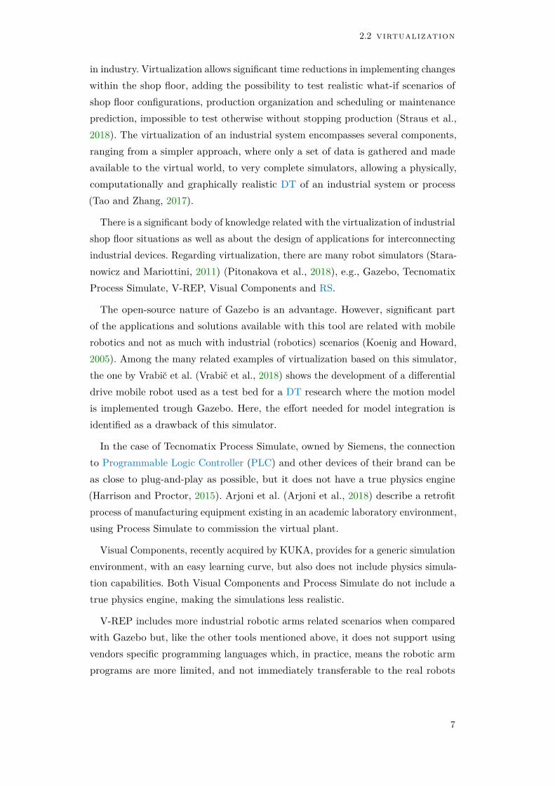
in industry. Virtualization allows significant time reductions in implementing changeswithin the shop floor, adding the possibility to test realistic what-if scenarios ofshop floor configurations, production organization and scheduling or maintenanceprediction, impossible to test otherwise without stopping production (Straus et al.,2018). The virtualization of an industrial system encompasses several components,ranging from a simpler approach, where only a set of data is gathered and madeavailable to the virtual world, to very complete simulators, allowing a physically,computationally and graphically realistic DT of an industrial system or process(Tao and Zhang, 2017).
There is a significant body of knowledge related with the virtualization of industrialshop floor situations as well as about the design of applications for interconnectingindustrial devices. Regarding virtualization, there are many robot simulators (Stara-nowicz and Mariottini, 2011) (Pitonakova et al., 2018), e.g., Gazebo, TecnomatixProcess Simulate, V-REP, Visual Components and RS.
The open-source nature of Gazebo is an advantage. However, significant partof the applications and solutions available with this tool are related with mobilerobotics and not as much with industrial (robotics) scenarios (Koenig and Howard,2005). Among the many related examples of virtualization based on this simulator,the one by Vrabic et al. (Vrabič et al., 2018) shows the development of a differentialdrive mobile robot used as a test bed for a DT research where the motion modelis implemented trough Gazebo. Here, the effort needed for model integration isidentified as a drawback of this simulator.
In the case of Tecnomatix Process Simulate, owned by Siemens, the connectionto Programmable Logic Controller (PLC) and other devices of their brand can beas close to plug-and-play as possible, but it does not have a true physics engine(Harrison and Proctor, 2015). Arjoni et al. (Arjoni et al., 2018) describe a retrofitprocess of manufacturing equipment existing in an academic laboratory environment,using Process Simulate to commission the virtual plant.
Visual Components, recently acquired by KUKA, provides for a generic simulationenvironment, with an easy learning curve, but also does not include physics simula-tion capabilities. Both Visual Components and Process Simulate do not include atrue physics engine, making the simulations less realistic.
V-REP includes more industrial robotic arms related scenarios when comparedwith Gazebo but, like the other tools mentioned above, it does not support usingvendors specific programming languages which, in practice, means the robotic armprograms are more limited, and not immediately transferable to the real robots
7

fundamental concepts and related work
(Visual Components includes converters for vendors specific languages, but only fora small set of instructions).
RS provides a simulation environment with some similarities with Visual Compo-nents, but specific for ABB robots. Nevertheless, it is capable of simulating manycomponents present on today’s factories by importing their 3D models and adding adynamic and responsive behaviour, which can be extended by the user through theavailable RS Software Development Kit (SDK)2, a well documented feature reachtool. Furthermore, besides having recently added physics simulation capabilities,it allows for the complete set of RAPID (ABB robots programming language)instructions to be programmed and tested, albeit only limited with ABB robots(additional non-ABB robots could be added, but would required a considerableamount of work and would not provide the same degree of compatibility as with theABB robots). Forgó et al. (Forgó et al., 2018) address the benefits of using ABBRS software with the use of SmartComponent (SC), which can interact with therobot virtual controller as inputs and outputs, from and to the simulated process.
2.3 digital twin
One of the concepts of Industry 4.0 with many uses in Smart Factories, is the DT,referred to for the first time by Michael Grieves in 2002, during a presentation onProduct Lifecycle Management (PLM) (Grieves and Vickers, 2016). After that, theNational Aeronautics and Space Administration (NASA) and the US Air Forceapplied DT in their maintenance and for the remaining useful life prediction ofaerospace vehicles (Tao, Qi, et al., 2019). The DT is the virtual and computerizedcounterpart of a physical system, which can also be divided into three subcategories,according to their level of data integration: Digital Model, Digital Shadow and DT(Kritzinger et al., 2018).
Ayani et al. (Ayani et al., 2018) presented an industrial application where em-ulation tools are used to create a DT of an old industrial device to support thereconditioning project. They propose a methodology that tries to maximize theuses of the built DT in several phases of the system’s lifecycle, in order to make themost of the required extra time consumed to build it, i.e. employing DT in otherphases rather than restricting its use to the design, development and simulation.
Concerning the use of virtual engineering to achieve lifecycle support of automatedsystems, Konstantinov et al. (Konstantinov et al., 2017) demonstrate the use of
2 https://developercenter.robotstudio.com/robotstudio-sdk
8

2.4 virtual commissioning
CPS-enabled virtual engineering tools within a practical workflow to complementexisting engineering tools and methods, using a real industrial scenario as a testbed.This work demonstrated the use of the VueOne3 toolset up to the build phase of amachine using a common model. The authors mentioned that their future work willshow how this model can be truly exploited throughout product lifecycle. Jbair et al.(Jbair et al., 2019) also used the VueOne toolset for automatic PLC structured codegeneration, based on a virtual engineering model and available process planing data,together with OPC UA communication blocks, aiming to obtain the connected DTand gain other benefits, such as data analytics.
2.4 virtual commissioning
VC is typically viewed as a Hardware-in-the-Loop (HiL) configuration that is usedbefore real (physical) commissioning of an industrial device or plant, with thepurpose of testing and verifying the control logic. However, there are other relatedconcepts, such as Hybrid Commissioning, where the real controller is simultaneouslyconnected to the real industrial equipment and to the simulation model. Thecore advantage of carrying out VC is the reduced physical commissioning time.Additionally, an accurate simulation model, the so-called DT, which can be usedthroughout the real system’s life span, is created. (Khan et al., 2018).
Fernandez et al. (Fernández et al., 2019) use the Simumatik3D4 software toachieve the VC of PLC programs for a robotic cell in an academic environment.This software is presented as a recently launched open emulation platform, whichallows the development of digital models of industrial equipment to support theentire lifecycle of automated solutions. The authors suggested, as future work, theuse of this technology in other phases of the engineering lifecycle, not only in thevalidation of PLC programs.
The Factory I/O5 software, from Real Games, is described by Riera et al. (Rieraand Vigário, 2017) as a new generation of 3D factory simulation for learning automa-tion technologies. The highly interactive environment, which allows the introductionof disturbances on the controlled plant and faults in sensors and actuators, is iden-tified as an important feature of this software. The authors mentioned that, at thetime they wrote the paper, the VC use of Factory I/O for pedagogical applications
3 https://warwick.ac.uk/fac/sci/wmg/research/digital/automation/4 https://www.simumatik.com/5 https://factoryio.com/
9

fundamental concepts and related work
had been successfully tested. Here, the impossibility of importing or creating new3D models into Factory I/O is identified as a drawback.
A growing number of companies have recently shown an interest in this technology,mostly related with Industry 4.0, as it reduces the time and cost of introducingnew products and allows different scenarios to be evaluated and validated withthe manufacturing controllers in the virtual environments, prior to the physicalcommissioning (Riera and Vigário, 2017). VC can be seen as part of the PLM,which is an integrated driven approach to all aspects of a product, from its designinception through its manufacture, deployment, maintenance and end-of-life.
2.5 machine monitoring
Nowadays, many industrial sectors use some type of direct data collection in theindustrial process. However, neither its application is universal, nor the level ofadhesion from companies is similar and the depth of existing implementations isuniform. The best examples are in industries with automatic assembly lines, suchas electronics or automotive industries, areas in which automation is already veryextensive and where process data, therefore, is easily available (Giessbauer et al.,2018).
The molds industry has been a pioneer in automatic manufacturing, namely inCNC technologies, typically in milling, turning and electric discharge machining,and the problems with the connection to the machines has been solved regardingthe transmission of the programs from machining software. In the other direction,i.e. in the collection of information about the state of the process or the equipment,the state of the development is poor, being neither universal, nor done with thesame depth in all companies.
There is significant research related to CNC machines monitoring techniques,especially with tool condition monitoring. For instance, in the work carried byDowney et al. (Downey, Bombiński, et al., 2015) (Downey, O’Sullivan, et al., 2016),the authors collects and analyses data from three sensor technologies (force, acousticand vibration) in a real time production environment, to monitor CNC tool wear.Other works, like the one by René de Jesús et al. (René de Jesús et al., 2003) andthe one by Stavropoulos et al. (Stavropoulos et al., 2016), uses driver current signalanalysis on tool wear and breakage detection.
10

2.6 open platform communications unified architecture
Concerning the use of OPC UA standard on monitoring CNC machines over awider range of parameters, there are fewer implementations and results available,of which the two most relevant are described here. The work from Mourtziz et al.(Mourtzis et al., 2018) proposes an OPC UA-based framework for the modelling ofmilling and lathe CNC machine-tools. They also developed a data acquisition deviceto allow the integration of legacy machine-tools, without connectivity capabilities,in their holistic framework, presenting a laboratory case study to validate theproposed system. Liu et al. (Liu et al., 2019) propose a Cyber-Physical MachineTools (CPMT) platform based on OPC UA and MTConnect to enable standardized,interoperable and efficient data communication between machine tools and varioustypes of software applications. To demonstrate the advantages of the proposedCPMT platform, different applications were developed, including an OPC UA client,augmented reality assisted wearable Human-Machine Interface, and a conceptualframework for a CPMT-powered cloud manufacturing environment. These twoworks have their major developments around data acquisition using external sensors,giving less relevance to the direct data exchange with the CNC machine controllers.
2.6 open platform communications unified architecture
The main supporting technology of the developed work is the OPC UA standard.In this section, a brief description and the main characteristics of this standard arepresented.
Defined by the international standard IEC 62541, OPC UA is the approach fora communication layer implementation recommended by the German ReferenceArchitecture Model Industrie 4.0 (RAMI 4.0)7 industrial platform (De Melo andGodoy, 2019). OPC UA is a standard that, due to its characteristics, ensuresopen connectivity, interoperability, security, scalability and compliance of industrialdevices and systems. Based on a multi-layered architecture (see Figure 2), where asingle server supplies all the information and services with active security, from agiven system, OPC UA is much more than a protocol. It has built-in informationmodels and defines basic rules for information exchange and interfaces.
6 https://opcfoundation.org/about/opc-technologies/opc-ua/7 https://www.plattform-i40.de/
11

fundamental concepts and related work
Figure 2: OPC UA Architecture.6
2.6.1 Open connectivity
OPC UA comes as a successor of OPC Classic8, but supporting multiple operatingsystems. OPC Classic can be configured to provide a fair amount of security, butby relying on Microsoft Windows and DCOM/COM functionalities, it is difficult tosetup in other operating systems. On the other hand, OPC UA was designed towork in multiple environments and on multiple platforms, with security built intothe platform from the start (Hunkar, 2014).
2.6.2 Interoperability
In order to allow interoperability, OPC UA uses the Address Space concept torepresent all the information generated from a specific system or device. This datais usable and can be interpreted by other systems using the same protocol, withits structure being built on information models, resulting on a standardized wayto represent all data and information to be accessible by client systems. OPC UAuses the concept of object to represent system data and behavior. Objects serve as
8 https://opcfoundation.org/about/opc-technologies/opc-classic/
12

2.6 open platform communications unified architecture
locations to store variables, events and methods, being also able to connect to eachother using references.
The standard information model is designed to allow type definition so thatdesigners can meet their own application needs and, on top of this, informationmodels can also be combined for specific areas, such as CNC systems (VDW andOPC Foundation, 2017), Robotics (VDMA and OPC Foundation, 2019b) andMachine Vision (VDMA and OPC Foundation, 2019a), to name just a few. Thesespecific models are called Companion Specifications (CS) and derive from thestandard model, inheriting its features, but can also include modifications, whichcan also be combined, depending on the system’s needs. The released CS can befound on OPC Foundation official GitHub repository9. In the development of theseCS, some of the reference companies in the automation and robotics fields such asABB, KUKA, or SIEMENS were actively involved, which underlines the importanceof this movement.
2.6.3 Security
OPC UA gives a lot of importance to the secure communication between client andserver, addressing a broad range of applications, and encompassing different securityand timing requirements. The available security modes, shown in Table 1, can enableboth digital signature and encryption mechanisms, only digital signature mechanisms,or none of them. An OPC UA client can choose the desired security mechanismsfrom the ones available by a specific OPC UA server. After a secure channel (andsession) has been established between server and client, there is still the need foruser credentials represented by another certificate, or by a username/passwordcombination (Cavalieri et al., 2019). Bearing in mind that most of the OPC UAapplications are within industrial environments, security issues should not beforgotten, as cyberattacks to this environments may compromise their normaloperation. The OPC UA security analysis (Sicherheit in der Informaationstechnik,2017), commissioned by the German Federal Office for Information Security, presentsrecommended measures and procedures that should be followed when implementingOPC UA-based solutions.
9 https://github.com/OPCFoundation/UA-Nodeset
13

fundamental concepts and related work
Table 1: OPC UA security modes (Neu et al., 2019).Mode Properties
None No security.
Sign
Encoded with sender’s private key.Only certificate owner has the private key.Anyone can verify the identity.Provides authenticity.
SignAndEncrypt
Adds encryption to sign.Encoding with receiver’s public key.Anyone can encrypt.Only the certificate owner can read.Authenticity, confidentiality and integrity.
2.6.4 Scalability and Compliance
Various OPC UA profiles are defined, as show in Table 2, with different applicationscenarios in mind, allowing OPC UA to scale down to a chip level, using the NanoEmbedded Device profile, while still retaining its prominent features (Imtiaz andJasperneite, 2013). On the opposite side, when the implementation of complexscenarios is required, a PC-based server using the Standard UA profile could be theadequate solution. The OPC Foundation developed the UA Compliance Test Tool(UACTT)10, as a way to identify which profiles are supported by our application,and to verify if the designed OPC UA server or client is compliant with the OPCUA specification.
2.6.5 Communication Mechanisms
For information exchange, OPC UA offers two main communication mechanisms:Client-Server and Publish-Subscribe (PubSub) (Drahos et al., 2018). In the Client-Server mechanism, the client accesses the information provided by the serverthrough defined services. The PubSub mechanism can be applied in different ways:for messaging over local area networks (LAN), data is published by the OPCUA server (publisher) and consumed by multiple authorized OPC UA clients(subscribers), using Time Sensitive Networking (TSN) to allow real-time low delaycommunications; for messaging over global networks (WAN/Cloud), OPC UA
10 https://opcfoundation.org/developer-tools/certification-test-tools/opc-ua-compliance-test-tool-uactt/
14

2.6 open platform communications unified architecture
Table 2: OPC UA profiles (VDMA and Fraunhofer IOSB-INA, 2017).Profile Characteristics
NanoEmbeddedDevice
Limited functionality only, for very small devices,e.g. sensors. Only one connection, but without UAsecurity, no subscriptions and no method calls possible.
MicroEmbeddedDevice
Restricted functionality, at least two parallelconnections, additional subscriptions and datamonitoring, but no UA security and no method calls.
EmbeddedUA
Basic functionalities of OPC UA are available plusUA security and method calls.
StandardUA
Includes all functionalities for secure information accessincluding UA security. No alarms and no history.PC-based servers should support at least this profile.
PubSub specification (OPC Foundation, 2018) defines mappings on protocols suchas, for instance, MQTT11.
Regarding the use of OPC UA, Ayatollahi et al. (Ayatollahi et al., 2013) createdan information model and a prototype OPC UA Server using it for data acquisition,event generation and remote control of a machine tending industrial robot. At thetime, they identified a problem related with the insufficient standard communicationinterfaces which, even with the introduction of the OPC UA standard, still lackeda generally accepted semantic description of devices used in the manufacturingplant. Since then, some progress was made with the recent releases of several CSby the OPC foundation in collaboration with important industry partners, whichintroduces standard information models to describe these devices.
The automotive manufacturer, Renault, has also adopted OPC UA as theircompany standard for machine-to-machine communications. This company willboth retrofit existing machines, as well as purchase new OPC UA-capable machinesto establish an industrial data management platform based on Google Cloud. Thiswill also allow Renault to standardize the data model describing their operationsglobally.12
11 http://mqtt.org/12 https://youtu.be/WwR_6VHuN4Q
15


3C N C M A C H I N E S M O N I T O R I N G
This chapter describes the methodology developed for the implementation of a CNCmonitoring solution based on an OPC UA server. The development of a genericC# class is explained, as well as the chosen approaches for data exchange with theCNC machines. Details of the implementations referred on this chapter are furtherdescribed on a technical manual (André Martins, Costelha, Neves, and Bento, 2020a)and a user manual (André Martins, Costelha, Neves, and Bento, 2020b) that werecreated within this work.
With the current market diversity of CNC controllers, and given that some of thisequipment is not open to third-party applications, the direct interaction with thecontroller becomes extremely difficult. On the other hand, more recent equipmentoften has an available communication protocol, and some even have an SDK, anApplication Programming Interface (API), or simply the definition of a group ofmessages that can be exchanged with the equipment to this end. Alternatively tothe acquisition methods using the information provided by the CNC controllers,direct access to the sensors already integrated, or externally added to the CNC, canalso contribute for the collection of performance metrics, which in turn will allowthe prediction of some machine states and/or events.
3.1 generic c# class
In order to accommodate all this variety of paradigms, a generic C# abstract class(CNCBase) with abstract methods was developed to help modeling a generic interfacefor any CNC machine, allowing the development of a monitoring application whichcan work with different CNC machines. With this type of implementation, each CNCmachine specific brand then overrides the generic class with its specific functionsaccording to its specific communication interfaces, when needed, but exchangingthe information available using the same information model (see Figure 3).
This kind of implementation makes the future incorporation of other CNC machinemodels more straightforward. Another relevant component of our application is
17

cnc machines monitoring
CNCBase(Abstract)
Method A(Abstract)
Method B(Abstract)
HeidenhainController
Fanuc Controller
EdingController
Method A(Fanuc Override)
Method B(Fanuc Override)
Method A(Heidenhain Override)
Method B(Heidenhain Override)
Method A(Eding Override)
Method B(Eding Override)
( )
( ) ( ) ( )
XController
Method A(X Override)
Method B(X Override)
( )
( )
Figure 3: Generic C# abstract class and methods.
a configuration file, which allows the definition of some application parameters,such as the CNC machine model/brand to be monitored, the communicationaddress definition to be used, as well as the machine parameters and frequencyto be monitored. The main goal of this file is the definition of run-time functionparameters, i.e., without the need to recompile the server application for specificmachines, or, for instance, whenever different data is to be acquired, or is to beacquired at different sampling rates.
Entries in this file respect the following syntax:
<add key=”Name” value=”NodeID,Enabled,Time”/> where
• Name – Method name;
• NodeID – Node number from address space where the value is updated;
• Enabled – Parameter that enables this entry.
• Time – Value that represents time interval between variable update.
As an example, the following code presents one possible entry from the XMLconfiguration file, where the “Get_x_dir_actpos” method is indicated to be calledto update the value of the node with the id of 6008, every 1 second.
<add key="Get_x_dir_actpos" value="6008,false,1" />
18

3.1 generic c# class
Another feature of this configuration file is its first part, where it is possible tospecify a set of configuration parameters for each application, such as, for instance:
<add key="CNC_CONTROLLER" value="FANUC" />
<add key="CNC_IP" value="192.168.1.4" />
<add key="CNC_PORT" value="8193" />
<add key="POWER_METER_IP" value="192.168.1.2" />
<add key="POWER_METER_PORT" value="502" />
<add key="VIDEO_IN_PATH" value="http://24.181.120.98:8080/" />
<add key="VIDEO_OUT_PATH" value="../../../videos/" />
<add key="VIDEO_FPS" value="30" />
<add key="VIDEO_DURATION" value="10" />
<add key="INFLUXDB" value="true" />
where,
• CNC_CONTROLLER – Allows the definition of the CNC controller model, useinternally to choose the correct methods for each specific CNC brand andmodel;
• CNC_IP – Allows the definition of the IP address which the developed applica-tion will use to connect to the CNC controller;
• CNC_PORT – Allows the definition of the port which the developed applicationwill use to connect to CNC controller;
• POWER_METER_IP – Allows the definition of the IP address which the developedapplication will use to connect to an energy meter;
• POWER_METER_PORT – Allow the definition of the port which the developedapplication will use to connect to an energy meter;
• VIDEO_IN_PATH – Allows the definition of the path to a video stream source;
• VIDEO_OUT_PATH – Allows the definition of the path to save the generatedvideos;
• VIDEO_FPS – Allows the definition of the generated videos frames per second;
• VIDEO_DURATION – Allows the definition of the video duration (in seconds);
• INFLUXDB – Allow to set the use of a specific database, in this case InfluxDB.
This generic class was initially developed without any relation to the OPC UA,so it can still be used if there is a paradigm shift in terms of its usage in theseapplications. As an example, the first version of the CNCMonitor application, was
19
cnc machines monitoring
developed with the sole objective of collecting data from a CNC, directly to anInfluxDB TSDB (Time Series Database).
3.2 using a software to design opc ua information models
OPC UA is the next generation solution compared to OPC Classic. One of the mostimportant improvements in OPC UA is a powerful Information Model concept: theAddress Space. OPC UA allows exposing real-time process data and underlyinginfrastructure as a consistent information model built up with nodes. The processmodel is represented by nodes, attributes, and their mutual relationships. Therefore,using OPC UA this powerful concept allows one to expose not only raw process databut also entire consistent information sets about the process state and behavior. Theflexibility of OPC UA ensures that no existing or future systems are too complexto be exposed via OPC UA. Of course, such flexibility leads to difficulties duringdesign, development, and deployment, thus the importance of using specific softwarethat was developed to help with information model design, such as:
• UAModeler1 from Unified Automation – Requires an account for softwaredownload, with the free version not allowing C# code generation and supportfor <UANodeSet> (official format for files containing sets of OPC UA nodes);
• UA Model eXcelerator Professional (UMX Pro)2 from Beeond – Thistool enables developers to graphically configure an OPC UA compliant infor-mation model, produce, merge and manipulate <UANodeSet> files and generateSDK independent code;
• OPC-UA-Modeler3 from Fraunhofer IOSB – Web-based graphical tool todevelop information models;
• Free OPC UA Modeler4 – Free and open source tool, that operates andoutputs <UANodeSet> files types;
• Siemens OPC UA Modeling Editor (SiOME)5 – Free tool, createdby Siemens, to define OPC UA information models or mapping existingcompanion specifications on a SIMATIC PLC. This tool allows to import
1 https://www.unified-automation.com/products/development-tools/uamodeler.html2 https://beeond.net/umxpro/3 https://www.iosb.fraunhofer.de/servlet/is/35891/4 https://github.com/FreeOpcUa/opcua-modeler5 https://support.industry.siemens.com/cs/document/109755133/
siemens-opc-ua-modeling-editor-(siome)-for-implementing-opc-ua-companion-specifications?dti=0&lc=en-WW
20

3.3 opc ua server
and edit information models as XML files, or to generate and to exportindividualized models;
• Object Oriented-Internet Address Space Model Designer (ASMD)6
from CAS – Initially a commercial product of CAS Lodz Poland, this opensource information model design tool with embedded ModelCompiler7 fromOPC Foundation allows working with <ModelDesign> file types to generate<UANodeset> files, C# and ANSI C source code.
At the time this research started, this kind of software either was not open sourceor the trial versions had very few features enabled. Therefore, it was decided todevelop the generic C# abstract class (CNCBase) described in the Section 3.1with abstract methods, to help modeling the interface for a generic CNC machine,allowing the development of monitoring application which work with different CNCmachines. With this type of implementation, each CNC machine specific brand thenoverrides the generic class with its specific functions from its specific communicationinterfaces, but exchanging the information available using the same informationmodel.
Recently, since the founder and Executive Director of CAS, Lodz Poland, decidedto open-source the ASDM software, this software was explored in this work andused to both modify the information model, and generate the files needed to buildthe address space of the built OPC UA servers. Based on the CNC CS, a new CNCmachine information model was built, replacing this functionality from CNCBase.In what concerns the machine to sensor data connection the C# CNCBase class isstill being used. In future developments of this work, it will be interesting to explorethe data bindings feature of ASMD (leveraging machine to sensor connectivity)coupling the Address Space variables with the process (sensors, actuators, etc.)making an in-memory process replica.
3.3 opc ua server
With the goal of making the collected information available using a standardizedapproach, the OPC UA protocol was chosen. OPC Foundation provides severalimplementations in different programming languages. We chose to use the .NETstack version that is available as an open-source project8, currently with a license
6 https://github.com/mpostol/ASMD7 https://github.com/OPCFoundation/UA-ModelCompiler8 https://github.com/OPCFoundation/UA-.NETStandard
21

cnc machines monitoring
that allows developments within education and research fields. The .NET version ofOPC UA is the one with most support and available implementations backed by theOPC Foundation. Furthermore, the use of the .NET Framework approach allowsthe developed OPC UA servers to run on Windows, Linux and macOS (using .NETCore9), as well as in embedded systems applications (using nanoFramework10). Thedevelopment of the application in this work is based on the Reference Server11,given that it was certified to be used in industry by UA CTT12.
In order to define the Address Space of our OPC UA Server, the CNC CS (VDWand OPC Foundation, 2017) was considered, specifically following the OPC UAinformation model example of a 3-axis machine tool, as shown in Figure 4 (whichcan easily be adapted or extended to a different number of axis). After a first versionbuilt using UAModeler and the CNCBase class, the more recent version of theinformation model that defines CNC machines in this case, was developed usingthe ASMD software, mentioned on Section 3.2. This tool provides a graphical andhierarchical representation of the designed model, following the OPC UA notationand syntax.
Figure 4: 3-Axis machine tool OPC UA information model (VDW and OPC Foundation,2017).
9 https://docs.microsoft.com/en-us/dotnet/core/10 https://nanoframework.net/11 https://github.com/OPCFoundation/UA-.NETStandard/blob/master/SampleApplications/
Workshop/Reference/README.md12 https://opcfoundation.github.io/UA-.NETStandard/help/overview_referenceserver.htm
22
3.4 data exchange with the cnc controller
3.4 data exchange with the cnc controller
The implementation built within this work prioritizes the CNC machine interactionby means of a communication protocol, SDK or API, when available. In additionor alternatively to this, when the above methods are not supported, but when alog system is still available, a group of messages is defined and implemented withinthe machining code, which can be sent from the equipment during the machiningprocesses. This can be automated, by adding, for instance, in the FANUC case,DPRNT instructions to the ISO code in the CNC machine post-processor phase.
In addition to the acquisition methods referred above, or when the CNC machinecontroller does not support any type of communication, one can use a direct(hardware-based) access to the sensors already integrated or externally added tothe CNC machine, in order to acquire the needed data directly. In these cases, thechosen approach relies on devices that have wireless and/or wired network support,allowing to take advantages of both wired and wireless-based solutions (Underberget al., 2018), having in mind the tight requirements often imposed by industrialenvironments (Cena et al., 2008).
The next subsections will provide further details about the methodology fordeveloping OPC UA servers for CNC machines, by describing the application tospecific scenarios, considering three different CNC controller vendors.
The specific case studies were selected based on the main equipment brands andoperations used by molds industry companies in the Marinha Grande cluster, inPortugal, and within our research lab. As shown on Figure 5, two types of CNCcontrollers used in the industry were chosen, namely the FANUC 31i-A and theHeidenhain iTNC530 CNC controllers, and, as part of a parallel project relatedwith a CNC retrofitting process, an Eding CNC controller.
3.4.1 FANUC CNC machine
In what concerns data exchange with the 31i-A FANUC controller, the FOCAS(FANUC Open CNC API Specifications) library is used. This library allows dataaccess from the CNC and PMC (Programmable Machine Control) controllers viaEthernet or HSSB (High Speed Serial Bus) (Fanuc and Inventcom, 2018). TheFOCAS library, in both the 1 and 2 versions, contains numerous functions13 that
13 https://www.inventcom.net/fanuc-focas-library/general/general
23

cnc machines monitoring
CNC controller (FOCAS)
External data acquisition (embedded system) CNCBase(Generic C# class)
Server
Ethernet|HSSB
Ethernet|WiFi
OPC UA Clients
OPC UA data
EnterpriseResourcePlanning
(ERP)
ManufacturingExecution
System(MES)
DataBase
OPC UAMain Server
OPC UA data
OPC UA data
CNC controller (SuperCom)
External data acquisition (embedded system) CNCBase(Generic C# class)
Server
Ethernet|Serial
Ethernet|WiFi
CNC controller (cncapi)
External data acquisition (embedded system) CNCBase(Generic C# class)
Server
Ethernet|USB
Ethernet|WiFi
Figure 5: Functional diagram and interaction between systems.
enable data exchange with FANUC CNC machines (Atluru and Deshpande, 2009).However, this library is not supported by all the FANUC controller families, beingrestricted to machines from the i series. This library can be used for developmentof Windows and Linux-based applications, as well as for Android and iOS mobileplatforms.
Furthermore, FANUC controllers provide several commands that can outputvariable values and various characters through the RS232 or embedded Ethernetport to externally connected devices. These commands are called External OutputCommands, and there are four of them: POPEN (Port Open) and PCLOS (PortClosed) are used to "connect" and "disconnect" to the output port, respectively;between these two instructions one can use BPRNT and DPRNT commands tooutput data in binary or ASCII formats, respectively (Smid, 2005). These commandscan be added in the post-processor phase, allowing the acquisition of some machineparameters when the FOCAS library is not supported by the specific controller, orwhen the FOCAS library does not provide access to the needed information.
3.4.2 Heidenhain CNC machine
The solution used to exchange data with the Heidenhain iTNC530 controllerswas based on the SuperCom Heidenhain communication library14. This Adonteclibrary allows communication with Heidenhain TNC controllers through the serial orEthernet (TCP/IP) ports, similarly to FOCAS for FANUC controllers. This librarycontains functions to build data connections to one or more Heidenhain controllers.SuperCom is event-driven, and enables file transfer to and from the Heindenhain
14 https://adontec.com/
24
3.5 external sensorization - industrial equipment
TNC, listing, creating and deleting folders, renaming and deleting files, readingTNC configuration data, retrieving machine status, machine data and process data,as well as reading and writing memory registers, among other functionalities. Theamount of information available may vary between the different controller series.The library also contains direct access functions that can be used to retrieve ormodify data directly from the controller connected PLC memory. This library canbe used for developing both Windows and Linux-based applications, although aspecific license is needed for each platform.
3.4.3 Eding CNC machine
Our research lab as been recently involved in a CNC retrofitting project (Lucas,2019), using an Eding controller board15. In this case, data is exchanged with thecontroller through the USB or Ethernet (TCP/IP) interface using the cncapi16
communication library. This library allows sending and receiving data by sharingits internal functions, which are also used by the graphical user interface thatallows viewing and controlling the Eding CNC controller. An OPC UA server wasimplemented using the methodology described above, in order to work in paralleland communicate with the Eding software. It is possible to exchange data with allthe Eding controllers using this library, independently of the device to be controlled.Note, however, that the library only works on Windows. The Eding library is notavailable in C#, but only in C++. As such, an existing C++-based code wrapperfor C# was used17, so that data could be accessed from the developed OPC UAserver, built using C#.
3.5 external sensorization - industrial equipment
In what concerns the incorporation of industrial devices in the developed OPC UAserver, two examples where added to the system: a power meter used to monitorthe power usage of the CNC machine, and a camera to monitor and record themachining process in case of alarm events from the CNC machines.
15 https://www.edingcnc.com/products.php16 The cncapi and its documentation is only available after installation of the Eding CNC Software.17 https://www.oosterhof-design.com/cncapi-netframework/
25

cnc machines monitoring
3.5.1 Power Meter
In this specific case, the industrial device integrated in the developed OPC UAserver is an EMpro EEM-MA37018 energy analyzer, from Phoenix Contact. Thisequipment make its information available through the Modbus19 TCP protocol (aversion of the protocol intended for use over a TCP/IP network).
The Modbus protocol does not have any cybersecurity feature incorporated inits specification (users, passwords, certificates, or others). On the other hand, thedeveloped OPC UA server has the ability to provide these same security services,necessary for the communication with an external client.
As such, the device that communicates via Modbus and the computer withthe OPC UA server need to be located on a private network, protected by afirewall, which prevents unauthorized access from outside (see Figure 6), or to use apoint-to-point connection.
Figure 6: Diagram representing the communication security between devices.
The developed OPC UA application is a Modbus TCP client in terms of commu-nication with the energy analyzer. For external clients, the application is an OPCUA server that interfaces with the energy analyzer securely.
There are several Modbus libraries available. In this case, the open-source Easy-Modbus20 library was used. This communication protocol is widely disseminated inthe industry, making this implementation particularly useful in every cases in whichthe industrial device to be integrated has this communication protocol available.
18 https://www.phoenixcontact.com/online/portal/us?uri=pxc-oc-itemdetail:pid=290798319 https://www.ni.com/pt-pt/innovations/white-papers/14/the-modbus-protocol-in-depth.
html20 https://sourceforge.net/projects/easymodbustcp/files/latest/download
26

3.6 external sensorization - development of dedicated hardware
3.5.2 Camera
Another example of an industrial equipment integration is the use of a camera.Currently the main goal of using the camera is to acquire video footage (with lowerquality and only for less detailed remote monitoring) of the machine’s operation,generating videos in each event created by OPC UA related with CNC alarms.
In order to achieve this, a FIFO (First-In, First-Out) system was implemented,using a C# linked list that contains the last frames of the CNC event. Each timea CNC alarm event occurs, a method is called and the last frames (the currentframes on the FIFO system) that contains the recollection of what happened inthe time just before, and up until, the event was captured, are saved to a videofile and stored in a shared folder. This method also returns the path to the savedvideo, making it accessible to the operation manager and client through the OPCUA server.
The cameras tested with the developed system were a Genie Nano C192021
(industrial camera) from DALSA Teledyne and a generic public IP network cameraavailable through an online internet stream. However, almost any camera supportingRTSP (Real Time Streaming Protocol) or UVC, among other protocols for accessingthe video stream, are also supported by the developed system.
Since industrial cameras are also supported by this system, in future developmentsof this work, machine vision techniques can be applied to achieve image analysis insome situations and, as a result, other types of information can be gathered.
3.6 external sensorization - development of dedicated hard-ware
To acquire additional data, the IoT development board ESP32-PoE22, from Olimexwas used. Built around the ESP32-WROOM-32 module (Espressif, 2019), it supportsWiFi, BLE and 100Mb Ethernet with Power-Over-Ethernet (PoE). It further includesa LiPo battery connector, a MicroSD card slot, GPIO (General Purpose InputOutput) headers and an UEXT (Universal EXTension) connector that allows theconnection of any device using I2C, SPI or RS232 communication. This board is
21 https://www.teledynedalsa.com/en/products/imaging/cameras/genie-nano-1gige/22 https://www.olimex.com/Products/IoT/ESP32/ESP32-POE/open-source-hardware
27

cnc machines monitoring
also available in a galvanic isolated version for the PoE power and in an industrialversion23, supporting an extended temperature range from -40 to 85.
Combining this hardware with the open62541 server, (open source version of OPCUA in C) it is possible to create OPC UA servers for devices with more limitedresources, which provide data from a given sensor, or set of sensors, to the mainserver. The development of these OPC UA servers, uses as starting point the projectfrom the opcua-esp3224 repository. This project uses the open62541 library to buildan OPC UA server to be used on a ESP32, with an information model that containsa temperature sensor (DHT22), a callback method to call the ESP32 onboard LEDand two relays, which can be remotely controlled as OPC UA objects.
Two implementations were developed: one that uses an LM35 temperature sensor,connected to an analog input, and another that uses an MPU6050 module, connectedthrough the I2C interface, which includes an accelerometer and 3-axis gyroscope,both with the objective of making the sensor data available through OPC UA to themain server. Using additive manufacturing technology, a case was built to protectthe electronics (see Figure 7), as well as allowing easier installation on a DIN rail inthe machine’s control cabinet.
Despite the specific use of LM35 and MPU6050 sensors, this device can bedeveloped to use any sensor that can be read using an ADC (Analog-to-DigitalConverter), I2C interface or any other protocol type available in the ESP32 (thischanges in the development might require some signal conditioning circuit dependingon the sensor specific output). Additionally, the information model used by theOPC UA server to expose the sensor should be changed, according to the specificsensor characteristics.
In order to explore this project and start changing it to our needs, the ESP-IDF environment needs to be configured, enabling project creation, building andflashing to the ESP32, as well as application debugging. In the technical manual(André Martins, Costelha, Neves, and Bento, 2020b), a result from this project, theinstructions to set up this development environment are defined.
23 https://www.olimex.com/Products/IoT/ESP32/ESP32-POE-ISO/open-source-hardware24 https://github.com/cmbahadir/opcua-esp32
28

3.6 external sensorization - development of dedicated hardware
Figure 7: Developed external sensorization for machine monitoring.
29


4D I G I TA L T W I N T O S U P P O RT P L M
This chapter describes the methodology developed and used to build a virtualmodel, the DT, and to integrate industrial equipment in a smart manufacturingenvironment, using the concepts described in the Chapter 2.
Study of the existent technical documentation
Functional description of the
systemSTEPS
PHASES Analysis and/or Reverse Engineering Development
ACTIONS
Rea
lV
irtu
al
Knowledge of geometrical 3D
model
Dynamic response behavior
Integrate OPC UA communication
Datasheets or technical reports
PLC programs, logic diagrams or
technical drawings
Importing 3D model of the equipment to RobotStudio
Using physics options of
RobotStudio
SmartComponent with OPC UA
Server or Client capabilities
Creation of OPC UA Server and
information model of the equipment
Commissioning and Validation
Test and Verify
Using simulation on RobotStudio
Life Time Monitoring
Tests in real environment
Monitor function
Working normally with OPC UA Server online
Monitoring with the OPC UA client SmartComponent
Changes in the control logic
Legacy equipment only
Figure 8: Methodology to support the design, commissioning and supervision of smartfactory components through their DT.
4.0.1 Integrating legacy industrial equipment and developing OPC UA-enabledequipment
Figure 8 illustrates the methodology developed for design, commissioning andsupervision of smart factory legacy equipment, including its DT development andintegration. After identifying the legacy equipment that shall be put through anIndustry 4.0 retrofit process, an analysis, with possibly some reverse engineering,needs to be done. Unlike in the integration of new industrial equipment in whichthe simulation model is created with the help of complete documentation, in legacyequipment, technical documentation may not be easily accessible. As such, it getsharder to create a robust and accurate simulation model that can serve as a virtualtwin. In the development phase, a 3D model with geometrical information of thedevice must be created, if one does not exist, and then imported to RS. The nextstep is to add dynamic and responsive behavior, which can be achieved through theavailable RS SDK, a well documented tool. In the third step, the fusion of the real
31

digital twin to support plm
and virtual/digital world is achieved by feeding virtual models with field data as wellas conveying information to the real device, using an OPC UA interface. This OPCUA interface in the real equipment should always be implemented as an OPC UAserver. The DT should act like an OPC UA server (in simulate mode) and like anOPC UA client (in monitor mode). When dealing with the integration of both legacyand recent equipment from different manufacturers some possible scenarios couldexist. Bellow you find a description of these scenarios and the proposed solutions:
• The equipment is controlled by a PLC with Classic OPC or OPCUA? If the automated system is controlled by a PLC, the brand and modelshould be investigated to find if it has the possibility of creating an OPC UAor a Classic OPC out of the box. When the equipment to integrate nativelysupports the OPC UA, this communication standard should be preferred forthe reasons mentioned in this report, and in this case the integration of suchequipment should require less effort compared with the following options. Ifthe option of Classic OPC is available an OPC UA COM Server Wrapperfrom OPC UA .Net Standard stack could then be implemented to map theinformation. This option enables to migrate to OPC UA-based systems, whilestill being able to access information from old existing OPC Classic systems.When the industrial equipment is in a retrofit process or in the developmentof new devices the use of OPC UA-enabled PLCs, such as Phoenix ContactPLCNext1, Siemens S7-15002 and Omron NJ/NX3, should be considered.
• The equipment is controlled by a PLC without Classic OPC or OPCUA? If the above features are not available in the PLC, other communicationprotocols should be used to develop the OPC UA interface. For example,using a Modbus server running directly on the PLC and then developing anOPC UA server as an external application running on a PC. Using the OPCUA SDKs from the OPC Foundation that acts like a Modbus client from thePLC point-of-view and, externally, act like an OPC UA server, making theinterface with PLC possible. There are some Modbus libraries available suchas, for instance, the open-source EasyModbus4.
• The equipment is controlled by a PC? If the automated system is runningon a PC, or has a PC-based controller, combining the OPC UA SDKs withAPIs from the automated equipment should be the way to build the server.
1 https://www.plcnext-community.net/en/2 https://new.siemens.com/global/en/products/automation/systems/industrial/plc/
simatic-s7-1500.html3 https://www.ia.omron.com/products/family/3705/4 https://sourceforge.net/projects/easymodbustcp/
32

digital twin to support plm
The OPC Foundation makes the stack available in different programminglanguages, however the one currently with most support and being tested andcertified is the .NET Standard5.
• The equipment is controlled by embedded systems? If the automatedsystem is based on embedded systems with low resources available, usingopen625416 is probably the best option. This low weight open-source Cimplementation of OPC UA is the appropriate option to use in embeddedsystems and it also supports the PubSub communication, thought its useis not yet certified due to the lack of official test cases and testing tools.The use of OPC UA in PubSub approach allows reaching multiple dataconsumers (subscribers) with a single message, the publisher is not sloweddown by the subscriber processing delays, thus providing higher efficiencythan session-based data exchange (client-server) (Gogolev et al., 2020).
In this step, some tests and verification should be done in the commissioning phaseto ensure the intended operation of the devices and their components is achieved,and that there is consistency between real and virtual environments. Finally, afterthe commissioning of the equipment, a constant monitoring is possible trough theOPC UA interface created previously.
4.0.2 Integrating OPC UA-enabled industrial equipment
Given the growing acceptance of OPC UA within industry, and with the continuedrelease of standard information models in many industrial equipment sectors, inte-grating new devices in this virtual environments is becoming easier, particularly interms of communication capabilities. Furthermore, modern industrial equipmentis usually provided with its 3D model and detailed, often digital, technical docu-mentation. As shown in Figure 8, the methodology for integrating new equipmentshares some stages with the one described for legacy equipment, excluding the needfor OPC UA server development on the device’s side, as well as for the initial phaseof analysis and reverse engineering on the existing equipment, rendering the taskeasier and swifter.
5 https://github.com/OPCFoundation/UA-.NETStandard6 https://open62541.org/
33

digital twin to support plm
4.0.3 Digital Twin modes of operation
Using ABB RS, and its SDKs a generic SmartComponent (SC) was developed,that can be associated to an industrial equipment to implement its DT. This SCprovides two working modes for the device it is connected to: simulate and monitor,as shown in the properties box in Figure 9.
When the RS simulation starts, and the SC WorkingMode property is set tosimulate, an OPC UA server will be launched, simulating all the aspects of the realindustrial devices. The address of the created server will show up in ServerToSimulateproperty box.
The other WorkingMode option available is monitor. When the RS simulationstarts in this mode, an OPC UA client will be launched and, if the securityrequirements are fulfilled, it will connect to the OPC UA server address inserted inthe ServerToMonitor SC property.
A variety of uses can be given to this OPC UA SC: firstly, during the designphase, the complete simulation can be used to validate design decisions. In a secondstage, it may be used to test individual (real) device integration with the rest ofthe (simulated) environment and to validate its real operation within the industrialprocess before commissioning the entire line. Finally, after commissioning, and duringregular operation, this implementation can be used for the continuous monitoringof the industrial equipment and process based on data analytics techniques, or justas a simple mimicking and monitoring of the real equipment behavior in the RSvirtual environment.
Figure 9: Developed OPC UA SC properties.
34

5T E S T S A N D R E S U LT S
This chapter presents several tests and results obtained from the application of thedeveloped methodologies described in this report.
5.1 opc ua server for cnc machines
The developed system was tested with three different CNC machine controllers bothin laboratory and industrial environment: Fanuc, Heidenhain and Eding.
Concerning Fanuc, the first tests were first carried in a laboratory environment,using the NCGuide1 CNC simulator. Some FOCAS functions are not availableon this simulator and, because of this limitation, the second stage of tests, weredeveloped in an industrial environment. Using the CNCMonitor application, referredon the Section 3.1, working as a datalogger. Data was continuously collected fortwo months from a CNC milling machine equipped with a Fanuc 31i-A controller,for experimental results. It should be noted that, to transition from the simulatorto the real machine, it was only necessary to change the IP of the controller andthe model in the configuration file, as the application worked flawlessly.
With Eding, tests were made only in the CNC simulator from Eding, given thatour retrofitting process was not yet finished. However, since the same software bothfor the Eding CNC simulator and the real CNC controller board, we do not expectperceivable differences.
Regarding Heidenhain, tests were only made with the iTNC530 CNC simulatorso far, with the main limitation of the trial version of the simulator (which weused) being the maximum program size of 100 lines of machine instructions. Due tothis limitation, in this test, unlike the others, the CNC axis are moved manually,reflecting these changes in cutter position in the OPC UA server variables.
In what concerns the information model, an hierarchically structured addressspace of the OPC UA server of one of the CNC machines is shown in Figure 10as an example. Server address spaces can be accessed with appropriate OPC UA
1 https://www.fanucamerica.com/products/cnc/software/cnc-guide
35

tests and results
generic clients such as, for instance, the UAExpert2 from United Automation, whichwas used in this case.
Figure 10: CNC machine OPC UA server address space structure.
A video obtained during these tests is available in the following link: https://youtu.be/VpfkCkDUswU.
5.2 digital twin to support plm
This section first describes the developed scenario and the manufacturing process,followed by the operation modes of the generic SC, built to embody the applicationof methodologies described in Section 4. It then presents several tests of theirapplication and the corresponding results.
5.2.1 Description of the scenario
The developed scenario consists of a system created in the robotics laboratory ofthe Polytechnic of Leiria, mainly used for research, development and education,composed by several devices (see Figure 11):
• R1 - Scorbot ER IX robotic arm;
• R2 - Scorbot ER IX robotic arm;
2 https://www.unified-automation.com/products/development-tools/uaexpert.html
36

5.2 digital twin to support plm
• R3 - ABB IRB1200 industrial robotic arm;
• R4 - KUKA KR6 ARC industrial robotic arm;
• R5 - ABB IRB2400 industrial robotic arm;
• C1 - Intelitek pallet conveyor;
• C2 - Belt conveyor (in-house development);
• V1 - BVS-1280M-INS Teledyne Dalsa camera;
• V2 - UI-5240CP-C-HQ IDS camera;
• CNC - ProLIGHT 1000 milling machine;
• AW - Automatic warehouse (in-house development).
R5 V2 V1
R4CNC
R2
C1
AW
R1
C2
Figure 11: Robotics laboratory of Polytechnic of Leiria.
5.2.2 The Manufacturing Process
The functional block diagram, including device physical interactions, is described inFigure 12. This diagram summarizes each device communication and/or I/O capa-bilities, while also showing a high-level description of the developed manufacturingprocess scenario.
The manufacturing process begins in the Parts Supplier storage cell, where aplastic part is supplied by a specific mechanism, one at a time. When the part isavailable, the R1 arm picks it up from the supplier mechanism and places it on oneof the pallets available on the workstation. Then, this pallet is moved to the shuttlelocated on the C1 conveyor (the shuttles, which are in the conveyor at all times,
37

tests and results
PLC Omron
RS232 KUKA KR6 ARC
Warehouse
Buffer 2
CNC ScorbotER IX
ABB IRB2400
ABB IRB1200ABB PC
Interface
ScorbotER IX Supplier
Vision Inspection
Assembly
Prox. Detector
Actuator
C
MA P&PP&P
P&P
P&P P&P
I/O
– Physical Interaction: Pick&Place (P&P), Mechanical Action (MA) or Object Detection (OD)– Digital Interaction: Input/Output (I/O) or Communication (C)
TCP/IP ABB PC Interface
RS232
OPC UA Wrapper
OPC UA Wrapper
RS232
C
OPC UA Wrapper
C
CP&P
C
P&P C P&P C
P&P
Vision P&PVision P&P
OPC UA WrapperOPC UA Wrapper
I/O
OPC UA WrapperOPC UA Wrapper
OPC UA WrapperOPC UA Wrapper
Buffer 1
P&P
P&P
OD
Buffer 3
I/OI/O
P&P
P&P
ODP&P
C
C
CC
C
C
Figure 12: Functional diagram and interaction between systems.
are used to transport pallets between the workstations served by the conveyor). Assoon as the palette is placed on the shuttle, the R1 controller signals C1 to releasethe shuttle from the station, starting the transportation.
When the part is delivered to the machining station, the R2 controller sends amessage to C1 to retain the shuttle, while the palette is moved to the CNC areabuffer. When this movement is done, the R2 controller signals the conveyor torelease the shuttle, effectively finishing the transport operation. The plastic part isthen picked by R2 and placed in the CNC machine, in order to perform the neededoperations. As soon as the CNC signals the completion of the part, R2 picks it up,places it again on the palette and requests a new transportation from C1. As soonas the shuttle is in place, the palette is returned to the conveyor and the conveyorsignaled to carry on.
The process follows by transferring parts, either coming from the automatedwarehouse of the machining unit, or to the C2 conveyor. R3 (which, at present,only exists in the virtualized model), within the Transfer Station transport cell,is responsible for this task, picking machined parts from C1 and placing them onC2. The C2 conveyor is always running and will transport the parts, first to theAssembly work cell, and then to the Quality Control work cell.
Regarding the Assembly work cell, when an OD (Object Detection) event occurs,R4 sends a signal to the MA (Mechanical Actuator) to stop the part in the assemblyarea. Then, the R4 arm picks the part and places it on the assembly table in order to
38

5.2 digital twin to support plm
join it with another part (previously placed on the same table). When this processis complete, the assembled set is placed on C2 by the same R4 arm.
In the Quality Control work cell, when an OD event occurs, the R5 controllersends a signal to the MA in order to stop the part on the appropriate place withinthe quality control area. A machine vision system (V1) will then locate the part onthe belt conveyor, pick it and place it on the inspection table. This inspection isdone by another machine vision system (V2) located above the inspection table.Depending on the results of the quality tests, the part goes to the packaging processor is placed in a defective part box by the R5 arm.
5.2.3 Industrial robots integration
As seen before, this scenario includes five robotic arms from different manufac-turers. These have different specifications both in terms of physical capabilitiesand communication possibilities, which creates the "multi-vendor" environment formimicking a real case scenario in which both new and old (legacy) machines needto be integrated in an Industry 4.0 process.
The ABB robots controllers that support the PC Interface option can be directlyconnected to an OPC Classic server application developed by ABB, allowing theaccess to the controller data organized in two main nodes, called IOSYSTEM andRAPID. These expose IO signals and RAPID data (limited to persistent declaredvariables) from controllers connected on the same network.
OPC Foundation includes in its open source OPC UA .Net Standard Stack,an OPC UA COM Server Wrapper that is designed to map OPC Classic serverinformation to OPC UA. It enables vendors to migrate to OPC UA-based systemswhile still being able to access information from old existing OPC Classic systems.This wrapper is used here to convert the information coming from the ABB OPCClassic server to our OPC UA server, since ABB only support the incorporation ofOPC UA servers in robots that have their IRC5 controllers with this optional featureenabled3. This is a quick solution, since it takes advantage of the existing package,while allowing the validation of the communication with the robot controllers withinthe simulation/virtualization environment at an early stage of the development.However, it implies the use of an unnecessary translation layer (Robot - OPC Classic- OPC UA), and groups all robot controllers within the same OPC classic server(instead of a distributed architecture with a server per device/workstation within the
3 https://new.abb.com/products/robotics/controllers/irc5/irc5-options/opc-ua
39

tests and results
shop floor network, be it real or simulated). To overcome these limitations, anothersolution was developed, where an OPC UA server was created for each robot. Theseservers were developed using the OPC Foundation .NET stack to implement OPCUA functionality and the ABB PC SDK4 development tool to communicate withthe robot controllers, by using their PC Interface optional feature.
R5 V2 V1 R4
CNC
R2
C1
AW
R1
C2
R3
Figure 13: Robotics laboratory virtualization in RobotStudio.
Since ABB RS is a proprietary solution, it does not include the simulation of robotsfrom other vendors. The flexibility of the software could be used for the constructionof other robots as RS SC, but that implied an unnecessary deviation from the focusof this project. As such, and without loss of generality and applicability, robotsfrom other manufacturers were virtualized using equivalent ABB robots, as shownin Figure 13. The KUKA KR6 ARC robot is virtualized using an ABB IRB1200,while the two Scorbot ER IX are virtualized using two ABB IRB120.
5.2.4 Intelitek pallet conveyor
This element is a rounded corner rectangle, continuous-loop, pallet conveyor thatbelongs to an earlier CIM (Computer Integrated Manufacturing) system fromIntelitek (see Figure 14).
Our Intelitek pallet conveyor and its stopping stations are controlled by anOmron CQM1H-CPU51 PLC that was initially connected to OpenCIM softwarethrough RS232 serial communication. Some reverse engineering was applied here tounderstand how the PLC exchanged data with the OpenCIM, resulting in a list of
4 https://developercenter.robotstudio.com/pc-sdk
40

5.2 digital twin to support plm
Figure 14: Intelitek pallet conveyor.
available commands that were created to implement the same communication inour virtualized conveyor.
Since RS only provides virtual models of ABB products, a new RS componentwas designed by creating a 3D model of the conveyor elements using AutodeskInventor (see Figure 15).
Using the SC features of RS, including physics simulation capabilities, it waspossible to implement a model that behaves very similarly to the real conveyor. Thecommunications were virtualized by adding a TCP/IP server to exchange messageswith the other elements. This SC functionality was built using the ABB RS SDK,which enables a programmer to develop different kind of custom applications orAdd-Ins that can be easily added as a new features to the simulation.
This conveyor is viewed as one of the legacy devices being integrated in thisenvironment, from the Industry 4.0 point of view. For this integration in the virtualsystem, a TCP/IP to OPC UA adapter was built, which works as a TCP/IP clientin terms of communication with the conveyor. Externally, this adapter is an OPCUA server encapsulating the conveyor control and monitoring.
41

tests and results
Figure 15: Intelitek pallet conveyor RobotStudio virtualization.
5.2.5 Machine vision systems
Machine vision systems are used in two applications in this setup. In the first case,the V1 system is connected to the R5 controller and they work together with thepurpose of picking the parts from an exact location on the belt conveyor, and placethem on the Quality Control work cell. In the second case, the V2 system is alsoconnected with the R5 controller, and the main goal is to perform the quality controlinspection of the finished parts.
The integrated vision system that comes with RS and is supported on ABBsystems (based on Cognex vision systems) supports mainly the interaction withreal cameras, with limited support for emulated cameras. Since the goal here is toacquire images from the simulation process within the simulated environment, aSC-based vision system was created by Hugo Costelha using the RS SDK. Whentriggered, this SC acquires a simulated view of the camera, saves it to a file, thentriggers the image processing application. These vision systems should work withany image processing software, having been tested with both a commercial package(Sherlock5) and an open source library (OpenCV6), as shown in Figure 17. As inthe real operation, the virtual camera needs a calibration process using, for instance,a checkerboard, taking into account the working plane, as shown in Figure 16 (more
5 https://www.teledynedalsa.com/en/products/imaging/vision-software/sherlock/6 https://opencv.org/
42
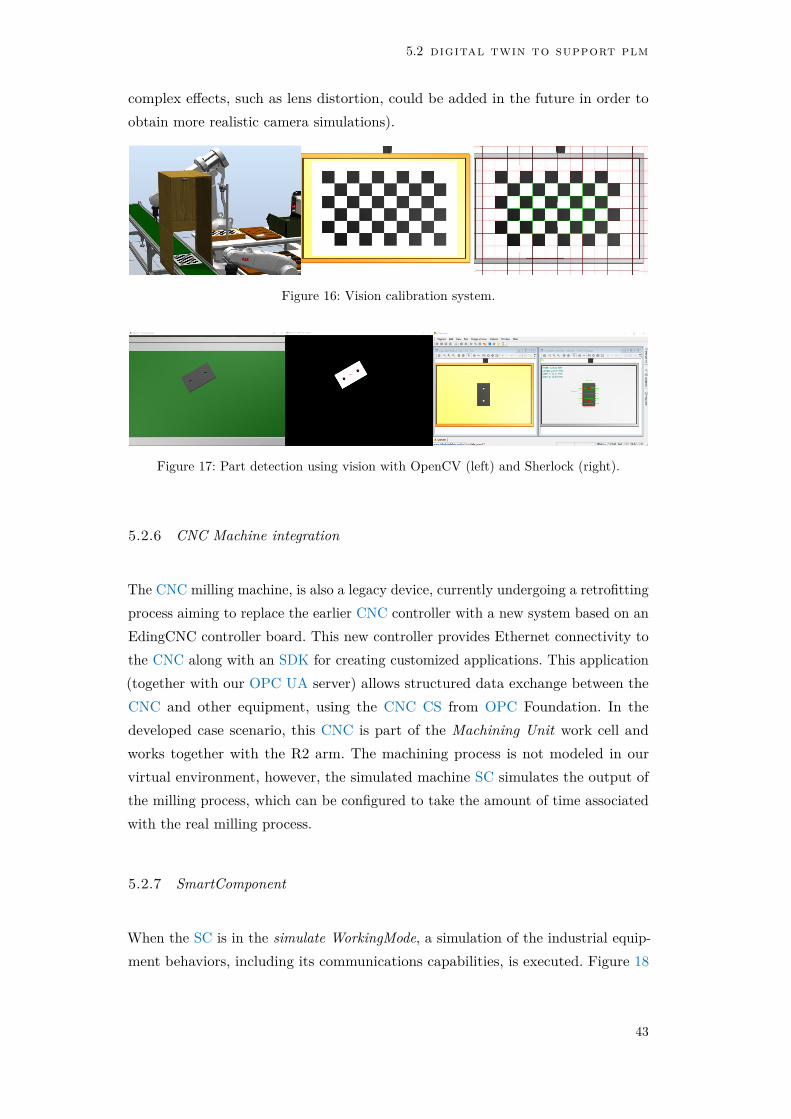
5.2 digital twin to support plm
complex effects, such as lens distortion, could be added in the future in order toobtain more realistic camera simulations).
Figure 16: Vision calibration system.
Figure 17: Part detection using vision with OpenCV (left) and Sherlock (right).
5.2.6 CNC Machine integration
The CNC milling machine, is also a legacy device, currently undergoing a retrofittingprocess aiming to replace the earlier CNC controller with a new system based on anEdingCNC controller board. This new controller provides Ethernet connectivity tothe CNC along with an SDK for creating customized applications. This application(together with our OPC UA server) allows structured data exchange between theCNC and other equipment, using the CNC CS from OPC Foundation. In thedeveloped case scenario, this CNC is part of the Machining Unit work cell andworks together with the R2 arm. The machining process is not modeled in ourvirtual environment, however, the simulated machine SC simulates the output ofthe milling process, which can be configured to take the amount of time associatedwith the real milling process.
5.2.7 SmartComponent
When the SC is in the simulate WorkingMode, a simulation of the industrial equip-ment behaviors, including its communications capabilities, is executed. Figure 18
43

tests and results
shows the RS simulation environment, as well as the UAExpert client that wasconnected to the simulated OPC UA server, showing the address space created bythe SC which describes the belt conveyor. The set of tests made in the simulatemode went according with the expected behaviour, obeying to the external ordersgiven by the OPC UA client and, at the same time, returning feedback from thesensors on the DT version of the belt conveyor.
Figure 18: Tests in simulate working mode.
When selected, and upon simulation start, the monitor WorkingMode createsan OPC UA client that connects to the real device’s OPC UA server. Among thetests made in monitor mode, the one from Figure 19, where a plastic part is carriedby the belt conveyor, is described here. The part was placed near the end of thebelt conveyor with equal position in the real equipment and in its DT, and thenthe real conveyor motion was started. During that motion the conveyor belt speedwas changed several times and, without any direct input feed, the DT followedthe speed variations according with the information of the rotary encoder madeavailable through the OPC UA server by the real conveyor. A video show-casingthese tests is available in the following link: https://youtu.be/n2sw55RcvHI.
A set of tests was developed to determine the performance of the DT, and toquantify the simulation computational needs for the given scenario, where five
44

5.2 digital twin to support plm
Power Supply
PLCNextDigital In/Out
Analog In/OutBelt
Conveyor
Part
DT
Figure 19: Tests in monitor working mode.
industrial robotic arms, two conveyors, two vision systems, a CNC milling machineand an automatic warehouse are working together to simulate a typical productionprocess. This evaluation was performed on a PC with Intel(R) Core(TM) i7-8550Uprocessor with four 1.8GHz CPU cores. Graphics are provided by a dedicatednVIDIA GeForce MX150 GPU with 1GB of memory. The PC has 12 GB of RAM,a 512 GB SSD, and is running an up to date Windows 10 64-bit.
Using the resource monitor while running the simulation process in RS in realtime, it was verified that all processes associated with RS have a small footprinton the CPU cores, with the largest component using up to 20% of a single core. Avideo obtained during these simulations is available in the following link: https://youtu.be/wLeMhhgLS5A.
45


6C O N C L U S I O N A N D F U T U R E W O R K
In this work, a virtual model of a typical production process with broader use throughthe complete lifecycle of an automated system was implemented, integrating bothrecent and legacy equipment. That virtualization scenario shows the feasibility ofthe DT of an industrial process using an existing simulation environment such as RS.In fact, RS was demonstrated to be a feature rich simulator, while supporting user-developed extensions through its SDK. From a subjective point of view, and in theauthor opinion, the learning curve and the programming effort using this softwareare comparably shorter than other popular simulators in the robotics field, such asGazebo and Tecnomatix Process Simulate. Additionally, the resources consumed bythe simulation, including the core simulation process and the additional user-definedfeatures running alongside, are perfectly suited to medium performance PCs.
For VC to become an adopted industry standard, the creation of reusable virtualmodels is a must. This work demonstrates how such models can be created withinthe RS environment, although the developed methodology could be applied to othersimulation environments. Even knowing that RS was developed mainly for offlineprogramming of ABB robots, this work shows that this software, together with itsSDKs, can be used in the different stages of the lifecycle of industrial equipment. Bymerging the capability of the ABB SDKs with the features of the OPC UA stackfrom OPC Foundation, together with the developed methodologies, a completelifecycle system was developed, integrating project, simulation and monitoring ofan industrial automation system, with real and simulation results being provided.It provides methodologies for integrating not just OPC UA enabled equipment, butalso both newly developed and legacy devices.
As this method of creating and implementing SCs relies on the RS SDK, developedby ABB, which is closed-source, there is some risk that future updates might breakthe API backward compatibility although, historically, that has not been a problem.Another potential difficulty with taking this route of combining RS SC and OPCUA is the need for a different set of skills for automation engineers, ranging fromrobot and PLC programming, to other programming languages and paradigms nottraditionally used in the field.
47

conclusion and future work
Regarding the integration of CNC machines, a methodology for the implemen-tation of an all-in-one monitoring solution was developed. Based on OPC UA,prioritizing the equipment interaction by means of a communication protocol, SDK,an API or simply the definition of a group of messages that can be exchangedwith the equipment. Additionally, the developed system can access the sensorsalready integrated, or externally added to the CNC machine, making the futureincorporation of other CNC machine models straightforward.
Given the variety of monitoring systems and communication protocols, multi-vendor solutions must take an approach where the various systems available onthe market are combined on a single system, allowing the data to be acquiredfrom a wider range of equipment in the industry. With the described approach,it was possible to fully integrate OPC UA within this simulation environment,benefiting from OPC UA’s structured approach, open platform characteristics andbuilt-in security. Given the growing acceptance within industry for OPC UA, and thecontinued release of standard information models (CS) in many industrial equipmentsectors, integrating additional equipment in the future should be easier. The mainproblem of OPC UA is the lack of well documented open source implementations.In fact, even the OPC Foundation’s own SDK, used in this development, which isviewed as a reference implementation, is scarcely documented, resulting in a steeplearning curve and increased development time.
The natural evolution of the laboratory test scenario is the inclusion of moredevices, both in the real world as well as the DT, and to improve the simulation towork seamlessly with real or simulated devices. We are also running experimentswith more real world CNC equipment and will have further data in the future.
Future work in this field will include data mining and machine learning techniquesin order to automatically detect and predict faults in order to perform predictivemaintenance on CNC machines.
Within the wider scope where this work is included, the interconnection of MESand ERP software with shop floor data supplied from our OPC UA Servers, isalso being developed, using KPIs (Key Performance Indicators) and OEE (OverallEquipment Effectiveness) metrics to determine efficiency and productivity of themachining processes. Here, the single OPC UA-based server interface plays animportant role in guaranteeing a common communication and data model for CNCmachines within a given company.
At the time of writing of this report the PubSub feature of OPC UA is not yetcertified due to the lack of official test cases and testing tools. Some advantages on
48
conclusion and future work
using this type of PubSub approaches can be stated compared with the traditionalserver-client used approach, namely the unnecessary traditional coupled server-clientparadigm and better scalability. In future developments of this work, after a fullytested and certified version of this OPC UA feature is made available, including itin the developed work might provide some benefits.
Recently, the Universal Machine Tool Interface (UMATI)1 working group wasestablished, in which OPC Foundation, the German machine tool builders associ-ation (VDW) and other industrial partners, are developing the OPC UA CS forMachine Tools. The aim is to develop an OPC UA information model as a universalcommunication interface for machine tools to "external" communication partnerssuch as MES, ERP, automation systems or the cloud, planned to be released inthe second half of this year2. Our developed methodology combines well with thosedevelopments. By adapting our interface with the resulting developments of thiswork group, we will guarantee that the systems based on our solution will work andsupport the integration, side-by-side, with future products that support this yet tobe defined standard.
1 https://opcfoundation.org/markets-collaboration/umati/2 https://opcua.vdma.org/en/viewer/-/v2article/render/47927388
49


B I B L I O G R A P H Y
Arjoni, Diego Hernandez et al. (2018). “Manufacture equipment retrofit to allowusage in the industry 4.0”. In: Proceedings - 2017 2nd International Conferenceon Cybernetics, Robotics and Control, CRC 2017. isbn: 9781538606773. doi:10.1109/CRC.2017.46.
Atluru, Sri H and A Deshpande (2009). “Data to Information: can MTconnectdeliver the promise”. In: 37th Annual North American Manufacturing ResearchConference (NAMRC 37). issn: 10473025.
Ayani, M., M. Ganebäck, and Amos H.C. Ng (2018). “Digital Twin: Applyingemulation for machine reconditioning”. In: Procedia CIRP. Vol. 72. ElsevierB.V., pp. 243–248. doi: 10.1016/j.procir.2018.03.139.
Ayatollahi, Iman et al. (2013). “Prototype OPC UA Server for Remote Control ofMachine Tools”. In: IN-TECH.
Bartodziej, Christoph Jan (2017). The Concept Industry 4.0 - An Empirical Analysisof Technologies and Applications in Production Logistics. Springer FachmedienWiesbaden. doi: 10.1007/978-3-658-16502-4.
Cavalieri, Salvatore, Marco Giuseppe Salafia, and Marco Stefano Scroppo (Jan.2019). “Integrating OPC UA with web technologies to enhance interoperability”.In: Computer Standards and Interfaces 61, pp. 45–64. issn: 09205489. doi:10.1016/j.csi.2018.04.004.
Cena, Gianluca, Adriano Valenzano, and Stefano Vitturi (Mar. 2008). “Hybridwired/wireless networks for real-time communications”. In: IEEE IndustrialElectronics Magazine 2.1, pp. 8–20. issn: 19324529. doi: 10.1109/MIE.2008.917155.
De Melo, Pablo Felipe Soares and Eduardo Paciencia Godoy (June 2019). “ControllerInterface for Industry 4.0 based on RAMI 4.0 and OPC UA”. In: 2019 IEEEInternational Workshop on Metrology for Industry 4.0 and IoT, MetroInd 4.0and IoT 2019 - Proceedings. Institute of Electrical and Electronics EngineersInc., pp. 229–234. isbn: 9781728104294. doi: 10.1109/METROI4.2019.8792837.
Downey, Jonathan, Sebastian Bombiński, et al. (2015). “Automatic multiple sensordata acquisition system in a real-time production environment”. In: ProcediaCIRP. Vol. 33. doi: 10.1016/j.procir.2015.06.039.
51

bibliography
Downey, Jonathan, Denis O’Sullivan, et al. (2016). “Real Time Monitoring of theCNC Process in a Production Environment- the Data Collection & AnalysisPhase”. In: Procedia CIRP. Vol. 41. doi: 10.1016/j.procir.2015.12.008.
Drahos, Peter et al. (Apr. 2018). “Trends in industrial communication and OPCUA”. In: Proceedings of the 29th International Conference on Cyberneticsand Informatics, K and I 2018. Vol. 2018-January. Institute of Electrical andElectronics Engineers Inc., pp. 1–5. isbn: 9781538644218. doi: 10.1109/CYBERI.2018.8337560.
Espressif (2019). ESP32-WROOM-32 Datasheet. Tech. rep. Espressif.Fanuc and Inventcom (2018). FANUC Open CNC API Specifications.Fernández, Igor Azkarate, Mikel Ayani Eguía, and Luka Eciolaza Echeverría (Sept.
2019). “Virtual commissioning of a robotic cell: An educational case study”.In: IEEE International Conference on Emerging Technologies and FactoryAutomation, ETFA. Vol. 2019-September. Institute of Electrical and ElectronicsEngineers Inc., pp. 820–825. isbn: 9781728103037. doi: 10.1109/ETFA.2019.8869373.
Forgó, Zoltán, Alfred Hypki, and Bernd Kuhlenkotter (2018). “Gesture based robotprogramming using ROS platform”. In: pp. 455–461.
Giessbauer, Reinhard et al. (2018). Global Digital Operations Study 2018 - Howindustry leaders build integrated operations ecosystems to deliver end-to-endcustomer solutions. PwC, pp. 1–64. isbn: 3315657866.
Gogolev, Alexander, Roland Braun, and Philipp Bauer (Jan. 2020). “TSN TrafficShaping for OPC UA Field Devices”. In: IEEE 17th International Conference onIndustrial Informatics (INDIN). Institute of Electrical and Electronics Engineers(IEEE), pp. 951–956. doi: 10.1109/indin41052.2019.8972252.
Grieves, Michael and John Vickers (Jan. 2016). “Digital twin: Mitigating unpre-dictable, undesirable emergent behavior in complex systems”. In: Transdis-ciplinary Perspectives on Complex Systems: New Findings and Approaches.Springer International Publishing, pp. 85–113. isbn: 9783319387567. doi: 10.1007/978-3-319-38756-7\_4.
Harrison, William S. and Frederick Proctor (2015). “Virtual Fusion: State of theArt in Component Simulation/Emulation for Manufacturing”. In: ProcediaManufacturing. doi: 10.1016/j.promfg.2015.09.069.
Hunkar, Paul (2014). OPC UA vs OPC Classic. Tech. rep. DSInteroperability.Imtiaz, Jahanzaib and Jurgen Jasperneite (2013). “Scalability of OPC-UA down to
the chip level enables "internet of Things"”. In: IEEE International Conferenceon Industrial Informatics (INDIN). isbn: 9781479907526. doi: 10.1109/INDIN.2013.6622935.
52
bibliography
Jbair, Mohammad et al. (May 2019). “Automatic PLC code generation basedon virtual engineering model”. In: Proceedings - 2019 IEEE InternationalConference on Industrial Cyber Physical Systems, ICPS 2019. Institute ofElectrical and Electronics Engineers Inc., pp. 675–680. isbn: 9781538685006.doi: 10.1109/ICPHYS.2019.8780213.
Khan, Adnan et al. (Dec. 2018). “Digital Twin for Legacy Systems: Simulation ModelTesting and Validation”. In: IEEE International Conference on AutomationScience and Engineering. Vol. 2018-August. IEEE Computer Society, pp. 421–426. isbn: 9781538635933. doi: 10.1109/COASE.2018.8560338.
Koenig, N. and A. Howard (2005). “Design and use paradigms for gazebo, anopen-source multi-robot simulator”. In: isbn: 0-7803-8463-6. doi: 10.1109/iros.2004.1389727.
Konstantinov, Sergey et al. (2017). “The Cyber-physical E-machine ManufacturingSystem: Virtual Engineering for Complete Lifecycle Support”. In: Procedia CIRP.Vol. 63. Elsevier B.V., pp. 119–124. doi: 10.1016/j.procir.2017.02.035.
Kritzinger, Werner et al. (Jan. 2018). “Digital Twin in manufacturing: A categoricalliterature review and classification”. In: IFAC-PapersOnLine 51.11, pp. 1016–1022. issn: 24058963. doi: 10.1016/j.ifacol.2018.08.474.
Liu, Chao et al. (Apr. 2019). “A Cyber-Physical Machine Tools Platform using OPCUA and MTConnect”. In: Journal of Manufacturing Systems 51, pp. 61–74.issn: 02786125. doi: 10.1016/j.jmsy.2019.04.006.
Lucas, João (2019). Desenvolvimento de servidor OPC UA para sistema CNC.Leiria.
Martins, Andre, Hugo Costelha, and Carlos Neves (Apr. 2020). “Supporting thedesign, commissioning and supervision of smart factory components throughtheir digital twin”. In: 2020 IEEE International Conference on AutonomousRobot Systems and Competitions, ICARSC 2020. Institute of Electrical andElectronics Engineers Inc., pp. 114–119. isbn: 9781728170787. doi: 10.1109/ICARSC49921.2020.9096072.
Martins, André, Hugo Costelha, and Carlos Neves (Apr. 2019). “Shop Floor Vir-tualization and Industry 4.0”. In: 19th IEEE International Conference onAutonomous Robot Systems and Competitions, ICARSC 2019. Institute ofElectrical and Electronics Engineers Inc. isbn: 9781728135588. doi: 10.1109/ICARSC.2019.8733657.
Martins, André, Hugo Costelha, Carlos Neves, and Luís Conde Bento (Oct. 2020a).CNCServer - Technical Manual. Tech. rep. Leiria: Polytechnic of Leiria.
— (Oct. 2020b). CNCServer - User Manual. Tech. rep. Leiria: Polytechnic ofLeiria.
53

bibliography
Martins, André, João Lucas, et al. (Nov. 2020). “Developing an OPC UA Server forCNC Machines”. In: 2020 International Conference on Industry 4.0 and SmartManufacturing.
Mourtzis, Dimitris, Nikolaos Milas, and Nikolaos Athinaios (Jan. 2018). “TowardsMachine Shop 4.0: A General Machine Model for CNC machine-tools throughOPC-UA”. In: Procedia CIRP. Vol. 78. Elsevier B.V., pp. 301–306. isbn:9781510875692. doi: 10.1016/j.procir.2018.09.045.
Neu, Charles Varlei, Ina Schiering, and Avelino Zorzo (Nov. 2019). “Simulatingand detecting attacks of untrusted clients in OPC UA networks”. In: ACMInternational Conference Proceeding Series. New York, New York, USA: Associ-ation for Computing Machinery, pp. 1–6. isbn: 9781450372961. doi: 10.1145/3360664.3360675.
Neves, Carlos, Hugo Costelha, and Luís Bento (2018). “Indústria 4.0 - A quartarevolução industrial”. In: O Molde nº118.
OPC Foundation (2018). OPC UA Specification Part 14 - PubSub 1.04.Pitonakova, Lenka et al. (July 2018). “Feature and Performance Comparison of the
V-REP, Gazebo and ARGoS Robot Simulators”. In: Springer, Cham, pp. 357–368. doi: 10.1007/978-3-319-96728-8\_30.
René de Jesús, Romero Troncoso et al. (2003). “Driver current analysis for sensorlesstool breakage monitoring of CNC milling machines”. In: International Journalof Machine Tools and Manufacture 43.15. issn: 08906955. doi: 10.1016/j.ijmachtools.2003.08.004.
Riera, B. and B. Vigário (July 2017). “HOME I/O and FACTORY I/O: a virtualhouse and a virtual plant for control education”. In: IFAC-PapersOnLine 50.1,pp. 9144–9149. issn: 24058963. doi: 10.1016/j.ifacol.2017.08.1719.
Sicherheit in der Informaationstechnik, Bundesamt für (2017). OPC UA SecurityAnalysis. Tech. rep. für Sicherheit in der Informaationstechnik, Bundesamt.
Smid, P (2005). Fanuc CNC Custom Macros: Programming Resources for FanucCustom Macro B Users. Industrial Press, pp. 267–274.
Staranowicz, Aaron and Gian Luca Mariottini (2011). “A survey and comparison ofcommercial and open-source robotic simulator software”. In: Proceedings of the4th International Conference on PErvasive Technologies Related to AssistiveEnvironments - PETRA ’11. New York, New York, USA: ACM Press, p. 1.isbn: 9781450307727. doi: 10.1145/2141622.2141689.
Stavropoulos, P. et al. (2016). “Tool wear predictability estimation in milling basedon multi-sensorial data”. In: International Journal of Advanced ManufacturingTechnology 82.1-4. issn: 14333015. doi: 10.1007/s00170-015-7317-6.
54
bibliography
Straus, Patrick et al. (Dec. 2018). “Enabling of Predictive Maintenance in the Brown-field through Low-Cost Sensors, an IIoT-Architecture and Machine Learning”. In:2018 IEEE International Conference on Big Data (Big Data). IEEE, pp. 1474–1483. isbn: 978-1-5386-5035-6. doi: 10.1109/BigData.2018.8622076.
Tao, Fei, Qinglin Qi, et al. (Aug. 2019). “Digital Twins and Cyber–Physical Systemstoward Smart Manufacturing and Industry 4.0: Correlation and Comparison”.In: Engineering 5.4, pp. 653–661. issn: 20958099. doi: 10.1016/j.eng.2019.01.014.
Tao, Fei and Meng Zhang (2017). “Digital Twin Shop-Floor: A New Shop-FloorParadigm Towards Smart Manufacturing”. In: IEEE Access 5, pp. 20418–20427.issn: 2169-3536. doi: 10.1109/ACCESS.2017.2756069.
Underberg, Lisa et al. (June 2018). “Towards hybrid wired-wireless networks inindustrial applications”. In: Proceedings - 2018 IEEE Industrial Cyber-PhysicalSystems, ICPS 2018. Institute of Electrical and Electronics Engineers Inc.,pp. 768–773. isbn: 9781538665312. doi: 10.1109/ICPHYS.2018.8390804.
VDMA and OPC Foundation (2019a). OPC UA Companion Specification forMachine Vision. Tech. rep. VDMA and OPC Foundation.
— (2019b). OPC UA Companion Specification for Robotics. Tech. rep. VDMA andOPC Foundation.
VDMA and Fraunhofer IOSB-INA (2017). Industrie 4.0 Communication GuidelineBased on OPC UA. Tech. rep. VDMA, Fraunhofer IOSB-INA.
VDW and OPC Foundation (2017). OPC UA Companion Specification for CNCSystems. Tech. rep. VDW and OPC Foundation.
Vrabič, Rok et al. (2018). “Digital twins: Understanding the added value of integratedmodels for through-life engineering services”. In: Procedia Manufacturing. issn:23519789. doi: 10.1016/j.promfg.2018.10.167.
Zhong, Ray Y. et al. (2017). “Intelligent Manufacturing in the Context of Industry4.0: A Review”. In: Engineering. issn: 20958099. doi: 10.1016/J.ENG.2017.05.015.
55