positioning, navigation and awareness of the vamos
TRANSCRIPT

Positioning, Navigation and Awareness of the ¡VAMOS! Underwater
Robotic Mining System
J. Almeida1, A. Martins1, C. Almeida2, A. Dias1, B. Matias2, A. Ferreira2, P. Jorge2, R. Martins2, M. Bleier3
A. Nuchter4, J. Pidgeon5, S. Kapusniak6 and E. Silva1
Abstract— This paper presents the positioning, navigationand awareness (PNA) system developed for the UnderwaterRobotic Mining System of the ¡VAMOS! project [1]. It describesthe main components of the ¡VAMOS! system, the PNA sensorsin each of those components, the global architecture of the PNAsystem, and its main subsystems: Position and Navigation, Real-time Mine Modeling, 3D Virtual reality HMI and Real-timegrade system. General results and lessons learn during the firstmining field trial in Lee Moor, Devon, UK during the monthsof September and October 2017 are presented.
I. INTRODUCTION
Europe estimates that the value of unexploited European
mineral resources at depth of 500 - 1000 meters is approxi-
mately e 100 billion, and the European Union consumes 25-
30% of the world’s metal production [2]. Despite the efforts
to develop recycling technologies and material science, the
EU’s industry dependency on metal imports is growing every
year (200 million tons of minerals), in which 14 mineral raw
materials were explicitly named as highly critical for the
industry [3]. In answer to this European concern a research
and innovation action program was created regarding the de-
velopment of new technology for automated mining, mining
of small deposits and also alternative mining methods [4].
One of these projects is ¡VAMOS! , that stands for Viable
Alternative Mine Operating System, funded by the European
Unions Horizon 2020 research and innovation programme,
addresses the development of a prototype underwater min-
ing system to extract raw materials from flooded open-pit
mines. These inland mines have been considered depleted
in the past because with previous mining techniques it was
not economically viable anymore to continue operations.
Today, with rising prices of certain rare ores it becomes
interesting again to re-open abandoned mines in order to
access deeper seated minerals. However, conventional mining
techniques require high treatment and dewatering costs.
1INESC Technology and Science, ISEP - School of Engineer-ing, Porto, Portugal jose.m.almeida, alfredo.martins,andre.dias, [email protected]
2INESC Technology and Science, Porto, Portugalcarlos.almeida, blmatias, antonio.b.ferreira,pedro.jorge, [email protected]
3Zentrum fur Telematik e.V., Wurzburg, [email protected]
4Informatics VII Robotics and Telematics, Julius Maximilian Univer-sity of Wurzburg and Zentrum fur Telematik e. V., Wurzburg, [email protected]
5BMT WBM Pty Ltd, Brisbane, [email protected]
6Soil Machine Dynamics, Newcastle-Upon Tyne, United [email protected]
Fig. 1. H2020 ¡VAMOS! project concept.
Moreover, from an environmental perspective, it is desirable
that the water table of these flooded inland mines is not
changed. Therefore, the ¡VAMOS! project aims to develop a
new remotely controlled underwater mining machine (MV),
associated launch and recovery vessel (LARV) and support
and survey autonomous/remote operated underwater vehicle
(AUV/HROV), which provides a mining technique that is
environmentally and economically more viable than the state-
of-the-art [5], [6].
The challenge in tele-operating a large underwater min-
ing vehicle is that there is no direct inter-visibility, which
makes precise control difficult. For the proper and efficient
operation of the ¡VAMOS! Underwater mining system, the
operators in a remote control cabin (CC) at the surface,
cannot rely only on raw data streams from the sensors on
the MV, LARV and the EVA AUV/HROV, and must have all
the perception and localization sensors data fused, integrated,
and presented in a user friendly and intuitive virtual reality
environment.
For that, all navigation sensors are combined and fused
to provide real-time, accurate and precise information about
the localization and orientation/attitude of all ¡VAMOS!
systems (MV, LARV and EVA AUV/HROV). This real-time
navigation information and the mine perception data from
multibeam, 3D sonar and structured light systems, feed the
3D mine modeling system [7] [8] [9] that updates the 3D
model both with real-time data and with off-line survey data
from the EVA AUV. The 3D mine model, navigation data
and sensor data, feed the Virtual Reality interface providing
operators friendly 3D visualization of mine and all the
¡VAMOS! vehicles, as well as, the overlay of sensor data
and mining operation information.
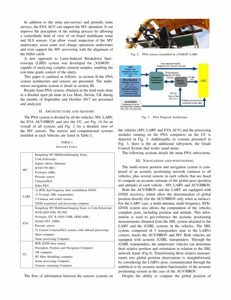
In addition to the mine pre-surveys and periodic mine
surveys, the EVA AUV can support the MV operation. It can
improve the perception of the mining process by allowing
a controllable field of view of on board multibeam sonar
and SLS sensors. Can allow visual inspection of the MV
underwater, assist some tool change operations underwater
and even support the MV recovering with the alignment of
the bullet catch.
A new approach to Laser-Induced Breakdown Spec-
troscopy (LIBS) system was developed for ¡VAMOS! ,
capable of analyzing complex mineral samples, enabling the
real-time grade control of the slurry.
This paper is outlined as follows: in section II the PNA
system architecture and sensors are presented. The multi-
sensor navigation system is detail in section III,
Results from PNA system, obtained in the field trials done
in a flooded open pit mine in Lee More, Devon, UK during
the months of September and October 2017 are presented
and analyzed.
II. ARCHITECTURE AND SENSORS
The PNA system is divided by all the vehicles: MV, LARV,
the EVA AUV/HROV and also the CC, see Fig. 14 for an
overall of all systems and Fig. 2 for a detailed view of
the MV sensors. The sensors and computational systems
installed in each Vehicles are listed in Table I.
TABLE I
SENSORS TABLE
MV
Kongsberg M3 Multibeam/Imaging Sonar;
Coda Echoscope;
Impact subsea Altimeter;
KVH1750 IMU;
Evologics uSBL;
Pressure sensor;
Cameras/SLS;
Sidus P&T.
LARV
3x RTK dual frequency dual constellation GNSS;
3x Evologic SBL transponders;
5 Cameras and winch sensors;
GNSS acquisition and processing computer.
EVA
Kongsberg M3 Multibeam/imaging Sonar or Coda Echoscope;
KVH GEO FOG 3D INS;
Evologics S2C R 42/65 USBL OEM uSBL;
Nortek DVL 1MHz;
Pressure sensor;
3x Custom Cameras/SLS systems with onboard processing;
Main computer;
Sonar processing Computer.
CC
RTK GNSS base station;
Perception, Position and Navigation Computer;
VR computer;
RT Mine Modelling computer;
Sonar processing Computer;
Cameras streaming Computer.
The flow of information between the sensors systems on
Fig. 2. PNA sensors assembled in ¡VAMOS! LARV.
Fig. 3. PNA Proposed Architecture
the vehicles (MV, LARV and EVA AUV) and the processing
modules running on the PNA computers on the CC is
depicted in Fig. 3. Additionally, to systems presented in
Fig. 3, there is the an additional subsystem, the Grade
Control System that works stand alone.
The following sections details the main PNA subsystems.
III. NAVIGATION AND POSITIONING
The multi-sensor position and navigation system is com-
posed of an acoustic positioning network common to all
vehicles, plus several sensors in each vehicle that are fused
to compute an accurate estimate of the global pose (position
and attitude) of each vehicle - MV, LARV and AUV/HROV.
Both the AUV/HROV and the LARV are equipped with
GNSS receivers, which allow the determination of global
position directly (for the AUV/HROV only when at surface).
For the LARV case, a multi-antenna, multi-frequency, RTK-
GNSS system also allows the computation of the vehicles
complete pose, including position and attitude. This infor-
mation is used to geo-reference the acoustic positioning
measurements obtained from the SBL system attached to the
LARV and the iUSBL systems in the vehicles. The SBL
system, composed of 3 transponders near to the LARVs
corners, tracks the AUV/HROV and MV. Both vehicles are
equipped with acoustic iUSBL transponders. Through the
iUSBL transponders, the underwater vehicles can determine
their relative position and orientation in relation to the SBL
network frame (Fig.4). Transforming these relative measure-
ments into global position observations is straightforward,
by considering the LARVs pose, communicated through the
umbilical or by acoustic modem functionality of the acoustic
positioning system in the case of the AUV/HROV.
Despite the ability to compute the global position of

Fig. 4. ¡VAMOS! Underwater Position System.
Fig. 5. Functional architecture of localization system
all vehicles with only the SBL/iUSBL and LARV GNSSs,
the integration/fusion of all other sources of information
is mandatory to increase the robustness of the solution.
Robustness is improved by catering for multi-paths acoustics
(due to the enclosed environment). The fusion with the
other information sources also allows an increase in the
estimation rate, reduction of the estimate uncertainty and
estimation of additional pose states such as attitude and ve-
locity. Therefore, the underwater vehicles carry extra sensors,
whose measurements are fused with the information from the
acoustic positioning system. The AUV/HROV carries an INS
unit, integrating a triaxial accelerometers, FOG gyroscopes
and magnetometers as well as a dual frequency triple con-
stellation GNSS receiver. There is also a DVL system for
measuring the linear velocities relative to the mine bottom,
when close to it, or to the water column. DVL sensors
produce direct observation of linear velocity, as opposed to
the INS system that determines linear velocity by integration
of measured accelerations. This causes the INS velocities to
drift with time, unlike the DVL case, for which a bounded
error is expected. Nevertheless, DVL alone does not fully
replace an INS, as it does not provide information about the
vehicle attitude. Moreover, the INS provides measurements
at a fix rate, while the DVL is subjected to dropouts resulting
from noise, multi-path or loss of range. For that reason,
the integration of INS and DVL is advantageous, as they
complement each other. A pressure sensor gives an indication
of the vehicles depth underwater. The MV carries a fibre
optic gyros (FOG) based IMU (KVH 1750 mounted in a turn
table mechanism for initial bias estimation and north seeking
[10]), from which the vehicles attitude is determined. A
pressure sensor allows the direct determination of the vertical
position with respect to the surface. Global positioning is
obtained from the acoustic positioning system. An Extended
Kalman Filter, independent for each vehicle, is responsible
for fusing all sensor information to compute their full pose
in real time (Fig.5).
This real time navigation solution and all of the point
cloud data streams from the Multi-beam profilers, 3D Sonars,
and SLS systems feed the continuous-time SLAM and mine
modeling software.
IV. REAL TIME MINING MODEL
In the ¡VAMOS! project one important component to
enhance situational awareness of the operator is the real
time mining modeling system since it is well known that
a map of the environment in addition to the raw sensor
data is extremely helpful in supporting remote control and
enhancing spatial awareness. In order to achieve this, the
real time mining modeling system fuses measurements from
the perception sensor systems, such as multi-beam sonar, 3D
imaging sonar, and structured light scanners, into a consistent
3D representation. Mapping algorithms based on a signed
distance function (SDF) voxel map and sensor models were
developed to integrate measurements taken with varying
accuracy and noise properties. In order to store large maps
with low memory consumption we need to encode free space
efficiently. To do this we store the SDF voxel map in an
tree structure. We integrate the different sensor modalities by
following the generalized sensor fusion approach proposed
by [11]. A SDF map is a beneficial surface representation
because noisy measurements are smoothed over multiple
observations. Starting with a pre-mining site survey the 3D
environment model is updated online during operations. As
the mine changes over time, due to the mining operations
themselves the internal representation of the mining environ-
ment needs to be constantly updated based on new sensor
observations. Since most of the model representing the mine
does not change, only small volumes need to be updated
frequently.
The resulting 3D terrain map is presented in a virtual
reality to the operator via the ¡VAMOS! Human Machine
Interface described in the following section. In Fig. 6, in
the virtual reality system. The mapped volume has a size of
roughly 1000m x 1000m x 150m. For visualization purposes
the map was reduced to 10cm resolution for the above-the-
water terrain mesh. Below the water surface the data was
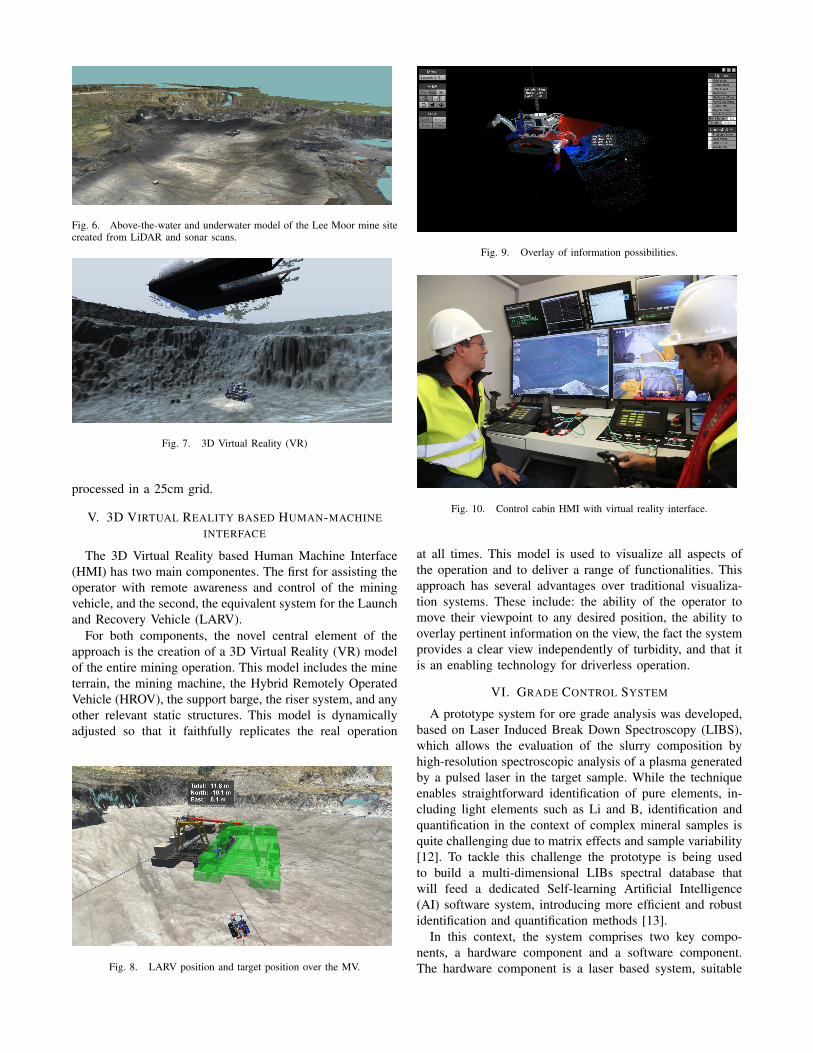
Fig. 6. Above-the-water and underwater model of the Lee Moor mine sitecreated from LiDAR and sonar scans.
Fig. 7. 3D Virtual Reality (VR)
processed in a 25cm grid.
V. 3D VIRTUAL REALITY BASED HUMAN-MACHINE
INTERFACE
The 3D Virtual Reality based Human Machine Interface
(HMI) has two main componentes. The first for assisting the
operator with remote awareness and control of the mining
vehicle, and the second, the equivalent system for the Launch
and Recovery Vehicle (LARV).
For both components, the novel central element of the
approach is the creation of a 3D Virtual Reality (VR) model
of the entire mining operation. This model includes the mine
terrain, the mining machine, the Hybrid Remotely Operated
Vehicle (HROV), the support barge, the riser system, and any
other relevant static structures. This model is dynamically
adjusted so that it faithfully replicates the real operation
Fig. 8. LARV position and target position over the MV.
Fig. 9. Overlay of information possibilities.
Fig. 10. Control cabin HMI with virtual reality interface.
at all times. This model is used to visualize all aspects of
the operation and to deliver a range of functionalities. This
approach has several advantages over traditional visualiza-
tion systems. These include: the ability of the operator to
move their viewpoint to any desired position, the ability to
overlay pertinent information on the view, the fact the system
provides a clear view independently of turbidity, and that it
is an enabling technology for driverless operation.
VI. GRADE CONTROL SYSTEM
A prototype system for ore grade analysis was developed,
based on Laser Induced Break Down Spectroscopy (LIBS),
which allows the evaluation of the slurry composition by
high-resolution spectroscopic analysis of a plasma generated
by a pulsed laser in the target sample. While the technique
enables straightforward identification of pure elements, in-
cluding light elements such as Li and B, identification and
quantification in the context of complex mineral samples is
quite challenging due to matrix effects and sample variability
[12]. To tackle this challenge the prototype is being used
to build a multi-dimensional LIBs spectral database that
will feed a dedicated Self-learning Artificial Intelligence
(AI) software system, introducing more efficient and robust
identification and quantification methods [13].
In this context, the system comprises two key compo-
nents, a hardware component and a software component.
The hardware component is a laser based system, suitable

Fig. 11. Architecture of the LIBS system.
Fig. 12. Example of mineral sample from the Database (Lithium ore),with composition mapping from the LIBS spectra, and reference analysissystems
for plasma spectroscopy analysis of the slurry composition,
assisted by high resolution fibre optic spectrometer, including
a low cost UV-Vis analysis system. The software component
is a dedicated Firmware for implementation of a LIBS AI
system, coupled with a big Data Geological database (LIBs,
UV-Vis-NIR spectra, and other analytic standards) built with
geological reference materials, pure minerals and mining
samples. The modular nature of the hardware, combined
with the innovative nature of te signal processing approach
enabled a Smart Libs technology that can perform in different
environments. The system was first set up in the Lab to build
a mineral spectra Database, with several samples of pure
and complex minerals (Fig 12), of interest to the mining
operations.
VII. FIELD RESULTS
Integrated ¡VAMOS! system field trials were performed
at the Lee Moor china clay mine (Fig. 13) in Devon, UK.
This was a complex setup involving logistics of 15 container
transport trucks and construction works. The PNA test period
spanned a period of almost two months and involved both
the on-site setup, calibration and evaluation.
A pre-survey of the open pit was performed in 4 missions
of the EVA AUV, trajectories are depicted in Fig 15. This
information was integrated in the mine model used in the
virtual reality human-machine interface (Fig. 7). The position
and attitude of the the vehicles calculated by the PNA and
integrated in the VR system, allowed for precise sensor
information fusion and efficient vehicle control. The VR
Fig. 13. Lee More, Devon, UK Field Tests.
Fig. 14. ¡VAMOS! Developed Systems.
interface integrated information from the multiple vehicles in
the operation in a consistent interface (Fig. 16) and was also
seamless integrated with other conventional command and
control interfaces in the CC. During the tests one of the major
findings was the high level of usability of the system both by
MV trained operators and non trained personal. Multibeam
sonar data in imaging mode was used not only to provide
awareness in very restricted visibility conditions (see Fig. 19
and Fig. 18) but also in profiling mode (Fig. 17) for cutting
volume assessment.
The LIBS system prototype (Fig 20) was put into operation
at the mine site in Lee Moor. Different types of samples,
Fig. 15. Pre-Survey bathymetry missions with EVA AUV.

Fig. 16. M3 Scanning of 3 MV Cuts.
Fig. 17. Boom cutter multibeam sonar modeling.
including Kaolin, granite and other rocks, were collected
on site, from the slurry output, from different points of
the dewatering station, and from the mouth of the Mining
Vehicle. All were analyzed on site and compared against the
reference Database.
The system was able to classify very clearly the different
types of Kaolin and granites (Fig. 21). An unknown black
sample was also standing out in the data classification. By
running the collected spectra against the reference database
the AI software was able to identify the sample as a Tour-
maline mineral containing Lithium. These results were later
confirmed by the mine geochemical reports and geologists.
VIII. CONCLUSIONS
The ¡VAMOS! system development was the first time
that an innovative robotic system comprising underwater
Fig. 18. Boom cutter sonar imaging.
Fig. 19. Lee More Water turbidity.
Fig. 20. LIBS system prototype in operation at Lee Moor field trials.
mining vehicle, support AUV, launch and recovery vessel
and associated equipment was deployed and integrated in a
real flooded pit mine with mining operation.
The Position, Navigation and Awareness system of the
¡VAMOS! robotic system was thus developed, integrated
and validated in real operational conditions. The process
of integration and setup of all the PNA equipment in the
multiple ¡VAMOS! vehicles and CC was a complex engi-
neering process, involving various engineering teams and
addressing mechanical; hardware; software and communica-
tions aspects. This process of configuration, parametrization
and calibration of a vast number of subsystems in multiple
assets toke around 2 to 3 weeks.
From the trials it was evident that the PNA is critical
for the operation of the mining system. It was possible to
have the position of the vehicles, map and perceive the
environment and how it changed with the mining process.
The EVA AUV/HROV was easy to deploy, capable to do
both the pre-surveys of the mine pit and also in assisting the
mine process operation, providing external viewpoints of the
MV environment.
The 3D mine modeling process was able to fuse the
multibeam sonars (from multiple vehicles) information with
the associated position and navigation data into models used
to feed the VR framework.

Fig. 21. Classification of the different samples collected and characterizedat Lee Moor according to the features of their LIBS spectra.
During field trials the VR HMI shown to be a very
powerful tool, providing the operator with an enhance-
ment awareness of all the ¡VAMOS! elements (MV, LARV,
AUV/HROV) and of the environment allowing a better con-
trol of the mining process. It was able to handle articulable
models of the mobile machines, the mine environment,
update all models with the real-time data from position and
all articulations, add overlays of useful information for the
operator, and the real-time terrain modeling.
The LIBS System usefulness was demonstrated in the field
trials although not deployed underwater in the MV. LIBS
was able to identify targets in a complex scenario, as long as
proper training with reference materials from the target mine
is performed. The results show the viability of using LIBS
as an ore grading tool. Next steps of development include
hardware improvements to enable operation underwater or
directly in the slurry pipe. Such solutions are at reach using
for instance sampling probes with compressed air and using
double pulse lasers techniques [14] [15].
The testing, validation and benchmarking of the structured
light systems and their impact on the perception and aware-
ness process was not possible to be done at Lee Moor due to
the site specific conditions, namely the high level of fine silt
(from china clay) causing extreme water turbidity. Despite
the high number of suspended particles in the water there
was very limited impact on the sonar data, only with a small
decrease on the DVL effective range due to soft ground and
reduced reflections.
In the next field trials to occur in the Vares mine in Bosnia
the SLS system is to be validated. This is a mine with a much
hard rock producing very different water turbidity conditions.
Ongoing work is been pursued in the automation of the
PNA initial setup and calibration procedures in order improve
the global process efficiency.
The planned field trials in the new site will allow for the
test of the system in different operational conditions, namely
with higher depths, different pit conditions and different set
of minerals on the walls and bottom of the pit. The gathered
added information will also allow for a more complete
characterization of the performance of the developed system
and to evaluate the impact of the PNA in mining production
process.
ACKNOWLEDGEMENT
This work was funded by the VAMOS project funded
by the European Commission under the H2020 EU Frame-
work Programme for Research and Innovation (H2020-SC5-
2014, 642477) and by project CORAL- Sustainable Ocean
Exploitation: Tools and Sensors (reference NORTE-01-0145-
FEDER-000036), supported by North Portugal Regional Op-
erational Programme (NORTE 2020), under the PORTUGAL
2020 Partnership Agreement, through the European Regional
Development Fund (ERDF)
REFERENCES
[1] !VAMOS. Viable alternative mine operating system. Available athttp://vamos-project.eu/.
[2] Strategic Implementation Plan for the European Innovation Partnershipon Raw Materials, Sept, 2013.
[3] Critical raw materials for the eu. Available athttps://ec.europa.eu/docsroom/documents/10010/attachments/1/translations/en/renditions/pdf.
[4] European innovation partnership on raw materials. Available athttps://ec.europa.eu/eip/raw-materials/en/content/eip-targets.
[5] J. Johansson L. Abrahamsson, B. Johansson. Future of metal mining:Sixteen predictions. International Journal of Mining and Mineral
Engineering, 1(1):304–312, 2009.[6] Jennifer MDurden, David SMBillett, Alastair Brown, Andrew CDale,
Laura Goulding, Sabine Gollner, Kevin Murphy, Ellen Pape, Au-tun Purser, Jean-Francois Rolin, Austin JSmith, Ian Stewart, PhillipJTurner, Tom de Wachter, Philip PEWeaver, Cindy Lvan Dover,Philomene Verlaan, and Daniel OBJones. Report on the managingimpacts of deep-sea resource exploitation (midas) workshop on en-vironmental management of deep-sea mining. Research Ideas and
Outcomes, 2:e10292, 2016.[7] Michael Bleier, Andr Dias, Antnio Ferreira, John Pidgeon, Jos
Almeida, Eduardo Silva, Klaus Schilling, and Andreas Nchter. Signeddistance function based surface reconstruction of a submerged inlandmine using continuous-time slam. IFAC-PapersOnLine, 50(1):1139 –1144, 2017. 20th IFAC World Congress.
[8] A. Ferreira J. Pidgeon J. Almeida E. Silva K. Schilling M. Bleier,A. Dias and A. Nchter. Real-time 3d mine modelling in the vamos!project. In Real Time Mining Conference, 2017.
[9] J. Almeida, A. Ferreira, B. Matias, A. Dias, A. Martins, F. Silva,J. Oliveira, P. Sousa, M. Moreira, T. Miranda, C. Almeida, andE. Silva. Air and underwater survey of water enclosed spaces forvamos! project. In OCEANS 2016 MTS/IEEE Monterey, pages 1–5,Sept 2016.
[10] A. Albrecht and J. Petereit. Application of an off-the-shelf fiber opticgyroscope based inertial measurement unit for attitude and headingestimation. In 2017 IEEE SENSORS, pages 1–3, Oct 2017.
[11] Stefan May, Philipp Koch, Rainer Koch, Christian Merkl, ChristianPfitzner, and Andreas Nuchter. A generalized 2D and 3D multi-sensordata integration approach based on signed distance functions for multi-modal robotic mapping. In 19th Int. Workshop on Vision, Modeling
and Visualization, pages 95–102, 2014.[12] et al. Harmon R.S. pplications of laser-induced breakdown spec-
troscopy for geochemical and environmental analysis: A comprehen-sive review. In Spectrochimica Acta, volume 87, pages 11–26, 2013.
[13] Patent: PCT/IB2017/056039. The system here referred is protectedby an international patent application(pct/ib2017/056039) and twoeuropean patents that are in preparation comprising the elementsreported in the inesc tec’s invention disclosure number ci 18-0265.
[14] J. Guo et. al. A review of laser-induced breakdown spectroscopyfor analysis of geological materials. Applied Spectroscopy reviews,50(1):1–26, 2015.
[15] B. Thornton et al. Development of a deep-sea laser induced breakdownspectrometer fo in-situ multi-element chemical analysis. Deep-Sea
Research I, 95:20–36, 2015.