posltive gaging system feasibility study
TRANSCRIPT

POSlTiVE GAGING SYSTEM
FEASIBILITY STUDY
l NTER l M REPORT
PERIOD, May 15, 1967 t o November 15, 1967
C o n t r a c t No. NAS 9-6751
Prepared f o r
NASA - MANNED SPACECRAFT CENTER Houston, Texas
THE BENDIX CORPORATION INSTRUMENTS & L IFE SUPPORT DIVISION
Davenport , l owa
PUBLICATION NO, 3914.1-68-1 February 15, I968

B&ndixs Instruments & *ey&2 L i f e Support Division
SECT l ON
FORWARD
ABSTRACT
SECTION I
SECTION I I
SECTION I l l
3.1
3 . 2
3.3
3 .3 .1
3 . 3 . 2
3 . 4
3.5
3 . 6
3 .6 .1
SECTION IV
4.1
4 . 2
4 .2 .1
4 . 2 - 2
4 . 2 . 3
4 . 2 . 4
4 . 3
4 .3 .1
4 . 3 . 2
4 - 4
4 .4 .1
4 . 4 . 2
4 . 5
4 . 5 . 1
4 . 5 . 2
TABLE OF CONTENTS
INTRODUCTION
PROGRAM OBJ ECT l V ES
THEORETICAL STUDIES
INTRODUCTION
PROPELLANT TANKS AND FUELS STUDIED
PROPELLANT PROPERTIES STUDY
LITERATURE SEARCH
ELECTRICAL PROPERTIES AS A FUNCTION OF FREQUENCY AND TEMPERATURE
SIMULATION OF ELECTRICAL PROPERTIES OF PROPELLANTS
METHODS OF MEASUREMENT OF DIELECTRIC CONSTANT AND LOSS TANGENT
TECHN l QUE A THEORY
TECHNIQUE B THEORY
TECHNIQUE C THEORY
PREDICTED SYSTEM RESPONSE
EXPER l MENTAL STUD l ES
I NTRODUCT l ON
DIELECTRIC PROPERTIES OF PROPELLANTS
RESONANT CAVITY METHOD - PURE FLUIDS
RESONANT CAVITY METHOD - DILUTED FLUIDS
VON H l PPEL METHOD
DIELECTRIC PROPERTIES OF BLADDER MATERIAL
TECHNIQUE A EXPERIMENTATION
TESTS CONDUCTED
DISCUSSION
TECHNIQUE B
TESTS CONDUCTED
DISCUSSION
TECHNIQUE C
TESTS CONDUCTED
DISCUSSION
PAGE NUMBER
I
i i
I - /
2- 1

Instruments & l i f e Support Division
TABLE OF CONTENTS
SECT l ON
SECTION V
5. I
5 . 2
5 . 2 . 1
5 . 2 . 2
5 . 2 . 3
5 . 3
5 .3 .1
5 . 3 . 2
5 . 3 . 3
5 . 3 . 4
5 . 3 . 5
SECTION V I
SECTION V I I
7 . 1
7 . 2
SECTION V I I I
IMPLEMENTATION OF THE RF TECHNIQUE
INTRODUCTION
SYSTEM CHARACTERISTICS OF RF GAGING TECHNIQUES
TECHNIQUE A
TECHNIQUE C
TECHN I QUE B
COMPONENT CHARACTERISTICS
RF OSCILLATOR AND SWEEP GENERATOR
R F CABLES
C l RCU LATOR
PROBES
R F S IGNAL DETECTOR
CONCLUSIONS
RECOMMENDATIONS
INTRODUCTION
HARDWARE DEVELOPMENT PROGRAM
REFERENCES
PAGE NUMBER

Be~ld i :~ Instruments (k -4: Life Support Division
L IST OF FIGURES
F i GURE NUMBER PAGE NUMBER
3- 1 SIMULATED STORAGE TANK 3-2
3 - 2 I D E A L I Z E D E ' VERSUS FREQUENCY GRAPH FOR A NON-POLAR TRANSPARENT MATERIAL 3-6
3 - 3 I D E A L I Z E D E ' VERSUS FREQUENCY GRAPH FOR A POLAR TRANSPARENT MATERIAL
3 - 4 D I E L E C T R I C MEASUREMENT US ING RESONANT C A V I T Y AND TRANSMITTED POWER TECHNIQUE 3 - I 2
3 - 5 D I E L E C T R I C MEASUREMENT US ING RESONANT C A V I T Y AND REFLECTED POWER TECHNIQUE
3-6 APPARATUS FOR ROBERTS-VON H I P P E L METHOD
3 - 7 T E O l l MODE RESONANT STRUCTURE FOR D I E L E C T R I C MEASUREMENT 3 - 2 0
3-8 F I E L D S OF T E O I 1 MODE I N R IGHT CIRCULAR CYLINDER 3-22
3-9 C Y L I N D R I C A L RESONATOR COORDINATES 3 - 2 3
3-10 P A R T I A L L Y F I L L E D CYLINDER
3-1 1 P A R T I A L L Y F I L L E D RECTANGULAR C A V I T Y
3- 12 THEORETICAL LOADING DEPENDENCE - RECTANGULAR C A V I T Y I - 4 GHz 3-32
3-13 C I GAR-SHAPED TANK 3 - 3 4
3- 14 PARAFF IN LOADING SPACECRAFT TANK
3-15 RE-ENTRANT TANK
3- 16 PARAFF IN LOADING S I B - S I V B TANK 3 - 3 7
3 - 1 7 PARAFF IN LOADING S I B - S I V B TANK 3-38
3 - 1 8 NORMALIZED MODE COUNT FOR CYLINDER 12" D I A . BY 3 6 " LONG, HEM l SPHER l CAL ENDS 3 - 3 9
3- 19 SYSTEM Q EFFECT ON LOADING STANDARD C Y L I N D R I C A L TANK 3 - 4 0
3 - 2 0 N204 RESPONSE, H I G H Q TANK, ENERGY REFLECTION TECHNIQUE 3 - 4 2
3 - 2 1 AEROZINE 50, MMH RESPONSE, H I G H Q TANK, ENERGY REFLECTION TECHN l QUE 3 - 4 3
3 - 2 2 AEROZINE 50 , MMH RESPONSE, LOW Q TANK, ENERGY REFLECTION TECHN l QUE 3 - 4 4
3 - 2 3 N20q RESPONSE, H I G H Q TANK, POWER REFLECTION TECHNIQUE 3 - 4 9
3 - 2 4 AEROZINE 50 , MMH RESPONSE, H IGH Q TANK, POWER REFLECTION TECHN l QUE 3 - 5 0
3 - 2 5 AEROZINE 50 , MMH RESPONSE, LOW Q TANK, POWER REFLECTION TECHN I QUE 3 - 5 1

ms"Lumenr(s & Life Support Division
L I S T OF FIGURES
F l GURE NUMBER
3-26
PAGE NUMBER
AEROZINE 50, MMH RESPONSE, LOW Q TANK, LOW LOSS FREQUENCY REGION FOR D IELECTRICS , POWER REFLECTION TECHN l QUE
EXPERIMENTAL SETUP FOR RESONANT C A V I T Y METHOD
EXPER IMENTAL SETUP FOR D l ELECTR l C PROPERT I ES MEASUREMENT
LOSS TANGENT OF METHYL ALCOHOL VERSUS FREQUENCY
D I E L E C T R I C CONSTANT OF METHYL ALCOHOL VERSUS FREQUENCY
COAXIAL HOLDER FOR BLADDER SAMPLE - 2 - 4 GHz FREQUENCY RANGE
BLOCK DIAGRAM FOR EXPERIMENTAL SETUP - 2 TO 4 GHz FREQUENCY RANGE
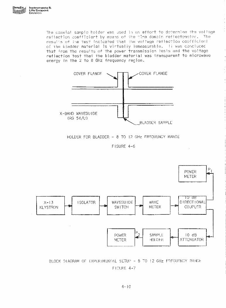
HOLDER FOR BLADDER - 8 TO 12 GHz FREQUENCY RANGE
BLOCK DIAGRAM OF EXPERIMENTAL SETUP - 8 TO 12 GHz FREQUENCY RANGE
EXPERIMENTAL SETUP FOR PRELIMINARY SYSTEM TESTS ON MODE COUNT TECHN I QUE
S I N G L E ANTENNA EXPERIMENTAL SYSTEM
STAT l C LOADl NG - SPS TANK
EXPER I MENTAL SETUP FOR POWER ABSORPT l ON MEASUREMENT ON SPS TANK
VERT ICAL LOADING TEST - SPS TANK
LOADING TEST - C Y L I N D R I C A L TANK, F L A T ENDS, FREQUENCY 2 - 4 GHz, MODULATION I MHz
LOADING TEST - C Y L I N D R I C A L TANK, F L A T ENDS, FREQUENCY 4 - 6 GHz, NO MODULATION
LOAD l NG TEST - C Y L l NDR lCAL TANK, FLAT ENDS, FREQUENCY 2 - 4 GHz, NO MODULATION
4- 16 LOADING TEST - C Y L I N D R I C A L TANK, F L A T ENDS, FREQUENCY 4 - 6 GHz, MODULATION I MHz 4 - 2 0
4 - 17 S T A T I C LOADING - SPS TANK, REFLECTED ENERGY TECHNIQUE 4 - 2 2
4 - 1 8 STAT I C LOAD1 NG - SPS TANK, POWER SAMPL I NG TECHN I QUE 4 - 2 3
4 - 19 EFFECT OF KEL-F ANTENNA GUARD, POWER SAMPLING TECHNIQUE 4 - 2 5
4 - 2 0 S T A T I C LOADING - SPS TANK, POWER SAMPLING TECHNIQUE PROBE ANTENNA OUT OF L I Q U I D 4 - 2 6
4 - 2 1 S T A T I C LOAD1 NG - SPS TANK, POWER SAMPL l NG TECHNIQUE PROBE I N L I Q U I D 4-28

Instrume~s & Life Support Division
L I S T OF FIGURES
PAGE NUMBER F I GURE NUMBER
4 - 2 2 S T A T I C LOADING - SPS TANK, MODE COUNr TECHNIQUE PROBE ANTENNA OUT OF L l Q U l D
S T A T I C LOADING - SPS TANK, MODE COUNT TECHNIQUE PROBE ANTENNA I N L I Q U I D
S T A T I C LOADING - SPS TANK, POWER SAMPLING TECHNIQUE LOOP ANTENNA OUT OF L I Q U I D 4 - 3 2
S T A T I C LOADING - SPS TANK, POWER SAMPLING TECHNIQUE LOOP ANTENNA I N L I Q U I D 4 - 3 4
S T A T I C LOAD1 NG - SPS TANK, POWER SAMPL i NG TECHNIQUE LOOP ANTENNA OUT OF L I Q U I D , BETTER COUPLING 4 - 3 5
S T A T I C LOADING - SPS TANK, POWER SAMPLING TECHNIQUE LOOP ANTENNA OUT OF L I Q U I D , BEST COUPLING 4 - 3 6
S T A T I C LOADING - SPS TANK, POWER SAMPLING TECHNIQUE LOOP ANTENNA I N L l Q U l D 4 - 3 7
VERT ICAL LOADING TEST - SPS TANK, ANTENNA OUT OF L I Q U I D 4 - 3 8
VERT ICAL LOADING TEST - SPS TANK, ANTENNA I N L I Q U I D 4 - 4 0
VERT ICAL LOADING TEST - SPS TANK, NO ANTENNA 4 - 4 I
ANGULAR LOADING TEST - SPS TANK, ANTENNA I N L I Q U I D 4 - 4 2
BLOCK DIAGRAM OF RF GAG l NG SYSTEM 5 -2
M U L T I P L E TANK E X C I T A T I O N 5 - 3
RF OSCILLATOR SWITCHING FOR MULTI-RANGING OF GAGING SYSTEMS 5 - 4
MASS INACCURACY - TECHNIQUE A 5 - 5
TECHNIQUE C 5 - 6
NORMALIZED RESPONSE - POWER SAMPLING TECHNIQUE 5 - 7
MASS INACCURACY, TECHNIQUE C
TECHNIQUE B GAGING SYSTEM
NORMALIZED RESPONSE - ENERGY REFLECTION TECHNIQUE 5- 10
MASS INACCURACY - TECHNIQUE B 5-1 1
BENDIX S O L I D STATE OSCILLATOR 5- 12
TRANSISTOR OSCILLATOR SCHEMATIC DIAGRAM 5 - 14
T Y P I C A L VARIAT IONS I N OUTPUT POWER FOR TWO TAP P O S I T I O N S 5 - i 6
OSCILLATOR TUNING CURVE
B A S I C CIRCULATOR

L I S T OF TABLES
TABLE NUMBER
3- 1
3-2
MEASURED D I E L E C T R I C PROPERTIES OF PROPELLANTS
EXTRAPOLATED ELECTRICAL PROPERTIES OF PROPELLANTS FROM 0 . 5 TO 4 GHz
COMPUTED RESONANT FREQUENCIES OF THREE TEST C A V I T I E S
RESONANT C A V I T Y PARAMETERS
C A V I T Y DIMENSIONS FOR 2 GHz OPERATION
LOADING DEPENDENCY - RECTANGULAR C A V I T Y
RESPONSE OF N204
AEROZINE 5 0 , MMH RESPONSE
AEROZINE 50, MMH RESPONSE
AEROZINE 50 , MMH RESPONSE
STAND l NG WAVE RAT I 0 DATA FOR 3/8" SPACER FOR METHYL ALCOHOL, I N THE 2 - 4 GHz REGION
TRANSMITTED POWER FOR A FREQUENCY RANGE OF 2 TO 4 GHz
ATTENUATION CHARACTERISTICS OF BLADDER SAMPLE
LOADING DEPENDENCE - SPS TANK EXCLUSIVE OF A L L I NTERNAL HARDWARE
RESPONSE FOR A 5 0 % LOADING TANK AT VARIOUS ANGULAR P O S I T I O N S TO VERT ICAL
LOADING DEPENDENCE - SPS TANK INCLUSIVE OF A L L l NTERNAL HARDWARE
S T A T I C LOADING TEST - SPS TANK - TECHNIQUE B
LOADING DEPENDENCE - TECHNIQUE C
S T A T I C LOADING TEST - SPS TANK - TECHNIQUE C
TECHNIQUE A RESPONSE FOR PROBE IN, AND OUT OF L I Q U I D
S T A T I C LOADING TEST - SPS TANK - TECHNIQUE C
STAT l C LOAD1 NG TEST - SPS TANK - RADOME PROBE GUARD
4- 13 S T A T I C LOADING TEST - SPS TANK - LOOP ANTENNA
PAGE NUMBER

Inaruments & Li f e Support Bivisisrr
FOREWORD
T h i s I n t e r i m Report was prepared by t h e Inst ruments and L i f e Support D i v i s i o n o f t h e Bendix Co rpo ra t i on under Con t rac t NAS 9-6751, "To I n v e s t i g a t e and Design a Radio Frequency (RF) Mass Gaging Technique Independent o f G r a v i t y " . The work was admin is te red under t h e d i r e c t i o n o f t h e Na t i ona l Aeronau t i cs and Space A d m l n i s t r a t i o n Manned Spacecra f t Center.
T h i s r e p o r t covers work conducted f rom May 15, 1967 t o November 15, i967.
Prepared by
P r o j e c t Eng i neer
R e E, Resh Manager F l u i d Measurements
A d m i n i s t r a t i v e Engineer
Approved by
D i r e c t o r o f Engineering
P u b l i c a t i o n No, 3914,.1-68-1

lnstrumerrts & L i f e Support Division
ABSTRACT
Th is repo r t documents the work performed i n a p o s f t i v e gaging sysfem f e a s l b i l i t y s-fudy, Three RF techniques o f mass gaging were studled,both theo reP ica l l y and experimental ly, t o determine t h e l r capabl l i t y t o qaqe t h e prope! Iants, N204, Aerozlne 50 and MMH, i n Apal lo or LEM spacecraf t tanks,
The t h e o r e t i c a l work p r e d l c t s t h e response o f each technique re%afPve t o t h e propel l an ts and tanks, The experimental eva luat ion o f t h i s theory was performed using a scale model SPS tank, and a N204 simulant, A sfudy was aZso made sf t h e d t e % e c t r i c p r o p e r t i e s o f t he p rope l l an ts over the expected range o f ope ra t i np candi f fons, F i n a l l y , a preliminary s p e c i f i c a t l o n was made o f t he sysfern9s expected eharac ter isP lcs and components needed f o r t h e f l i g h t lrnplemeniation sf each o f The ?echnlques,

Instruments & l i fe Support Division
SECTION I
I NTROOUCT P ON
The B ~ n d l x C o r ~ o r a t i o n , Instruments R L i f e Supoort D i v i s ion , r e s p e c t i v e l y subm9-t-s Th9s i n t e r i m Report t o t h e Manned Spacecraft Center (MSCI t o document t h ~ nrocrlress made du r ing t h e pe r iod May 15, 1967 t o November 15, 1967, on NASA Contract NAS 9-6751, v'To l nves t i aa te and Design a Radio Frequency (RF? Mass GaqPnq Technique Independent o f Gravi ty f ' , The work performed under t h i s c o n t r a c t i s based on the proposed program p lan submit ied 2s a p o r t i o n o f Bendix Pub! lcatPon No, 3564-66, Revis ion A, "Technical Proposal f o r P c c i t i v e Gaging System f e a s i b l l i t y Studytf, OpPlon A, as mod i f ied by l e t t e r dated February 3, 1969,
The work was d i v ided i n t o two phases w i t h i n the proposed program, Dur ing t h e f i r s t phase, a t h e o r e t i c a l ana lys is was performed d e t a i l ing t h e measuremenf o f f ue l d i e l e c t r i c p roper t ies , and t h e performance o f several RF Measurement Systems - s % a t ! v e t o a stworst" Apo i lo o r LEN Spacecraft f ue l and tank conf ipuraf- ion, Experimental work was then conducted on a l i m i t e d bas is t o verPfy f h e theore$;cal predlcPions o r t o eva lua te measurement techniques, The experiments t o dsferm9ne system performance were performed us ing sca le model SPS tanks, propel Eent sSrnu3~~~f -s and l aboratory type t e s t hardware,
This r e p o r t i nd i ca tes t h a t p r e d i c t i o n s o f f u l 1-scale system performance can be made by seal i n g t h e r e s u l t s obtained from t h e ode! tank and s imulated f u e l study t o t h e ac tua l tank, The performance o f t h e system wDth o the r f u e l s i n t he p a r t l e u l a r tank c o n f i g u r a t i o n i s included t o nnabie a cholce o f a bes t gagina teehnlque f o r a p a r t i c u l a r tank and fue i combination,
During the second phase, an ana lys is was made o f p o t e n t i a l f a ! l u re areas and t h e l r e f f e c t on t h e system performance, Th is ana iys i s was o f a l i m i t e d scope because of t he 7heoretOcal na ture o f t h i s study, As such, it i s concerned w i t h o n l y t h o major sources o f fa1 l u r e pred ic ted f o r a system component sf a pa r t l cuPar c l a s s or prPnePpIe o f operat ion,
Csnekusions on t h e performance o f a proposed RF gaging system based on the con- cepts OwvesPlgated, and recommendations f o r design, developmen? and f u t u r e evaiua-kion, are made i n t h i s repo r t based on the r e s u i t s o f the anaEysPs and experiments conducted du r ing the i nves t i ga t i on ,

Bendix instruments (l wm #A* Life Suppert ** Division
SECTION E i
PROGRAM OBJ ECT l VES
Performance requi rements and des ign o b j e c t i v e s f o r t h e p r o p e l l a n t mass gaging system s tud ied d u r i n g t h i s program were based on t h e des ign g o a l s l i s t e d below:
a ) The system w i l l have a mass gag i ng accuracy o f f 0.5% o f f u l l sca le , v a r y i n g l i n e a r l y t o 0.25% o f f u l l s ca le a t t h e 10% f u l l c o n d i t i o n m a i n t a i n i n g 0.25% o f f u l l s ca le down t o zero. The system's maximum response t i m e ( f o r a s i n g l e measurement) w i l l be 0.2 second and t h e system w i l l have a r e s o l u t i o n o f * 0.1% o f f u l l sca le . T h i s accuracy w i l l be ma in ta ined under Zero "GI' as we l l as normal g r a v i t y c o n d i t i o n s , and under a l l f i l l i n g and o p e r a t i n g c o n d i t i o n s .
b ) The system w i l l be compat ib le w i t h A p o l l o o r LEM propel l an t s , wh i c h a r e N204-ox i d i zer , 50% UDMH/50% Hydraz i ne and MMH f u e l s.
c ) The system w i l l be designed t o be capable o f easy t a n k i n s t a l l a t i o n , r e q u i r i n g a minimum o f m o d i f i c a t i o n i n e x i s t i n g A p o l l o o r LEM t a n k hardware.
d ) The system accuracy w i l l be ma in ta ined independent o f t a n k p ressure and f l u i d temperatures o f 0 t o 300 p s i a and +40 t o + 9 0 ' ~ r espec t i ve 1 y .
e l To make t h e system compat ib le w i t h man-rated a p p l i c a t i o n s , t h e system w i l l have a des ign goal o f meet ing t h e f o l l o w i n g v i b r a t i o n and a c c e l e r a t i o n requi rements :
V i b r a t i o n Acce l e r a t i on
0 - 1 4 c p s @ I g 14 - 40 cps @ 10 g ' s 40 - 100 cps @ 20 g ' s
100 - 2500 cps @ 40 g ' s
0 - 12 g ' s i n any d i r e c t i o n
Only an a n a l y s i s showing c o m p a t a b i l i t y w i l l be performed t o show t h a t t hese goa l s can be met. Tes t i ng o f t h e p ro to t ypes w i l l n o t be performed f o r t h i s purpose.
f ) The system w i l l have a maximum weight o f f i f t y ( 50 ) pounds, exc l ud ing i n t e r c o n n e c t i n g cab les . Every e f f o r t w i l l be made t o reduce t h e system weight below f i f t y ( 50 ) pounds.
g:) The system power requi rements w i l l be 28 v o l t s DC, I ampere con t inuous and w i l I be l i m i t e d t o 5-second,5-amp surges.

IoslrumeRes & Life Support Division
h ) The system o u t p u i w i l l be p a r a l l e l and s e r i a l b i n a r y s i g n a l s .
i ) The sysi-em w i l l be adapi-able t o a v a r i e f y o f c y l i n d r i c a l and/or sphe r i ca l t anks o r o t h e r t a n k geometr ies as s p e c i f i e d by t h e c o n t r a c t i n g agency. Where t h e proposed gaging techn ique does n o t s a t i s f y t hese s p e c i f i e d requi rements , t h e e f f e c t s o f t h e d e f i c i e n c i e s w i l l be d e t a i l e d .
j) The system w i l l i n c l u d e t h e c a p a b i l i t y o f p r o v i d i n g mass gag ing f o r up t o f o u r separate tanks.
A d d i t i o n a l program o b j e c t i v e s a r e covered i n t h e proposal re fe renced i n Sec t i on I .

Berndixp Instruments & &@ Life Support
:s!g&@ Division
SECTION I l l
THEORETICAL STUDIES
3. 1 l NTRODUCT l ON
The o p e r a t i o n a l t h e o r y o f techn iques used t o measure p r o p e l l a n t mass c o n t e n t i n spacec ra f t t a n k s i s covered i n t h i s sec t i on . A l s o inc luded i s a d i s c u s s i o n o f a n a l y t i c a l techn iques used t o determine t h e e l e c t r i c a l p r o p e r t i e s o f space- c r a f t p r o p e l l a n t s . The mass gaging techn iques t h a t a r e i n v e s t i g a t e d have as a common c h a r a c t e r i s t i c , e x c i t a t i o n (by i l l u m i n a t i o n ) o f t h e f u e l o r o x i d i z e r t anks w i t h energy i n t h e RF r e g i o n o f t h e e lec t ro -magnet i c spectrum. Each techn ique i n v e s t i g a t e d , has been shown t o have advantages and d isadvantages f o r a p a r t i c u l a r f u e l o r o x i d i z e r because t h e c h a r a c t e r i s t i c response o f each proposed gaging system depends i n a d i f f e r e n t way on t h e d i e l e c t r i c and l o s s t angen t p r o p e r t i e s . Thus f o r a p a r t i c u l a r p r o p e l l a n t , where one t echn ique f o r mass measurement may show a poor s e n s i t i v i t y , ano ther may have a good s e n s i t i v i t y . An unders tand ing o f t hese d i f f e r e n c e s can be used t o i s o l a t e techn iques which g i v e t h e b e s t s e n s i t i v i t y f o r each f u e l o r o x i d i z e r .
A l so o u t l i n e d i n t h i s s e c t i o n a r e t h e p r o p e l l a n t s and t a n k c o n f i g u r a t i o n s con- s i d e r e d i n t h i s s tudy . The r e s u l t s o f exper iments t h a t were performed t o supplement t h e t h e o r e t i c a l a n a l y s i s and eva lua te proposed gaging techn iques a r e presented i n Sec t i on IV.
3.2 PROPELLANT TANKS AND FUELS STUDIED
The p r o p e l l a n t t anks s t u d i e d were those used on t h e A p o l l o o r LEM spacec ra f t . A p a r t i c u l a r t a n k c o n f i g u r a t i o n , t h a t o f t h e SPS tanks, was chosen as a "wors t " type, c o n t a i n i n g t h e elements shown i n F i gu re 3-1. The t ank c o n f i g u r a t i o n was termed wors t because o f t h e presence o f p ipes, screens and t h e sump reg ion , which e l e c t r i c a l l y i s o l a t e d reg ions o f t h e t a n k . Another s t r u c t u r e i nc l uded as a p o s s i b l e t a n k element, was a b ladder used f o r p o s i t i v e p r o p e l l a n t expu l s i on . A r e p r e s e n t a t i v e p o r t i o n o f b ladder m a t e r i a l was ob ta ined f rom t h e c o n t r a c t i n g agency f o r e v a l u a t i o n o f i t s e f f e c t on t h e system performance.
The f l u i d s t o be used i n t h e t anks were N204-ox id izer , 50% UDMH/~O% Hydraz ine and MMH f u e l s . Because o f t h e hand l i ng problems assoc ia ted w i t h t hese f l u i d s , t h e phys i ca l and e l e c t r i c a l p r o p e r t i e s o f these f l u i d s were s imu la ted us i ng m i x t u r e s o f hydrocarbon f l u i d s . The s imu lan t f l u i d s were se lec ted t o have e l e c t r i c a l p r o p e r t i e s s i m i l a r t o t h e a c t u a l f u e l s and o x i d i z e r .
0 A t ank o p e r a t i n g r e g i o n from 0 t o 300 p s i a and +40° t o +90 F, was g i "en by MSC as r e p r e s e n t a t i v e o f t h e thermod namic environment o f t h e o x i d & z e r and f u e l s .
0 A p ressure range o f I ATM t o I O-Y t o r r and temperatures o f +40 t o 190 F, was t aken as t h e environment i n t h e equipment bay reg ion .


Instruments & Life Support Divisiom
V i b r a t i o n and a c c e l e r a t i o n were g i ven as f o i lows:
V i b r a t i o n
0 - 1 4 c p s @ I g 14 - 40 cps @ 10 g ' s 40 - 100 cps @ 20 g ' s
100 - 2500 cps @ 40 g ' s
Acce i e r a t , U
0 - 12 g i s i n any d i r e c t i o n
The f l u i d mass i n f l u x o r o u t f l u x c o n d i t i o n s i n t h e t a n k were g i ven as those p resen t f o r a l l f i l l i n g and o p e r a t i n g c o n d i t i o n s . These were taken a s a maximum o f 0.5% o f f u l l t a n k mass change i n 0.2 second t o agree w i t h t h e accuracy and t i m e response goal s.
3.3 PROPELLANT PROPERTIES STUDY
Because t h e s e n s i t i v i t y o f t h e mass gaging techn iques depends on t h e d i e l e c t r i c cons tan t and l oss t angen t o f t h e p r o p e l l a n t s , a knowledge o f these p r o p e l l a n t p r o p e r t i e s ove r t h e f requency and env l ronmenta i range o f i n t e r e s t was v i t a l t o t h i s s tudy . T h i s s e c t i o n d e t a i l s t h e thorough e f f o r t t h a t was made t o e i t h e r l o c a t e a v a i l a b l e i n f o r m a t i o n o r t o measure these d i e l e c t r i c p r o p e r t i e s .
3 0 3 , i L i t e r a t u r e Search
A search was made o f a l l a v a i l a b l e t e c h n i c a l i n f o r m a t i o n concern ing t h e p r o p e r t i e s o f N i t r o g e n Te t rox i de , Aeroz ine 50 and Monomethyl Hydraz ine, The main sources o f l p h y s i c a l and chemical p r o p e r t i ~ s were t h e r e p o r t s by t h e A e r o j e t Co rpo ra t i on and t h e Bel l Aerospace Repor t b u t t hese d i d n o t c o n t a i n i n f o rma t i on concern ing t h e e l e c t r i c a l p r o p e r t i e s . I n t h i s f i e l d , t h e o n l y 3 pub l i shed work o f va l ue was authored by G. A. Burns and C , J , Meierbach to l , who measured t h e e l e c t r i c a l p r o p e r t i e s o f these f l u i d s , a t f r equenc ies o f approx imate ly 100 MHz and 600 MHz. An e x t r a c t f rom t h e i r r e p o r t i s shown i n Table 3-1. H e l i x Research, Inc. (Burns and Me ie rbach to l ) were employed as c o n s u l t a n t s by Bendix, Ins t ruments & L i f e Support D i v i s i o n t o t h e o r e t i c a l l y i n v e s t i g a t e t h e e q u i v a l e n t e l e c t r i c a l p r o p e r t i e s o f t h e f l u i d s a t f r equenc ies i n t h e range o f 500 MHz t o 4 GHz. An e x t r a c t o f t h i s i n f o r m a t i o n i s shown i n Tab le 3-2, These r e s u l t s a r e f o r l i q u i d s under a tmospher ic p ressure . There i s a v a r i a t i o n o f d i e l e c t r i c cons tan t and l oss t angen t w i t h p ressu re as we l l a s temperature, and t h e r e s u l t s should be p l o t t e d as a v a r i a t i o n o f p o l a r i z a b i l i t y ,
3 , 3 , 2 E l e c t r i c a l P r o p e r t i e s as a Func t ion o f Frequency and Temperature
I n t h e d i scuss ion t h a t f o l l ~ w s , equa t ions a r e presented w i t h o u t p roo f i n t h e i n t e r e s t o f b r e v i t y . Debye de r i ved t h e f o l l o w i n g equa t ions based on t h e assumption t h a t d i p o l e e q u i l i b r ium, when an ex te rna l f i e l d i s removed, i s a t t a i n e d e x p o m t i a l ~ y w i t h t ime ,

Inszmmerpts & Life Support Division
where: E ' and E" = respec t i ve l y t h e rea l and imaginary pa r t s o f complex r e l a t i v e d i e l e c t r i c constant ( i .e., E* = E ' - i ~ " )
E = t h e s t a t i c d i e l e c t r i c constant 0
E- = t h e value which i s asympto t ica l ly approached by E ' a t wavelengths s u f f i c i e n t l y shor ter than Am t o make E"
r e l a t i v e l y small
Am = t h e wavelength corresponding t o t h e lowest resonance a b s ~ r p t i o n frequency i n t h e mater ia l in quest ion
A 0 = the wavelength o f t h e i nc iden t rad ia t i on .
TABLE 3- 1
MATER l AL
Aerozine 50
MMH
MEASURED DIELECTRIC PROPERTI
FREQUENCY TEMPERATURE I OF
OF PROPELLANTS
D l ELECTR l C LOSS CONSTANT TANGENT

Instruments & Life Support Division
TABLE 3-2
EXTRAPOLATED ELECTRICAL PROPERTIES OF PROPELLANTS FROM 0,5 TO 4 GHz
MATER i AL
Aeroz ine 50
MMH
FREQUENCY I EMPgRATURE D l ELECTRiC F CONSTANT
40 24.36
90 20.36
40 23.96
9 0 20.30
40 23. '72
9 0 20.26
4 0 21 .oo 9 0 17.48
40 21.24
9 0 17.78
LOSS TANGENT
--
The va lues f o r co and cm may be expressed by Debye form of t h e C iaus i t i s - Mosso t t i equa t ion :

Ins4ramenls & L i f e Support Division
- U
c .- o r
-u *- 5 2 R I L L L O B ) + m + s n 8 -- lu *-
O N W e
W 8
FIGURE 3-2

Instruments & Life Support Division
2 where: a = t h e p o l a r i z a b i l i t y due t o bond d i s t o r t ~ o n and -
0 " I s
p o l a r i z a b i l i t y due t o d i p o l e o r i e n t a t r o n 3 kT
p = t h e permanent d i p o l e moment N = Avagadro's number k = Bol tzman's cons tan t T = t h e temperature i n degrees K e l v i n M = mo lecu la r weight p = d e n s i t y
Two cases may be cons idered :
a ) Non-Polar M a t e r i a l s ( M a t e r i a l s whose molecu les do n o t c o n t a i n permanent d i p o l e s ) . I n t h i s case 11 = 0 and Equat ions 3.3 and 3.4 r e s u l t i n & z Here t h e lowest resonance a b s o r p t i o n f requency f a l l s i n t h e i 8 f r a red r e g ion and i s due t o mo lecu la r bond osc i I l a t i ons as shown i n F i gu re 3-2.
When such i s t h 2 case, cm may be s e t equal t o t h e square o f t h e index o f r e f r a c t i o n n , i n Equat ions 3.1 and 3.2, I t may be seen f rom Equat ions 3.1 and 3.2 t h a t t h e v a r i a t i o n o f E ' and E" due t o changes i n temperature and p ressure a r e due o n l y t o t h e f a c t t h a t p i s a f u n c t i o n o f T and p . C o e f f i c i e n t s o f thermal expansion and c o m p r e s s i b i l i t y may be found i n t h e l i t e r a t u r e .
b l P o l a r M a t e r i a l s ( M a t e r i a l s whose molecu les c o n t a i n permanent d i p o l e s ) I n t h i s case t h e lowest abso rp t i on f requency f a l l s i n t h e microwave r e g i o n and i s due t o d i p o l e o r i e n t a t i o n i n t h e ex te rna l f i e l d as shown I n F i gu re 3-3. Under t h i s c o n d i t i o n Equat ions 3.3 and 3.4 h o l d a s t h e y a r e w r i t t e n . A problem a r i s e s i n e v a l u a t i n g cm, however, s i n c e g e n e r a l l y a i s no t known. The bes t s o l u t i o n i s t o d i r e c t l y measure it a t 0
f requenc ies s u f f i c i e n t l y h i gh t o i nsu re t h a t t h e c o n d i t i o n i n t h e d e f i n i t i o n o f f o l l o w i n g Equat ion 3.2 i s met, Other methods m igh t be t o measure E i n t h e s o l i d s t a t e where t h e permanent d i p o l e s a r e
0 e f f e c t i v e l y " f r ozen in", and do no t c o n t r i b u t e t o t h e p o l a r i z a t i o n o r , measure c a t s u f f i c i e n t l y h i g h temperatures t o i nsu re c a n c e l l a t i o n o f d i p o l e o r y e n t a t i on i n t h e e x t e r n a l f i e l d by t h e tendency toward random o r i e n t a t i o n due t o thermal mot ion.
I t may be seen f rom Equat ion 3.3 t h a t when a permanent d i p o l e e x i s t s , t h e p o r t i o n o f t h e p o l a r i z a t i o n due t o d i p o l e o r i e n t a t i o n i s an inverse
2 f u n c t i o n o f t h e temperature, So l v i ng Equat ion 3.3 f o r Am , we have:
Even when c0 and E a r e known e i t h e r from Equat ions 3.3 and 3.4, o r from exper iment, E? i s s t i l l some unknown f u n c t i o n o f temperature. Therefore, even i f E ' were known f o r t h e e n t i r e r a d i o f requency spectrdm a t a g i v e n temperature, t h e va lue o f X a t some new tempera tu re cannot m be p r e d i c t e d w i t h o u t a t l e a s t one measurement o f E ! a t t h e new temperature,

Bendix Instruments 8t Life Support I >it!i?ic,~&
a, 5 L a, > - - 0 U a t C 3 aa, co 0 L - s L 0 0 0 u m a m
e- a .- a, E m u L

InstrumeWs & Life Fewport Division
I t i s d e s i r a b l e t o be a b l e t o approximate t h e d i e l e c t r i c cons fan t and l oss tangen t o f c e r t a i n propel l a n t s by room-temperature m i x t u r e s t h a t e l im ina te - hand l i ng problems. ihey may be done by m i x i n g a p o l a r I i q u i d ( h i g h d i e l e c ? r i c c o n s t a n t ) w i t h a nonpo la r l i q u i d ( r e l a t i v e l y low d i e l e c t r i c c o n s t a n t ) . By chdos i ng p roper p r o p o r t i ons i n t h e m i x tu re , temperature and frequency, a I most any d e s i r e d combina t ion o f d i e l e c t r i c cons tan t , E ' and l oss tangen t may be ob ta ined , p rov i ded t h e y f a i l somewhere between t h e va lues o f t h e c o n s t i t u e n t l i qu ids .
Equat ions 3.3 and 3.4 may be r e w r i t t e n f o r such m i x t u r e s as :
where C , and C2 a r e t h e mole f r a c t i o n s (moles per u n i t volume) o f t h e p o l a r and nonpolar I ~ q u i d s respectively.
I t may be shown t h a t Equat ions 3.1 and 3.2 may be m o d i f i e d f o r such a case as :
where C i s t h e c o n c e n t r a t i o n o f t h e p o l a r s o l u t e i n moles per u n i t volume.

Instruments & L i f e Support Division
i t must be noted t h a t t h e above equa t ions were de r i ved w i t h o u t regard t o so- c a l l e d "Solvent E f f ec t i i , T h i s e f f e c t accounts f o r t h e measbred d i f f e r e n c e s i n t h e va lues f o r d i p o l e moments i n gases and i n s o l u t i o n . The d i f f e r e n c e i s caused by t h e i n t e r a c t i o n o f t h e f i e l d s o f permanent d i p o l e s and by t h e i n d u c t i o n o f d i p o l e s i n nonpo la r molecu les due t o f i e l d s o f nearby permanent d i p o l e s .
, ! n Equat ions 3.3, 3.4, 3.6 and 3.7 va lues f o r a and u should be regarded as average mic roscop ic va l ues a t t h e temperature and c o n c e n t r a t i o n i n q t ies t ion . Thus, t h e p rev i ous assumption t h a t these va lues a r e cons tan t i s t r u e o n l y f o r a g i v e n m ix tu re . Because o f s o l v e n t e f f e c t , Equat ions 3.8 and 3.9 a r e accu ra te o n l y f o r d i l u t e s o l u t i o n s o f p o l a r s o l u t e s i n nonpolar so l ven t s , i n more con- c e n t r a t e d s o l u t i o n s , t h e equa t ions can o n l y p r o v i d e approx imate p o r p o r t i o n s t o begin exper imenta l m i x i ng t o ach ieve s p e c i f i c va lues .
I t can be shown t h a t f r g m Equat ions 3.8 and 3.9, a p l o t o f E" a g a i n s t E ' g i v e s a s e m i c i r c l e w i t h c0 and as o p p o s i t e ends o f a d iameter on t h e E ' a x i s , when t h e temperature and p ressure a r e he ld cons tan t . S ince a c i r c l e i s d e f i n e d by t h r e e po in t s , t h r e e measurements o f E ' and E" a t r e l a t i v e l y wide frequency spac ing should be enough t o d e f i n e t h e whole v a r i a t i o n o f E ' and E" w i t h f requency. Exper imenta l l y , d i f f i c u l t y i s found u s u a l l y because t h e measure- ment techn iques may have t o be d i f f e r e n t f o r each o f these f requenc ies .
3.3.4 Methods o f Measurement o f D i e l e c t r i c Constant and Loss Tangent
The wide v a r i a t i o n o f t h e e l e c t r i c a l parameters o f m a t e r i a l s used i n microwave work, t o g e t h e r w i t h t h e wide frequency range o f t h e microwave spectrum, means t h a t t h e r e can be no one method o f measurement o f t hese parameters. Usua l l y , methods a r e chosen f rom a knowledge o f t h e f requency a t which t h e parameters a r e wanted, and es t imated va lues o f t h e parameters. I f t h e parameters ar-e t h e n d i f f e r e n t f rom t h e es t imate , t h e measurement w i l l n o t work, b u t a c l o s e r guess can t hen be made t o t h e va lues o f t h e parameters, and a b e t t e r method chosen,
The i n i t i a l method o f measurement decided upon was a t ransmiss ion- type resonant c a v i t y technique, whereby t h e resonant f requency and t h e Q OF a g i ven mode a r e measured when t h e c a v i t y i s empty and when i t i s f i l l e d w i t h t h e f l u i d . T h i s method i s s u i t a b l e f o r low d i e l e c t r i c cons tan t m a t e r i a l , and f o r low l oss m a t e r i a l s , For h i g h d i e l e c t r i c constants , ve r y l i t t l e power e n t e r s t h e m a t e r i a l because o f t h e l a rge impedance mismatch a t t h e i n p u t probe, and f o r h i g h l oss tangen ts t h e m a t e r i a l absorbs a lmost a l l o f t h e power which e n t e r s it. Thus, i n t hese cases, t h e resonance cannot be seen c l e a r l y enough w i t h o u t spec ia l apparatus. As w i l l be seen from Paragraph 4 ,2 , l , Sec t i on i V , when t h i s method was t r i e d with N204 and MMH, no app rec i ab le power t r ansm iss i on cou ld be ob ta ined w i t h t h e c a v i t i e s used, and t h i s i n d i c a t e d e i t h e r a h i g h d i e l e c t r i c ~ c o n s t a n l - o r a h i g h l oss f a n g e n t f o r t h e p r o p e l l a n t s .
A v a r i a t i o n on t h i s method i s t h e use, n o t o f t h e l i q u i d s themselves, b ~ t o f m i x t u r e s o f t h e f l u i d w i t h r e l a t i v e l y l oss l ess l i q u i d s . From t h e known voiume r a t i o , t h e va lue f o r an u n d i l u t e d so lu" ron can be found by ex . t r apo la t i on . T h i s method was t r i e d i n t h e l a b o r a t o r i e s w i t h Methyl A lcohol d i l u t e d w i t h Benzene, As can be seen f rom Paragraph 4.2,2, Sec t ion I V , t h e a l coho l was so lossy t h a t o n l y concen t ra t i ons o f a few percen t o f a l coho l cou ld be measiired, T h k would mean t h a t e x t r a p o l a t i o n t o 100% would be very inaccura te , Because o f t h i s ,

Instrurnenls & L i f e Support Division
i t was decided t o abandon t h i s method, Next, t h e Roberts-Von H i p p e l method was -tried, T n i s has been used s u c c e s s f u l l y i n t h e l abo ra to r y t o measure Methyl Alcoho l , which i n d i c a t e s t h a t i t cou ld probably be used t o measure Aerozine-50 and MMH, success fu l l y . Another method has been s tud ied which uses small samples o f t h e f l u i d t o p e r t u r b t h e resonant f requency and Q o f a c a v i t y . T h i s i s a use fu l method f o r measuring f l u i d s w i t h l a rge d i e l e c t r i c cons tan t and loss tangents ,
The resonant c a v i t y method i s one o f t h e most standard methods o f measuring t h e d i e l e c t r i c p r o p e r t i e s o f f l u i d s w i t h reasonable e l e c t r i c a l c h a r a c t e r i s t i c s . Usua l l y , a c y l i n d r i c a l c a v i t y i s made from low l o s s m a t e r i a l , and a p a r t i c u l a r mode, o r s e t o f modes i s chosen f o r study, One o r two probes a r e p laced i n s u i t a b l e p o s i t i o n s i n t h e c a v i t y , and w i t h a swept s i gna l genera to r and an osc i l l oscope , t he modes a r e examined, The apparatus may be s e t up as e i t h e r F igu re 3-4 o r 3-5. The method i s q u i t e standard, and may be found I n most t e x t b o ~ k s , ~ f o r examp l e, "Techn iques Of M icrowave Measurement" by C. G. Montgomery , bu t a s h o r t o u t l i n e now fo l l ows . A resonant c a v i t y i s made so t h a t a p a r t i c u l a r mode has a resonant f requency g i ven by:
where Fo i s t h e frequency around which t he parameters a r e t o be measured, and E i s a rough guess o f t h e d i e l e c t r i c constant . Two ho les a r e d r i l l e d i n t h e c a v i t y t o t a k e small probes. The ho le p o s i t i o n s and probe t ypes a r e chosen f o r s u i t a b l e coup l i ng t o t h e mode. Then, w i t h apparatus such as t h a t shown i n F i g u r e 3-4 o r 3-5, t h e mode i s examined. The probes a r e e i t h e r reduced i n s ize , o r , i n t h e case o f loop antennas, ro ta ted , u n t i l t h e w i d t h o f t h e resonance a t t h e h a l f power po in ts ,does no+ decrease f u r t h e r . The resonant f requency F i and t h e Q o f t h e resonance a r e then measured. The c a v i t y i s then f i l led w r t h t h e f l u i d , and t h e exper iment repeated, g i v i n g a resonant f requency F2 and a Q, Q2. Then t h e d i e l e c t r i c cons tan t E o f t h e l i q u i d i s g i v e n by:
The Q's a r e g i ven by:

FREQUENCY MEASUR l NG
DEV l CE
D I E L E C T R I C MEASUREMENT USING RESONANT C A V I T Y AND TRANSMITTED POWER TECHNIQUE

Ins(ru
rnerp
ts &
L
ife Su
pp
ort
Div
ision
FIGU
RE
3-5
3-13

Instrumemts 8t Life Support Division
where : QW(F, )
= t h e Q o f t h e w a l l s o f t h e c a v i t y a t frequency F I
I
O W ( F = t h e Q o f t h e wa I I s o f t he c a v i t y a t f requency F 2 2
'd (F2 ) = t h e Q o f t h e d i e l e c t r i c a t f requency F2
Now :
where a = t h e e l e c t r i c a l c o n d u c t i v i t y o f t h e metal w a l l s
Then:
Thus:
and :
There fo re :
There fo re :
Qd o f t h e d i e l e c t r i c i s r e l a t e d t o t h e loss tangent by:
There fo re :
- Qd ' E t a n 6
- 1 -1 /4 - 1 Q, = E Q 1 + t a n 6
Thus:
Thus, Equat ions 3,10 and 3.11 g i v e t he d i e l e c t r i c cons tan t and t h e loss Sangen? of i-he d i e l e c t r i c m a t e r i a l .

lnstrurnertls & Life Support Division
For g r e a t e r accuracy, t h e Q o t t h e probe, o r probes, may be tdken i n t o account by us i ng s l o t t e d I ~ n e t e c h n ~ q u e s . The s l o t t e d i ~ n e i s ~ n s e r t e d be fo re t h e i n p u t probe, and t h e impedance o f t h e probe i s measured versus f requency as t h e resonance i s passed through. T h i s impedance i s p l o t t e d on a Smith Char t , and from t h i s , t h e Q o f t h e probe may be separated from t h e Q o f t h e c a v i t y . For t h e two probe method, t h e second probe i s te rm ina ted i n a matched load w h i l e t h e measurement i s made, and t h e n t h e process i s repeated w i t h t h e o t h e r probe a s an i n p u t probe, w h i l e t h e f i r s t i s te rm ina ted i n a matched load, By t h i s method, t h e Q o f t h e probe o r probes, may be found. These Q ' s a r e measured, bo th when t h e c a v i t y i s f u l l , and when it i s empty, and t h e y a r e sub t rac ted from t h e measured Q ' s , Q2 and Q , , t o g i v e more accu ra te va lues o f Q2 and Q I Three smal l c y l i n d r i c a l c a v i t i e s were made, o f d i f f e r e n t dimensions, t o cover t h e f requency range f rom 2 t o 8 GHz. A computer program was r u n t o f i n d t h e resonan t f requenc ies o f a l l o f t h e lower o r d e r modes o f t h e c a v i t i e s . I t was in tended t o cons ide r t h e e f f e c t o f t h e f l u i d s on a se l ec ted few o f t hese modes" The modes and t h e i r r e s p e c t i v e f requenc ies a r e g i v e n on Tab le 3-3.
For lossy l i q u i d s , measurements may be made by m i x i n g t h e I i q u i d s w i t h a l ess lossy l i q u ; d , and measuring t h e f i n a l r e s u l t . By r e p e a t i n g t h e measurements w i t h v a r i o u s concen t ra t i ons , t h e ac tua l va l ue o f t h e parameters may be ob ta i ned by e x t r a p o l a t i o n .
A second method t h a t o f Von H ippe l i s p robab ly t h e most v e r s a t i l e rn t h o d o f 9 d i e l e c t r i c measurement, Based on a paper by Rober ts and Von H ippe l , t h e method u t i l i z e d t h e measurement o f impedance a t t h e su r f ace o f t h e l i q u i d when p laced a t t h e end o f a s h o r t - c i r c u i t e d waveguide. The apparatus i s shown i n F i g u r e 3-6. By measur ing t h e v o l t a g e s tand ing wave r a t i o (VSNR), and p o s i t i o n ot t h e minimum o f t h e s tand ing wave pa t t e rn , t h e su r f ace impedance may be c a l c u l a t e d , From t h i s , and t h e known t h i c k n e s s o f l i q u i d , t h e d ; e l e c t r i c cons tan t and l o s s tangen t o f t h e l i q u i d may be c a l c u l a t e d as f o l l o w s :
Suppose t h e l i q u i d t h i c k n e s s i s d cm, and t h e c h a r a c t e r i s t i c impedance o f t h e waveguide i s Z , Then t h e impedance a t t h e su r f ace o f t h e l i q u i d i s g i ven by:
0
Z = Z t anh 6 d S 0
where: Z ' = t h e c h a r a c t e r i s t i c impedance o f t h e waveguide f i l l e d 0 w i t h I i q u i d
6 = t h e p ropaga t ion cons tan t i n t h e l i q u i d
Now by d e f i n i t i o n :

Instruments & bite Support Division
TABLE 5-13
COMPUTED RESONANT FREQUENCIES OF THREE TEST CAVlT iES
CAV 1 TY I MODE TYPE
5.906" h igh by 2.954" diameter
RESONANT FREQUENCY (GHz) EMPTY

I COAX TO
WAVEGU l DE TRP,?! S I T I ON
APPARATUS FOR ROBERTS-VON HIPPEL VETHOD

Instruments & Life Support Division
where: w = t h e r a d i a n f requency 6 = t h e p ropaga t ion constan+ i n a i r
O = J B f o r no loss, where Bo i s t h e phase change pe r cm i n a i r 0
= t h e permeabi l i t y o f f r e e space,
A lso :
f o r non-magnetic l i q u i d s ,
There fo re :
There fo re :
Z = Z ' t a n h 6 d S 0
- j B o - zo 6 t a n h 6 d
T h i s i s t h e impedance a t t h e su r f ace o f t h e l i q u i d , The impedance a t t h e minimum p o s i t i o n i s g i v e n by:
- 1 - I S-I = (ZsZO + j t a n BO Xo) ( I + jZSZO t a n Bo Xo)'l
Where S i s t h e VSWR, and Xo i s t h e d i s t ance f rom l i q u i d su r f ace t o t h e minimum p o s i t i o n .
T h i s l a s t equa t ion may be w r i t t e n :
- I - I zSzo = ( 5 - j t a n BOXo) ( I - j 5-I t a n Bo X o ) - '
- I S u b s t i t u t i n g f o r ZSZo g i v e s :
j ~ ~ 6 - l t a n h 6 d = ( s - I - j t a n Bo Xo) ( I - j 5- ' t a n Bo Xo)
o r : (6dImi t anh 6 d = ( j B o d ) - l (s- I - j t a n Bo Xo) ( I - j S- I t a n 8, Xo)
- I o r p u t t i n g Bo = 2nXg where X = gu ide wavelength. g
( 6 d j - I tanh 6 d = - j h (2nd) - I ( s - I - j t a n 2n X A 'I ) . , g o g
( I - j ~ - i t a n 2nX h - I ) (3 .12) o g

fnstrumenls & Life Support Division
Given t h e minimum p o s i t i o n X and VSWR(S) means t h a t t h e r igh t -hand s i d e o f t h e equa t ion can be computed. I? ' is a complex number, and s o l u t i o n 8 t o t h e r e s u l t i n g complex equa t lon may be found from graphs i n Von Hippel's book, Thus, Sd i s known, and s i nce d i s known, so i s 6 , T h i s i s reso lved i n t o i t s r e a l and imaginary pa r t s , a and f3. Then t h e d i e l e c t r i c cons tan t and l oss tangen t a r e found from t h e wave gu ide equa t ions .
where: A i s t h e c u t o f f wavelength o f t h e wave gu ide. C
These a r e t h e general equa t ions t o f i n d t h e d i e l e c t r i c cons tan t , and l oss tangen t . For r e l a t i v e l y low l oss m a t e r i a l , Equat ion 3.12 can be s i m p l i f i e d by assuming S tends t o i n f i n i t y , !.en, I /S i s ve r y sma l l . Then:
t a n h 6d A I 2nX0 I 2nX0 = -j -A ( - - j t a n - S A
1 (I + j t a n - 6 d
A 2nd 9 9
A I 2nXo I 2nxO - - -j -A ( - -
2nd S j t a n - + - t a n - A S A
9 9
2 where terms o f t h e o r d e r o f ( I / S ) and above have been ignored.
Expanding t a n h 6d i n t o r e a l and imaginary p a r t s g i v e s :
t anh 6d - t a n ad + j t a n Bd - I
6 d I + j t a n h a d t a n Bd ' d ( a + j B )
Tak ing 6 smal l g i v e s :
6d = (ad + j t a n $d l ( I - j ad t a n Bdl ( a - , i B 6d
f32 d
S u b s t i t u t i n g i n t h e p rev i ous equa t ion g i v e s :

Instruments & Life Support Division
LIQUID SAMPLES
FIGURE 3-7

lnslrumerrls & LiZe Support Division
E q m i iny rea l p a r t s g i v e s :
Equat ing imaginary p a r t s g i ves :
2 h a 2 2rrXo ( t a n Bd - Bd sec Bd) = -9 I
2nd S A (3.161
B2d 9
Equat ions 3.15 and 3.16 g i v e a and B, w i t hou t t h e use o f t ab les , f o r Lse w i t h Equat ions 3.13 and 3.14.
A t h i r d techn ique o f measuring d i e l e c t r i c p r o p e r t i e s o f f l u i d s I s t h e resonant - c a v i t y p e r t u r b a t i o n method. I t has been we l l e s t a b l i s h e d by a number o f au tho rs t h a t t h e resonant f requency o f a c a v i t y mode depends i n a s imple way upon t h e r e a l p a r t o f t h e complex dielectric cons tan t o f t h e m a t e r i a l w i t h i n t h e c a v i t y and t h e Q o f t h e resonant c a v i t y i s s imp ly r e l a t e d t o t he imaginary p a r t o f t h e complex d i e l e c t r i c constant , Genera l l y , the mode se lec ted f o r performing these measurements i s the dominant mode Yn t h e p a r t i c u l a r s t r u c t u r e . On t h i s case, t h e t a s k i s t o determine t h e complex d i e l e c t r i c cons tan ts o f severa l l i q u i d s ove r a f requency range cove r i ng 100 MHz t o 10 GHz. C l e a r l y , a s i n g l e resonant s t r u c t u r e w i l l n o t be a b l e t o tune t o resonance over t h e e n t i r e f requency band o f i n t e r e s t , so it w i l l be necessary t o c o n s t r u c t severa l s t r u c t u r e s t o per form t h e necessary measurements. To min imize t h e number o f s t r u c t u r e s requ i red , it i s des i r ed t o make each s t r u c t u r e tune ove r t h e w ides t p o s s i b l e f requency band. T h i s I s one fundamental cons ide ra t i on i n t h e spec i - f i c a t i o n o f t h e s t r u c t u r e t o be used i n per fo rming t h e measurements, A second bas ic t a c t o r t o cons ider i s t h e ease o f t u n i n g t h e resonator s t r u c t u r e . Tuning should be accomplished w i t h l i t t l e expend i tu re o f t ime, good p r e c i s i o n , and r e p e a t a b i l i t y . A t h i r d f a c t o r t o be cons idered i s t h e amounr o f e f f o r t r equ i red t o prepare and mount t h e sample i n t h e s t r u c t u r e t o t a c i l i t a t e t h e measurementso
A t t h e l o ~ e r end o f t h e frequency range o f i n t e r e s t , f requenc ies below 2 GHz, coax l a I resona to rs can be used, A t such f requenc i e s rectangu l a r o r cy l i nd r i ca I . c a v i t y resonato rs become t o o l a r g e t o be p r a c t i c a l . The emphasis i n t h i s d i scuss ion w i l l be on s p e c i f i c a t i o n o f t h e resonant s t r u c t u r e s which can be used t o measure t h e complex d i e i e c t r l c cons tan ts o f l i q u i d s a t f requenc ies above 2 GHz,
A f t e r c a r e f u l cons ide ra t i on , it becomes apparent t h a t a c i r c u l a r c y l i n d r i c a l resona to r o p e r a t i n g i n t h e T E O I P mode w i l l s a t i s f y most o f t h e r e s t r i c t i o n s p laced upon t h e resonato r i n preceding paragraphs, A s t r u c t u r e suppor t ;ng t h i s mode i s t unab le because t h e f i e l d s a r e cha rac te r i zed by a hal f -s ine-wave s p a t i a l v a r i a t i o n a long t h e a x i s o f r e v o l u t i o n , Tuning can be e a s i l y and q u i c k l y accomplished by screwing a metal s lug , which serves as one end wa l l o f t h e resonant s t r u c t u r e , i n f o and o u t o t t he resonato r . The l i q u i d sample cod ld be placed over t h e t i x e d end all t o some deoth, A sketch o f t h i s s t r u c t u r e i s shown i n F igu re 3-7, and t h e f i e l d s i n F igure 3-8.

Instruments & Life Support Division
SOFT IRON
F I E L D S OF TEoll MODE I N R IGHT CIRCULAR CYLINDER
FIGURE 3-8
3-22

Instruments & Life Support Division
The s o t ? ~ r o n back ing p l a ? e i s used t o d i s s i p a t e any unwanted modes 9n t h e r e s o n a ~ o r , The gap be-tween +he tun i ng s l ug and t h e s i d e wa l I s o f the r e s o n a t o l p r e v e n t s c o n d u c t i o n c u r r e n t s f rom f l o d i n g up t h e s i d e wal I s and a c r o s s i h e end
0 war I s . T h i s se rves t o suppress a l l modes e x c e p t T E resonances.
onp
Consider t h e bas ic c y l i n d r i c a l resona to r con f i gu ra f i on shown i n F igu re 3-9. For modes TM', t h e mode equa i ions and t h e wave f u n c t i o n a re :
x P (a){-] COS a cos n$
where: Xnp = t h e p t h r o o t o f Jn (X) = 0
X P
C Y L I N D R I C A L RESONATOR COORDINATES
FIGURE 3-9

Instruments 14 Life Support Division
For modes i i z , t h e mode equat ions and t h e wave dunc-tion a re :
= ,, ( 'npq n a
s i n (=I d
I E 22---- I a2$ H
P P a @ P apaz
a j n ( x ) where: x 1 = t h e p t h r o o t o f ax = 0
nP
I f one t akes i n t o account t h e gap between t h e t u n i n g s lug, and t h e s i d e w a l l which p reven ts l o n g i t u d i n a l c u r r e n t s f rom f l ow ing , t hus suppress ing H i n bo th cases, t h e r e s u l t i s : $
TM' modes : a$/ap = 0,
T h i s means t h a t E = 0, and s i nce E and E must be zero a t p = a, and a l s o 4 Z have no v a r i a t i o n P w i t h p, t hey must be i d e n t i c a l l y zero. Therefore, these modes
cannot e x i s t i n t h e s t r u c t u r e .
Z TE modes: - - a$/az cannot be zero f o r TE' modes, s i nce such modes must have zero e l e c t r i c f i e l d a t z = 0 and z = d. Thus, 3 1 / 3 4 must be zero, t h i s makes E = 0. The f i n a l f i e l d equa t ions a re : P
qnz 1 s i n (---I a d
Now one can determine t h e resonant f requency o f a p a r - t i a l l y f i l l e d resonato r as shown i n F igu re 3-10.

The wave f u n c t i o n s a r e :
Region I :
Region 2:
InerumeMs & Life Support Division
PARTIALLY F ILLED CYLINDER
FIGURE 3-10
Xiol $2 = Jo ( - a
) s i n k Z *2
The s e ~ a r a t i o n equat ions a re :

Instrumems & Life Support Division
The z directed wave impedance Z is d e f i n e d a s :
s i n k Z ( d - z ) I - Jwvo I z = - z -k cos kZ ( d - z )
I I
s i n kZ z Jwvo z = - I
z k cos kZ z I I
Equat ing t h e wave impedances a t z = R r e s u l t s i n t h e c h a r a c t e r i s t i c equa t ion :
One would have t o so l ve t h e s e t o f equat ions:
A p l o t o f resonant f requency versus d i e l e c t r i c cons tan t E' w i t h f i i l l eve l as a parameter should be made t o f a c i l i t a t e t h e i n t e r p r e t a t i o n o f t h e measure- ments. De te rmina t ion o f t h e l oss term $' would r e q u i r e measurement o f t h e unloaded Q o f t h e resonato r ,

Bendix, insi-rumenss & +& Life Support 4*w Division
Now : ax Energy ~ t o r e d / ~ y c i e ] = ill E 1 E 1 ' di
H e r e € and E = E 2 0 I 0
The power d i s s i p a t e d i n t h e s t r u c t u r e =
2n J' E E ' t a n S I E ' 2 ' 1 2 pdpdm dz + I / ~ H ~ / ' R~ ds l o 0 0 4
These c a l c u l a t i o n s cou ld be made once k , kZ and w were determined and t h u s E" wou l d be determ i ned. 2
A p e r t u r b a t i o n a l a n a l y s i s o f t h i s resona to r leads t o some use fu l r e s u l t s , From t h e f i e l d equa t ions :
X ' o ~ E = - J ( - X ' ~ l ~ I s i n - n z
@ a o a d
i s t h e unper turbed e l e c t r i c f i e l d .
Us ing t h e p e r t u r b a t i o n formu l a :
One can show t h a t :
f o r smal I R/d.

lnstrurnerats & L i f e Support Division
Set:
and use:
then :
o r :
t r y a 20% f i l l
w - w 0 - ( E - I ) l T
2 - - ( -
w z J
I 3 d
0
E = E ' ( I - j t a n 6)
r
w r - 7~
2 li
3
r o + j % - - w o [ ( E ' - I ) - j E ' t anb ] - ' - 3 ' d
IT R 3 w - w = w [ ( E ' - 113 + - I r o o d
2 - IT R I
:: E ' tan 6 ( - R 3 2Q 3
) ( T I
I E ' = 20, t an 6 = -
20
I - - 10 2 Q I (-1 (-
3 1000
Q: - - 300 20 16
T'hls i s t oo low.

Instruments & Life Support
- Division
Use 10% f i l l ,
A de te rm ina t i on o f c a v i t y dimensions may be made as f o l l o w s .
For a TEOll mode use:
Now chos ing f r = 2 f r , t h e equat ions reduce t o : 2
For d i f f e r e n t va lues o f a/d a/d2 i s g i ven i n Table 3-4. I '
TABLE 3-4
RESONANT CAVITY PARAMETERS

in strum en*^ & Life Support Division
we g e t t h e f o l lowing Table 3-5 for- t h e parame.i.ers o f t h e c a v i t y ,
TABLE 3-5
CAVITY DIMENSIONS FOR 2 GHz OPERATION
These parameters can be used I n determi n i ng t h e dlmensions o f t h e c a v i t i e s .
3.4 TECHNIQUE A THEORY
The bas i s o f a mass gaging system t h a t I s t o be independent o f p r o p e l l a n t l o c a t i o n w i t h i n a s p a c e c r a f t t a n k i s t h a t t h e p r o p e l l a n t measurement must be independent o f any geometr ic p r o p e r t y o f t h e p r o p e l l a n t . The i dea l pro- p e l l a n t mass gaging system f o r any g r a v i t y environment shou ld have t h e f o l l o w i n g c h a r a c t e r i s t i c s :
a ) Each molecu le o f p r o p e l l a n t should have a un i f o rm i n f l u e n c e on t h e measurement i r r e s p e c t i v e o f l o c a t i o n o r g roup ing .
b ) The t i m e r a t e o f change o f t h e mo lecu la r d i s t r i b u t i o n o f t h e p r o p e l l a n t mass must n o t i n f l u e n c e t h e measurement.
c ) The measurement must be i n s e n s i t i v e t o a l l t ank parameter v a r i a t i o n s and t h e e f f e c t o f secondary p r o p e l l a n t parameter v a r i a t i o n s .
Pn t h e development o f a measurement system f o r gaging p r o p e l l a n t s under ze ro g r a v i t y c o n d i t i o n s , t h e dominant c r i t e r i a o f t h e system must be t h e un i fo rm i l l u m i n a t i o n o f t h e p r o p e l l a n t t ank w i t h some form o f energy. The measurement o f t h e energy s t o r e d i n t h e p r o p e l l a n t t a n k p rov i des t h e most promising system. The energy s to rage systems measure t h e p r o p e l l a n t mass by de te rmin rng t h e amount o f energy s to red , t h e f requency o r f requenc ies a t which i t i s s t o red , o r t h e f requency s h i f t caused by u s i n g t h e tanks as an energy s to rage element. The p r i n c i p a l advantage o f energy s to rage systems i s t h a t a r e l a t i v e l y un i f o rm illumination o f t h e p r o p e l l a n t t a n k i s p o s s i b l e i n many cases, The t ype o f energy used i n these sys tevs v a r i e s across t h e e n t i r e f requency spectrum, The r a d i o f requency band o f t h e e i ec t r omagne t i c spectrum was chosen as be ing t h e most p h y s i c a l l y r e a l - i z a b l e p o r t i o n f o r o b t a i n i n g un i f o rm i l l u m i n a t i o n o f a p r o p e l l a n t t a n k .

Life Support Division
PARTIALLY FILLED RECTANGULAR CAVITY
FIGURE 3- 1 ' 1
Here we have a r e c t a n g u l a r c a v i t y (F i gu re 3-1 I ) f o r which an a n a l y s i s o f t h e load ing behav io r o f a c a v i t y may be made f o r d i f t e r e n t o r i e n t a t i o n s o f t h e i n t e r f a c e :
-x t a n kx d = E k t a n kx (a - d l TMx modes i
I r X 2 2
-X c o t kX d = k c o t kX (a - d ) TEx modes i I
X 2 2
where: n = h a l f wavelength v a r i a t i o n s a long t h e y a x i s
p = h a l f wavelength v a r i a t i o n s a l ong t h e m a x i s
x = wave number i n medium 2 Y k = wave number i n medium 2 2
c = speed o f l i g h t

FIGURE 3-12

Instrurnews & Life Support Division
E = r e l a t i v e d i e l e c t r i c cons tan t r
+ = standing waves i n b o t h medla
- - - s tand ing waves I n media 2 o n l y
A computer program based on these equa t ions was developed and t h e number o f modes determined f o r t h e i n t e r f a c e normal t o each o f t h e c a r t e s i a n a x i s ove r t h e empty t o f u l l l oad ing range. The r e s u l t s a r e shown I n F i g u r e 3-12 and a r e g l v e n i n Table 3-6.
I t i s i n t e r e s t i n g t o no te t h a t t h e response d e v i a t i o n f rom one o r i e n t a - t i o n t o ano ther i s smal l a l though t h e dimensions a l ong which load ings a r e taken va ry cons ide rab l y . Computations o f t h i s t y p e were made f o r ano ther c a v i t y hav ing two equal s i des and t h e r e s u l t s gave a s l m l l a r smal l d e v i a t i o n from one o r i e n t a t i o n t o ano ther a t a g i v e n load ing ,
An a d d i t i o n a l i n s i g h t I n t o t h e behav io r o f a p a r t i a l l y f l l l ed c a v i t y can be gained by l ook i ng a t t h e form o f t h e response cu rve ( l o a d i n g ) . The response cu rve l ook i ng a t F i g u r e 3-12 i s I l n e a r . Th i s says t h a t t h e e f f e c t on t h e response o f an incrementa l change i n t h e t a n k con- t e n t i s dependent o n l y on t h i s change and n o t on t h e d i e l e c t r i c c o n t e n t . Th i s f a c t , t o g e t h e r w i t h t h e f a c t t h a t t h e cu r ve remains e s s e n t i a l l y i n v a r i a n t w i t h t h r e e mutual l y o r thogona l dT rec t i ons o f load ing, means t h a t t h e l oad ing can be s p l l t up i n t o s m a l l e r u n i t s and randomly d i s - t r i b u t e d th roughou t t h e t ank . That i s , i f a load ing i s s p l i t up i n t o M p a r t s , each p a r t w i l l c o n t r i b u t e I/M t h e e f f e c t o f t h e whole r ega rd l ess o f t h e p o s i t i o n o f these p a r t s . We can t hen say, t h a t on t h i s b a s i s t h e a n a l y s i s o f t h e t anks f o r r e g u l a r load lng a long t h e edges can be extended t o cover i r r e g u l a r mass d i s t r i b u t i o n s i n t h e t ank .
TABLE 3-6
LOAD l NG DEPENDENCY -RECTANGULAR CAV l TY

Instrurneots & L i f e Support Division
The f a c t t h a t t h e d i e l e c t r i c can be a r b i t r a r i l y subd iv ided and n o t a f f e c t t h e ove ra i l system response has been evidenced by exper iments u s i n g p a r a f f i n b l obs . A f i l l t e s t was made f o r a c igar-shaped t a n k shown i n F i g u r e 3-13, and t h e t e s t s a r e shown I n F igu re 3-14.
CIGAR-SHAPED TANK FIGURE 3-13
The t e s t m a t e r i a l here was p a r a f f i n which has a d i e l e c t r i c cons tan t E ,
s i m i l a r t o N204s The p a r a f f i n was made up i n t o a r b i t r a r i l y shaped p ieces v a r y i n g from a f r a c t i o n o f a c u b i c inch t o 10 c u b i c inches i n volume. As t h e t a n k was loaded, it was sub jec ted t o t i l t i n g t o t h r e e m u t u a l i y pe rpend i cu l a r o r i e n t a t i o n s . Response d e v i a t i o n s a t any load ing were e q u i v a l e n t t o less than k 2% o f t h e f u l l s ca le t a n k con ten t . I t can be seen t h a t t h e load ing cu rve f o r t h i s t e s t was bo th l i n e a r and independent o f d i e l e c t r i c con ten t 1ocat:on and s i z e d i s t r i b u t i o n . F u r t h e r t e s t s conducted w i t h p a r a f f i n on another t a n k w i t h one end i n v e r t e d as i n F i gu re 3-15 gave a s i m i l a r l y s t r a i g h t load ing curve and an independence o f p o s i t i o n o f + .25% o f f u l l s c a l e as shown i n F i gu re 3-16.

700 1.0
gcy 0 0.1 0.2 0.3 0.4 0.5 0.6 0.7 0.8 0 . '9 5.8%
2.m; FRACTIONAL FILL113G-a 8g 73 0 3
NP A391 4-66-245 i a 59

Bnsliuuments & Life Support Division
RE-ENTRANT TANK FIGURE 3-15
Th i s d i scuss ion o f t h e expected load ing dependence and r e l a t l v e independence o f p r o p e l l a n t r e l o c a t i o n o r d i s t r i b u t i o n tends t o show t h a t a un i f o rm i l l u m i n a t i o n o f t h e t a n k i n t e r i o r can be ach ieved us i ng p roper RF e x c i t a t i o n . A non-un i fo rm i ty o f t h e t a n k i l l u m - i n a t i o n would show up as a n o n - l i n e a r i t y o f t h e load ing cu rve o r s h i f t I n t h i s cu r ve w i t h p r o p e l l a n t movement f rom reg ion t o r e g i o n I n t h e tank .
Now t h e r e s u l t s d iscussed t h i s f a r a r e based on a response p r e d i c t i o n made us i ng t h e exac t e l ec t r omagne t i c f i e l d equa t ions . Prev ious work i n t h e p r e d i c t i o n o f t h e rssponse had been based on t h e use o t a v a r 1 a t i ona l t heo ry .
The r e s u l t s agree w i t h t h a t de r i ved on an exac t bas i s a t empty and f u l l as a = 0.1. I t g i ves , however, a non - l i nea r p r e d i c t i o n f o r t h e load ing dependence as shown i n F i gu re 3-12 and 3-17,Table 3-6. Wh i le t h e n o n - l i n e a r i t y i s n o t s e r i o u s f o r t h i s example it would be g r e a t e r f o r t h e h i ghe r d i e l e c t r i c cons tan t f l u i d s such as Aeroz ine 50 o r MMH. Thus an exac t formula should be used f o r system response p r e d i c t i o n .
For N204, Aeroz lne 50 and MMH a p r e d i c t e d response curve i s shown i n F i gu re 3-18 f o r c igar-shaped c a v i t y s i m i l a r i n shape t o t h e SPS t a n k w i t h o u t i n te rna l hardware.

Instruments & Life Support Diwis ias l

Instruments & Life Support Division
0 - 8 0.1 0,2 0.3 8.4 0.5 0.6 0.7 8.8 0.9 1.0
FRACTIONAL FILLIPX; - a
FIGURE 3 - ! 7
3-38

instruments & Life Support Division

Instrumen.ls & Life Suppawe Division
0.0 0.1 0,2 0,3 0,4 0,5 0,6 0,7 0,8 0,9 1.0
FRACTIONAL F I L L I N - o
FIGURE 3-19
3-40

Instruments & life Support Division
The cu rve f o r MMH and Aeroz ine 50 should be ignored p a s t CY. = .05. An examinat ion of t h e h i g h e r load ing r e g i o n Tor MMH and Aeroz ine 50 should be done us i ng a more exac t a n a l y s i s o+ t h e e f f e c ? of t a n k l oss on sysTem response, An idea o f t h e r e s u l t s o f t h i s t y p e o r program i s shown I n F i g u r e 3-19, A t b e s t though, t h e system response t o l oad ing w i t h Aeroz ine 50 o r MMH f o r t h e presumed va lues oC cr w l l l degrade a t h i ghe r load ings .
I n t h e f o l l o w i n g t h e o r y s e c t i o n s severa l o t h e r techniques a r e examlned f o r s e n s i t i v i t y t o p r o v i d e an answer t o t h e ques t i on o f whether ano ther techn ique cou ld be used t o ach ieve a b e t t e r load ing response.
3,5 TECHNIQUE B THEORY
The system response o f Technique B I s shown as a f u n c t i o n o f Prac- t i o n a l f i l l i n g o f t h e c a v i t y w i t h MMH, Aeroz ine 50 and N2O4 I n F i gu res 3-20, 3-21 and 3-22.
The p resen t a n a l y s i s should show t h e t r e n d o f t h e exper imenta l r e s u l t s t o be expected and a s s i s t i n de te rm in i ng whether t h e tech- n ique shows a promising response.
3,6 TECHNIQUE C THEORY
Advantage may be taken o f t h e un i f o rm i l l um lna t i on o f t h e c a v i t y by t h e RF energy which makes t h e r e s u l t a n t Technique C response o f t h e c a v i t y independent o f p r o p e l l a n t l o c a t i o n .
3,6,1 P r e d i c t e d System Response
An e v a l u a t i o n was made o f t h e predictions o f t heo ry f o r t h e system response. The curves o f F igures 3-23 th rough 3-26 and Tables 3-7 th rough 3-10 i n d i c a t e t h e t r e n d t h e measured v a r i a b l e cou id f o l l o w w i t h t a n k ioad lng and t hey a r e n o t exac t , tn some cases such as f o r N204, they a r e more non- l i near t han t h e ac tua l exper imenta l da ta . Because o f t h i s , I t I s f e l t t h a t t h e a c t u a l response o f t h e C techn ique w i l i always be b e t t e r than these curves, Thbs, they c o n s t i t u t e a lower bond t o t h e expected s e n s i t i v i t y . A l l cu rves a r e normal ized t o t h e i r f u l l t a n k response t o g i v e an idea of t h e v a r l a b i l l t y i n s e n s i t i v i t y t h a t m igh t occur w i t h load ing . The n o n - l i n e a r i t y i s i nhe ren t and would have t o be taken c a r e o f w i t h a non - l i nea r f u n c t i o n genera to r i f a l i n e a r response were d e s i r e d .
Again, as i n Technique A, t h e lower va lues o f d i e l e c t r i c cons tan t cou ld make t h e response o f Aeroz ine 50 and MMH more I i nea r .

fferidix Instrunlents & ! ife S t r p p c ~ ~ i r i ivisioir

InstrurneMs Br Life Support Division
FIGURE 3-21

FIGURE 3-22

Iprstrumerrts & Life Support Division
TABLE 3-7
RESPONSE OF N2O4
FRACTIONAL F l L L l NG
NORMAL? ZED RESPONSE

lnstrumerrts & L i f e Support Division
TABLE 3-8
AEROZINE 5 0 , MMH RESPONSE
FRACTIONAL F l L L l N G
NORMAL l ZED RESPONSE

Instrumeds & Life Support Division
TABLE 3-9
AEROZlNE 50, MMH RESPONSE
FRACTIONAL F l L L I NG
NORMAL l ZED RESPONSE

Instruments & Li+e Support Division
TABLE 3 - 1 0
AEROZINE 5 0 , MMH RESPONSE
FRACTIONAL F l L L I NG
NORMAL l ZED RESPONSE

Instruments & Life Support Division

Instruments & Life Support Division
FIGURE 3-24
3-50

Bendix I~~stvurnents 81 l ife Suppo: r I )ittib~oi a
0.8 0.1 8.2 0.3 0.4 0.5 0.6 0.7 0.8 0.9 1,0
FRACTIONAL FILLING-a
NP A3814-68-254
FIGURE 3-25
3-5 1

instruments & L i f e Support Divbion
0.0
Q.0 0.1 0.2 0.3 0.4 0 . 5 0.6 0.7 0.8 0.9 1.0
FRACTIONAL LOADING-a

Instruments & Life Support Division
SECTION I V
EXPERIMENTAL STUDIES
T h i s s e c t i o n I s an exper imenta l e v a l u a t i o n o f t h e t h e o r y o u t l i n e d I n Sec t i on I l l which inc luded I ) A d i s cuss ion o f t h e techn iques needed t o per fo rm d l e l e c t r l c p r o p e r t i e s measurement, and 2 ) An a n a l y s i s o f t h r e e techniques o f mass gaging f o r comparison purposes,
T h i s s e c t i o n c o n t a i n s an a n a l y s i s o f t h e d i e l e c t r i c measurement t e s t s t h a t were made, f o l l owed by t h e r e s u l t s ob ta i ned f o r load ing responses u s i n g t h e above techn iques . The most s a t i s f a c t o r y techn ique was pursued i n grea-kr depth, t o determine i t s response under r e o r l e n t a t f o n .
4,2 DIELECTRIC PROPERTIES OF PROPELLANTS
The exper imenta l r e s u l t s and a d i scuss ion o f t hese r e s u l t s concern ing t h e d l e l e c t r i c a l p r o p e r t i e s o f MMH, Aeroz ine 50 and N2O4 a r e p resen ted i n t h i s s e c t i o n . Several d i f f e r e n t measurement techniques were eva lua ted w i t h s lmu lan t l i q u i d s t o a s c e r t a i n t h e i r s u i t a b i l i t y f o r t h e ac tua l l i q u i d s o f i n t e r e s t . One o f t h e techniques I n Roberts-Von Hippel techn ique o u t l i n e d i n Paragraph 3.3.4, Sec t i on I t I , was a d d i t i o n a l l y eva lua ted w i t h a c t u a l f l u i d s .
Tests were a l s o performed t o determine t h e power transmission coe f - f i c i e n t f o r a b l adde r m a t e r l a l sample p rov i ded by NASA-MSC, The power t r ansm iss i on c o e f f i c i e n t s were measured f o r t h e case o f no rma l l y - i n c i d e n t p l ane waves. The t e s t s were performed i n t h e f requency ranges f rom 2 t o 4 GHz and 8 t o 12 GHz. The sample was a l s o t e s t e d us l ng a t i m e domain r e f l e c t o m e t e r I n an a t t emp t t o measure t h e v o l t a g e r e f l e c - t i o n coefficient.
4,2,l Resonant C a v i t y Method - Pure F l u i d s
The resonant c a v i t y techn ique was based on measur ing t h e Q and resonan t f requency o f a g i ven m ~ d e when t h e c a v i t y i s empty and f i i l ed w i t h t h e f l u i d . A d e t a i l e d a n a l y s i s i s presented i n Paragraph 3.3.4, Sec t i on I I I .
These c l osed c y l i n d e r s were made o u t o f aluminum f o r use w i t h t h e r esonan t - cav i t y method, The dimensions o f t h e c y l l nders a r e as f o l lows:
l ) 5.906" h i g h and 2.954" d iameter
2) 3.704'' h l gh and 2.954" d iameter
3 ) 1.476" h i g h and 1,476" d iamete r
These dimensions were i n s e r t e d I n a computer program, which y i e l d e d t h e resonant f requenc ies o f t h e f i r s t few modes.


The c a v ' t y e s cover a range from 2,5 GHz t o 12 G H z , when e x c l t e a i n t h e ?ower o r d e r modes, The c a v l t i e s , together w: th a r ese rvo ; r c a v i t y used f o r keeping t h e c a v i t i e s f u l l o f f l u i d were t e s t e d i n a s u i t a b l e p r o t e c t e d enc losure . See F igu re 4-1. The exper imenta l se tup I s shown i n F l gu re 4-2. Pt was found t h a t n o t enobgh power c o u l d be t r a n s m i t t e d th rough t h e c a v i t i e s when N204 o r MMH was p u t i n t o them. When t h e probe leng ths were Increased, some power c o u l d be t r a n s m i t t e d , b u t t h e mode p a t t e r n was d i s t o r t e d g r e a t l y by t h e r e s u l t i n g overcoupl i ng t o t h e f l e l d i n t h e cavity. Because o f t h i s , it was decided t o abandon t h i s method o f measurement.
4.2.2 Resonant C a v l t y Method - DI l u t e d F l u i d s
The n e x t method t r i e d was a d l l u t l o n method o u t l ined I n Paragraph 3.3.4, Sec t i on I I I . I t i s p o s s i b l e f o r t h e p r o p e l l a n t t o be d i l u t e d w i t h Freon, which i s r e l a t i v e l y l oss l ess . To s imu la te t h l s i n t h e l abo ra to r y , exper iments were performed w i t h m i x tu res o f Methyl A lcoho l and Benzene us i ng t h e exper imenta l setup shown i n F l g u r e 4-2. M i x tu res were made o f 0.1% a l coho l i n Benzene. I t was found t h a t t h e 10% s o l u t i o n was t o o lossy t o measure us i ng t h e resonant c a v i t y tech- n ique. On t h e lower concen t ra t i on , use o f a s l o t t e d l i n e w i t h one o f t h e c a v i t i e s gave t h e dielectric cons tan t o f a sample o f i n d u s t r l a i Benzene as 2,22 w i t h a loss t angen t o f l ,54 x 10-4. S l nce no more t han a few pe rcen t c o n c e n t r a t i o n o f a l coho l cou ld be measured, i t was dec ided t h a t e x t r a p o l a t i o n up t o 100% from t h e measured r e s u l t s would be t o o Inaccurate , and t h e method was abondoned.
EXPER l MENTAL SETUP FOR D 1 ELECTR l C PROPERT l ES MEASUREMENT
FIGURE 4-2

4 , 2 , 3 Von Hippel Method
The t h i r d method t r i e d was t h e Roberts-Von Hlppel method o u t l i n e d i n Paragraph 3.3.4, Sec t i on I t l . Three X-band waveguide s e c t i o n s were made up i n brass. They were 1/2", 3/8" and 1/101' I n length, and had normal waveguide f l anges . The s e c t i o n s were each i n t u r n connected t o t h e end o f a s l o t t e d l i n e , and a s h o r t c i r c u i t p l a t e was connected t o t h e o t h e r end o f t h e smal l s e c t i o n ( F i g u r e 3-6, Sec t ion 1 1 1 ) . The VSWR was t hen measured us ing t h e twice-minimum method used by Von H ippe l , and t h e p o s i t i o n o f t h e minimum was t hen noted. The s e c t i o n was t hen f i l l e d w i t h t h e t e s t l i q u i d , and a t h i n mica sheet was used t o sea l t h e s e c t i o n . The new VSWR and minimum p o s i t i o n s were noted. From these measurements, t h e d i e l e c t r i c cons tan t and l oss tangen t were c a l c u l a t e d . The d i e l e c t r i c cons tan t o f Benzene was measured t o w i t h i n + 10% o f t h e va lue ob ta ined f rom t h e s u p p l i e r s . For a g i ven sample o f Transformer O i l , bo th t h e 1/2" and 3/8" s e c t i o n s gave t h e d i e l e c t r i c cons tan t as 1.96 t 0.01 w i t h a loss t angen t o f 0.002 a t 6.7 GHz.
Exper imental da ta was taken f o r o t h e r l i q u i d s such as Methyl A lcohol ( d i e l e c t r i c cons tan t " 201 and E thy lene G l yco l ( d i e i e c t r l c con- s t a n t " 12) . These l i q u i d s were chosen because t h e i r e l e c t r i c a l p r o p e r t i e s a r e s i m i l a r t o t h e p r o p e l l a n t s i n ques t i on .
These l i q u i d s were chosen because t h e i r e l e c t r i c a l p r o p e r t i e s a r e s i m l l a r t o t h e p r o p e l l a n t s I n ques t i on . The r e l e v a n i data f o r 318" sample o f Methyl A lcoho l , measured i n t h e 2 GHz t o 4 GHz r e g i o n i s shown i n Tab le 4-1 and t h e c a l c u l a t e d d i e l e c t r i c cons tan t and ioss tangen t i s shown i n F igures 4-3a and 4-3b. The measured variation i n d i e l e c t r i c cons tan t f o l l o w s q u i t e c l o s e l y t h a t o f F i g u r e 3-3, Sec t i on I I I . T h i s p r e l i m i n a r y exper imenta t lon , coupled w i t h t h e f a c t t h a t much exper i rnentat lon w i t h m a t e r i a l s hav ing d i e l e c t r i c cons tan ts and loss tangen ts ove r t h e range o f i n t e r e s t has been performed by Von H ippe l , shows t h a t t h e techn ique i s useable . Some exper imenta l procedures and t h e da ta p rocess ing need t o be r e t l n e d , b u t no ma jo r obs tac l es t o t h e use o f t h e techn ique a r e foreseen.
4,2,4 D i e l e c t r i c P r o p e r t i e s o f B ladder M a t e r i a l
The power t r ansm iss i on c o e f f i c i e n t s o f t h e b iadder m a t e r i a l s u p p l i e d by t h e NASA-MSC were measured f o r t h e case o f no rma l l y i n c i d e n t p l ane waves, Th i s b l adde r m a t e r i a l was measured t o determine Yf I t s presence would have any e f f e c t on t h e d i s t r i b u t i o n o f e l ec t r omagne t i c energy i n t h e propel l a n t t anks .
For t h e t e s t s i n t h e 2 t o 4 GHz frequency range, t h e sample was mounted I n a c o a x i a l h o l d e r as shown i n F i gu re 4-4, A b l o c k diagram I s shown i n F;gure 4-5,

Irrstruments & Life Support Division
TABLE 4- I
FREQUENCY
2 . 4 0
STAND I NG WAVE RAT I 0 DATA FOR 3/8" SPACER FOR METHYL ALCOHOL, I N THE 2-4 GHz REGION
3 d B ABOVE ivil NlMUM HIGHER READING
3 d B ABOVE M l N i M U M LOWER READ l NG
3 d B ABOVE MINIMUM H 1 GHER READ l N
3 d B ABOVE MINIMUM LOWER READING

Instru
men
Ss &
L
ife S
up
po
rt
Div
ision
9 ue-l-
FIGURE 4-3a

Ben
dix
tr~
sr
~.~
rr
r~
e~
ita
Pn I ife
St
~p
~j..~
!
t b3ivi:;i
>!'
'13
FIGURE 4-3b

Instruments & L i f e Support Divisbn
The measurements were pe r fo rmed by a s u b s t i t u t i o n method w h e r e i n t h e power l e v e l was s e t by i n s e r t i n g a samp le - f ree h o l d e r i n t h e c i r c u i t , t h e n t h e sample was p l a c e d i n t h e sys tem and t h e t r a n s m i t t e d power measured. I t was e s t i m a t e d t h a t t h i s t e c h n i q u e would measure a l o s s o f l e s s t h a n 0 .1 dB q u i t e a c c u r a t e l y . The e x p e r i m e n t a l r e s u l t s a r e p r e s e n t e d i n T a b l e 4-2.
TABLE 4-2
TRANSMITTED POWER FOR A FREQUENCY RANGE OF 2 TO 4 GHz
FREQUENCY GHz I POWER LEVEL dBm / TRANSMITTED POWER dBm I
POLYSTYRENE D l SCS
OUTER COi'dDUCTOR
l NNER [/I I4 CONDUCTOR
COAXIAL HOLDER FOR BLADDER SAMPLE - 2 TO 4 GHz FREQUENCY RANGE
FIGURE 4-4

Ins.Lrumem~s & Life Support Division
BLOCK DIAGRAM FOR EXPERIMENTAL SETUP - 2 TO 4 GHz FREQUENCY RANGE
For t h e t e s t s i n t h e 8-12 GHz frequency range, t h e sample was mounted I n a h o l d e r fash ioned fromx%and waveguide. The sample was h e l d I n n p l ace between twox-band waveguide cover f l anges as shown i n F i g u r e 4-6. The exper imenta l setup used i s shown I n F i g u r e 4-7.
Again, t h e b a s i c process by which t h e power t r ansm iss i on c o e f f i c l e n i - was t o be measured was t o s u b s t i t u t e a sample bea r i ng ho lde r i n t o t h e c l r c u S t a f t e r a measurement us i ng a sample-free h o l d e r has been accom- p i lshed, As before, a loss o f l ess than 0.1 dB should be measurable. The exper imenta l r e s u l t s a r e presented i n Table 4-3.
TABLE 4-3
ATTENUATION CHARACTERISTICS OF BLADDER SAMPLE
Instrumem%s (3r life Support Division
The c o a x i a l sample h o l d e r was used i n an e f + o r t t o d e t e r m i n e t h e v o l t a g e r e f l e c t i o n c o e f f i c i e n t by means o f t h e t l m e domain r e f l e c t o m e t e r , The r e s u l t s o f t h e t e s t ~ n d i c a t e d t h a t t h e v o l t a g e r e f l e c t i o n c o e f f i c i e n t o f t h e b l a d d e r m a t e r i a l I s v i r t u a l l y immeasurable, I t was conc luded t h a t f r o m t h e r e s b l t s o f t h e power t r a n s m i s s i o n t e s t s and t h e v o l t a g e r e f l e c t i o n t e s t t h a t t h e b l a d d e r m a t e r i a l was t r a n s p a r e n t t o microwave energy I n t h e 2 t o 8 GHz f r e q u e n c y r e g i o n .
COVER FLANGE COVER FLANGE
X-BAND WAVEGU l DE (RG 5 4 / U )
LADDER SAMPLE
HOLDER FOR BLADDER - 8 TO 12 GHz FREQUENCY RANGE
F l GURE 4 - 6
D l RECT l ONAL -
ATTENUATOR
BLOCK DIAGRAM OF EXPERIMENTAL SETUP - 8 TO 12 GHz FREQUENCY RANGE
F ICURE 4-7

trrstrurnen*~ &r Life Support Division
4 , 3 TECHNIQUE H EXPERiMENTHTlON
Exper imenta t ion on t h e techn!que A o u t l i n e d i n Paragraph 3 . 4 . 1 , SecTion l i I , was d i r e c t e d toward v e r i f y i n g p r e d i c t e d system response t o f l u i d mass,
4,3,l Tes t s Conducted
P r e l im lnary system t e s t s were i n i t i a t e d t o o b t a i n un i f o rm i l l u m i n a t i o n o f t h e c a v i t y i n t e r i o r . The exper imenta l setup i s shown I n F i g u r e 4-8. The probe t y p e antenna was t h e n chosen f o r f u r t h e r t e s t s . A p r o p e l l a n t s imu lan t , Transformer O i l Type IOC, was then used I n t h e c a v i t y Yn o r d e r t o o p t i m i z e t h e system response range. The p r o p e r t i e s o f Trans- former Oi i (Type IOC) a r e I n correspondence w i t h those o f N204.
SWEEP OSCILLATOR STRIP CHART
EXPER l MENTAL SETUP FOR PREL l M l NARY SYSTEM TESTS ON THE MODE COUNT- TECHNIQUE
FIGURE 4-8
A series o f t e s t s were r un w i t h t h e s c a l e model SPS t a n k w i t h t h e i n t e r n a i hardware, The r e s u l t s o f t h e p a r t i a l load ings a r e shown i n F i gd re 4-10 which c o r r e l a t e s w i t h t h e t h e o r e t i c a l cu r ve o f F i gu re 3-27, Sec t ion I l i o f t h i s r e p o r t .

InstrurnePrts & Life Support Division
A l o a d i n g t es t was conduc ied fo r 10% iricremeri I d I l o a d i ny 0 5 T r d n i - f o r m e r O i l . The d e s i r e d response was o b t a i n e d f o r t h e t a n k i n t h e v e r t i c a l h o r i z o n t a l and i n v e r t e d p o s i t i o n s . F i g u r e 4-9 shows t h e e x p e r i m e n t a l se tup used, The d a t a o b t a i n e d i s shown i n T a b l e 4 - 4 and t h e ave rage v a l u e o f t h e response i s p l o t t e d i n F i g u r e 4-10, T a b l e 4-5 shows t h e response v a r i o u s a n g u l a r p o s i t i o n s f o r a 50% f i l l i ng .
C l RCULATOR
OSC l LLATOR DATA PROCESSOR
SINGLE ANTENNA EXPERIMENTAL SYSTEM
FIGURE 4-9
TABLE 4-4
LOADING DEPENDENCE - SPS TANK EXCLUSIVE OF INTERNAL HARDWARE

0.3 0.4 0.5 0.6
FRACTIONAL LOADING - a
TECHNIQUE A

Instrunrerrls EZr Life Support Diwisicm
TABLE 4-5
RESPONSE FOR A 50% LOAD!NG TANK AT VARIOUS ANGULAR POSITIONS TO VERTICAL
The t a n k was then assembled w i t h a l l i t s i n t e r n a l p e r t u r b a t i o n s t o s tudy t h e e f f e c t o f t h e p e r t u r b a t i o n s on t h e response, The t a n k was s e t up such t h a t un i f o rm t a n k illumination was ob ta ined . Tab le 4-6 shows t h e response ob ta ined .
ANGULAR POSITION (DEGREES)
10
30
45
60
7 5
TABLE 4-6
RESPONSE
I07
I I 6
113
104
105
LOADING DEPENDENCE - SPS TANK INCLUSIVE OF ALL INTERNAL HARDWARE
4,3.2 D iscuss ion
I n compat-lson w i t h t h e response o f t h e ma.t-ched t a n k w i t h o u t i n t e r n a l p e r t u r b a t i o n s , t h e above t a b l e was i n c l o s e agreement, even though t h e volume was reduced by approx imate ly 15% due t o t h e i n t e r n a l p e r t u r - t a t i ons .

Instruments & Life Support Diviseooa
The response o f t h e empty t a n k y i e l d e d response i n d i c a t i v e o f t h e new volume, However, t h e response shown i n F i gu re 4-12 was comparable t o t h e expected response w i t h a loss s e n s i t i v i t y beyond t h e 40% f i i l p o i n t ,
4 , 4 TECHNIQUE B
On t h e bas i s o f t h e a n a l y s i s o u t l i n e d i n Paragraph 3.4.3, Sec t i on I I I , exper iments were conducted t o s tudy t h e response ob ta i ned f rom Technique 8 . TestFng was performed on a l l m l t e d b a s i s w i t h Transformer O i l as a s imu lan t f o r N204 t o v e r i f y t h e t h e o r e t i c a l p r e d i c t i o n s o u t - l i n e d I n Sec t i on I l l .
4.4.1 Tes t s Conducted
P r e l imlnary t e s t s were conducted t o c o n f i r m t h e optimum response. These t e s t s were conducted w i t h t h e exper lmenta l setup I n F i g u r e 4- 1 1 , ove r v a r i o u s frequency bands and t h e r e s u l t s a r e shown i n FSgures 4-13 th rough 4-16. The genera l t r e n d o f t h e curves shows a h i g h s e n s i t i v i t y f o r smal l p a r t i a l f l l l f n g s b u t no s e n s i t i v i t y a t h i g h e r f i l l i n g s . The d i s c o n t i n u i t i e s p resen t I n t h e response a r e a t t r i b u t e d t o t h e f a c t t h a t t h e Y I l um ina t i on was n o t y e t 'uniform.
EXPERIMENTAL SETUP FOR POWER ABSORPTION MEASUREMENTS ON SPS T A L I
FIGURE 4 - i I

Instruments & Life Support Division
3SNWS3d
FIGURE 4-12

Instruments 8% Life Support Diwisisp-r

instruments & Life Suppork Division
GALLONS
FIGURE 4-14

Instruments & Li te Support Division
GALLONS
FIGURE 4-15
4- 19

L i f e Support
GA LLWS
FIGURE 4-16

Instruments 8r Life Suppart Division
A probe antenna was used, and t h e t ank p o s i t i o n e d i n a manner such t h a t t h e probe was o u t o f l i q u i d a t a l l t imes , The r e s u l t s o f the exper iment a r e shown i n Table 4-7.
TABLE 4-7
STATIC LOADING TEST-SPS TANK TECHNIQUE B
FRACTIONAL FILLING I RESPONSE
4,4,2 D iscuss ion
The response i s shown I n F i gu re 4-17. I t i,s apparent f rom F igures 4-12 and 4-18 t h a t t h e response was s i m i l a r t o t h e Technique A, w i t h a l oss o f s e n s i t i v i t y f o r l oad ings above 30%.
The response f o r N204 would be o f t h e same form w i t h a s e n s i t i v i t y improved t o a smai l e x t e n t . However, t h e response f o r MMH and Aeroz ine 50 would n o t be o f any d i f f e r e n t na tu re than t h e response shown i n F i gu re 4-17, T h i s s ta tement I s made f rom a comparison o f t h e p r e d i c t e d response o f N204 and Aeroz ine 50 o r MMH. I f r e f e rence i s made t o t h e t heo ry Technique B (Paragraph 3.4.3, Sec t i on 3 ? 11 t h e response f o r a l l these p rope l [ a n t s i s n e a r l y t h e same. Thus, no r e a l d i f f e r e n c e shou ld be expected between t h e response o f t h e system t o these t h r e e f l u i d s . D i f f e r e n c e s cou ld p o s s i b l y show up i f a more exac t a n a l y s i s i s made, b u t St 9s n o t expected t h a t a s i g n i f i c a n t d i f f e r e n c e between t h e more e x a c t and approximate t h e o r y would be found. T h i s i s founded on t h e comparison o f t h e general form o f t h e approximate t h e o r y and t h e exper imenta l r e s u l t s , which bo th show a decrease i n system s e n s i t i v i t y a t h i ghe r f r a c t i o n a l f i l l l ngs .
4.5 TECHNIQUE C
On t h e bas i s o f t h e t h e o r y o u t l i n e d i n Paragraph 3.6, Sec t i on I l l , exper imenis were conducted t o p rove t h e f e a s i b i l i t y o f Technique C. A dePerminat ion o f t h e o v e r a l l system response t o f l u i d load ing and t h e p roper t a n k i l l u m i n a t i o n f o r r e o r i e n t a t i o n o f t h e t a n k were t h e exper imenta l goa l s .

Instruments & L i f e Support Division
loo
FIGURE 4-17

Ins(ru
me&
s &
L
ife Su
pp
ort
Div
ision

Instruments & Life Support Division
4 - 5 , Tes?s Conducted
The da ta ob ta i ned from Technrque C a re shown i n Tabie 4-8, k h e r e f h e - t s l t n d r i c a l a x l s o f t h e t a n k was v e r t l c a l ( t a n k ve r+ ' l ca l ! . Tab le 4-8 ;: t h e da ta f o r a p a r t i c u l a r d e c i s i o n c o n d i t i o n i n t h e data p rocessor .
TABLE 4-8
LOADING DEPENDENCE - TECHNIQUE C
FRACTIONAL FILLING I HORIZONTAL I INVERTED
The response i s shown i n F i g u r e 4-18, The response was a lmost l i n e a r u n t i l t h e 40% loading, a f t e r wh l c h t h e response d e t e r i o r a t e d . Th i s cou ld be a t t r i bdted t o e i t h e r t h e presence o f l l q u l d around t h e antenna o r t o t h e c h a r a c t e r ; s t i c response o f t h e t ank , Going t o t h e l i q u i d e f - fec t on t h e antenna, t h e d e t e r l o r a t i o n i n response was found t o occur w l t h a T e f l o n guard around t h e antenna, The T e f l o n antenna guard was then rep laced by a Kel-F guard. As t h e d i e l e c t r i c c h a r a c t e r i s t i c : o f Kel-F a r e s i m i i a r t o Transformer O i l , no impedance change shou ld be found as the l i q u i d nears t h e antenna, The p a r t i a l response I s shown i n F i g u r e 4-19, showing t h a t the n o n - i i n e a r i t y was s t i E l p r esen t . Vary ing t h e diameter- o f T e f l o n and Kel-F gdards was found t o have no e f f e c t on t h e response. I t was t h e n f e l t +ha+ t h e reason f o r non-l l n e a r i t y I n t h e response was due t o t h e characteristic response o f t h e t a n k .
" o r d e r t o check t h e c h a r a c t e r i s t i c response, t h e t a n k was p u t i n a h o r i z o n t a i p o s i t i o n such t h a t the antenna was e i t h e r o u t o f l i q u i d a t a l l t imes, o r t h e antenna was i n I l q u l d a t a i l t imes , Loading t e s t s were conducted + o r bo th cases,

Instruments &
Life S
upport
Div
ision

Instru
men
ts &
Life
Su
pp
ort
Div
isio
n
FIGU
RE
4-20

lnstrumerrls & Life Support Division
The r e s u l t s a re shown i n Table 4-9.
TABLE 4.-9
STATIC LOADING TEST - SPS TANK TECHNIQUE C
FRACT I ONAL F l LL I NG RESPONSE I I N LIQUID 9 OUT OF LIQUID
The response ob ta i ned I s shown i n F i g u r e 4-20. The n o n - l i n e a r i t y was s t i l l p resen t around t h e 40% p o i n t . T h l s suggested t h a t i t was n o t due who1 l y t o t h e presence o f t h e l i q u i d . The exper iment was repeated w i t h t h e antenna i n i i q u i d a t a l l t imes . The response ob ta i ned I s shown I n F i g u r e 4-21. T h i s response had no resemblance t o t h e response ob ta ined w i t h t h e antenna o u t o f l i q u i d , Thus, t h e response shown e a r l i e r (F i gu re 4-18] c o u l d be a t t r i b u t e d t o t h e presence o f t h e l i q u i d around t h e antenna as w e l l as t h e t a n k c h a r a c t e r l s t l c .
A response was a l s o recorded f o r t h e antenna I n and o u t o f l i q u i d t o o b t a i n a comparat ive s tudy between t h e two t ypes o f responses, i .e., Technique A and Technique C. Tab le 4-10 shows t h e da ta ob ta ined f o r Technique A i n and o u t o f l i q u i d f o r an incrementa l l oad ing .

Instru
men
ts &
L
ife S
up
po
rt D
ivis
ion
3SPIO
dS3tl
FIGURE 4-21

Instruments & Life Support Division
TABLE 4-10
TECHNIQUE A RESPONSE FOR PROBE IN AND OUT OF L I Q U I D
The two responses a r e p l o t t e d I n F igures 4-22 and 4-23.
The change i n response due t o t h e presence o f t h e l i q u i d was a t t r i b u t e d t o t h e d i s t u rbance o f t h e e l e c t r i c f i e l d around t h e antenna by t h e d l e l e c t r l c .
To reduce t h e e f f e c t o f t h e va r i ance i n t h e e l e c t r i c f i e l d , t h e probe was r e - p laced by a loop antenna. The loop couples more s t r o n g l y t o t h e magnet ic f i e l d than t o t h e e l e c t r i c f i e l d , t h u s reduc ing t h e i n f l u e n c e o f t h e l i q u i d on t h e antenna, A l oad ing curve, w i t h t h e loop o u t o f l Tquid produced a response shown i n F i gu re 4-24 and i n Tab le 4-11.
I t i s seen t h a t t h e o v e r a l l system response t o f l u i d load ing i s now f a i r l y I l nea r ove r t h e load ing range, 10 t o 90%.
TABLE 4- 1 1
STATIC LOADING TEST-SPS TANK - TECHNIQUE C
FRACTIONAL F l LLl NG
0. I
RESPONSE
1 30

Instru
meW
s &
Li%
Su
pp
ort
Div
isio
n
FIGURE 4-22

qss 5.3% I?,@; 5: 0 3 1G:
B

Instru
me&
s &
Life
Su
pp
ort
Diw
isioo
FIGU
RE
4-24

lnstrurnenris 2% L i f e Support Division
A radome then was p laced ove r t h e antenna I n o r d e r t o reduce t h e e f f e c t o f t h e f l u i d on t h e e l e c t r i c a l f i e l d near t h e antenna, T h i s a l t e r e d t h e coupl lng, t h u s t h e exper iments were repeated. The t a n k was p o s i t i o n e d such t h a t t h e antenna was i n o r o u t o f l i q u i d a t a l l t imes , T h i s produced responses shown i n F igures 4-25 and 4-26, and t h e da ta I s shown i n Tab le 4-12.
TABLE 4-12
STATIC LOADING TEST-SPS TANK-RADOME PROBE GUARD
FRACTIONAL F l LLlNG RESPONSE I N I OUT
I n comparison w i t h t h e response shown i n F i g u r e 4-21, which was f o r a probe antenna i n l i q u i d , a g r e a t improvement i n response was ob ta i ned due t o t h e change i n coup l i ng . The response does suggest t h a t t h e c o u p l i n g was t o o s t r o n g and t h e r e f o r e non - l i nea r . The c o u p l l n g was reduced and t h e exper iments repeated. The responses ob ta i ned w i t h reduced c o u p l i n g a r e shown I n F l gu res 4-27 and 4-28. The da ta i s shown I n Table 4-13.
TABLE 4- 13
STATIC LOADING TEST-SPS TANK-LOOP ANTENNA
FRACT l ONAL F I LL l NG
0 '0
0. I
0,2
0.3
0.4
RESPONSE I N I OUT

instruments & Life Support Division
0.0 0.1 0 .2 0.3 0.4 0 .5 0.6 0.7 0.8 0.9 1.0
FRACTIONAL F fLL lNG - a
NP A 39 14-68-209

Instruments & L i f e Support Division
STATIC LOAD!% - S R TANK ( I / 3 SCALE)
H T E W l g U E C
LOOP AWEMMb! - OUT OF LIQUID
1 I D I ELECTR I C : TRANSFMER 0 I L I
0.0 8.1 0.2 0.3 0.4 0.5 0.6 0.7 0.8 0.9 1.0
FRACTIONAL FELL!% - cx
NP A59l4-M-218
FIGURE 4-20
4-35

instruments & Life Support Division
FRACTIONAL F lLL lNf ; - a
NP A 3914-68-21 I
FIGURE 4-27
4-36

tnstrumen%s & Life Support Division
a v c M I O g l E C
L O P ANTENNA L IQUID

Bertdix Instruments & Life Support Divisior~
3SNOdS38
FIGURE 4-29

Instruments & Life Support Division
I t i s apparent f rom t h e s i m i l i a r i t y o f t h e responses t h a t t h e e f f e c t o f t h e l i q u i d p resen t near t h e probe i s g r e a t l y reduced, due t o t h e Improvement i n c o u p l i n g and t h e radome s h i e l d i n g t h e loop antenna i r om I h e l / q u i d , The n o n - l i n e a r i t y I s a t t r i b u t e d t o some overcoupl i n g s t i l l p resen t i n t h e system,
The c o u p l i n g was a l t e r e d , and a p a r t i a l l oad ing t e s t conducted, i n o r d e r t o v e r i f y t h e expected linearization of t h e response. The l oad ing t e s t s were conducted w i t h t h e c a v i t y I n t h e two p o s i t i o n s , i .e . , antenna o u t o f l i q u i d a t a l l t imes, and antenna i n l i q u i d a t a l l t imes . The response a r e shown i n F igures 4-29 and 4-30.
The form o f t h e responses were s i m i l a r , b u t t h e s l ope ob ta i ned w i t h t h e antenna o u t o f l i q u i d was lower t h a n I n l i q u i d . T h i s was s t i l l a t t r i b u t e d t o t h e change i n coupl l n g due t o t h e presence o f t h e l i q u i d ,
A v e r t i c a l l oad ing t e s t was conducted w i t h a change i n c o u p l i n g and t h e response ob ta i ned shown I n F i g u r e 4-31. The response was I i n e a r w i t h a maximum d e v i a t i o n f rom l i n e a r i t y o f 3% o f t h e f u l l s c a l e readings. Th i s d e v i a t i o n was p resen t a t o n l y one f i l l i n g . The remain ing load ings dev ia ted + 1 % o f t h e f u l l s c a l e read ing . The t e s t was repeated w i t h t h e t a n k a t an ang le t o t h e v e r t i c a l t o v e r i f y r e p e a t a b i l i t y . The response i s shown i n F i g u r e 4-32, The d e v i a t i o n f rom l i n e a r i t y Ts more pronounced where t h e antenna i s f i r s t immersed i n t h e l i q u i d .
4.5,2 D iscuss ion
Technique C y i e l d e d t h e most f a v o r a b l e response o f t h e t h r e e gag ing techn iques s t u d i e d w i t h a l a r g e degree o f r e p e a t a b i l i t y . The main problem t o be overcome i s t h e e f f e c t o f t h e d i e l e c t r i c on t h e antenna. I t i s f e l t t h a t t h i s cou ld be ach ieved by f a b r i c a t i n g a l a rge radome o f low d i e l e c t r i c cons tan t which would keep t h e l l q u i d away f rom t h e antenna, Th i s f e e l i n g i s based on t h e f a c t t h a t t h e response w i t h d i e l e c t r i c l oad ing was n e a r l y l i n e a r as long as t h e probe d i d n o t pene t ra te t h e l i q u i d . S ince t h e f a b r i c a t i o n o f t h e radome i nvo l ved changes on t h e tank, it was f e l t t h a t t h i s was t i m e consuming a t t h i s stage, and thus, was n o t performed.
A comparison o f t h e exper imenta l da ta i n Paragraph 4.5, w i t h t h e p r e d i c t e d response f o r ~ 2 0 ~ shows t h a t t h e exper imenta l da ta was more l i n e a r t han t h e p r e d i c t e d response. A good comparTson o f t h e t heo ry and exper iment though s t i l l e x i s t s , which makes i t wo r thwh i l e t o use t h e p r e d i c t e d response f o r N204 aqd Aeroz ine 50 as a gu ide f o r what t o expec t o f t h i s techn ique f o r those f l u i d s . I t appears t h a t o p e r a t i o n o f t h e system i n a t a n k which e x h i b i t s a f a i r l oss o v e r a f requency r e g i o n where t h e d i e l e c t r i c cons tan t and loss tangen t o f t h e f l u i d s i s reduced f rom t h e i r 100 MHz va lues g i ves some s e n s i t ; v i t y a t h rgh load ing . T h i s i s i n c o n t r a s t t o t h e Technique A o r Technique B which p r e d i c t a lmost t o t a l l oss o f s e ~ s i t i v i t y a t h i gh f r a c t i o n a l load ings. Again, making use o f t h e f a c t t h a t t h e N204 response i s more l i n e a r ( s i m u l a n t used) t han expected, t h e p r e d i c t e d Technique C response f o r Aeroz ine 50 and MMH would be expec led t o be more l i n e a r a l s o . Th i s would lead t o l ess o f a loss o f s e n s i t i v i t y a t h i gh load ings. I t would t hus appear t h a t more expec ta t i on o f a u s e f u l system s e n s i t i v i t y over t h e f u i I f i l l i n g range cou ld be made f o r Technique C w i t h Aeroz ine 50 and N204 than w i t h t h e o t h e r two technTques,
4-39

Instruments & Life Support Division
3SNOdS3tll FIGURE 4-30

Imstrurnents & Life Support Division
FEGURE 4-91

Bendix Instrunrents & Life Support Ilivisiat-r

Instruments & Life Support Division
SECTION V
I MPLEIMENTAT I ON OF THE RF TEICtHN I OUE
5.1 INTRODUCTION
The f o l l o w i n g s e c t i o n g i v e s a d e s c r i p t i o n o f t h e elements r e q u i r e d f o r t h e implementat ion o f t h e RF gaging techniques as f l i g h t hardware. The elements were se lec ted f o r t h e i r ab i19 t y t o meet bo th t h e e l e c t r i c a l and environmental system des ign goa l s g iven i n Sect ion I I .
I n t h e f i r s t p a r t o f t h i s s e c t i o n t h e system ope ra t i ona l components, -
c h a r a c t e r i s t i c s e n s i t i v i t y , and accuracy a r e g iven . Next t h e components a re d e t a i l e d as t o t h e i r p r i n c i p l e o f ope ra t i on and a b i l i t y t o meet o r be designed t o f u l f i l l t h e system goa ls . Because many o f t h e components a re t h e same i n each system, they a r e presented as a group t o a v o i d r e p e t i t i o n , Where d i f f e r e n c e s do e x i s t as i n t h e data o r s i gna l proces- sor, t h e y a re presented r e l a t i v e t o each system.
Some remarks on f a i l u r e e f f e c t s and reliability a r e made f o r c r i t i c a l components, These a r e o f a p r e l i m i n a r y na tu re on ly , though, because o f t h e p resen t s t a t e o f t h e system d e f i n i t i o n . A f u t u r e d e f i n i t i o n o f t h e system components i n g r e a t e r d e t a i l w i l l pe rm i t a complete f a i l u r e e f f e c t and r e l i a b i l i t y a n a l y s i s t o be made. T h i s d e f i n i t i o n i s o u t l i n e d i n t h e recommendations, Sec t ion V I I .
5 2 SYSTEM CHARACTERISTICS OF RF GAGING TECHNIQUES
From t h e t h e o r e t i c a l p r e d i c t i o n s of Sect ion I l l and t h e exper imenta l r e s u l t s o f Sec t ion IV an o u t l i n e o f t h e s e n s i t i v i t y and accuracy o f t h e t h r e e RF gaging techniques can be presented. A b l o c k diagram o f each system i s presented a long w i t h i t s ope ra t i ona l sequence.
These responses t o p r o p e l l a n t load ing f o r each system a r e based on t h e accompanying b l o c k diagram and ope ra t i ona l sequence. The components which w l l l per form t h e ope ra t i ons a re presented i n t h e f o l l o w i n g d iscus- s i o n o f c l r c u i t components.
5.2.1 Technique A
r The implementat ion o f a Radio Frequency Gaging Syhtem u t i l i z i n g Technique A i s shown i n F igu re 5-1.

Bendix Instruments & Life Support U)ivisiorr
FIGURE 5-1

Instrumems & Life Support Division
- i h e use of t h i s t e c h n i q u e or t h e o t h e r tbvo for gaging a nomber ct tanks appears t e a s i b i e , To do thhis +he o u t p u t o f $he Ri- o s c ~ i i d i o l rs 5wr'rcheu t o t h e d e s i r e d t a n k as shown i n F i g u r e 5-2.
MULTIPLE TANK EXCITATION
The s w i t c h i n g i s c a r r i e d o u t by t h e programmer sending a p i i i se t o c l o s e t h e proper RF sw i t ch and a pu lse t o t h e data processor I n s t r u c t i n g it t o s e l e c t t he response curve proper f o r t h a t tank . The sequencing cou ld be repetitive w i t h an updated readout a v a i l a b l e f o r each -lank once i n t h e sequence o r by command f o r o n l y a g iven number o f t h e tanks a f t e r some a re emptied.
I f the tanks have w ide l y d i f f e r e n t e x c i t a t i o n requlremenTs, severa l RF o s c l l l a t o r s may be needed t o cover t h e frequency ranges requ i red . These cou ld be se lec ted so Phat t h e data process ing hardware would remain t h e same and a d d i t i o n a l s w i t c h i n g and programming would be added. The setup o f t h e RF o s c i l l a t o r sw i t ch ing i s shown i n F igure 5-3.

Instruments & Life Support Division
OSCILLATOR # I
TO TANK
SW ITCHES
OSCILLATOR #2
TO PROGRAMMER
RF OSCI LLATOR SWITCHING FOR MULTI-RANGING OF GAGING SYSTEMS
FIGURE 5-3
Hardware such as t h e swl tches and sequencers would be t h e same f o r a l I t h r e e techn iques because o f t h e s lm l l a r i t y o f t h e e x c i t a t i o n . M u l t - l p i e sub-un i ts i n t h e data processor would p robab iy be needed t o c o n v e r t t h e processed s i g n a l t o mass us ing t h e c h a r a c t e r i s t i c response o f each tank .
The accuracy o f t h e system can be ob ta ined f rom a combinal- ion o f t h e i n fo rma t i on on t h e u n i f o r m i t y o f t h e RF i l l u m i n a t i o n and t he s e n s i t i v i t y w i r e f o r a p a r t i c u l a r f u e l .
The accuracy curve f o r t h e t h r e e p r o p e l l a n t s f o r technfque A i s shown i n F igu re 5-4. I t can be seen t h a t t h e inaccuracy i s smal l f o r iow f r a c t i o n a l f i l l i n g b u t r a p l d i y increases w i t h increased load ing . The p r e d i c t e d inaccuracy does n o t f a i I w i t h i n t h e goals, bu? shows a use- f u l ness f o r gaging smai P amounts o f f u e l ve ry accu ra te l y .
Paragraph 3.6, Sec t ion i l l , o f t h i s reporl-, descr ibes Row t h e response o f Technique C changes as p r o p e l l a n t mass I s loaded t n t o t h e c a v i t y , A b l o c k diagram o f t h e Technique C o f RF gaging i s shown i n F i g u r e 5-5,
As be fo re w i t h t h e Technique A, an expected s e n s i t i v l t y and mass i n - accuracy curve can be made f o r t he system. The f o l i o w i n g curves a r e g i ven f o r a s i g n a l processor which t akes t h e s i g n a l from t h e p reced ing c i r c u i t and f i n d s t h e d i f f e r e n c e between it and a p r e s e t cons tan t . TRls i s done t o g i v e an i nc reas ing o u t p u t w i t h lncreasTnq ioading.

FRACTIONAL F l LL ING - a
F IGURE 5-4
Instruments & Life Suppore Division

instruments & Life Support Division
OUT
B l NARY TO MASS COUNTER I
TECHNIQUE C
FIGURE 5-5
The + 0.5% inaccuracy i n response i s combined w i t h a normal ized system s e n s i t i v i t y curve, F i gu re 5-6, ob ta ined from F igu res 3-23 and 3-26, Sec t ion I l l , and a mass accuracy ob ta ined as i n Paragraph 5.2.1, The r e s u l t i s shown i n F igure 5-7. I t can be seen t h a t t h e inaccuracy i s below + 0,5% up t o 25%, load ing f o r Aerozine 50, MMH and up t o 40% load ing f a r N204. Actua l l y t h e i naccuracy w i l l probab l y be lowered So k 0.5% f o r N204 over t h e e n t i r e load l n g range and t o about t 2% f o r Aerozi ne 50, MMH due t o t h e l i n e a r i z a t i o n o f t h e s e n s i t l v T t y curve I nd i ca ted by t h e exper imenta l data f o r Transformer O i l .
The b l o c k diagram o f t h e system requ i red f o r t h e implementat ion o f Technique B i s shown i n F igu re 5-8.
The system response curve and mass accuracy a re p l o t t e d i n F igu res 5-9 and 5-10. They were ob ta ined i n t h e manner p r e v i o b s l y o b t l i n e d f o r Technique A , The normal ized response curves a re taken from F igures 3-20 and 3-21, Sec t ion I l l , w h i l e t h e response inaccuracy due t o i l l u m i n a t i o n non-un i fo rmi ty i s taken as t 0.5%. It can be seen t h a t t h e inaccuracy i s above t 0.5% f o r 16% load ing t o r Aerozine 50, MMH, and f o r 28% load ing f o r N204. Th i s Inaccuracy i s less than That or Technique A, b u i s t i l l more than Technique C,

InstrumeWs & Life Support Division
I *5
1,4
1 e 3
1.2
1 .1
I ,0
0.9
0.8
0.7
0.6
0.5
0.4
0 e 3
0 *2
0, I
8 @O o,o o,r 0.2 0.3 0,s 0.5 0,6 0,7 0 ~ 8 0,9 1,s
ND A391447-267
FIGURE 5-6
5-7

0.0 0.1 0.2 0 . 3 0.4 0.5 0,6 0.7 0.8 0.9 I . O
FRACT l ONAL F l LL l NG - a
FIGURE 5-7

Instruments &
L
ife Support
Div
isio
n

Inserurnenls & Life Support Division
FIGURE 5-9
5-10

I n s t r u m e n t s & Life Suppori Division
FIGURE 5-10

Instruments &
L
ife Support
Division
FIGURE 5-11

InstrumeMs (k Life Support Division
Because many o f t h e components a re common t o t he th ree svsrems, they a r e n o t discussed i n d i v i d u a l l y f o r each sysiem, except f o r The da ta - processors, The data processor fo r t h e iechniqt ie A i s more complex than t h a t needed For t he o t h e r two techniques.
The s e i e c t f o n o f component t ypes t o r t h e systems was l l m i t e d to t hose types which cou ld meet t h e des ign goa ls o f t h e system. The c h a r a c t e r i s t i c s o f t h e components which w i l l a i low them t o meet t h e des ign goa ls a r e con ta ined i n t h e d iscuss ion of each component.
5.3,1 RF OscT l sator and Sweep Generator
The purpose o f t h e swept RF o s c l i i a t o r i s t o p rov ide a s i gna l source o r e x c l t a t l o n f o r t h e t ank ( resonant c a v i t y ) . The importance o f t he swept RF source necess i t a tes a d i scuss ion o f t h e RF vo l tage- tunab le o s c i l l a t o r .
For f l i g h t hardware systems where power and weight requirements a re c r i t i c a l , a s o i l d - s t a t e RF source can be used. S o l i d - s t a t e sources, t unab le ove r an octave, can be used t o a f requency o f 2 GHz. P resen t technology has shown That so l i d - s t a t e RF o s c i l i a t o r s w i t h oc tave t u n i n g a re p r a c t i c a l , b u t a re general i y l i m i t e d 40 ;ow-power a p p r i c a t i o n s . Due t o Phe low RF power requ i red t o e x c i t e t h e t ank o r c a v l t y , develop- ment o f an RF s o l i d - s t a t e o s c i l l a t o r 1s p r a c t i c a l a t t h i s *!me. S ince t h e development o f a s o l i d - s t a t e RF source i s c r i t i c a i t o t h e comple f ion o f the p r o j e c t , a p ro to t ype t unab le o s c i l l a t o r was designed, buSiT and t e s t e d . The o s c i l f a t o r uses a TIXS13 coax ia l t r a n s i s t o r , an AEL Bi200408 v a r a c i o r and coax ia l r esona t i ng elements. A cross-sect ;onal drawiny o i Phe o s c i l l a t o r I s shown Tn F igu re 5 - i l , and a schematic r e p r e s e n t a t i o n i s shown i n F igu re 5-1 2 . Coaxial r a t h e r than s t r i p ! ine c o n s t r u c t i o n was chosen because Tt has s u p e r i o r environmental immunity and g r e a t e r shor t - te rm s t a b i l i t y due t o t h e h i ghe r 0 ' s o f t h e resonat ing eiements.
The osc l l i a t o r uses a common base c o n f i g u r a t i o n wiTh the resona t i ng e l e m e n f l n t h e co ! l e c t o r c i r c u i t . The resona t i ng element consis-ts o f a leng th o f coax ia l t ransrn lss ion l i n e approx imate ly one-tenrh wave leng th long te rmina ted w i t h a v a r a c t o r . A t t he emiaTer Perminal on t h e t r a n s ; s t o i , the t ransmiss ion l i ne -varac to r combinat ion i s e l e c t r i c a l t y e q u i v a l e n t ? o a voi-bage v a r i a b l e inductance. T h i s inductance resonates w ; t h t he co l lec tor - to-base capaci tance o f t h e t r a n s i s t o r .
There i s an optimum r e l a t i o n s h i p between t ransmlss ion ~ P n e lenqth, t r a n s - m iss i on ! i n e impedsnce, and maximum varac to r capaci tance To o b ~ a i n maxi- mum frequency v a r i a t i o n f o r a q i ven transis-i-or emir ier - to-base capaci tance, One method o f computing t h i s r e l a t i o n s h i p was developed by C. N. Herbe r t and J . Chernaga. l 4 Th i s method does not , however, asha r l y resu r t i n

Instru
men
ts &
Life S
up
port
Div
isio
n

Instruments & Life Support Division
p r a c t i c a l o r r e a l i z a b l e va lues o f transmission I l ne impedance, i n deveiop- i n g t h e p ro to type , a vat-actor was se iec ted hav inq a reasonable compromise be-tween Q, minimom and maximum capaci tance change, The leng th o f t r a n s - m;sslon i l n e between t h e t r a n s i s t o r and v a r a c t o r was chosen on an e x p e r l - mental bas i s i n o r d e r t o o b t a i n t h e maximum frequency v a r i a t i o n f o r the t o t a l capacitance change,
The o s c i l l a t o r w i l l f u n c t i o n when t h e feedback i s through t h e e m i t l e r - c o l Eector capaci tance w i t h i n t h e t r a n s i s t o r , o r through coup l i ng between e m i t t e r and cof l e c t o r as a r e s u l t o f t h e common base. E i t h e r o r bo th feedback mechanisms may be, i n e f f e c t , any p a r t i c u l a r frequency. S i g n i f i c a n t o u t p u t power was n o t ob ta ined from t h i s s t rucPure u n t i l a small 4-plcoiar-ad c a p a c i t o r was added f rom t h e e m i t t e r t o ground. T h i s a d d i t i o n a l capaci fance appa ren t l y a l t e r e d t h e e m i t t e r c i r c u i t Impedance t o ach ieve a more optimum phase condi t90n f o r feedback.
The o u t p u t 4s AC coupled from t h e C O Y Eector c i r c u ; t by a d j u s t i n g a P l a t - ended p ickup probe near t h e cen te r conductor . The a x i a l l o c a t i o n o t t h e connec t ion was determined exper imenta l i y by o b t a i n i n g maximum f i a t n e s s o f o u t p u t power versus f requency. Typ ica l p l o t s o f o u t p u t power versus frequency f o r two l o c a t i o n s a r e q iven i n F igu re 5-13. I n r h e b e s t l oca t i on , t h e o u t p u t power was 16 * 2 aBm from 1 . 1 t o 2.0 GHz.
The t u n i n g c h a r a c t e r i s t i c , i .e . , t h e o u t p u t f requency versus v a r a c t o r v o l t a g e i s g iven I n F igu re 5-14. No a t tempt has been made i n t h e p r o t o ~ y p e t o l i nea te t h i s t u n i n g c h a r a c t e r i s t i c s i nce a nonJ i nea r sweep may be des i red .
The r e s u l t s ob ta ined w i t h t h e p ro to t ype c l e a r l y demonsrrate t h e f e a s i b i i i t y o f an octave bandwidth, so l i d - s ta te , v o l i a g e tunab le , RF o s c i l ua to r , The p ro to t ype I s vo l t age tunab le , w i t h a power o u t p u t o f a t !eas t 12 dBm, ove r a range from 1 . 1 t o 2.0 GHz. The o v e r a l l package i s compact, e l e c t r i c a l ry e t f l c i e n t and cou id be made rugged enough t o w i t hs tand ex-treme ens i ronmenta i cond7t lons.
The p resen t s p e c i f i c a t i o n s f o r t h e o s c i l l a t o r a re g iven beiow:
RF Performance Typ i ca i
Nomi na l Frequency Band F.0 t o 2.0 GHm
Power Output i n t o Load VSWR - 1.25 40 mw
Power Output Var la t7on 4 dB
F ine Gain, Var l a t l o n 1.5 dBj50 MHz max,

Instru
rnerrls
&
Life S
up
po
rt D
ivis
ion
W80
- tj3M
Od
FIG
UR
E 5-13

FREQ
UEN
CY - G
Hz
OS
CILLA
TO
R T
UN
ING
CU
RV
E
FIG
UR
E 5
-14
Instru
mels
Is &
L
ife S
up
po
rt D
ivisio
n

Instruments & Life Support Division
Spurious O s c i l l a t i o n
R a t i o o f S ignal t o 2nd Harmonic Output 30 dB
R a t i o o f S ignal t o a l l o t h e r Spur ious 60 dB Outputs
Output Impedance 50 ohms
S e n s i t i v i t y t o Supply Vol tage 0.3 MHz/v
Residual FM, Peak t o Peak 5 KHz
Frequency D r i f t , -30°c t o + 6 5 O ~ 5 MHz
P u l l i n g F igure, VSWR 1.5: l a t any phase 5 MHz
RF Cables
A l a rge number o f des igns o f f l e x i b l e coax ia l cab les a r e now a v a i l a b i e f o r RF use. Hlgh frequency cab les have t h e common f e a t u r e of a s o i i d d i e l e c t r i c o f s t a b i l i z e d po l ye thy lene sepa ra t i ng t h e inner and o u t e r conductors . The i nne r conductor may be s o i i d o r stranded, and i s u s u a l l y copper. The o u t e r conductor i s a s i n g l e o r double l a y e r o f b ra i d , u s u a l l y copper, which may o r may n o t be t i n n e d . The o u t e r p r o t e c t i v e cover i s u s u a l l y v i n y l , and i n some cases armored f o r add i - t i o n a l p r o t e c t i o n .
A t low f requencies, t h e a t t e n u a t i o n i n a cab le i s p r i m a r i i y t h e r e s u l t o f conductor losses; and, t h e r e f o r e , increases as t h e square r o o t o f t h e frequency, D i e l e c t r i c losses increase l i n e a r l y w i t h t h e frequency, and become i n c r e a s i n g l y impor tan t a t h i g h f requencies. When these losses a re apprec iab le , t h e cab le a t t e n u a t i o n i s h i g h l y s e n s i t i v e t o f requency. Consequently, t h e c a b l i n g requ i red f o r ins t rument ing a system should be min imized t o avo id excess ive power loss.
Experience has shown t h a t repeated f l e x i n g o f RF cab les may cause t h e cen te r conductor t o s h i f t i n t h e d i e l e c t r i c i n s u l a t i n g m a t e r i a l , caus ing v a r i a t i o n s I n t h e c h a r a c t e r i s t i c impedance o f t h e cab le , The use o f armored cables, w i t h mechanical supports, i s recommended t o p reven t t h i s occurrence,
Cables used i n t h e RF system should have low a t t e n u a t i o n c h a r a c t e r i s t i c s as we! I as low VSWR r a t i n g s . The use o f sem i - r i g i d cab le i n +he system

InstrumeMs & Life Support Division
w i i I i n s u r e t h a t a d d i t i o n a l modes will n o t be generaTed due t o t h e movement 04 t h e cable, S p e c i f i c a t i o n s f o r t h e proposed c a b l e s are q i v c n below:
Mechanical
Outer Conductor Diameter 0, r 4 i ' "
l nner Conductor Diameter 0.036"
Minimum Bending Radius 0 . r 25"
E l e c t r i c a l
Characteristic Impedance 50 ohms
Capaci tance 30 pF1t-i-
VSWR
A t t enua t i on
5,3,3 C i r c u l a t o r
A c i r c u l a t o r i s a f e r r i t e dev ice wPth more than two fermrnavs w i t h a charsffsterlst ic t h a t t h e i n p u t Po t h e Nth p o r t appears as rhe o u t p u t f rom t h e (Nth + I ) p o r t , and theoretical l y g i ves a zero o u t p u t from any s f h e r p o r t , A c i r c u l a t o r can be used i n t h e measurement o f the re t i ec+ed RF energy t h a t i s n o t t r a n s m i t t e d o r coupled i n t o a t e r m i n a t i o n , For t h e proposed systems, t h e c i r c u l a t o r w i l i be used t o i s o l a t e +he RF i n p u t f rom the ou tpu t , and t o pass t h e r e f l e c t e d power as shown i n F igu re 5-;5.
5,3,4 Probes
The r a d l o f requency probe, o r antenna, i s used as a means o f coup1 l n g energy i n t o and o u t o f t h e t ank o r cav9ty . Bas ica i l y , t h e possible antenna c o n f i g u r a t i o n s a r e o f two types, t h e loop and t h e monopole.
The monopole antenna i s bes t s u i t e d f o r coup l i ng e lecd- r i c f i e l d s iclto a c a v i t y , To p rov lde e l e c t r i c f i e l d coup l inq , the cen te r conductor of a coax ia l cab le i s extended, as a probe, i n t o t he c a v i i y and w i l i couple t o

L i f e Support
R F REFLECTED POWER TO MATCHED LOAD
(CRYSTAL DETECTOR)
BAS i c c I RCULATOR
FIGURE 5-15

Instruments & Life Support Division
the c a v i t y r f i s o r i e n t a t e d w i t h a component o f i h e e r e c f r ~ c f i e a d w - t h i n t h e c a v i t y , Yn coup l i ng t o a c a v i r y w i i n a monopore, The e ~ e c r r l c t n e i d o f a mode t e rm ina tes on t h e probe, induc ing a current i n ~ t , Con- verse iy , a vo l t age a p p l i e d t o t he probe produces electrcc f i e r d s i n s i d e t he c a v i t y t h a t may e x c i t e o s c i l l a t i o n s . Th i s Is a torm o t capac i tance cowpi Jng, t h e magnlfude o f which 9s determined by: 1 1 The su r f ace t h a t t h e monopole exposes t o t h e e l e c t r i c f i e l d , and 21 The intensity o f t h e e l e c f r l c f i e l d a t t h e p o s l t l o n o f t h e probe i n he c a v i t y . Thus, ( f o r example1 t h e maximum coupl l n g i s ob ta ined i n a c y l i n d r i c a l c a v i t y opera- t i n g i n the TMOIO mode when t h e e x c i t a t i o n probe i s located on t h e end p l a t e s o f t h e c y l tnder , However, t h e coup l i ng t o t h i s mode w i E l be zero I f t h e probe p roJec t s i n t o t h e c a v i t y from t h e s l d e waY i ins tead o f t h e end wa l l . Magnet ic coup l l ng t o t h e c a v i t y ( t ank ) may be p rov ided by t e r m i n a t i n g t h e c e n t e r conductor o f a coax ia l cab ie i n a loop so t h a t magnet ic f l u x w i t h l n t h e c a v i t y w 9 l l be coupled t o t h e cab le . A c u r r e n t pass ing Through such a loop w i l l e x c i t e osc i ITatSons w i t h i n t h e tank. Conversely, o s e l r l a t i o n s w i t h i n t h e t ank w l l i induce a vo l t age i n t h e c o u p l i n g loop. The magnitude o f t h e coup9 9ng can be readily c o n t r o l l ed by t h e o r i e n t a t i o n o f t h e ioop and i t s l o c a t i o n w i t h r espec t t o t he magnet ic f i e l d .
From t h e above d iscuss ion, it can be seen t h a t t h e i oca t l on , t ype and leng th o f antenna used i n t h e RF gaglng system i s Impor tan t . The probe and cab le cou ld be made t o be compat ib le w i t h t h e f u e l s and t h e p ressure and temperature environment w i t h i n t h e t anks by proper s e i e c f i o n o f m a t e r i a l s and method o f I n s t r u c t i o n . The probe w i l l be p r o t e c t e d by a T e f l o n radome housing so t h a t o n l y t h e f a r f i e l d o f t h e probe Is a f f e c t e d by t h e m a t e r i a l w i t h i n t h e tank .
5.3.5 De tec to r
De-tectlon o f t h e RF energy coupled through a t a n k i s accompl7shed through t h e use o f a c r y s t a l o r d iode d e t e c t o r . De tec t i on o f RF energy I s accomp- l Oshed by recove r i ng from a modula-i-ed wave, a v o l i a g e o r c u r r e n r which v a r i e s i n accordance w i t h t h e modulat ion p resen t on t he wave.
De tec t i on o f amp! i tude-modulated waves i s o r d l n a r i l y accomprished b y means o f a d iode r e c t i f i e r . A s imple c T r c u i t f o r a diode d e t e c t o r ; s shown i n F igure 5-16.

Instrumerris & Life Support Division
DIODE DETECTOR CiRCUlT
FIGURE 5-16
A t each p o s i t i v e peak o f e x c i t e d vo l t age , t h e c a p a c i t o r charges u p t o a p o t e n t i a l equal t o t h e peak o f a p p l i e d v o l t a g e . Between peaks, t h e charge i n t h e c a p a c i t o r d i scharges th rough r e s i s t o r R. The r e s u l t i s t h a t t h e d e t e c t o r f o l l o w s t h e envelope o f t h e RF s i g n a l produced by t h e t a n k . A t f r equenc ies above 1,000 MHz, a s i l i c o n c r y s t a l d iode r e c t i f i e r ( c r y s t a l d e t e c t o r ) i s most commonly used.
The RF s i g n a i d e t e c t o r t h a t w i l l be used w i l l be a low-power c r y s t a l d e t e c t o r . It w i l l have a s i g n a l - t o - n o i s e r a t i o o f approx imate ly 60 d B . The s p e c i f i c a t i o n s f o r a s u i t a b l e c r y s t a l d e t e c t o r a r e shown below:
Maxi mum I nput
E mpedance
VSWR
Frequency Response
Frequency Range
S e n s i t i v i t y
Dynamic Range
Square Law
100 m i l l i w a t t s peak o r average
50 ohms
1.2: 1 maximum
+ 0.2 dB maximum - 1 .0 G H z t o 2.0 GHm
+ 0.5 dB v a r i a t i o n - from square law up t o 50 mi/ peak
De tec to r Element Diode

Instruments & Life Support Division
SECT ION V I
CONCLUSIONS
The bas ic program covered h e r e i n was s e t up t o eva l ua te t h e feas i b i l i t y o f us i ng t h e RF techn ique t o measure t h e mass con ten t o f t h e SPS tanks i n The LEM System, and t o r e l a t e t h e resu I t s o f t h i s s tudy t o o t h e r s lm l l a r app I i- c a t i o n s , On t h e b a s i s o f t h e t h e o r e t i c a l p r e d i c t i o n s , exper imenta l da ta and hardware study, g i ven e a r l i e r i n t h i s r e p o r t , t h e f o l l o w i n g conc lus ions can be made:
I ) An e lec t romagnet i c f i e l d can s e t up w i t h i n t h e t ank f o r a l l c o n d i t i o n s o f p r o p e l l a n t f i l l i n g and d i s t r i b u t i o n which i s u n i f o r m l y i n f l uenced by t h e presence o f t h e p r o p e l l a n t . The non-un i fo rmi ty i s l ess Than + 0.5% o f t h e measurement range.
2) Three RF-based mass measurement techniques can be pos tu la ted , u s i n g t h i s un i fo rm-? i l um ina t i on theory .
3 ) S e n s i t i v i t i e s o f g r e a t e r than + 0.1% cou ld be r e a l i z e d us ing Technique A f o r p rope l l a n t loadings o f up t o 10%. However, i n Technique A, t h e s e n s l t l v i t y o f t h e measurement parameter i s l i m i t e d as propel Fant con- t e n t i s increased f o r p r o p e l l a n t s , such as Aerozine 50 and MMH.
The s e n s i t i v i t y o f t h e measurement parameter i s n o t s i m i i a r i y l i m i t e d i f Techniques B and C a r e used. Bas ic s e n s l t i v l t i e s o f + 0.1% a r e T h e o r e t i c a l l y poss ib le , us i ng these techniques. The s e n s i t i v i t y o f t h e proposed systems f o r a g iven p r o p e l l a n t , w i l l be dependent on t h e i a n k con ten t .
49 The accuracy o f t h e t h r e e techniques i s l i m i t e d by t h e non-un i fo rmi ty o f t h e in f luence o f t h e p r o p e l l a n t on t h e e lec t romagnet i c f i e l d and t he s e n s i t i v i t y o f t h e measured parameter. The non-un i fo rmi ty I s e s s e n t i a l i y cons tan t over t h e e n t i r e load ing range f o r a l l p r o p e l l a n t s w h i l e t h e s e n s i t i v i t y i s a decreas ing f u n c t i o n o f loading. The overa l I r e s u l t i s an accuracy which decreases w i t h increased load ing f o r a l l propel l a n t s . Technique C shows t h e most promise o f meet ing t h e 1 0.5% accdracy goa l w i t h a l l p r o p e l l a n t s , w h i l e Techniques A and B cou ld have an inaccuracy less than + 0.5% f o r a low tank content , b u t n o t f o r a h i gh t ank con ten t .
5) The maximum response t i m e f o r a gaging system ope ra t i ng on each o f t h e t h r e e techniques exp lo red can be 0.2 second o r less. Sweep sources f o r t ank e x c i t a t i o n and s i gna l p rocess ing components a re a v a i i a b l e which can p rov ide a measurement i n less than 0.2 second.
61 The system can be made compat ib le w i t h t h e Apo l l o o r LEM propel l an t s ; N204-Oxidizer, Aerozine 50 and MMH f u e l s .

Instruments & Life Support Division
7 1 i n s r a l ' d t l o n o f ?he proposed gaging systems i n l o p ropd rs ton system tanks ~i reqikire minimal mod ' i f i ca i ;on o f e x i s i i r t g i dnk s?r i rc t l i res , Thrs nnstaE,aluon w i l i c o n s r s t of a probe which can be mounted t h rough t h e Tank wai Is or on the cenber s tand p ipe .
89 Gaging system accuracy can be ma in ta ined independent o f t ank p ressure . Temperature e f f e c t s on t h e f u e l s can be compensated f o r i n t h e gaging system des ign.
9 ) Theo re t i ca l ly , t h e v i b r a t i o n and a c c e l e r a t i o n goa ls should be met by such a gaging system, b u t t hey were no? v e r i f y e d experimental ! y e
101 She maximum system weight should be below 20 pounds, e x c l u s i v e o f cab1 lng, wi- th t h e use of t rans ls- tor imed microwave sources and i n t e g r a t e d c l r c u i t s I n t h e data processor .
I Yl The system power requi rements can meef t h e 28 vo!?s, P ampere, cont lnuous c u r r e n t w i t h l im l t ed 5-second, 5-ampere c u r r e n t surge requi rements.
12) The system ou tpu t can be made a v a i l a b l e as pa ra l ieJ and s e r i a l b l na ry s i gna l s , o r 0 - 5 VDC analog.
13% The system can be adapted t o a v a r i e t y o f tanks because o f The a b i l i t y o f t h e RF technique t o u n i f o r m l y i i l u m i n a t e Tanks o t a r b i t r a r y geometr ica l shape.
14) The systems a r e capable of p r o v i a i n g mass gaging f o r a quan t i *y o f separate tanks, A minimum of a d d i t i o n a l hardware would be needed t o cover more than one tank i f t h e o t h e r tanks a r e s i m i l a r t o -the f i r s t .
159 The d i e l e c t r i c p r o p e r t i e s of t h e p r o p e l l a n t s a r e no r s a t i s f a c t o r i l y known ove r t h e frequency range o f 9 n t e r e s t , A method Is ava l l ab I e t o make -the necessary measurements, and a program Po measure these p r o p e r t i e s should be f o l i o k e d t o assure adequate gaging system design.

Instruments & Life Support Division
SECTION V I I
RECOMMENDATIONS
7.1 INTRODUCTION
On t h e b a s i s o f t h e s tudy program accomplished by Bendix, t h e use o f Radio Frequency techn iques t o gage p r o p e l l a n t mass aboard o r b i t i n g space v e h i c l e s has been proven f e a s i b l e . The Bendix Co rpo ra t i on recommends t h a t a hard- ware development program be i n i t i a t e d , which w i l l r e s u l t i n ?he implementa- t i o n o f Technique C as a breadboard system.
The development o f a breadboard system i s recommended i n o r d e r t o assure t h a t a p h y s i c a l l y r e a l i z a b l e RF Gaging System can be Implemented. A l though subassemblies have been f a b ~ i c a P e d and t e s t e d d u r i n g t h e f e a s i b i l i t y s tudy, a complete system has n o t been f a b r i c a t e d . F a b r i c a t i o n and t e s t of a com- p l e t e breadboard system w i l l a l l o w adequate d e f l n i f i o n o f a f l i g h t p r o t o - type, and w i l l prov4de a t e s t bed f o r t h e s o l u f i o n o f any unforeseen problem areas.
4.2 HARDWARE DEVELOPMENT PROGRAM
The f o l l o w i n g t a s k s a r e recommended i n o r d e r t o p r o v i d e f u r t h e r development o f a RF Gaging System f o r o r b i t i n g space v e h i c l e s :
Task I - DESIGN BREADBOARD SYSTEM
The des ign o f a breadboard RF Gaging System w 9 1 1 be based on t h e des ign parameters e s t a b l i s h e d f rom t h e f e a s i b i l i t y s tudy. The breadboard system w i l l use a l l o f t h e components, o r t h e i r f u n c t i o n a l equ i va l en t , r equ i r ea f o r a p r o t o t y p e system, The breadboard system w i l l n o t i n c l ude packaging t o a f i n a l c o n f i g u r a t i o n ; however, i f w i l l be packaged t o a l e v e l s u f f i c i e n t t o a l l o w f e s t i n g w l t h s c a l e model p r o p e l l a n t tanks. The following t a s k s w i P l be performed i n t h e des ign phase:
a ) Design
The t a n k probes, e l e c t r o n i c c i r c u i t s , mechanical p a r t s , and i n t e r c o n n e c t l n g elements r e q u i r e d f o r s i g n a l c o n d i t i o n i n g and
, da ta p rocess ing w i l l be designed. Any mechanlcal p a r t s r e - q u i r e d f o r t h e system w i l l be se l ec ted t o meet t h e env i r on - mental requ i rements . Spec ia l a t t e n t i o n t o c o m p a t i b i l i t y r e - qu i rements w i l l be g i ven t o any components which w i l l come i n t o c o n t a c t w i t h t h e propel l a n t , A 1 1 mounting hardware r e q u i r e d w i 1 I be de f i ned .

Instruments & Life Support Division
The Roberts-Von Hippel technique should be p e r f e c t e d for measur ing t h e p r o p e r t i e s o f l i q u l d s such as g l y c o l , benzene, e t c . , be fo re be ing a p p l i e d t o t h e p r o p e l l a n t s i n quesr ion . The p r o p e r t i e s o f t h e p r o p e l l a n t s N204, Aeromine 50 and MMH should then be measured ove r t h e f requency range o f i n t e r e s t . T h i s should i nc l ude t h e de te rm ina t i on o f t h e e f f e c t s o f temperature on t h e p r o p e l l a n t s i n o r d e r t o dec ide whether temperature compensation methods a re needed f o r t h e gag ing systems.
c ) T h e o r e t i c a l & Exper imental S tud ies
F u r t h e r s tudy w i l l be made t o b e t t e r d e f l n e t h e t h e o r e t i c a l b a s i s f o r Technique C as a means o f mass measurement w i t h r espec t t o t h e p r o p e l l a n t s I n ques t i on . Experiments, up -to date: have n o t i nd i c a t e d any f u r t h e r prob l ems bes ides -the l i q u i d e f f e c t on t h e antenna. The t h e o r e t i c a l s t udy shou ld a l s o be used t o determine whether any ma jo r hardware problems w i l l be encountered I n implement ing t h e techn iques . Methods o f overcoming these problems w i l l be o u t ! lned which may be eva lua ted by exper imenta t lon .
Task 2 - FABRICATE EXPERIMENTAL HARDWARE
On t h e b a s i s o f t h e des ign s tud ies , t h e necessary hardware w i l i be f a b r i c a t e d f o r exper imenta t ion , These exper lments w i E P be conduct- ed I n o r d e r t o v e r i f y t h e system c h a r a c t e r i s t i c s p r e a l c t e d by t h e des ign s tud ies , These c h a r a c t e r i s t i c s would i nc l ude s e n s i t i v i t y , accuracy and response t i m e under t h e expected env i ronmenta l cond i - t i o n s , These exper iments w i l l be conducted w i t h and w i t h o u t t ank i n t e r n a l perturbations i n o r d e r t o s tudy t h e i r e f f e c t on t h e accuracy and s e n s i t i v i t y o f Technique C .
Task 3 - EVALUATE SIGNAL PROCESSING DESIGN
The e l e c t r o n i c means o f s i g n a l p rocess ing necessary t o ach ieve a mass readout w i l l be eva lua ted on t h e b a s i s o f system accuracy and s e n s i t i v i t y , Invar iance t o p r o p e l ! a n t p o s i t i o n w i l l be v e r t f i e d by expe r imen ta t i on w i t h sca le model p rope l l a n t t anks .
Task 4 - SPECIFY SYSTEM COMPONENTS
A s p e c i f l c a t l o n o f t h e system components r equ i r ed f o r a t o t a l mass gaging system w i l l be made. T h l s specT f i ca t t on w i l l i n c l u d e system ope ra t i ona l c h a r a c t e r 3 s t i c s r e l a t i v e t o t h e wo rs t tank , p rope l i a n t and environmental c o n d i t i o n s . Components w i l l be chosen t h a t a re s u i t a b l e f o r f l l g h t hardware.

Instrumerrlts & Life Support Division
SECTION V I I I
REFERENCES
! B e l l Aerosystems Company, S t o r a b l e P r o p e l l a n t - Data f o r t h e T i t a n I i Program, A i r Force B a l l i s t i c Systems D i v i s i o n , Repor t No, AFBSO-TR-61-351, November, 196 1 .
2, Aerojet-General Corpora t ion , S t o r a b l e L i q u i d P r o p e l l a n t s ; N i t r ogen T e t r o x i d e / Aerozine-50, L l q u i d Rocket P lan t , Repor t LRP 198, 2nd E d i t i o n , 1962,
3 , Mei r bach to l , C. J. , and Burns, G.A., E l e c t r i c a l P r o p e r t i e s o f Propel l a n t s a t Radio Frequencies as Required f o r RF Resonance Propel l a n t Gaging, Techn ica l Report , AFFDL-TR-40, A i r Force F I l q h t Dynamics Labora+ory, Research and' ~ e c h n o l o g y D i v i s i o n , AT r Force Systems Command, Wr ight -Pat terson A i r Force Base, Ohio, A p r i l , 1966.
4. Montgomery, C. J. , Technique o f Microwave Measurements, Boston Technica l Press, lnc. , Lexington, Mass. 02173, 1964.
5, Rober.ts, S,, and Von t l ippe l , A e , Journa l o f Appl l ed Phys ics 17,610, 1946. 66
6. Von Hippel, A., D i e l e c t r i c M a t e r i a l s and App l i ca f ions , The M. IoT , Press, Cambridge, Massachusetts, August, 1966.
7 . Har r ing ton , R.F., Time Harmonic E lec t romagnet i c F i e l d s , McGr-aw-Hil l Book Co., New Yot-k, New York, 1961 .
8, Smyth, C. P., D i e l e c t r i c Behav ior and S t r u c t u r e , McGraw-Hill Book Co,, New York, New Yot-k, 1955.
9. Johnson, F i e l d and Wave Electrodynamics, McGraw-Hilt Book Co., Chapter 6.
10. Atwater , l n t r o d u c t l o n t o Microwave Theory, McGraw-Hi l l Book Co,, Chapter 1 , 5,
1 1 , Jackson, Wi ley , C l a s s i c a l Electrodynamics, Chapter 8,
12. Moreno, T., Microwave Transmiss ion Design Data, Dover P u b l i c a t i o n s , New York, 1958,
13, VanBladel, E lec t romagnet i c F i e l ds , McGraw-Hi El Book Co., Chapter 14.