potential transformer burden standard … · accurate voltage measurement in metering circuits as...
TRANSCRIPT

ELT
EL
* AP
R 2
013
Electronic Potential Divider (EPD) is an amplifier aided capacitive divider designed to operate at high voltages The EPD uses loss free high voltage reference capacitor externally for the high voltage arm of the divider. EPD along with Standard Capacitor will act as multi ratio Standard PT. Unlike other similar dividers, the EPD provides an isolated output whose output is related to the ratio setting. EPDs are used for accurate voltage measurement in metering circuits as well as for VT calibration. Advantages of using the Electronic Potential Divider as a Standard VT. - Provides flexibility of various VT ratios- Eliminates the need to have several Standard VTs - High Accuracy of measurement of class 0.05.
Eltel manufactures standard capacitors of 15kV & 33kV rating. Standard Capacitors are used as high voltage arm in voltage dividers for precision measurement of AC voltages, including peak and surge values, and for use when measuring the errors of Potential Transformers.
Manual & Automatic Transformer Ratio Meters. Digital Micro Ohm Meters with built in 100Amp source. Manual & Automatic Transformer Winding Resistance & On Load Tap Changer Test sets. Automatic CT/VT Test Sets & Systems. Automatic 12 kV & 5 kV Capacitance & Tan Delta Test Sets. Transformer Loss Measurement System. Relaying Current Transformer Analyser.
O T H E R P R O D U C T S
Burdens for IEC and ANSI specifications rated for various input voltages are available. The Potential Burdens are rated for continuous operation at 100% of rated voltage and for 200% intermittantly.
STANDARD CAPACITOR
Eltel manufactures Standard Current Transformers over a range of ratios and accuracies. Reference Standard CTs of 0.05 & 0.005 accuracies are available.
OPTIONAL ACCESSORIES FOR CT TESTING
STANDARD CURRENT TRANSFORMER
Burden for 1A and 5A for IEC and ANSI specifications are available.The Current Burdens are rated for continuous operation at 100% of rated current and for200% intermittently.
CURRENT TRANSFORMER BURDEN■ Automatic micro-processor controlled measurement. ■ Measures the total burden connected to the
test sample. ■ Plots ratio & phase errors on screen. ■ Digital display of test results on 240 x 128 dot matrix
back-lit LCD screen. ■ Keyboard entry of parameters.■ RS-232C computer interface
(Compatible with Windows XP-2000 & above). ■ USB printer port.■ Automatic ranging. ■ Voltage & Current Transformer testing with one
test set. ■ 5 & 1 Amp CT testing using either a 5 or 1 Amp
Standard CT. ■ Identifies ANSI, IEC, IEC-S, IEC-P, IS, IS-S, IS-P,
IS-PR, AS, AS-S, BS, BS-S standards for CT & VT. ■ Fast measurements-typically 5 readings per second. ■ Audible alarm for error message. ■ Data Hold & Data Storage Facility. ■ Ratio Correction Factor (ANSI).
ELECTRONIC POTENTIAL DIVIDER
POTENTIAL TRANSFORMER BURDEN
Works : Plot No. 39, KIADB Industrial Area, Veerapura, Doddaballapur, Bengaluru – 561 203. INDIA.TEL : 91-80-27630366, 27630367, 27630368, +91-9686693047, +91-9686693048 FAX : 91-80-27630351■ CHENNAI: 044-24339075 ■ GURGAON: 0124-2460619, 093115 42530 ■ KOLKATA: 033-24765536, 09331094257■ MUMBAI: 022 - 21713579, 09325885244 ■ VADODARA: 09327757574
311 EMBASSY CENTRE, CRESCENT ROAD, BENGALURU-560 001, INDIATEL. : 91-80-22255467, 22205686, 22284253, 22284298 FAX : 91-80-22252733E-mail: [email protected] Website: http//www.eltelindustries.com
An ISO 9001 - 2008 Certified Company
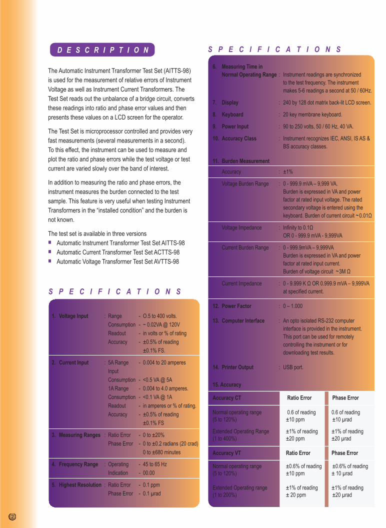
The Automatic Instrument Transformer Test Set (AITTS-98) is used for the measurement of relative errors of Instrument Voltage as well as Instrument Current Transformers. The Test Set reads out the unbalance of a bridge circuit, converts these readings into ratio and phase error values and then presents these values on a LCD screen for the operator.
The Test Set is microprocessor controlled and provides very fast measurements (several measurements in a second).To this effect, the instrument can be used to measure and plot the ratio and phase errors while the test voltage or test current are varied slowly over the band of interest.
In addition to measuring the ratio and phase errors, the instrument measures the burden connected to the test sample. This feature is very useful when testing Instrument Transformers in the “installed condition” and the burden is not known.
The test set is available in three versions■ Automatic Instrument Transformer Test Set AITTS-98 ■ Automatic Current Transformer Test Set ACTTS-98 ■ Automatic Voltage Transformer Test Set AVTTS-98
The CT/VT test systems are designed to test CTs over the range of 5 to 3200 amperes and Single Phase VTs over the range of 100 to 33000 volts. CTs of both 5A or 1A rating can be tested.
The system is self contained and includes the appropriate power supplies to generate the required test voltage & current, the appropriate reference CTs and VTs, a set of burdens to load the test CT/VT to the required rating and an automatic CT/VT comparator to measure the errors of the test specimen transformer.
CT demagnetizer is provided so that the CTs can be demagnetized prior to conducting the accuracy tests. The Automatic Instrument Transformer Test Systems can be designed to test CTs over a range of 5 to 6000A and Single Phase VTs over the range of upto 400kV.
1. Voltage Input : Range - O.5 to 400 volts. Consumption - ~ 0.02VA @ 120V Readout - in volts or % of rating Accuracy - ±0.5% of reading ±0.1% FS.
2. Current Input : 5A Range - 0.004 to 20 amperes Input Consumption - <0.5 VA @ 5A 1A Range - 0.004 to 4.0 amperes. Consumption - <0.1 VA @ 1A Readout - in amperes or % of rating. Accuracy - ±0.5% of reading ±0.1% FS
3. Measuring Ranges : Ratio Error - 0 to ±20% Phase Error - 0 to ±0.2 radians (20 crad) 0 to ±680 minutes
4. Frequency Range : Operating - 45 to 65 Hz Indication - 00.00
5. Highest Resolution : Ratio Error - 0.1 ppm Phase Error - 0.1 µrad
6. Measuring Time in Normal Operating Range : Instrument readings are synchronized to the test frequency. The instrument makes 5-6 readings a second at 50 / 60Hz.
7. Display : 240 by 128 dot matrix back-lit LCD screen.
8. Keyboard : 20 key membrane keyboard.
9. Power Input : 90 to 250 volts, 50 / 60 Hz, 40 VA.
10. Accuracy Class : Instrument recognizes IEC, ANSI, IS AS & BS accuracy classes.
11. Burden Measurement
Accuracy : ±1%
Voltage Burden Range : 0 - 999.9 mVA – 9,999 VA. Burden is expressed in VA and power factor at rated input voltage. The rated secondary voltage is entered using the keyboard. Burden of current circuit ~0.01Ω
Voltage Impedance : Infinity to 0.1Ω OR 0 - 999.9 mVA - 9,999VA
Current Burden Range : 0 - 999.9mVA – 9,999VA Burden is expressed in VA and power factor at rated input current. Burden of voltage circuit ~3M Ω
Current Impedance : 0 - 9.999 K Ω OR 0.999.9 mVA – 9,999VA at specified current.
12. Power Factor : 0 – 1.000
13. Computer Interface : An opto isolated RS-232 computer interface is provided in the instrument. This port can be used for remotely controlling the instrument or for downloading test results.
14. Printer Output : USB port.
15. Accuracy
Accuracy CT Ratio Error Phase Error
Normal operating range 0.6 of reading 0.6 of reading (5 to 120%) ±10 ppm ±10 µrad
Extended Operating Range ±1% of reading ±1% of reading(1 to 400%) ±20 ppm ±20 µrad
Accuracy VT Ratio Error Phase Error
Normal operating range ±0.6% of reading ±0.6% of reading (5 to 120%) ±10 ppm ± 10 µrad Extended Operating range ±1% of reading ±1% of reading (1 to 200%) ± 20 ppm ±20 µrad
16. Data Storage facility : Can store 80 readings – 40 readings each for CTs and VTs. Data is retained in memory even when the instrument is switched OFF.
17. Data Hold facility : At any given %of Voltage or Current, we can hold the readings displayed by pressing F1. To resume measurements, press F1 again.
18. Error Plotting : By Pressing F2 the instrument will plot Ratio and Phase Errors which are displayed on the LCD screen or on the connected PC. The graph can be printed only after it is transferred to the PC
19. PC Operation : Can be controlled from a PC using PC keyboard. Results are shown on PC monitor and test results can be transferred to the PC for data storage. Results are stored in pre-defined format or excel format.
20. Mechanical data Dimensions : 19-inch rack mount Weight : Approx 9 kgs.
21. Temperature : -10 to 50°C Humidity : Ambient to 90% RH

ELT
EL
* AP
R 2
013
Electronic Potential Divider (EPD) is an amplifier aided capacitive divider designed to operate at high voltages The EPD uses loss free high voltage reference capacitor externally for the high voltage arm of the divider. EPD along with Standard Capacitor will act as multi ratio Standard PT. Unlike other similar dividers, the EPD provides an isolated output whose output is related to the ratio setting. EPDs are used for accurate voltage measurement in metering circuits as well as for VT calibration. Advantages of using the Electronic Potential Divider as a Standard VT. - Provides flexibility of various VT ratios- Eliminates the need to have several Standard VTs - High Accuracy of measurement of class 0.05.
Eltel manufactures standard capacitors of 15kV & 33kV rating. Standard Capacitors are used as high voltage arm in voltage dividers for precision measurement of AC voltages, including peak and surge values, and for use when measuring the errors of Potential Transformers.
Manual & Automatic Transformer Ratio Meters. Digital Micro Ohm Meters with built in 100Amp source. Manual & Automatic Transformer Winding Resistance & On Load Tap Changer Test sets. Automatic CT/VT Test Sets & Systems. Automatic 12 kV & 5 kV Capacitance & Tan Delta Test Sets. Transformer Loss Measurement System. Relaying Current Transformer Analyser.
O T H E R P R O D U C T S
Burdens for IEC and ANSI specifications rated for various input voltages are available. The Potential Burdens are rated for continuous operation at 100% of rated voltage and for 200% intermittantly.
STANDARD CAPACITOR
Eltel manufactures Standard Current Transformers over a range of ratios and accuracies. Reference Standard CTs of 0.05 & 0.005 accuracies are available.
OPTIONAL ACCESSORIES FOR CT TESTING
STANDARD CURRENT TRANSFORMER
Burden for 1A and 5A for IEC and ANSI specifications are available.The Current Burdens are rated for continuous operation at 100% of rated current and for200% intermittently.
CURRENT TRANSFORMER BURDEN■ Automatic micro-processor controlled measurement. ■ Measures the total burden connected to the
test sample. ■ Plots ratio & phase errors on screen. ■ Digital display of test results on 240 x 128 dot matrix
back-lit LCD screen. ■ Keyboard entry of parameters.■ RS-232C computer interface
(Compatible with Windows XP-2000 & above). ■ USB printer port.■ Automatic ranging. ■ Voltage & Current Transformer testing with one
test set. ■ 5 & 1 Amp CT testing using either a 5 or 1 Amp
Standard CT. ■ Identifies ANSI, IEC, IEC-S, IEC-P, IS, IS-S, IS-P,
IS-PR, AS, AS-S, BS, BS-S standards for CT & VT. ■ Fast measurements-typically 5 readings per second. ■ Audible alarm for error message. ■ Data Hold & Data Storage Facility. ■ Ratio Correction Factor (ANSI).
ELECTRONIC POTENTIAL DIVIDER
POTENTIAL TRANSFORMER BURDEN
Works : Plot No. 39, KIADB Industrial Area, Veerapura, Doddaballapur, Bengaluru – 561 203. INDIA.TEL : 91-80-27630366, 27630367, 27630368, +91-9686693047, +91-9686693048 FAX : 91-80-27630351■ CHENNAI: 044-24339075 ■ GURGAON: 0124-2460619, 093115 42530 ■ KOLKATA: 033-24765536, 09331094257■ MUMBAI: 022 - 21713579, 09325885244 ■ VADODARA: 09327757574
311 EMBASSY CENTRE, CRESCENT ROAD, BENGALURU-560 001, INDIATEL. : 91-80-22255467, 22205686, 22284253, 22284298 FAX : 91-80-22252733E-mail: [email protected] Website: http//www.eltelindustries.com
An ISO 9001 - 2008 Certified Company