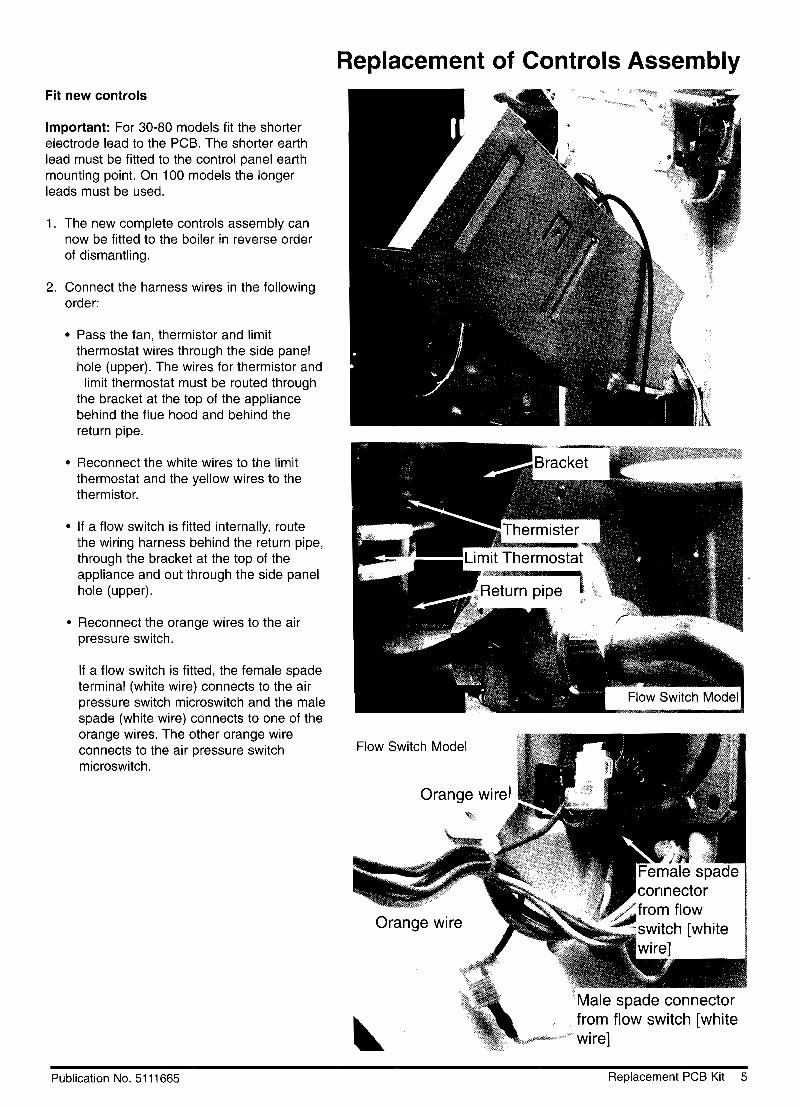
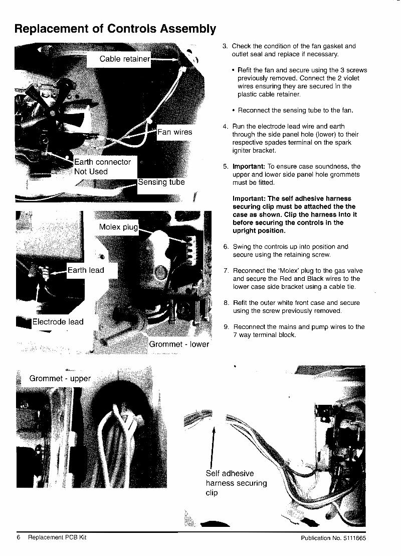
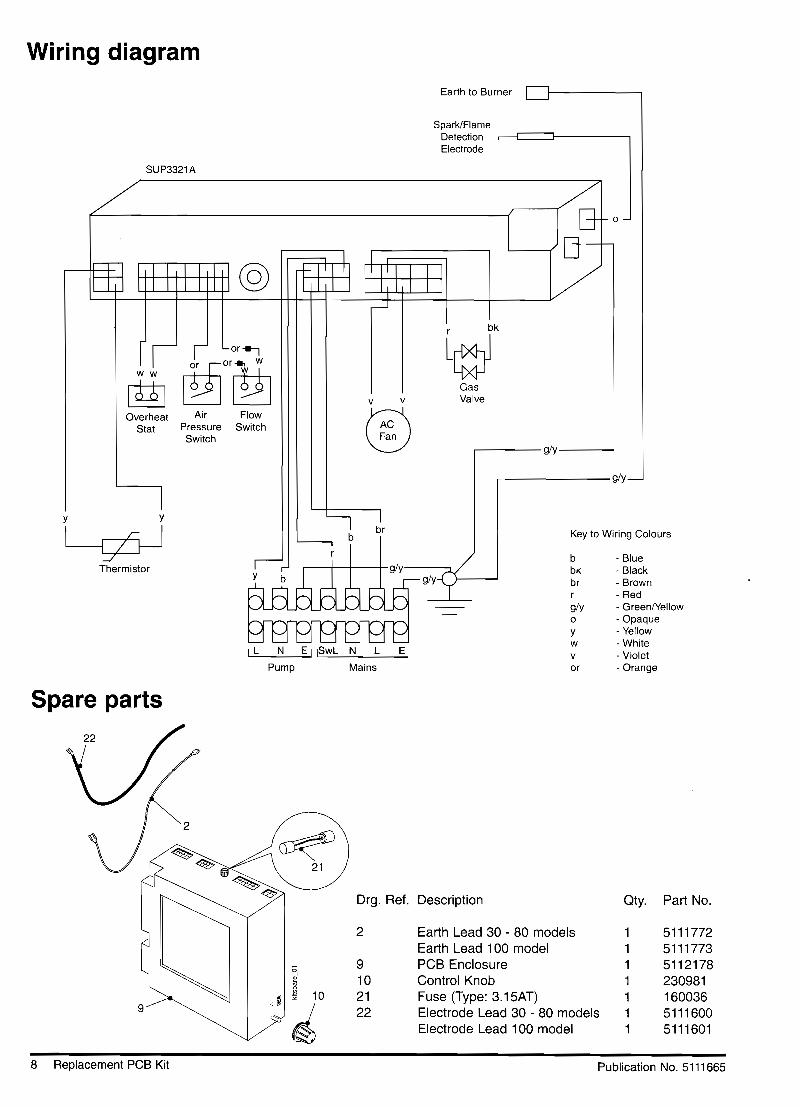
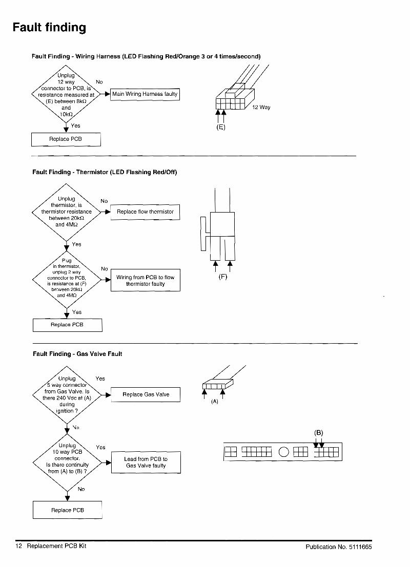
potterton - suprima 30 - 100l - free boiler manuals · sup0003a about the boiler see inside cover...
TRANSCRIPT

SU
P00
03A
About the Boiler See inside cover for models covered by these instructions.This is a Wall Mounted Fan Assisted Balanced Flue Gas Boiler.This boiler is for use with Natural Gas (G20) only at 20mbar and for use in GB & IE.
About Safety The Gas Safety (Installation and Use) Regulations 1998.
‘‘ In your own interest, and that of safety, it is law that all gas appliances are installed by competentpersons, in accordance with the above regulations. Failure to install appliances correctly couldlead to prosecution.’’
Installation must be in accordance with the Installation & Service Instructions and the rules inforce.
Leave these instructions and the Benchmark Log Book with the user for use on future calls.
Installation & Service Instructions Suprima30L - 100L
TM
The code of practice for the installation,commissioning & servicing of central heating systems
Suppli
ed
SupSSSSSSSuSuSuSuSuSuSuSupppplie
pplie
by
BenchmarBenchma
theman
ual
an
theheman
ual
nual
nualuuauauauauasli
brary.
c
ibslibrabrbrbrbrbrbrbbbbibibibibibib
ualsl
ibua
lslib
co.uk& Service InService
k Log Book wLog Boo
Publication No. 51026962
Contents
Contents
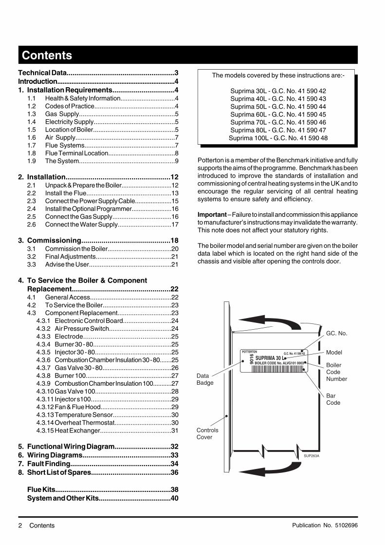
Technical Data........................................................3Introduction..................................................................41. Installation Requirements................................4
1.1 Health & Safety Information...............................41.2 Codes of Practice.............................................41.3 Gas Supply.....................................................51.4 Electricity Supply.............................................51.5 Location of Boiler..............................................51.6 Air Supply.......................................................71.7 Flue Systems..................................................71.8 Flue Terminal Location......................................81.9 The System.....................................................9
2. Installation...................................................122.1 Unpack & Prepare the Boiler.............................122.2 Install the Flue...............................................132.3 Connect the Power Supply Cable.....................152.4 Install the Optional Programmer.......................162.5 Connect the Gas Supply.................................162.6 Connect the Water Supply..............................17
3. Commissioning............................................183.1 Commission the Boiler....................................203.2 Final Adjustments..........................................213.3 Advise the User..............................................21
4. To Service the Boiler & ComponentReplacement.................................................224.1 General Access.............................................224.2 To Service the Boiler......................................234.3 Component Replacement..............................23
4.3.1 Electronic Control Board...........................244.3.2 Air Pressure Switch...................................244.3.3 Electrode..............................................254.3.4 Burner 30 - 80............................................254.3.5 Injector 30 - 80...........................................254.3.6 Combustion Chamber Insulation 30 - 80.......254.3.7 Gas Valve 30 - 80.......................................264.3.8 Burner 100................................................274.3.9 Combustion Chamber Insulation 100...........274.3.10Gas Valve 100...........................................284.3.11 Injector s100.............................................294.3.12Fan & Flue Hood........................................294.3.13Temperature Sensor.................................304.3.14Overheat Thermostat................................304.3.15Heat Exchanger........................................31
5. Functional Wiring Diagram.............................326. Wiring Diagrams.............................................337. Fault Finding....................................................348. Short List of Spares.........................................36
Flue Kits..............................................................38System and Other Kits......................................40
Potterton is a member of the Benchmark initiative and fullysupports the aims of the programme. Benchmark has beenintroduced to improve the standards of installation andcommissioning of central heating systems in the UK and toencourage the regular servicing of all central heatingsystems to ensure safety and efficiency.
Important – Failure to install and commission this applianceto manufacturer’s instructions may invalidate the warranty.This note does not affect your statutory rights.
The boiler model and serial number are given on the boilerdata label which is located on the right hand side of thechassis and visible after opening the controls door.
The models covered by these instructions are:-
Suprima 30L - G.C. No. 41 590 42Suprima 40L - G.C. No. 41 590 43Suprima 50L - G.C. No. 41 590 44Suprima 60L - G.C. No. 41 590 45Suprima 70L - G.C. No. 41 590 46Suprima 80L - G.C. No. 41 590 47Suprima 100L - G.C. No. 41 590 48
POTTERTON G.C. No. 41 590 42
9016
BOILER CODE No. ALVG101 0003SUPRIMA 30 L
SUP263A

Publication No. 5102696 3
Maximum Working Head 30.5 m (100 ft)Minimum Working Head 150 mm (6 in)
Gas Supply Pressure 20 mbarGas Supply Connection Rc. ½ (½ in BSP Female) (30 - 80 models)
15 mm copper tail (100 model)
Maximum Flow Temperature 82°CFlow/Return Connections 22 mm CopperWater Content 1.7 litres (0.37 gal) - 30, 40 & 50 Models
2.1 litres (0.46 gal) - 60, 70, 80 & 100 Models
Appliance Lift Weight 26.0 kg (57.3 lbs) - 30, 40 & 50 Models30.2 kg (66.6 lbs) - 60, 70 & 80 Models34.6 kg (76.3 lbs) - 100 Model
Appliance Weight 32.0 kg (70.0 lbs) - 30, 40 & 50 ModelsInstalled - Dry 35.4 kg (78.1 lbs) - 60, 70 & 80 Models
39.7 kg (87.5 lbs) - 100 Model
Electricity Supply 230v ~ 50Hz Fused at 3AInternal Fuse Type 3.15ATPower Consumption 80 Watts (excluding pump)Classifications CAT 1 2 H 2H G20 20 mbar IP20
C12, C32
Technical Data
Nominal Boiler Ratings
Technical Data
Boiler
models
Input Burner setting pressure Gas Rate
kW8.8
11.7
14.7
17.6
20.5
23.4
28.7
Btu/h30 000
40 000
50 000
60 000
70 000
80 000
98 000
Output
kW11.0
14.7
18.3
22.0
25.6
29.3
35.9
Btu/h37 500
50 000
62 500
75 000
87 500
100 000
122 500
in wg3.70
4.50
4.10
3.70
5.35
5.56
5.54
m³/h1.05
1.40
1.75
2.10
2.45
2.80
3.42
ft³/h37.1
49.3
61.8
74.2
86.4
98.7
120.9
Injector Size
mm dia.2.8
3.1
3.5
3.9
3.9
4.1
3.2
30
40
50
60
70
80
100
mbar9.3
11.2
10.3
9.2
13.4
13.9
13.6
SAFETY, PERFORMANCE & QUALITYSuprima boilers have been assessed by a Government appointed Notified
Body and shown to meet the 'Essential Requirements' of the European GasAppliance Directive.
The Directive lays down requirements for the safety and efficiency of theappliance, together with its design, construction, and use of materials.
It also requires the production process to be covered by an approved andmonitored system of quality assurance.
SEDBUK Declaration for Suprima
Model Seasonal Efficiency(SEDBUK) (%)
30L 78.040L 78.550L 78.160L 78.170L 78.680L 78.8100L 78.0
This value is used in the UKGovernment's Standard AssessmentProcedure (SAP) for energy rating ofdwellings. The test data from which ithas been calculated have been certifiedby 0063.

Publication No. 51026964
Introduction
Introduction/Installation Requirements
Gas Safety (Installation & Use) Regulations 1998.
This appliance must be installed and serviced by a competentperson, in accordance with the above regulations.
In the UK 'Corgi' Registered Installers (including the regionsof British Gas Plc) undertake to work to a safe andsatisfactory standard.
Failure to install appliances correctly could lead toprosecution.
It is in your own interest, and that of safety, to ensure thatthe regulations are complied with.
Suprima boilers are fully automatically controlled, wallmounted, fan powered, balanced flue appliances using acast iron heat exchanger and are available in outputsranging from 8.8 - 28.7 kW (30,000 - 98,000 Btu/h)
The boilers are designed for use on fully pumped openvented or sealed water systems with an indirect hot watercylinder.
THEY MUST NOT BE CONNECTED TO A DIRECTCYLINDER.
The boilers are for use on Natural Gas (G20) only.
Samples of the Suprima gas boilers have been examinedby Gastec, a United Kingdom Notified Body. The range iscertified to comply with the essential requirements of theGas Appliance Directive 90/396/EEC, the Low VoltageDirective 72/23/EEC and shows compliance with the ElectroMagnetic Compatibility Directive 89/336/EEC, the BoilerEfficiency Directive 92/42/EEC and are therefore permittedto carry the CE Mark.
Delivery & Kits Available
The unit is delivered in two packages (1) the boiler withfittings and (2) the flue/terminal assembly. See pages 38 &39 for flue options.
Various kits are available for the Suprima range of boilers,see pages 40 & 41.
1. Installation Requirements
1.1 Health and Safety Information for theInstaller and Service Engineer
Under the Consumer Protection Act 1987 and Section 6 ofthe Health and Safety at Work Act 1974, we are required toprovide information on substances hazardous to health.
Small quantities of adhesives and sealants used in theproduct are cured and present no known hazards.
The following substances are also present.
Insulation and Seals
Material - Man Made Mineral Fibre.
Description - Boards, Ropes, Gaskets.
Known Hazards - Some people can suffer reddeningand itching of the skin. Fibre entry into the eye willcause foreign body irritation which can cause severeirritation to people wearing contact lenses. Also irritationto respiratory tract.
Precautions - Dust goggles will protect eyes. Peoplewith a history of skin complaints may be particularlysusceptible to irritation. High dust levels are only likelyto arise following harsh abrasion. In general, normalhandling and use will not present high risk, follow goodhygiene practices, wash hands before touching eyes,consuming food, drinking or using the toilet.
First Aid - Medical attention must be sought followingeye contact or prolonged reddening of the skin.
1.2 Codes of Practice
The boiler must be installed in accordance with: The GasSafety (Installation and Use) Regulations 1998 and thecurrent issue of:-
The Building Regulations, Building Standards (Scotland)Regulations, Local Building Regulations, Model and localWater Undertaking Bye-laws, IEE Wiring Regulations andHealth & Safety Document No. 635 "The Electrician AtWork Regulations 1989".
Publication No. 5102696 5Installation Requirements
1.3 Gas Supply
The meter and supply pipes must be capable of delivering this quantity of gas in addition to the demand from any otherappliances in the house and must be governed at the meter.
The complete installation must be tested for gas soundness and purged as described in BS6891.
1.4 Electricity Supply
230V ~ 50Hz via a fused double pole switch with a contact separation of at least 3 mm in both poles adjacent to the boiler.Power consumption is approximately 150W (inc. pump). There must be only one common isolator for the boiler and its controlsystem and it must provide complete electrical isolation.
Fuse the supply at 3 A. The minimum requirement for the power supply cable is that it should be a PVC sheathed cord atleast 0.75 mm² (24 x 0.2 mm) (code designation HO5 VV-F or HO5 VVH2-F) as specified in table 16 of BS6500:1984.
All wiring external to the boiler shall comply with the latest IEE Wiring Regulations, and any local regulations which apply.
WARNING: THIS APPLIANCE MUST BE EARTHED.
In the event of an electrical fault after installation of the boiler, preliminary electrical systems checks must be carried out i.e.Earth Continuity, Short Circuit, Polarity and Resistance to Earth.
1.5 Location of Boiler
The boiler is not suitable for external installation unless it is suitably protected.
If the sealed system kit is being used, this should be installed first. See instructions supplied with kit.
The boiler must be installed so that the flue terminal is exposed to the external air. It is important that the position of the terminalallows the free passage of air across it at all times.
The boiler must be mounted on a flat wall which is sufficiently robust to take the weight of the boiler.
The boiler is suitable for installation to a combustible wall e.g. wood cladding, provided that the flue duct is not closer than25 mm to combustible material. A metal sleeve should be installed to surround the flue duct to provide a 25 mm annular space.Further guidance is given in BS5440:1:2000, sub-clause 4.4.
If the boiler is to be installed in a timber framed building it should be fitted in accordance with the Institute of Gas Engineersdocument IGE/UP/7/1998 (also, British Gas Service publication Part 19 - Building and Kitchen Work). If in doubt advice mustbe sought from Potterton.
The boiler may be installed in any room, although particular attention is drawn to the requirements of the current IEE WiringRegulations and, in Scotland, the electrical provisions of the Building Standards applicable in Scotland with respect to theinstallation of the boiler in a room containing a bath or shower. Where a room-sealed appliance is installed in a room containinga bath or shower, any electrical switch or appliance control, utilising mains electricity should be so situated that it cannot betouched by a person using the bath or shower.
Where the installation of the boiler will be in an unusual position, special procedures may be necessary and BS6798 andBS5546 give detailed guidance on this aspect.
A cupboard or compartment used to enclose the boiler must be designed and constructed specifically for this purpose.An existing cupboard or compartment may be used provided that it is modified for the purpose. Details of essential featuresof cupboard/compartment design including airing cupboard installations are given in BS6798 and BS5546 and should becomplied with.
The boiler requires only the clearances shown on Page 6, after installation.

Publication No. 51026966 Installation Requirements
Fig. 1

Publication No. 5102696 7
1.6 Air Supply
The air requirements must meet BS 5440 Part 2.The room in which the boiler is installed does not require a purpose provided air vent.
1.6.1 Ventilated Cupboard/Compartment: If the boiler is installed in a cupboard or compartment (with the exceptionof those installations covered by Section 1.6.2), permanent air vents are required in the cupboard or compartment,one at high level and one at low level, either direct to the outside air or to a room. Both high level and low level airvents must communicate with the same room or must be on the same wall to outside air. Both the high level andlow level vent must each have a free area as stated below. The free area of each vent may be halved if theventilation is provided directly from outside.
Models: 30: 99 cm² 40: 133 cm² 50: 169 cm²60: 198 cm² 70: 231 cm² 80: 264 cm² 100: 323 cm2
If the boiler is installed in a cupboard or compartment with a door, allow at least 15 mm clearance between thefront of the boiler and the door for air movement.
1.6.2 Unventilated Compartment: The 30, 40 and 50 models can be installed in an unventilated compartmentproviding the following conditions are met and no other heat sources are present within the compartment:
Maximum Horizontal flue length from turret: 560 mmMinimum clearances for alternative configurations
Front 280 mm or Front 490 mmSide 75 mm Side 175 mmBottom 250 mm Bottom 100 mmTop 450 mm Top 265 mm
1.7 Flue Systems
Horizontal • The flue/terminal assembly supplied is suitable for a wall thickness of between 150 mm and 300mm.
• A flue/terminal assembly suitable for a wall thickness of up to 550 mm is also available.• Both the flue/terminal assemblies are telescopic and the minimum lengths (150 mm/6 in) are
achieved by cutting. Ensure that the same length is removed from the inner and outer tubes tomaintain a 20 mm overlap (minimum).
• 1 m flue extensions are available.• Under no circumstances should the total flue length exceed - 3.4 m, 30 - 80 models.
- 0.68 m, 100 model No bendsallowed.
Vertical 1. Twin Tube system, 30 - 80 models only.Maximum actual length 7 m (7 extensions)Maximum equivalent resistance = 7 m
2. Vertical Concentric system.30 - 80 models - Maximum actual length 3.4 m, equivalent resistance = 3.4 m.100 model - Maximum actual length 1.4m, No bends allowed.
Combination Flue System
• Combined horizontal & vertical concentric system for 30 - 80 models only.Maximum actual length 3.4 m, maximum equivalent length 3.4 m.
Note: All flue lengths quoted refer to straight lengths. For the effects of bends and offsets see Section 2.2 'Install theFlue' or the appropriate flue instructions.
Installation Requirements

Publication No. 51026968
• Where a horizontal flue is sited less than 2mabove a balcony, above ground, or above a flatroof to which people have access, a suitableterminal guard must be fitted. This serves twopurposes, to protect the terminal against damageor interference and to protect passers-by. Aterminal guard is available (Sales Code:PTERMGUARDEF), this should be fitted centrallyabout the terminal.
Note: Where a flue terminal is installed less than1 metre from a plastic, or painted gutter, or 500mm from painted eaves, an aluminium shield 1metre long, should be fitted to the underside of thegutter or painted surface. A suitable wall plateshould be fitted to the painted wall surface of amobile home.
• IMPORTANT: It is absolutely ESSENTIAL, toensure that products of combustion dischargingfrom the terminal cannot re-enter the building, orany other adjacent building, through ventilators,windows, doors, natural air infiltration, or forcedventilation/air conditioning. If products ofcombustion are found to be re-entering any building,the appliance MUST be turned OFFIMMEDIATELY.
1.8 Flue Terminal Location
Installation Requirements
Fig. 2
M
G
G
H
F
L
G
AA
F
J
K,N
DE
J
Likely flue positions requiring a flue terminal guard
C
Q
AG
K,N
G
FLU
0002
A
P
S
R
Fanned Draught Balanced Flue
A Directly below an opening, air brick,opening window etc
B Above an opening, air brick, opening window, etcC Horizontally to an opening, air brick,
opening window etcD Below a gutter, or sanitary pipeworkE Below the eavesF Below a balcony or carport roofG Above ground, roof or balcony levelH From vertical drain/soil pipe workJ From an internal or external cornerK From a surface facing a terminalL Vertically from a terminal on the same wallM Horizontally from a terminal on the same wallN From a terminal facing the terminalP From an opening in a carport (e.g. door, windows)
into the buildingQ From adjacent wall to flue (vertical only)R From internal corner to flue (vertical only)S Below eaves or balcony (vertical only)
Terminal Position with Minimum Distance (mm)
Note: The distance from a fanned draught appliance terminal installedparallel to a boundary may not be less than 300 mm in accordance withthe diagram on the left.
300
300300
75200200300150300600
1500300
12001200
210230600
Top View Rear Flue Top View Side Flue
TerminalAssembly
Property Boundary Line
Fanned DraughtFanned Draught
300 min. 300 min.
FLU
0005A
Reduced Clearances
This range of boilers has been tested and approved for use with certainclearances less than those shown above.
Only one of these reductions may be used on a single installation.
D Below a gutter, or sanitary pipework 25E Below the eaves 25F Below a balcony or carport roof 25H From vertical drain/soil pipe work 25J From an internal or external corner 25

Publication No. 5102696 9Installation Requirements
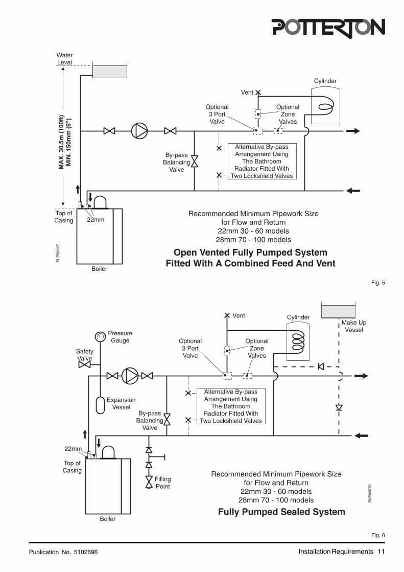
1.9 The System
Before installing a new boiler to an existing system treat thesystem with an appropriate descaling/flushing agent as perthe instructions supplied with the treatment package. It isrecommended that any corrosion inhibitors and descalers/flushing agents used are manufactured by Fernox orBetzDearborn.
If plastic pipe is used for the central heating circuit theremust be a run of at least 2m of uninsulated copper pipe fromthe boiler flow and return connections.
The boiler must be used on Indirect Fully Pumped systemsonly, which may be sealed or open vented - See Page 12for pump requirements.
The system should be designed so that the maximum statichead does not exceed 30.5 m (100 ft) and a minimum of 150mm (6 in). The flow pipe from the boiler must always be levelto or higher than the return pipe.
On all systems the pump live connection should be wiredto the boiler terminal block, it will then be controlled by thepump over-run. This will ensure that the pump will continueto run after boiler shut down if the water temperature is high,thus preventing nuisance operation of the overheatthermostat.
It is important that where electrically operated zone valvesare used the boiler is wired so it does not cycle when thezone valves are closed. Also, systems fitted with controlsthat close both hot water and central heating circuits whilethe boiler is still hot, must be fitted with a by-pass circuit todissipate the residual heat from within the boiler.
If a three port valve is used as shown in Fig. 5 a by-pass isnot necessary since one circuit is always open.
Where a pair of two port valves are used, a by-pass isnecessary. The total length of the by-pass circuit takenfrom the boiler connections should be greater than 4 metresof 22 mm pipe. It should be fitted with a lockshield valve andbe adjusted to maintain a minimum flow through the boilerof 4.5 litres/min (1 gal/min).
Systems fitted with controls which allow the boiler tooperate when both the hot water and central heating circuitsare closed (i.e. mechanically operated thermostatic controlvalves) must be fitted with a by-pass circuit (2 m min. lengthof 22 mm dia. pipe) and capable of maintaining a minimumwater flow rate through the boiler of 9 litres/min (2 gal/min).
A suggested method of meeting these requirements byusing a bathroom radiator fitted with two lockshield valvesis shown in Fig. 5. Additional system information can befound in the Control Systems, pipework and Wiring Guide.Drain off taps should be fitted in the pipework close to theboiler and in the low points of the system.
Note: Although the system can be emptied using the drainoff taps installed in the pipework around the system, toempty the boiler it is necessary to remove the drain offscrew positioned on the heat exchanger.
Sealed Systems
Note: If the sealed system kit is Not being used theinstallation must comply with the following requirements.
InstallationThe installation must comply with the requirements of BS6798: 1987 and BS 5449: Pt 1. The British Gas publication"British Gas Specification for Domestic Wet Central HeatingSystems" should also be consulted.
Pressure Relief ValveA non-adjustable spring-loaded pressure relief valve, presetto operate at 3 bar (45lbf/in²) shall be used. It must complywith BS 6759: Pt 1. and include a manual testing device. Itshall be positioned in the flow pipe either horizontally orvertically upwards and close to the boiler. No shut-off valvesare to be placed between the boiler and the safety valve. Thevalve should be installed with a discharge pipe whichpermits the safe discharge of steam and hot water such thatno hazard to persons or damage to electrical componentsis caused.
Pressure GaugeA pressure gauge incorporating a fill pressure indicator,covering the range 0 - 4 bar (60 lbf/in²) shall be fitted to thesystem. It should be connected to the system, preferably atthe same point as the expansion vessel. Its location shouldbe visible from the filling point.
Expansion VesselA diaphragm type expansion vessel to BS 4814: Pt 1. shallbe fitted close to the inlet side of the pump. The connectingpipework should not be less than 15 mm. Pipeworkconnecting the expansion vessel should not incorporatevalves of any sort. Methods of supporting the vessel aresupplied by the vessel manufacturer. The nitrogen or aircharge pressure of the expansion vessel shall not be lessthan the hydrostatic head, (height of the top point of thesystem above the expansion vessel). To size the expansionvessel it is first necessary to calculate the volume of waterin the system in litres. The following volumes may be usedas a conservative guide to calculating the system volume.
Boiler Heat Exchanger: 2.1 litresSmall Bore Pipework: 1 litre per kW of system
outputMicro Bore Pipework: 7 litresSteel Panel Radiators: 8 litres per kW of system
outputLow Water Capacity Radiators: 2 litres per kW of system
outputHot Water Cylinder: 2 litres

Publication No. 510269610
CylinderThe hot water cylinder must be an indirect coil type or adirect cylinder fitted with an immersion calorifier suitable foroperating at a gauge pressure of 0.3 bar (5 lbf/in²) in excessof safety valve setting. Single feed indirect cylinders are notsuitable for sealed systems.
Method of Make-up for sealed systemsProvision shall be made for replacing water loss from thesystem either:-
i) from a make-up vessel or tank mounted in a positionhigher than the top point of the system, and connectedthrough a non-return valve to the system on thereturn side of the hot water cylinder or the return sideof all heat emitters, see Fig.6.
or
ii) where access to a make-up vessel would be difficultby using the mains top up method or a remoteautomatic pressurisation and make-up unit as shownin Figs. 3 & 4.
Mains ConnectionThere shall be no connection to the mains water supply orto the water storage tank which supplies domestic hot watereven though a non-return valve, without the approval of theLocal Water Authority.
Filling PointThe system shall be fitted with a filling point at low levelwhich incorporates a stop valve to BS 1010 and a doublecheck valve of an accepted type to be fitted in this orderfrom the system mains, see Fig. 3.
1.5
1.0
V x 0.087
Vessel Charge Pressure (bar)
Initial System Pressure (bar)
Expansion Vessel Volume (litres)
0.5
1.0
V x 0.11
Table 1.
If the system is extended, the expansion vessel volumemay have to be increased unless provision has been madefor extension. Where a vessel of the calculated size is notavailable, the next available larger size should be used.The boiler flow temperature is controlled at approximately82°C. The vessel size can now be determined from theinformation in Table 1 where V = System volume in litres.
Fig. 4
Fig. 3
Installation Requirements
Publication No. 5102696 11
Fig. 5
Fig. 6
Installation Requirements

Publication No. 510269612 Installation Requirements/Installation
Circulation Pump Selection
The resistance through the heat exchangerwhen operating with a water flow rate producingan 11°C temperature rise at maximum boileroutput are shown in the table. If other controlssuch as three position valves are used in thesystem, the resistance through them, quoted intheir manufacturers literature must be takeninto account. The pump may be fitted on eitherthe flow or return and MUST be wired directly tothe boiler terminal block. It must be fitted withtwo isolating valves which are positioned asclose to the pump as possible. Closing of anyvalve must always leave the open ventunobstructed.
Water Flow Rate Boiler Resistance
l/min
11.5
15.2
19.2
22.9
26.7
30.5
37.4
mbar
17.5
35.3
44.9
59.5
80.9
105.3
147.0
m
0.18
0.36
0.46
0.61
0.83
1.08
1.50
30
40
50
60
70
80
100
2. Installation
2.1 Unpack & Prepare the Boiler
These instructions assume you have decided on where the boiler will be located and the type of flue system to be used.1. Carefully unpack the boiler.2. Do not discard any packaging until all the items are accounted for.3. Open the controls cover, remove the securing screw and washer, pull off the controls cover and put safely aside.4. Remove two screws and washers, remove the white front case and put safely aside.5. Place the mounting template in the proposed boiler position ensuring that it is level. Minimum clearances are accounted
for on the template.6. Mark the flue hole, remove the template and carefully cut the flue hole through the wall.

Publication No. 5102696 13Installation
Boiler
Boiler Securing Point
Flue TubeMinimum Clearance
SU
P00
10B
410mm Minimum Clearance
660m
m M
inim
um C
lear
ance
LiteraturePack
fdthyjkllkhklkyj
fdthyjkllkhklkyj
fdthyjkllkhklkyj
fdthyjkllkhklkyj
F
R
BoilerMountingBracket
FixingsPoly Bag
BoilerSecuring
Clip
BoilerMountingBracket
WallTemplate
Fig. 7
7. Replace the template centrally over the hole(ensure template is level), mark two screwfixing hole positions for the mounting bracketand one for the securing point.
8. Remove the template, drill (7 mm drill) andplug the three holes.
9. Secure the mounting bracket to the wallusing two No. 12 x 2" woodscrews.
10.Lift the boiler onto the mounting bracket,slide both boiler securing clips over themounting bracket (this prevents the boilerfrom being accidently lifted off the themounting bracket), see Fig.7.To square the boiler to the wall adjust theboiler alignement screws on the back panelof the boiler.
11.The third screw provided is also to preventthe boiler from being lifted off the mountingbracket, once the boiler is mounted on thewall. This screw can be replaced by ananti-theft kit see note below.
Note: There is provision for an anti-theft securingpoint (sales code: SUPKITP) which may beused if required.
2.2 Install the Flue
Maximum equivalent flue lengths are asfollows: 30 - 80 Models - 3.4m, 100 Model -0.68m (no bends allowed).
These instructions are for rear and side flueapplications.
Rear Flue1. Measure the wall thickness and add
66mm (or 106mm for installations usingthe System Boiler or Stand Off Kits).
Side Flue1. Determine the X dimension (wall thickness
+ distance to boiler centreline).For both Rear & Side Flues2. Extend the telescopic flue to the required
length, minimum 20 mm overlap.3. Drill through the pilot hole and secure with
self tapping screw.4. Wrap tape around the joint on the outer
duct to seal the flue, slide drip ring into aposition to coincide with the air gap in thewall (cavity wall).
5. Slide the flue through the hole until it stopson the pin.
6. The boiler is supplied with the flue elbowset to the rear. For side outlet slacken thescrews and turn the elbow to the requiredposition and re-tighten screws. Ensurethat the seals are still correctly located.

Publication No. 510269614 Installation
7. Slide the flue back until it engages in theelbow bayonet connection, twist anti-clockwise to lock.
8. Drill through pilot hole and lock flue inposition with the self tapping screwprovided.
9. Make good the wall around the flue, bothoutside and inside.
For extension kits refer to pages 38 & 39. If aHorizontal Extension is required this MUST becombined with a Standard Flue as shown belowin the Maximum Flue Length Guide.
If a in-line bend is required in the flue thefollowing rules apply:
A 90° in-line bend is the equivalent to a 1mlength of flue.
A 135° in-line bend is the equivalent to a ½mlength of flue.
The maximum equivalent flue resistanceallowed when using bends is:30-80 models - 3.4m, 100 model - not allowed.
Note: For flue lengths less than the minimumtelescopic length, the tubes can be cut to suit.Ensure that the same length is removed fromthe inner and outer tubes to maintain a 20 mmoverlap (minimum).
For further information see the publicationssupplied with the flue system.
Fig. 8

Publication No. 5102696 15
PIN
87AR
XXX POTTERTON G.C. No. 41 590 42
Input (GROSS) Q = 11.0037500
kWBtu/h
8.8030000
kWBtu/h
9.303.70
mbarin. wg
1.0537.10
cu. m/hcu. ft/h
Output P =
Burner Pressure (HOT)
Gas Rate
Injector Size 2.8mm Dia.Type - C C C PMS = 3.0 bar
230V ~ 50Hz.80W 3A Fuse
THIS APPLIANCE IS INTENDED EXCLUSIVELY TOBE INSTALLED ON A SUPPLYWITH A GOVERNED METER
Baxi Heating Ltd.5105714
COUNTRY OF DESTINATION - GB, IE.
01
0086
IP 20
NO x CLASS 3
9016
BOILER CODE No. ALVG101 0003SUPRIMA 30 L
12 32
2H2H - G20 - 20 mbar
71
SUP0262B
Installation
Fig. 9
2.3 Connect the Power SupplyCable
1. Cable clamping is provided on the front ofthe controls panel. Feed the cables up andover the back of the chassis, through theclamp and into the terminal connection.Connect the wires, brown to L, blue to N and
green/yellow to earth ( ).
Note: When connecting the power supplycable, ensure that the length of the earthwire is such, that if the power supply cablepulls out of the cable clamp the live andneutral wires become taut before the earthwire.
2. The pump wiring should be routed throughthe hole in the base of the rear cover,through the cable clamp and connected tothe terminal connection.
3. Take up excess slack in the cables betweenthe terminal block and the cable clamp,then tighten the cable clamp screws.Ensure sufficient slack is available to thecable clamps to allow the control panel tohinge freely. Check by opening the controlpanel.If fitting the optional integral programmer goto section 2.4 before performing steps 4and 5 below.
4. Secure the controls assembly to the chassisusing the screw previously removed.
5. Carry out preliminary electrical systemchecks i.e. Earth Continuity, Short Circuit,Polarity and Resistance to Earth.
Frost Thermostat:If a Frost Thermostat is to be fitted, theconnections should be made in the wiringexternal to the boiler.The Frost Thermostat should be connectedbetween the Permanent Live & Switch Livein the mains terminal block on the boiler.
Do not switch on the electricity supply atthis stage.

Publication No. 510269616
Fig. 10
Fig. 11
Installation
2.4 Install the OptionalProgrammer
1. Install the programmer as shown in theinstructions supplied with it.
2.5 Connect the Gas Supply
Ensure that the gas supply is isolated. Connectthe gas supply using a suitable adaptor to thegas valve or 15 mm copper tail (100 model).
Important:To prevent damage to the 'O' ring,
do not solder the fittingwhilst assembled to the gas valve.
The pipe diameter required will depend on theboiler model and the pipe length from the gasmeter. Ensure that the gas supply pipe isselected in accordance with BS 6891 so that anadequate gas supply to the boiler is provided.
Do not turn the gas supply on at this stage.
FrontView
28
20100
SU
P00
21B
40
85
28
GasValve
All Dimensionsin mm
When SolderingRemove 'O' Ring
Side View
DO NOTSolder The
Fitting WhilstAssembled ToThe Gas Valve
Fitting
GasValve
Closed Open
Gas Valve Gas Valve
SecuringScrews
Gas CockRc ½"
½" B.S.P.Female
100 model 30 - 80 models
Publication No. 5102696 17
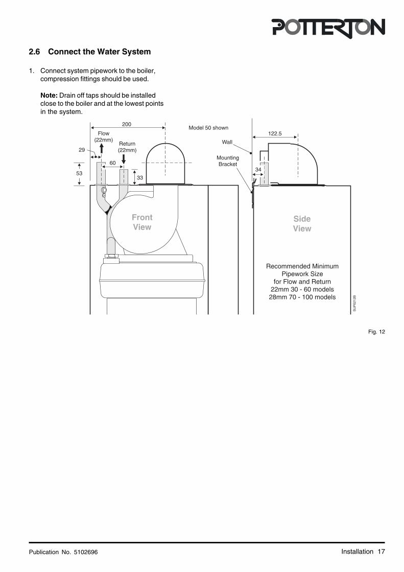
Fig. 12
Installation
2.6 Connect the Water System
1. Connect system pipework to the boiler,compression fittings should be used.
Note: Drain off taps should be installedclose to the boiler and at the lowest pointsin the system.

Publication No. 510269618
3. Commissioning
Fig. 13
Commissioning
PIN
87AR
XXX POTTERTON G.C. No. 41 590 42
Input (GROSS) Q = 11.0037500
kWBtu/h
8.8030000
kWBtu/h
9.303.70
mbarin. wg
1.0537.10
cu. m/hcu. ft/h
Output P =
Burner Pressure (HOT)
Gas Rate
Injector Size 2.8mm Dia.Type - C C C PMS = 3.0 bar
230V ~ 50Hz.80W 3A Fuse
THIS APPLIANCE IS INTENDED EXCLUSIVELY TOBE INSTALLED ON A SUPPLYWITH A GOVERNED METER
Baxi Heating Ltd.5105714
COUNTRY OF DESTINATION - GB, IE.
01
0086
IP 20
NO x CLASS 3
9016
BOILER CODE No. ALVG101 0003SUPRIMA 30 L
12 32
2H2H - G20 - 20 mbar
71
30 L ModelShown
50 L ModelShown
GasValve50 L
ModelShown
SU
P26
4A
Gas Pressureadjuster

Publication No. 5102696 19
Fig. 14
Commissioning
ImportantWhen checking for gas soundness open
all windows and doors in the room.Extinguish all naked lights, cigarettes, pipes, etc.
ImportantThe commissioning and boiler adjustment must
only be carried out by a suitably qualifiedpersonnel. Potterton offer this service on a
chargeable basis.
Gas Pressureadjuster
100 model shown
Publication No. 510269620
3.1 Commission the Boiler
Commissioning
Open Vented Systems - Remove the pump and flushthe system thoroughly with cold water. Re-fit the pump.Fill and vent the system then check for leaks.
Sealed Systems - Remove the pump and flush thesystem thoroughly with cold water. Re-fit the pump. Filland vent the system until the pressure gauge registers1.5 bar (21.5 lbf/in²) and check for leaks.
IMPORTANT: The pressure relief valve is factory testedand does not need testing during the commissioning ofthe boiler. It must not be used to reduce systempressure as it may cause debris in the system to foul thevalve.
All Systems
Warning: Before lighting the boiler, ensure that theouter white case has been correctly fitted and thatthe sealing strip fitted to the outer white case isforming a tight seal with the main boiler chassis.The controls cover is left off at this stage.
Preliminary electrical system checks
These checks must be carried out before attempting tolight the boiler.
They are:- Earth Continuity, Short Circuit, Polarity& Resistance to Earth.
Commission
1.The whole of the gas installation must be checkedfor soundness and purged in accordance with BS6891.
2. Set the boiler temperature control knob to 'O'Standby.
3. Turn the boiler gas service cock to the 'On' positionand ensure that the main gas supply is turned 'On'.
4. Make sure that the system is full of water and that thepump and radiator isolating valves are open. Ventair from the system.
5. Ensure that the main electricity supply is 'On'.
6. Check that the time control, if fitted, is in an 'On'position and that the room and cylinder thermostat,where fitted are set to high temperatures.
First time lighting:
7. Set the temperature control knob to its maximumsetting. The boiler will attempt to light, if the boilerdoes not light within 3 attempts (due to air in thesystem) the boiler controls will go to 'Lockout' and theupper Red LED on the control panel will go to a rapidflashing mode. To re-start the lighting sequence pressthe reset button on the control panel. There will be ashort delay before the lighting sequence starts.
When the burner flame has established lower Green LEDon the user control panel will be on continuously.
LED Indicators
Status Green LED Red LED
Mains ON Only OFF ON
Ext. Call for Heat FLASHING ON(Boiler set to STNDBY, 2 Per Sec.Temp. Control set to 'O' Off)
Ext. Call for Heat FLASHING OFF(STNDBY switch to ON, 2 Per Sec.Temp. Control set to Max.)
Ignition FLASHING OFF(i.e. Gas and Sparks ON) 16 Per Sec.
FLAME Detected ON OFF
Boiler Temperature FLASHING ONControl Satisfied 2 Per Sec.
8. With the main burner running, check for gassoundness using leak detection fluid.
9. Allow the system to reach maximum workingtemperature and examine for water leaks. Set thetemperature control to 'Standby' and drain the systemwhilst still hot.
Note: Should the boiler fail to operate correctly refer tothe Fault Finding Guide and the boiler wiring diagram forfurther information.
10. Re-fill and vent the system making a final check for leaks.
11. On sealed systems adjust to the correct cold fill pressure. Set the pressure gauge pointer to the system design pressure.
12. If a by-pass circuit is fitted the by-pass valve should be adjusted so as to maintain sufficient water flow through the boiler to ensure that the overheat thermostat does not operate under normal conditions.
Publication No. 5102696 21
13. If the boiler fails to operate
Check the LED indicator fault modes below and refer tofault finding guide and boiler wiring diagram.
LED Indicators Fault Modes
Status Green LED Red LED
Blocking - Mains Frequency ON FLASHINGincorrect or Air Switch Fault 2 Per Sec.> 1 min. or Reset button heldin to force a restart
Earth Fault or FLASHING FLASHINGMains Reversal 2 Per Sec. 2 Per Sec.
Lockout OFF FLASHING2 Per Sec.
3.2 Final Adjustments
1. Use a pressure gauge to check the inlet and burnerpressures. See the Data Badge for figures.
2. Turn the boiler on and allow to run for 10 minutes.
3. Check that the inlet pressure is 20mbar.
4. Check that the burner pressure is in accordancewith the information on the boiler data badge. Thegas valve is factory set, but if adjustment is requiredfollow Section 4.3.7 or 4.3.10.
5. Check at the gas meter that the gas rate is correct.
6. Set the temperature control knob to 'O' Standby andcheck that the main burner shuts down. Remove thepressure gauges, re- fit the screws and check for gassoundness.
7. Re-fit the controls cover and secure with the screwpreviously removed.
Control Thermostat
At its minimum and maximum settings, the thermostatshould control the water flow temperature atapproximately 57 °C - 82 °C.
Overheat Thermostat
The overheat thermostat is pre-set and no adjustmentis possible. It will require manual re-setting if anoverheat condition occurs (the LED will go to flashingRed).
The re-set button is located on the controls assembly.
Commissioning
Other Boiler Controls
No further setting or checking is necessary as allboiler mounted controls are designed so that if afault should occur they will fail safe.
External Controls
Check that any other external controls connected inthe system, such as clocks or thermostats, controlthe boiler are set as required.
3.3 Advise the User
On completion of the installation, the installer shoulddemonstrate the operation of the boiler and its associatedcontrols. Also hand over all the instructions.
1. If a programmer is fitted, set the time and programmethe required settings as shown in the instructionssupplied with the programmer.
2. Advise the user of the precautions necessary toprevent damage to the system and to the building inthe event of the system remaining inoperative duringfrost conditions.
3. Advise the User that for continued efficient and safeoperation of the boiler it is important that adequateservicing is carried out at least once a year by aPotterton Service Engineer, the local Gas Supplieror a C.O.R.G.I. Registered Installer.
4. Leave a permanent card attached to the boilergiving:
a. Name and address of installer.
b. Date of installation.
c. A wiring diagram of the external control circuit.
5. And finally, complete the Benchmark Log Book andhand over all the instructions supplied.

Publication No. 510269622
4. To Service the Boiler & Component Replacement
• To ensure continued efficient operation of the appliance, it is recommended that it is checked and cleaned asnecessary at regular intervals.
• The frequency of servicing will depend upon the particular installation conditions and usage but in general once peryear should be adequate.
• It is the law that any service work must be carried out by a competent person who is C.O.R.G.I. Registered.
• Before servicing, fire the appliance and check that the flames are blue and stable. Yellow flame and excessive liftingindicate poor combustion.
• WARNING: Before commencing work turn the temperature control knob to 'O' Off and allow the appliance tocool, isolate the electricity supply.
• If the gas valve is to be removed turn off the gas supply at the appliance service cock.
• IMPORTANT: Always test for gas soundness after completing any servicing of gas carrying components andcarry out functional checks of controls.
• IMPORTANT: Ensure that the outer white case is correctly fitted and that the sealing strip fitted to the door isforming a tight seal with the boiler casing.
Remember to fill in the Benchmark Log Book
Notes on Cleaning Boiler Components
Heat Exchanger: Place a sheet of paper under the heat exchanger then using a flat blade tool (Part No. 907736), scrapethe flueway fin surfaces in a downward movement. This will ensure that most of the deposits will be collected on the paper.
Burner: Brush the burner top and check that the flame ports are clear. Any blockage may be removed with a fine wirebrush. Turn the burner upside down and tap gently to remove any debris (Protect the electrode).
Electrode: If the electrode requires cleaning wipe the surface using a solvent.
Main Injector: Omit this operation if the gas rate is correct, otherwise clean by blowing through. Do NOT clear the injectorwith a pin or wire.
Fan Assembly: Examine the fan impellor and carefully clean if necessary.
Flue: Inspect the flue terminal and flue/air tube for blockage and integrity, rectify if necessary.
4.1 General Access
Warning: Before starting work, open the controls cover and set the temperature control knob to 'O' Off. Isolate the electricitysupply and if a gas carrying component is to be removed, isolate the gas supply at the appliance service cock. Allow the boilerto cool.
Important: Always test for gas soundness after completing any exchange of gas carrying components and carry out afunctional check of the controls.
Re-assemble all parts in reverse order.
1. Remove the securing screw and slide off the controls cover. Put safely aside.
To complete sections 4.3.3 to 4.3.15 perform the following:-
To Service the Boiler & Component Replacement
Publication No. 5102696 23To Service the Boiler & Component Replacement
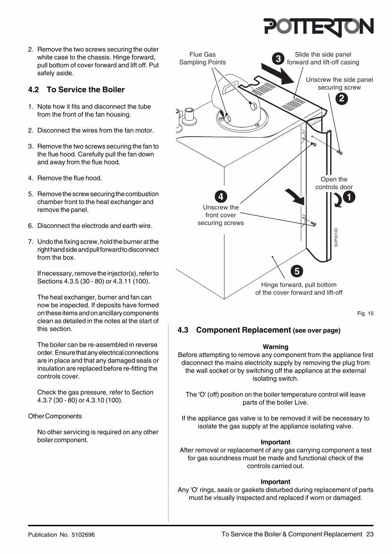
Fig. 15
2. Remove the two screws securing the outerwhite case to the chassis. Hinge forward,pull bottom of cover forward and lift off. Putsafely aside.
4.2 To Service the Boiler
1. Note how it fits and disconnect the tubefrom the front of the fan housing.
2. Disconnect the wires from the fan motor.
3. Remove the two screws securing the fan tothe flue hood. Carefully pull the fan downand away from the flue hood.
4. Remove the flue hood.
5. Remove the screw securing the combustionchamber front to the heat exchanger andremove the panel.
6. Disconnect the electrode and earth wire.
7. Undo the fixing screw, hold the burner at theright hand side and pull forward to disconnectfrom the box.
If necessary, remove the injector(s), refer toSections 4.3.5 (30 - 80) or 4.3.11 (100).
The heat exchanger, burner and fan cannow be inspected. If deposits have formedon these items and on ancillary componentsclean as detailed in the notes at the start ofthis section.
The boiler can be re-assembled in reverseorder. Ensure that any electrical connectionsare in place and that any damaged seals orinsulation are replaced before re-fitting thecontrols cover.
Check the gas pressure, refer to Section4.3.7 (30 - 80) or 4.3.10 (100).
Other Components
No other servicing is required on any otherboiler component.
4.3 Component Replacement (see over page)
WarningBefore attempting to remove any component from the appliance firstdisconnect the mains electricity supply by removing the plug from
the wall socket or by switching off the appliance at the externalisolating switch.
The 'O' (off) position on the boiler temperature control will leaveparts of the boiler Live.
If the appliance gas valve is to be removed it will be necessary toisolate the gas supply at the appliance isolating valve.
ImportantAfter removal or replacement of any gas carrying component a test
for gas soundness must be made and functional check of thecontrols carried out.
ImportantAny 'O' rings, seals or gaskets disturbed during replacement of parts
must be visually inspected and replaced if worn or damaged.
1
2
3
4
5
SU
P00
13C
Slide the side panelforward and lift-off casing
Flue GasSampling Points
Unscrew the side panelsecuring screw
Unscrew thefront cover
securing screws
Open thecontrols door
Hinge forward, pull bottomof the cover forward and lift-off
Publication No. 510269624
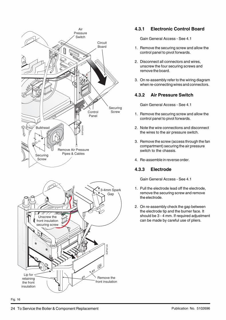
4.3.1 Electronic Control Board
Gain General Access - See 4.1
1. Remove the securing screw and allow thecontrol panel to pivot forwards.
2. Disconnect all connectors and wires,unscrew the four securing screws andremove the board.
3. On re-assembly refer to the wiring diagramwhen re-connecting wires and connectors.
4.3.2 Air Pressure Switch
Gain General Access - See 4.1
1. Remove the securing screw and allow thecontrol panel to pivot forwards.
2. Note the wire connections and disconnectthe wires to the air pressure switch.
3. Remove the screw (access through the fancompartment) securing the air pressureswitch to the chassis.
4. Re-assemble in reverse order.
4.3.3 Electrode
Gain General Access - See 4.1
1. Pull the electrode lead off the electrode,remove the securing screw and removethe electrode.
2. On re-assembly check the gap betweenthe electrode tip and the burner face. Itshould be 3 - 4 mm. If required adjustmentcan be made by careful use of pliers.
To Service the Boiler & Component Replacement
Fig. 16

Publication No. 5102696 25To Service the Boiler & Component Replacement
Fig. 17
4.3.4 Burner 30 - 80 models
Gain General Access - See 4.1
1. Disconnect the electrode lead and earthwire.
2. Undo the fixing screw, hold the burner atthe right hand side and pull forwards todisconnect from the air box.
3. Unscrew the electrode and transfer to thenew burner.
4. Re-assemble in reverse order, on re-assembly hook the rear of the locatingbracket (1) in place before locating the front(2).
4.3.5 Injector 30 - 80 models
Gain General Access - See 4.1
1. Remove the burner - See 4.3.4.
2. Use a 13mm (A/F) or ½" (A/F) socketspanner to remove the injector.
3. Unscrew the injector, use a new sealingwasher on re-assembly.
If using a flat spanner to remove the injectorsee the next section (4.3.6.)
4.3.6 Combustion ChamberInsulation 30 - 80 models
Gain General Access - See 4.1
1. The front insulation is accessible as thefront is already off.
2. Remove the burner - See 4.3.4.
3. Remove the two screws securing the sideand rear insulation assembly to the front ofthe chassis.
4. Pull the assembly forwards and away fromthe boiler. Replace insulation pieces asrequired, replace any securing clip ifdamaged.
5. Re-assemble in reverse order.

Publication No. 510269626
4.3.7 Gas Valve 30 - 80 models
Gain General Access - See 4.1
1. Pull off the electrical connector at the valve.
2. Remove the gas cock by unscrewing thefour long hexagonal head screws from thebase of the valve.
3. Remove the burner - See 4.3.4.
4. Remove the screw securing the controlsassembly to the top of the valve.
5. Remove the two screws securing the sideand rear insulation assembly to the front ofthe chassis and remove assembly.
6. Remove the three screws securing the gasvalve manifold assembly to the chassis andremove the complete assembly.
7. Remove the three M5 x 16mm screwssecuring the gas manifold to the gas valve.
8. Use a new 'O' ring and refit the manifold tothe new gas valve.
9. Re-assemble in reverse order, use a newside panel gasket and 'O' ring in the gascock.
10. Check that the burner pressure is inaccordance with the information on theboiler data badge. If adjustment is required,turn the pressure adjusting screw anti -clockwise to increase pressure or clockwiseto decrease.
To Service the Boiler & Component Replacement
Fig. 18
Gas Pressureadjuster

Publication No. 5102696 27
4.3.8 Burner 100 model
Gain General Access - See 4.1
1. Disconnect the electrode lead and earthwire.
2. Undo the fixing screw, hold the burner atthe right hand side. Pull forwards and tothe left, disconnect from the air box andsupport tab.
3. Unscrew the electrode and transfer to thenew burner.
4. Re-assemble in reverse order.Locate the left hand side of the burner ontothe support tab on the side insulation. Hookthe rear of the locating bracket (2) in placebefore locating the front (3) and re-fitting thescrew.
4.3.9 Combustion ChamberInsulation 100 model
Gain General Access - See 4.1
1. The front insulation is accessible as thefront is already off.
2. Remove the burner - See 4.3.8.
3. Remove the two screws securing the sideand rear insulation assembly to the front ofthe chassis.
4. Pull the assembly forwards and away fromthe boiler. Replace insulation pieces asrequired, replace any securing clip ifdamaged.
5. Re-assemble in reverse order.
To Service the Boiler & Component Replacement
Fig. 19

Publication No. 510269628
Gas Pressureadjuster
To Service the Boiler & Component Replacement
Fig. 20
4.3.10 Gas Valve 100 model
Gain General Access - See 4.1
1. Turn gas cock OFF, see ig.20.Pull off the electrical connector at the valve.
2. Remove the gas cock by unscrewing the four longhexagonal head screws from the top of the valve.
3. Remove the burner - See 4.3.8.
4. Remove the two screws securing the side and rearinsulation assembly to the front of the chassis andremove assembly.
5. Remove the three screws securing the gas valvemanifold assembly to the chassis and remove thecomplete assembly.
6. Remove the four screws securing the gas manifoldto the gas valve.
7. Use a new 'O' ring and refit the manifold to the newgas valve.
8. Re-assemble in reverse order, use a new 'O' ring inthe gas cock and a new injector manifold gasket.
9. Check that the burner pressure is in accordance withthe information on the boiler data badge. If adjustmentis required, turn the pressure adjusting screw anti -clockwise to increase pressure or clockwise todecrease.

Publication No. 5102696 29To Service the Boiler & Component Replacement
Fig. 21
4.3.11 Injectors 100 model
Gain General Access - See 4.1
1. Remove the burner - See 4.3.8.
2. Use a 13mm (A/F) or ½" (A/F) socketspanner to remove the injectors.
3. Unscrew the injector, use a new sealingwasher on re-assembly.
4.3.12 Fan & Flue Hood
Gain General Access - See 4.1
1. Disconnect the tube from the front of thefan housing - note how it fits.
2. Disconnect the wires from the fan motor.100 model only, loosen the baffle platesecuring screw and remove the baffle plate.
3. Remove the three screws securing the fanto the flue hood.
4. Carefully pull the fan away from the boiler.
5. Flue Hood: On re-assembly ensure thatthe flue hood locates under the two bracketsat the rear of the chassis. Check the sealand replace if damaged.
6. Fan: On re-assembly ensure that the rubberseal around the fan opening is locatedcorrectly into the base of the flue elbow.
7. Re-assemble in reverse order.

Publication No. 510269630
4.3.13 Temperature Sensor
Gain General Access - See 4.1
1. Disconnect the wires from the sensor.
2. Depress the clips on the outside of thesensor and pull it clear of the pipe.
3. Re-assemble in reverse order, use freshconducting paste.
4.3.14 Overheat Thermostat
Gain General Access - See 4.1
1. Disconnect the wires from the thermostat.
2. Unscrew the thermostat.
3. Re-assemble in reverse order.
To Service the Boiler & Component Replacement
Fig. 22
Publication No. 5102696 31
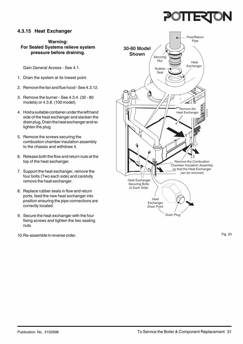
4.3.15 Heat Exchanger
Warning:For Sealed Systems relieve system
pressure before draining.
Gain General Access - See 4.1.
1. Drain the system at its lowest point.
2. Remove the fan and flue hood - See 4.3.12.
3. Remove the burner - See 4.3.4. (30 - 80models) or 4.3.8. (100 model).
4. Hold a suitable container under the left handside of the heat exchanger and slacken thedrain plug. Drain the heat exchanger and re-tighten the plug.
5. Remove the screws securing thecombustion chamber insulation assemblyto the chassis and withdraw it.
6. Release both the flow and return nuts at thetop of the heat exchanger.
7. Support the heat exchanger, remove thefour bolts (Two each side) and carefullyremove the heat exchanger.
8. Replace rubber seals in flow and returnports, feed the new heat exchanger intoposition ensuring the pipe connections arecorrectly located.
9. Secure the heat exchanger with the fourfixing screws and tighten the two sealingnuts.
10.Re-assemble in reverse order.
To Service the Boiler & Component Replacement
Fig. 23
SU
P02
19B
Drain Plug

Publication No. 510269632
5. Functional Wiring Diagram
Functional Wiring Diagram
Boiler Lighting Sequence1. Supply external voltage to boiler terminal connections
L and N, 230 volts, 50 HZ.2. Supply external voltage to boiler terminal connection,
switch line SW 230 volts, 50 HZ.3. Pump live from boiler energised, diverter/zone valves
operate in accordance with system demand.4. Boiler control checks, air pressure switch for "No Air
Condition" (red light "On", green light "Flashing").5. If "No Air" the control switches on the fan.6. After ten seconds air pressure switch proves fan is on.7. Gas valves open and ignition for 3 seconds (green
light flashes rapidly).8. Boiler firing (green light "On" only).9. If the flame is not detected at this time, the boiler will
turn off.
10.The above sequence will repeat for a further twoignition attempts before going to lockout (indicated bythe red light flashing).
11.Pressing the reset button will re-start boiler at No. 1.12.The control will continue to run the pump for several
minutes after any firing of the boiler.13.The control will run the pump automatically for a few
minutes every twenty four hours to maintain the freerunning of the pump.
14.The standby position on the thermostat control knobwill prevent the boiler firing but will permit operation ofthe pump for sequences 12 and 13.
Fig. 24

Publication No. 5102696 33Wiring Diagram
6. Wiring Diagram
Fig. 25
Publication No. 510269634
7. Fault Finding Guide
Fault Finding
Sequence of Events
1. On start-up boiler checks thata. The reset button is not stuck ONb. The Live and Neutral are not swappedc. There is no Pump Live wiring faultd. The gas valve is not energisede. There is no flame detected
Note: If there is a fault the Control will go to lockout
2. Control continues to hold gas valve open until either the set temperature is reached or the switch live demand isremoved
3. Pump remains energised whilst there is a demand
4. Setting control thermostat to 'O' has the same result as reaching the set temperature
5. Control checks that flame is not detected
6. Control re-starts ignition sequence
Check list in the event of a fault
1. Switched Live call for heat is recognised by the Control but as boiler control thermostat is set to 'O' the ignitionsequence is not started
2. Flashing Green indicates a call for heat to the user
3. Control thermostat set to call for heat
4. Control starts ignition sequence, Air Pressure Switch is checked for open circuit
5. Fan is energised
6. If APS fails to operate control goes to Blocking error (Red light flashes but no need to press reset). Control waitsfor APS to operate before energising gas valve and starting EHT spark
7. Control checks gas valve is energised. If valve is not energised overheat thermostat may be faulty
8. Control checks for flame detection within 3 seconds, if a flame is not detected the fan is turned off and the ignitionsequence is restarted for two further attempts from '4'
Intermittent Lockout - Main causes are: Switch Live connected to Pump LivePoor burner ignition due to gas pressurePoor burner ignition due to incorrect spark gapSlow opening gas valve after a long standby periodWeak spark due to electrode lead or ControlPre-pay gas meter running out
Other common reasons for complaint are: Other system faults (actuator, room thermostat, timer)Lack of user education in the operation of system controlSystem wiring faults affecting operation or temperature

Publication No. 5102696 35Fault Finding

Publication No. 510269636
8. Short List Of Spare Parts
Short List Spare Parts
Fig. 26

Publication No. 5102696 37Short List Spare Parts
G.C. No.
114 982114 860114 861114 863173 132173 154114 832114 833114 962114 963114 945114 954114 864
173 155
173 130173 133173 134173 135173 137173 138173 139337 862114 873114 874114 875114 948114 949114 776114 810114 811114 983114 858114 859
Description
ElectrodeEarth Lead 30 - 80 modelsEarth Lead 100 modelTemperature ControlGas Valve 30 - 80 modelsGas Valve 100 model (soft light)Manifold Gasket - Case/Manifold 30 - 80 modelsInjector/Manifold Gasket - Case/Manifold 100 modelManifold 'O' Rings - Gas Cock (Qty 2 off on 100 model)
- ManifoldFlue Elbow SealCircuit BoardThermostat KnobPressure Switch 30, 60, 70 & 100 models
40 model50 model80 model
Fan Assembly 30 to 40 models50 model60 to 70 models80 model100 model
Overheat ThermostatInjector - Main Burner 30
405060 & 7080100
Flue ScraperFront Panel Seal - Type 1Front Panel Seal - Type 2Front Panel Seal - Type 3Fan Outlet SealFlue Tube/Elbow SealTemperature SensorFan Gasket - 30 to 50
- 60 to 100Fuse (Type: 3.15AT)Electrode Lead 30 - 80 modelsElectrode Lead 100 model
Part No.
84077548238268823826989330124025504025528238225838822684016488401656823814684077508238172510557451055755105576510586751059005105868510590151055735105902840451784110218411022841102384110258411026841102890773686506918650692865069382381478238148840451682381638238165816003884077538407756
Qty.
11111111111111111111111111112112111111111
Drg. Ref.
12
34
5
67891011
12
1314
151616a16b17181920
2122

Publication No. 510269638
Flue Kits
Optional Extras - Flues
Fig. 27
■■■■■
■ ■ ■ ■ ■ Check availability of these kits before ordering

Publication No. 5102696 39
Installation instructions included as necessary with each kit.
1m Flue Extension KitSales Code: ULT2EXTN(Not 100 models)
(Max. 3 Kit)
A) Extension Air Tube (Outer)
B) Extension Flue Tube (Inner)
C) Self Tapping Screws (6 off)
A) Flue LinerB) Rubber SealC) Screws & PlugsD) RopeE) Retaining Collars
Flat RoofFlashing KitSales Code:PUMAKITK
90˚ In-Line Bend KitSales Code:PUMAKITB(Not 100 models)
135˚ In-Line Bend KitSales Code:PUMAKITC(Not 100 models)
A) 90˚ or 135˚ In-Line ElbowB) Product Tube 'O' Ring (2 off)C) Air Tube Clamp (Including Nuts & Screws)D) Air Tube Seal (2 off)
D) Fixing Bracket
E) Woodscrews (2 off)
F) Wall Plugs (2 off)
A
ED
FB
Wall Plate PackSales Code:SUPKITB
Concentric VerticalFlue Adaptor KitSales Code:SUPKITC
(Not 100 models)
BD
C
A
D
A E E
B
CTelescopic In-LineBend AdaptorSales Code:SUPKITR(Not 100 models)
Terminal GuardSales Code:PTERMGUARDEF
Internal Fitment KitSales Code:SUPKITA
C
B
A
A
Pitched RoofFlashing KitSales Code:PUMAKITL
SU
P00
38D
Min. Offset Flue KitSales Code: 3SUPKIT
A) Terminal Elbow
B) Terminal Adaptor
C) Terminal Assem.
D) Drip Ring
E) Sealing Tape
F) Screw Pack
G) Wall Template
F
E
AB
C
D
Twin Tube 90˚In-Line Bend KitSales Code:PUMAKITI(Not 100 models)A) 2 off- 90˚ In-Line Bend
Twin Tube135˚In-Line Bend KitSales Code:PUMAKITJ(Not 100 models)A) 4 off-135˚ In-Line Bend
A
1m Twin Tube FlueExtension KitSales Code:PUMAKITH(Not 100 models)A) Extension Tubes (2 off)
B) Fixing Brackets (2 off)
G
Optional Extras - Flues
Fig. 28
■ ■ ■ ■ ■ Check availability of these kits before ordering
■■■■■ ■■■■■
■■■■■
■■■■■ ■■■■■
■■■■■
Publication No. 510269640
System and Other Kits
COM
P AC
T
DHW
PORT BC
H
PORT A
MA
NU
AL O
VERR
IDE O
NLY
AUTOM
ID
5
6
3
2bar
1
4
Fixing Pack
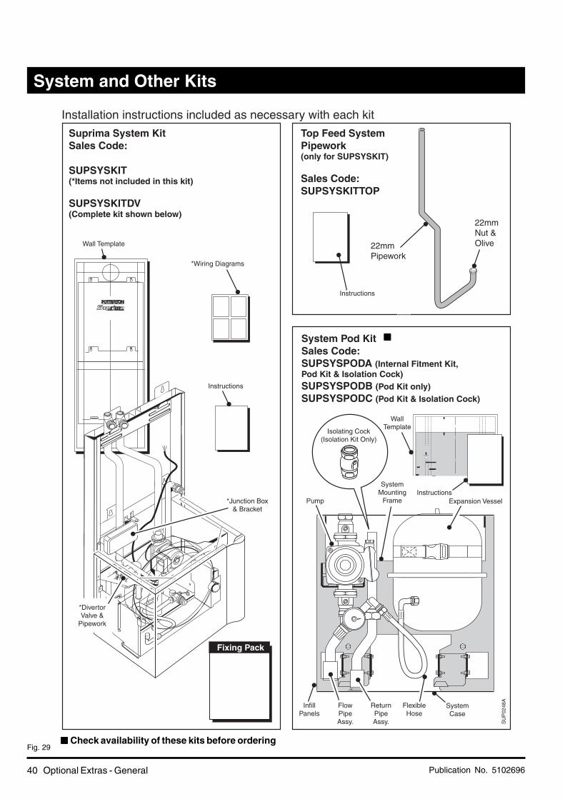
Wall Template
*Wiring Diagrams
Suprima System KitSales Code:
SUPSYSKIT(*Items not included in this kit)
SUPSYSKITDV(Complete kit shown below)
Installation instructions included as necessary with each kit
Top Feed SystemPipework(only for SUPSYSKIT)
Sales Code:SUPSYSKITTOP
System Pod KitSales Code:SUPSYSPODA (Internal Fitment Kit,Pod Kit & Isolation Cock)SUPSYSPODB (Pod Kit only)SUPSYSPODC (Pod Kit & Isolation Cock)
Instructions
*Junction Box& Bracket
*DivertorValve &
Pipework
22mmPipework
22mmNut &Olive
WallTemplate
Expansion VesselInstructions
SystemCase
Instructions
FlexibleHose
SU
P02
48A
ReturnPipeAss.
FlowPipeAssy.
ReturnPipeAssy.
Pump
InfillPanels
Isolating Cock(Isolation Kit Only)
SystemMounting
Frame
Optional Extras - General
Fig. 29■ ■ ■ ■ ■ Check availability of these kits before ordering
■■■■■
Publication No. 5102696 41
SU
P00
40E
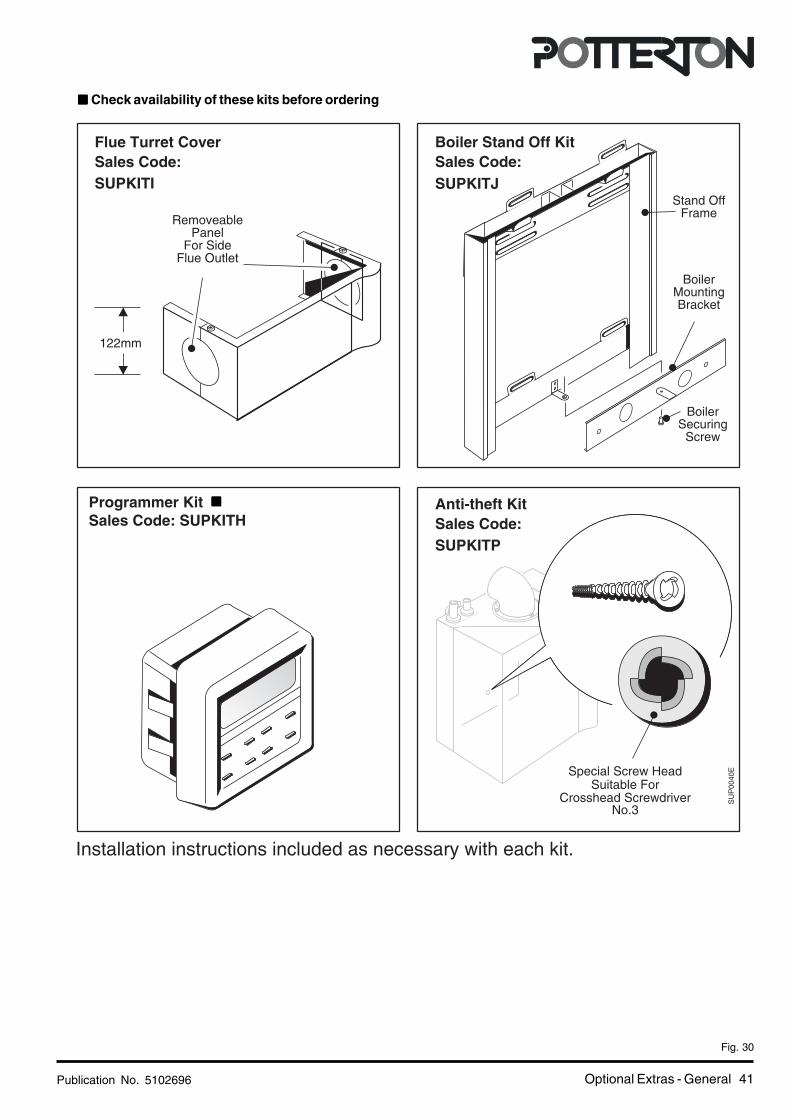
Flue Turret CoverSales Code:SUPKITI
Anti-theft KitSales Code:SUPKITP
Special Screw HeadSuitable For
Crosshead ScrewdriverNo.3
F
R
Installation instructions included as necessary with each kit.
BoilerMountingBracket
Stand OffFrame
BoilerSecuring
Screw
122mm
RemoveablePanel
For SideFlue Outlet
Boiler Stand Off KitSales Code:SUPKITJ
Programmer KitSales Code: SUPKITH
Optional Extras - General
Fig. 30
■ ■ ■ ■ ■ Check availability of these kits before ordering
■■■■■

Publication No. 510269642
Intentional Blank
Intentional Blank

Publication No. 5102696 43
Intentional Blank
Intentional Blank

Baxi PottertonBrownedge Road, Bamber Bridge
Preston, LancashirePR5 6SN
www.potterton.co.uk
All descriptions and illustrations provided in this leaflet have been care-
fully prepared but we reserve the right to make changes and improve-
ments in our products which may affect the accuracy of the information
contained in this leaflet. All goods are sold subject to our standard
Conditions of Sale which are available on request.
* To aid continuous improvement and staff training, calls to this
line may be monitored or recorded.
���������������
���� �������������
����������
���� �������������
���������
���� �������������
���� ������������
���������������
���� �����������
Publication No. 5102696 - Iss. 02 (12/2001)

User's Guide Suprima30L - 120Land System L
About the Boiler This is a Wall Mounted Fan Assisted Balanced Flue Gas Boiler.This boiler is for use with Natural Gas (G20) only at 20mbar and for use in GB & IE.Your boiler is fully automatic in operation and requires very little attention apart from setting thethermostat.
About Safety • The Gas Safety (Installation and Use) Regulations 1998.
• This Appliance Must be installed and serviced by a Competent Person as stated in the aboveRegulations.
• If it is known or suspected that a fault exists on the appliance, it must not be used until the fault hasbeen corrected by a competent person.
• If the appliance is installed in a compartment, do not use it for storage purposes. Do not obstruct anypurpose provided ventilation openings.
• If a gas leak or fault is suspected turn off the appliance and consult your Local Gas Region or ServiceEngineer.
• Any warning labels on the appliance must be adhered to.
• Consumer Notice: Please make sure you have carried out the simple checks detailed in theseinstructions before asking for a Service Engineer to call, as a charge will be made for a service callif it is not due to a manufacturing fault on the appliance.
• The appliance should have the following minimum clearances for Safety and Maintenance, 15 mm at thefront (610 mm for servicing access), 5 mm each side, 50 mm at the bottom and 125 mm above the case.Flammable materials must not be stored in close proximity to the boiler. Ensure that the flue terminal,outside the house, does not become obstructed, particularly by foliage.
• Potterton is a member of the Benchmark initiative and fully supports the aims of the programme.Benchmark has been introduced to improve the standards of installation and commissioning of centralheating systems in the UK and to encourage the regular servicing of all central heating systems to ensuresafety and efficiency.
The Benchmark Log Book is an important document andmust be kept safely with the boiler. Failure to install andmaintain this appliance in accordance with themanufacturer’s instructions may invalidate the warranty.
You should ensure that your installer/service engineercompletes the relevant sections of the log book whenappropriate.
• Samples of the Suprima boilers have been examined byGastec, a United Kingdom Notified Body. The range is certifiedto comply with the essential requirements of the Gas ApplianceDirective 90/396/EEC, the Low Voltage Directive 72/23/EECand shows compliance with the Electro Magnetic CompatibilityDirective 89/336/EEC, the Boiler Efficiency Directive 92/42/EEC and are therefore permitted to carry the CE Mark.
TM

Publication No. 51028712 User's Guide
BoilerCodeNumber
BarCode
Model
GC. No.
DataBadge
ControlsCover
SU
P02
81A
ResetButton
L.E.D.(Green)
L.E.D.(Red)
TemperatureControl('0' Standby)
OptionalProgrammer
Temperature
Reset
M a x0
POTTERTON G.C. No. 41 590 42
9016
BOILER CODE No. ALVG101 0003SUPRIMA 30 L
To Light
Note: When the boiler is first operated, there may be a slightsmell. This will disappear with use.
1. Ensure that the boiler thermostat knob is set at 'O' (fullyanti-clockwise).
2. Switch ON the main electricity supply, the upper RedL.E.D. should be on.
3. Ensure the electronic programmer or other time control,if fitted, is in an 'ON' position (refer to the time controlliterature).
4. Ensure that any room and/or cylinder thermostats are ata high temperature setting.
5. Turn the boiler thermostat 'ON' and to the required settingand the lower Green L.E.D. will start to flash. After a shortperiod, the lower Green L.E.D. will flash rapidly and thenbecome constant as the boiler lights up. When the boilerreaches the temperature setting on the boiler thermostat,the boiler will switch off, the Red L.E.D. will come on andthe Green L.E.D. will flash.
6. Set the time control and any thermostats to their desiredsettings.
Reset Button
If the boiler fails to light after three attempts it will lockout andthe Red L.E.D. will start to flash. Press the reset button (DoNot use excessive pressure), the Red L.E.D. will stop flashingand the boiler will attempt to relight a further three times.If the boiler will not light, then you should call your installeror maintenance contractor.
To Shut Off - Short Periods
Turn the boiler thermostat knob to 'O' (Standby) or switch theprogrammer to the 'OFF' position. To operate the boiler,simply turn the boiler thermostat to the required setting andswitch the programmer 'ON'.
To Shut Off - Long Periods
Turn the boiler thermostat knob to 'O' (Standby), isolate theelectrical supply at the isolating switch, or pull the electricalplug out of the wall socket.Important: Read the section on Frost Precaution.
Temperature Control
This enables you to control the temperature of the water asit leaves the boiler and is also used for turning the boiler onand off. The control can be set between 'O' (Standby) andMax which corresponds approximately to a temperaturerange of 55 °C to 82 °C
During the summer months, when the boiler is only beingused to supply stored domestic hot water and there is noindependent hot water temperature control, the thermostatcan be set to a low setting which will probably be hot enoughfor bathing or washing up requirements. For washing clothesa higher setting may be necessary.
In winter weather, when central heating is required, thethermostat knob can be turned up higher but it must beremembered that unless the temperature of the water in thedomestic hot water cylinder is independently controlled, thestored hot water could be at a temperature that could scald.
SEDBUK Declaration for Suprima
Model Seasonal Efficiency(SEDBUK) (%)
30L 78.040L 78.550L 78.160L 78.170L 78.780L 78.8100L 78.0120L 78.7
This value is used in the UKGovernment's Standard AssessmentProcedure (SAP) for energy rating ofdwellings. The test data from which ithas been calculated have been certifiedby 0063.
Warning
Do not interfere with any sealed componentson this appliance
It is important that the case of this appliance is notremoved for any reason other than for servicing
by a qualified service engineer.
The appliance must not be operated without thecasing correctly fitted and forming an adequate seal.
Avoid skin contact when the boiler is in operation, assome surfaces may get hot i.e. sight glass, pipework.

Publication No. 5102871 3User's Guide
Pump Overrun
The boiler controls operate the pump for several minutesafter the shut down of the boiler to prevent overheating. Theboiler controls will also operate the pump for a few minutesevery 24hrs, to maintain the free running of the pump.
Other Controls
A Potterton Electronic Programmer or other type of clockmay have been fitted in your system, together with roomand/or cylinder thermostats. Full instructions on the use ofthese controls should be supplied with them.
Important
Gas and electricity are required to operate your boiler. Itsperformance will not be affected by normal variation ineither supply, but a gas or electricity failure will put the boilerout of operation. It will automatically re-start when thesupply is restored provided that the time clock and/orthermostats are in the 'On' position.
Note: If the boiler is running and the gas is turned Off, theboiler will switch off and attempt to light twice, after which theRed L.E.D. will flash. The Reset Button will have to bepressed before the boiler will relight.
Overheat Limit Thermostat
The boiler is fitted with a safety thermostat to protect againstoverheating of the water. If this thermostat operates theboiler will lockout and the Red L.E.D. will start to flash. Pressthe reset button (Do Not use excessive pressure), the RedL.E.D. will stop flashing and the boiler will attempt to re-light.If the control does not reset, leave the boiler for approx. 15minutes before pressing the reset button again.
If the problem persists, turn off the boiler and consult yourLocal Installer or Service Engineer. Note: Interruption of theelectrical supply to the boiler may also cause the overheatthermostat to operate.
LED Indicators - Normal Modes
Status Green LED Red LED
Mains ON Only OFF ON
Ext. Call for Heat FLASHING ON(Boiler set to STNDBY, 2 Per Sec.Temp. Control set to 'O' Off)
Ext. Call for Heat FLASHING OFF(STNDBY switch to ON, 2 Per Sec.Temp. Control set to Max.)
Ignition FLASHING OFF(i.e. Gas and Sparks ON) 16 Per Sec.
FLAME Detected ON OFF
Boiler Temperature FLASHING ONControl Satisfied 2 Per Sec.
Lockout OFF FLASHING2 Per Sec.
Having checked these points, run through the lightingprocedure once more and if the boiler still fails to light, callin your Service Engineer.
Frost Precautions
If your boiler has to be shut down for several hours or moreduring very cold weather, it may be in danger of freezing,due to its position, i.e. it may be in an outhouse or part of thepipework may be vulnerable to frost. To avoid freezing,various methods of protection can be used:-
1. Insulation of the boiler and pipework, taking care not toimpede any ventilation or air supply.
2. Completely draining the water system if not in use forlong periods. On a sealed system, draining and refillingmust be carried out by a competent person.
Note: Although the system can be emptied by using thedrain off taps installed in the pipework around the system,to empty the boiler, it is necessary to remove the drainscrew which is situated on the heat exchanger casting.This should only be done by a competent person.
3. Have a low limit thermostat fitted. If the system is fittedwith a low limit thermostat and protection of the systemis required during cold weather, all that is required is forthe programmer to be turned to the 'Off' position. This willallow the boiler to operate if the temperature within thehouse becomes too low. The low limit thermostat will notoperate if the boiler is completely shut down and theelectricity supply turned off. In this instance, the systemwill have no protection and one of the other methodsmust be used.
4. Where no frost protection is provided it may be necessaryto run the boiler at low thermostat settings at all timeswhen it would normally be shut off.
Cleaning the Outside of the Boiler Casing
The outside of the boiler casing can be wiped whennecessary by using a damp cloth to remove finger marksetc. Do not use an abrasive cleaner as this may damage thecasing finish.
Information for the Suprima System Boiler
The system water pressure should be checked periodically.This is done by removing the lower cover, released bypulling forward at the base, to expose the pressure gauge.The gauge is situated on the right hand side of the pump. Ifthe needle falls below the point indicated by the red marker,this shows water is leaking from the system and that it needsre-charging. Your installer can advise you on what to do withyour particularsystem. Re-fitthe cover intothe spring clipsafter checking.

Care Of Your Boiler and System During the GuaranteePeriod and Beyond:
1. Registration of Purchase
It is important to register the purchase of your Potterton boiler toensure you receive prompt and efficient handling in the eventyour boiler requires attention during the guarantee period.
To register your guarantee simply complete and detach theRegistration of Purchase form enclosed with these instructions.It is important to include details of your installer (if known) and toreturn the completed form to the Potterton RegistrationDepartment.
2. During the Guarantee Period
In the event of any problems with your system or the operation ofthe boiler, you should first call your installer. If there is a faultwith the boiler under guarantee which your installer is unable torectify, he/she will call Potterton Service Operations. For 12months from the date of installation (or 18 months from the dateof manufacture, which ever is shorter), Potterton will attend to anymanufacturing defect, on the appliance only (not the system orancillary controls), free of charge for parts and labour, subject tothere being no misuse or abuse. This does not effect yourstatutory rights.
Service visits by Potterton Service Operations outside the termsof the boiler guarantee, will be charged for both parts and labourat our normal rates for chargeable work. During the period of theboiler guarantee, Potterton will only be responsible for the cost ofwork done by them or on their instructions by their Agent. Wecannot accept any liability for expenditure or work done by otherparties without our knowledge and/or approval.
3. Safety Check / Routine MaintenanceIt is strongly recommended you have your boiler checked annuallyfor safety and for routine maintenance. This should be carried outby a CORGI Registered Installer/Service Agent or PottertonService Operations to comply with the requirements of the GasSafety (Installation & Use) Regulations 1998.
4. Boiler Breakdown Insurance
We are pleased to offer you the opportunity to protect yourinvestment once your initial boiler guarantee has expired, by thepayment of an annual premium. You can continue with thisinsurance for the normal life of your boiler and you will find aspecial 30 day introductory offer for a second year cover togetherwith a card to register your purchase, as part of the “User Pack”supplied with your boiler.
If you have not been handed a Registration Card/additional2nd Year Breakdown Insurance offer, Please contact thePotterton Registration Department for a copy by telephoning(020) 8944 4972.
Baxi PottertonBrownedge Road, Bamber Bridge
Preston, LancashirePR5 6SN
www.potterton.co.uk
All descriptions and illustrations provided in this leaflet have been
carefully prepared but we reserve the right to make changes and
improvements in our products which may affect the accuracy of the
information contained in this leaflet. All goods are sold subject to our
standard Conditions of Sale which are available on request.
* To aid continuous improvement and staff training, calls to
this line may be monitored or recorded.
General Enquiries
Tel. 08706 060 780Technical *
Tel. 08706 049 049Service *
Tel. 08706 096 096Fax. 01926 410 006
Literature Request
Tel. 08706 060 623
Publication No. 5102871 - Iss. 02 (02/2002)