powder spraygun - a r berry & coarberryco.com.au/wagner/pem-c2.pdf · operating manual powder...
TRANSCRIPT

Operating Manual
Powder Spraygun
DANGER
High Voltage! Turn power off
before servicing!
CAUTIONRead rules for safe
operation and instructions carefully!
PEM-C2
02/01 0351801

PEM-C2
Powder Spraygun PEM-C2 Part No. 0351 021
AB
D
HC
EG
F
A Electrode B Deflector cone C Outer nut D Spraygun body
E Trigger F Atomizing air supply G Powder supply H Power supply
The powder spraygun PEM-C2 is used for industrial powder coating. This spraygun can be operated with the following control units:
• EPG 2007 with powder injector PJ 2020 PRS
• EPG Digiflow with powder injector PJ-D1
The high voltage in the spraygun is activated by pressing the trigger. At the same time, the powder and compressed air supplies to the gun are turned on.
Caution
The user must ensure, that the spraygun is only connected to Wagner equipment! High ambient temperatures must be avoided; in particular, the hoses must not be routed through factory areas exposed to direct sunlight! To provide a safeguard against unintentional use of the spraygun, the control unit must be turned off! Powders containing metal pigments may only be processed in compliance with the powder manufacturer’s instructions.
02/01 2 0351801

PEM-C2
Table of contents Page
1. Introduction .................................................................................................................5 1.1 Safety regulations..........................................................................................................6 1.2 General safety rules ......................................................................................................6 1.3 Harmless discharge.......................................................................................................8 2. Preparing the spraygun for your application ...........................................................9 2.1 Select the suitable nozzle system .................................................................................9 2.2 Connecting the spraygun ............................................................................................10 2.3 Grounding....................................................................................................................10 2.4 Corona-Star.................................................................................................................11
3. Working with the spraygun ......................................................................................12 3.1 Starting up the spraygun .............................................................................................12 3.2 How to switch off the spraygun ...................................................................................13 3.3 How to carry out a change of color..............................................................................14 4. Maintenance and cleaning........................................................................................15 4.1 Replacing the spraygun...............................................................................................15 4.2 Cleaning the spraygun and replace the wear parts.....................................................16 5. Mounting the extension ............................................................................................17 6. Trouble shooting .......................................................................................................18 7. Spare parts lists ........................................................................................................19 7.1 How to order................................................................................................................19 7.2 Spraygun PEM-C2 ......................................................................................................19 7.3 Round spray nozzle, extension ...................................................................................20 7.4 Corona-Star Retrofit-Set..............................................................................................20 8. Specification ..............................................................................................................21 9. Supplement................................................................................................................22 9.1 Applicable safety regulations and list of sources.........................................................22 9.2 Warranty......................................................................................................................23
02/01 3 0351801

PEM-C2
02/01 4 0351801

PEM-C2
1. Introduction This technical manual contains information and hints for the service, repair and maintenance of the equipment. The observation of this manual is element of the warranty agreements. Wagner powder systems are designed to meet the most stringent safety requirements. They can be operated in compliance with generally applicable safety codes and applicable national safety regulations. Please pay particular attention to the parts marked by the following symbols. Follow the instructions exactly, in the interests of both your own safety and the correct functioning of the unit.
Warning
This warning draws attention to the fact that if the operating instructions, working instructions, prescribed working sequences etc. are not followed exactly, this can lead to injury or even fatal accidents.
Caution
This warning indicates that if the operating instructions, working instructions, prescribed working sequences etc. are not followed exactly, this can lead to damage to the unit.
Hint
This symbol draws your attention to useful additional information and tips.
Wagner hereby declares that the unit described in these operating instructions has been designed and manufactured according to the provisions of EU Directive 98/37/EC.
The following harmonized standards have been applied: EN 50014 EN 50053 EN 50050 EN 1953 The following German standards or guidelines have been applied: ZH 1/443 VDE 0165 VDMA 24371 part 1 The certificate of conformity with the order No. 0351 932 is enclosed with this product. This can be reordered from your WAGNER representative giving the product and serial number.
02/01 5 0351801

PEM-C2
1.1 Safety regulations
Warning
This equipment can be dangerous if it is not operated in accordance with this operating manual! There might be additional regulations to be observed, put into effect by governmental, state or other official agencies or local security (fire) departments!
The following rules must be observed in order to ensure a safe and efficient use of the equipment: • Under no circumstance may persons with a cardiac
pacemaker come close to the area between the tip of the spraygun and the workpiece to be coated!
• The user has to observe particularly the safety guidelines of the VdS or the local professional and security institutions. 2) 3) 6) 9)
• The spraygun may only be operated in the hazard zone created by operation of the manual spraying equipment itself. 2) 3) 6)
• The spraygun may only be operated in powder spray booths or powder spray benches equipped with industrial ventilation. 2) 3) 6
• The user has to ensure that the medium value of the powder/air concentration does not exceed 50% of the LEL (maximum allowed concentration of powder in air). If the LEL is not known, the user should assume a value of 20 g/m³. 2) 3) 6)
• The main power connection for operation of the Wagner powder equipment must be electrically interlocked with the exhaust system of the powder coating booth. 2) 3) 6)
• The Wagner control unit must be installed outside the hazard area. 2) 3)
• The user must conduct periodic checks of the powder
spray equipment (at least every year) with regard to explosion-protection. 5) 7)
• In the event of faults or defects, repair work is to be performed at the user's discretion. 7)
• The user must keep a test certificate of the device type on file at the installation site. 7)
• The execution of repairs must not lead to an alteration in the explosion-protection. 5) 7)
• Repairs may only be carried out by specially trained personnel. 7)
• Repairs must never be performed in an explosion-hazard area. 7)
• The work area must have an electrostatically conductive floor (measured in accordance with DIN 51953) 2) 3) 6)
• All conductive parts in the work area must be electrostatically grounded (work area = 1.5 m at the sides, 2.5 m to the front and rear of every spray location or opening in the booth). 2) 3)
• All persons inside the work area must wear electrostatically conductive footwear. 2) 3)
• If gloves are used, they must be of antistatic material or have cut-out palm areas. 2) 3)
x) See paragraph 9.1 “Applicable safety regulations and list of sources“
1.2 General safety rules • Keep your workplace well organized
A disorganized workplace creates a hazard. • Take the environmental influences into
consideration Do not expose the manual system to rain. Do not use the manual system in a damp or wet environment. Ensure good illumination. Do not use power tools near flammable liquids or gases.
• Store your tools carefully Unused tools should be stored in a dry, locked room and out of the reach of unauthorized persons.
• Do not use the cable for purposes other than those intended Do not carry the spraygun by the cable and do not use it to pull the plug out of the socket. Protect the cable from heat, oil and sharp objects.
• Do not over-reach your standing position Avoid abnormal body positions. Ensure stable footing and always keep your balance.
• Wear suitable work clothing
• Use breathing protection
Use breathing protection for work which produces powder.
• Take good care of the system Keep the system clean to ensure that it works well and safely. Check the plug and line cord regularly and have them replaced by customer service if damaged. Check the extension cord regularly and replace it when damaged.
• Always remain alert Watch your work. Proceed in a reasonable manner. Do not use tools when you lack concentration.
• Check your equipment for damage Before using the system, carefully inspect slightly worn parts for proper operation. Check whether the moving parts operate properly, whether they jam and whether parts are damaged. All parts must be properly assembled in order to ensure proper operation of the unit. Damaged parts should be repaired or replaced by a Wagner customer service.
02/01 6 0351801
PEM-C2
Warning
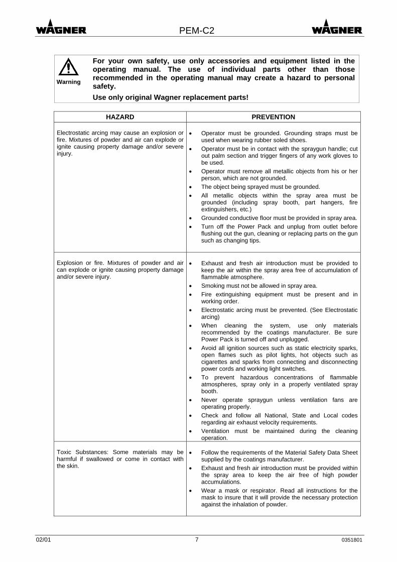
For your own safety, use only accessories and equipment listed in the operating manual. The use of individual parts other than those recommended in the operating manual may create a hazard to personal safety. Use only original Wagner replacement parts!
HAZARD PREVENTION
Electrostatic arcing may cause an explosion or fire. Mixtures of powder and air can explode or ignite causing property damage and/or severe injury.
• Operator must be grounded. Grounding straps must be
used when wearing rubber soled shoes. • Operator must be in contact with the spraygun handle; cut
out palm section and trigger fingers of any work gloves to be used.
• Operator must remove all metallic objects from his or her person, which are not grounded.
• The object being sprayed must be grounded. • All metallic objects within the spray area must be
grounded (including spray booth, part hangers, fire extinguishers, etc.)
• Grounded conductive floor must be provided in spray area.• Turn off the Power Pack and unplug from outlet before
flushing out the gun, cleaning or replacing parts on the gun such as changing tips.
Explosion or fire. Mixtures of powder and air can explode or ignite causing property damage and/or severe injury.
• Exhaust and fresh air introduction must be provided to
keep the air within the spray area free of accumulation of flammable atmosphere.
• Smoking must not be allowed in spray area. • Fire extinguishing equipment must be present and in
working order. • Electrostatic arcing must be prevented. (See Electrostatic
arcing) • When cleaning the system, use only materials
recommended by the coatings manufacturer. Be sure Power Pack is turned off and unplugged.
• Avoid all ignition sources such as static electricity sparks, open flames such as pilot lights, hot objects such as cigarettes and sparks from connecting and disconnecting power cords and working light switches.
• To prevent hazardous concentrations of flammable atmospheres, spray only in a properly ventilated spray booth.
• Never operate spraygun unless ventilation fans are operating properly.
• Check and follow all National, State and Local codes regarding air exhaust velocity requirements.
• Ventilation must be maintained during the cleaning operation.
Toxic Substances: Some materials may be harmful if swallowed or come in contact with the skin.
• Follow the requirements of the Material Safety Data Sheet
supplied by the coatings manufacturer. • Exhaust and fresh air introduction must be provided within
the spray area to keep the air free of high powder accumulations.
• Wear a mask or respirator. Read all instructions for the mask to insure that it will provide the necessary protection against the inhalation of powder.
02/01 7 0351801

PEM-C2
HAZARD PREVENTION
General
• Read all instructions and safety precautions before
operating. • Comply with all appropriate local, state and national
codes governing ventilation, fire prevention, and operation of Electrostatic equipment usage.
• The United States Government Safety Standards have been adopted under the Occupational Safety and Health Act. These standards, particularly the General Standards, Part 1910 and the Construction Standard, Part 1926, should be consulted.
• NFPA Standard No. 33 is to be followed when setting up your spray area. Contact the National Fire Protection Association, Batterymarch Park, Quincy, Massachusetts, 02269 for more information.
• Check with insurance company for additional requirements.
• Use only identical replacement parts. • Personnel must be given training in accordance with the
requirements of NFPA Standard No. 33 chapter 15. • It is the duty of all personnel responsible for the spray
equipment operation and maintenance to read and understand all safety information furnished with this equipment.
1.3 Harmless discharge When the high voltage is turned on, a glow or Corona discharge, that is only visible in a dark environment, occurs at the electrode tip. This physical phenomenon can be observed when the electrode approaches the grounded workpiece. This glow discharge does not provide any ignition power and does not have any influence on the handling of the installation. When the electrode approaches the workpiece, the control device automatically reduces the high voltage to a safe level or turns off the high voltage, depending on the setting.
nozzle
electrode
glow discharge
workpiece
If the finger comes in contact with the plastic parts of the spraygun, harmless discharges (so-called brush discharges) can occur. The charging of the plastic parts is caused by the high voltage electrostatic field of the gun. However, these discharges do not provide any ignition power.
02/01 8 0351801

PEM-C2
2. Preparing the spraygun for your application 2.1 Select the suitable nozzle system
Nozzle Workpiece Spray cloud Remarks
Deflector cone
Wire goods Gratings Aluminum cross sections
Round spray cloud: the size depends on the diameter of the deflector cone.
for powder quantities from 50 ... 300 g/min
Fan spray nozzle
Difficult workpieces: undercuts broken edges
Widely-spread fan spray.
for powder quantities from 50 ... 150 g/min
Round spray nozzle, extension 300 or 180 mm
Objects with large indentations: e.g. cabinets
The spray cloud depends on the nozzle used.
A deflector cone or a fan spray nozzle can be mounted to the extension.
The part numbers are listed in section 7. “Spare parts lists“ Chapter 5. “Mounting the extension“ describes how an extension is mounted.
02/01 9 0351801

PEM-C2
2.2 Connecting the spraygun Before you start making connections, switch off the high voltage generator. Refer to the operating instructions of the corresponding control unit for this.
to the electrical connectionpowder delivery
atomizing air
from the powder injectorat the control unit
from the control unit
• Connect the electrical cable to the control unit.
• Connect the powder hose to the spraygun an to the powder injector.
• Connect the hose for atomizing air to the spraygun and to the control unit.
2.3 Grounding Good grounding of the workpiece is necessary for optimum powder coating. A poorly grounded workpiece causes:
• very bad wrap-around • uneven coating • back-spray onto spraygun and user • dangerous electric charging of the workpiece
Warning
If the mains cable does not have a separate protective ground terminal, it is absolutely necessary to connect the control unit to the system ground by a separate grounding cable via the grounding screw at the back plate of the control unit! Sparks between workpiece and conveyor hooks (hangers) can occur if hooks or other hanger parts are not completely cleaned! These sparks can cause heavy radio frequency interference.
02/01 10 0351801

PEM-C2
2.4 Corona-Star The Corona-Star is a retrofit kit for the manual powder spraygun which helps to achieve a better surface quality. The formation of the orange peel effect can be reduced or eliminated for most powder types.
Caution
The assembling of the Corona-Star may only be carried out by trained personnel!
Proceed as follows:
B
C
D E
A
F
Connect gun cable A andadapter cable F
Connect adaptercable F at the
control unit
• Switch off the powder coating system and secure it against being switched on again
unintentionally.
• Connect the cable with the knurled screw B at the cover piece C.
• Attach the Corona-Star D to the gun housing E.
• Connect the gun cable A and the adapter cable F.
• Connect the adapter cable F at the control unit.
Caution
Ensure proper grounding of the gun fixture!
The system is now ready for operation again.
02/01 11 0351801

PEM-C2
3. Working with the spraygun 3.1 Starting up the spraygun
• Switch on the control unit.
• Make the necessary basic settings on the control unit.
• Check on the control unit whether the atomizing air is opened on pressing the trigger. As a result the deflector cone remains free from powder deposits and the cascade chamber is flushed.
• Refer to the operating instructions of the control unit for this.
Caution
To reduce wear, the total of feeding air and dosage air must range between 4 - 6 Nm3/h (141.2 - 211.8 ft3/h)!
• Hold the spraygun in the spray booth, press the trigger and set the powder volume and
the powder speed to a test piece by adjusting the volume of feeding air and dosage air.
• You can alter the size of the powder cloud during powdering by adjusting the atomizing air. The following illustration provides information on the effects of the feeding and dosage air volume on the powder volume.
feeding air volume
dosage air volume
feeding volume
+ =
+ =
+ = An exact description of how to set the air flows can be found in the operating instructions for the corresponding control units.
feeding airvolume
dosage air volume
total feeding volume to the spraygun(feeding air volume + dosage air volume + powder volume)
powder hose inner diameter
powder suction from the powder tank
02/01 12 0351801

PEM-C2
Recommended powder output volumes depending on the internal diameter of the hose
powder hose
inner diameter [mm]
feeding air + dosage air
[Nm3 / h]
powder output (standard values)
[g / min] 10 ca. 2.8 ... 4.8 ( 98.8 ... 169.4 ft3/h) ... 100 11 ca. 3.3 ... 5.8 (116.5 ... 204.7 ft3/h) 50 ... 250 12 ca. 3.7 ... 6.8 (130.6 ... 240.0 ft3/h) 100 ... 350
3.2 How to switch off the spraygun The spraygun is switched off in different ways, depending on the type of powder injector.
Hint
The spraygun should be blown through (flushed) and cleaned from powder deposits with every interruption of work. In this way powder deposits and surges on switching on again are to a great extent avoided.
The flushing procedure can be set on the control unit if the spraygun is connected to an EPG Digiflow in conjunction with the PJ-D1 powder injector. In this case the spraygun is blown free of powder as soon as the trigger is released. If the spraygun is operated with an EPG 2007 control unit and a PJ 2020 PRS powder injector, proceed as follows:
• Release the trigger on the spraygun so that the powder supply and high voltage generator are switched off.
• If you do not wish to alter the settings for the feeding air and dosage air, in order to carry on coating with the same powder cloud, pull out the powder injector from the powder container’s injector connection. No more powder will be delivered when switching on again.
• Press the trigger on the spraygun so that the spraygun is blown free of powder.
• Switch the control unit off and secure it against being switched on unintentionally.
02/01 13 0351801

PEM-C2
3.3 How to carry out a change of color All parts carrying powder in the entire coating system must be thoroughly cleaned of powder deposits on a change of color. In the following, only the procedure for the spraygun is described. Instructions on cleaning the other components can be found in the appropriate operating instructions.
• Switch off the control unit and secure it against being switched on again.
12
3
4
• If you do not use automatic flushing: Release the trigger on the spraygun so that the powder supply and high voltage generation are switched off. Pull the powder injector out of the powder container’s injector connection so that no powder can be delivered during flushing. Press the trigger on the spraygun so that the spraygun is blown free of powder. Switch the control unit off and secure it against being switched on unintentionally.
• Pull off deflector cone 1 from nozzle insert 3.
• Unscrew the outer nut 2 from the gun housing 4.
• Carefully draw the nozzle insert 3 out of the gun housing 4.
Caution
Take care that the nozzle insert is not damaged when removing and replacing it!
• Clean the parts which have been dismantled and the spraygun from powder deposits.
• Before re-assembling, check whether the contact points on the nozzle insert 3 and inside the metallic attachment 4 have been thoroughly cleaned, so that the tip of the electrode makes a conducting connection to the high voltage generator.
• Carefully re-fit the nozzle insert 3 in the gun housing 4 and tighten it up with the outer nut 2.
• Slide the deflector cone on to the nozzle insert again.
• The spraygun is again ready for operation and you may begin with the setting of the powder cloud in accordance with section 3.1.
02/01 14 0351801

PEM-C2
4. Maintenance and cleaning
WARNING
CAUTION
WHEN CLEANING THE ELECTROSTATIC SYSTEM, THESE SAFETY PROCEDURES MUST BE FOLLOWED. FAILURE TO FOLLOW THESE PROCEDURES MAY RESULT IN AN EXPLOSION/FIRE. • Turn power pack to the "OFF" position and unplug from
power source before starting to clean. • Exhaust and fresh air introduction must be maintained
during the clean up operation. • Keep cleaning materials in approved safety containers. • All personnel and cleaning equipment, including container
used in cleaning operation, must be grounded. • DO NOT turn on the POWER PACK until the cleaning
operation has been completed, all cleaning materials have been removed from spray area, and spray area is free of any mixtures of powder and air produced by the cleaning operation.
• If defects in the equipment are found, DO NOT use until repairs are completed.
• Clean equipment immediately after use. • NEVER IMMERSE SPRAYGUN OR PARTS OF IT IN
ANY FLUID AT ANY TIME. • Be sure the Power Pack is turned off and unplugged from
the power source. NOTE: • The powder passages of the spraygun should be cleaned
while cleaning the powder hose and powder pump, following instructions, provided with the powder pump (injector).
• See document No. PJ – D1 • Clean the spray tip by removing from spraygun, flushing
with air and replacing on spraygun.
4.1 Replacing the spraygun Before beginning replacing the spraygun, free it of powder deposits in accordance with section 3.3 .
Caution
Maintenance, repair or replacement of the spraygun may only be performed by trained personnel in a suitable location outside the hazard area!
The wear parts marked with (*) in the spare parts list of the spraygun must be regularly checked and replaced if necessary.
• Switch off the control unit or the high voltage generator and disconnect the gun cable from the control unit.
• Disconnect the hoses for the powder delivery and the atomizing air from the spraygun.
• Exchange the spraygun for a new one and assemble it in reverse order.
02/01 15 0351801

PEM-C2
4.2 Cleaning the spraygun and replace the wear parts
4
12
3
5
• Pull off deflector cone 1 from nozzle insert 3. • Unscrew the outer nut 2 from the gun housing 5.• Carefully draw the nozzle insert 3 out of the gun
housing 5. • Separate the protective wedge 4 from the
nozzle insert 3.
Caution
Never place the spraygun or parts of it into any wet cleaning agent!
• Clean the dismantled parts and the spraygun of powder deposits.
• Normally it is only necessary to check the protective wedge 4 for wear, and to replace it with a new one if necessary.
• Check before re-assembling whether the contact points on the nozzle insert 3 and the inside of the gun housing 5 have been thoroughly cleaned, so that the tip of the electrode makes a conducting connection to the high voltage generator.
• Carefully re-fit the nozzle insert in the gun housing and tighten it up with the outer nut.
• Slide the deflector cone onto the nozzle insert again.
• The spraygun is again ready for operation.
02/01 16 0351801

PEM-C2
5. Mounting the extension
Caution
Always select a spraygun which has been thoroughly cleaned when mounting a round spray nozzle extension. A better alternative is to only selected a new spraygun in such cases.
12
3
4
• Pull off deflector cone 1 from nozzle insert 3. • Unscrew the outer nut 2 (standard) from the gun
housing 4 and put aside. The outer nut is not necessary for the extension.
• Carefully draw the nozzle insert 3 out of the gun housing 4.
56
• Unscrew the outer nut 5 from the extension 6.
15
3
6
7
4
• Slide the extension 6 into the gun housing 4 and tighten it up with the outer nut 7.
• Carefully re-fit the nozzle insert 3 in the extension 6 and tighten it up with the outer nut 5.
• Slide the deflector cone 1 on to the nozzle insert 3.
02/01 17 0351801
PEM-C2
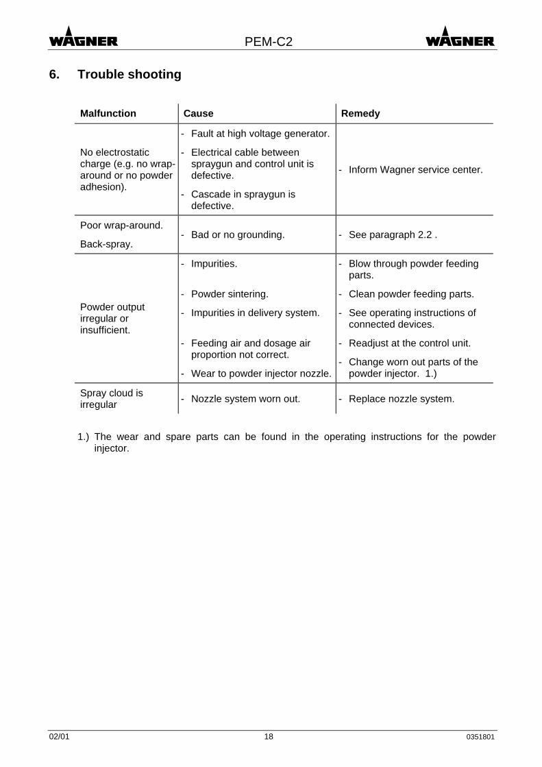
6. Trouble shooting
Malfunction Cause Remedy
No electrostatic charge (e.g. no wrap-around or no powder adhesion).
- Fault at high voltage generator.
- Electrical cable between spraygun and control unit is defective.
- Cascade in spraygun is defective.
- Inform Wagner service center.
Poor wrap-around.
Back-spray. - Bad or no grounding. - See paragraph 2.2 .
Powder output irregular or insufficient.
- Impurities.
- Powder sintering.
- Impurities in delivery system.
- Feeding air and dosage air proportion not correct.
- Wear to powder injector nozzle.
- Blow through powder feeding parts.
- Clean powder feeding parts.
- See operating instructions of connected devices.
- Readjust at the control unit.
- Change worn out parts of the powder injector. 1.)
Spray cloud is irregular - Nozzle system worn out. - Replace nozzle system.
1.) The wear and spare parts can be found in the operating instructions for the powder
injector.
02/01 18 0351801

PEM-C2
7. Spare parts lists 7.1 How to order
Faulty and useless parts are replaced according to our general delivery conditions. To ensure a correct spare part order and delivery, the following information is required:
- Billing address - Delivery address - Name of contact persons for further inquiries - Shipping method - Quantity, part number and description
7.2 Spraygun PEM-C2 4
1/1
32
4/24/1
1
Item Part No. Description
0351 021 Spraygun PEM-C2
1 0351 900 * Nozzle insert ** 1/1 0351 339 * Wedge
2 0351 309 Outer nut 3 0351 225 * Deflector cone (∅17)) 3 0351 226 * Deflector cone (∅25) 3 0351 227 * Deflector cone (∅32)) 4 0351 901 * Fan spray nozzle **
4/1 0351 232 * Fan spray nozzle 4/2 0351 346 * Air nozzle
* wear part ** only available as a set
02/01 19 0351801

PEM-C2
7.3 Round spray nozzle, extension
1/1
1
Item Part No. Description
1 0351 904 * Round spray nozzle, extension 300 mm **
1 0351 915 * Round spray nozzle, extension 180 mm **
1/1 0351 372 Outer nut * wear part ** only available as a set
7.4 Corona-Star Retrofit-Set 23 1
Item Part No. Description
0351 110 Corona-Star Retrofit-Set **
1 0259 608 Adapter cable 2 0351 111 Corona-Star assembly 3 0260 296 * Electrode Corona-Star (included in item 2)
* wear part ** only available as a set
02/01 20 0351801

PEM-C2
8. Specification
Weight: 498 g
Electrical: input voltage: max. 22 Vpp input current: max. 0.9 A frequency: 19 ... 30 kHz output voltage: max. 100 kV DC output current: max. 160 µA DC polarity: negative design: according to EN 50050 protection class: IP 54
Pneumatic: input air pressure (atomizing air): max. 3 bar powder output volume: max. 450 g/min
Compressed air quality according to ISO 8573.1: residual water content in compressed air: max. 1.3 g H2O/Nm3 at a dew point of 7 °C residual oil content in compressed air: max. 0.01 mg oil/Nm3 residual dust content in compressed air: max. 1 mg dust/Nm3
Hint
Volume measures: All volume indications (m3/h) are Nm3/h. (norm cubic meters per hour). One cubic meter of a gas at 0 °C and 1.013 bar is called norm cubic meter. 1 Nm3/h = 35.3 ft3/h
Ambient conditions: If low temperature powders are used, the ambient temperature may have to be lower than 30 °C.
02/01 21 0351801
PEM-C2
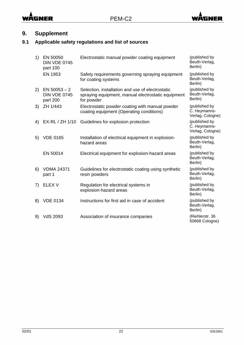
9. Supplement 9.1 Applicable safety regulations and list of sources
1) EN 50050
DIN VDE 0745 part 100
Electrostatic manual powder coating equipment (published by Beuth-Verlag, Berlin)
EN 1953 Safety requirements governing spraying equipment for coating systems
(published by Beuth-Verlag, Berlin)
2) EN 50053 – 2 DIN VDE 0745 part 200
Selection, installation and use of electrostatic spraying equipment, manual electrostatic equipment for powder
(published by Beuth-Verlag, Berlin)
3) ZH 1/443 Electrostatic powder coating with manual powder coating equipment (Operating conditions)
(published by C. Heymanns-Verlag, Cologne)
4) EX-RL / ZH 1/10 Guidelines for explosion protection (published by C. Heymanns-Verlag, Cologne)
5) VDE 0165 Installation of electrical equipment in explosion-hazard areas
(published by Beuth-Verlag, Berlin)
EN 50014 Electrical equipment for explosion-hazard areas (published by Beuth-Verlag, Berlin)
6) VDMA 24371 part 1
Guidelines for electrostatic coating using synthetic resin powders
(published by Beuth-Verlag, Berlin)
7) ELEX V Regulation for electrical systems in explosion-hazard areas
(published by Beuth-Verlag, Berlin)
8) VDE 0134 Instructions for first aid in case of accident (published by Beuth-Verlag, Berlin)
9) VdS 2093 Association of insurance companies (Riehlerstr. 36 50668 Cologne)
02/01 22 0351801

PEM-C2
9.2 Warranty
What is covered by this warranty: Faulty parts are replaced according to our general delivery conditions. Within the applicable warrant period, Wagner will repair or replace, defective parts without charge if such parts are returned with transportation charges prepaid to the nearest authorized service center. If Wagner is unable to repair this product so as to conform to this limited warranty after a reasonable number of attempts, Wagner will provide, either a replacement for this product or a full refund of the purchase price of this product.
These remedies are the sole and exclusive remedies available for breach of express and implied warranties.
What is not covered by this warranty: This warranty does not cover any damage or defects: 1. Caused by use or installation of repair or replacement parts or accessories not
manufactured by Wagner, 2. Caused by repair performed by anyone other than a Wagner authorized service center, or 3. Caused by or related to abrasion, corrosion, abuse, misuse, negligence, accident, normal
wear, faulty installation or tampering in a manner which impairs normal operation.
Limitation of remedies: IN NO CASE SHALL WAGNER BE LIABLE FOR ANY INCIDENTAL, SPECIAL OR CONSEQUENTIAL DAMAGES OR LOSS, INCLUDING TRANSPORTATION COSTS, WHETHER SUCH DAMAGES ARE BASED UPON A BREACH OF EXPRESS OR IMPLIED WARRANTIES, BREACH OF CONTRACT, NEGLIGENCE, STRICT TORT, OR ANY OTHER LEGAL THEORY.
Disclaimer of implied warranties: THE FOREGOING WARRANTIES ARE IN LIEU OF ALL OTHER WARRANTIES, EXPRESS OR IMPLIED, INCLUDING BUT NOT LIMITED TO THE IMPLIED WARRANTIES OF MERCHANTABILITY AND FITNESS FOR A PARTICULAR PURPOSE.
No ability to transfer: This warranty is extended to the original purchaser only and is not transferable.
Your rights under state law: Some states do not allow limitations on how long an implied warranty lasts or the exclusion of incidental or consequential damages, so the above limitation and exclusion may not apply to you. This warranty gives you specific legal rights, and you may also have other rights which vary from state to state.
Date of sale Stamp and signature
02/01 23 0351801

PEM-C2
02/01 24 0351801

PEM-C2
02/01 25 0351801


Directory of Wagner subsidiaries
USA:
WAGNER Systems Inc. Phone ++1-630-784-8900 175 Della Court Fax ++1-630-784-8970 Carol Stream, IL 60188 USA
Great Britain:
WAGNER Spraytech (UK) Ltd. Phone ++44-1295-265-353 Unit 3 Haslemere Way Fax ++44-1295-269-861 Tramway Industrial Estate Banbury, Oxon OX 16 8TY Great Britain
Hong Kong:
WAGNER Spraytech (HK) Ltd. Phone ++852-2515-2862 Unit G, 20 F, Seabright Plaza Fax ++852-2889-1792 9-23 Shell Street North Point Hong Kong
Japan:
WAGNER Spraytech Japan Ltd. Phone ++81-720-74-8181 2-35, Shinden Nishimachi Fax ++81-720-74-3426 Daito Shi Osaka 574-0057 Japan
Sweden:
Wagner Sverige AB Phone ++46-42-150020 Muskötgatan 19 Fax ++46-42-150035 S-254 66 Helsingborg Sweden
Switzerland:
J. WAGNER AG Phone ++41-71-7572211 Postfach 663 Fax ++41-71-7572222 Industriestrasse 22 CH-9450 Altstätten Switzerland
Germany:
J. WAGNER GmbH Phone ++49-7544-505-0 Postfach 1120 Fax ++49-7544-505-200 Otto-Lilienthal-Str. 18 D-88677 Markdorf Germany
Italy:
WAGNER Itep S.p.a. Phone ++39-0341-210100 Via Santa Vecchia 109 Fax ++39-0341-210200 I-22049 Valmadrera Italy