power factor correction (pfc) and harmonics...
TRANSCRIPT
232
Chapter 08Power factor correction (PFC) and harmonics filter
Power factor correction (PFC) and harmonics filter08Prophi® power factor controller
The universal capacitor monitoring system
PFC power capacitors
Automatic power factor correction systems without reactors
Power factor correction spare parts and accessories
Automatic de-tuned power factor correction systems
Dynamic power factor correction systems (real time PFC)
• Optimised control for longer service life
• Protection of capacitors and PFC systems
• 3-phase power capacitors in aluminium cans• Power capacitors in sheet steel housing – without reactors• Power capacitors in sheet steel cabinet – 7 % de-tuned• Power capacitors in sheet steel cabinet – 14 % de-tuned
• Automatic power factor correction, compact design, up to 120 kvar• Automatic power factor correction, modular design (up to 500 kvar)• Automatic power factor correction, extractable module, up to 100 kvar
• Component selection table for a nominal voltage 400 V – 50 Hz• Accessory – Passive harmonics filter
• Automatic de-tuned power factor correction (harmonics filter), compact design• 7 % de-tuned power factor correction (harmonics filter)• 14 % de-tuned power factor correction (harmonics filter)• De-tuned capacitor modules
• 7 % de-tuned dynamic power factor correction• 14 % de-tuned dynamic power factor correction• De-tuned dynamic PFC module
Page 235
Page 243
Page 245
Page 253
Page 259
Page 267
Page 275
08
233
Power factor correction (PFC) and harmonics filter✔
Chapter 08Power factor correction (PFC) and harmonics filter

234
Chapter 08Power factor correction (PFC) and harmonics filter
Individual PFC
• A suitably sized capacitor will be connected in parallel to each inductive load• Relieving of the load on the supply line as well as the switching equipment• No separate switching equipment required for the capacitor and
no controller required• Economic with longer duty cycles and greater power draw
Group PFC
• Will be implemented with load groups with the same operational behaviour • For multiple inductive loads, that are always operated together• The supply lines and group switches will be relieved of reactive current and the simultaneity factor results in a smaller capacitor size
Automatic central PFC (APFC)
• The central PFC will be integrated into the main LV distribution• Near constant, good power factor that adapts automatically through a power
factor controller via contactors or thyristor switches• The output of the capacitors installed will be better utilised• Better adaptation of the capacitor power to the reactive power demand• Networks with harmonics can be more easily detuned through APFC
Mixed PFC
• Combination of individual, group and central PFC
Types of power factor correction (PFC)
Controller
Controller
08
235
Chapter 08Prophi® power factor controller
Prophi® power factor controller
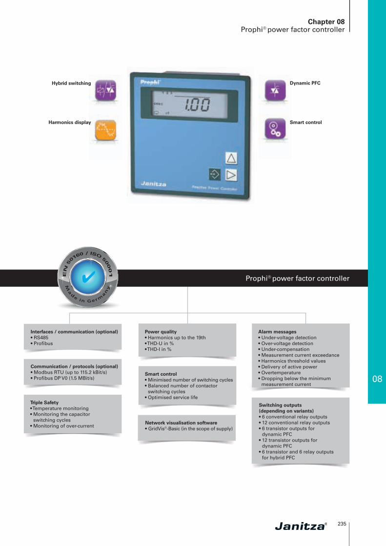
Hybrid switching
Harmonics display
Dynamic PFC
Smart control
Switching outputs (depending on variants)• 6 conventional relay outputs• 12 conventional relay outputs• 6 transistor outputs for
dynamic PFC• 12 transistor outputs for
dynamic PFC• 6 transistor and 6 relay outputs
for hybrid PFC
Interfaces / communication (optional)• RS485• Profibus
Communication / protocols (optional)• Modbus RTU (up to 115.2 kBit/s)• Profibus DP V0 (1.5 MBit/s)
Alarm messages• Under-voltage detection• Over-voltage detection• Under-compensation• Measurement current exceedance• Harmonics threshold values• Delivery of active power• Overtemperature• Dropping below the minimum
measurement current
Power quality • Harmonics up to the 19th• THD-U in %• THD-I in %
Smart control• Minimised number of switching cycles• Balanced number of contactor
switching cycles• Optimised service life
Triple Safety• Temperature monitoring• Monitoring the capacitor
switching cycles• Monitoring of over-current
Network visualisation software• GridVis®-Basic (in the scope of supply)
✔

236
Chapter 08Prophi® power factor controller
• Automatically controlled power factor correction• Detuned power factor correction• Harmonics filter• Voltage stabilisation by means of dynamic PFC• Mixed operation (hybrid switching) contactors and thyristor switching
Areas of application
Main features
• Automatic or manual configuration• Display of U, I, f, Q, P, S, cosphi, all odd current and voltage harmonics,
1 – 19th harmonics• Display of the indirectly measured capacitor currents• Display of the switching cycles per capacitor stage• Display of the total switch-on duration per capacitor stage• Zero voltage triggering within 15 ms• Degree of reactors in % for each stage, programmable from 0 to 20 %• Setting of the discharge time for all stages from 0 to 1200 sec.• Capacitor outputs individually programmable• Temperature sensor for fan control• Overtemperature shut-down programmable• Control of external semi-conductor switching (max. 50 switching operations per second)• Current transformer input for 1 A; 5 A• Password protection• External, changable target cosphi 1 and 2 (except 6R / 6T)
Alarm output programmable for ...
• Under-voltage detection• Over-voltage detection• Under-compensation• Measurement current exceedance• Dropping below the minimum measurement current• Harmonics threshold values• Delivery of active power• Overtemperature
Functional principle
• Single-phase, electronic measurement system• Acquisition of the active and reactive current portion of the network via
the current and voltage circuit• Reactive power will be calculated with the current from a phase conductor
and the voltage between two phase conductors
Fig.: Device rear side Prophi® 12RS
08
237
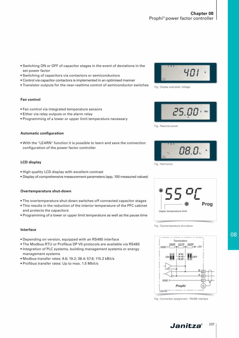
• Switching ON or OFF of capacitor stages in the event of deviations in the set power factor
• Switching of capacitors via contactors or semiconductors • Control via capacitor contactors is implemented in an optimised manner• Transistor outputs for the near-realtime control of semiconductor switches
Fan control
• Fan control via integrated temperature sensors• Either via relay outputs or the alarm relay • Programming of a lower or upper limit temperature necessary
Automatic configuration
• With the "LEARN" function it is possible to learn and save the connection configuration of the power factor controller
LCD display
• High quality LCD display with excellent contrast • Display of comprehensive measurement parameters (app. 100 measured values)
Overtemperature shut-down
• The overtemperature shut-down switches off connected capacitor stages • This results in the reduction of the interior temperature of the PFC cabinet
and protects the capacitors• Programming of a lower or upper limit temperature as well as the pause time
Interface
• Depending on version, equipped with an RS485 interface• The Modbus RTU or Profibus DP V0 protocols are available via RS485• Integration of PLC systems, building management systems or energy
management systems• Modbus transfer rates: 9.6; 19.2; 38.4; 57.6; 115.2 kBit/s• Profibus transfer rates: Up to max. 1.5 Mbit/s
Chapter 08Prophi® power factor controller
Fig.: Display examples: Voltage
Fig.: Reactive power
Fig.: Harmonics
Fig.: Overtemperature shut-down
Fig.: Connection assignment - RS485 interface
Upper temperature limit

238
Side view
Chapter 08Prophi® power factor controller
Dimension diagrams
Typical connection
Prophi
Supply Loads
Modbus- or Profibus-Master
Alarm output
changeover
Motor ofventilator
Contact opensduring alarm
Internaltemperature sensor
Rear side view
All dimensions in mm
Fig.: Connection example power factor controller Prophi® 12RS (item no. 52.08.008) with voltage measurement L2–L3, 12 relay outputs, target cos(phi) changeover, alarm output and RS485 interface
Target cosphichangeover

08
239
Chapter 08Prophi® power factor controller
Device overview and technical data
Prophi® 6R Prophi® 12R Prophi® 6T Prophi® 12 T
Item number 52.08.002 52.08.003 52.08.005 52.08.006Measurement and auxiliary voltage 400 V AC (+10 %, -15 %)*1 • • • •
Changeover target cosphi 1/2 - • - •
OutputsRelay outputs (conventional) 6 12 - -
Transistor outputs (dynamic) - - 6 12
Interface Modbus or ProfibusRS485 *2, *4 - - - -
Prophi® 6T6R Prophi® 12RS Prophi® 6T6RS Prophi® 12TS
Item number 52.08.007 52.08.008 52.08.009 52.08.091Measurement and auxiliary voltage 400 V AC (+10 %, -15 %) *1 • • • •
Changeover target cosphi 1/2 • • • •
OutputsRelay outputs (conventional) 6 12 6 -
Transistor outputs (dynamic) 6 - 6 12
Interface Modbus or ProfibusRS485 *2, *4 - • • •
Software GridVis®-Basic (included in the scope of supply) - • *3 • *3 • *3
*1 Optional measurement and auxiliary voltage 100 V, 110 V, 200 V, 230 V, 440 V AC (+10 %,-15 %).
*2 Not possible with 50 switching operations per second.
*3 Optional additional functions with the packages GridVis®-Professional, GridVis®-Enterprise and GridVis®-Service.
*4 Modbus or Profibus possible, please stipulate when ordering.
General Prophi®
Use in low and medium voltage networks L-N or L-L •
Accuracy voltage measurement (1-phase, L-N or L-L) 0.5 %
Accuracy current measurement (1-phase) 0.5 %
Accuracy cosphi measurement (sum L1-L3) 1 % *5,*6
Accuracy power measurement (sum L1-L3) 1 %
Accuracy frequency measurement 0,5 % *6
Accuracy harmonics measurement 2 %
RMS – momentary valueCurrent, voltage, frequency •
Effective, reactive and apparent power •
Power factor •
Recording of the mean valuesPower factor •
Power quality measurementHarmonics per order / current and voltage, 1-phase 1st – 19th, odd
Distortion factor THD-U in %, 1-phase •
Distortion factor THD-I in %, 1-phase •
Measured data recordingMean, minimum, maximum values •
Displays and inputs / outputsDigital display, 3 buttons •
Relay outputs (as switch output)6 or 12
See overview of devices
Transistor outputs (as switch output)6 or 12
See overview of devices
Alarm output (as switch output) 1
Digital input (for tariff changeover)1
See overview of devices
Temperature sensor (internal) 1
*5 Applies to input currents > 0.2 A and in the cosphi range 0.85 to 1.00.*6 In the range from -10 to +18 °C and 28 to 55 °C an additional error of ±0,2 ‰ of the measurement value per
K must be taken into account.
240
Chapter 08Prophi® power factor controller
Technical dataSupply voltage L-L, L-N AC See overview of devices
Measurement in which quadrants 4
Networks TN, TT, (IT)
Measurement in multi-phase networks 3 ph
Measured voltage inputOvervoltage category CAT III
Measured range, voltage L-N, AC (without potential transformer)
See overview of devices
Measured range, voltage L-L, AC (without potential transformer)
See overview of devices
Voltage tolerance range - 15 ... +10 %
Back-up fuse 2 A … 10 A T
Measurement surge voltage 4 kV
Test voltage relative to ground 2,200 V AC
Frequency measuring range 45 ... 65 Hz
Power consumption max. 7 VA
Sampling rate 2 kHz (at 50 Hz)
Measured current inputSignal frequency 45 Hz ... 1,200 Hz
Nominal current at .../5 A (…/1 A) 5 A (1 A)
Minimum measurement current 10 mA
Upper measurement current 5.3 A (sinusoidal)
Overloading 180 A for 2 sec.
Measurement rate 30 (50) measurements / sec.
Power consumption approx. 0.2 VA
Updating the display 1 time per second
Zero voltage triggering < 15 ms
Inputs and outputs
Number of digital inputs (for tariff changeover)
1, see overview of devices
Relay outputs (as switch output) 6 or 12, see overview of devices
Back-up fuse 6.3 AT
Switching voltage max. 250 V AC
Switching power max. 1,000 W
Communication
Interface
RS485: 9.6; 19.2; 38.4; 57.6; 115.2 kbps See overview of devices
Profibus DP V0: 9.6 kbps to 1.5 Mbps See overview of devices
Protocols
Modbus RTU •
Profibus DP V0 •
Software GridVis®-Basic*3
Online graphs •
Historical graphs •
Databases (Janitza DB, Derby DB); MySQL, MS SQL with higher GridVis® versions)
•
Manual reports •
Topology views •
Manual reading •
Graph sets •
Error messagesUnder-voltage •
Over-voltage •
Dropping below the minimum measurement current •
Measurement current exceedance •
Insufficient compensation power •
Delivery of active power •
Harmonics threshold values •
Overtemperature •
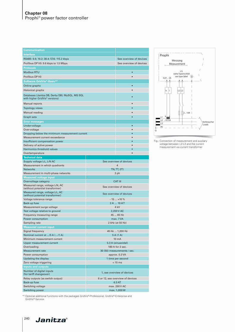
Prophi
MessungMeasurement
0,01 .. 5A
L/Lsiehe Typenschild
see type label
../5(1)AL1L2L3
PE
k l
2 .. 10A
VerbraucherLoads
k l L2 L3
Fig.: Connection of measurement and auxiliary voltage between L2-L3 and the current measurement via current transformer
*3 Optional additional functions with the packages GridVis®-Professional, GridVis®-Enterprise and GridVis®-Service.

08
241
Chapter 08Prophi® power factor controller
Max. switching frequency 0.25 Hz
Mechanical service life > 30 x 106 switching cycles
Electrical service life > 2.8 x 10⁵ switching cycles
Transistor outputs (as switch output) 6 or 12, see overview of devices
Switching voltage 5 ... 30 V DC
Switching current max. 50 mA
Max. switching frequency 50 Hz
Alarm output (as switch output) 1
Temperature sensor (internal) 1
Target cosphi changeover (current consumption) approx. 2.5 ... 10 mA
Mechanical propertiesWeight 1000 g
Device dimensions in mm (H x W x D) 144 x 144 x 49
Protection class per IEC 60529 Front: IP65, Rear: IP20
Installation Front panel installation
Connecting phase (U / I), Single core, multi-core, fine-stranded Terminal pins, core end sheath
0.08 to 2.5 mm²1.5 mm²
FeaturesDisplay of capacitor currents •
Display of switch-on times for the individual stages
•
Display of switching cycles per stage •
Zero voltage triggering •
Automatic configuration •
Password protection •
Environmental conditionsTemperature range Operation: -10 … +55 °C *7
Storage: -20 … +60 °C
Relative humidity 15 to 95 %
Operating altitude 0 ... 2,000 m above sea level
Degree of pollution 2
Mounting position any
Electromagnetic compatibility
Electromagnetic compatibility of equipment Directive 2004/108/EC
Electrical appliances for application within particular voltage limits
Directive 2006/95/EC
Equipment safetySafety requirements for electricalequipment for measurement, regulation, controland laboratory use –Part 1: General requirements
IEC/EN 61010-1
Part 2 – 008: Particular requirements for testing and measuring circuits
IEC/EN 61010-1-08
Protection class I = Device with protective conductor
Noise immunityIndustrial environment DIN EN 61326-1, Table 2; (IEC 61326-1)
EmissionsClass B: Residential environment DIN EN 61326-1; (IEC 61326-1)
Class A: Industrial environment DIN EN 61326-1; (IEC 61326-1)
SafetyEurope CE labelling
Comment: For detailed technical information please refer to the operation manual and the Modbus address list.
*7 Devices with the "RS485 interface" option are only suitable for an operating temperature range of -10 to +50 °C.
13
14
T6,3
A
max. 300V
Fig.: Connection assignment, alarm output

242
Chapter 08Power factor correction (PFC)
M~
M~Avoidance of reactive energy costs and penalties from the power supply companies.
cosphi = 0.7
cosphi = 1
Fig.: Active and reactive power in the mains with PFC
Effective power (P) Effective power (P)
Reactive power (Q) Reactive power (Q)
Effective power (P) Effective power (P)
Rea
ctiv
e p
ow
er (
Q)
Optimized usage of:
• Generators• Power transformers• Supply lines• Distribution equipment
Janitza PFC
Utilities
Utilities
Lower losses, lower voltage drop, lower energy cost!

08
243
Chapter 08Capacitor monitoring
The universal capacitor monitoring system
Safety
Monitoring
Modbus-Ethernet gateway
128 MB memory
Events
Homepage
2 digital outputs• Pulse output kWh / kvarh• Switch output• Threshold value output• Logic output
Safety• Timely detection of capacitor aging• Timely replacement of contactors• Prevention of fire damage• Prevention of downtimes
Continuous capacitor monitoring• Over-current limit value• Under-current limit value• Unbalance limit value• Temperature limit value• Harmonics limit value• Voltage limit value• Number of switching cycles
Thermistor input• PT100, PT1000, KTY83, KTY84
Interfaces• Ethernet• RS232• RS485
Communication• Profibus (DP/ V0)• Modbus (RTU, TCP, Gateway)• TCP/IP• BACnet (optional)• HTTP (Homepage)• FTP (file transfer)• SNMP• TFTP• NTP (time synchronisation)• SMTP (email function)• DHCP
Measured data memory• 128 MByte Flash• 16 MB RAM
Power quality • Harmonics up to 40th harmonic• Short term interruptions• Transient recorder (> 50 μs)• Inrush currents (> 20 ms)• Imbalance• Full cycle RMS
recordings (up to 4.5 min.)
✔

244
Chapter 08Capacitor monitoring
PFC protection – Capacitor monitoring Item no.: 52.16.300
• Increases the safety of PFC systems• Monitoring of all overload scenarios by means of the UMG 604E• Timely detection of capacitor overloading as well as short circuits
Main features
• Measurement 3-phase, 3 CTs in the supply line for the PFC system• PFC-APP (Jasic® monitoring software on UMG 604E)• Monitoring of: Short-circuit to ground, over-current and under-current,
overvoltage, unbalance, switching frequency, temperature, etc.• Additional, comprehensive network analysis functions • Extensive analysis options via GridVis®-Basic software• Integration into networks with Ethernet or RS485-Modbus RTU• Flexible alarm system with monitoring of up to 32 measured values• Menu-driven user guidance in plain text on the UMG 604E homepage
Fig.: Monitoring of limit values via UMG 604 homepage
Fig.: Capacitor monitoring in a PFC system
Fig.: Monitoring of short-circuits to ground, temperature, over-current etc. with the power analyser UMG 604E
08
245
Chapter 08PFC power capacitors
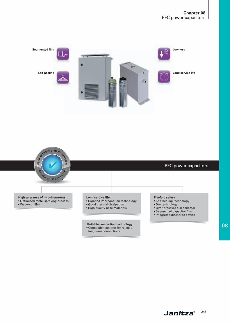
PFC power capacitors
Segmented film
Self-healing
Low loss
Long service life
High tolerance of inrush currents• Optimised metal spraying process• Wave-cut film
Fivefold safety• Self-healing technology• Dry technology• Over-pressure disconnector• Segmented capacitor film• Integrated discharge device
Long service life• Highend impregnation technology• Good thermal dissipation• High quality base materials
Reliable connection technology• Connection adapter for reliable
long term connections
✔

246
Chapter 083-phase power capacitors
• Motor fixed PFC• Group PFC• Automatic power factor correction• Detuned power factor correction systems• Harmonics filter• Dynamic power factor correction systems
Areas of application
Main features
Fivefold safety
• Self-healing technology• Dry technology• Over-pressure disconnector• Segmented capacitor film• Integrated discharge device
Long service life (up to 170,000 hours) and high operational reliability
• Highend impregnation technology• Excellent thermal dissipation• High quality base materials
Reliable connection technology
• Connection adapter for reliable long term connections
High inrush currents withstand capability
• Optimised metal spraying process• Wave-cut film design
High of overload withstand capability
• Max. over-current: 2.2 In• Max. inrush current: 300 x In
Fig.: Principle of over-pressure disconnector
Fig.: Self-healing, segmented capacitor film
Fig.: The connection adapter offers a lowtransfer resistance and a permanent,fixed electrical and mechanical contact
08
247
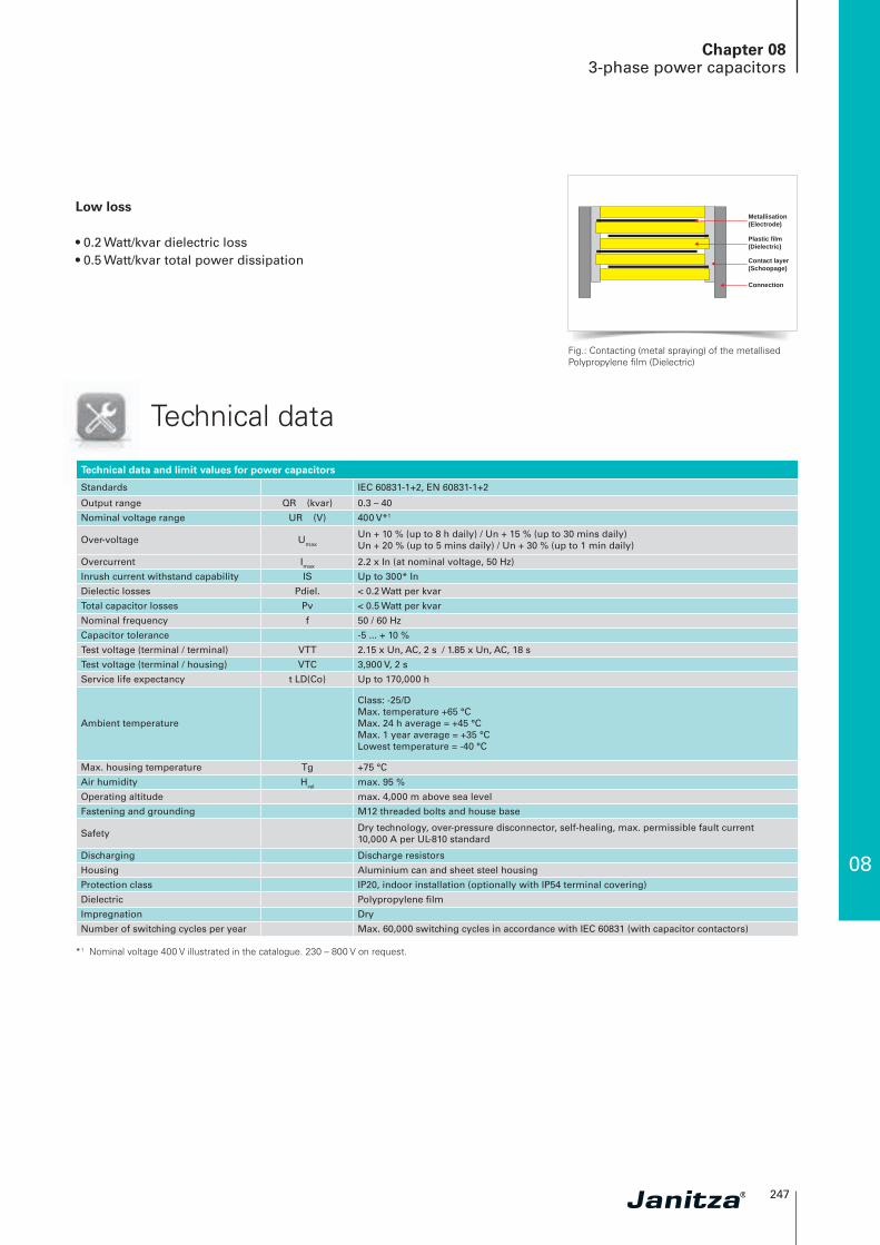
Low loss
• 0.2 Watt/kvar dielectric loss• 0.5 Watt/kvar total power dissipation
Chapter 083-phase power capacitors
*1 Nominal voltage 400 V illustrated in the catalogue. 230 – 800 V on request.
Technical data and limit values for power capacitors
Standards IEC 60831-1+2, EN 60831-1+2
Output range QR (kvar) 0.3 – 40
Nominal voltage range UR (V) 400 V*1
Over-voltage Umax
Un + 10 % (up to 8 h daily) / Un + 15 % (up to 30 mins daily)Un + 20 % (up to 5 mins daily) / Un + 30 % (up to 1 min daily)
Overcurrent Imax 2.2 x In (at nominal voltage, 50 Hz)
Inrush current withstand capability IS Up to 300* In
Dielectic losses Pdiel. < 0.2 Watt per kvar
Total capacitor losses Pv < 0.5 Watt per kvar
Nominal frequency f 50 / 60 Hz
Capacitor tolerance -5 ... + 10 %
Test voltage (terminal / terminal) VTT 2.15 x Un, AC, 2 s / 1.85 x Un, AC, 18 s
Test voltage (terminal / housing) VTC 3,900 V, 2 s
Service life expectancy t LD(Co) Up to 170,000 h
Ambient temperature
Class: -25/DMax. temperature +65 °CMax. 24 h average = +45 °CMax. 1 year average = +35 °CLowest temperature = -40 °C
Max. housing temperature Tg +75 °C
Air humidity Hrel max. 95 %
Operating altitude max. 4,000 m above sea level
Fastening and grounding M12 threaded bolts and house base
Safety Dry technology, over-pressure disconnector, self-healing, max. permissible fault current 10,000 A per UL-810 standard
Discharging Discharge resistors
Housing Aluminium can and sheet steel housing
Protection class IP20, indoor installation (optionally with IP54 terminal covering)
Dielectric Polypropylene film
Impregnation Dry
Number of switching cycles per year Max. 60,000 switching cycles in accordance with IEC 60831 (with capacitor contactors)
Technical data
Metallisation(Electrode)
Plastic film(Dielectric)
Contact layer(Schoopage)
Connection
Fig.: Contacting (metal spraying) of the metallised Polypropylene film (Dielectric)

248
Chapter 083-phase power capacitors
3-phase power capacitors in aluminium cans
Main features
• PFC power capacitors in aluminium cans• Delta connection• With discharge resistors• Long service life, low loss
Dimension diagrams
Capacitor with d = 60 / 70 mmfor connection with flat connector 6.3 x 0.8 mm
Capacitor with connection adapter ASS 1d = 60 / 70 mm
Capacitor with d = 85 mmfor connection with flat connector 9.5 x 1.2 mm
Capacitor with connection adapter ASS 2d = 85 mm
Protective cap SK60 / SK70 for Capacitor with d = 60 / 70 mm(not available for capacitors with d = 85 mm)
08
249
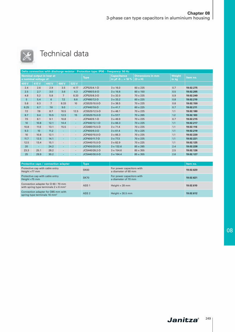
Chapter 083-phase can type capacitors in aluminium housing
Technical data
Delta connection with discharge resistor - Protection type: IP00 – Frequency: 50 Hz
Nominal output in kvar at a nominal voltage of:
TypeCapacitance in µF -5 ... + 10 %
Dimensions in mm (D x H)
Weight in kg
Item no.
400 V 415 V 440 V 480 V 525 V2.4 2.6 2.9 3.5 4.17 JCP525/4.1-D 3 x 16.0 60 x 225 0.7 19.02.275
2.5 2.7 3.0 3.6 4.3 JCP480/3.6-D 3 x 16.6 60 x 150 0.5 19.02.205
4.8 5.2 5.8 7 8.33 JCP525/8.3-D 3 x 32.0 70 x 225 0.9 19.02.249
5 5.4 6 7.2 8.6 JCP480/7.2-D 3 x 33.2 60 x 225 0.8 19.02.210
5.8 6.3 7 8.33 10 JCS525/10.0-D 3 x 38.5 70 x 225 0.8 19.02.150
6.25 6.7 7.6 9.0 - JCP440/7.6-D 3 x 41.7 60 x 225 0.7 19.02.211
7.2 7.8 8.7 10.5 12.5 JCS525/12.5-D 3 x 48.1 70 x 225 1.1 19.02.180
8.7 9.4 10.5 12.5 15 JCS525/15.0-D 3 x 57.7 70 x 265 1.2 19.02.103
7.5 8.1 9.1 10.8 - JCP440/9.1-D 3 x 49.9 70 x 225 0.7 19.02.215
10 10.8 12.1 14.4 - JCP440/12.1-D 3 x 66.3 70 x 225 1.1 19.02.217
10.8 11.6 13.1 15.5 - JCS480/15.5-D 3 x 71.4 70 x 225 1.1 19.02.116
9.3 10 11.2 - - JCP400/9.3-D 3 x 61.4 70 x 225 1.1 19.02.219
10 10.8 12.1 - - JCP400/10.0-D 3 x 66.3 70 x 225 1.1 19.02.220
11.7 12.5 14.1 - - JCP400/11.7-D 3 x 77.3 70 x 225 1.1 19.02.221
12.5 13.4 15.1 - - JCS440/15.0-D 3 x 82.9 70 x 225 1.1 19.02.125
20 - 24.2 - - JCP400/20.0-D 3 x 132.6 85 x 285 2.4 19.02.228
23.3 25.1 28.2 - - JCS440/28.2-D 3 x 154.6 85 x 355 2.5 19.02.126
25 29.9 30.2 - - JCS440/30.0-D 3 x 164.4 85 x 355 2.6 19.02.127
Protective caps / connection adapter Type Item no.
Protective cap with cable entry Height +77 mm
SK60For power capacitors with a diameter of 60 mm
19.02.620
Protective cap with cable entryHeight +75 mm
SK70For power capacitors with a diameter of 70 mm
19.02.621
Connection adapter for D 60 / 70 mmwith spring type terminals 2 x 6 mm2 ASS 1 Height = 28 mm 19.02.610
Connection adapter for D85 mm withspring type terminals 16 mm2 ASS 2 Height = 30.5 mm 19.02.612
250
Chapter 083-phase power capacitors in sheet steel housing
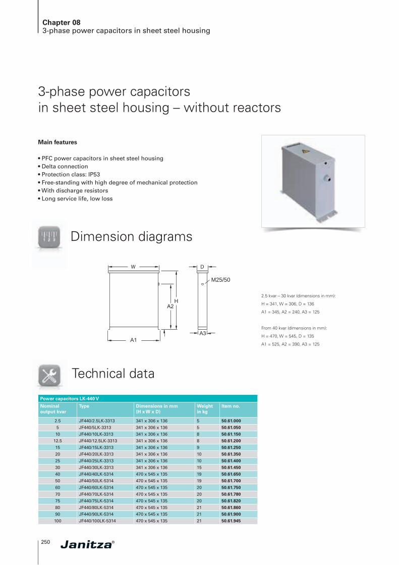
3-phase power capacitors in sheet steel housing – without reactors
Main features
• PFC power capacitors in sheet steel housing• Delta connection• Protection class: IP53• Free-standing with high degree of mechanical protection• With discharge resistors• Long service life, low loss
Dimension diagrams
M25/50
W D
2.5 kvar – 30 kvar (dimensions in mm):
H = 341, W = 306, D = 136
A1 = 345, A2 = 240, A3 = 125
From 40 kvar (dimensions in mm):
H = 470, W = 545, D = 135
A1 = 525, A2 = 390, A3 = 125
Power capacitors LK-440 V
Nominal output kvar
Type Dimensions in mm (H x W x D)
Weight in kg
Item no.
2.5 JF440/2.5LK-3313 341 x 306 x 136 5 50.61.000
5 JF440/5LK-3313 341 x 306 x 136 5 50.61.050
10 JF440/10LK-3313 341 x 306 x 136 8 50.61.150
12.5 JF440/12.5LK-3313 341 x 306 x 136 8 50.61.200
15 JF440/15LK-3313 341 x 306 x 136 9 50.61.250
20 JF440/20LK-3313 341 x 306 x 136 10 50.61.350
25 JF440/25LK-3313 341 x 306 x 136 10 50.61.400
30 JF440/30LK-3313 341 x 306 x 136 15 50.61.450
40 JF440/40LK-5314 470 x 545 x 135 19 50.61.650
50 JF440/50LK-5314 470 x 545 x 135 19 50.61.700
60 JF440/60LK-5314 470 x 545 x 135 20 50.61.750
70 JF440/70LK-5314 470 x 545 x 135 20 50.61.780
75 JF440/75LK-5314 470 x 545 x 135 20 50.61.820
80 JF440/80LK-5314 470 x 545 x 135 21 50.61.860
90 JF440/90LK-5314 470 x 545 x 135 21 50.61.900
100 JF440/100LK-5314 470 x 545 x 135 21 50.61.945
Technical data
08
251
Chapter 08De-tuned 3-phase power capacitors in sheet steel cabinet
Dimension diagrams
W D
W D
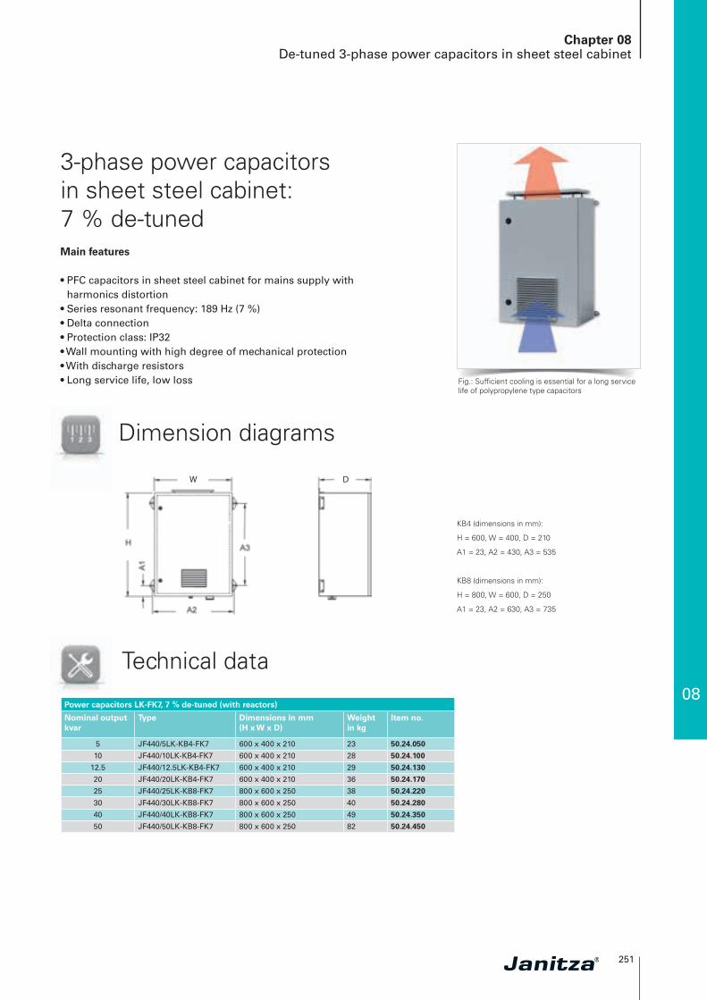
KB4 (dimensions in mm):
H = 600, W = 400, D = 210
A1 = 23, A2 = 430, A3 = 535
KB8 (dimensions in mm):
H = 800, W = 600, D = 250
A1 = 23, A2 = 630, A3 = 735
3-phase power capacitors in sheet steel cabinet: 7 % de-tuned Main features
• PFC capacitors in sheet steel cabinet for mains supply with harmonics distortion
• Series resonant frequency: 189 Hz (7 %)• Delta connection• Protection class: IP32• Wall mounting with high degree of mechanical protection• With discharge resistors• Long service life, low loss
Technical data
Fig.: Sufficient cooling is essential for a long service life of polypropylene type capacitors
Power capacitors LK-FK7, 7 % de-tuned (with reactors)
Nominal output kvar
Type Dimensions in mm (H x W x D)
Weight in kg
Item no.
5 JF440/5LK-KB4-FK7 600 x 400 x 210 23 50.24.050
10 JF440/10LK-KB4-FK7 600 x 400 x 210 28 50.24.100
12.5 JF440/12.5LK-KB4-FK7 600 x 400 x 210 29 50.24.130
20 JF440/20LK-KB4-FK7 600 x 400 x 210 36 50.24.170
25 JF440/25LK-KB8-FK7 800 x 600 x 250 38 50.24.220
30 JF440/30LK-KB8-FK7 800 x 600 x 250 40 50.24.280
40 JF440/40LK-KB8-FK7 800 x 600 x 250 49 50.24.350
50 JF440/50LK-KB8-FK7 800 x 600 x 250 82 50.24.450
252
Chapter 08De-tuned 3-phase power capacitors in sheet steel cabinet
Dimension diagrams
W D
W D
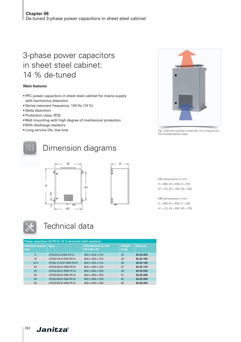
KB4 (dimensions in mm):
H = 600, W = 400, D = 210
A1 = 23, A2 = 430, A3 = 535
KB8 (dimensions in mm):
H = 800, W = 600, D = 250
A1 = 23, A2 = 630, A3 = 735
3-phase power capacitors in sheet steel cabinet: 14 % de-tunedMain features
• PFC power capacitors in sheet steel cabinet for mains supply with harmonics distortion
• Series resonant frequency: 134 Hz (14 %)• Delta distortion• Protection class: IP32• Wall mounting with high degree of mechanical protection• With discharge resistors• Long service life, low loss
Technical data
Power capacitors LK-FK14, 14 % de-tuned (with reactors)
Nominal output kvar
Type Dimensions in mm(H x W x D)
Weight in kg
Item no.
5 JF525/5LK-KB4-FK14 600 x 400 x 210 24 50.25.050
10 JF525/10LK-KB4-FK14 600 x 400 x 210 29 50.25.100
12.5 JF525/12.5LK-KB4-FK14 600 x 400 x 210 30 50.25.130
20 JF525/20LK-KB8-FK14 600 x 400 x 210 37 50.25.170
25 JF525/25LK-KB8-FK14 800 x 600 x 250 39 50.25.220
30 JF525/30LK-KB8-FK14 800 x 600 x 250 51 50.25.280
40 JF525/40LK-KB8-FK14 800 x 600 x 250 63 50.25.350
50 JF525/50LK-KB8-FK14 800 x 600 x 250 83 50.25.450
Fig.: Sufficient cooling is essential for a long service life of polypropylene type

08
253
Chapter 08Automatic power factor correction systems without reactors
Automatic power factor correction systems without reactors
Low loss
Long service life
High tolerance of start-up currents inrush current withstand capability• Optimised metal spraying process• Wave-cut film design• Capacitor contactors with pre-closing
contacts for inrush current d amping
High operational reliability• Capacitors with fivefold safety system• PFC controller with 8-way alarm
message• Heavy duty sheet steel cabinets• Optimised thermal design• Exclusive use of quality components
Long service life• Generous space- / power-ratio• Generously dimensioned cooling
system• High quality capacitors
Self-healing
Optimised,
thermal design
✔
254
Chapter 08Automatic power factor correction systems without reactors
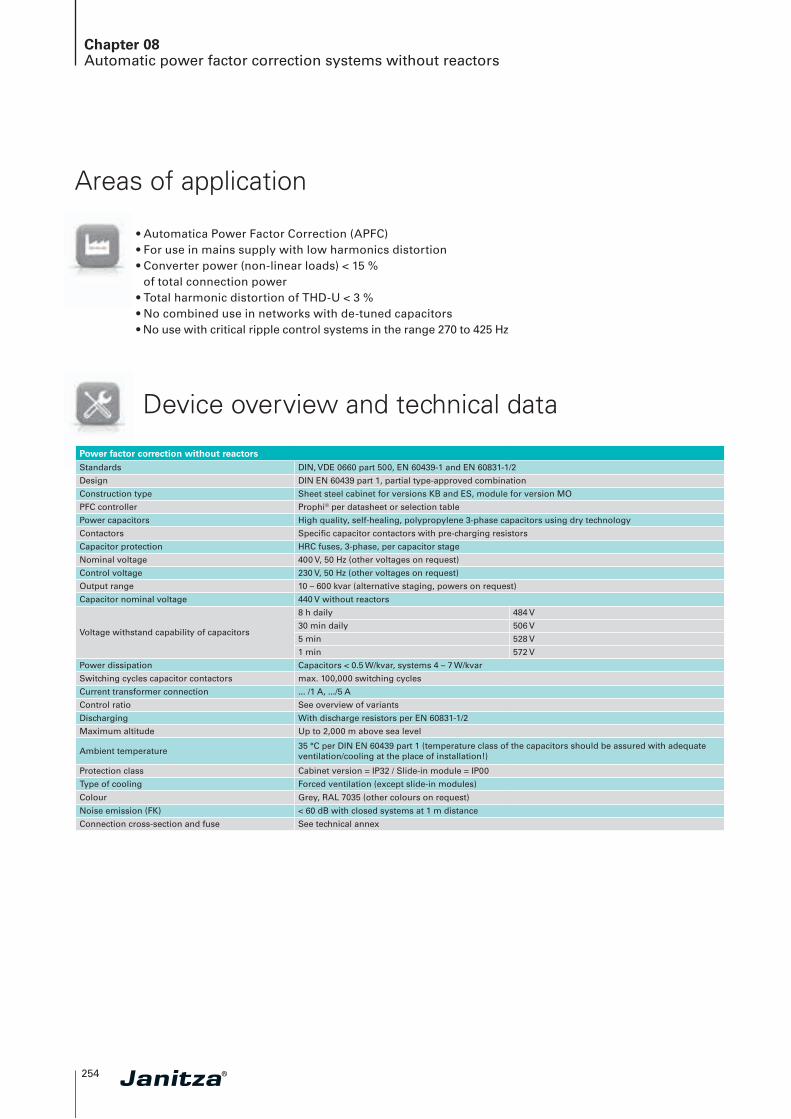
• Automatica Power Factor Correction (APFC)• For use in mains supply with low harmonics distortion• Converter power (non-linear loads) < 15 %
of total connection power• Total harmonic distortion of THD-U < 3 %• No combined use in networks with de-tuned capacitors• No use with critical ripple control systems in the range 270 to 425 Hz
Areas of application
Device overview and technical data
Power factor correction without reactorsStandards DIN, VDE 0660 part 500, EN 60439-1 and EN 60831-1/2
Design DIN EN 60439 part 1, partial type-approved combination
Construction type Sheet steel cabinet for versions KB and ES, module for version MO
PFC controller Prophi® per datasheet or selection table
Power capacitors High quality, self-healing, polypropylene 3-phase capacitors using dry technology
Contactors Specific capacitor contactors with pre-charging resistors
Capacitor protection HRC fuses, 3-phase, per capacitor stage
Nominal voltage 400 V, 50 Hz (other voltages on request)
Control voltage 230 V, 50 Hz (other voltages on request)
Output range 10 – 600 kvar (alternative staging, powers on request)
Capacitor nominal voltage 440 V without reactors
Voltage withstand capability of capacitors
8 h daily 484 V
30 min daily 506 V
5 min 528 V
1 min 572 V
Power dissipation Capacitors < 0.5 W/kvar, systems 4 – 7 W/kvar
Switching cycles capacitor contactors max. 100,000 switching cycles
Current transformer connection ... /1 A, .../5 A
Control ratio See overview of variants
Discharging With discharge resistors per EN 60831-1/2
Maximum altitude Up to 2,000 m above sea level
Ambient temperature35 °C per DIN EN 60439 part 1 (temperature class of the capacitors should be assured with adequate ventilation/cooling at the place of installation!)
Protection class Cabinet version = IP32 / Slide-in module = IP00
Type of cooling Forced ventilation (except slide-in modules)
Colour Grey, RAL 7035 (other colours on request)
Noise emission (FK) < 60 dB with closed systems at 1 m distance
Connection cross-section and fuse See technical annex
08
255
Chapter 08Automatic power factor correction systems without reactors
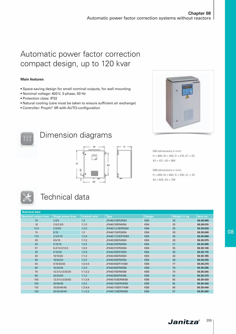
Automatic power factor correction compact design, up to 120 kvar
Main features
• Space-saving design for small nominal outputs, for wall mounting• Nominal voltage: 400 V, 3-phase, 50 Hz• Protection class: IP32• Natural cooling (care must be taken to ensure sufficient air exchange)• Controller: Prophi® 6R with AUTO-configuration
Technical data
KB4 (dimensions in mm):
H = 600, W = 400, D = 210, A1 = 23
A2 = 421, A3 = 560
KB8 (dimensions in mm):
H = 800, W = 600, D = 250, A1 = 23
A2 = 620, A3 = 756
Technical data
Nominal output kvar Stage power kvar Control ratio Type Design Weight in kg Item no.7.5 2.5/5 1:2 JF440/7.5ER3KB4 KB4 25 50.39.005
10 2.5/2.5/5 1:1:2 JF440/10ER4KB4 KB4 25 50.39.015
12.5 2.5/5/5 1:2:2 JF440/12.5ER5KB4 KB4 25 50.39.030
15 5/10 1:2 JF440/15ER3KB4 KB4 26 50.39.045
17.5 2.5/5/10 1:2:4 JF440/17.5/ER7KB4 KB4 26 50.39.060
20 5/5/10 1:1:2 JF440/20ER4KB4 KB4 29 50.39.075
25 5/10/10 1:2:2 JF440/25ER5KB4 KB4 27 50.39.095
31 6.2/12.5/12.5 1:2:2 JF440/31ER5KB4 KB4 35 50.39.145
35 5/10/20 1:2:4 JF440/35ER7KB4 KB4 35 50.39.175
40 10/10/20 1:1:2 JF440/40ER4KB4 KB4 36 50.39.195
50 10/20/20 1:2:2 JF440/50ER5KB4 KB4 38 50.39.235
55 5/10/20/20 1:2:4:4 JF440/55ER11KB8 KB8 77 50.39.270
60 10/20/30 1:2:3 JF440/60ER6KB8 KB8 78 50.39.295
75 12.5/12.5/25/25 1:1:2:2 JF440/75ER6KB8 KB8 70 50.39.345
80 20/20/40 1:1:2 JF440/80ER4KB8 KB8 92 50.39.370
100 12.5/12.5/25/50 1:1:2:4 JF440/100ER8KB8 KB8 95 50.39.420
100 20/40/40 1:2:2 JF440/100ER5KB8 KB8 95 50.39.430
110 10/20/40/40 1:2:4:4 JF440/110ER11KB8 KB8 96 50.39.440
120 20/20/40/40 1:1:2:2 JF440/120ER6KB8 KB8 97 50.39.450
Dimension diagrams
256
Chapter 08Automatic power factor correction systems without reactors
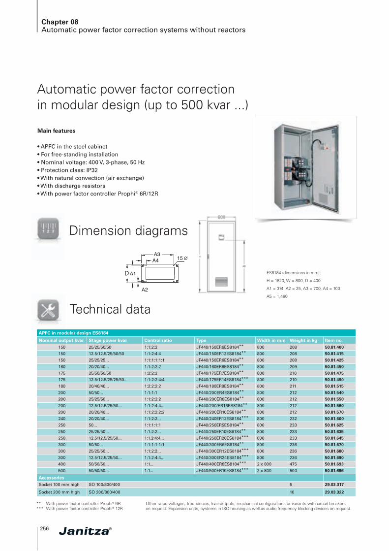
Automatic power factor correction in modular design (up to 500 kvar ...)
Main features
• APFC in the steel cabinet• For free-standing installation• Nominal voltage: 400 V, 3-phase, 50 Hz• Protection class: IP32• With natural convection (air exchange)• With discharge resistors• With power factor controller Prophi® 6R/12R
Dimension diagrams
Technical data
ES8184 (dimensions in mm):
H = 1820, W = 800, D = 400
A1 = 374, A2 = 25, A3 = 700, A4 = 100
A5 = 1,480
APFC in modular design ES8184
Nominal output kvar Stage power kvar Control ratio Type Width in mm Weight in kg Item no.150 25/25/50/50 1:1:2:2 JF440/150ER6ES8184** 800 208 50.81.400
150 12.5/12.5/25/50/50 1:1:2:4:4 JF440/150ER12ES8184** 800 208 50.81.415
150 25/25/25... 1:1:1:1:1:1 JF440/150ER6ES8184** 800 208 50.81.425
160 20/20/40... 1:1:2:2:2 JF440/160ER8ES8184** 800 209 50.81.450
175 25/50/50/50 1:2:2:2 JF440/175ER7ES8184** 800 210 50.81.475
175 12.5/12.5/25/25/50... 1:1:2:2:4:4 JF440/175ER14ES8184*** 800 210 50.81.490
180 20/40/40... 1:2:2:2:2 JF440/180ER9ES8184** 800 211 50.81.515
200 50/50... 1:1:1:1 JF440/200ER4ES8184** 800 212 50.81.540
200 25/25/50... 1:1:2:2:2 JF440/200ER8ES8184** 800 212 50.81.550
200 12.5/12.5/25/50... 1:1:2:4:4... JF440/200/ER16ES8184** 800 212 50.81.560
200 20/20/40... 1:1:2:2:2:2 JF440/200ER10ES8184** 800 212 50.81.570
240 20/20/40... 1:1:2:2... JF440/240ER12ES8184*** 800 232 50.81.600
250 50... 1:1:1:1:1 JF440/250ER5ES8184** 800 233 50.81.625
250 25/25/50... 1:1:2:2... JF440/250ER10ES8184** 800 233 50.81.635
250 12.5/12.5/25/50... 1:1.2:4:4... JF440/250ER20ES8184*** 800 233 50.81.645
300 50/50... 1:1:1:1:1:1 JF440/300ER6ES8184** 800 236 50.81.670
300 25/25/50... 1:1:2:2... JF440/300ER12ES8184*** 800 236 50.81.680
300 12.5/12.5/25/50... 1:1:2:4:4... JF440/300ER24ES8184*** 800 236 50.81.690
400 50/50/50... 1:1... JF440/400ER8ES8184*** 2 x 800 475 50.81.693
500 50/50/50... 1:1... JF440/500ER10ES8184*** 2 x 800 500 50.81.696
AccessoriesSocket 100 mm high SO 100/800/400 5 29.03.317
Socket 200 mm high SO 200/800/400 10 29.03.322
** With power factor controller Prophi® 6R *** With power factor controller Prophi® 12R
Other rated voltages, frequencies, kvar-outputs, mechanical configurations or variants with circuit breakers on request. Expansion units, systems in ISO housing as well as audio frequency blocking devices on request.
D
W
D
W
08
257
Chapter 08Automatic power factor correction systems without reactors
ES8184 (dimensions in mm):
H = 1820, W = 800, D = 400
A1 = 374, A2 = 25, A3 = 700, A4 = 100
A5 = 1,480
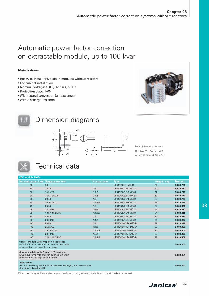
Automatic power factor correction on extractable module, up to 100 kvar
Main features
• Ready-to-install PFC slide-in modules without reactors• For cabinet installation• Nominal voltage: 400 V, 3-phase, 50 Hz• Protection class: IP00• With natural convection (air exchange)• With discharge resistors
Dimension diagrams
Technical data
MO84 (dimensions in mm):
H = 330, W = 703, D = 333
A1 = 290, A2 = 14, A3 = 26.5
PFC module M084
Nominal output kvar Stage power kvar Control ratio Type Weight in kg Item no.50 50 JF440/50EK1MO84 22 50.80.700
50 25/25 1:1 JF440/50/2EK2MO84 22 50.80.740
50 10/20/20 1:2:2 JF440/50/3EK5MO84 22 50.80.770
50 12.5/12.5/25 1:1:2 JF440/50/3/EK4MO84 22 50.80.774
60 20/40 1:2 JF440/60/2EK3MO84 23 50.80.775
60 10/10/20/20 1:1:2:2 JF440/60/4EK6MO84 23 50.80.776
75 25/50 1:2 JF440/75/2EK3MO84 24 50.80.800
75 25/25/25 1:1:1 JF440/75/3EK3MO84 24 50.80.810
75 12.5/12.5/25/25 1:1:2:2 JF440/75/4EK6MO84 24 50.80.811
80 40/40 1:1 JF440/80/2EK2MO84 24 50.80.835
80 20/20/40 1:1:2 JF440/80/3EK4MO84 24 50.80.837
100 50/50 1:1 JF440/100/2EK2MO84 25 50.80.875
100 25/25/50 1:1:2 JF440/100/3EK4MO84 25 50.80.880
100 25/25/25/25 1:1:1:1 JF440/100/4EK4MO84 25 50.80.900
100 20/40/40 1:2:2 JF440/100/3EK5MO84 25 50.80.902
100 12.5/12.5/25/50 1:1:2:4 JF440/100/4EK8MO84 25 50.80.903
Control module with Prophi® 6R controllerMCCB, CT terminals and 2 m connection cable(mounted on the capacitor module)
50.80.003
Control module with Prophi® 12R controllerMCCB, CT terminals and 2 m connection cable(mounted on the capacitor module)
50.80.004
AccessoriesSet module fixing rail for Rittal cabinets, left/right, with accessories(for Rittal cabinet MO84)
50.00.100
Other rated voltages, frequencies, ouputs, mechanical configurations or variants with circuit breakers on request.
258
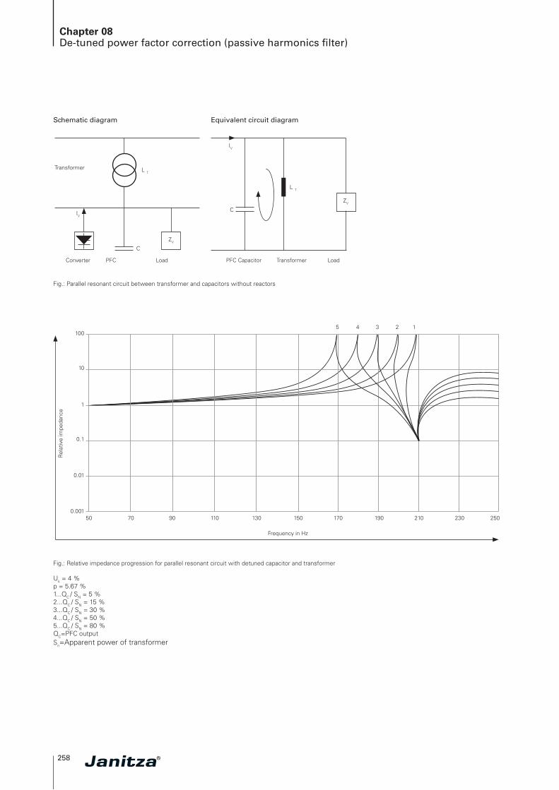
Chapter 08De-tuned power factor correction (passive harmonics filter)
Fig.: Parallel resonant circuit between transformer and capacitors without reactors
Fig.: Relative impedance progression for parallel resonant circuit with detuned capacitor and transformer
Uk = 4 %p = 5.67 %1...QC / SN = 5 %2...QC / SN = 15 %3...QC / SN = 30 %4...QC / SN = 50 %5...QC / SN = 80 %QC=PFC outputSn=Apparent power of transformer
5 4 3 2 1
500.001
0.01
0.1
1
10
100
Frequency in Hz
Rel
ativ
e im
peda
nce
70 90 110 130 150 170 190 210 230 250
Schematic diagram Equivalent circuit diagram
Transformer
Converter PFC Load LoadTransformerPFC Capacitor
IV
IV
L T
L T
ZV
ZV
C
C

08
259
Chapter 08Automatic de-tuned power factor correction systems
Automatic de-tuned power factor correction systems
Low loss
Long service life
Optimised filter design• Precise filter circuit frequency matching• High quality reactors• Temperature protection in the event
of overload• Filter circuit reactors with high
linearity and low loss
High operational reliability• Capacitors with fivefold safety• PFC controller with 8-way
alarm message• Optimised thermal design• Exclusive use of quality components
Long service life• Generous space- / power-ratio• Generously dimensioned cooling system• High quality capacitors and filter
circuit reactors with 100 % duty cycle
Optimised,
thermal design
De-tuned version
✔

260
Chapter 08Automatic de-tuned power factor correction systems
• Automatic power factor correction with reactors• For use in mains supply with harmonics distortion• Converter power (non-linear loads) > 15 %
of the connection power• Total harmonic distortion of THD-U > 3 %• To preveant cases of resonance• Harmonics filtering and improvement of power quality• Reduction in reactive energy costs and PFC penalties
Areas of application
Device overview and technical dataDe-tuned power factor correction
Technical dataStandards DIN, VDE 0660 part 500, EN 60439-1 and EN 60831-1/2
Design in accordance with DIN EN 60439 part 1, partial type-approved combination
Construction type Sheet steel cabinet for versions KB and ES, module for version MO
Dynamic PFC controller Prophi® per datasheet or selection table
Power capacitors High quality, self-healing, polypropylene 3-phase capacitors using dry technology
Filter circuit reactors Low-loss 3-phase reactors with high linearity, 7%, 14% (other ratings on request), with 100% duty cycle
Contactors Specific capacitor contactors
Capacitor protection HRC fuses, 3-phase, per capacitor stage
Nominal voltage 400 V, 50 Hz (other voltages on request)
Control voltage 230 V, 50 Hz (other voltages on request)
Output range 10 – 600 kvar (alternative staging, outputs on request)
Capacitor nominal voltage 440 V with 5.67 – 7 % (detuned), 525 V with 14 % (detuned)
Voltage withstand capability of capacitors
At p = 5.67 – 7 % 440 V At p = 14 % 525 V
8 h daily 484 V 577 V
30 min daily 506 V 604 V
5 min 528 V 630 V
1 min 572 V 682 V
Power dissipation Capacitors < 0.5 W/kvar, systems 4 – 7 W/kvar
System designPermissible harmonics
currentsHarmonics voltage
I 250 Hz I 350 Hz U 250 Hz U 350 Hz
FK 5.67 0.565 IN 0.186 IN 5 % 5 %
FK 7 0.31 IN 0.134 IN 5 % 5 %
FK 14 0.086 IN 0.051 IN 5 % 5 %
Switching cycles capacitor contactors max. 100,000 switching cycles
Current transformer connection ... /1 A, .../5 A
Control ratio See overview of variants
Discharging With discharge resistors per EN 60831-1/2
Maximum altitude Up to 2,000 m above sea level
Ambient temperature35 °C per DIN EN 60439 part 1 (temperature class of the capacitors should be assured with adequate ventilation/cooling at the place of installation!)
Protection class Cabinet version = IP32 / Slide-in module = IP00
Type of cooling Forced ventilation (except slide-in modules)
Colour Grey, RAL 7035 (other colours on request)
Noise emission (FK) < 60 dB with closed systems at 1 m distance
Connection cross-section and fuse See technical annex
The following reactors can be used in mains supply with ripple control systems:
Ripple control frequency De-tuning factor Filter series resonant frequency< 168 Hz p = 14 % fr = 134 Hz
168 – 183 Hz p = 14 / 5.67 % fr = 134 / 210 Hz
> = 216.67 p = 8 % fr = 177 Hz
> 228 Hz p = 7 % fr = 189 Hz
> 350 Hz p = 5.67 % fr = 210 Hz

08
261
Chapter 08Automatic de-tuned power factor correction systems
Automatic de-tuned power factor correction (Harmonics filter), compact design
Main features
• APFC in the steel cabinet• For wall mounting• Nominal voltage: 400 V, 3-phase, 50 Hz• Reactors: 7 % and 14 %• Protection class: IP32• Ventilation: From 31 kvar with fan in the cabinet door for forced cooling• With discharge resistors• With power factor controller Prophi® 6R
Dimension diagrams Technical data
W
KB6825 (dimensions in mm):
W = 600, H = 800, D = 250, A1 = 410
KB6123 (dimensions in mm):
W = 600, H = 1,200, D = 300, A1 = 655
7 % de-tuned in accordance with series resonant frequency 189 Hz
Nominal outputkvar
Stagepower kvar
Control ratio
Type Design Weight in kg
Item no.
15 5/10 1:2 JF440/15ER3KB6825FK7 KB6825 112 50.52.020
20 5/5/10 1:1:2 JF440/20ER4KB6825FK7 KB6825 113 50.52.040
25 5/10/10 1:2:2 JF440/25ER5KB6825FK7 KB6825 116 50.52.080
31 6.25/12.5/12.5 1:2:2 JF440/31/ER5KB6825FK7 KB6825 118 50.52.110
35 5/10/20 1:2:4 JF440/35ER7KB6825FK7 KB6825 122 50.52.150
43.75 6.25/12.5/25 1:2:4 JF440/43.75ER7KB6825FK7 KB6825 138 50.52.180
50 10/20/20 1:2:2 JF440/50ER5KB6825FK7 KB6825 142 50.52.210
60 10/20/30 1:2:3 JF440/60ER6KB6123FK7 KB6123 158 50.52.225
75 12.5/25/37.5 1:2:3 JF440/75ER6KB6123FK7 KB6123 167 50.52.240
14 % de-tuned in accordance with series resonant frequency 134 Hz
Nominal outputkvar
Stagepower kvar
Control ratio
Type Design Weight in kg
Item no.
15 5/10 1:2 JF525/15ER3KB6825FK14 KB6825 123 50.52.520
20 5/5/10 1:1:2 JF525/20ER4KB6825FK14 KB6825 124 50.52.540
25 5/10/10 1:2:2 JF525/25ER5KB6825FK14 KB6825 128 50.52.580
31 6.25/12.5/12.5 1:2:2 JF525/31/ER5KB6825FK14 KB6825 130 50.52.610
35 5/10/20 1:2:4 JF525/35ER7KB6825FK14 KB6825 134 50.52.650
43.75 6.25/12.5/25 1:2:4 JF525/43.75ER7KB6825FK14 KB6825 152 50.52.680
50 10/20/20 1:2:2 JF525/50ER5KB6825FK14 KB6825 173 50.52.710
60 10/20/30 1:2:3 JF525/60ER6KB6123FK14 KB6123 184 50.52.725
75 12.5/25/37.5 1:2:3 JF525/75ER6KB6123FK14 KB6123 195 50.52.729
Other rated voltages, frequencies, outputs, reactors, mechanical configurations or variants with circuit breakers on request.
Other rated voltages, frequencies, outputs, reactors, mechanical configurations or variants with circuit breakers on request.

262
Chapter 08Automatic de-tuned power factor correction systems
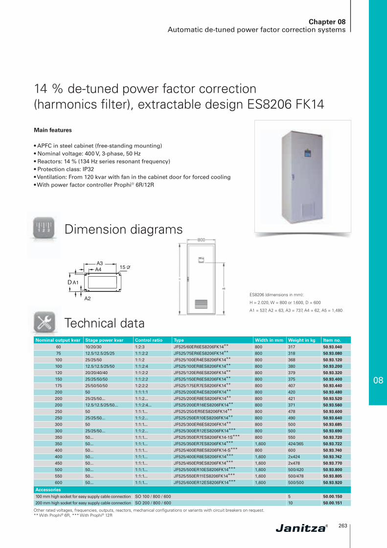
7 % de-tuned power factor correction (harmonics filter), extractable design ES8206 FK7
Main features
• APFC in steel cabinet (free-standing mounting)• Nominal voltage: 400 V, 3-phase, 50 Hz• Reactor: 7 % (189 Hz series resonant frequency)• Protection class: IP32• Ventilation: From 120 kvar with fan in the cabinet door for forced cooling• With power factor controller Prophi® 6R/12R
Technical dataNominal output kvar Stage power kvar Control ratio Type Width in mm Weight in kg Item no.
60 10/20/30 1:2:3... JF440/60ER6ES8206FK7** 800 278 50.89.040
75 12.5/12.5/25... 1:1:2... JF440/75ER6ES8206FK7** 800 278 50.89.080
100 25/25/50 1:1:2 JF440/100ER4ES8206FK7** 800 288 50.89.120
100 12.5/12.5/25/50 1:1:2:4 JF440/100ER8ES8206FK7** 800 288 50.89.200
120 20/20/40/40 1:1:2:2 JF440/120ER6ES8206FK7** 800 340 50.89.320
150 25/25/50/50 1:1:2:2 JF440/150ER6ES8206FK7** 800 344 50.89.400
175 25/50/50/50 1:2:2:2 JF440/175ER7ES8206FK7** 800 367 50.89.440
200 50... 1:1:1... JF440/200ER4ES8206FK7** 800 314 50.89.480
200 25/25/50... 1:1:2... JF440/200ER8ES8206FK7** 800 314 50.89.520
200 12.5/12.5/25/50... 1:1:2:4.. JF440/200ER16ES8206FK7** 800 314 50.89.560
250 50... 1:1:1... JF440/250/ER5ES8206FK7** 800 437 50.89.600
250 25/25/50... 1:1:2... JF440/250ER10ES8206FK7** 800 437 50.89.640
300 50... 1:1:1... JF440/300ER6ES8206FK7** 800 487 50.89.685
300 25/25/50... 1:1:2... JF440/300ER12ES8206FK7*** 800 498 50.89.687
350 50... 1:1:1... JF440/350ER7ES8206FK7-1S*** 800 520 50.89.720
350 50... 1:1:1... JF440/350ER7ES8206FK7*** 1,600 352/347 50.89.722
400 50... 1:1:1... JF440/400ER8ES8206FK7-1S*** 800 570 50.89.744
400 50... 1:1.1... JF440/400ER8ES8206FK7*** 1,600 2x370 50.89.740
450 50... 1:1:1... JF440/450ER9ES8206FK7*** 1,600 437/347 50.89.770
500 50... 1:1:1... JF440/500ER10ES8206FK7*** 1,600 479/359 50.89.800
550 50... 1:1:1... JF440/550ER11ES8206FK7*** 1,600 2x431 50.89.805
600 50... 1:1:1... JF440/600ER12ES8206FK7*** 1,600 2x481 50.89.820
Accessories100 mm high socket for easy supply cable connection SO 100 / 800 / 600 5 50.00.150
200 mm high socket for easy supply cable connection SO 200 / 800 / 600 10 50.00.151
D
W
D
W
ES8206 (dimensions in mm):
H = 2.020, W = 800 or 1.600, D = 600
A1 = 537, A2 = 63, A3 = 737, A4 = 62, A5 = 1,480
Other rated voltages, frequencies, outputs, reactors, mechanical configurations or variants with circuit breakers on request. ** With Prophi® 6R, *** With Prophi® 12R
Dimension diagrams
08
263
Chapter 08Automatic de-tuned power factor correction systems
14 % de-tuned power factor correction (harmonics filter), extractable design ES8206 FK14
Main features
• APFC in steel cabinet (free-standing mounting)• Nominal voltage: 400 V, 3-phase, 50 Hz• Reactors: 14 % (134 Hz series resonant frequency)• Protection class: IP32• Ventilation: From 120 kvar with fan in the cabinet door for forced cooling• With power factor controller Prophi® 6R/12R
Technical data
D
W
D
W
ES8206 (dimensions in mm):
H = 2.020, W = 800 or 1.600, D = 600
A1 = 537, A2 = 63, A3 = 737, A4 = 62, A5 = 1,480
Nominal output kvar Stage power kvar Control ratio Type Width in mm Weight in kg Item no.60 10/20/30 1:2:3 JF525/60ER6ES8206FK14** 800 317 50.93.040
75 12.5/12.5/25/25 1:1:2:2 JF525/75ER6ES8206FK14** 800 318 50.93.080
100 25/25/50 1:1:2 JF525/100ER4ES8206FK14** 800 368 50.93.120
100 12.5/12.5/25/50 1:1:2:4 JF525/100ER8ES8206FK14** 800 380 50.93.200
120 20/20/40/40 1:1:2:2 JF525/120ER6ES8206FK14** 800 379 50.93.320
150 25/25/50/50 1:1:2:2 JF525/150ER6ES8206FK14** 800 375 50.93.400
175 25/50/50/50 1:2:2:2 JF525/175ER7ES8206FK14** 800 407 50.93.440
200 50 1:1:1:1 JF525/200ER4ES8206FK14** 800 420 50.93.480
200 25/25/50... 1:1:2... JF525/200ER8ES8206FK14** 800 421 50.93.520
200 12.5/12.5/25/50... 1:1:2:4... JF525/200ER16ES8206FK14** 800 371 50.93.560
250 50 1:1:1... JF525/250/ER5ES8206FK14** 800 478 50.93.600
250 25/25/50... 1:1:2... JF525/250ER10ES8206FK14** 800 490 50.93.640
300 50 1:1:1... JF525/300ER6ES8206FK14** 800 500 50.93.685
300 25/25/50... 1:1:2... JF525/300ER12ES8206FK14*** 800 500 50.93.690
350 50... 1:1:1... JF525/350ER7ES8206FK14-1S*** 800 550 50.93.720
350 50... 1:1:1... JF525/350ER7ES8206FK14*** 1,600 424/365 50.93.722
400 50... 1:1:1... JF525/400ER8ES8206FK14-S*** 800 600 50.93.740
400 50... 1:1:1... JF525/400ER8ES8206FK14*** 1,600 2x424 50.93.742
450 50... 1:1:1... JF525/450ER9ES8206FK14*** 1,600 2x478 50.93.770
500 50... 1:1:1... JF525/500ER10ES8206FK14*** 1,600 500/420 50.93.800
550 50... 1:1:1... JF525/550ER11ES8206FK14*** 1,600 500/478 50.93.805
600 50... 1:1:1... JF525/600ER12ES8206FK14*** 1,600 500/500 50.93.920
Accessories100 mm high socket for easy supply cable connection SO 100 / 800 / 600 5 50.00.150
200 mm high socket for easy supply cable connection SO 200 / 800 / 600 10 50.00.151
Other rated voltages, frequencies, outputs, reactors, mechanical configurations or variants with circuit breakers on request. ** With Prophi® 6R, *** With Prophi® 12R
Dimension diagrams

264
Chapter 08De-tuned capacitor modules
De-tuned capacitor modules,extractable design
Main features
• Ready-to-install, de-tuned PFC slide-in modules• Completely mounted and wired with capacitors, reactors, contactors
and HRC-fuses• For slide-in installation in existing PFC or switchgear cabinets• Nominal voltage: 400 V, 3-phase, 50 Hz• Reactors: 7 % (189 Hz) and 14 % (134 Hz)• Protection class: IP32• Ventilation: Natural (care must be taken to ensure sufficient ventilation)• With discharge resistors
Dimension diagrams
Dimensions in mm:
H = 330, W = 703, D = 533
A1 = 290, A2 = 14, A3 = 26.5
08
265
Technical data
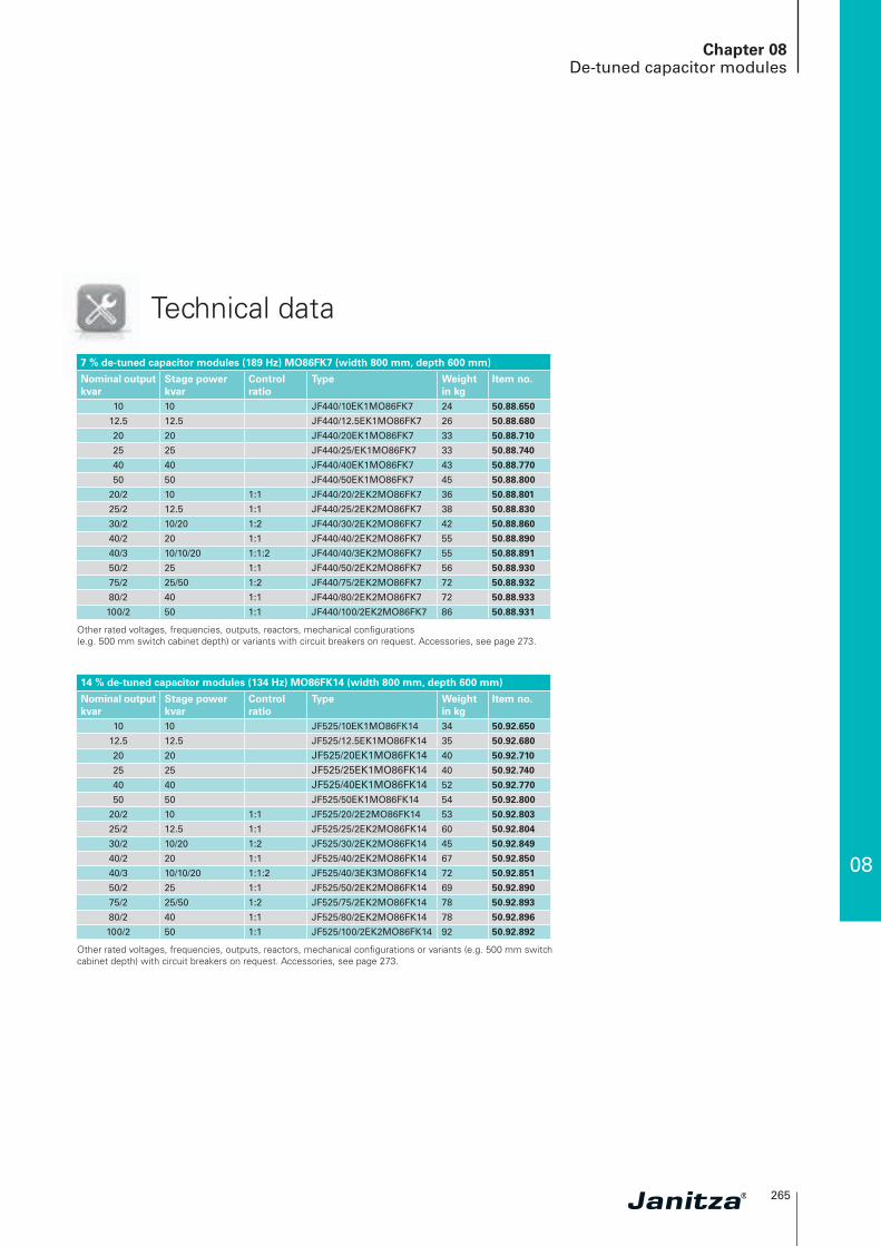
7 % de-tuned capacitor modules (189 Hz) MO86FK7 (width 800 mm, depth 600 mm)
Nominal outputkvar
Stage power kvar
Control ratio
Type Weight in kg
Item no.
10 10 JF440/10EK1MO86FK7 24 50.88.650
12.5 12.5 JF440/12.5EK1MO86FK7 26 50.88.680
20 20 JF440/20EK1MO86FK7 33 50.88.710
25 25 JF440/25/EK1MO86FK7 33 50.88.740
40 40 JF440/40EK1MO86FK7 43 50.88.770
50 50 JF440/50EK1MO86FK7 45 50.88.800
20/2 10 1:1 JF440/20/2EK2MO86FK7 36 50.88.801
25/2 12.5 1:1 JF440/25/2EK2MO86FK7 38 50.88.830
30/2 10/20 1:2 JF440/30/2EK2MO86FK7 42 50.88.860
40/2 20 1:1 JF440/40/2EK2MO86FK7 55 50.88.890
40/3 10/10/20 1:1:2 JF440/40/3EK2MO86FK7 55 50.88.891
50/2 25 1:1 JF440/50/2EK2MO86FK7 56 50.88.930
75/2 25/50 1:2 JF440/75/2EK2MO86FK7 72 50.88.932
80/2 40 1:1 JF440/80/2EK2MO86FK7 72 50.88.933
100/2 50 1:1 JF440/100/2EK2MO86FK7 86 50.88.931
14 % de-tuned capacitor modules (134 Hz) MO86FK14 (width 800 mm, depth 600 mm)
Nominal outputkvar
Stage power kvar
Control ratio
Type Weight in kg
Item no.
10 10 JF525/10EK1MO86FK14 34 50.92.650
12.5 12.5 JF525/12.5EK1MO86FK14 35 50.92.680
20 20 JF525/20EK1MO86FK14 40 50.92.710
25 25 JF525/25EK1MO86FK14 40 50.92.740
40 40 JF525/40EK1MO86FK14 52 50.92.770
50 50 JF525/50EK1MO86FK14 54 50.92.800
20/2 10 1:1 JF525/20/2E2MO86FK14 53 50.92.803
25/2 12.5 1:1 JF525/25/2EK2MO86FK14 60 50.92.804
30/2 10/20 1:2 JF525/30/2EK2MO86FK14 45 50.92.849
40/2 20 1:1 JF525/40/2EK2MO86FK14 67 50.92.850
40/3 10/10/20 1:1:2 JF525/40/3EK3MO86FK14 72 50.92.851
50/2 25 1:1 JF525/50/2EK2MO86FK14 69 50.92.890
75/2 25/50 1:2 JF525/75/2EK2MO86FK14 78 50.92.893
80/2 40 1:1 JF525/80/2EK2MO86FK14 78 50.92.896
100/2 50 1:1 JF525/100/2EK2MO86FK14 92 50.92.892
Other rated voltages, frequencies, outputs, reactors, mechanical configurations (e.g. 500 mm switch cabinet depth) or variants with circuit breakers on request. Accessories, see page 273.
Other rated voltages, frequencies, outputs, reactors, mechanical configurations or variants (e.g. 500 mm switch cabinet depth) with circuit breakers on request. Accessories, see page 273.
Chapter 08De-tuned capacitor modules
266
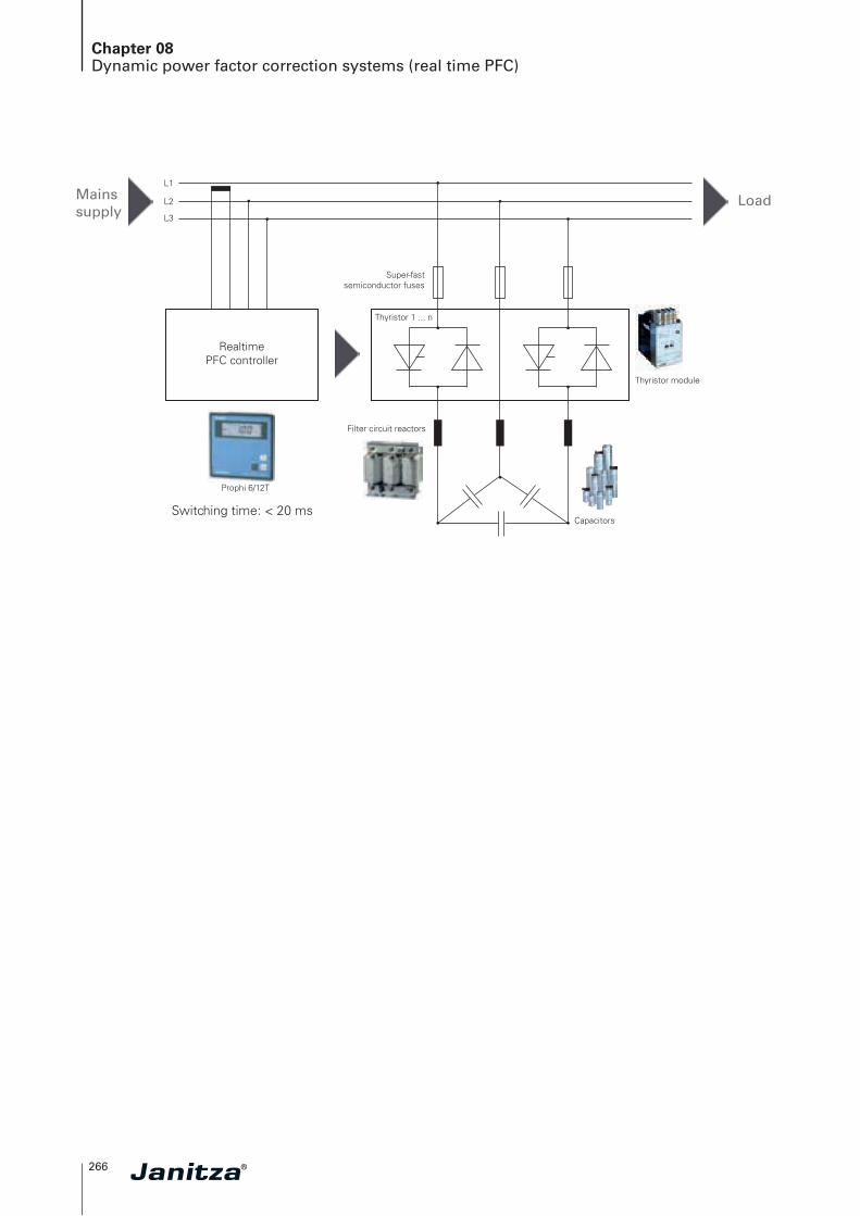
Chapter 08Dynamic power factor correction systems (real time PFC)
L1
L2
L3
Mains supply
Load
Realtime PFC controller
Thyristor 1 ... n
Prophi 6/12T
Filter circuit reactors
Capacitors
Thyristor module
Super-fast semiconductor fuses
Switching time: < 20 ms
08
267
Chapter 08Dynamic power factor correction systems (real time PFC)
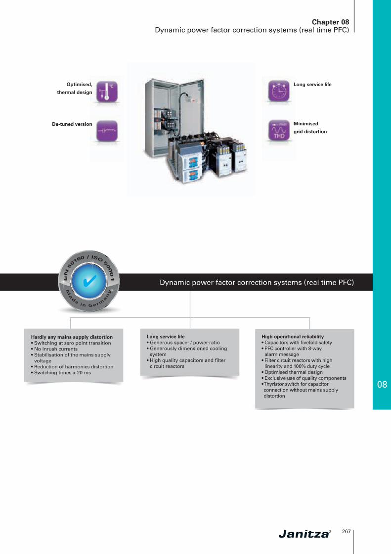
Dynamic power factor correction systems (real time PFC)
Hardly any mains supply distortion• Switching at zero point transition• No inrush currents• Stabilisation of the mains supply
voltage• Reduction of harmonics distortion• Switching times < 20 ms
Long service life• Generous space- / power-ratio• Generously dimensioned cooling
system• High quality capacitors and filter
circuit reactors
High operational reliability• Capacitors with fivefold safety• PFC controller with 8-way
alarm message• Filter circuit reactors with high
linearity and 100% duty cycle• Optimised thermal design• Exclusive use of quality components• Thyristor switch for capacitor connection without mains supply distortion
Long service life
Minimised
grid distortion
Optimised,
thermal design
De-tuned version
✔

268
Chapter 08Dynamic power factor correction systems (real time PFC)
Areas of application
Typical applications
• Automotive industry (welding systems, presses, etc.)• Lift systems and cranes• Start-up compensation for large motors• Drilling rigs in oil production• Wind turbines• Welding technology• Steel production• Plastic injection moulding systems• Fishing vessels
Particular advantages
• Improved power quality, i.e. avoidance of high start-up currents for the power capacitors
• Significant extending the service life for the PFC system • Safety of the complete system is significantly increased
(i.e. avoidance of damages through defective contactors and subsequent exploding capacitors)
• Ultra-fast compensation of power factor, resulting in a reduction in the reactive current costs and kWh losses
• Voltage stabilisation (e.g. contactors support during the start-up phase of large motors)
• Improved utilisation of the energy distribution (transformers, cabling, switchgear, etc.) through the elimination of power peaks
• Shortening of process times (e.g. welding) due to stabilized voltage
• Use in applications with fast and high load changes• APFC in LVDB• For use in mains supply with harmonics burden• Converter power (non-linear loads) > 15 %
of the connection power• Total harmonic distortion of THD-U > 3 %• Harmonics filtering and improvement of power quality• Reduction in reactive current costs• Stabilisation of the mains supply voltage
Fig.: Current reduction by means of dynamic PFC
Fig.: Comparison of current and voltage with and without dynamic PFC when starting up a large motor
With dynamic PFC
With dynamic PFC
Volt
age
Without dynamic PFC
Without dynamic PFC
Control signal
Current without dynamic PFC
With dynamic PFC
in sec
I in A
Cu
rren
t

08
269
Chapter 08Dynamic power factor correction systems (real time PFC)
Dynamic power factor correction
Technical dataStandards DIN, VDE 0660 part 500, EN 60439-1 and EN 60831-1/2
Design in accordance with DIN EN 60439 part 1, partial type-approved combination
Construction type Sheet steel cabinet for versions KB and ES, module for version MO
Dynamic power factor controller Prophi® T version per datasheet or selection table
Power capacitors High quality, self-healing, polypropylene 3-phase capacitors using dry technology
Filter circuit reactors Low-loss 3-phase reactors with high linearity, 7%, 14% (other reactor ratings on request)
Electronic switch (t < 20 ms) Thyristor actuator for switching in the zero point transition (to avoid network disturbances)
Capacitor protection Ultra-fast electronic fuses
Nominal voltage 400 V, 50 Hz (other voltages on request)
Control voltage 230 V, 50 Hz (other voltages on request)
Output range 10 – 600 kvar (alternative staging, outputs on request)
Capacitor nominal voltage 440 V with out reactors and 5.67 – 7 % (choked), 525 V with 14 % (reactors)
Voltage withstand capability of capacitors
At p = 5.67 – 7 % 440 V At p = 14 % 525 V
8 h daily 484 V 577 V
30 min daily 506 V 604 V
5 min 528 V 630 V
1 min 572 V 682 V
Power dissipation Capacitors < 0.5 W/kvar, systems 4 – 7 W/kvar
System designPermissible harmonics
currentsHarmonics voltage
I 250 Hz I 350 Hz U 250 Hz U 350 Hz
FK 5.67 0.565 IN 0.186 IN 5 % 5 %
FK 7 0.31 IN 0.134 IN 5 % 5 %
FK 14 0.086 IN 0.051 IN 5 % 5 %
Current transformer connection ... /1 A, .../5 A
Control ratio See overview of variants
Discharging With discharge resistors per EN 60831-1/2
Maximum altitude Up to 2,000 m above sea level
Ambient temperature35 °C per DIN EN 60439 part 1 (temperature class of the capacitors should be assured with adequate ventilation/cooling at the place of installation!)
Protection class Cabinet version = IP32 / Slide-in module = IP00
Type of cooling Forced ventilation (except slide-in modules)
Colour Grey, RAL 7035
Noise emission (FK) < 60 dB with closed systems at 1 m distance
Connection cross-section and fuse See technical annex
Device overview and technical data
The following reactors can be used in mains supply with ripple control systems:
Mains supply ripple control frequency De-tuning factor Filter series resonant frequency< 168 Hz p = 14 % fr = 134 Hz
168 – 183 Hz p = 14 / 5.67 % fr = 134 / 210 Hz
> = 216.67 p = 8 % fr = 177 Hz
> 228 Hz p = 7 % fr = 189 Hz
> 350 Hz p = 5.67 % fr = 210 Hz
270
Chapter 08De-tuned, dynamic power factor correction systems (real time PFC)
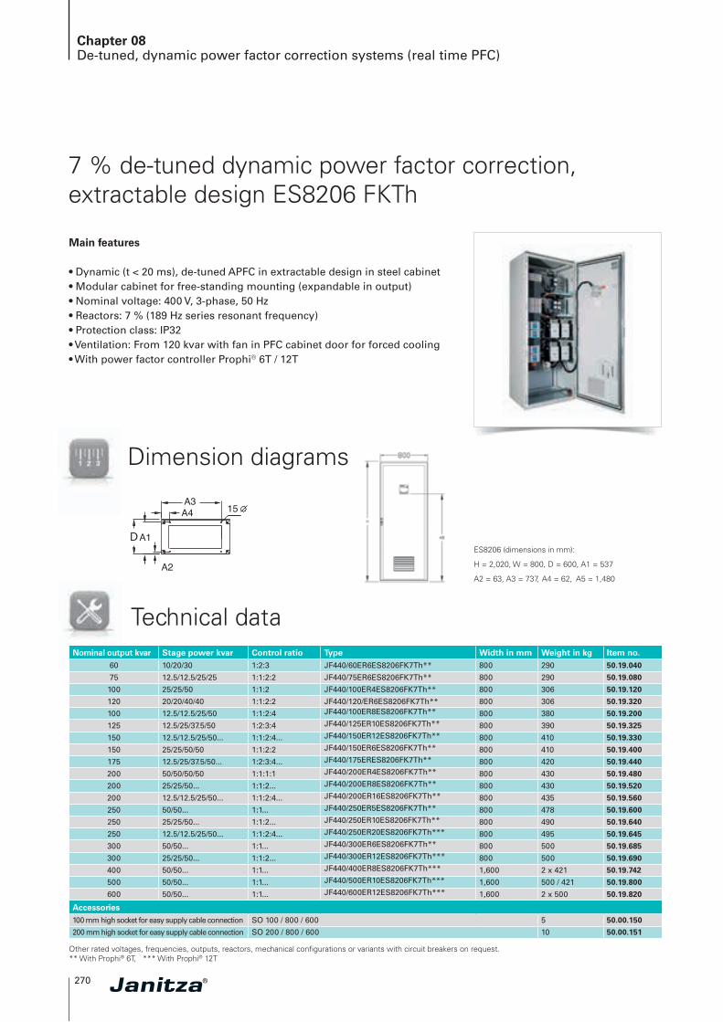
7 % de-tuned dynamic power factor correction, extractable design ES8206 FKTh
Main features
• Dynamic (t < 20 ms), de-tuned APFC in extractable design in steel cabinet• Modular cabinet for free-standing mounting (expandable in output)• Nominal voltage: 400 V, 3-phase, 50 Hz• Reactors: 7 % (189 Hz series resonant frequency)• Protection class: IP32• Ventilation: From 120 kvar with fan in PFC cabinet door for forced cooling• With power factor controller Prophi® 6T / 12T
Technical data
D
W
D
W
ES8206 (dimensions in mm):
H = 2,020, W = 800, D = 600, A1 = 537
A2 = 63, A3 = 737, A4 = 62, A5 = 1,480
Nominal output kvar Stage power kvar Control ratio Type Width in mm Weight in kg Item no.60 10/20/30 1:2:3 JF440/60ER6ES8206FK7Th** 800 290 50.19.040
75 12.5/12.5/25/25 1:1:2:2 JF440/75ER6ES8206FK7Th** 800 290 50.19.080
100 25/25/50 1:1:2 JF440/100ER4ES8206FK7Th** 800 306 50.19.120
120 20/20/40/40 1:1:2:2 JF440/120/ER6ES8206FK7Th** 800 306 50.19.320
100 12.5/12.5/25/50 1:1:2:4 JF440/100ER8ES8206FK7Th** 800 380 50.19.200
125 12.5/25/37.5/50 1:2:3:4 JF440/125ER10ES8206FK7Th** 800 390 50.19.325
150 12.5/12.5/25/50... 1:1:2:4... JF440/150ER12ES8206FK7Th** 800 410 50.19.330
150 25/25/50/50 1:1:2:2 JF440/150ER6ES8206FK7Th** 800 410 50.19.400
175 12.5/25/37.5/50... 1:2:3:4... JF440/175ERES8206FK7Th** 800 420 50.19.440
200 50/50/50/50 1:1:1:1 JF440/200ER4ES8206FK7Th** 800 430 50.19.480
200 25/25/50... 1:1:2... JF440/200ER8ES8206FK7Th** 800 430 50.19.520
200 12.5/12.5/25/50... 1:1:2:4... JF440/200ER16ES8206FK7Th** 800 435 50.19.560
250 50/50... 1:1... JF440/250ER5ES8206FK7Th** 800 478 50.19.600
250 25/25/50... 1:1:2... JF440/250ER10ES8206FK7Th** 800 490 50.19.640
250 12.5/12.5/25/50... 1:1:2:4... JF440/250ER20ES8206FK7Th*** 800 495 50.19.645
300 50/50... 1:1... JF440/300ER6ES8206FK7Th** 800 500 50.19.685
300 25/25/50... 1:1:2... JF440/300ER12ES8206FK7Th*** 800 500 50.19.690
400 50/50... 1:1... JF440/400ER8ES8206FK7Th*** 1,600 2 x 421 50.19.742
500 50/50... 1:1... JF440/500ER10ES8206FK7Th*** 1,600 500 / 421 50.19.800
600 50/50... 1:1... JF440/600ER12ES8206FK7Th*** 1,600 2 x 500 50.19.820
Accessories100 mm high socket for easy supply cable connection SO 100 / 800 / 600 5 50.00.150
200 mm high socket for easy supply cable connection SO 200 / 800 / 600 10 50.00.151
Other rated voltages, frequencies, outputs, reactors, mechanical configurations or variants with circuit breakers on request. ** With Prophi® 6T, *** With Prophi® 12T
Dimension diagrams
08
271
Chapter 08De-tuned, dynamic power factor correction systems (real time PFC)
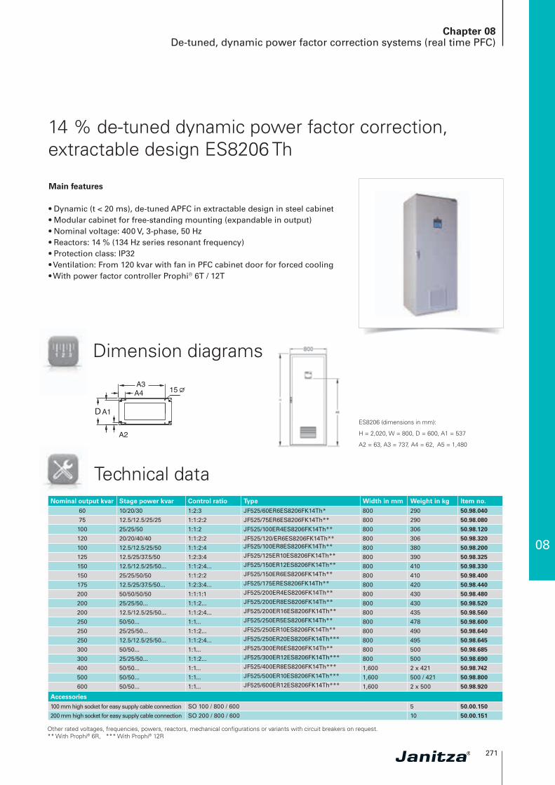
14 % de-tuned dynamic power factor correction, extractable design ES8206 Th
Main features
• Dynamic (t < 20 ms), de-tuned APFC in extractable design in steel cabinet• Modular cabinet for free-standing mounting (expandable in output)• Nominal voltage: 400 V, 3-phase, 50 Hz• Reactors: 14 % (134 Hz series resonant frequency)• Protection class: IP32• Ventilation: From 120 kvar with fan in PFC cabinet door for forced cooling• With power factor controller Prophi® 6T / 12T
Technical dataNominal output kvar Stage power kvar Control ratio Type Width in mm Weight in kg Item no.
60 10/20/30 1:2:3 JF525/60ER6ES8206FK14Th* 800 290 50.98.040
75 12.5/12.5/25/25 1:1:2:2 JF525/75ER6ES8206FK14Th** 800 290 50.98.080
100 25/25/50 1:1:2 JF525/100ER4ES8206FK14Th** 800 306 50.98.120
120 20/20/40/40 1:1:2:2 JF525/120/ER6ES8206FK14Th** 800 306 50.98.320
100 12.5/12.5/25/50 1:1:2:4 JF525/100ER8ES8206FK14Th** 800 380 50.98.200
125 12.5/25/37.5/50 1:2:3:4 JF525/125ER10ES8206FK14Th** 800 390 50.98.325
150 12.5/12.5/25/50... 1:1:2:4... JF525/150ER12ES8206FK14Th** 800 410 50.98.330
150 25/25/50/50 1:1:2:2 JF525/150ER6ES8206FK14Th** 800 410 50.98.400
175 12.5/25/37.5/50... 1:2:3:4... JF525/175ERES8206FK14Th** 800 420 50.98.440
200 50/50/50/50 1:1:1:1 JF525/200ER4ES8206FK14Th** 800 430 50.98.480
200 25/25/50... 1:1:2... JF525/200ER8ES8206FK14Th** 800 430 50.98.520
200 12.5/12.5/25/50... 1:1:2:4... JF525/200ER16ES8206FK14Th** 800 435 50.98.560
250 50/50... 1:1... JF525/250ER5ES8206FK14Th** 800 478 50.98.600
250 25/25/50... 1:1:2... JF525/250ER10ES8206FK14Th** 800 490 50.98.640
250 12.5/12.5/25/50... 1:1:2:4... JF525/250ER20ES8206FK14Th*** 800 495 50.98.645
300 50/50... 1:1... JF525/300ER6ES8206FK14Th** 800 500 50.98.685
300 25/25/50... 1:1:2... JF525/300ER12ES8206FK14Th*** 800 500 50.98.690
400 50/50... 1:1... JF525/400ER8ES8206FK14Th*** 1,600 2 x 421 50.98.742
500 50/50... 1:1... JF525/500ER10ES8206FK14Th*** 1,600 500 / 421 50.98.800
600 50/50... 1:1... JF525/600ER12ES8206FK14Th*** 1,600 2 x 500 50.98.920
Accessories100 mm high socket for easy supply cable connection SO 100 / 800 / 600 5 50.00.150
200 mm high socket for easy supply cable connection SO 200 / 800 / 600 10 50.00.151
Other rated voltages, frequencies, powers, reactors, mechanical configurations or variants with circuit breakers on request. ** With Prophi® 6R, *** With Prophi® 12R
D
W
D
W
ES8206 (dimensions in mm):
H = 2,020, W = 800, D = 600, A1 = 537
A2 = 63, A3 = 737, A4 = 62, A5 = 1,480
Dimension diagrams
272
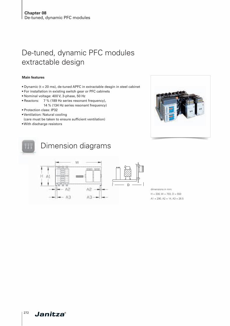
Chapter 08De-tuned, dynamic PFC modules
De-tuned, dynamic PFC modules extractable design
Main features
• Dynamic (t < 20 ms), de-tuned APFC in extractable desgin in steel cabinet• For installation in existing switch gear or PFC cabinets• Nominal voltage: 400 V, 3-phase, 50 Hz• Reactors: 7 % (189 Hz series resonant frequency), 14 % (134 Hz series resonant frequency)• Protection class: IP32• Ventilation: Natural cooling (care must be taken to ensure sufficient ventilation)
• With discharge resistors
Dimension diagrams
dimensions in mm:
H = 330, W = 703, D = 550
A1 = 290, A2 = 14, A3 = 26.5
W
D
W
08
273
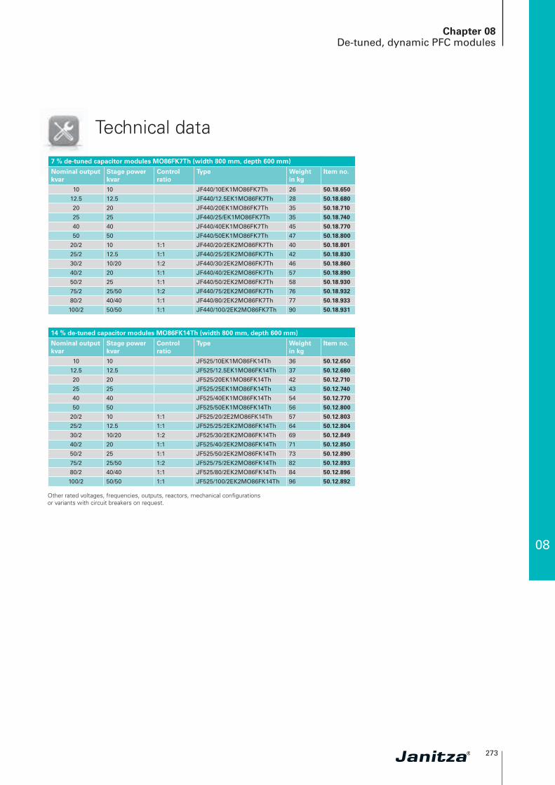
Technical data
7 % de-tuned capacitor modules MO86FK7Th (width 800 mm, depth 600 mm)
Nominal outputkvar
Stage power kvar
Controlratio
Type Weight in kg
Item no.
10 10 JF440/10EK1MO86FK7Th 26 50.18.650
12.5 12.5 JF440/12.5EK1MO86FK7Th 28 50.18.680
20 20 JF440/20EK1MO86FK7Th 35 50.18.710
25 25 JF440/25/EK1MO86FK7Th 35 50.18.740
40 40 JF440/40EK1MO86FK7Th 45 50.18.770
50 50 JF440/50EK1MO86FK7Th 47 50.18.800
20/2 10 1:1 JF440/20/2EK2MO86FK7Th 40 50.18.801
25/2 12.5 1:1 JF440/25/2EK2MO86FK7Th 42 50.18.830
30/2 10/20 1:2 JF440/30/2EK2MO86FK7Th 46 50.18.860
40/2 20 1:1 JF440/40/2EK2MO86FK7Th 57 50.18.890
50/2 25 1:1 JF440/50/2EK2MO86FK7Th 58 50.18.930
75/2 25/50 1:2 JF440/75/2EK2MO86FK7Th 76 50.18.932
80/2 40/40 1:1 JF440/80/2EK2MO86FK7Th 77 50.18.933
100/2 50/50 1:1 JF440/100/2EK2MO86FK7Th 90 50.18.931
Chapter 08De-tuned, dynamic PFC modules
14 % de-tuned capacitor modules MO86FK14Th (width 800 mm, depth 600 mm)
Nominal outputkvar
Stage power kvar
Controlratio
Type Weight in kg
Item no.
10 10 JF525/10EK1MO86FK14Th 36 50.12.650
12.5 12.5 JF525/12.5EK1MO86FK14Th 37 50.12.680
20 20 JF525/20EK1MO86FK14Th 42 50.12.710
25 25 JF525/25EK1MO86FK14Th 43 50.12.740
40 40 JF525/40EK1MO86FK14Th 54 50.12.770
50 50 JF525/50EK1MO86FK14Th 56 50.12.800
20/2 10 1:1 JF525/20/2E2MO86FK14Th 57 50.12.803
25/2 12.5 1:1 JF525/25/2EK2MO86FK14Th 64 50.12.804
30/2 10/20 1:2 JF525/30/2EK2MO86FK14Th 69 50.12.849
40/2 20 1:1 JF525/40/2EK2MO86FK14Th 71 50.12.850
50/2 25 1:1 JF525/50/2EK2MO86FK14Th 73 50.12.890
75/2 25/50 1:2 JF525/75/2EK2MO86FK14Th 82 50.12.893
80/2 40/40 1:1 JF525/80/2EK2MO86FK14Th 84 50.12.896
100/2 50/50 1:1 JF525/100/2EK2MO86FK14Th 96 50.12.892
Other rated voltages, frequencies, outputs, reactors, mechanical configurations or variants with circuit breakers on request.
274
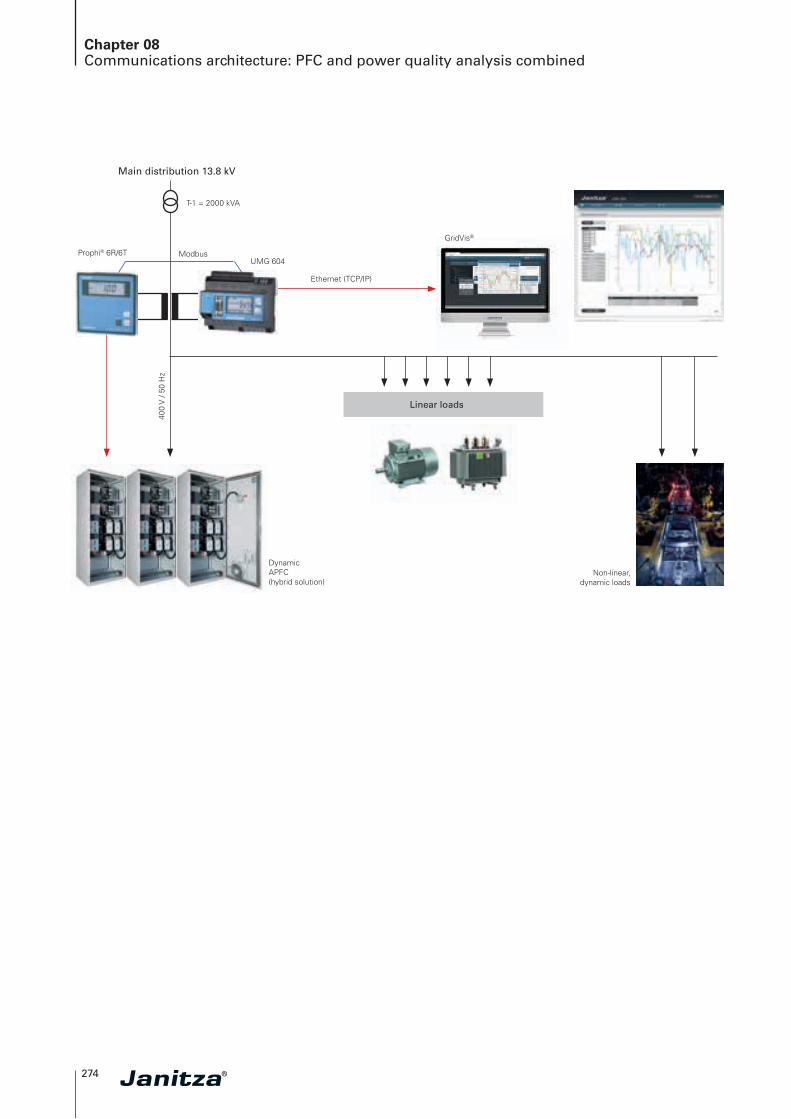
Chapter 08Communications architecture: PFC and power quality analysis combined
Prophi® 6R/6TUMG 604
400
V /
50 H
z
Linear loads
Main distribution 13.8 kV
T-1 = 2000 kVA
Ethernet (TCP/IP)
Modbus
Dynamic APFC (hybrid solution)
Non-linear, dynamic loads
GridVis®

08
275
Chapter 08PFC-Accessories
Power factor correction spare parts and accessories
Capacitor contactors
HRC fuses
Reactors
Capacitors
✔
276
Chapter 08Spare parts list
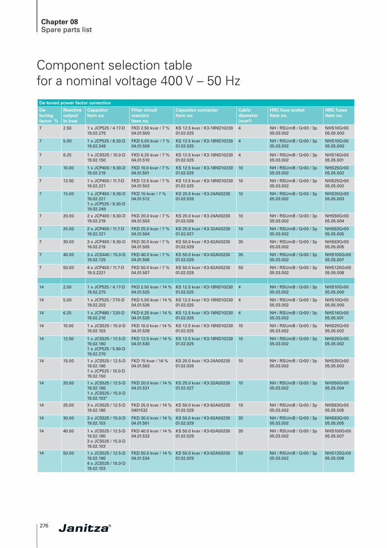
Component selection table for a nominal voltage 400 V – 50 Hz
De-tuned power factor correction
De-tuningfactor %
Reactiveoutput in kvar
CapacitorItem no.
Filter circuit reactors Item no.
Capacitor contactorItem no.
Cable diameter(mm²)
HRC fuse socket Item no.
HRC fuses Item no.
7 2.50 1 x JCP525 / 4.17-D19.02.275
FKD 2.50 kvar / 7 %04.01.500
KS 12.5 kvar / K3-18ND1023001.02.025
4 NH / RSUmB / Gr00 / 3p05.03.002
NHS10Gr0005.05.000
7 5.00 1 x JCP525 / 8.33-D19.02.249
FKD 5.00 kvar / 7 %04.01.509
KS 12.5 kvar / K3-18ND1023001.02.025
4 NH / RSUmB / Gr00 / 3p05.03.002
NHS10Gr0005.05.000
7 6.25 1 x JCS525 / 10.0-D19.02.150
FKD 6.25 kvar / 7 %04.01.510
KS 12.5 kvar / K3-18ND1023001.02.025
4 NH / RSUmB / Gr00 / 3p05.03.002
NHS16Gr0005.05.001
7 10.00 1 x JCP400 / 9.30-D19.02.219
FKD 10.0 kvar / 7 %04.01.501
KS 12.5 kvar / K3-18ND1023001.02.025
10 NH / RSUmB / Gr00 / 3p05.03.002
NHS25Gr0005.05.002
7 12.50 1 x JCP400 / 11.7-D19.02.221
FKD 12.5 kvar / 7 %04.01.502
KS 12.5 kvar / K3-18ND1023001.02.025
10 NH / RSUmB / Gr00 / 3p05.03.002
NHS25Gr0005.05.002
7 15.00 1 x JCP400 / 9.30-D 19.02.221 1 x JCP525 / 8.30-D19.02.249
FKD 15 kvar / 7 %04.01.512
KS 20.0 kvar / K3-24A0023001.02.026
10 NH / RSUmB / Gr00 / 3p05.03.002
NHS35Gr0005.05.003
7 20.00 2 x JCP400 / 9.30-D19.02.219
FKD 20.0 kvar / 7 %04.01.503
KS 20.0 kvar / K3-24A0023001.02.026
10 NH / RSUmB / Gr00 / 3p05.03.002
NHS50Gr0005.05.004
7 25.00 2 x JCP400 / 11.7-D19.02.221
FKD 25.0 kvar / 7 %04.01.504
KS 25.0 kvar / K3-32A0023001.02.027
16 NH / RSUmB / Gr00 / 3p05.03.002
NHS63Gr0005.05.005
7 30.00 3 x JCP400 / 9.30-D19.02.219
FKD 30.0 kvar / 7 %04.01.505
KS 50.0 kvar / K3-62A0023001.02.029
35 NH / RSUmB / Gr00 / 3p05.03.002
NHS63Gr0005.05.005
7 40.00 3 x JCS440 / 15.0-D19.02.125
FKD 40.0 kvar / 7 %04.01.506
KS 50.0 kvar / K3-62A0023001.02.029
35 NH / RSUmB / Gr00 / 3p05.03.002
NHS100Gr0005.05.007
7 50.00 4 x JCP400 / 11.7-D19.0.2221
FKD 50.0 kvar / 7 %04.01.507
KS 50.0 kvar / K3-62A0023001.02.029
50 NH / RSUmB / Gr00 / 3p05.03.002
NHS125Gr0005.05.008
14 2.50 1 x JCP525 / 4.17-D19.02.275
FKD 2.50 kvar / 14 %04.01.525
KS 12.5 kvar / K3-18ND1023001.02.025
4 NH / RSUmB / Gr00 / 3p05.03.002
NHS10Gr0005.05.000
14 5.00 1 x JCP525 / 7.70-D19.02.202
FKD 5.00 kvar / 14 %04.01.526
KS 12.5 kvar / K3-18ND1023001.02.025
4 NH / RSUmB / Gr00 / 3p05.03.002
NHS10Gr0005.05.000
14 6.25 1 x JCP480 / 7.20-D19.02.210
FKD 6.25 kvar / 14 %04.01.529
KS 12.5 kvar / K3-18ND1023001.02.025
4 NH / RSUmB / Gr00 / 3p05.03.002
NHS16Gr0005.05.001
14 10.00 1 x JCS525 / 15.0-D19.02.103
FKD 10.0 kvar / 14 %04.01.528
KS 12.5 kvar / K3-18ND1023001.02.025
10 NH / RSUmB / Gr00 / 3p05.03.002
NHS25Gr0005.05.002
14 12.50 1 x JCS525 / 12.5-D 19.02.1801 x JCP525 / 5.90-D19.02.270
FKD 12.5 kvar / 14 %04.01.530
KS 12.5 kvar / K3-18ND1023001.02.025
10 NH / RSUmB / Gr00 / 3p05.03.002
NHS25Gr0005.05.002
14 15.00 1 x JCS525 / 12.5-D 19.02.1801 x JCP525 / 10.0-D19.02.150
FKD 15 kvar / 14 %04.01.563
KS 20.0 kvar / K3-24A0023001.02.026
10 NH / RSUmB / Gr00 / 3p05.03.002
NHS35Gr0005.05.003
14 20.00 1 x JCS525 / 12.5-D 19.02.1801 x JCS525 / 15.0-D19.02.103“
FKD 20.0 kvar / 14 %04.01.531
KS 25.0 kvar / K3-32A0023001.02.027
10 NH / RSUmB / Gr00 / 3p05.03.002
NHS50Gr0005.05.004
14 25.00 3 x JCS525 / 12.5-D19.02.180
FKD 25.0 kvar / 14 %0401532
KS 50.0 kvar / K3-62A0023001.02.029
16 NH / RSUmB / Gr00 / 3p05.03.002
NHS63Gr0005.05.005
14 30.00 3 x JCS525 / 15.0-D19.02.103
FKD 30.0 kvar / 14 %04.01.561
KS 50.0 kvar / K3-62A0023001.02.029
35 NH / RSUmB / Gr00 / 3p05.03.002
NHS63Gr0005.05.005
14 40.00 1 x JCS525 / 12.5-D 19.02.1803 x JCS525 / 15.0-D19.02.103
FKD 40.0 kvar / 14 %04.01.533
KS 50.0 kvar / K3-62A0023001.02.029
35 NH / RSUmB / Gr00 / 3p05.03.002
NHS100Gr0005.05.007
14 50.00 1 x JCS525 / 12.5-D 19.02.1804 x JCS525 / 15.0-D19.02.103
FKD 50.0 kvar / 14 %04.01.534
KS 50.0 kvar / K3-62A0023001.02.029
50 NH / RSUmB / Gr00 / 3p05.03.002
NHS125Gr0005.05.008
08
277
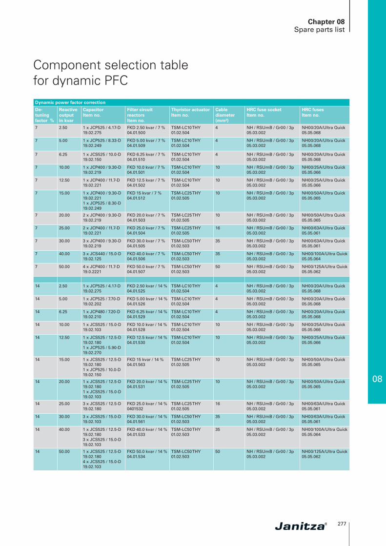
Component selection table for dynamic PFCDynamic power factor correction
De-tuningfactor %
Reactiveoutput in kvar
CapacitorItem no.
Filter circuit reactorsItem no.
Thyristor actuatorItem no.
Cable diameter(mm²)
HRC fuse socket Item no.
HRC fuses Item no.
7 2.50 1 x JCP525 / 4.17-D19.02.275
FKD 2.50 kvar / 7 %04.01.500
TSM-LC10 THY01.02.504
4 NH / RSUmB / Gr00 / 3p05.03.002
NH00/20A/Ultra Quick05.05.068
7 5.00 1 x JCP525 / 8.33-D19.02.249
FKD 5.00 kvar / 7 %04.01.509
TSM-LC10 THY01.02.504
4 NH / RSUmB / Gr00 / 3p05.03.002
NH00/20A/Ultra Quick05.05.068
7 6.25 1 x JCS525 / 10.0-D19.02.150
FKD 6.25 kvar / 7 %04.01.510
TSM-LC10 THY01.02.504
4 NH / RSUmB / Gr00 / 3p05.03.002
NH00/20A/Ultra Quick05.05.068
7 10.00 1 x JCP400 / 9.30-D19.02.219
FKD 10.0 kvar / 7 %04.01.501
TSM-LC10 THY01.02.504
10 NH / RSUmB / Gr00 / 3p05.03.002
NH00/25A/Ultra Quick05.05.066
7 12.50 1 x JCP400 / 11.7-D19.02.221
FKD 12.5 kvar / 7 %04.01.502
TSM-LC10 THY01.02.504
10 NH / RSUmB / Gr00 / 3p05.03.002
NH00/25A/Ultra Quick05.05.066
7 15.00 1 x JCP400 / 9.30-D 19.02.221 1 x JCP525 / 8.30-D19.02.249
FKD 15 kvar / 7 %04.01.512
TSM-LC25 THY01.02.505
10 NH / RSUmB / Gr00 / 3p05.03.002
NH00/50A/Ultra Quick05.05.065
7 20.00 2 x JCP400 / 9.30-D19.02.219
FKD 20.0 kvar / 7 %04.01.503
TSM-LC25 THY01.02.505
10 NH / RSUmB / Gr00 / 3p05.03.002
NH00/50A/Ultra Quick05.05.065
7 25.00 2 x JCP400 / 11.7-D19.02.221
FKD 25.0 kvar / 7 %04.01.504
TSM-LC25 THY01.02.505
16 NH / RSUmB / Gr00 / 3p05.03.002
NH00/63A/Ultra Quick05.05.061
7 30.00 3 x JCP400 / 9.30-D19.02.219
FKD 30.0 kvar / 7 %04.01.505
TSM-LC50 THY01.02.503
35 NH / RSUmB / Gr00 / 3p05.03.002
NH00/63A/Ultra Quick05.05.061
7 40.00 3 x JCS440 / 15.0-D19.02.125
FKD 40.0 kvar / 7 %04.01.506
TSM-LC50 THY01.02.503
35 NH / RSUmB / Gr00 / 3p05.03.002
NH00/100A/Ultra Quick05.05.064
7 50.00 4 x JCP400 / 11.7-D19.0.2221
FKD 50.0 kvar / 7 %04.01.507
TSM-LC50 THY01.02.503
50 NH / RSUmB / Gr00 / 3p05.03.002
NH00/125A/Ultra Quick05.05.062
14 2.50 1 x JCP525 / 4.17-D19.02.275
FKD 2.50 kvar / 14 %04.01.525
TSM-LC10 THY01.02.504
4 NH / RSUmB / Gr00 / 3p05.03.002
NH00/20A/Ultra Quick05.05.068
14 5.00 1 x JCP525 / 7.70-D19.02.202
FKD 5.00 kvar / 14 %04.01.526
TSM-LC10 THY01.02.504
4 NH / RSUmB / Gr00 / 3p05.03.002
NH00/20A/Ultra Quick05.05.068
14 6.25 1 x JCP480 / 7.20-D19.02.210
FKD 6.25 kvar / 14 %04.01.529
TSM-LC10 THY01.02.504
4 NH / RSUmB / Gr00 / 3p05.03.002
NH00/20A/Ultra Quick05.05.068
14 10.00 1 x JCS525 / 15.0-D19.02.103
FKD 10.0 kvar / 14 %04.01.528
TSM-LC10 THY01.02.504
10 NH / RSUmB / Gr00 / 3p05.03.002
NH00/25A/Ultra Quick05.05.066
14 12.50 1 x JCS525 / 12.5-D 19.02.1801 x JCP525 / 5.90-D19.02.270
FKD 12.5 kvar / 14 %04.01.530
TSM-LC10 THY01.02.504
10 NH / RSUmB / Gr00 / 3p05.03.002
NH00/25A/Ultra Quick05.05.066
14 15.00 1 x JCS525 / 12.5-D 19.02.1801 x JCP525 / 10.0-D19.02.150
FKD 15 kvar / 14 %04.01.563
TSM-LC25 THY01.02.505
10 NH / RSUmB / Gr00 / 3p05.03.002
NH00/50A/Ultra Quick05.05.065
14 20.00 1 x JCS525 / 12.5-D 19.02.1801 x JCS525 / 15.0-D19.02.103
FKD 20.0 kvar / 14 %04.01.531
TSM-LC25 THY01.02.505
10 NH / RSUmB / Gr00 / 3p05.03.002
NH00/50A/Ultra Quick05.05.065
14 25.00 3 x JCS525 / 12.5-D19.02.180
FKD 25.0 kvar / 14 %0401532
TSM-LC25 THY01.02.505
16 NH / RSUmB / Gr00 / 3p05.03.002
NH00/63A/Ultra Quick05.05.061
14 30.00 3 x JCS525 / 15.0-D19.02.103
FKD 30.0 kvar / 14 %04.01.561
TSM-LC50 THY01.02.503
35 NH / RSUmB / Gr00 / 3p05.03.002
NH00/63A/Ultra Quick05.05.061
14 40.00 1 x JCS525 / 12.5-D 19.02.1803 x JCS525 / 15.0-D19.02.103
FKD 40.0 kvar / 14 %04.01.533
TSM-LC50 THY01.02.503
35 NH / RSUmB / Gr00 / 3p05.03.002
NH00/100A/Ultra Quick05.05.064
14 50.00 1 x JCS525 / 12.5-D 19.02.1804 x JCS525 / 15.0-D19.02.103
FKD 50.0 kvar / 14 %04.01.534
TSM-LC50 THY01.02.503
50 NH / RSUmB / Gr00 / 3p05.03.002
NH00/125A/Ultra Quick05.05.062
Chapter 08Spare parts list
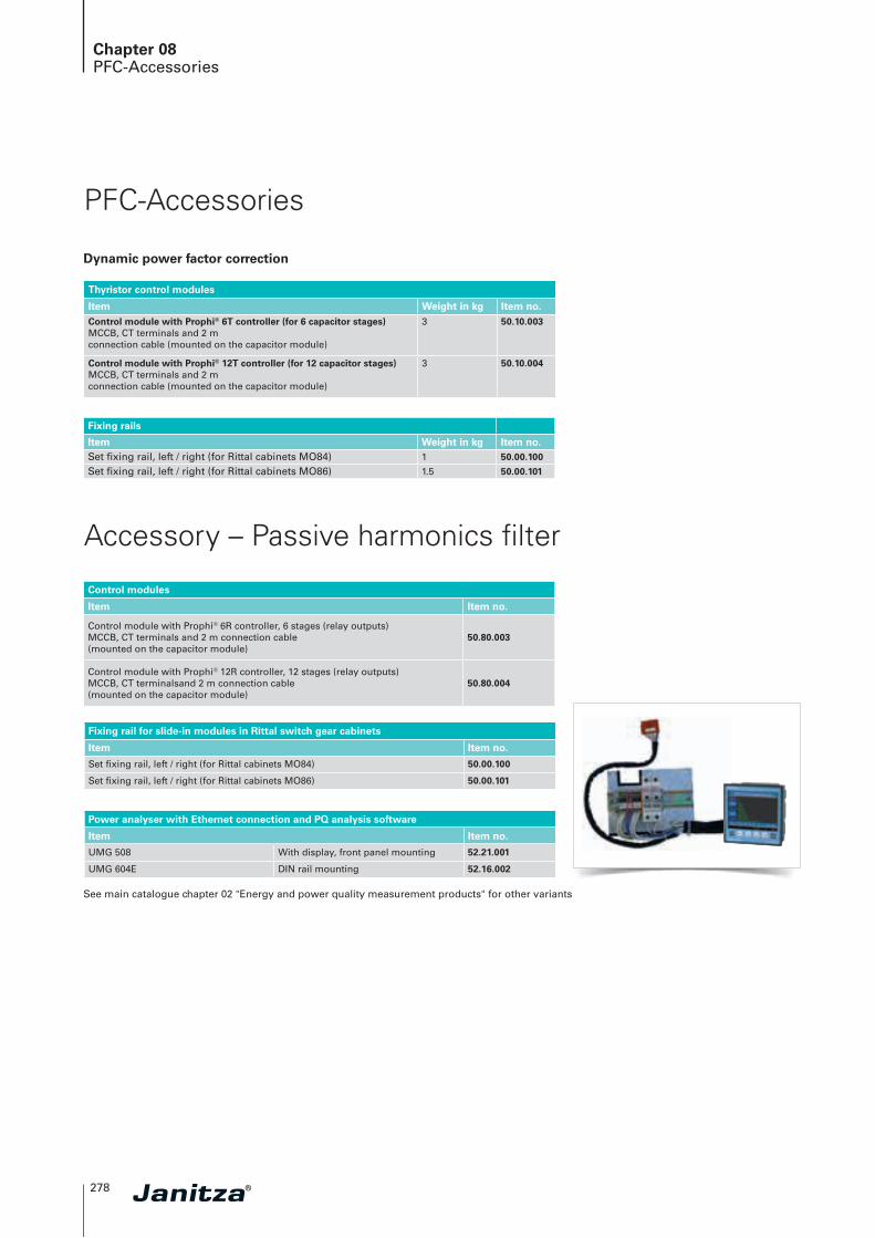
278
Chapter 08PFC-Accessories
Accessory – Passive harmonics filter
Control modules
Item Item no.
Control module with Prophi® 6R controller, 6 stages (relay outputs)MCCB, CT terminals and 2 m connection cable (mounted on the capacitor module)
50.80.003
Control module with Prophi® 12R controller, 12 stages (relay outputs)MCCB, CT terminalsand 2 m connection cable (mounted on the capacitor module)
50.80.004
Fixing rail for slide-in modules in Rittal switch gear cabinets
Item Item no.
Set fixing rail, left / right (for Rittal cabinets MO84) 50.00.100
Set fixing rail, left / right (for Rittal cabinets MO86) 50.00.101
Power analyser with Ethernet connection and PQ analysis software
Item Item no.
UMG 508 With display, front panel mounting 52.21.001
UMG 604E DIN rail mounting 52.16.002
See main catalogue chapter 02 "Energy and power quality measurement products" for other variants
Dynamic power factor correction
PFC-Accessories
Thyristor control modules
Item Weight in kg Item no.Control module with Prophi® 6T controller (for 6 capacitor stages)MCCB, CT terminals and 2 m connection cable (mounted on the capacitor module)
3 50.10.003
Control module with Prophi® 12T controller (for 12 capacitor stages)MCCB, CT terminals and 2 m connection cable (mounted on the capacitor module)
3 50.10.004
Fixing rails
Item Weight in kg Item no.Set fixing rail, left / right (for Rittal cabinets MO84) 1 50.00.100
Set fixing rail, left / right (for Rittal cabinets MO86) 1.5 50.00.101

08
Chapter 08PQS – Power Quality Solutions
279