powerbox industrial line dc/dc converter manual … · 6.7 test set-up p12 6.8 output voltage...
TRANSCRIPT
1www.prbx.com
Table of Contents1. Introduction P12. Electrical converter features P13. Electrical block diagram P24. Technical specification P35. Main features and functions P65.1 Operating temperature range P65.2 Output voltage adjustment P65.3 Over current protection P65.4 Output over voltage protection P65.5 Remote On/Off P65.6 UVLO & OVLO (under/over voltage lock out) P65.7 Over temperature range P66. Applications P66.1 Recommended layout, PCB footprint and soldering information P66.2 Convection requirements for cooling P76.3 Thermal considerations P76.4 Power de-rating P86.5 Full brick heat sinks P96.6 Efficiency VS load P106.7 Test set-up P126.8 Output voltage adjustment P126.9 Output remote sensing P136.10 Output ripple and noise P136.11 Output capacitance P136.12 Paralel operation P136.13 IOC signal P146.14 Auxiliary power for output signal P146.15 On/Off control P147. Safety & EMC P157.1 Input fusing and safety considerations P157.2 EMC considerations P158. Part number P179. Mechanical specifications P179.1 Mechanical outline diagrams P17
POWERBOX Industrial LinePFB600 Series600-700W 2:1 Single OutputDC/DC ConverterManual V17
www.prbx.com
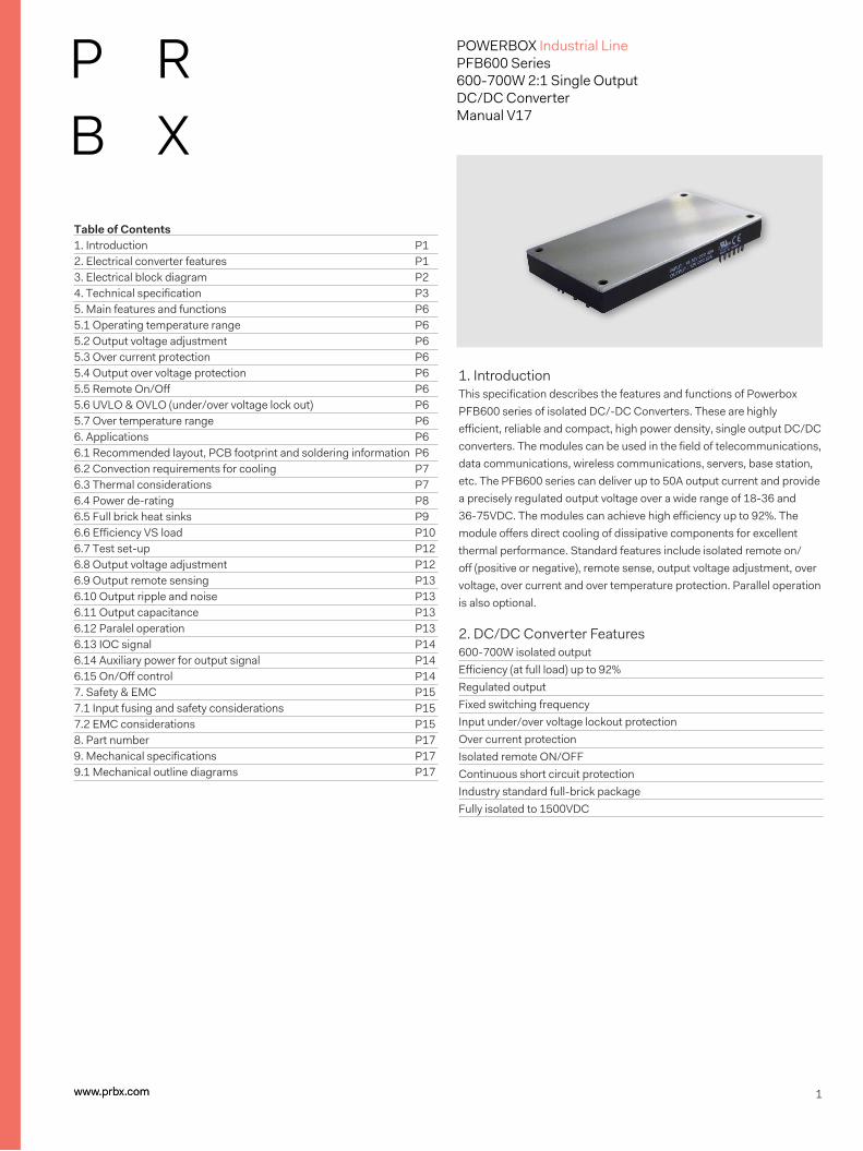
1. IntroductionThis specification describes the features and functions of Powerbox PFB600 series of isolated DC/-DC Converters. These are highly efficient, reliable and compact, high power density, single output DC/DC converters. The modules can be used in the field of telecommunications, data communications, wireless communications, servers, base station, etc. The PFB600 series can deliver up to 50A output current and provide a precisely regulated output voltage over a wide range of 18-36 and 36-75VDC. The modules can achieve high efficiency up to 92%. The module offers direct cooling of dissipative components for excellent thermal performance. Standard features include isolated remote on/off (positive or negative), remote sense, output voltage adjustment, over voltage, over current and over temperature protection. Parallel operation is also optional. 2. DC/DC Converter Features600-700W isolated outputEfficiency (at full load) up to 92%Regulated outputFixed switching frequencyInput under/over voltage lockout protectionOver current protectionIsolated remote ON/OFFContinuous short circuit protectionIndustry standard full-brick packageFully isolated to 1500VDC
2www.prbx.com
POWERBOX Industrial LinePFB600 Series600-700W 2:1 Single OutputDC/DC ConverterManual V17
+VIN
-VIN
+ON/OFF
-ON/OFF
+VOUT
-VOUT
+SENSE
-SENSE
TRIM
AUX
IOC
PC/NC
(2)
(1)
(3)
(4)
(5, 6, 7)
(8, 9, 10)
(11)
(12)
(13)
(14)
(15)
(16)
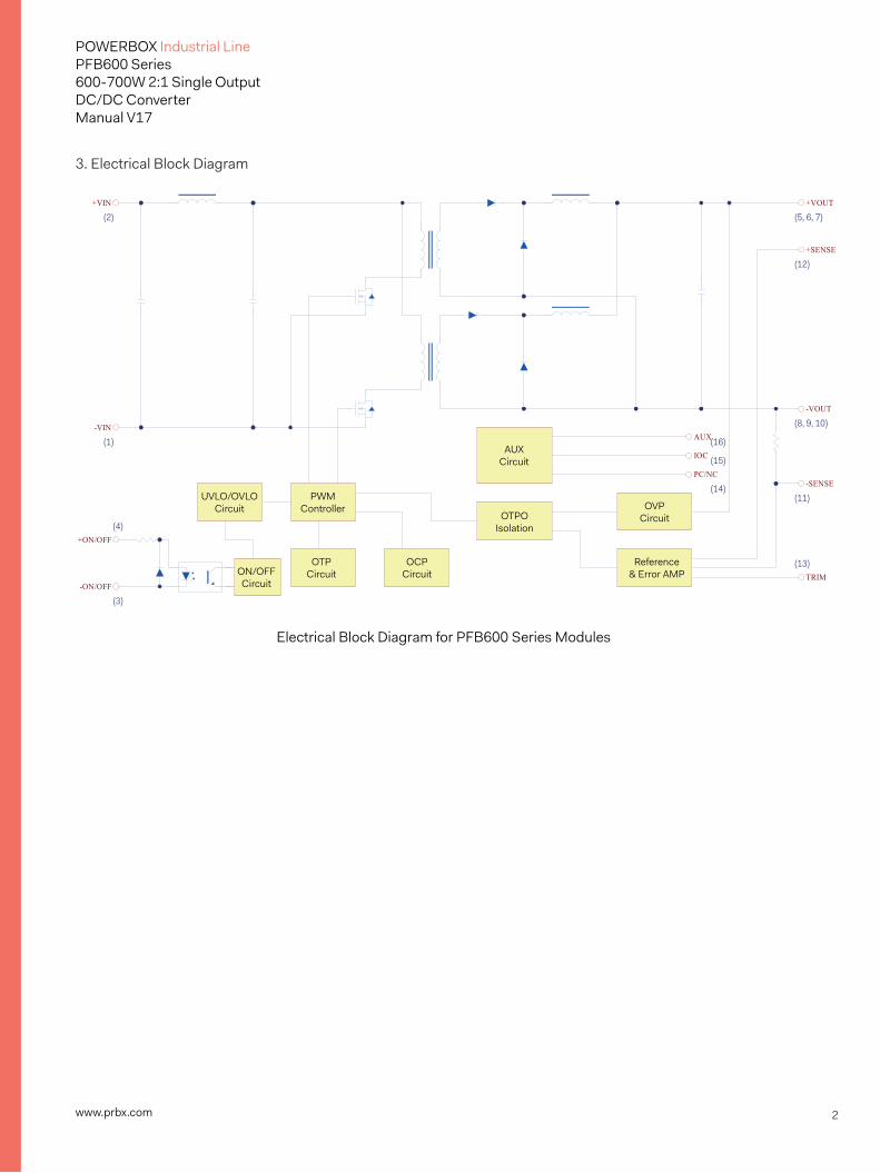
Electrical Block Diagram for PFB600 Series Modules
UVLO/OVLOCircuit
PWMController
AUXCircuit
OTPOIsolation
ON/OFFCircuit
OTPCircuit
OCPCircuit
OVPCircuit
Reference& Error AMP
3. Electrical Block Diagram
3www.prbx.com
POWERBOX Industrial LinePFB600 Series600-700W 2:1 Single OutputDC/DC ConverterManual V17
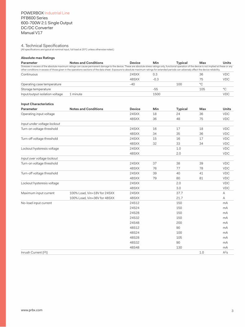
4. Technical Specifications(All specifications are typical at nominal input, full load at 25°C unless otherwise noted.)
Absolute max Ratings Parameter Notes and Conditions Device Min Typical Max UnitsStresses in excess of the absolute maximum ratings can cause permanent damage to the device. These are absolute stress ratings only, functional operation of the device is not implied at these or any other conditions in excess of those given in the operations sections of the data sheet. Exposure to absolute maximum ratings for extended periods can adversely affect the device reliability.
Continuous 24SXX 0.3 36 VDC 48SXX -0.3 75 VDCOperating case temperature -40 100 °CStorage temperature -55 105 °CInput/output isolation voltage 1 minute 1500 VDC Input Characteristics Parameter Notes and Conditions Device Min Typical Max UnitsOperating input voltage 24SXX 18 24 36 VDC 48SXX 36 48 75 VDCInput under voltage lockoutTurn-on voltage threshold 24SXX 16 17 18 VDC 48SXX 34 35 36 VDCTurn-off voltage threshold 24SXX 15 16 17 VDC 48SXX 32 33 34 VDCLockout hysteresis voltage 24SXX 1.0 VDC 48SXX 2.0 VDCInput over voltage lockoutTurn-on voltage threshold 24SXX 37 38 39 VDC 48SXX 76 77 78 VDCTurn-off voltage threshold 24SXX 39 40 41 VDC 48SXX 79 80 81 VDCLockout hysteresis voltage 24SXX 2.0 VDC 48SXX 3.0 VDCMaximum input current 100% Load, Vin=18V for 24SXX 24SXX 37.7 A 100% Load, Vin=36V for 48SXX 48SXX 21.7 A No-load input current 24S12 150 mA 24S24 150 mA 24S28 150 mA 24S32 150 mA 24S48 200 mA 48S12 90 mA 48S24 100 mA 48S28 105 mA 48S32 90 mA 48S48 130 mAInrush Current (I2t) 1.0 A2s
4www.prbx.com
POWERBOX Industrial LinePFB600 Series600-700W 2:1 Single OutputDC/DC ConverterManual V17
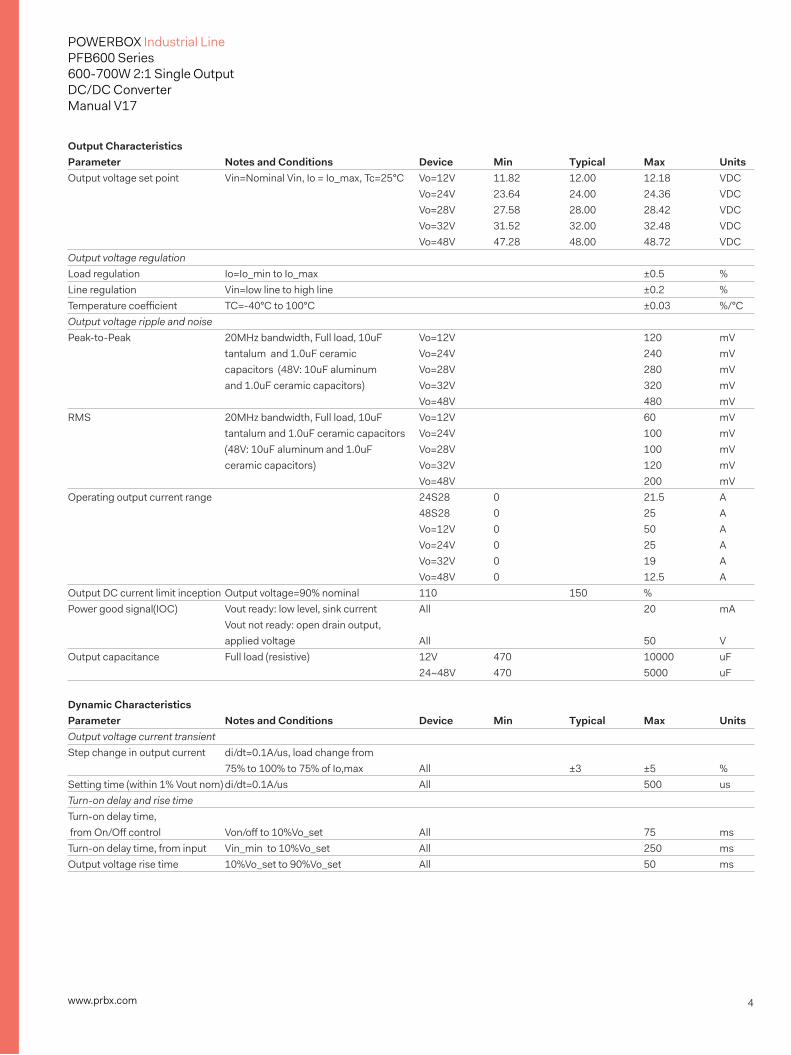
Output Characteristics Parameter Notes and Conditions Device Min Typical Max UnitsOutput voltage set point Vin=Nominal Vin, Io = Io_max, Tc=25°C Vo=12V 11.82 12.00 12.18 VDC Vo=24V 23.64 24.00 24.36 VDC Vo=28V 27.58 28.00 28.42 VDC Vo=32V 31.52 32.00 32.48 VDC Vo=48V 47.28 48.00 48.72 VDCOutput voltage regulationLoad regulation Io=Io_min to Io_max ±0.5 %Line regulation Vin=low line to high line ±0.2 %Temperature coefficient TC=-40°C to 100°C ±0.03 %/°COutput voltage ripple and noisePeak-to-Peak 20MHz bandwidth, Full load, 10uF Vo=12V 120 mV tantalum and 1.0uF ceramic Vo=24V 240 mV capacitors (48V: 10uF aluminum Vo=28V 280 mV and 1.0uF ceramic capacitors) Vo=32V 320 mV Vo=48V 480 mVRMS 20MHz bandwidth, Full load, 10uF Vo=12V 60 mV tantalum and 1.0uF ceramic capacitors Vo=24V 100 mV (48V: 10uF aluminum and 1.0uF Vo=28V 100 mV ceramic capacitors) Vo=32V 120 mV Vo=48V 200 mVOperating output current range 24S28 0 21.5 A 48S28 0 25 A Vo=12V 0 50 A Vo=24V 0 25 A Vo=32V 0 19 A Vo=48V 0 12.5 AOutput DC current limit inception Output voltage=90% nominal 110 150 %Power good signal(IOC) Vout ready: low level, sink current All 20 mA Vout not ready: open drain output, applied voltage All 50 VOutput capacitance Full load (resistive) 12V 470 10000 uF 24~48V 470 5000 uF Dynamic Characteristics Parameter Notes and Conditions Device Min Typical Max UnitsOutput voltage current transientStep change in output current di/dt=0.1A/us, load change from 75% to 100% to 75% of Io,max All ±3 ±5 %Setting time (within 1% Vout nom) di/dt=0.1A/us All 500 usTurn-on delay and rise timeTurn-on delay time, from On/Off control Von/off to 10%Vo_set All 75 msTurn-on delay time, from input Vin_min to 10%Vo_set All 250 msOutput voltage rise time 10%Vo_set to 90%Vo_set All 50 ms
5www.prbx.com
POWERBOX Industrial LinePFB600 Series600-700W 2:1 Single OutputDC/DC ConverterManual V17
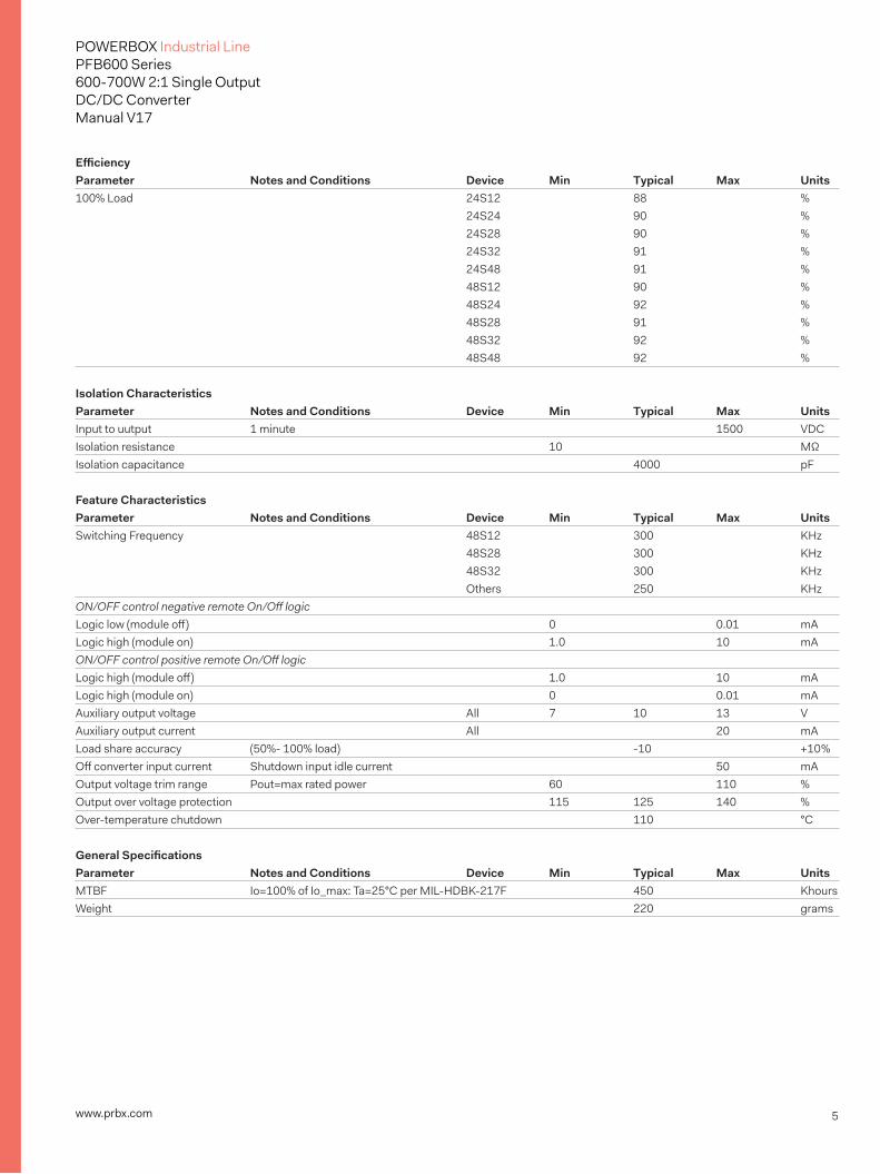
Efficiency Parameter Notes and Conditions Device Min Typical Max Units100% Load 24S12 88 % 24S24 90 % 24S28 90 % 24S32 91 % 24S48 91 % 48S12 90 % 48S24 92 % 48S28 91 % 48S32 92 % 48S48 92 % Isolation Characteristics Parameter Notes and Conditions Device Min Typical Max UnitsInput to uutput 1 minute 1500 VDCIsolation resistance 10 MΩIsolation capacitance 4000 pF Feature Characteristics Parameter Notes and Conditions Device Min Typical Max UnitsSwitching Frequency 48S12 300 KHz 48S28 300 KHz 48S32 300 KHz Others 250 KHzON/OFF control negative remote On/Off logicLogic low (module off) 0 0.01 mALogic high (module on) 1.0 10 mAON/OFF control positive remote On/Off logicLogic high (module off) 1.0 10 mALogic high (module on) 0 0.01 mAAuxiliary output voltage All 7 10 13 VAuxiliary output current All 20 mALoad share accuracy (50%- 100% load) -10 +10 %Off converter input current Shutdown input idle current 50 mAOutput voltage trim range Pout=max rated power 60 110 %Output over voltage protection 115 125 140 %Over-temperature chutdown 110 °C General Specifications Parameter Notes and Conditions Device Min Typical Max UnitsMTBF Io=100% of Io_max: Ta=25°C per MIL-HDBK-217F 450 KhoursWeight 220 grams
6www.prbx.com
POWERBOX Industrial LinePFB600 Series600-700W 2:1 Single OutputDC/DC ConverterManual V17
5. Main Features and Functions 5.1 Operating Temperature RangeThe PFB600 series converters can be operated within a wide case temperature range of -40°C to 100°C. Consideration must be given to the de-rating curves when ascertaining maximum power that can be drawn from the converter. The maximum power drawn from full brick models is influenced by usual factors, such as:• Input voltage range• Output load current• Forced air or natural convection 5.2 Output Voltage AdjustmentSection 6.8 describes in detail how to trim the output voltage with respect to its set point. The output voltage on all models is adjustable within the range of 60% to 110%.
5.3 Over Current ProtectionThe converter is protected against over current or short circuit conditions. At the instance of current-limit inception, the module enters a constant current mode of operation. While the fault condition exists, the module will remain in this constant current mode, and can remain in this mode until the fault is cleared. The unit operates normally once the output current is reduced back into its specified range.
5.4 Output Over Voltage ProtectionThe converter is protected against output over voltage conditions. When the output voltage is higher than the specified range, the module enters a hiccup mode of operation.
5.5 Remote On/OffThe On/Off input pins permit the user to turn the power module on or off via a system signal from the primary side or the secondary side. Two remote on/off options are available. Negative logic turns the module on as long as a current (1-10mA) is flowing between +on/off and –on/off and inactive when no current is flowing. Positive logic turns the module off as long as a current (1-10mA) is flowing between +on/off and – on/off and active when no current is flowing.
5.6 UVLO&OVLO (Under/Over Voltage Lock Out)Input under/over voltage lockout is standard with this converter. At input voltages below/beyond the input under voltage lockout limit, the module operation is disabled. The converter will recover automatically when the input voltage is back within acceptable limits.
5.7 Over Temperature ProtectionThese modules have an over temperature protection circuit to safeguard against thermal damage. When the case temperature rises above over temperature shutdown threshold, the converter will shut down to protect it f rom overheating. The module will automatically restart after it cools down.
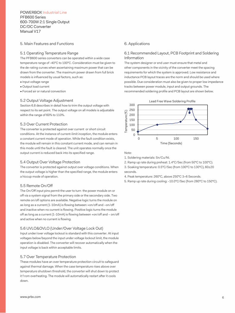
6. Applications 6.1 Recommended Layout, PCB Footprint and Soldering InformationThe system designer or end user must ensure that metal and other components in the vicinity of the converter meet the spacing requirements for which the system is approved. Low resistance and inductance PCB layout traces are the norm and should be used where possible. Due consideration must also be given to proper low impedance tracks between power module, input and output grounds. The recommended soldering profile and PCB layout are shown below.
Note:1. Soldering materials: Sn/Cu/Ni.2. Ramp up rate during preheat: 1.4°C/Sec (from 50°C to 100°C).3. Soaking temperature: 0.5°C/Sec (from 100°C to 130°C), 60±20 seconds.4. Peak temperature: 260°C, above 250°C 3~6 Seconds.5. Ramp up rate during cooling: -10.0°C/Sec (from 260°C to 150°C).
Lead Free Wave Soldering Profile
050
100150200250300
Time (Seconds)
Tem
pera
ture
(°C)
0 5 100 150
7www.prbx.com
POWERBOX Industrial LinePFB600 Series600-700W 2:1 Single OutputDC/DC ConverterManual V17
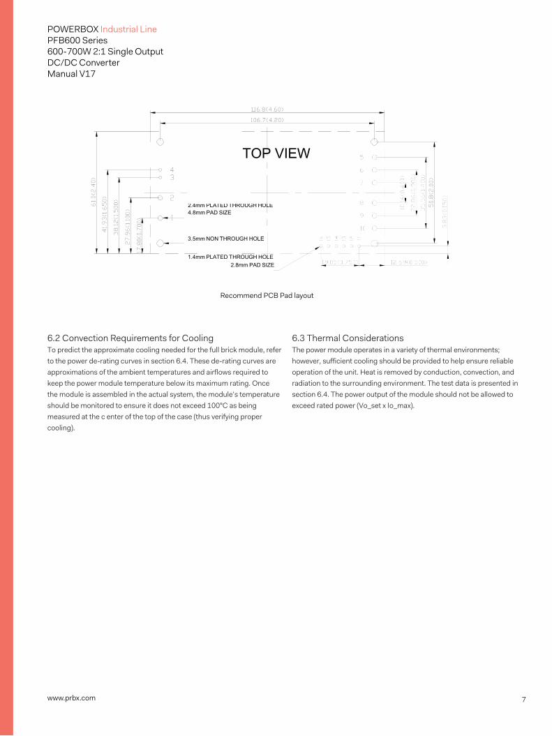
Recommend PCB Pad layout
6.2 Convection Requirements for CoolingTo predict the approximate cooling needed for the full brick module, refer to the power de-rating curves in section 6.4. These de-rating curves are approximations of the ambient temperatures and airflows required to keep the power module temperature below its maximum rating. Once the module is assembled in the actual system, the module’s temperature should be monitored to ensure it does not exceed 100°C as being measured at the c enter of the top of the case (thus verifying proper cooling).
6.3 Thermal ConsiderationsThe power module operates in a variety of thermal environments; however, sufficient cooling should be provided to help ensure reliable operation of the unit. Heat is removed by conduction, convection, and radiation to the surrounding environment. The test data is presented in section 6.4. The power output of the module should not be allowed to exceed rated power (Vo_set x Io_max).
8www.prbx.com
POWERBOX Industrial LinePFB600 Series600-700W 2:1 Single OutputDC/DC ConverterManual V17
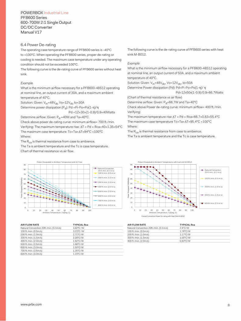
6.4 Power De-ratingThe operating case temperature range of PFB600 series is -40°C to +100°C. When operating the PFB600 series, proper de-rating or cooling is needed. The maximum case temperature under any operating condition should not be exceeded 100°C.The following curve is the de-rating curve of PFB600 series without heat sink.
ExampleWhat is the minimum airflow necessary for a PFB600-48S12 operating at nominal line, an output current of 30A, and a maximum ambient temperature of 40°C.Solution: Given: Vin=48Vdc Vo=12Vdc Io=30A Determine power dissipation (Pd): Pd =Pi-Po=Po(1-h)/h Pd =12×30×(1-0.9)/0.9=40WattsDetermine airflow: Given: Pd =40W and Ta=40°C Check above power de-rating curve: minimum airflow= 700 ft./min.Verifying: The maximum temperature rise: DT = Pd × Rca=40×1.35=54°CThe maximum case temperature: Tc=Ta+DT=94°C <100°CWhere:The Rca is thermal resistance from case to ambience.The Ta is ambient temperature and the Tc is case temperature.Chart of thermal resistance vs air flow.
AIR FLOW RATE TYPICAL RcaNatural Convection 20ft./min. (0.1m/s) 3.82°C /W100 ft./min. (0.5m/s) 3.23°C /W200 ft./min. (1.0m/s) 2.71°C/W300 ft./min. (1.5m/s) 2.28°C/W400 ft./min. (2.0m/s) 1.92°C/W500 ft./min. (2.5m/s) 1.68°C/W600 ft./min. (3.0m/s) 1.50°C/W700 ft./min. (3.5m/s) 1.35°C/W800 ft./min. (4.0m/s) 1.23°C/W
Power Dissipated vs Ambient Temperature and Air Flow
0
10
20
30
40
50
60
70
80
90
0 10 20 30 40 50 60 70 80 90 100Ambient Temperature ,Ta(Deg. C)
Pow
er D
issp
ated
,Pd(
Wat
ts)
Natural Convection 20 ./m in. (0.1 m /s)100 ./m in. (0.5 m /s)
200 ./m in. (1.0 m /s)
300 ./m in. (1.5 m /s)
400 ./m in. (2.0 m /s)
500 ./m in. (2.5 m /s)
600 ./m in. (3.0 m /s)
700 ./m in. (3.5 m /s)
800 ./m in. (4.0 m /s)
AIR FLOW RATE TYPICAL RcaNatural Convection 20ft./min. (0.1m/s) 2.4°C/W100 ft./min. (0.5m/s) 1.76°C/W200 ft./min. (1.0m/s) 1.17°C/W300 ft./min. (1.5m/s) 1.00°C/W400 ft./min. (2.0m/s) 0.83°C/W
Power Diss ipat ed v s Am bie nt Temperatu re with h eat s ink M-B01 2
0
10
20
30
40
50
60
70
80
90
0 1 0 20 30 4 0 50 60 70 80 90 1 00Ambient T em perature ,Ta(Deg. C)
Pow
er D
issp
ated
,Pd(
Wat
ts)
Natu ral C onvectio n 20 ./m in . (0.1 m/s)
10 0 . /min. (0. 5 m /s)
20 0 . /min. (1. 0 m /s)
30 0 . /min. (1. 5 m /s)
40 0 . /min. (2. 0 m /s)
Forced Convection Power De-rating with Heat Sink M-B012
The following curve is the de-rating curve of PFB600 series with heat sink M-B012.
ExampleWhat is the minimum airflow necessary for a PFB600-48S12 operating at nominal line, an output current of 50A, and a maximum ambient temperature of 40°C.Solution: Given: Vin=48Vdc, Vo=12Vdc, Io=50A Determine Power dissipation (Pd): Pd=Pi-Po=Po(1-h)/ h Pd=12x50x(1-0.9)/0.9=66.7Watts (Chart of thermal resistance vs air flow) Determine airflow: Given: Pd=66.7W and Ta=40°C Check above Power de-rating curve: minimum airflow= 400 ft./min.Verifying:The maximum temperature rise DT = Pd × Rca=66.7×0.83=55.4°C The maximum case temperature Tc=Ta+DT=95.4°C <100°CWhere:The Rca is thermal resistance from case to ambience.The Ta is ambient temperature and the Tc is case temperature.
9www.prbx.com
POWERBOX Industrial LinePFB600 Series600-700W 2:1 Single OutputDC/DC ConverterManual V17
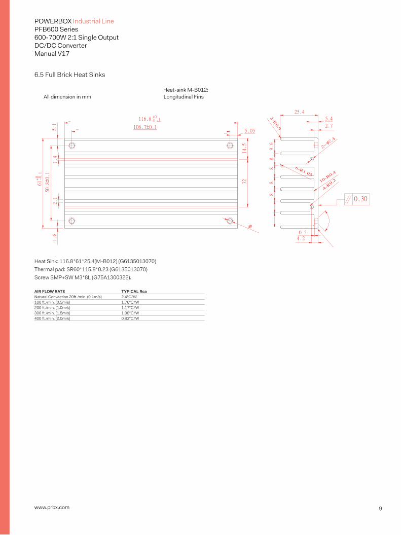
6.5 Full Brick Heat Sinks
Heat Sink: 116.8*61*25.4(M-B012) (G6135013070) Thermal pad: SR60*115.8*0.23 (G6135013070) Screw SMP+SW M3*8L (G75A1300322).
AIR FLOW RATE TYPICAL RcaNatural Convection 20ft./min. (0.1m/s) 2.4°C/W100 ft./min. (0.5m/s) 1.76°C/W200 ft./min. (1.0m/s) 1.17°C/W300 ft./min. (1.5m/s) 1.00°C/W400 ft./min. (2.0m/s) 0.83°C/W
All dimension in mmHeat-sink M-B012:Longitudinal Fins
10www.prbx.com
POWERBOX Industrial LinePFB600 Series600-700W 2:1 Single OutputDC/DC ConverterManual V17
60%
65%
70%
75%
80%
85%
90%
95%
10% 20% 30% 40% 50% 60% 70% 80% 90% 100%Load
Effici
ency
18Vin
24Vin
36Vin
60%
65%
70%
75%
80%
85%
90%
95%
10% 20% 30% 40% 50% 60% 70% 80% 90% 100%Load
Effci
ency
36Vin
48Vin
75Vin
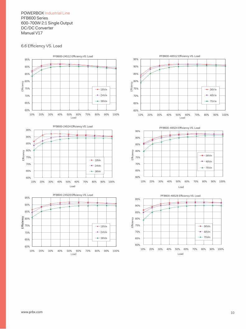
PFB600-24S24 Efficiency VS. Load
60%
65%
70%
75%
80%
85%
90%
95%
10% 20% 30% 40% 50% 60% 70% 80% 90% 100%
Load
Effici
ency
18Vin
24Vin
36Vin
PFB600-48S24 Efficiency VS. Load
60%
65%
70%
75%
80%
85%
90%
95%
10% 20% 30% 40% 50% 60% 70% 80% 90% 100%
Load
Effici
ency
36Vin
48Vin
75Vin
60%
65%
70%
75%
80%
85%
90%
95%
10% 20% 30% 40% 50% 60% 70% 80% 90% 100%Load
Effi
cien
cy
18Vin
24Vin
36Vin
PFB600-48S28 Efficiency VS. Load
60%
65%
70%
75%
80%
85%
90%
95%
10% 20% 30% 40% 50% 60% 70% 80% 90% 100%
Load
Effici
ency
36Vin
48Vin
75Vin
PFB600-24S12 Efficiency VS. Load PFB600-48S12 Efficiency VS. Load
PFB600-24S28 Efficiency VS. Load
6.6 Efficiency VS. Load
11www.prbx.com
POWERBOX Industrial LinePFB600 Series600-700W 2:1 Single OutputDC/DC ConverterManual V17
18Vin
24Vin
36Vin
36Vin
48Vin
75Vin
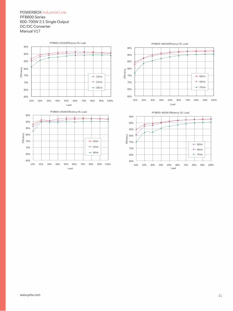
PFB600-24S48 Efficiency VS. Load
60%
65%
70%
75%
80%
85%
90%
95%
10% 20% 30% 40% 50% 60% 70% 80% 90% 100%
Load
Effici
ency
18Vin
24Vin
36Vin
PFB600-48S48 Efficiency VS. Load
60%
65%
70%
75%
80%
85%
90%
95%
10% 20% 30% 40% 50% 60% 70% 80% 90% 100%Load
Effici
ency
36Vin
48Vin
75Vin
PFB600-24S32Efficiency VS. Load PFB600-48S32Efficiency VS. Load
60%
65%
70%
75%
80%
85%
90%
95%
Effici
ency
10% 20% 30% 40% 50% 60% 70% 80% 90% 100%
Load
10% 20% 30% 40% 50% 60% 70% 80% 90% 100%
Load
60%
65%
70%
75%
80%
85%
90%
95%
Effici
ency
12www.prbx.com
POWERBOX Industrial LinePFB600 Series600-700W 2:1 Single OutputDC/DC ConverterManual V17
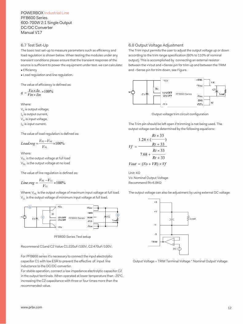
6.7 Test Set-UpThe basic test set-up to measure parameters such as efficiency and load regulation is shown below. When testing the modules under any transient conditions please ensure that the transient response of the source is sufficient to power the equipment under test. we can calculate:• Efficiency• Load regulation and line regulation.
The value of efficiency is defined as:
Where:Vo is output voltage, Io is output current, Vin is input voltage, Iin is input current.
The value of load regulation is defined as:
Where:VFL is the output voltage at full load VNL is the output voltage at no load
The value of line regulation is defined as:
Where: VHL is the output voltage of maximum input voltage at full load. VLL is the output voltage of minimum input voltage at full load.
PFB600 Series Test setup
Recommend C1and C2 Value C1:220uF/100V, C2:470uF/100V.
For PFB600 series it’s necessary to connect the input electrolytic capacitor C1 with low ESR to prevent the effective of input line inductance to the DC/DC converter.For stable operation, connect a low impedance electrolytic capacitor C2 in the output terminals. When operated at lower temperature than -20°C, increasing the C2 capacitance with three or four times more than the recommended value.
6.8 Output Voltage AdjustmentThe Trim input permits the user to adjust the output voltage up or down according to the trim range specification (60% to 110% of nominal output). This is accomplished by connecting an external resistor between the +Vout and +Sense pin for trim up and between the TRIM and –Sense pin for trim down, see Figure.
Output voltage trim circuit configuration
The Trim pin should be left open if trimming is not being used. The output voltage can be determined by the following equations:
Unit: KΩVo: Nominal Output VoltageRecommend Rt=6.8KΩ
The output voltage can also be adjustment by using external DC voltage
Output Voltage = TRIM Terminal Voltage * Nominal Output Voltage
η = Vo × Io Vin × Iin
×100%
Load.reg = VFL −VNL
×100% VNL
PFB600 Series
Line.reg = VHL −VLL
×100% VLL
PFB600 Series
Rt × 33
Vf =
1.24 × (
7.68 +
) Rt + 33 Rt × 33
Rt + 33 Vout = (Vo + VR) × Vf

13www.prbx.com
POWERBOX Industrial LinePFB600 Series600-700W 2:1 Single OutputDC/DC ConverterManual V17
6.9 Output Remote SensingThe PFB600 Series converter has the capability to remotely sense both lines of its output. This feature moves the effective output voltage regulation point from the output of the unit to the point of connection of the remote sense pins. This feature automatically adjusts the real output voltage of the PFB600 series in order to compensate for voltage drops in distribution and maintain a regulated voltage at the point of load. The remote-sense voltage range is: [(+Vout) - (-Vout)] – [(+Sense) – (-Sense)] < 10% of Vo_nominal
If the remote sense feature is not to be used, the sense pins should be connected locally. The +Sense pin should be connected to the +Vout pin at the module and the -Sense pin should be connected to the -Vout pin at the module. This is shown in the schematic below.
Note: Although the output voltage can be increased by increase for the output voltage is not the sum of both. The maximum increase is the larger of either the remote sense or the trim. The amount of power delivered by the module is defined as the voltage at the output terminals multiplied by the output current. When using remote sense and trim, the output voltage of the module can be increased and consequently increase the power output of the module if output current remains unchanged. Care should be taken to ensure that the maximum output power of the module remains at or below the maximum rated power (Maximum rated power = Vo,set x Io,max).
6.10 Output Ripple and Noise
Output ripple and noise is measured with 1.0uF ceramic and 10uF solid tantalum capacitors across the output.
6.11 Output CapacitanceThe PFB600 series converters provide unconditional stability with or without external capacitors. For good transient response, low ESR output capacitors should be located close to the point of load. PCB design
emphasizes low resistance and inductance tracks in consideration of high current applications. Output capacitors with their associated ESR values have an impact on loop stability and bandwidth. The minimum output capacitance is 470uF which need three or four times capacitance when operating below -20 and the absolute maximum value of PFB600 series’ output capacitance is 10000uF.For values larger than this, please contact your local Powerbox representative.
6.12 Parallel OperationThe PFB600 series are also designed for parallel operation. When paralleled, the load current can be equally shared between the modules by connecting the PC pins together.There are two different parallel operations for PFB600 series, one is parallel operation when load can’t be supplied by only one power unit; the other is the N+1 redundant operation which is high reliable for load of N units by using N+1 units.
(a) Parallel operation
(b) Parallel operation with programmed and adjustable output
PFB600 Series
PFB600 Series
+Vin +Vout
+SNS
+ON/OFF TRIM -ON/OFF
-SNS
-Vin -Vout
1uF
Load R1
DC C2C1 10uF
BNC to scope
L O A D
+S +V
-S PC
+S +V
-V -S PC
14www.prbx.com
POWERBOX Industrial LinePFB600 Series600-700W 2:1 Single OutputDC/DC ConverterManual V17
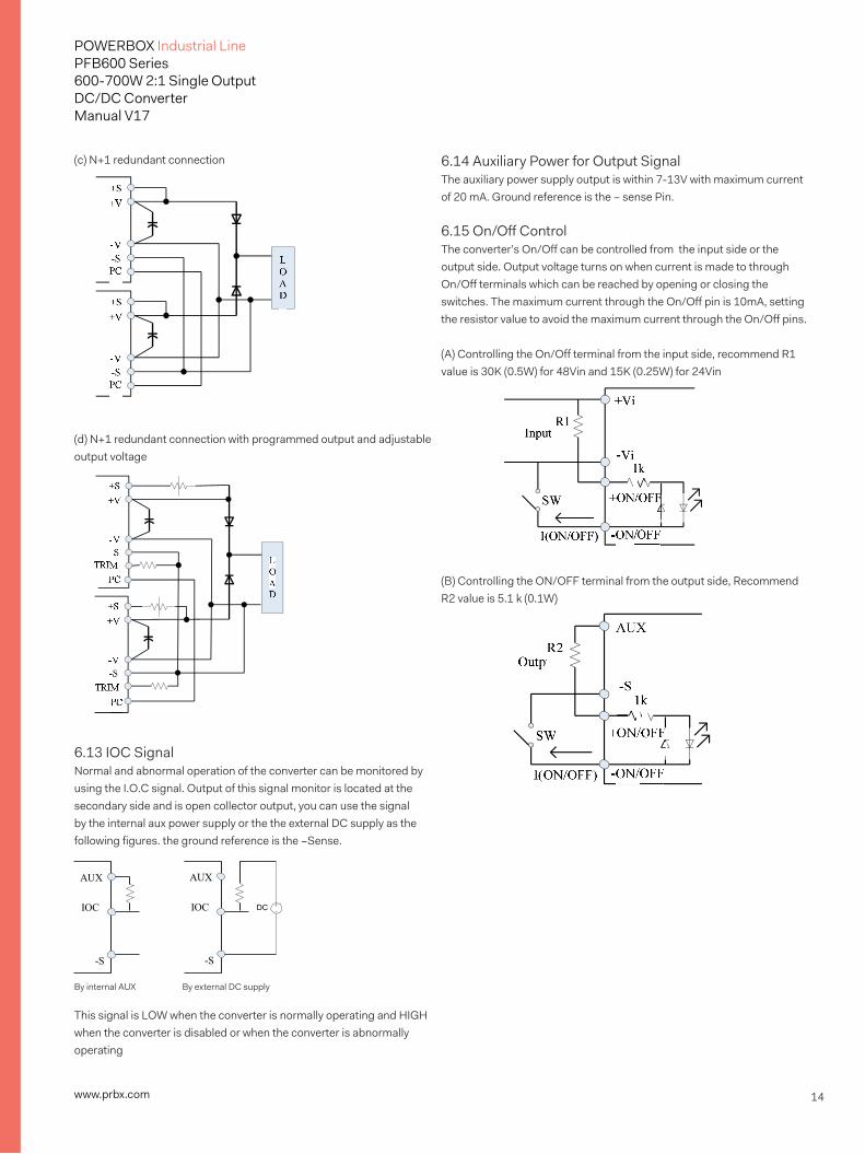
(c) N+1 redundant connection
(d) N+1 redundant connection with programmed output and adjustable output voltage
6.13 IOC SignalNormal and abnormal operation of the converter can be monitored by using the I.O.C signal. Output of this signal monitor is located at the secondary side and is open collector output, you can use the signal by the internal aux power supply or the the external DC supply as the following figures. the ground reference is the –Sense.
This signal is LOW when the converter is normally operating and HIGH when the converter is disabled or when the converter is abnormally operating
AUX
IOC
-S
AUX
IOC DC
-S
By internal AUX By external DC supply
6.14 Auxiliary Power for Output SignalThe auxiliary power supply output is within 7-13V with maximum current of 20 mA. Ground reference is the – sense Pin.
6.15 On/Off ControlThe converter’s On/Off can be controlled from the input side or the output side. Output voltage turns on when current is made to through On/Off terminals which can be reached by opening or closing the switches. The maximum current through the On/Off pin is 10mA, setting the resistor value to avoid the maximum current through the On/Off pins.
(A) Controlling the On/Off terminal from the input side, recommend R1 value is 30K (0.5W) for 48Vin and 15K (0.25W) for 24Vin
(B) Controlling the ON/OFF terminal from the output side, Recommend R2 value is 5.1 k (0.1W)
15www.prbx.com
POWERBOX Industrial LinePFB600 Series600-700W 2:1 Single OutputDC/DC ConverterManual V17
7. Safety & EMC
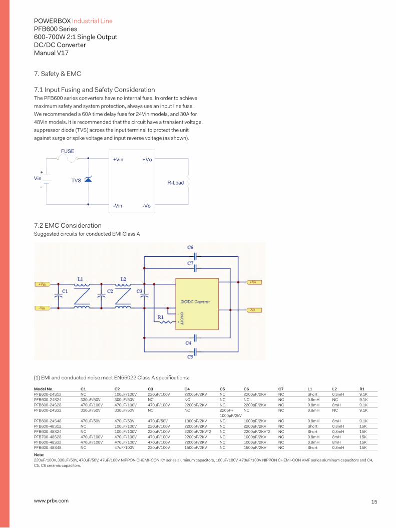
7.1 Input Fusing and Safety ConsiderationThe PFB600 series converters have no internal fuse. In order to achieve maximum safety and system protection, always use an input line fuse. We recommended a 60A time delay fuse for 24Vin models, and 30A for 48Vin models. It is recommended that the circuit have a transient voltage suppressor diode (TVS) across the input terminal to protect the unit against surge or spike voltage and input reverse voltage (as shown).
7.2 EMC ConsiderationSuggested circuits for conducted EMI Class A
(1) EMI and conducted noise meet EN55022 Class A specifications:
+Vin +Vo
-Vin -Vo
FUSE
+ Vin
- TVS R-Load
Model No. C1 C2 C3 C4 C5 C6 C7 L1 L2 R1PFB600-24S12 NC 100uF/100V 220uF/100V 2200pF/2KV NC 2200pF/2KV NC Short 0.8mH 9.1KPFB600-24S24 330uF/50V 300uF/50V NC NC NC NC NC 0.8mH NC 9.1KPFB600-24S28 470uF/100V 470uF/100V 470uF/100V 2200pF/2KV NC 2200pF/2KV NC 0.8mH 8mH 9.1KPFB600-24S32 330uF/50V 330uF/50V NC NC 220pF+ NC NC 0.8mH NC 9.1K 1000pF/2kVPFB600-24S48 470uF/50V 470uF/50V 470uF/50V 1000pF/2KV NC 1000pF/2KV NC 0.8mH 8mH 9.1KPFB600-48S12 NC 100uF/100V 220uF/100V 2200pF/2KV NC 2200pF/2KV NC Short 0.8mH 15KPFB600-48S24 NC 100uF/100V 220uF/100V 2200pF/2KV*2 NC 2200pF/2KV*2 NC Short 0.8mH 15KPFB700-48S28 470uF/100V 470uF/100V 470uF/100V 2200pF/2KV NC 1000pF/2KV NC 0.8mH 8mH 15KPFB600-48S32 470uF/100V 470uF/100V 470uF/100V 2200pF/2KV NC 1000pF/2KV NC 0.8mH 8mH 15KPFB600-48S48 NC 47uF/100V 220uF/100V 1500pF/2KV NC 1500pF/2KV NC Short 0.8mH 15K
Note: 220uF/100V, 330uF/50V, 470uF/50V, 47uF/100V NIPPON CHEMI-CON KY series aluminum capacitors, 100uF/100V, 470uF/100V NIPPON CHEMI-CON KMF series aluminum capacitors and C4, C5, C6 ceramic capacitors.
16www.prbx.com
POWERBOX Industrial LinePFB600 Series600-700W 2:1 Single OutputDC/DC ConverterManual V17
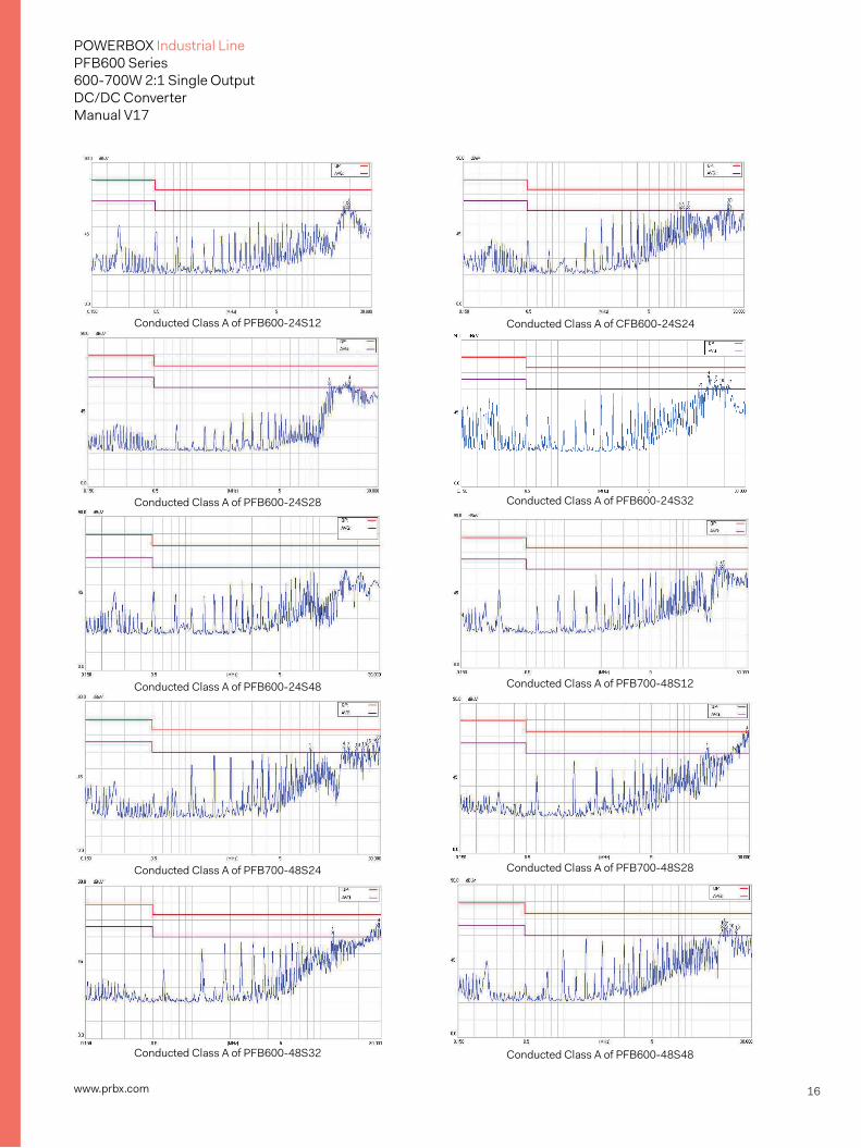
Conducted Class A of PFB600-24S12 Conducted Class A of CFB600-24S24
Conducted Class A of PFB600-24S28 Conducted Class A of PFB600-24S32
Conducted Class A of PFB600-24S48 Conducted Class A of PFB700-48S12
Conducted Class A of PFB700-48S24 Conducted Class A of PFB700-48S28
Conducted Class A of PFB600-48S32 Conducted Class A of PFB600-48S48
17www.prbx.com
POWERBOX Industrial LinePFB600 Series600-700W 2:1 Single OutputDC/DC ConverterManual V17
www.prbx.com 2016.03.04
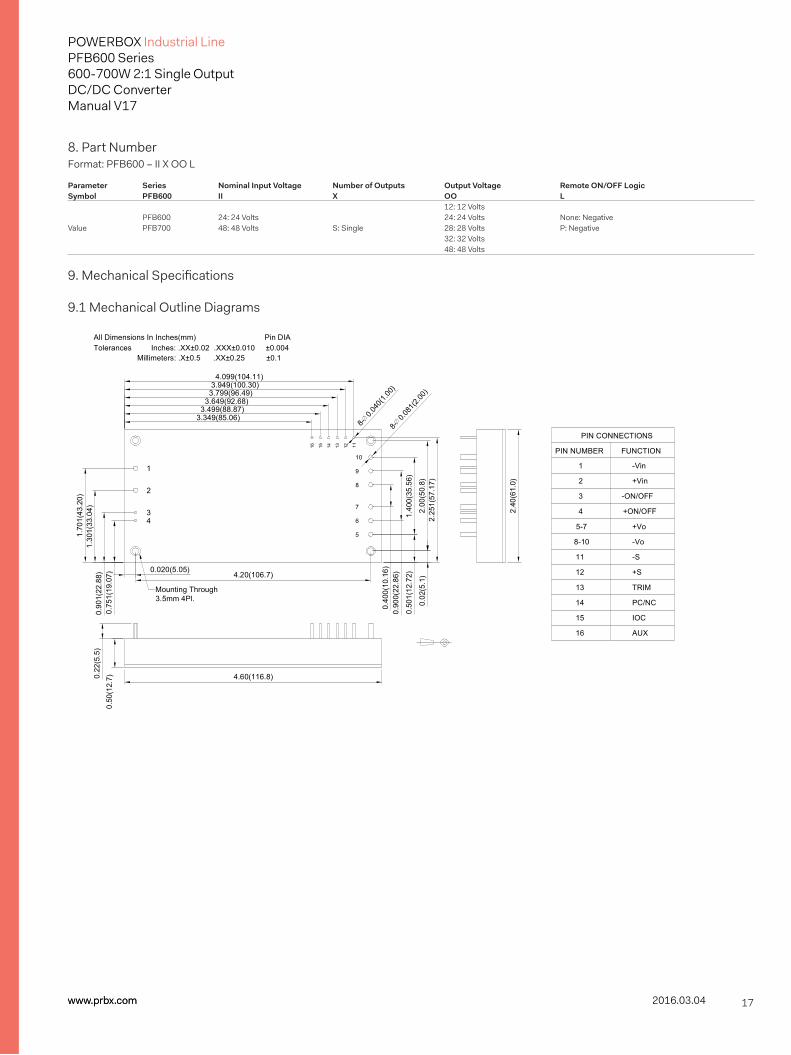
8. Part NumberFormat: PFB600 – II X OO L
Parameter Series Nominal Input Voltage Number of Outputs Output Voltage Remote ON/OFF Logic Symbol PFB600 II X OO L 12: 12 Volts PFB600 24: 24 Volts 24: 24 Volts None: Negative Value PFB700 48: 48 Volts S: Single 28: 28 Volts P: Negative 32: 32 Volts 48: 48 Volts
9. Mechanical Specifications
9.1 Mechanical Outline Diagrams
Mounting Through3.5mm 4Pl.
8-0.0
81(2.
00)
8-0.0
40(1.
00)
Tolerances Inches: .XX±0.02 .XXX±0.010 ±0.004 Millimeters: .X±0.5 .XX±0.25 ±0.1
All Dimensions In Inches(mm) Pin DIA
0.50
1(12
.72)
3.949(100.30)3.799(96.49)
3.649(92.68)3.499(88.87)
3.349(85.06)
1.70
1(43
.20)
1.30
1(33
.04)
0.90
1(22
.88)
0.75
1(19
.07)
0.020(5.05)
2.25
1(57
.17)
0.02
(5.1
)
1.40
0(35
.56)
0.90
0(22
.86)
0.40
0(10
.16)
2.40
(61.
0)
2.00
(50.
8)
4.20(106.7)
0.22
(5.5
)0.
50(1
2.7) 4.60(116.8)
TRIM
PC/NC
AUX
IOC
16
15
13
14
-Vin
+Vin
+ON/OFF
-ON/OFF
-S
+S
-Vo
+Vo5-7
8-10
12
11
3
4
2
1
PIN NUMBER
111214 131516
5
6
7
8
9
10
43
2
1
4.099(104.11)
PIN CONNECTIONS
FUNCTION