powermax1000 - jdzj.com · no. 19 kaki bukit road 2 ... mishima city, shizuoka pref. 411-0801 japan...
TRANSCRIPT

�
�
�
�15-25 ft4.5-7.5 m
35-50 ft12-15 m
6.0 BAR5.0
4.0 PSI8070
50 60
80
AMPS
120926 120925120978
120927120928
120928
120929
120977
110378 Rev. A
6.0BAR
5.04.0
PSI8070
50 60
60
40
AMPS
80
25
AC
+
_
�
�
��
�
�15-50 ft4.5-15 m
15-25 ft4.5-7.5 m
35-50 ft12-15 m
6.0 BAR5.04.0PSI807050 60
80
AMPS
80
AMPS
Plasma ArcCutting System
Operator Manual
804290 Revision 0
powermax1000®

Operator Manual
(P/N 804290)
Revision 0 – September 2001
Hypertherm, Inc.Hanover, NH USA
www.hypertherm.com
© Copyright 2001 Hypertherm, Inc.All Rights Reserved
Hypertherm and powermax are trademarks of Hypertherm, Inc. and may be registered in the United States and/or other countries.
powermax1000

Hypertherm, Inc.Etna Road, P.O. Box 5010Hanover, NH 03755 USA603-643-3441 Tel (Main Office)603-643-5352 Fax (All Departments)800-643-9878 Tel (Technical Service)800-737-2978 Tel (Customer Service)
Hypertherm Automation5 Technology DriveWest Lebanon, NH 03755 USA603-298-7970 Tel 603-298-7977 Fax
Hypertherm Plasmatechnik GmbHTechnologiepark HanauRodenbacher Chaussee 6 63457 Hanau-Wolfgang, Germany49 6181 58 2100 Tel 49 6181 58 2134 Fax49 6181 58 2123 (Technical Service)
Hypertherm Singapore Pte LtdNo. 19 Kaki Bukit Road 2 K.B. Warehouse Complex Singapore 417847, Republic of Singapore65 841 2489 Tel 65 841 2490 Fax 65 841 2489 (Technical Service)
Japan1952-14 Yata-NatsumegiMishima City, Shizuoka Pref.411-0801 Japan81 0 559 75 7387 Tel81 0 559 75 7376 Fax
Hypertherm UK Ltd9 Berkeley Court, Manor Park Runcorn, Cheshire, England WA7 1TQ44 1928 579 074 Tel 44 1928 579 604 Fax
France15 Impasse des Rosiers95610 Eragny, France0805 050 111 Tel 0805 050 222 Fax
Hypertherm S.r.L.Via Torino 220123 Milano, Italia39 02 725 46 312 Tel 39 02 725 46 400 Fax39 02 725 46 314 (Technical Service)
Hypertherm B.V.Burg. Haverkampstraat 13 7091 CN Dinxperlo, Nederland31 315 655866 Tel 31 315 655886 Fax
Hypertherm B.V. (ETSO)Vaartveld 94704 SE Roosendaal, Nederland00 800 49 73 7843 – toll-free in Europa 31 165 596900 Tel31 165 596901 Fax
Hypertherm Brasil Ltda.Rua Visconde de Santa Isabel, 20 – Sala 611Vila Isabel, RJ Brasil CEP 20560-12055 21 2278 6162 Tel55 21 2578 0947 Fax 10/30/01

ELECTROMAGNETIC COMPATIBILITY (EMC)
Hypertherm Plasma Systems i
EMC INTRODUCTION
Hypertherm's CE-marked equipment is builtin compliance with standard EN50199. Theequipment should be installed and used inaccordance with the information below toachieve electromagnetic compatibility.
The limits required by EN50199 may not beadequate to completely eliminate interfer-ence when the affected equipment is inclose proximity or has a high degree of sen-sitivity. In such cases it may be necessary to use other measures to further reduceinterference.
This plasma equipment is designed for useonly in an industrial environment.
INSTALLATION AND USE
The user is responsible for installing andusing the plasma equipment according tothe manufacturer's instructions. If electro-magnetic disturbances are detected then itshall be the responsibility of the user to re-solve the situation with the technical assis-tance of the manufacturer. In some casesthis remedial action may be as simple asearthing the cutting circuit, see Earthing ofWorkpiece. In other cases it could involveconstructing an electromagnetic screenenclosing the power source and the workcomplete with associated input filters. In allcases electromagnetic disturbances mustbe reduced to the point where they are nolonger troublesome.
ASSESSMENT OF AREA
Before installing the equipment the usershall make an assessment of potentialelectromagnetic problems in the surround-ing area. The following shall be taken intoaccount:a. Other supply cables, control cables, sig-nalling and telephone cables; above, belowand adjacent to the cutting equipment.b. Radio and television transmitters andreceivers.c. Computer and other control equipment.d. Safety critical equipment, for exampleguarding of industrial equipment.e. Health of the people around, for examplethe use of pacemakers and hearing aids.f. Equipment used for calibration or mea-surement.g. Immunity of other equipment in the en-vironment. User shall ensure that otherequipment being used in the environment iscompatible. This may require additional pro-tection measures.
h. Time of day that cutting or other activi-ties are to be carried out.
The size of the surrounding area to be con-sidered will depend on the structure of thebuilding and other activities that are takingplace. The surrounding area may extendbeyond the boundaries of the premises.
METHODS OF REDUCING EMISSIONS
Mains Supply
Cutting equipment must be connected tothe mains supply according to the manufac-turer's recommendations. If interferenceoccurs, it may be necessary to take addi-tional precautions such as filtering of themains supply. Consideration should begiven to shielding the supply cable of per-manently installed cutting equipment, inmetallic conduit or equivalent. Shieldingshould be electrically continuous through-out its length. The shielding should be con-nected to the cutting mains supply so thatgood electrical contact is maintained be-tween the conduit and the cutting powersource enclosure.
Maintenance of Cutting Equipment
The cutting equipment must be routinelymaintained according to the manufacturer'srecommendations. All access and servicedoors and covers should be closed andproperly fastened when the cutting equip-ment is in operation. The cutting equipmentshould not be modified in any way except forthose changes and adjustments covered inthe manufacturer's instructions. In particu-lar, the spark gaps of arc striking and stabi-lizing devices should be adjusted andmaintained according to the manufacturer'srecommendations.
Cutting Cables
The cutting cables should be kept as shortas possible and should be positioned closetogether, running at or close to the floorlevel.
Equipotential Bonding
Bonding of all metallic components in thecutting installation and adjacent to it shouldbe considered. However, metallic compo-nents bonded to the workpiece will increasethe risk that the operator could receive ashock by touching these metallic compo-
nents and the electrode at the same time.The operator should be insulated from allsuch bonded metallic components.
Earthing of Workpiece
Where the workpiece is not bonded to earthfor electrical safety, nor connected to earthbecause of its size and position, for exam-ple, ship's hull or building steelwork, a con-nection bonding the workpiece to earth mayreduce emissions in some, but not allinstances. Care should be taken to preventthe earthing of the workpiece increasing therisk of injury to users, or damage to otherelectrical equipment. Where necessary, theconnection of the workpiece to earth shouldbe made by a direct connection to the work-piece, but in some countries where directconnection is not permitted, the bondingshould be achieved by suitable capacitancesselected according to national regulations.
Note. The cutting circuit may or may not beearthed for safety reasons. Changing theearthing arrangements should only be au-thorized by a person who is competent toassess whether the changes will increasethe risk of injury, for example, by allowingparallel cutting current return paths whichmay damage the earth circuits of otherequipment. Further guidance is given in IECTC26 (sec)94 and IEC TC26/108A/CD ArcWelding Equipment Installation and Use.
Screening and Shielding
Selective screening and shielding of othercables and equipment in the surroundingarea may alleviate problems of interference.Screening of the entire plasma cuttinginstallation may be considered for specialapplications

WARRANTY
9-01
ii Hypertherm Plasma Systems
WARNINGGenuine Hypertherm parts are the factory-recommendedreplacement parts for your Hypertherm system. Anydamage caused by the use of other than genuineHypertherm parts may not be covered by the Hyperthermwarranty.
WARNINGYou are responsible for the safe use of the Product.Hypertherm does not and cannot make any guarantee orwarranty regarding the safe use of the Product in yourenvironment.
GENERALHypertherm, Inc. warrants that its Products shall be free from defects in materials and workmanship, ifHypertherm is notified of a defect (i) with respect to thepower supply within a period of two (2) years from the dateof its delivery to you, with the exception of G3 Series powersupplies, which shall be within a period of three (3) yearsfrom the date of delivery to you, and (ii) with respect to thetorch and leads within a period of one (1) year from its dateof delivery to you. This warranty shall not apply to anyProduct which has been incorrectly installed, modified, orotherwise damaged. Hypertherm, at its sole option, shallrepair, replace, or adjust, free of charge, any defectiveProducts covered by this warranty which shall be returnedwith Hypertherm’s prior authorization (which shall not beunreasonably withheld), properly packed, to Hypertherm’splace of business in Hanover, New Hampshire, or to anauthorized Hypertherm repair facility, all costs, insuranceand freight prepaid. Hypertherm shall not be liable for anyrepairs, replacement, or adjustments of Products coveredby this warranty, except those made pursuant to thisparagraph or with Hypertherm’s prior written consent. Thewarranty above is exclusive and is in lieu of all otherwarranties, express, implied, statutory, or otherwisewith respect to the Products or as to the results whichmay be obtained therefrom, and all implied warrantiesor conditions of quality or of merchantability or fitnessfor a particular purpose or against infringement. Theforegoing shall constitute the sole and exclusiveremedy for any breach by Hypertherm of its warranty.Distributors/OEMs may offer different or additionalwarranties, but Distributors/OEMs are not authorized togive any additional warranty protection to you or make anyrepresentation to you purporting to be binding uponHypertherm.
PATENT INDEMNITYExcept only in cases of products not manufactured byHypertherm or manufactured by a person other thanHypertherm not in strict conformity with Hypertherm’sspecifications and in cases of designs, processes,
formulae, or combinations not developed or purported to be developed by Hypertherm, Hypertherm will defend orsettle, at its own expense, any suit or proceeding broughtagainst you alleging that the use of the Hyperthermproduct, alone and not in combination with any otherproduct not supplied by Hypertherm, infringes any patentof any third party. You shall notify Hypertherm promptlyupon learning of any action or threatened action inconnection with any such alleged infringement, andHypertherm’s obligation to indemnify shall be conditionedupon Hypertherm’s sole control of, and the indemnifiedparty’s cooperation and assistance in, the defense of the claim.
LIMITATION OF LIABILITYIn no event shall Hypertherm be liable to any personor entity for any incidental, consequential, indirect, orpunitive damages (including but not limited to lostprofits) regardless of whether such liability is basedon breach of contract, tort, strict liability, breach ofwarranties, failure of essential purpose or otherwiseand even if advised of the possibility of such damages.
LIABILITY CAPIn no event shall Hypertherm’s liability, whether suchliability is based on breach of contract, tort, strictliability, breach of warranties, failure of essentialpurpose or otherwise, for any claim action suit orproceeding arising out of or relating to the use of theProducts exceed in the aggregate the amount paid forthe Products that gave rise to such claim.
INSURANCEAt all times you will have and maintain insurance in suchquantities and types, and with coverage sufficient andappropriate to defend and to hold Hypertherm harmless inthe event of any cause of action arising from the use of theProducts.
NATIONAL AND LOCAL CODESNational and Local codes governing plumbing andelectrical installation shall take precedent over anyinstructions contained in this manual. In no event shallHypertherm be liable for injury to persons or propertydamage by reason of any code violation or poor workpractices.
TRANSFER OF RIGHTSYou may transfer any remaining rights you may havehereunder only in connection with the sale of all orsubstantially all of your assets or capital stock to asuccessor in interest who agrees to be bound by all of theterms and conditions of this Warranty.

TABLE OF CONTENTS
0
powermax1000 Operator Manual iii
Electromagnetic Compatibility .......................................................................................................................iWarranty .......................................................................................................................................................ii
Section 1 SafetyRecognize Safety Information ...................................................................................................................1-2Follow Safety Instructions .........................................................................................................................1-2Cutting Can Cause Fire or Explosion........................................................................................................1-2Electric Shock Can Kill ..............................................................................................................................1-3Cutting Can Produce Toxic Fumes............................................................................................................1-3A Plasma Arc Can Cause Injury and Burns...............................................................................................1-4Arc Rays Can Burn Eyes and Skin ...........................................................................................................1-4Grounding Safety ......................................................................................................................................1-4Compressed Gas Equipment Safety.........................................................................................................1-5Gas Cylinders Can Explode If Damaged ..................................................................................................1-5Noise Can Damage Hearing .....................................................................................................................1-5Pacemaker and Hearing Aid Operation.....................................................................................................1-5A Plasma Arc Can Damage Frozen Pipes ................................................................................................1-5Additional Safety Information ....................................................................................................................1-5Warning Label ...........................................................................................................................................1-6
Section 1a SécuritéIdentifier les consignes de sécurité .........................................................................................................1a-2Suivre les instructions de sécurité...........................................................................................................1a-2Danger Avertissement Précaution.........................................................................................................1a-2Le coupage peut provoquer un incendie ou une explosion.....................................................................1a-2
Prévention des incendies, Prévention des explosions ..................................................................1a-2Risque d’explosion argon-hydrogène et méthane .........................................................................1a-2Détonation de l’hydrogène lors du coupage de l’aluminium ..........................................................1a-2
Les chocs électriques peuvent être fatals ...............................................................................................1a-3Prévention des chocs électriques..................................................................................................1a-3
Le coupage peut produire des vapeurs toxiques ....................................................................................1a-3L’arc plasma peut provoquer des blessures ou des brûlures..................................................................1a-4
Torches à allumage instantané......................................................................................................1a-4Les rayons de l’arc peuvent brûler les yeux et la peau ...........................................................................1a-4
Protection des yeux, Protection de la peau, Zone de coupage ...................................................1a-4Mise à la masse et à la terre ...................................................................................................................1a-4
Câble de retour, Table de travail, Alimentation ..............................................................................1a-4Sécurité des bouteilles de gaz comprimé ...............................................................................................1a-5Les bouteilles de gaz comprimé peuvent exploser en cas de dommages..............................................1a-5Le bruit peut provoquer des problèmes auditifs ......................................................................................1a-5Pacemakers et prothèses auditives ........................................................................................................1a-5Un arc plasma peut endommager les tuyaux gelés ................................................................................1a-5Étiquette de sécurité ...............................................................................................................................1a-6
Section 2 SpecificationsSpecifications – Power Supply .................................................................................................................2-2
Power Supply – Dimensions and Weight.........................................................................................2-3Specifications – T60 Torches ...................................................................................................................2-4

TABLE OF CONTENTS
0
iv powermax1000 Operator Manual
Torch Dimensions......................................................................................................................................2-5Symbols and Markings..............................................................................................................................2-6
Section 3 SetupUpon Receipt ............................................................................................................................................3-2Claims .......................................................................................................................................................3-2Contents of Box.........................................................................................................................................3-2Locating Power Supply .............................................................................................................................3-2Lifting Power Supply .................................................................................................................................3-3Power Connection.....................................................................................................................................3-4Three Phase Power Cord – Plug Installation ............................................................................................3-4Single Phase Power Cord .........................................................................................................................3-5
Power Cord Installation ...................................................................................................................3-5Plug Installation ...............................................................................................................................3-5
Grounding ................................................................................................................................................3-6Extension Cords........................................................................................................................................3-6Torch Installation .......................................................................................................................................3-7Plasma Gas Supply ..................................................................................................................................3-9
Additional Gas Filtration ..................................................................................................................3-9Gas Supply Installation ...........................................................................................................................3-10T60M Torch Alignment.............................................................................................................................3-10
ON/OFF Pendant Connection........................................................................................................3-11Machine Interface Connection .......................................................................................................3-11Arc Voltage ....................................................................................................................................3-12
Changing XFER (start machine motion) from dry contact closure to voltage signal ...............................3-14
Section 4 OperationControls and Indicators .............................................................................................................................4-2
Indicator LEDs .................................................................................................................................4-2Torch Consumable Configurations ............................................................................................................4-3Installing Torch Consumables ...................................................................................................................4-4Mode Switch..............................................................................................................................................4-5Turn Power ON .........................................................................................................................................4-5Check Indicator Lights...............................................................................................................................4-5Adjust Gas Pressure and Current Setting .................................................................................................4-6Hand Torch Operation ...............................................................................................................................4-7
Safety Trigger Operation .................................................................................................................4-7Attach the Work Clamp....................................................................................................................4-8Starting a Cut from the Edge of the Workpiece ...............................................................................4-8Hand Torch Cutting Technique.........................................................................................................4-9Piercing..........................................................................................................................................4-10Gouging .........................................................................................................................................4-11
Cut Charts ...............................................................................................................................................4-12
Section 5 Maintenance and PartsRoutine Maintenance ................................................................................................................................5-2Inspect Consumables................................................................................................................................5-3

TABLE OF CONTENTS
0
powermax1000 Operator Manual v
Controls and Indicators .............................................................................................................................5-4Basic Troubleshooting...............................................................................................................................5-5System Circuit Diagram ............................................................................................................................5-8Technical Questions ..................................................................................................................................5-9Parts........................................................................................................................................................5-10
Torch Consumable Configurations ................................................................................................5-10Torch Parts.....................................................................................................................................5-11Power Supply Parts .......................................................................................................................5-11Accessories ...................................................................................................................................5-12

Hypertherm Plasma Systems 1-1
Section 1
SAFETY
In this section:
Recognize Safety Information ...................................................................................................................1-2Follow Safety Instructions .........................................................................................................................1-2Cutting Can Cause Fire or Explosion........................................................................................................1-2Electric Shock Can Kill ..............................................................................................................................1-3Cutting Can Produce Toxic Fumes............................................................................................................1-3A Plasma Arc Can Cause Injury and Burns...............................................................................................1-4Arc Rays Can Burn Eyes and Skin ...........................................................................................................1-4Grounding Safety ......................................................................................................................................1-4Compressed Gas Equipment Safety.........................................................................................................1-5Gas Cylinders Can Explode If Damaged ..................................................................................................1-5Noise Can Damage Hearing .....................................................................................................................1-5Pacemaker and Hearing Aid Operation.....................................................................................................1-5A Plasma Arc Can Damage Frozen Pipes ................................................................................................1-5Additional Safety Information ....................................................................................................................1-5Warning Label ...........................................................................................................................................1-6

SAFETY
11-98
1-2 Hypertherm Plasma Systems
RECOGNIZE SAFETY INFORMATION
The symbols shown in this section are used toidentify potential hazards. When you see a safetysymbol in this manual or on your machine,understand the potential for personal injury, andfollow the related instructions to avoid the hazard.
FOLLOW SAFETY INSTRUCTIONS
Read carefully all safety messages in this manualand safety labels on your machine.
• Keep the safety labels on your machine in goodcondition. Replace missing or damaged labelsimmediately.
• Learn how to operate the machine and how to usethe controls properly. Do not let anyone operate itwithout instruction.
• Keep your machine in proper working condition.Unauthorized modifications to the machine mayaffect safety and machine service life.
DANGER WARNING CAUTION
A signal word DANGER or WARNING is used with asafety symbol. DANGER identifies the most serioushazards.
• DANGER and WARNING safety labels are locatedon your machine near specific hazards.
• WARNING safety messages precede relatedinstructions in this manual that may result in injuryor death if not followed correctly.
• CAUTION safety messages precede relatedinstructions in this manual that may result indamage to equipment if not followed correctly.
Fire Prevention• Be sure the area is safe before doing any cutting.
Keep a fire extinguisher nearby.• Remove all flammables within 35 feet (10 m) of the
cutting area.• Quench hot metal or allow it to cool before handling
or before letting it touch combustible materials.• Never cut containers with potentially flammable
materials inside – they must be emptied andproperly cleaned first.
• Ventilate potentially flammable atmospheres beforecutting.
• When cutting with oxygen as the plasma gas, anexhaust ventilation system is required.
Explosion Prevention• Do not use the plasma system if explosive dust or
vapors may be present.• Do not cut pressurized cylinders, pipes, or any
closed container.• Do not cut containers that have held combustible
materials.
CUTTING CAN CAUSE FIRE OR EXPLOSION
WARNING
Explosion HazardArgon-Hydrogen and Methane
Hydrogen and methane are flammable gases thatpresent an explosion hazard. Keep flames away fromcylinders and hoses that contain methane or hydrogenmixtures. Keep flames and sparks away from the torchwhen using methane or argon-hydrogen plasma.
WARNING
Hydrogen Detonation with Aluminum Cutting
• When cutting aluminum underwater, or with thewater touching the underside of the aluminum, freehydrogen gas may collect under the workpiece anddetonate during plasma cutting operations.
• Install an aeration manifold on the floor of the watertable to eliminate the possibility of hydrogendetonation. Refer to the Appendix section of thismanual for aeration manifold details.

SAFETY
8-98
Hypertherm Plasma Systems 1-3
Touching live electrical parts can cause a fatal shockor severe burn.
• Operating the plasma system completes anelectrical circuit between the torch and theworkpiece. The workpiece and anything touchingthe workpiece are part of the electrical circuit.
• Never touch the torch body, workpiece or the waterin a water table when the plasma system isoperating.
Electric Shock Prevention
All Hypertherm plasma systems use high voltagein the cutting process (200 to 400 VDC arecommon). Take the following precautions whenoperating this system:• Wear insulated gloves and boots, and keep your
body and clothing dry.• Do not stand, sit or lie on – or touch – any wet
surface when using the plasma system.• Insulate yourself from work and ground using dry
insulating mats or covers big enough to prevent anyphysical contact with the work or ground. If youmust work in or near a damp area, use extremecaution.
• Provide a disconnect switch close to the powersupply with properly sized fuses. This switch allowsthe operator to turn off the power supply quickly inan emergency situation.
• When using a water table, be sure that it is correctlyconnected to earth ground.
ELECTRIC SHOCK CAN KILL
• Install and ground this equipment according to theinstruction manual and in accordance with nationaland local codes.
• Inspect the input power cord frequently for damageor cracking of the cover. Replace a damaged powercord immediately. Bare wiring can kill.
• Inspect and replace any worn or damaged torchleads.
• Do not pick up the workpiece, including the wastecutoff, while you cut. Leave the workpiece in placeor on the workbench with the work cable attachedduring the cutting process.
• Before checking, cleaning or changing torch parts,disconnect the main power or unplug the powersupply.
• Never bypass or shortcut the safety interlocks.• Before removing any power supply or system
enclosure cover, disconnect electrical input power.Wait 5 minutes after disconnecting the main powerto allow capacitors to discharge.
• Never operate the plasma system unless the powersupply covers are in place. Exposed power supplyconnections present a severe electrical hazard.
• When making input connections, attach propergrounding conductor first.
• Each Hypertherm plasma system is designed to beused only with specific Hypertherm torches. Do notsubstitute other torches which could overheat andpresent a safety hazard.
Cutting can produce toxic fumes and gases thatdeplete oxygen and cause injury or death.
• Keep the cutting area well ventilated or use anapproved air-supplied respirator.
• Do not cut in locations near degreasing, cleaning orspraying operations. The vapors from certainchlorinated solvents decompose to form phosgenegas when exposed to ultraviolet radiation.
• Do not cut metal coated or containing toxic materi-als, such as zinc (galvanized), lead, cadmium or
CUTTING CAN PRODUCE TOXIC FUMES
beryllium, unless the area is well ventilated and theoperator wears an air-supplied respirator. Thecoatings and any metals containing these elementscan produce toxic fumes when cut.
• Never cut containers with potentially toxic materialsinside – they must be emptied and properly cleanedfirst.
• This product, when used for welding or cutting,produces fumes or gases which contain chemicalsknown to the State of California to cause birthdefects and, in some cases, cancer.

SAFETY
4-99
1-4 Hypertherm Plasma Systems
Instant-On TorchesPlasma arc comes on immediately when the torchswitch is activated.
A PLASMA ARC CAN CAUSE INJURY AND BURNS
The plasma arc will cut quickly through gloves andskin.• Keep away from the torch tip.• Do not hold metal near the cutting path.• Never point the torch toward yourself or others.
Work Cable Attach the work cable securely to theworkpiece or the work table with good metal-to-metal contact. Do not connect it to the piece that willfall away when the cut is complete.
Work Table Connect the work table to an earthground, in accordance with appropriate national orlocal electrical codes.
GROUNDING SAFETY Input Power• Be sure to connect the power cord ground wire to
the ground in the disconnect box.• If installation of the plasma system involves
connecting the power cord to the power supply, besure to connect the power cord ground wireproperly.
• Place the power cord's ground wire on the studfirst, then place any other ground wires on top ofthe power cord ground. Fasten the retaining nuttightly.
• Tighten all electrical connections to avoidexcessive heating.
Eye Protection Plasma arc rays produce intensevisible and invisible (ultraviolet and infrared) raysthat can burn eyes and skin.• Use eye protection in accordance with applicable
national or local codes.• Wear eye protection (safety glasses or goggles
with side shields, or a welding helmet) withappropriate lens shading to protect your eyes fromthe arc’s ultraviolet and infrared rays.
Lens ShadeArc Current AWS (USA) ISO 4850
Up to 100 A No. 8 No. 11100-200 A No. 10 No. 11-12200-400 A No. 12 No. 13Over 400 A No. 14 No. 14
ARC RAYS CAN BURN EYES AND SKIN
Skin Protection Wear protective clothing to protectagainst burns caused by ultraviolet light, sparks andhot metal.• Gauntlet gloves, safety shoes and hat.• Flame-retardant clothing to cover all exposed
areas.• Cuffless trousers to prevent entry of sparks and
slag.• Remove any combustibles, such as a butane
lighter or matches, from your pockets beforecutting.
Cutting Area Prepare the cutting area to reducereflection and transmission of ultraviolet light:• Paint walls and other surfaces with dark colors to
reduce reflection. • Use protective screens or barriers to protect others
from flash and glare.• Warn others not to watch the arc. Use placards or
signs.

SAFETY
11-98
Hypertherm Plasma Systems 1-5
• Never lubricate cylinder valves or regulators withoil or grease.
• Use only correct gas cylinders, regulators, hosesand fittings designed for the specific application.
• Maintain all compressed gas equipment andassociated parts in good condition.
• Label and color-code all gas hoses to identify thetype of gas in each hose. Consult applicablenational or local codes.
GAS CYLINDERS CANEXPLODE IF DAMAGED
COMPRESSED GAS EQUIPMENT SAFETY
Gas cylinders contain gas under high pressure. Ifdamaged, a cylinder can explode.• Handle and use compressed gas cylinders in
accordance with applicable national or local codes.• Never use a cylinder that is not upright and
secured in place.• Keep the protective cap in place over valve except
when the cylinder is in use or connected for use.• Never allow electrical contact between the plasma
arc and a cylinder.• Never expose cylinders to excessive heat, sparks,
slag or open flame.• Never use a hammer, wrench or other tool to open
a stuck cylinder valve.
ADDITIONAL SAFETY INFORMATION1. ANSI Standard Z49.1, Safety in Welding and Cutting, American
Welding Society, 550 LeJeune RoadP.O. Box 351020, Miami, FL 33135
2. ANSI Standard Z49.2, Fire Prevention in the Use of Cutting andWelding Processes, American National Standards Institute1430 Broadway, New York, NY 10018
3. ANSI Standard Z87.1, Safe Practices for Occupation andEducational Eye and Face Protection, American National StandardsInstitute, 1430 Broadway, New York, NY 10018
4. AWS F4.1, Recommended Safe Practices for the Preparation forWelding and Cutting of Containers and Piping That Have HeldHazardous Substances, American Welding Society550 LeJeune Road, P.O. Box 351040, Miami, FL 33135
5. AWS F5.2, Recommended Safe Practices for Plasma Arc Cutting, American Welding Society550 LeJeune Road, P.O. Box 351040, Miami, FL 33135
6. CGA Pamphlet P-1, Safe Handling of Compressed Gases inCylinders, Compressed Gas Association1235 Jefferson Davis Highway, Arlington, VA 22202
7. CSA Standard W117.2, Code for Safety in Welding and Cutting,Canadian Standards Association Standard Sales178 Rexdale Boulevard, Rexdale, Ontario M9W 1R3, Canada
8. NFPA Standard 51B, Cutting and Welding Processes, National FireProtection Association470 Atlantic Avenue, Boston, MA 02210
9. NFPA Standard 70–1978, National Electrical Code, National FireProtection Association, 470 Atlantic Avenue, Boston, MA 02210
10. OSHA, Safety and Health Standards, 29FR 1910U.S. Government Printing Office, Washington, D.C. 20402
Prolonged exposure to noise from cutting orgouging can damage hearing.• Use approved ear protection when using plasma
system.• Warn others nearby about the noise hazard.
Frozen pipes may be damaged or can burst if youattempt to thaw them with a plasma torch.
NOISE CAN DAMAGE HEARING
A PLASMA ARC CANDAMAGE FROZEN PIPES
Pacemaker and hearing aid operation can beaffected by magnetic fields from high currents.Pacemaker and hearing aid wearers shouldconsult a doctor before going near any plasma arccutting and gouging operations.
To reduce magnetic field hazards:• Keep both the work cable and the torch lead to
one side, away from your body.• Route the torch leads as close as possible to the
work cable.• Do not wrap or drape the torch lead or work
cable around your body.• Keep as far away from the power supply as
possible.
PACEMAKER AND HEARINGAID OPERATION

SAFETY
8-01
1-6 Hypertherm Plasma Systems
WARNING LABELThis warning label is affixed to some power supplies. It isimportant that the operator and maintenance technicianunderstand the intent of these warning symbols as described.The numbered text corresponds to the numbered boxes onthe label.
1. Cutting sparks can cause explosion orfire.
1.1 Keep flammables away from cutting.
1.2 Keep a fire extinguisher nearby, andhave a watchperson ready to use it.
1.3 Do not cut on any closed containers.
2. The plasma arc can cause injury andburns.
2.1 Turn off power before disassemblingtorch.
2.2 Do not hold the material near cuttingpath.
2.3 Wear complete body protection.
3. Electric shock from torch or wiring cankill. Protect yourself from electric shock.
3.1 Wear insulating gloves. Do not wear wetor damaged gloves.
3.2 Insulate yourself from work and ground.
3.3 Disconnect input plug or power beforeworking on machine.
4. Breathing cutting fumes can behazardous to your health.
4.1 Keep your head out of the fumes.
4.2 Use forced ventilation or local exhaustto remove the fumes.
4.3 Use ventilating fan to remove the fumes.
5. Arc rays can burn eyes and injure skin.
5.1 Wear hat and safety glasses. Use earprotection and button shirt collar. Usewelding helmet with correct shade offilter. Wear complete body protection.
6. Become trained and read theinstructions before working on themachine or cutting.
7. Do not remove or paint over (cover)warning labels.
110212

2/12/01
Hypertherm Systèmes plasma 1a-1
Section 1a
SÉCURITÉ
Dans cette section :
Identifier les consignes de sécurité .........................................................................................................1a-2Suivre les instructions de sécurité...........................................................................................................1a-2Danger Avertissement Précaution.........................................................................................................1a-2Le coupage peut provoquer un incendie ou une explosion.....................................................................1a-2
Prévention des incendies, Prévention des explosions ..................................................................1a-2Risque d’explosion argon-hydrogène et méthane .........................................................................1a-2Détonation de l’hydrogène lors du coupage de l’aluminium ..........................................................1a-2
Les chocs électriques peuvent être fatals ...............................................................................................1a-3Prévention des chocs électriques..................................................................................................1a-3
Le coupage peut produire des vapeurs toxiques ....................................................................................1a-3L’arc plasma peut provoquer des blessures ou des brûlures..................................................................1a-4
Torches à allumage instantané......................................................................................................1a-4Les rayons de l’arc peuvent brûler les yeux et la peau ...........................................................................1a-4
Protection des yeux, Protection de la peau, Zone de coupage ...................................................1a-4Mise à la masse et à la terre ...................................................................................................................1a-4
Câble de retour, Table de travail, Alimentation ..............................................................................1a-4Sécurité des bouteilles de gaz comprimé ...............................................................................................1a-5Les bouteilles de gaz comprimé peuvent exploser en cas de dommages..............................................1a-5Le bruit peut provoquer des problèmes auditifs ......................................................................................1a-5Pacemakers et prothèses auditives ........................................................................................................1a-5Un arc plasma peut endommager les tuyaux gelés ................................................................................1a-5Étiquette de sécurité ...............................................................................................................................1a-6

SÉCURITÉ
2/12/01
1a-2 Hypertherm Systèmes plasma
IDENTIFIER LES CONSIGNES DE SÉCURITÉ
Les symboles indiqués dans cette section sont utiliséspour identifier les risques éventuels. Si vous trouvez unsymbole de sécurité, que ce soit dans ce manuel ou surl’équipement, soyez conscient des risques de blessures etsuivez les instructions correspondantes afin d’éviter cesrisques.
SUIVRE LES INSTRUCTIONS DE SÉCURITÉ
Lire attentivement toutes les consignes de sécurité dansle présent manuel et sur les étiquettes de sécurité setrouvant sur la machine.
• Les étiquettes de sécurité doivent rester lisibles.Remplacer immédiatement les étiquettes manquantesou abîmées.
• Apprendre à faire fonctionner la machine et à utilisercorrectement les commandes. Ne laisser personneutiliser la machine sans connaître son fonctionnement.
• Garder la machine en bon état. Des modifications nonautorisées sur la machine peuvent engendrer desproblèmes de sécurité et raccourcir la durée d’utilisationde l’équipement.
DANGER AVERTISSEMENT PRÉCAUTION
Les signaux DANGER ou AVERTISSEMENT sont utilisésavec un symbole de sécurité, DANGER correspondantaux risques les plus sérieux.• Les étiquettes de sécurité DANGER et AVERTISSE-
MENT sont situées sur la machine pour signaler certainsdangers spécifiques.
• Les messages d’AVERTISSEMENT précèdent lesinstructions d’utilisation expliquées dans ce manuel etsignalent les risques de blessures ou de mort au cas oùces instructions ne seraient pas suivies correctement.
• Les messages de PRÉCAUTION précèdent lesinstructions d’utilisation contenues dans ce manuel etsignalent que le matériel risque d’être endommagé si lesinstructions ne sont pas suivies correctement.
Prévention des incendies• Avant de commencer, s’assurer que la zone de coupage
ne présente aucun danger. Conserver un extincteur àproximité.
• Éloigner toute matière inflammable à une distance d’aumoins 10 m du poste de coupage.
• Tremper le métal chaud ou le laisser refroidir avant de le manipuler ou avant de le mettre en contact avec desmatériaux combustibles.
• Ne jamais couper des récipients pouvant contenir desmatières inflammables avant de les avoir vidés etnettoyés correctement.
• Aérer toute atmosphère potentiellement inflammableavant d’utiliser un système plasma.
• Lors de l’utilisation d’oxygène comme gaz plasma, unsystème de ventilation par aspiration est nécessaire.
Prévention des explosions• Ne pas couper en présence de poussière ou de
vapeurs.• Ne pas couper de bouteilles, de tuyaux ou autres
récipients fermés et pressurisés.• Ne pas couper de récipients contenant des matières
combustibles.
LE COUPAGE PEUT PROVOQUER UN INCENDIEOU UNE EXPLOSION
AVERTISSEMENT
Risque d’explosionargon-hydrogène et méthane
L’hydrogène et le méthane sont des gaz inflammables etpotentiellement explosifs. Conserver à l’écart de touteflamme les bouteilles et tuyaux contenant des mélanges àbase d’hydrogène ou de méthane. Maintenir toute flammeet étincelle à l’écart de la torche lors de l’utilisation d’unplasma d’argon-hydrogène ou de méthane.
AVERTISSEMENT
Détonation de l’hydrogène lors du coupage de l’aluminium
• Lors du coupage de l’aluminium sous l’eau, ou si l’eautouche la partie inférieure de la pièce d’aluminium, del’hydrogène libre peut s’accumuler sous la pièce àcouper et détonner lors du coupage plasma.
• Installer un collecteur d’aération au fond de la table à eauafin d’éliminer les risques de détonation de l’hydrogène.Se référer à l’annexe du manuel pour plus derenseignements sur les collecteurs d’aération.

SÉCURITÉ
2/12/01
Hypertherm Systèmes plasma 1a-3
Toucher une pièce électrique sous tension peut provoquerun choc électrique fatal ou des brûlures graves.• La mise en fonctionnement du système plasma ferme un
circuit électrique entre la torche et la pièce à couper. Lapièce à couper et tout autre élément en contact avec cettepièce font partie du circuit électrique.
• Ne jamais toucher le corps de la torche, la pièce à couperou l’eau de la table à eau pendant le fonctionnement dusystème plasma.
Prévention des chocs électriques
Tous les systèmes plasma Hypertherm utilisent deshautes tensions pour le coupage (souvent de 200 à 400V). On doit prendre les précautions suivantes quand onutilise le système plasma :• Porter des bottes et des gants isolants et garder le corps
et les vêtements au sec.• Ne pas se tenir, s’asseoir ou se coucher sur une surface
mouillée, ni la toucher quand on utilise le système plasma.• S’isoler de la surface de travail et du sol en utilisant des
tapis isolants secs ou des couvertures assez grandespour éviter tout contact physique avec le travail ou le sol.S’il s’avère nécessaire de travailler dans ou près d’unendroit humide, procéder avec une extrême prudence.
• Installer un sectionneur avec fusibles appropriés, àproximité de la source de courant. Ce dispositif permet àl’opérateur d’arrêter rapidement la source de courant encas d’urgence.
• En cas d’utilisation d’une table à eau, s’assurer que cettedernière est correctement mise à la terre.
LES CHOCS ÉLECTRIQUES PEUVENT ÊTRE FATALS
• Installer et mettre à la terre l’équipement selon lesinstructions du présent manuel et conformément auxcodes électriques locaux et nationaux.
• Inspecter fréquemment le cordon d’alimentation primairepour s’assurer qu’il n’est ni endommagé, ni fendu.Remplacer immédiatement un cordon endommagé. Un câble dénudé peut tuer.
• Inspecter et remplacer les câbles de la torche qui sontusés ou endommagés.
• Ne pas saisir la pièce à couper ni les chutes lors ducoupage. Laisser la pièce à couper en place ou sur latable de travail, le câble de retour connecté lors ducoupage.
• Avant de vérifier, de nettoyer ou de remplacer les piècesde la torche, couper l’alimentation ou débrancher la prisede courant.
• Ne jamais contourner ou court-circuiter les verrouillagesde sécurité.
• Avant d’enlever le capot du système ou de la source decourant, couper l’alimentation électrique. Attendre ensuite5 minutes pour que les condensateurs se déchargent.
• Ne jamais faire fonctionner le système plasma sans queles capots de la source de courant ne soient en place.Les raccords exposés de la source de courant sontextrêmement dangereux.
• Lors de l’installation des connexions, attacher tout d’abordla prise de terre appropriée.
• Chaque système plasma Hypertherm est conçu pour êtreutilisé uniquement avec des torches Hyperthermspécifiques. Ne pas utiliser des torches inappropriées quipourraient surchauffer et présenter des risques pour lasécurité.
Le coupage peut produire des vapeurs et des gaz toxiquesqui réduisent le niveau d’oxygène dans l’air et peuventprovoquer des blessures, voire la mort.• Conserver le poste de coupage bien aéré ou utiliser un
masque respiratoire homologué.• Ne pas procéder au coupage près d’endroits où
s’effectuent le dégraissage, le nettoyage ou la vapori-sation. Certains solvants chlorés se décomposent sousl’effet des rayons ultraviolets et forment du phosgène.
• Ne pas couper des métaux peints ou contenant desmatières toxiques comme le zinc (galvanisé), le plomb, lecadmium ou le béryllium, à moins que la zone de travail
LE COUPAGE PEUT PRODUIRE DES VAPEURS TOXIQUES
soit très bien ventilée et que l’opérateur porte un masquerespiratoire. Les revêtements et métaux contenant cesmatières peuvent produire des vapeurs toxiques lors ducoupage.
• Ne jamais couper de récipients pouvant contenir desmatières inflammables avant de les avoir vidés etnettoyés correctement.
• Quand on utilise ce produit pour le soudage ou lecoupage, il dégage des fumées et des gaz quicontiennent des produits chimiques qui, selon l’État deCalifornie, provoquent des anomalies congénitales et,dans certains cas, le cancer.

SÉCURITÉ
2/12/01
1a-4 Hypertherm Systèmes plasma
Torches à allumage instantané
L’arc plasma s’allume immédiatement après que la torchesoit mise en marche.
L’ARC PLASMA PEUT PROVOQUER DES BLESSURES OU DES BRÛLURES
L’arc plasma coupe facilement les gants et la peau.• Rester éloigné de l’extrémité de la torche.• Ne pas tenir de métal près de la trajectoire de coupe.• Ne jamais pointer la torche vers soi ou d’autres
personnes.
Câble de retour Bien fixer le câble de retour (ou demasse) à la pièce à couper ou à la table de travail defaçon à assurer un bon contact métal-métal. Ne pas fixerle câble de retour à la partie de la pièce qui doit sedétacher.
Table de travail Raccorder la table de travail à la terre,conformément aux codes de sécurité locaux ou nationauxappropriés.
MISE À LA MASSE ET À LA TERRE Alimentation• S’assurer que le fil de terre du cordon d’alimentation est
connecté à la terre dans le coffret du sectionneur.• S’il est nécessaire de brancher le cordon d’alimentation
à la source de courant lors de l’installation du système,s’assurer que le fil de terre est correctement branché.
• Placer tout d’abord le fil de terre du cordond’alimentation sur le plot de mise à la terre puis placerles autres fils de terre par-dessus. Bien serrer l’écrou deretenue.
• S’assurer que toutes les connexions sont bien serréespour éviter la surchauffe.
Protection des yeux Les rayons de l’arc plasmaproduisent de puissants rayons visibles ou invisibles(ultraviolets et infrarouges) qui peuvent brûler les yeux etla peau.• Utiliser des lunettes de sécurité conformément aux
codes locaux ou nationaux en vigueur.• Porter des lunettes de protection (lunettes ou masque
muni d’écrans latéraux ou encore masque de soudure)avec des verres teintés appropriés pour protéger lesyeux des rayons ultraviolets et infrarouges de l’arc.
Puissance des verres teintésCourant de l’arc AWS (É.-U.) ISO 4850
Jusqu’à 100 A No 8 No 11100-200 A No 10 No 11-12200-400 A No 12 No 13Plus de 400 A No 14 No 14
LES RAYONS DE L’ARC PEUVENT BRÛLER LES YEUX ET LA PEAU
Protection de la peau Porter des vêtements de sécuritépour se protéger contre les brûlures que peuvent causerles rayons ultraviolets, les étincelles et le métal brûlant :• Gants à crispin, chaussures et casque de sécurité.• Vêtements ignifuges couvrant toutes les parties
exposées du corps.• Pantalon sans revers pour éviter que des étincelles ou
des scories puissent s’y loger.• Avant le coupage, retirer de ses poches tout objet
combustible comme les briquets au butane ou lesallumettes.
Zone de coupage Préparer la zone de coupage afin deréduire la réverbération et la transmission de la lumièreultraviolette :• Peindre les murs et autres surfaces de couleur sombre
pour réduire la réflexion de la lumière.• Utiliser des écrans et autres dispositifs de protection afin
de protéger les autres personnes de la lumière et de laréverbération.
• Prévenir les autres personnes de ne pas regarder l’arc.Utiliser des affiches ou des panneaux.

SÉCURITÉ
2/12/01
Hypertherm Systèmes plasma 1a-5
• Ne jamais lubrifier les robinets des bouteilles ou lesrégulateurs avec de l’huile ou de la graisse.
• Utiliser uniquement les bouteilles, régulateurs, tuyaux etaccessoires appropriés et conçus pour chaqueapplication spécifique.
• Entretenir l’équipement et les pièces d’équipement à gazcomprimé afin de les garder en bon état.
• Étiqueter et coder avec des couleurs tous les tuyaux degaz afin d’identifier le type de gaz contenu dans chaquetuyau. Se référer aux codes locaux ou nationaux envigueur.
LES BOUTEILLES DE GAZCOMPRIMÉ PEUVENT EXPLOSEREN CAS DE DOMMAGES
SÉCURITÉ DES BOUTEILLES DE GAZ COMPRIMÉ
Les bouteilles de gaz contiennent du gaz à haute pression.Si une bouteille est endommagée, elle peut exploser.• Manipuler et utiliser les bouteilles de gaz comprimé
conformément aux codes locaux ou nationaux.• Ne jamais utiliser une bouteille qui n’est pas placée à la
verticale et bien assujettie.• Le capuchon de protection doit être placé sur le robinet
sauf si la bouteille est en cours d’utilisation ou connectéepour utilisation.
• Éviter à tout prix le contact électrique entre l’arc plasma etune bouteille.
• Ne jamais exposer des bouteilles à une chaleurexcessive, aux étincelles, aux scories ou aux flammesnues.
• Ne jamais utiliser des marteaux, des clés ou d’autresoutils pour débloquer le robinet des bouteilles.
Une exposition prolongée au bruit du coupage ou dugougeage peut provoquer des problèmes auditifs.• Utiliser un casque de protection homologué lors de
l’utilisation du système plasma.• Prévenir les personnes aux alentours des risques
encourus en cas d’exposition au bruit.
Les tuyaux gelés peuvent être endommagés ou éclater sil'on essaie de les dégeler avec une torche plasma.
LE BRUIT PEUT PROVOQUER DESPROBLÈMES AUDITIFS
UN ARC PLASMAPEUT ENDOMMAGER LESTUYAUX GELÉS
Les champs magnétiques produits par les courants àhaute tension peuvent affecter le fonctionnement desprothèses auditives et des pacemakers. Les personnesportant ce type d’appareil doivent consulter un médecinavant de s’approcher d’un lieu où s’effectue le coupageou le gougeage plasma.
Pour réduire les risques associés aux champsmagnétiques :• Garder loin de soi et du même côté du corps le câble
de retour et le faisceau de la torche.• Faire passer le faisceau de la torche le plus près
possible du câble de retour.• Ne pas s’enrouler le faisceau de la torche ou le câble
de retour autour du corps.• Se tenir le plus loin possible de la source de courant.
PACEMAKERS ET PROTHÈSES AUDITIVES

SÉCURITÉ
2/12/01
1a-6 Hypertherm Systèmes plasma
Étiquette de sécuritéCette étiquette est affichée sur la source de courant. Il est importantque l’utilisateur et le technicien de maintenance comprennent lasignification des symboles de sécurité. Les numéros de la listecorrespondent aux numéros des images.
1. Les étincelles produites par le coupagepeuvent provoquer une explosion ou unincendie.
1.1 Pendant le coupage, éloigner toute matièreinflammable.
1.2 Conserver un extincteur à proximité ets’assurer qu’une personne soit prête à l’utiliser.
1.3 Ne jamais couper de récipients fermés.
2. L’arc plasma peut provoquer des blessures etdes brûlures.
2.1 Couper l’alimentation avant de démonter latorche.
2.2 Ne pas tenir la surface à couper près de latrajectoire de coupe.
2.3 Porter des vêtements de protection couvranttout le corps.
3. Un choc électrique causé par la torche ou lescâbles peut être fatal. Se protéger contre lesrisques de chocs électriques.
3.1 Porter des gants isolants. Ne pas porter degants mouillés ou abîmés.
3.2 S’isoler de la surface de travail et du sol.
3.3 Débrancher la prise ou la source de courantavant de manipuler l’équipement.
4. L’inhalation des vapeurs produites par lecoupage peut être dangereuse pour la santé.
4.1 Garder le visage à l’écart des vapeurs.
4.2 Utiliser un système de ventilation par aspirationou d’échappement localisé pour dissiper lesvapeurs.
4.3 Utiliser un ventilateur pour dissiper les vapeurs.
5. Les rayons de l’arc peuvent brûler les yeux etprovoquer des lésions de la peau.
5.1 Porter un casque et des lunettes de sécurité.Se protéger les oreilles et porter une chemisedont le col peut être déboutonné. Porter uncasque de soudure dont la protection filtranteest suffisante. Porter des vêtementsprotecteurs couvrant la totalité du corps.
6. Se former à la technique du coupage et lire lesinstructions avant de manipuler l’équipementou de procéder au coupage.
7. Ne pas retirer ou peindre (recouvrir) lesétiquettes de sécurité.
110212
0
powermax1000 Operator Manual 2-1
Section 2
SPECIFICATIONS
In this section:
Specifications – Power Supply .................................................................................................................2-2Power Supply – Dimensions and Weight.........................................................................................2-3
Specifications – T60 Torches ...................................................................................................................2-4Torch Dimensions......................................................................................................................................2-5Symbols and Markings..............................................................................................................................2-6

Specifications – Power Supply
SPECIFICATIONS
0
2-2 powermax1000 Operator Manual
Rated Open Circuit Voltage (U0) 300 VDCOutput Characteristic* Drooping*Defined as a plot of output voltage versus output currentRated Output Current (I2) 20A – 60AHypertherm Standard Rated Output 140 VDCVoltage (U2)Duty Cycle (X*) at 104°F (40°C) at U1 – Volts AC rms Xrated conditions (U1, I1, U2, I2) 200-208 VAC 1PH 40%
230-240 VAC 1PH 50%*X = Ton/Tbase, 480 VAC 1PH 50%
Ton = time, minutes 200-208 VAC 3PH 40%Tbase = 10 minutes 230-240 VAC 3PH 50%
380-415 VAC 3PH 50%480 VAC 3PH 50%600 VAC 3PH 50%
Operating temperature 14o to 104o F (-10o to 40o C)Rated AC phases (PH) and line frequency (Hz) PH Hz
Standard Model 1-3 50-60CE Model 3 50-60
Rated Input Voltage (U1), rated Input U1 – Volts AC rms I1-Amps rms I1effCurrent (I1) and I1eff* at rated Output 200-208 VAC 1PH 50 32U2 and I2 – cutting only. 230-240 VAC 1PH 44 31
480 VAC 1PH 22 15.5200-208 VAC 3PH 30 19
*I1eff = (I1) X used to determine 230-240 VAC 3PH 26 18rating of power cord. 380-415 VAC 3PH 15 10.5
480 VAC 3PH 12 8.5600 VAC 3PH 11 8
Power Factor U1 – Volts AC rms Harmonic Power Factor DisplacementPower Factor
200-208 VAC 1PH 0.99 0.99230-240 VAC 1PH 0.99 0.99
480 VAC 1PH 0.91 0.99200-208 VAC 3PH 0.94 0.99230-240 VAC 3PH 0.94 0.99380-415 VAC 3PH 0.94 0.99
480 VAC 3PH 0.94 0.99600 VAC 3PH 0.80 0.99
Rsce – Short Circuit Ratio—CE Model only U1 – Volts AC rms, 3PH Rsce400 VAC 153230 VAC 97
This equipment conforms to IEC 61000-3-12, provided that Rsce min = 153 at 400VAC 3PH and
97 at 230 VAC 3PH.IP code—Degree of protection IP23CS*provided by enclosure IP – “International Protection”
2 – No ingress foreign objects >=12.5mm (0.5 in)3 – No harmful ingress spraying water C – AC line circuits protected against ingress of
tool >=2.5 mm dia. x 100 mm long(0.1 inch x 4.0 inch)
S – fan stationary during water test
*WARNING: DO NOT OPERATE IN RAIN Toppling, Tilting (with or without wheel kit) Up to 15o incline.
Gas Type Air NitrogenGas Quality Clean, moisture-free, oil-freeGas Inlet Pressure and Flow See Section 3, Setup

SPECIFICATIONS
0
powermax1000 Operator Manual 2-3
6.0BAR
5.04.0
PSI8070
50 60
60
40
AMPS
80
25
AC
+
_
Power Supply – Dimensions and Weight
Weight of power supplywithout torch
76 lb(34.5 kg)
23.1 in(586 mm)
10.5 in(267 mm)
19.5 in(495 mm)

SPECIFICATIONS
0
2-4 powermax1000 Operator Manual
Cutting Capacity At 60 Amps
Recommended capacity 3/4 inch (19 mm)
Maximum capacity 1 inch (25 mm)
Severance capacity 1-1/4 inch (32 mm)
Gouging Capability 10.0 pounds (4.5 kg) hour(metal removal rate on mild steel)
Weight
T606.9 pounds (3.1 kg) with 25 ft (7.5 m) lead
13.6 pounds (6.2 kg) with 50 ft (15 m) lead
4.5 pounds (2.0 kg) with 15 ft (4.5 m) lead
T60M 8.3 pounds (3.8 kg) with 25 ft (7.5 m) lead
9.9 pounds (4.5 kg) with 35 ft (10.7 m) lead
15.0 pounds (6.8 kg) with 50 ft (15 m) lead
Specifications – T60 Torches

SPECIFICATIONS
0
powermax1000 Operator Manual 2-5
T60 Hand Torch Dimensions
8.9" (226 mm)
3.9"(99 mm)
1.5"(38 mm)
1.00"(25 mm)
T60M/T80M Machine Torch Dimensions
15.06"(383 mm)
1.00"(25 mm)
1.38"(35 mm)
1.13"(29mm)
8"(203 mm)
32 pitch .125" (3.2 mm) width
2.25"(57 mm)
Torch Dimensions

SPECIFICATIONS
0
2-6 powermax1000 Operator Manual
Symbols and Markings
S MARK
The S mark indicates that the power supply and torch are suitable for use in environments with increased hazard of electrical shock. The hand torches must have shielded consumable parts to maintainS mark compliance.
IEC Symbols Used
The following symbols may appear on the power supply data plate, control labels and switches.
O
l
Direct Current (DC)
The terminal for the externalprotective (earth) conductor
AC input powerconnection
Plasma torch cutting andgouging
Alternating current (AC)
An inverter-based powersource
Volt/amp curve, "drooping" characteristic
Power is off
Power is on
Plasma torch in the TESTposition (cooling and cuttinggas exiting nozzle)

0
powermax1000 Operator Manual 3-1
Section 3
SETUP
In this section:
Upon Receipt ............................................................................................................................................3-2Claims .......................................................................................................................................................3-2Contents of Box.........................................................................................................................................3-2Locating Power Supply .............................................................................................................................3-2Lifting Power Supply .................................................................................................................................3-3Power Connection.....................................................................................................................................3-4Three Phase Power Cord – Plug Installation ............................................................................................3-4Single Phase Power Cord .........................................................................................................................3-5
Power Cord Installation ...................................................................................................................3-5Plug Installation ...............................................................................................................................3-5
Grounding ................................................................................................................................................3-6Extension Cords........................................................................................................................................3-6Torch Installation .......................................................................................................................................3-7Plasma Gas Supply ..................................................................................................................................3-9
Additional Gas Filtration ..................................................................................................................3-9Gas Supply Installation ...........................................................................................................................3-10T60M Torch Alignment.............................................................................................................................3-10
ON/OFF Pendant Connection........................................................................................................3-11Machine Interface Connection .......................................................................................................3-11Arc Voltage ....................................................................................................................................3-12
Changing XFER (start machine motion) from dry contact closure to voltage signal ...............................3-14

SETUP
0
3-2 powermax1000 Operator Manual
Upon Receipt1. Check that all items on your order have been received. Contact your distributor/OEM if any items are
missing or damaged.
2. If there is evidence of damage, refer to Claims, below. All communications regarding this equipmentmust include the model number and serial number located on the back of the power supply.
3. Read the Safety section of this manual before setting up and operating this Hypertherm system.
ClaimsClaims for damage during shipment: If your unit was damaged during shipment, you must file a claim withthe carrier. Hypertherm will furnish you with a copy of the bill of lading upon request. If you needadditional assistance, call the nearest Hypertherm office listed in the front of this manual.
Claims for defective or missing merchandise: If any component is missing or defective, contact yourHypertherm distributor/OEM. If you need additional assistance, call the nearest Hypertherm office listed inthe front of this manual.
Contents of BoxVerify items against the illustration shown(for hand system configurations).
Locating Power SupplyLocate the Powermax1000 power supply with at least 10 inches (0.25 m) of open space at the front andback and fan side of the power supply for proper ventilation.
6.0BAR
5.04.0
PSI8070
50 60
60
40
AMPS
80
25
AC
+_
OperatorManual
X3
X3
X1 (Standard)
X1 (CE Model)OR
QuickSetupCard

SETUP
0
powermax1000 Operator Manual 3-3
WARNING
• The system weighs up to 83 lb / 38 kg.• Always lift the power supply by TWO handles• Do not lift the power supply by ONE handle.• The handle can break, resulting in injury and damage.
Hoist
Cover in place
Approved hoistingstrap.
Keep as vertical aspossible
Lifting Power Supply

SETUP
0
3-4 powermax1000 Operator Manual
Standard Model
Input Voltage 200-208 230-240 480 200-208 230-240 400 480 600
Input Current at 8.4kw Output 50 44 22 30 26 15 12 11
Input Current during Arc Stretch 75 75 38 45 45 26 20 19
CE Model
Input Voltage 230 400
Input Current at 8.4kw Output 26 15
Input Current during Arc Stretch 45 26
Single Phase
Three Phase
Three Phase
Power ConnectionThe Powermax1000 is a universal power supply that can configure itself to operate with AC voltages from200 to 600 (230-400 3PH for CE model). Use a line disconnect switch for each power supply so that theoperator can turn off the power supply quickly in an emergency. Locate the switch so it is easily accessi-ble to the operator. The interrupt level of the switch must be equal to or exceed the continuous rating ofthe fuses. Use slow-blow fuses rated per local and national electrical codes.
Three-Phase Power Cord – Plug InstallationThe Powermax1000 power supplies are shipped with an 8 AWG 4-wire power cord on standard models. A 4 mm2, 4-wire HAR power cord is provided on CE models. To operate the Powermax1000, use a plugthat meets national or local electrical codes. The plug must be connected to the power cord by a licensedelectrician.

SETUP
0
powermax1000 Operator Manual 3-5
CAUTION: When using the standard model power supply (CE model is 3PH only) with asingle-phase power source, replace the supplied power cord with a 8 AWG(10mm2) 3-wire power cord. The power cord must be connected by a licensedelectrician.
Single Phase Power Cord (not for CE model)
Power Cord Installation
Strip and prepare the power cord wires asshown below:
Plug Installation
The plug must be connected to the power cord by a licensed electrician.
L1
#10
Ground
L2
4” (102 mm)
7” (178 mm)
Route leadthroughstrain reliefand tighten.
Power Switch
Ground
L1 & L2

SETUP
0
3-6 powermax1000 Operator Manual
GroundingTo ensure personal safety and proper operation, and to reduce electromagnetic interference (EMI), thePowermax1000 must be properly grounded through the power cord according to national or localelectrical codes. Three-phase service must be of the 4-wire type with a green or green/yellow wire forprotective earth ground and must comply with national or local electrical requirements. Single-phaseservice must be of the 3-wire type with a green or green/yellow wire for protective earth ground and mustcomply with national or local electrical requirements. Refer to Grounding, in the Safety section.
Extension CordsUse a cord that is certified by national or local codes. The cord should be installed by a licensedelectrician. Refer to the length requirements listed below.
Recommended Extension Cord Gauge Size AWG (mm2)
< 10 ft 10-25 ft 25-50 ft 50-100 ft 100-150 ft< 3 m 3 – 7.5 m 7.5 – 15 m 15 – 30 m 30 – 45 m
Standard Model
Input-Voltage Phase AWG mm2 AWG mm2 AWG mm2 AWG mm2 AWG mm2
200-208 VAC 1 8 (10) 8 (10) 8 (10) 6 (16) 4 (25)230 VAC 1 8 (10) 8 (10) 8 (10) 6 (16) 4 (25)480 VAC 1 12 (4) 12 (4) 12 (4) 10 (6) 10 (6)200-208 VAC 3 10 (6) 10 (6) 10 (6) 8 (10) 8 (10)230 VAC 3 10 (6) 10 (6) 10 (6) 8 (10) 8 (10)400 VAC 3 12 (4) 12 (4) 12 (4) 12 (4) 10 (6)480 VAC 3 12 (4) 12 (4) 12 (4) 12 (4) 10 (6)600 VAC 3 12 (4) 12 (4) 12 (4) 12 (4) 12 (4)
CE Model Phase mm2 mm2 mm2 mm2 mm2
230 VAC 3 (4) (4) (6) (6) (10)400 VAC 3 (4) (4) (4) (6) (6)

SETUP
0
powermax1000 Operator Manual 3-7
Torch Installation
� Turn OFF power.
� Remove power cord from power receptacle.
� Open ETR door and route lead through the end cap.
OFF
ON
ETRDoor
End Cap

SETUP
0
3-8 powermax1000 Operator Manual
� Align marks on strain relief.
� Pull back Quick Release collar and insert the lead’s gas fitting.
� Slide Quick Release collar foward to lock in the gas fitting. Make sure that the gas fitting issecure.
� Make sure that the red dot on the connector is on top, then plug in the electrical connector.Close ETR door.
Quick ReleaseCollar

SETUP
0
powermax1000 Operator Manual 3-9
Plasma Gas Supply The gas supply for the Powermax1000 can be shop compressed air or cylinder compressed air. A high-pressure regulator must be used on either type of supply and must be capable of delivering gas to thefilter on the power supply at 400 scfh/6.7 scfm (189 l/min), minimum flow rate, at a minimum pressure of90 psig (6.1 bar). If gas supply quality is poor, cut speeds decrease, cut quality deteriorates, cuttingthickness capability decreases, and parts life shortens.
Gas supply Powermax1000
Water/particle filter Oil filter Oil vapor filter
Additional Gas Filtration
Use Hypertherm filter kit, part #128647, when site conditions introduce moisture, oil or other particulatesinto the air line. A 3-stage coalescing filtration system, as shown, can also be used.
WARNING
Do not allow the air inlet pressure to the filter on the power supply to exceed 120 psi (8.3 bar).The filter bowl may explode if this pressure is exceeded.

SETUP
0
3-10 powermax1000 Operator Manual
T60M Torch AlignmentMount the machine torch perpendicular to the workpiece in orderto get a vertical cut. Use a square to align the torch at 0° and 90°.
Gas Supply InstallationConnect the air hose as follows:
1. Air fitting
• For standard model: Install 1/4 NPTgas fitting on to air filter inlet. CE modelprovides G1/4 adapter, in CE kit. Useliquid pipe sealant on threads.
• Nipple/Adapter is found in theconsumables box, located on the left sideof the power supply cover.
2. Air hose
• Use an inert gas hose with a 3/8 inch (9.5 mm) internal diameter. Connect it to the gas fitting installed in step 1.
Adjust the air pressure according to theprocedure in Operation section.
Torch
CAUTION: Never use Teflon tape wheninstalling the nipple or adapters. Bits oftape can break off and enter the air line and harm the pressure regulator,pressure switch and valve.
0° 90°

SETUP
0
powermax1000 Operator Manual 3-11
Machine Interface Connection
Signals for arc transfer and start are available through the machine interface connection (see figureabove), on the rear of the power supply. Plug the machine interface cable (Part. No. 023206) into theconnector on the rear panel. See table below to connect the machine interface cable to the cuttingmachine
Signal Start (start plasma) XFER (start machine motion)
Type: Input Output
Notes: Normally open. 18VDC open circuit Normally open. Dry contact closure whenvoltage at START terminals. arc transfers. 120VAC/1A maximum atRequires dry contact closure to activate. machine interface relay or switching device
(supplied by customer).
Rear panel3, 4 12, 14sockets
Cable wires Green, Black Red, Blackof 023206
ON/OFF Pendant Connection
Inputs for arc start, with machine torch T60M, are available through the machine interface connection onthe rear of the power supply. Plug the Hypertherm remote pendant (see Parts List for part numbers) intothe connector on the rear panel.
WARNING
THE ON/OFF REMOTE PENDANT WILL NOT OPERATE WHEN A HAND TORCH IS INSTALLED.

SETUP
0
3-12 powermax1000 Operator Manual
Arc Voltage
If arc voltage is necessary for activating a torch height control, the customer must supply an 18 AWG (1.0 mm2), single pair, unshielded cable rated for 300V or greater. All work must be performed followingapplicable national or local codes.
WARNINGELECTRIC SHOCK CAN KILL
Disconnect electrical power before performing any maintenance.All work requiring removal of the power supply cover must be performed by a qualified technician.
1. Disconnect power from the power supply.2. Remove screws that attach the power supply cover to the chassis. Remove the cover.3. Feed the cable through the strain relief at the rear of the power supply. See figure below.
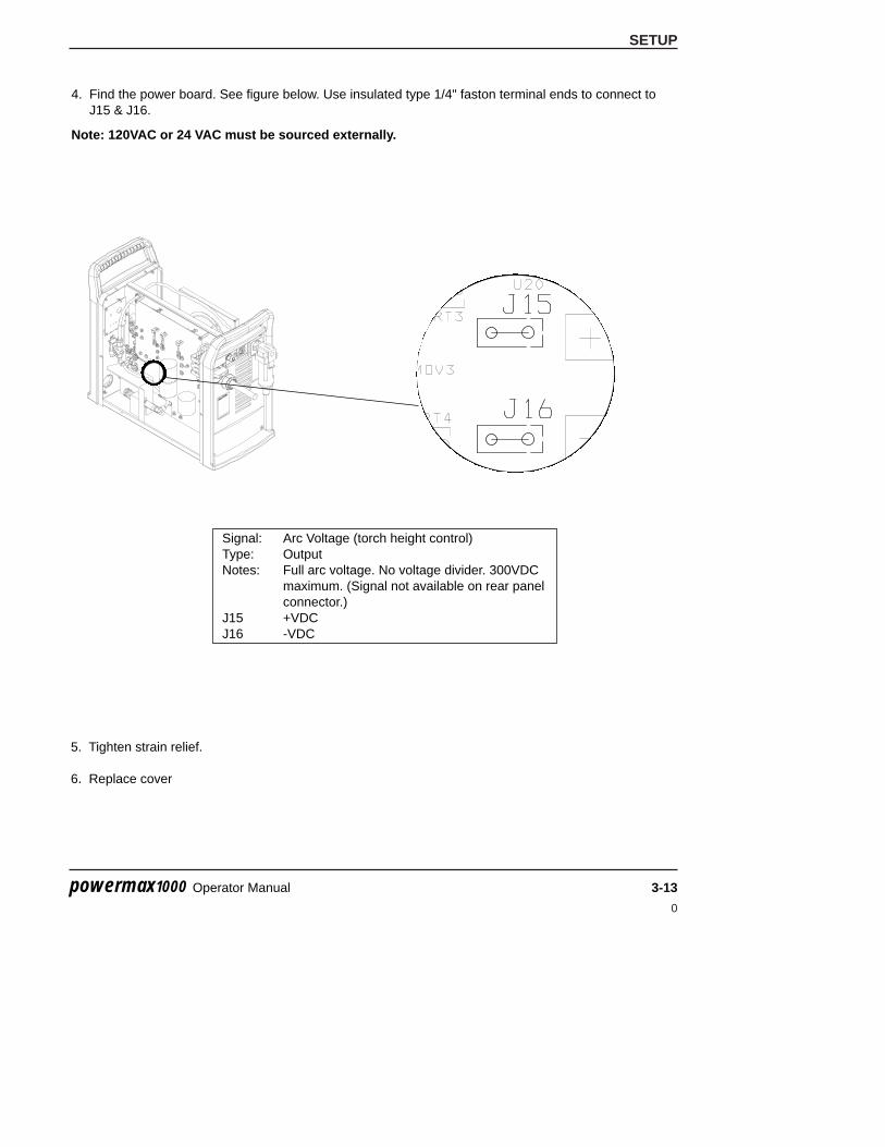
SETUP
0
powermax1000 Operator Manual 3-13
4. Find the power board. See figure below. Use insulated type 1/4" faston terminal ends to connect toJ15 & J16.
Note: 120VAC or 24 VAC must be sourced externally.
Signal: Arc Voltage (torch height control)Type: OutputNotes: Full arc voltage. No voltage divider. 300VDC
maximum. (Signal not available on rear panelconnector.)
J15 +VDCJ16 -VDC
5. Tighten strain relief.
6. Replace cover

SETUP
0
3-14 powermax1000 Operator Manual
Changing XFER (start machine motion) from dry contact closure to voltage signal
24 VDC (chassis ground reference) at 100ma max is available at J19 on Power PCB to drive aIsolated/Floating device such as a 24 VDC relay coil (240 ohms or greater) or a Typical Industrial InputIsolation Module (which has an opto-coupler built-in). Shown below are typical connections for a high sidedrive arrangement.
Driving a Relay Coil
Notes:
1) 24 VDC RelayRecoil >240 ohms
2) Must use suppressiondiode (1A, 100V)such as IN4002through IN4004 typeacross coil.
Move Black wire and addJumper as shown
GN
D24
VD
CB
LKY
EL
RE
DW
HT
J19 XFER
STARTSIGNAL
BLK
SHIELD
START
431412
13

SETUP
0
powermax1000 Operator Manual 3-15
Driving an Industrial Isolated Input Module
Move Black wire and addJumper as shown
GN
D24
VD
CB
LKY
EL
RE
DW
HT
J19
STARTSIGNAL
BLK
SHIELD+
–
ISOLATEDINPUT
MODULE
XFER START
431412
13

0
powermax1000 Operator Manual 4-1
Section 4
OPERATION
In this section:
Controls and Indicators .............................................................................................................................4-2Indicator LEDs .................................................................................................................................4-2
Torch Consumable Configurations ............................................................................................................4-3Installing Torch Consumables ...................................................................................................................4-4Mode Switch..............................................................................................................................................4-5Turn Power ON .........................................................................................................................................4-5Check Indicator Lights...............................................................................................................................4-5Adjust Gas Pressure and Current Setting .................................................................................................4-6Hand Torch Operation ...............................................................................................................................4-7
Safety Trigger Operation .................................................................................................................4-7Attach the Work Clamp....................................................................................................................4-8Starting a Cut from the Edge of the Workpiece ...............................................................................4-8Hand Torch Cutting Technique.........................................................................................................4-9Piercing..........................................................................................................................................4-10Gouging .........................................................................................................................................4-11
Cut Charts ...............................................................................................................................................4-12

OPERATION
0
4-2 powermax1000 Operator Manual
Controls and Indicators
6.0BAR
5.04.0
PSI807050 60
50
30
AMPS
60
20
VAC
+_
40
Current(Amps)AdjustmentKnob
Mode Switch
IndicatorLEDs
PressureGauge
PressureRegulator
ON (I) / OFF (0)Switch
Green Power ON LEDWhen illuminated, indicates that power is applied to system and power switch is ON ( I ).
Gas Pressure LEDYellow: When flashing, indicates that the gas pressure is below 60 psig (4.1 bar) for cutting,or 40 psig (2.8 bar) for gouging.Green: When illuminated, indicates acceptable gas pressure for torch operation.
Yellow Torch Cap LEDWhen illuminated, indicates that the Retaining Cap is loose or not installed.NOTE: Condition must be corrected and power turned OFF then ON to clear LED.
Yellow Temp LEDWhen illuminated, indicates that the power supply temperature has exceeded its operatinglimit.
Red Fault LEDWhen illuminated, indicates that a fault condition exists, which prevents system operation.
Yellow Low Line Voltage LEDWhen illuminated, indicates that line voltage is below 170 VAC or above 680 VAC. On CEunits, it can also indicate a missing phase.
AC
V
Indicator LEDs
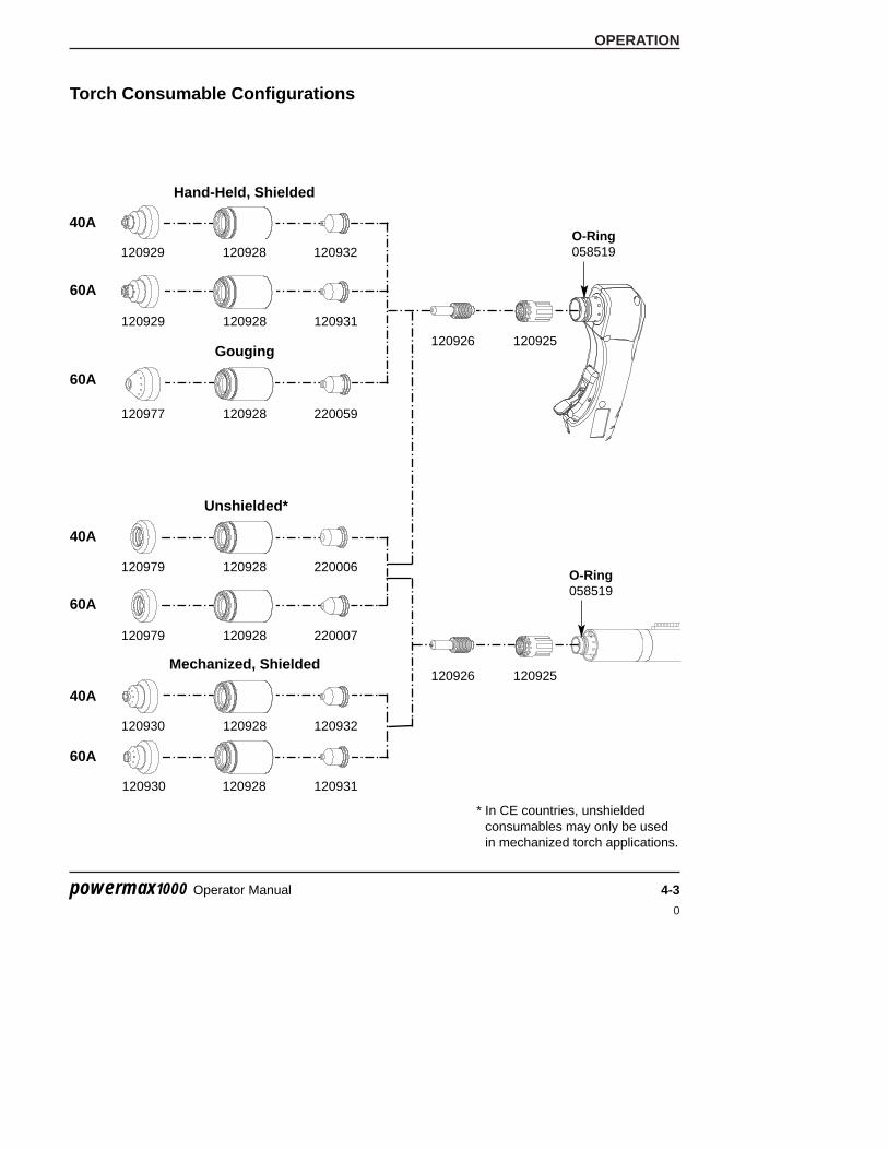
OPERATION
0
powermax1000 Operator Manual 4-3
Torch Consumable Configurations
Hand-Held, Shielded
120929
120925120926
120932120928
120929 120931120928
Mechanized, Shielded
120930 120932120928
120930 120931120928
120979 220007120928
Unshielded*
120979 220006120928
Gouging
120977 220059120928
40A
60A
40A
60A
40A
60A
60A
* In CE countries, unshieldedconsumables may only be usedin mechanized torch applications.
120925120926
O-Ring058519
O-Ring058519

OPERATION
0
4-4 powermax1000 Operator Manual
WARNINGINSTANT-ON TORCHES
PLASMA ARC CAN CAUSE INJURY AND BURNS
Plasma arc comes on immediately when the torch switch is activated. The plasma arc will quickly burn through gloves and skin. Make sure power is OFF before changing consumables.
Installing Torch Consumables
�
� Hand tighten only.
Retaining Cap
Nozzle
Electrode
Swirl Ring
Shield

OPERATION
0
powermax1000 Operator Manual 4-5
�
Mode Switch
Use to cut expanded metal.Automatically reinitiates pilot.
Use to cut plate/sheet metal.Optimum consumable life.
Use to gouge, or for non-transfered-arc operation.
Turn ON Power
Position the power switch to ON (1) as shown.
Check that the POWER ON lamp is illuminated.
Check Indicator Lights
AC
V
Check that the remaining indicator lamps are NOT illuminated.
See Maintenance Section for details.
�
Check that the Gas Pressure LED is illuminated in Green.

OPERATION
0
4-6 powermax1000 Operator Manual
Adjust Gas Pressure and Current Setting
20
60
AMPS
30 40
50
Set current knob to gas test.
Pull regulator knob to unlock.
�
�
6.0BAR
5.04.0
PSI807050 60
20
60
AMPS
30 40
50
Set pressure:Cutting 70–75 psig (4.8–5.2 bar)Gouging 50–60 psig (3.4–4.1 bar)
Push regulator knob to lock.
Turn current knob away from gas test to stopgas flow (20 amps minimum).
�
�
�
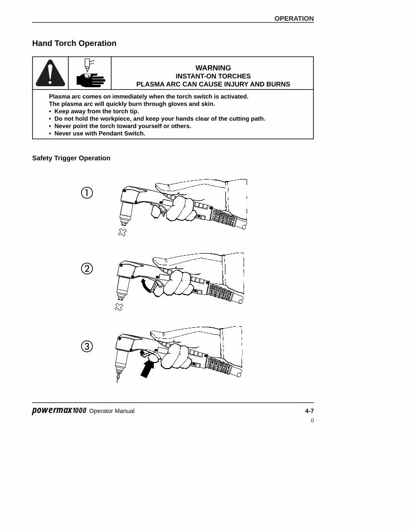
OPERATION
0
powermax1000 Operator Manual 4-7
Hand Torch Operation
Safety Trigger Operation
�
�
�
WARNINGINSTANT-ON TORCHES
PLASMA ARC CAN CAUSE INJURY AND BURNS
Plasma arc comes on immediately when the torch switch is activated. The plasma arc will quickly burn through gloves and skin.• Keep away from the torch tip.• Do not hold the workpiece, and keep your hands clear of the cutting path.• Never point the torch toward yourself or others.• Never use with Pendant Switch.

OPERATION
0
4-8 powermax1000 Operator Manual
Attach the work clamp securely to theworkpiece. Remove rust, paint or othercoatings to ensure good electrical contact.
Attach the work clamp as close as possibleto the area being cut, to reduce exposureto electromagnetic fields (EMF).
Do not attach the work clamp to the portionthat will fall away.
Starting a Cut from theEdge of the Workpiece
Hold the torch nozzle vertical at the edge ofthe workpiece.
Start cutting from the edge of theworkpiece.
Pause at the edge until the arc hascompletely cut through the workpiece.
Then, proceed with the cut.
Attach the Work Clamp
WARNINGSPARKS AND HOT METAL CAN INJURE
EYES AND BURN SKIN
When firing the torch at an angle, sparks and hot metal will spray out fromthe nozzle. Point the torch away from yourself and others.

OPERATION
0
powermax1000 Operator Manual 4-9
Hand Torch Cutting Technique
Firing the torch unnecessarily reduces nozzle and electrode life.
When cutting, make sure that sparks are exiting from thebottom of the workpiece.
If sparks are spraying up from the workpiece, you aremoving the torch too fast, or without sufficient power.
Position the torch nozzle at a vertical position and watch thearc as it cuts along the line.
Shielded Consumables. Do not push down on the torchwhen cutting. Lightly drag the torch across the workpieceto maintain a steady cut.
• Pulling the torch through the cut is easier than pushing it.• To cut thin material, reduce the amps until you get the best quality cut.• For straight-line cuts, use a straight edge as a guide. To cut circles, use
a template or a Hypertherm circle cut guide, Part No. 027668.
Unshielded Consumables. Maintain an approximate 1/8 inch (3 mm) torch-to-work distance.

OPERATION
0
4-10 powermax1000 Operator Manual
WARNINGSPARKS AND HOT METAL CAN INJURE
EYES AND BURN SKIN
When firing the torch at an angle, sparks and hot metal will spray outfrom the nozzle. Point the torch away from yourself and others.
Piercing
Hold the torch so that the nozzle is within 1/8 inch (3 mm) from the workpiece before firing the torch.
Fire the torch at an angle to theworkpiece, then slowly rotate it toan upright position.
When sparks are exiting from thebottom of the workpiece, the archas pierced through the material.
When the pierce is complete,proceed with the cut.

OPERATION
0
powermax1000 Operator Manual 4-11
WARNINGSPARKS AND HOT METAL CAN INJURE
EYES AND BURN SKIN
When firing the torch at an angle, sparks and hot metal will spray outfrom the nozzle. Point the torch away from yourself and others.
Gouging
Hold the torch so that the nozzle is within 1/16 inch (1.5 mm) from the workpiece before firing the torch.
Hold the torch at a 45 degree angleto the work piece. Pull the trigger toobtain a pilot arc. Transfer the arcto the work piece.
Maintain a 45° angle, approximately,from the workpiece.
Feed into the gouge.
NOTE: A heat shield is available foradded hand and torch protection,Part No. 220049.Direction of travel
45°

OPERATION
0
4-12 powermax1000 Operator Manual
Cut Charts60 Amp Mechanized Shielded Consumables• Torch-to-work distance for the following cut chart is 1/16 inch (1.5 mm) for all cuts.
Retaining Cap120928
Nozzle120931
Electrode120926
Swirl Ring120925
T60MTorch
Shield120930
Mild Steel
Inches mm IPM mm/min IPM mm/min134 16 Ga 1.5 627 15926 502 12751134 10 Ga 3.4 264 6706 211 5359138 0.25 1/4" 6.4 132 3353 86 2184141 0.75 3/8" 9.5 63 1600 41 1041141 1/2" 12.7 42 1067 27 686147 5/8" 15.9 31 787 20 512153 3/4" 19.0 22 559 14 363
Stainless
Inches mm IPM mm/min IPM mm/min134 0 16 Ga 1.5 625 15875 406 10312136 0.25 10 Ga 3.4 244 6198 159 4039139 0.50 1/4" 6.4 110 2794 72 1829145 0.75 3/8" 9.5 53 1346 34 864146 1/2" 12.7 35 889 23 584149 5/8" 15.9 26 660 17 429154 3/4" 19.0 18 457 12 297
Aluminum
Inches mm IPM mm/min IPM mm/min135 0 1/16" 1.6 666 16916 433 10995138 1/8" 3.2 400 10160 260 6604141 1/4" 6.4 145 3683 94 2388146 0.75 3/8" 9.5 74 1880 48 1219149 1/2" 12.7 51 1295 30 762153 5/8" 15.9 33 838 21 545
Optimum Travel SpeedsArc Voltage
Material ThicknessArc Current
Maximum Travel Speeds
Arc Voltage
Pierce Delay
Material Thickness Maximum Travel Speeds
Pierce Delay
Arc Current
Arc Voltage
Pierce Delay
Material Thickness Maximum Travel Speeds
Arc Current
Optimum Travel Speeds
60
60
60
0
1.50
2.00
0.25
1.50
Maximum travel speeds are the fastest travel speeds possible to cut the material without regard to cut quality.Optimum travel speeds provide the best cut angle, least dross and best cut surface finish. Remember that cut chartsare intended to provide a good starting point for each different cut assignment. Every cutting system requires“fine tuning” for each cutting application in order to obtain the desired cut quality.

OPERATION
0
powermax1000 Operator Manual 4-13
40 Amp Mechanized Shielded Consumables• Torch-to-work distance for the following cut chart is 1/16 inch (1.5 mm) for all cuts.
Retaining Cap120928
Nozzle120932
Electrode120926
Swirl Ring120925
T60MTorch
Shield120930
Mild Steel
Inches mm IPM mm/min IPM mm/min147 26 GA 0.5 638 16205 415 10541148 22 GA 0.8 500 12700 325 8255149 18 GA 1.3 312 7925 203 5156152 16 GA 1.5 176 4470 114 2896144 0.25 14 GA 1.9 640 16256 221 5613146 0.50 10 GA 3.4 151 3835 98 2489147 0.75 3/16 4.7 97 2464 63 1600149 1.00 1/4 6.4 74 1880 48 1219
Stainless
Inches mm IPM mm/min IPM mm/min139 26 GA 0.5 631 16027 410 10414139 22 GA 0.8 496 12598 322 8179142 18 GA 1.3 592 15037 335 8509144 16 GA 1.5 374 9500 243 6172144 14 GA 1.9 221 5613 144 3658147 0.50 10 GA 3.4 107 2718 70 1778149 0.75 3/16 4.7 67 1702 44 1118149 1.00 1/4 6.4 47 1194 31 787
Aluminum
Inches mm IPM mm/min IPM mm/min150 1/32 0.8 610 15494 397 10084152 1/16 1.5 268 6807 174 4420146 0.25 3/32 2.4 293 7442 190 4826149 0.50 1/8 3.2 204 5182 133 3378151 1.00 1/4 6.4 76 1930 49 1245
25
40
0
Optimum Travel Speeds
Optimum Travel Speeds
Arc Current
Maximum Travel Speeds
Arc Current
Arc Voltage
Pierce Delay
Material Thickness
40
25
Optimum Travel SpeedsArc Voltage
Pierce Delay
Maximum Travel Speeds
0
Material Thickness
Maximum Travel Speeds
25
40
Arc Current
0.25
0
Arc Voltage
Pierce Delay
Material Thickness
Maximum travel speeds are the fastest travel speeds possible to cut the material without regard to cut quality.Optimum travel speeds provide the best cut angle, least dross and best cut surface finish. Remember that cut chartsare intended to provide a good starting point for each different cut assignment. Every cutting system requires“fine tuning” for each cutting application in order to obtain the desired cut quality.

OPERATION
0
4-14 powermax1000 Operator Manual
40 Amp Unshielded Consumables• Torch-to-work distance for the following cut chart is 1/16 inch (1.5 mm) for all cuts.
Retaining Cap120928
Nozzle220006
Electrode120926
Swirl Ring120925
T60MTorch
Deflector120979
Mild Steel
Inches mm IPM mm/min IPM mm/min125 26 GA 0.5 550 13970 353 8966128 22 GA 0.8 484 12294 315 8001130 18 GA 1.3 238 6045 155 3937131 16 GA 1.5 167 4242 109 2769
40 129 0.25 14 GA 1.9 326 8280 212 5385
Stainless
Inches mm IPM mm/min IPM mm/min127 26 GA 0.5 561 14249 365 9271127 22 GA 0.8 453 11506 295 7493123 18 GA 1.3 500 12700 325 8255127 16 GA 1.5 367 9322 239 6071128 14 GA 1.9 220 5588 143 3632
Aluminum
Inches mm IPM mm/min IPM mm/min125 1/32 0.8 564 14326 366 9296127 1/16 1.5 236 5994 153 3886
40 127 0.25 3/32 2.4 261 6629 170 4318
Arc Current
Material Thickness
25
25
Arc Voltage
Pierce Delay
0
Arc Current
Optimum Travel SpeedsMaterial Thickness Maximum Travel Speeds
Optimum Travel SpeedsMaximum Travel SpeedsMaterial Thickness
Optimum Travel Speeds
25
40
0
0.25
Arc Current
Arc Voltage
Pierce Delay
0
Arc Voltage
Pierce Delay
Maximum Travel Speeds
Maximum travel speeds are the fastest travel speeds possible to cut the material without regard to cut quality.Optimum travel speeds provide the best cut angle, least dross and best cut surface finish. Remember that cut chartsare intended to provide a good starting point for each different cut assignment. Every cutting system requires“fine tuning” for each cutting application in order to obtain the desired cut quality.

0
powermax1000 Operator Manual 5-1
Section 5
MAINTENANCE AND PARTS
In this section:
Routine Maintenance ................................................................................................................................5-2Inspect Consumables................................................................................................................................5-3Controls and Indicators .............................................................................................................................5-4Basic Troubleshooting...............................................................................................................................5-5System Circuit Diagram ............................................................................................................................5-8 Technical Questions ..................................................................................................................................5-9Parts........................................................................................................................................................5-10
Torch Consumable Configurations ................................................................................................5-10Torch Parts.....................................................................................................................................5-11Power Supply Parts .......................................................................................................................5-11Accessories ...................................................................................................................................5-12

MAINTENANCE AND PARTS
0
5-2 powermax1000 Operator Manual
Routine Maintenance
Each Use
6.0BAR
5.04.0
PSI807050 60
Check gas pressure.
Replace damaged powercord or plug.
Replace damaged torch lead.
Check pressure hose, filterelement, and connectionsfor leaks.
Clean the inside ofthe power supplywith air pressure orvacuum.
Replace damaged labels.
Check torch cap-on safety switch:observe that red fault LED and yellowtorch cap LED illunimate when cap isloosened.
Check consumables for wearand proper installation.
Check trigger for damage. Check torchbody for cracks or exposed wires.
Each Week
6 Months
3 Months
WARNINGELECTRIC SHOCK CAN KILL
Disconnect electrical power before performing any maintenance.All work requiring removal of the power supply cover must be performed by a qualified technician.

MAINTENANCE AND PARTS
0
powermax1000 Operator Manual 5-3
Inspect Consumables
Nozzle
Center hole Good Worn Replace
Roundness of through hole
Center surface Maximum pit depth Replace1/32 inch (0.8 mm)
Electrode
Part Check For Action
External surfaces Damage or debris Replace
Central bore (I.D.) Does electrode slide easily? Replace
Gas holes Blocked holes Replace
Swirl Ring
External surfaces Damage or wear Replace
Dry surface Apply a thin film ofHypertherm grease(Part No. 027055)
Torch O-ring
Max. 1/32 inch(0.8 mm)

MAINTENANCE AND PARTS
0
5-4 powermax1000 Operator Manual
Controls and Indicators
6.0BAR
5.04.0
PSI807050 60
50
30
AMPS
60
20
VAC
+_
40
Current(Amps)AdjustmentKnob
Mode Switch
IndicatorLEDs
PressureGauge
PressureRegulator
ON (I) / OFF (0)Switch
Green Power ON LEDWhen illuminated, indicates that power is applied to system and power switch is ON ( I ).
Gas Pressure LEDYellow: When flashing, indicates that the gas pressure is below 60 psig (4.1 bar) for cutting,or 40 psig (2.8 bar) for gouging.Green: When illuminated, indicates acceptable gas pressure for torch operation.
Yellow Torch Cap LEDWhen illuminated, indicates that the Retaining Cap is loose or not installed.NOTE: Condition must be corrected and power turned OFF then ON to clear LED.
Yellow Temp LEDWhen illuminated, indicates that the power supply temperature has exceeded its operatinglimit.
Red Fault LEDWhen illuminated, indicates that a fault condition exists, which prevents system operation.
Yellow Low Line Voltage LEDWhen illuminated, indicates that line voltage is below 170 VAC or above 680 VAC. On CEunits, it can also indicate a missing phase.
AC
V
Indicator LEDs

MAINTENANCE AND PARTS
0
powermax1000 Operator Manual 5-5
Basic Troubleshooting
V
AC
Problem Cause / Solution
1. The ON/OFF power switch is set to I (ON), and the POWER ON (GREEN)lamp is not illuminated.
1.1 The power cord is not plugged into the powerreceptacle.Plug the power cord into the receptacle.
1.2 The disconnect power switch is not set to ONor there is no power available to the disconnectpower switch box.Turn on the power at the main power panel or atthe disconnect power switch box.
2. The POWER ON (GREEN), LOW GASPRESSURE RANGE (YELLOW) isflashing and FAULT (RED) lamps areilluminated.
2.1 The gas supply is turned OFF or not connectedto the power supply.Check that the gas is turned on and is connectedto the power supply.
2.2 The incoming gas pressure is too low.Set incoming gas pressure to 90-120 psig / 6.2-8.3bar. Check that there are no leaks in the gassupply line.
2.3 Output gas pressure is set too low for selectedmode.Adjust gas pressure. See page 4-6 (item 3) forpressure settings.
3. The POWER ON, LINE VOLTAGERANGE (YELLOW) and FAULT (RED)lamps are illuminated.
3.1 Line voltage is too low, too high, or a phase(CE system only) is missing. Have a qualified technician check incoming power.
4. The POWER ON (GREEN),TEMPERATURE (YELLOW) andFAULT (RED) lamps are illuminated.
4.1 One of the internal thermostat switches hasopened due to overheating or extremely lowtemperature.Leave the power supply on to allow the fan to coolthe power supply (overheating). Move the powersupply to a warm location (extreme cold).
Note: Fan on/off is automatic. Fan may notbe in operation when power is ON.

MAINTENANCE AND PARTS
0
5-6 powermax1000 Operator Manual
Basic Troubleshooting (continued)
Problem Cause / Solution
5. The POWER ON (GREEN), TORCHPARTS LOOSE OR REMOVED(YELLOW) and FAULT (RED) lamps areilluminated.
5.1 Retaining Cap is loose or removed from thetorch.Turn off power supply and tighten or install torchconsumables. See Installing Torch Consumables,Section 4.
If the torch consumables become loose or wereremoved while the power supply is on, turn off thepower supply, correct the problem and then turn onthe power supply to clear this fault.
6. The arc does not transfer to theworkpiece.
6.1 The work clamp is not connected to theworkpiece, or the work clamp is broken.Connect or repair the work clamp.
6.2 The work clamp is not making good metal-to-metal contact.Clean the area where the clamp contacts theworkpiece.
6.3 The torch is too far away from the workpiece.Move the torch head closer to the workpiece andstart the torch again.See Torch Operation, Section 4.
7. The arc blows out, but re-ignites whenthe torch switch is depressed again.
7.1 The consumable parts are worn or damaged.Inspect and change the consumables, as necessary. See Inspect Consumables, in thissection.See Torch Operation, Section 4.
7.2 The gas pressure is incorrect.Adjust the operating gas pressure. See Check andAdjust Gas Pressure, Section 4. Check that thegas pressure to the power supply is not less than 90 psig (6.1 bar) at a flow of 6 scfm (169 l/m).
7.3 The gas filter element outside the power supplyis contaminated.Replace filter element. See Air Filter Element Replacement, in this section.

MAINTENANCE AND PARTS
0
powermax1000 Operator Manual 5-7
Basic Troubleshooting (continued)
Problem Cause / Solution
8. The arc sputters and hisses. 8.1 The gas filter element outside the power supplyis contaminated.Replace filter element.
8.2 There is water in the air line.Clean air filter or add additional air filtration topower supply. See Additional Gas Filtration,Section 3.
8.3 Worn or incorrectly installed consumables.Inspect consumables. Replace if necessary.
9. Cut quality is not good. 9.1 Consumables are worn or the torch is beingused incorrectly.See Inspect Consumables, in this section.See Hand Torch Operation, Section 4.
10. The POWER ON (GREEN) and FAULT(RED) lamps are flashing.
10.1 Self diagnostic failure.System needs repair.
11. The POWER ON (GREEN) and FAULT(RED) lamps are illuminated afterpower is turned on.
11.1 Start signal ON when system power isinitiated.Turn start signal OFF. Turn power OFF and thenON again.
12. The POWER ON (GREEN) andFAULT (RED) lamps are illuminatedfor 10 seconds after trigger switchis activated.
12.1 Consumables stuck or jammed.Turn power OFF and Check consumables.
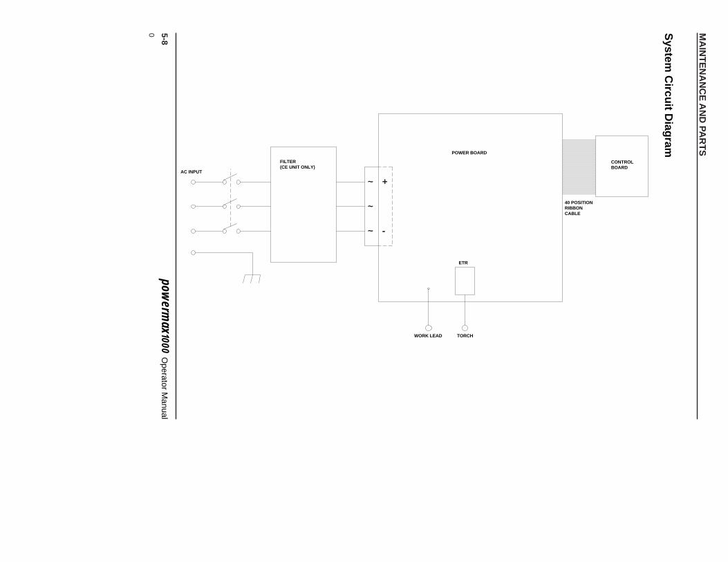
MA
INT
EN
AN
CE
AN
D PA
RT
S
0 5-8pow
erm
ax
100
0O
perator Manual
++
--~~
~~
~~
AC INPUT
FILTER(CE UNIT ONLY)
POWER BOARD
ETR
WORK LEAD TORCH
40 POSITIONRIBBONCABLE
CONTROLBOARD
System
Circu
it Diag
ram

MAINTENANCE AND PARTS
0
powermax1000 Operator Manual 5-9
Technical QuestionsIf you are unable to fix the problem by following this basic troubleshooting guide or if you need furtherassistance:
1. Call your Hypertherm distributor or authorized Hypertherm repair facility.
2. Call the nearest Hypertherm office listed in the front of this manual.
3. Request a Powermax1000 Service Manual for wiring diagrams, higher-level troubleshooting andmore parts list information.

MAINTENANCE AND PARTS
0
5-10 powermax1000 Operator Manual
Parts
Torch Consumable Configurations
Hand-Held, Shielded
120929
120925
O-Ring058519
120926
120932120928
120929 120931120928
Mechanized, Shielded
120930 120932120928
120930 120931120928
120979 220007120928
Unshielded*
120979 220006120928
Gouging
120977 220059120928
40A
60A
40A
60A
40A
60A
60A
* In CE countries, unshieldedconsumables may only be usedin mechanized torch applications.
120925120926
O-Ring058519

MAINTENANCE AND PARTS
0
powermax1000 Operator Manual 5-11
Torch parts
083172 T60 Hand Torch Assembly, 25'083171 T60 Hand Torch Assembly, 50'083175 T60M Machine Torch Assembly, 15'083174 T60M Machine Torch Assembly, 25'083176 T60M Machine Torch Assembly, 35'083177 T60M Machine Torch Assembly, 50'027055 Silicon Lubricant, 1/4 Oz. Tube015337 NIP: 1/4 NPT Qdisc STL (Non-CE)015145 Adapter: 1/4 NPT x G1/4 BSPP RH BRS (CE)058519 Torch O-Ring128644 T60 Hand Torch Handle Replacement Kit (5 Screws included)075586 T60 Hand Torch Handle Screw (5 Required)220061 Shield Cap: T60M/T80M Ohmic Contact
Power Supply Parts
083178 Powermax 1000 Hand System, 200-600V, 1/3PH, 50/60Hz, CSA, Auto-Voltage/Phase (Not CE Compliant), 25 Ft. Torch & Lead Assembly
083179 Powermax 1000 Hand System, 200-600V, 1/3PH, 50/60Hz, CSA, Auto-Voltage/Phase (Not CE Compliant), 50 Ft. Torch & Lead Assembly
083182 Powermax 1000 Machine System, 200-600V, 1/3PH, 50/60Hz, CSA, Auto-Voltage/Phase (Not CE Compliant), 25 Ft. Torch & Lead Assembly
083183 Powermax 1000 Machine System, 200-600V, 1/3PH, 50/60Hz, CSA, Auto-Voltage/Phase (Not CE Compliant), 50 Ft. Torch & Lead Assembly
083192 Powermax 1000 Hand System, 230-400V, 3PH, 50/60Hz, CE, Auto-Voltage,25 Ft. Torch & Lead Assembly
083193 Powermax 1000 Hand System, 230-400V, 3PH, 50/60Hz, CE, Auto-Voltage,50 Ft. Torch & Lead Assembly
083194 Powermax 1000 Machine System, 230-400V, 3PH, 50/60Hz, CE, Auto-Voltage, 25 Ft. Torch & Lead Assembly
083195 Powermax 1000 Machine System, 230-400V, 3PH, 50/60Hz, CE, Auto-Voltage, 50 Ft. Torch & Lead Assembly
110394 Cover Assembly, Non-CE (12 Screws Included)110395 Cover Assembly, CE (12 Screws included)075533 Cover Screws (Individual Cover Screw)128327 Filter Bowl w/ Fittings129654 ETR Door Assembly129405 Consumable Box123645 Ground Clamp w/ Cable & Strain relief129652 Power Cable, Standard 3PH129726 Power Cable, CE, 3PH

MAINTENANCE AND PARTS
0
5-12 powermax1000 Operator Manual
Accessories
128646 Wheel Kit128647 Optional Air Filtration Kit
011093 Replacement Filter For Optional Air Filtration Kit011092 Replacement Filter Element For Filter Kit027668 Circle Cutting Guide Assembly027684 Replacement Bushing for Circle Cutting Guide Assembly123646 50 Ft (15M) Work Cable w/ clamp128711 CE Stain Relief Inserts - Standard Cord128712 CE Strain Relief Inserts - Non-standard Cord023206 CNC Interface Cable220049 Hand Heat Shield, Gouging128650 On/Off Pendant for Machine Torch, 25 Ft (7.5M)128651 On/Off Pendant for Machine Torch, 50 Ft (15M)128652 On/Off Pendant for Machine Torch, 75 Ft (22.5M)