p&r metals call toll-free: 1-877-880-3319 stair tread ... · gauge .080” .100” .080”...
TRANSCRIPT

14
P&R METALS CALL TOLL-FREE: 1-877-880-3319
GRIP STRUT® STAIR TREADS
6
Stair Tread InformationSafe Loading — Stair Treads
Load data below takes eccentric loads into consideration. Although load values include allowances for normal impact conditions andusual pedestrian traffic, be sure to make provisions in the structural design for special uses and loads involving unusual impactforces or vibratory forces. Load-carrying capacity of stair treads increases as side channel height and gauge or material increase.
U=Uniform Load (lb./ft.2) C= Concentrated Load (lb.)
2-Diamond 3-Diamond 4-Diamond 5-Diamond43/4” Depth 7” Depth 91/2” Depth 113/4” Depth
Material Steel Steel Steel SteelGauge 14 12 14 12 14 12 14 12
ChannelSpan Depth - in. (mm) U C U C U C U C U C U C U C U C
2’-0”11/2” (38.1) 1191 472 1576 624 761 443 1006 587 549 435 750 595 434 425 575 563
2” (50.8) 1978 783 2513 995 1262 737 1604 936 911 604 1158 917 721 573 916 897
2’-6”11/2” (38.1) 764 378 1011 500 488 356 645 470 353 349 481 476 278 342 369 452
2” (50.8) 1268 611 1611 797 810 590 1029 750 584 578 742 734 463 566 587 719
3’-0”11/2” (38.1) 532 315 703 418 340 300 450 393 245 300 335 398 194 300 258 378
2” (50.8) 882 524 1121 665 563 492 716 626 407 483 517 614 322 473 409 601
4’-0” (1) 2” (50.8) 498 394 633 501 318 372 404 472 230 364 292 463 182 356 232 454
(1) Intermediate stringer is recommended for spans over 4”-0”.
2-Diamond 3-Diamond 4-Diamond 4-Diamond 5-Diamond 5-Diamond43/4” Depth 7” Depth 91/2” Depth 91/2” Depth 113/4” Depth 113/4” Depth
Material Aluminum Aluminum Aluminum Stainless Steel Aluminum Stainless SteelGauge .080” .100” .080” .100” .080” .100” 304 316L .080” .100” 304 316L
ChannelSpan Depth
in. (mm) U C U C U C U C U C U C U C U C U C U C U C U C
2’-0” 2” (50.8) 1328 526 1862 737 862 503 1208 705 607 481 867 687 610 483 525 416 396 388 607 595 394 386 338 3312’-6” 2” (50.8) 850 420 1191 590 551 402 773 564 388 392 555 550 390 387 336 336 253 388 388 540 252 381 216 3393’-0” 2” (50.8) 590 350 827 491 383 335 537 470 270 327 385 458 271 323 233 279 176 321 270 450 175 319 150 275
4’-0” (1) 2” (50.8) 332 263 465 369 215 252 302 353 152 245 216 344 152 244 131 210 99 241 151 338 98 241 84 221
(1) Intermediate stringer is recommended for spans over 4”-0”.
15
P&R METALS CALL TOLL-FREE: 1-877-880-3319
GRIP STRUT® STAIR TREADS
7
Stair Tread Information
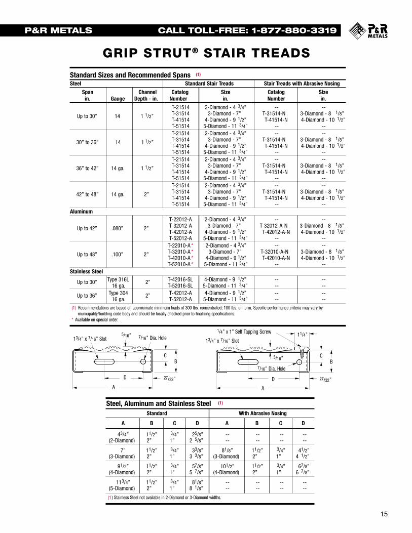
Steel, Aluminum and Stainless Steel (1)
Standard With Abrasive Nosing
A B C D A B C D
43/4” 11/2” 3/4” 25/8” -- -- -- --(2-Diamond) 2” 1” 2 5/8” -- -- -- --
7” 11/2” 3/4” 33/8” 81/8” 11/2” 3/4” 41/2”(3-Diamond) 2” 1” 3 3/8” (3-Diamond) 2” 1” 4 1/2”
91/2” 11/2” 3/4” 57/8” 101/2” 11/2” 3/4” 67/8”(4-Diamond) 2” 1” 5 7/8” (4-Diamond) 2” 1” 6 7/8”
113/4” 11/2” 3/4” 81/8” -- -- -- --(5-Diamond) 2” 1” 8 1/8” -- -- -- --
(1 ) Stainless Steel not available in 2-Diamond or 3-Diamond widths.
Standard Sizes and Recommended Spans (1)
Steel Standard Stair Treads Stair Treads with Abrasive Nosing
Span Channel Catalog Size Catalog Sizein. Gauge Depth - in. Number in. Number in.
T-21514 2-Diamond - 4 3/4” -- --
Up to 30” 14 1 1/2” T-31514 3-Diamond - 7” T-31514-N 3-Diamond - 8 1/8”T-41514 4-Diamond - 9 1/2” T-41514-N 4-Diamond - 10 1/2”T-51514 5-Diamond - 11 3/4” -- --T-21514 2-Diamond - 4 3/4” -- --
30” to 36” 14 1 1/2” T-31514 3-Diamond - 7” T-31514-N 3-Diamond - 8 1/8”T-41514 4-Diamond - 9 1/2” T-41514-N 4-Diamond - 10 1/2”T-51514 5-Diamond - 11 3/4” -- --T-21514 2-Diamond - 4 3/4” -- --
36” to 42” 14 ga. 1 1/2” T-31514 3-Diamond - 7” T-31514-N 3-Diamond - 8 1/8”T-41514 4-Diamond - 9 1/2” T-41514-N 4-Diamond - 10 1/2”T-51514 5-Diamond - 11 3/4” -- --T-21514 2-Diamond - 4 3/4” -- --
42” to 48” 14 ga. 2” T-31514 3-Diamond - 7” T-31514-N 3-Diamond - 8 1/8”T-41514 4-Diamond - 9 1/2” T-41514-N 4-Diamond - 10 1/2”T-51514 5-Diamond - 11 3/4” -- --
AluminumT-22012-A 2-Diamond - 4 3/4” -- --
Up to 42” .080” 2” T-32012-A 3-Diamond - 7” T-32012-A-N 3-Diamond - 8 1/8”T-42012-A 4-Diamond - 9 1/2” T-42012-A-N 4-Diamond - 10 1/2”T-52012-A 5-Diamond - 11 3/4” -- --
T-22010-A * 2-Diamond - 4 3/4” -- --
Up to 48” .100” 2” T-32010-A * 3-Diamond - 7” T-32010-A-N 3-Diamond - 8 1/8”T-42010-A * 4-Diamond - 9 1/2” T-42010-A-N 4-Diamond - 10 1/2”T-52010-A * 5-Diamond - 11 3/4” -- --
Stainless Steel
Up to 30” Type 316L 2” T-42016-SL 4-Diamond - 9 1/2” -- --16 ga. T-52016-SL 5-Diamond - 11 3/4” -- --
Up to 36” Type 304 2” T-42012-A 4-Diamond - 9 1/2” -- --16 ga. T-52012-A 5-Diamond - 11 3/4” -- --
(1) Recommendations are based on approximate minimum loads of 300 lbs. concentrated; 100 lbs. uniform. Specific performance criteria may vary bymunicipality/building code body and should be locally checked prior to finalizing specifications.
* Available on special order.
7/16” Dia. Hole
7/16” Dia. Hole13/4” x 7/16” Slot 13/4” x 7/16” Slot
1/4” x 1” Self Tapping Screw5/16”
5/16”
27/32”27/32”
11/4”
A
BC
D
A
BC
D

16
P&R METALS CALL TOLL-FREE: 1-877-880-3319
GRIP STRUT® SAFETY PLANKS
14 19
Grip Strut® Safe Loading Tables Grip Strut® Safe Loading Tables4-Diamond Plank __ 91/2” Width cont.
Allowable Loads and Deflections: U=Uniform Load (lb./ft.2) C= Concentrated Load (lb.) D=Deflection (in.)Spans to the left of heavy red line produce a deflection of 1/4” or less under a uniform load of 100 lb./ft.2
Channel Weight SpanMaterial Depth lb./lin.Gauge in. ft. Catalog
(mm) (kg/m) Number 2’-0” 2’-6” 3’-0’ 3’-6” 4’-0’ 4’-6” 5’-0’ 5’-6” 6’-0’ 6’-6” 7’-0’ 7’-6” 8’-0’ 9’-0’ 10’-0’ 11’-0” 12’-0”
U 499 319 222 163 124 9811/2”* 1.28 41512-A D .10 .15 .22 .31 .40 .51(38.1) (1.90) C 395 316 263 226 197 175
D .08 .12 .18 .25 .32 .41Alum. U 732 468 325 239 183 145 117 97 81 69Alloy 2” 1.37 42012-A D .08 .13 .18 .25 .33 .42 .52 .63 .74 .875052 (50.8) (2.03) C 568 463 386 331 290 257 232 211 192 177.080” D .06 .10 .15 .20 .27 .34 .42 .51 .59 .69
U 1099 704 489 359 275 217 176 145 122 104 90 78 6921/2”* 1.46 42512-A D .07 .10 .15 .21 .28 .35 .43 .53 .63 .74 .85 .98 1.12(63.5) (2.17) C 568 568 568 497 435 387 348 316 290 268 249 232 218
D .05 .07 .12 .17 .22 .28 .35 .42 .50 .59 .68 .78 .89U 1350 864 600 441 338 267 216 179 150 128 110 96 84
3”* 1.55 43012-A D .06 .09 .14 .19 .25 .31 .39 .47 .56 .66 .77 .88 1.00(76.2) (2.30) C 568 568 568 568 535 475 428 389 356 329 305 285 267
D .02 .05 .09 .14 .20 .25 .31 .38 .45 .53 .61 .70 .80
U 568 364 253 186 142 11211/2”* 1.62 41510-A D .09 .15 .22 .30 .39 .50(38.1) (2.41) C 450 360 300 257 225 200
D .07 .12 .17 .24 .31 .40Alum. U 1025 656 455 335 256 202 164 136 114 97 84 73 64Alloy 2” 1.74 42010-A D .09 .14 .20 .28 .37 .46 .58 .70 .83 .98 1.13 1.30 1.485052 (50.8) (2.58) C 811 649 541 464 406 361 325 295 270 250 232 216 203.100” D .07 .11 .16 .22 .29 .37 .46 .56 .66 .78 .90 1.04 1.18
U 1410 902 627 460 352 278 226 186 157 133 115 100 8821/2”* 1.85 42510-A D .07 .11 .16 .22 .28 .36 .44 .54 .64 .76 .88 1.01 1.15(63.5) (2.75) C 886 886 744 638 558 496 446 406 372 343 319 298 279
D .05 .09 .12 .17 .23 .29 .36 .43 .51 .60 .70 .81 .92U 1820 1165 809 594 455 360 291 241 202 172 149 129 114
3”* 1.97 43010-A D .05 .08 .12 .17 .22 .28 .34 .42 .50 .59 .68 .78 .89(76.2) (2.93) C 886 886 886 823 720 640 576 524 480 443 412 384 360
D .02 .05 .09 .13 .17 .22 .27 .33 .40 .47 .54 .62 .71
Product Selection/Design Tables
* Available on special order.
Engineering Data For Both Channels
Material Channel Sx Ix E IGauge Depth-in. in.3 in.4 lb. x in.2
Steel 11/2” .174 .102 2.96 x 10⁶
14 ga. 2” .270 .193 5.60 x 10⁶
21/2 .307 .335 9.71 x 10⁶
11/2” .216 .125 3.62 x 10⁶
Steel 2” .342 .264 7.66 x 10⁶
12 ga. 21/2 .504 .488 14.09 x 10⁶
3 .625 .722 20.94 x 10⁶
11/2” .171 .137 1.40 x 10⁶
Aluminum 2” .251 .246 2.51 x 10⁶
.080” 21/2 .379 .441 4.50 x 10⁶
3 .464 .602 6.14 x 10⁶
11/2” .196 .156 1.59 x 10⁶
Aluminum 2” .352 .309 3.15 x 10⁶
.100” 21/2 .486 .544 5.55 x 10⁶
3 .627 .911 9.29 x 10⁶
Stainless 304 2” .165 .1425 4.13 x 10616 ga.
Stainless 316L 2” .165 .1425 4.13 x 10616 ga.
Strut LoadingMaterial Type DeflectionGauge Loading** Load in.
Steel U 1844 .1514 ga. Cs 730 .11
Steel U 3537 .1412 ga. Cs 1400 .11
Aluminum U 1435 .19.080” Cs 568 .15
Aluminum U 2238 .23.100” Cs 886 .15
Stainless 304 U 1450 .2916 ga. Cs 574 .19
Stainless 316L U 1243 .2016 ga. Cs 492 .16
** U = Allowable Uniform Load (lb./ft.2)Cs = Allowable Concentrated Load per ft. of length at
mid-width (lb./ft.)
2-Diamond Plank __ 43/4” Width
Allowable Loads and Deflections: U=Uniform Load (lb./ft.2) C= Concentrated Load (lb.) D=Deflection (in.)Spans to the left of heavy red line produce a deflection of 1/4” or less under a uniform load of 100 lb./ft.2
Channel Weight SpanMaterial Depth lb./lin.Gauge in. ft. Catalog
(mm) (kg/m) Number 2’-0” 2’-6” 3’-0’ 3’-6” 4’-0’ 4’-6” 5’-0’ 5’-6” 6’-0’ 6’-6” 7’-0’ 7’-6” 8’-0’ 9’-0’ 10’-0’ 11’-0” 12’-0”
U 1324 849 591 435 334 265 215 179 15111/2” 2.3 21514 D .06 .10 .14 .20 .26 .32 .40 .49 .58(38.1) (3.42) C 524 420 351 301 265 236 213 195 179
D .05 .08 .11 .16 .20 .26 .32 .39 .47
U 2198 1409 980 721 553 438 356 295 248 212 184 161 142 113 93Steel 2” 2.6 22014 D .06 .09 .13 .17 .23 .29. .35 .43 .51 .60 .70 .81 .92 1.18 1.47
14 ga. (50.8) (3.87) C 870 697 582 499 438 390 352 321 295 273 255 239 225 201 183D .04 .07 .10 .14 .18 .23 .28 .34 .41 .48 .56 .65 .74 .94 .1.18
U 2522 1616 1124 827 634 502 408 338 285 244 211 184 163 139 106 88 7521/2” 2.8 22514 D .04 .06 .08 .11 .14 .18 .23 .27 .33 .38 .45 .51 .59 .75 .94 1.14 1.38(63.5) (4.17) C 998 800 667 573 502 447 404 368 338 313 292 273 257 231 210 193 178
D .03 .04 .06 .09 .11 .15 .18 .22 .26 .31 .36 .41 .47 .60 .75 .92 1.10
U 1751 1123 782 576 443 351 286 237 200 172 149 131 11611/2” 3.2 21512 D .07 .11 .15 .21 .27 .35 .43 .52 .62 .74 .86 .99 1.14(38.1) (4.76) C 693 556 464 399 350 313 283 258 238 221 206 194 183
D .05 .08 .12 .17 .22 .28 .34 .42 .50 .59 .69 .79 .91
U 2792 1790 1245 917 703 557 453 375 317 271 235 205 181 145 119 99 85Steel 2” 3.6 22012 D .05 .08 .11 .16 .20 .26 .32 .39 .46 .55 .63 .73 .84 1.07 1.34 1.64 1.98
12 ga. (50.8) (5.36) C 1105 886 739 635 557 496 448 409 376 348 325 305 287 258 235 216 201D .04 .06 .09 .12 .16 .21 .26 .31 .37 .44 .51 .59 .67 .86 1.07 1.31 1.58
U 4179 2676 1860 1368 1049 830 673 557 469 400 346 302 266 211 172 143 12121/2” 4.0 22512 D .04 .06 .09 .13 .17 .21 .26 .32 .38 .44 .51 .59 .67 .86 1.07 1.30 1.55(63.5) (5.95) C 1654 1324 1104 948 830 739 666 606 557 515 479 448 421 376 341 312 288
D .03 .05 .07 .10 .13 .17 .21 .25 .30 .35 .41 .47 .54 .69 .85 1.04 1.24
Product Selection/Design Tables
5/16”5/8”
90° ±21/2°
Depth± 1/16”
7/8” ± 1/8”
9/16”11/16”
11/16”
7/16”
43/4” ± 1/16”
9/32” 9/32”
11/8”
17/8” 17/8”
18 15
Grip Strut® Safe Loading Tables Grip Strut® Safe Loading Tables4-Diamond Plank __ 91/2” Width (available in stainless steel)
Allowable Loads and Deflections: U=Uniform Load (lb./ft.2) C= Concentrated Load (lb.) D=Deflection (in.)Spans to the left of heavy red line produce a deflection of 1/4” or less under a uniform load of 100 lb./ft.2
Channel Weight SpanMaterial Depth lb./lin.Gauge in. ft. Catalog
(mm) (kg/m) Number 2’-0” 2’-6” 3’-0’ 3’-6” 4’-0’ 4’-6” 5’-0’ 5’-6” 6’-0’ 6’-6” 7’-0’ 7’-6” 8’-0’ 9’-0’ 10’-0’ 11’-0” 12’-0”
U 663 426 296 219 168 134 109 90 7711/2” 3.6 41514 D .06 .10 .14 .20 .26 .33 .41 .50 .59(38.1) (5.36) C 525 421 352 303 266 238 215 197 182
D .05 .08 .11 .16 .21 .26 .33 .40 .47
U 1100 705 491 362 278 220 179 148 125 107 93 81 72 58 47Steel 2” 3.8 42014 D .06 .09 .13 .17 .23 .29 .36 .43 .52 .61 .71 .82 .94 1.20 1.51
14 ga. (50.8) (5.65) C 730 698 583 501 440 392 354 323 298 276 258 242 228 205 187D .04 .07 .10 .14 .18 .23 .28 .35 .41 .49 .57 .66 .75 .96 1.20
U 1262 809 563 415 318 252 205 170 144 123 106 93 82 66 54 4521/2” 4.1 42514 D .04 .06 .08 .11 .14 .18 .23 .28 .33 .39 .45 .52 .60 .76 .95 1.17(63.5) (6.10) C 730 730 669 574 504 449 406 370 341 316 295 277 261 235 214 197
D .02 .04 .06 .09 .12 .15 .18 .22 .26 .31 .36 .42 .48 .61 .76 .94
U 906 581 405 298 229 182 148 123 104 89 77 67 6011/2” 5.0 41512 D .07 .11 .16 .21 .28 .36 .44 .54 .64 .76 .89 1.02 1.17(38.1) (7.44) C 718 575 481 413 363 324 292 267 246 228 213 200 189
D .06 .09 .13 .17 .23 .29 .35 .43 .52 .61 .71 .82 .94
U 1398 896 624 460 353 280 228 189 160 137 119 104 92 74 61 51 43Steel 2” 5.4 42012 D .05 .08 .11 .16 .20 .26 .32 .39 .47 .55 .65 .75 .85 1.10 1.38 1.69 2.03
12 ga. (50.8) (8.04) C 1107 887 741 637 559 499 451 412 380 353 329 309 292 264 241 222 206D .04 .06 .09 .12 .16 .21 .26 .31 .37 .44 .52 .60 .68 .88 1.10 1.35 1.63
U 2090 1339 931 685 525 416 338 280 236 201 174 152 134 107 87 73 6221/2” 5.7 42512 D .04 .06 .09 .13 .17 .21 .26 .32 .38 .44 .52 .60 .68 .87 1.08 1.32 1.58(63.5) (8.48) C 1400 1325 1106 949 832 741 668 609 559 518 482 452 425 380 345 316 293
D .03 .05 .07 .10 .13 .17 .21 .25 .30 .36 .41 .48 .54 .69 .86 1.05 1.27
U 2644 1694 1177 866 664 525 426 353 297 254 219 192 169 134 110 91 773” 6.1 43012 D .04 .06 .08 .11 .14 .18 .22 .27 .32 .38 .44 .51 .58 .74 .92 1.12 1.35
(76.2) (9.08) C 1400 1400 1398 1200 1051 936 844 769 706 653 608 569 535 478 434 397 367D .02 .04 .06 .09 .11 .15 .18 .22 .26 .31 .35 .41 .47 .59 .74 .90 1.08
Stain- U 720 462 322 238 183 145 118 98 83 71 59less 2” 3.2 42016-S D .05 .08 .11 .16 .20 .26 .32 .39 .47 .55 .61304 (50.8) (4.76) C 570 457 382 329 289 258 234 214 197 184 165
16 ga. D .04 .06 .09 .12 .16 .21 .26 .31 .38 .44 .49
Stain- U 626 400 278 204 156 123 100 82 69 59 51less 2” 3.2 42016-SL D .04 .06 .10 .13 .17 .22 .27 .32 .39 .45 .53316L (50.8) (4.76) C 492 397 330 283 248 220 198 180 165 152 14116 ga. D .03 .05 .08 .10 .14 .17 .22 .26 .31 .36 .42
Product Selection/Design Tables
5/16”5/8”
90° ±21/2°
Depth± 1/16”
7/8” ± 1/8”
9/16”11/16”
11/16”
7/16” 7/16”
91/2” ± 1/16”
11/32” 11/32”
11/8”
17/8” 17/8” 17/8”
2-Diamond Plank __ 43/4” Width cont.
Allowable Loads and Deflections: U=Uniform Load (lb./ft.2) C= Concentrated Load (lb.) D=Deflection (in.)Spans to the left of heavy red line produce a deflection of 1/4” or less under a uniform load of 100 lb./ft.2
Channel Weight SpanMaterial Depth lb./lin.Gauge in. ft. Catalog
(mm) (kg/m) Number 2’-0” 2’-6” 3’-0’ 3’-6” 4’-0’ 4’-6” 5’-0’ 5’-6” 6’-0’ 6’-6” 7’-0’ 7’-6” 8’-0’ 8’-6’ 9’-0’ 9’-6” 10’-0”
U 998 639 443 326 248 196 159 131 110 9411/2”* .85 21512-A D .10 .15 .22 .31 .40 .51 .63 .76 .90 1.08(38.1) (1.26) C 395 316 263 226 197 175 157 143 131 121
D .08 .12 .18 .25 .32 .41 .50 .61 .73 .85
Alum. U 1463 937 650 478 366 289 234 194 162 138 119Alloy 2” .92 22012-A D .08 .13 .18 .25 .33 .42 .52 .63 .74 .87 1.025052 (50.8) (1.37) C 579 463 386 331 290 257 232 211 192 177 165.080” D .06 .10 .15 .20 .27 .34 .42 .51 .59 .69 .80
U 2199 1407 977 718 550 434 352 291 244 208 179 156 13721/2”* 1.00 22512-A D .07 .10 .15 .21 .28 .35 .43 .53 .63 .74 .85 .98 1.12(63.5) (1.48) C 870 696 580 497 435 387 348 316 290 268 249 232 218
D .05 .08 .12 .17 .22 .28 .35 .42 .50 .59 .68 .78 .89
U 1136 727 505 371 284 224 181 149 125 10711/2”* 1.08 21510-A D .09 .15 .22 .30 .39 .50 .63 .76 .90 1.08(38.1) (1.60) C 450 360 300 257 225 200 179 162 149 137
D .07 .12 .17 .24 .31 .40 .51 .61 .73 .85
Alum. U 2049 1312 911 669 512 405 328 271 228 194 167 146 128Alloy 2” 1.20 22010-A D .09 .14 .20 .28 .37 .46 .58 .70 .83 .98 1.13 1.30 1.485052 (50.8) (1.78) C 811 649 541 464 406 361 325 295 270 250 232 216 203.100” D .07 .11 .16 .22 .29 .37 .46 .56 .66 .78 .90 1.04 1.18
U 2820 1805 1253 921 705 557 451 373 313 267 230 201 17621/2”* 1.31 22510-A D .07 .11 .16 .22 .28 .36 .45 .54 .64 .76 .88 1.01 1.15(63.5) (1.95) C 1116 893 744 638 558 496 446 406 372 343 319 298 279
D .05 .09 .12 .17 .23 .29 .36 .43 .51 .60 .70 .81 .92
Product Selection/Design Tables
* Available on special order.
Engineering Data For Both Channels
ChannelMaterial Depth- Sx Ix E IGauge in. in.3 in.4 lb. x in.2
Steel 11/2” .174 .102 2.96 x 10⁶
14 ga. 2” .270 .193 5.60 x 10⁶
21/2 .307 .335 9.71 x 10⁶
Steel 11/2” .216 .125 3.62 x 10⁶
12 ga. 2” .342 .264 7.66 x 10⁶
21/2 .504 .488 14.09 x 10⁶
Aluminum 11/2” .171 .137 1.40 x 10⁶
.080” 2” .251 .246 2.51 x 10⁶
21/2 .379 .441 4.50 x 10⁶
Aluminum 11/2” .196 .156 1.59 x 10⁶
.100” 2” .352 .309 3.15 x 10⁶
21/2 .456 .544 5.55 x 10⁶
Strut LoadingMaterial Type DeflectionGauge Loading** Load in.
Steel U 6268 .1014 ga. Cs 1240 .08
Steel U 8619 .1012 ga. Cs 1705 .08
Aluminum U 4677 .12.080” Cs 925 .10
Aluminum U 5847 .12.100” Cs 1157 .10
** U = Allowable Uniform Load (lb./ft.2)Cs = Allowable Concentrated Load per ft. of length at
mid-width (lb./ft.)
2-DIAMOND PLANK - 4 ¾” WIDTH
14 19
Grip Strut® Safe Loading Tables Grip Strut® Safe Loading Tables4-Diamond Plank __ 91/2” Width cont.
Allowable Loads and Deflections: U=Uniform Load (lb./ft.2) C= Concentrated Load (lb.) D=Deflection (in.)Spans to the left of heavy red line produce a deflection of 1/4” or less under a uniform load of 100 lb./ft.2
Channel Weight SpanMaterial Depth lb./lin.Gauge in. ft. Catalog
(mm) (kg/m) Number 2’-0” 2’-6” 3’-0’ 3’-6” 4’-0’ 4’-6” 5’-0’ 5’-6” 6’-0’ 6’-6” 7’-0’ 7’-6” 8’-0’ 9’-0’ 10’-0’ 11’-0” 12’-0”
U 499 319 222 163 124 9811/2”* 1.28 41512-A D .10 .15 .22 .31 .40 .51(38.1) (1.90) C 395 316 263 226 197 175
D .08 .12 .18 .25 .32 .41Alum. U 732 468 325 239 183 145 117 97 81 69Alloy 2” 1.37 42012-A D .08 .13 .18 .25 .33 .42 .52 .63 .74 .875052 (50.8) (2.03) C 568 463 386 331 290 257 232 211 192 177.080” D .06 .10 .15 .20 .27 .34 .42 .51 .59 .69
U 1099 704 489 359 275 217 176 145 122 104 90 78 6921/2”* 1.46 42512-A D .07 .10 .15 .21 .28 .35 .43 .53 .63 .74 .85 .98 1.12(63.5) (2.17) C 568 568 568 497 435 387 348 316 290 268 249 232 218
D .05 .07 .12 .17 .22 .28 .35 .42 .50 .59 .68 .78 .89U 1350 864 600 441 338 267 216 179 150 128 110 96 84
3”* 1.55 43012-A D .06 .09 .14 .19 .25 .31 .39 .47 .56 .66 .77 .88 1.00(76.2) (2.30) C 568 568 568 568 535 475 428 389 356 329 305 285 267
D .02 .05 .09 .14 .20 .25 .31 .38 .45 .53 .61 .70 .80
U 568 364 253 186 142 11211/2”* 1.62 41510-A D .09 .15 .22 .30 .39 .50(38.1) (2.41) C 450 360 300 257 225 200
D .07 .12 .17 .24 .31 .40Alum. U 1025 656 455 335 256 202 164 136 114 97 84 73 64Alloy 2” 1.74 42010-A D .09 .14 .20 .28 .37 .46 .58 .70 .83 .98 1.13 1.30 1.485052 (50.8) (2.58) C 811 649 541 464 406 361 325 295 270 250 232 216 203.100” D .07 .11 .16 .22 .29 .37 .46 .56 .66 .78 .90 1.04 1.18
U 1410 902 627 460 352 278 226 186 157 133 115 100 8821/2”* 1.85 42510-A D .07 .11 .16 .22 .28 .36 .44 .54 .64 .76 .88 1.01 1.15(63.5) (2.75) C 886 886 744 638 558 496 446 406 372 343 319 298 279
D .05 .09 .12 .17 .23 .29 .36 .43 .51 .60 .70 .81 .92U 1820 1165 809 594 455 360 291 241 202 172 149 129 114
3”* 1.97 43010-A D .05 .08 .12 .17 .22 .28 .34 .42 .50 .59 .68 .78 .89(76.2) (2.93) C 886 886 886 823 720 640 576 524 480 443 412 384 360
D .02 .05 .09 .13 .17 .22 .27 .33 .40 .47 .54 .62 .71
Product Selection/Design Tables
* Available on special order.
Engineering Data For Both Channels
Material Channel Sx Ix E IGauge Depth-in. in.3 in.4 lb. x in.2
Steel 11/2” .174 .102 2.96 x 10⁶
14 ga. 2” .270 .193 5.60 x 10⁶
21/2 .307 .335 9.71 x 10⁶
11/2” .216 .125 3.62 x 10⁶
Steel 2” .342 .264 7.66 x 10⁶
12 ga. 21/2 .504 .488 14.09 x 10⁶
3 .625 .722 20.94 x 10⁶
11/2” .171 .137 1.40 x 10⁶
Aluminum 2” .251 .246 2.51 x 10⁶
.080” 21/2 .379 .441 4.50 x 10⁶
3 .464 .602 6.14 x 10⁶
11/2” .196 .156 1.59 x 10⁶
Aluminum 2” .352 .309 3.15 x 10⁶
.100” 21/2 .486 .544 5.55 x 10⁶
3 .627 .911 9.29 x 10⁶
Stainless 304 2” .165 .1425 4.13 x 10616 ga.
Stainless 316L 2” .165 .1425 4.13 x 10616 ga.
Strut LoadingMaterial Type DeflectionGauge Loading** Load in.
Steel U 1844 .1514 ga. Cs 730 .11
Steel U 3537 .1412 ga. Cs 1400 .11
Aluminum U 1435 .19.080” Cs 568 .15
Aluminum U 2238 .23.100” Cs 886 .15
Stainless 304 U 1450 .2916 ga. Cs 574 .19
Stainless 316L U 1243 .2016 ga. Cs 492 .16
** U = Allowable Uniform Load (lb./ft.2)Cs = Allowable Concentrated Load per ft. of length at
mid-width (lb./ft.)
2-Diamond Plank __ 43/4” Width
Allowable Loads and Deflections: U=Uniform Load (lb./ft.2) C= Concentrated Load (lb.) D=Deflection (in.)Spans to the left of heavy red line produce a deflection of 1/4” or less under a uniform load of 100 lb./ft.2
Channel Weight SpanMaterial Depth lb./lin.Gauge in. ft. Catalog
(mm) (kg/m) Number 2’-0” 2’-6” 3’-0’ 3’-6” 4’-0’ 4’-6” 5’-0’ 5’-6” 6’-0’ 6’-6” 7’-0’ 7’-6” 8’-0’ 9’-0’ 10’-0’ 11’-0” 12’-0”
U 1324 849 591 435 334 265 215 179 15111/2” 2.3 21514 D .06 .10 .14 .20 .26 .32 .40 .49 .58(38.1) (3.42) C 524 420 351 301 265 236 213 195 179
D .05 .08 .11 .16 .20 .26 .32 .39 .47
U 2198 1409 980 721 553 438 356 295 248 212 184 161 142 113 93Steel 2” 2.6 22014 D .06 .09 .13 .17 .23 .29. .35 .43 .51 .60 .70 .81 .92 1.18 1.47
14 ga. (50.8) (3.87) C 870 697 582 499 438 390 352 321 295 273 255 239 225 201 183D .04 .07 .10 .14 .18 .23 .28 .34 .41 .48 .56 .65 .74 .94 .1.18
U 2522 1616 1124 827 634 502 408 338 285 244 211 184 163 139 106 88 7521/2” 2.8 22514 D .04 .06 .08 .11 .14 .18 .23 .27 .33 .38 .45 .51 .59 .75 .94 1.14 1.38(63.5) (4.17) C 998 800 667 573 502 447 404 368 338 313 292 273 257 231 210 193 178
D .03 .04 .06 .09 .11 .15 .18 .22 .26 .31 .36 .41 .47 .60 .75 .92 1.10
U 1751 1123 782 576 443 351 286 237 200 172 149 131 11611/2” 3.2 21512 D .07 .11 .15 .21 .27 .35 .43 .52 .62 .74 .86 .99 1.14(38.1) (4.76) C 693 556 464 399 350 313 283 258 238 221 206 194 183
D .05 .08 .12 .17 .22 .28 .34 .42 .50 .59 .69 .79 .91
U 2792 1790 1245 917 703 557 453 375 317 271 235 205 181 145 119 99 85Steel 2” 3.6 22012 D .05 .08 .11 .16 .20 .26 .32 .39 .46 .55 .63 .73 .84 1.07 1.34 1.64 1.98
12 ga. (50.8) (5.36) C 1105 886 739 635 557 496 448 409 376 348 325 305 287 258 235 216 201D .04 .06 .09 .12 .16 .21 .26 .31 .37 .44 .51 .59 .67 .86 1.07 1.31 1.58
U 4179 2676 1860 1368 1049 830 673 557 469 400 346 302 266 211 172 143 12121/2” 4.0 22512 D .04 .06 .09 .13 .17 .21 .26 .32 .38 .44 .51 .59 .67 .86 1.07 1.30 1.55(63.5) (5.95) C 1654 1324 1104 948 830 739 666 606 557 515 479 448 421 376 341 312 288
D .03 .05 .07 .10 .13 .17 .21 .25 .30 .35 .41 .47 .54 .69 .85 1.04 1.24
Product Selection/Design Tables
5/16”5/8”
90° ±21/2°
Depth± 1/16”
7/8” ± 1/8”
9/16”11/16”
11/16”
7/16”
43/4” ± 1/16”
9/32” 9/32”
11/8”
17/8” 17/8”
17
P&R METALS CALL TOLL-FREE: 1-877-880-3319
GRIP STRUT® SAFETY PLANKS
16
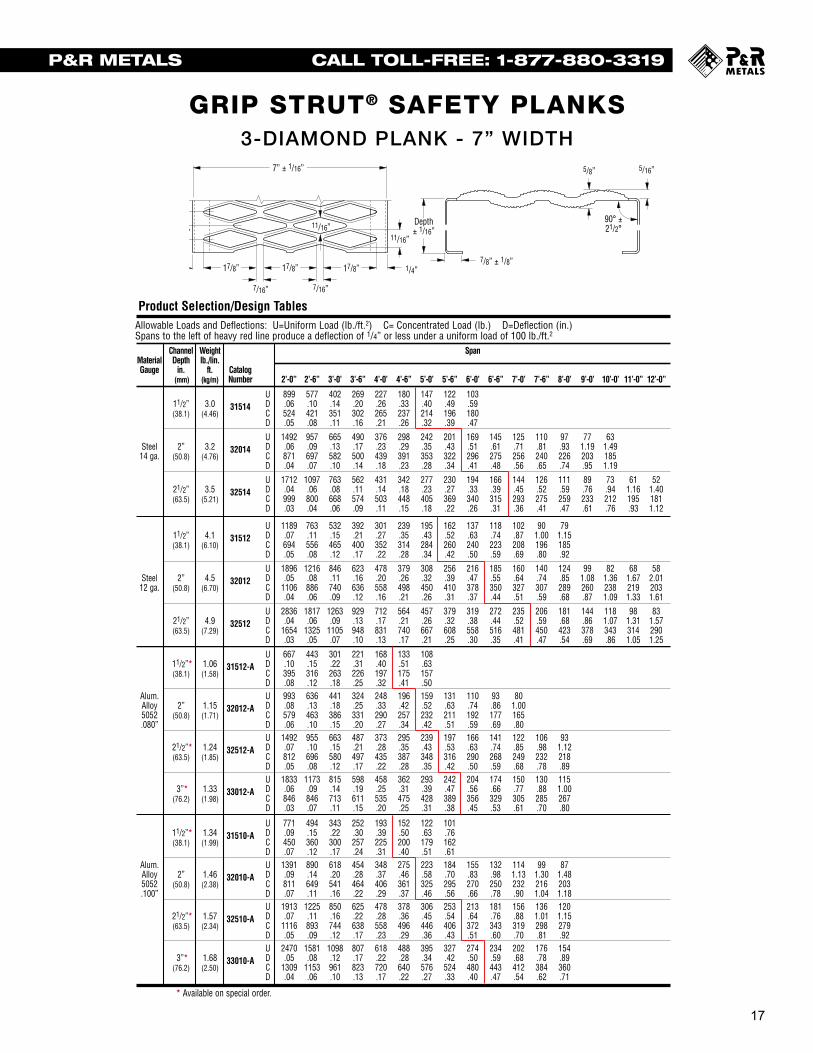
3-Diamond Plank __ 7” Width
Allowable Loads and Deflections: U=Uniform Load (lb./ft.2) C= Concentrated Load (lb.) D=Deflection (in.)Spans to the left of heavy red line produce a deflection of 1/4” or less under a uniform load of 100 lb./ft.2
Channel Weight SpanMaterial Depth lb./lin.Gauge in. ft. Catalog
(mm) (kg/m) Number 2’-0” 2’-6” 3’-0’ 3’-6” 4’-0’ 4’-6” 5’-0’ 5’-6” 6’-0’ 6’-6” 7’-0’ 7’-6” 8’-0’ 9’-0’ 10’-0’ 11’-0” 12’-0”
U 899 577 402 269 227 180 147 122 10311/2” 3.0 31514 D .06 .10 .14 .20 .26 .33 .40 .49 .59(38.1) (4.46) C 524 421 351 302 265 237 214 196 180
D .05 .08 .11 .16 .21 .26 .32 .39 .47
U 1492 957 665 490 376 298 242 201 169 145 125 110 97 77 63Steel 2” 3.2 32014 D .06 .09 .13 .17 .23 .29 .35 .43 .51 .61 .71 .81 .93 1.19 1.49
14 ga. (50.8) (4.76) C 871 697 582 500 439 391 353 322 296 275 256 240 226 203 185D .04 .07 .10 .14 .18 .23 .28 .34 .41 .48 .56 .65 .74 .95 1.19
U 1712 1097 763 562 431 342 277 230 194 166 144 126 111 89 73 61 5221/2” 3.5 32514 D .04 .06 .08 .11 .14 .18 .23 .27 .33 .39 .45 .52 .59 .76 .94 1.16 1.40(63.5) (5.21) C 999 800 668 574 503 448 405 369 340 315 293 275 259 233 212 195 181
D .03 .04 .06 .09 .11 .15 .18 .22 .26 .31 .36 .41 .47 .61 .76 .93 1.12
U 1189 763 532 392 301 239 195 162 137 118 102 90 7911/2” 4.1 31512 D .07 .11 .15 .21 .27 .35 .43 .52 .63 .74 .87 1.00 1.15(38.1) (6.10) C 694 556 465 400 352 314 284 260 240 223 208 196 185
D .05 .08 .12 .17 .22 .28 .34 .42 .50 .59 .69 .80 .92
U 1896 1216 846 623 478 379 308 256 216 185 160 140 124 99 82 68 58Steel 2” 4.5 32012 D .05 .08 .11 .16 .20 .26 .32 .39 .47 .55 .64 .74 .85 1.08 1.36 1.67 2.01
12 ga. (50.8) (6.70) C 1106 886 740 636 558 498 450 410 378 350 327 307 289 260 238 219 203D .04 .06 .09 .12 .16 .21 .26 .31 .37 .44 .51 .59 .68 .87 1.09 1.33 1.61
U 2836 1817 1263 929 712 564 457 379 319 272 235 206 181 144 118 98 8321/2” 4.9 32512 D .04 .06 .09 .13 .17 .21 .26 .32 .38 .44 .52 .59 .68 .86 1.07 1.31 1.57(63.5) (7.29) C 1654 1325 1105 948 831 740 667 608 558 516 481 450 423 378 343 314 290
D .03 .05 .07 .10 .13 .17 .21 .25 .30 .35 .41 .47 .54 .69 .86 1.05 1.25
U 3587 2298 1597 1174 900 712 578 478 403 344 297 259 228 181 148 123 10421/2” 5.2 33012 D .04 .06 .09 .13 .17 .21 .26 .32 .38 .44 .51 .59 .67 .86 1.07 1.30 1.55(63.5) (7.74) C 1868 1675 1397 1199 1050 935 843 767 705 652 606 567 533 476 431 395 364
D .03 .04 .06 .09 .11 .14 .18 .22 .26 .30 .35 .41 .46 .59 .73 .89 1.07
Product Selection/Design Tables
AllowableSpans to
MaterialGauge
Alum.Alloy5052.080”
Alum.Alloy5052.100”
Product
Engineering
MaterGaug
Steel14 ga.
Stee12 ga
Aluminu.080
Aluminu.100
5/16”5/8”
90° ±21/2°
Depth± 1/16”
7/8” ± 1/8”
9/16” 11/16”
11/16”
7/16” 7/16”
7” ± 1/16”
1/4” 1/4”
11/8”
17/8” 17/8” 17/8”
Grip Strut® Safe Loading Tables
12’-0”
521.401811.12
3-Diamond Plank __ 7” Width cont.
Allowable Loads and Deflections: U=Uniform Load (lb./ft.2) C= Concentrated Load (lb.) D=Deflection (in.)Spans to the left of heavy red line produce a deflection of 1/4” or less under a uniform load of 100 lb./ft.2
Channel Weight SpanMaterial Depth lb./lin.Gauge in. ft. Catalog
(mm) (kg/m) Number 2’-0” 2’-6” 3’-0’ 3’-6” 4’-0’ 4’-6” 5’-0’ 5’-6” 6’-0’ 6’-6” 7’-0’ 7’-6” 8’-0’ 8’-6’ 9’-0’ 9’-6” 10’-0”
U 667 443 301 221 168 133 10811/2”* 1.06 31512-A D .10 .15 .22 .31 .40 .51 .63(38.1) (1.58) C 395 316 263 226 197 175 157
D .08 .12 .18 .25 .32 .41 .50Alum. U 993 636 441 324 248 196 159 131 110 93 80Alloy 2” 1.15 32012-A D .08 .13 .18 .25 .33 .42 .52 .63 .74 .86 1.005052 (50.8) (1.71) C 579 463 386 331 290 257 232 211 192 177 165.080” D .06 .10 .15 .20 .27 .34 .42 .51 .59 .69 .80
U 1492 955 663 487 373 295 239 197 166 141 122 106 9321/2”* 1.24 32512-A D .07 .10 .15 .21 .28 .35 .43 .53 .63 .74 .85 .98 1.12(63.5) (1.85) C 812 696 580 497 435 387 348 316 290 268 249 232 218
D .05 .08 .12 .17 .22 .28 .35 .42 .50 .59 .68 .78 .89U 1833 1173 815 598 458 362 293 242 204 174 150 130 115
3”* 1.33 33012-A D .06 .09 .14 .19 .25 .31 .39 .47 .56 .66 .77 .88 1.00(76.2) (1.98) C 846 846 713 611 535 475 428 389 356 329 305 285 267
D .03 .07 .11 .15 .20 .25 .31 .38 .45 .53 .61 .70 .80
U 771 494 343 252 193 152 122 10111/2”* 1.34 31510-A D .09 .15 .22 .30 .39 .50 .63 .76(38.1) (1.99) C 450 360 300 257 225 200 179 162
D .07 .12 .17 .24 .31 .40 .51 .61Alum. U 1391 890 618 454 348 275 223 184 155 132 114 99 87Alloy 2” 1.46 32010-A D .09 .14 .20 .28 .37 .46 .58 .70 .83 .98 1.13 1.30 1.485052 (50.8) (2.38) C 811 649 541 464 406 361 325 295 270 250 232 216 203.100” D .07 .11 .16 .22 .29 .37 .46 .56 .66 .78 .90 1.04 1.18
U 1913 1225 850 625 478 378 306 253 213 181 156 136 12021/2”* 1.57 32510-A D .07 .11 .16 .22 .28 .36 .45 .54 .64 .76 .88 1.01 1.15(63.5) (2.34) C 1116 893 744 638 558 496 446 406 372 343 319 298 279
D .05 .09 .12 .17 .23 .29 .36 .43 .51 .60 .70 .81 .92U 2470 1581 1098 807 618 488 395 327 274 234 202 176 154
3”* 1.68 33010-A D .05 .08 .12 .17 .22 .28 .34 .42 .50 .59 .68 .78 .89(76.2) (2.50) C 1309 1153 961 823 720 640 576 524 480 443 412 384 360
D .04 .06 .10 .13 .17 .22 .27 .33 .40 .47 .54 .62 .71
Product Selection/Design Tables
* Available on special order.
Engineering Data For Both Channels
ChannelMaterial Depth- Sx Ix E IGauge in. in.3 in.4 lb. x in.2
Strut LoadingMaterial Type DeflectionGauge Loading** Load in.
Steel U 3535 .11
16”
3-DIAMOND PLANK - 7” WIDTH
16
Grip Strut® Safe Loading Tables3-Diamond Plank __ 7” Width
Allowable Loads and Deflections: U=Uniform Load (lb./ft.2) C= Concentrated Load (lb.) D=Deflection (in.)Spans to the left of heavy red line produce a deflection of 1/4” or less under a uniform load of 100 lb./ft.2
Channel Weight SpanMaterial Depth lb./lin.Gauge in. ft. Catalog
(mm) (kg/m) Number 2’-0” 2’-6” 3’-0’ 3’-6” 4’-0’ 4’-6” 5’-0’ 5’-6” 6’-0’ 6’-6” 7’-0’ 7’-6” 8’-0’ 9’-0’ 10’-0’ 11’-0” 12’-0”
U 899 577 402 269 227 180 147 122 10311/2” 3.0 31514 D .06 .10 .14 .20 .26 .33 .40 .49 .59(38.1) (4.46) C 524 421 351 302 265 237 214 196 180
D .05 .08 .11 .16 .21 .26 .32 .39 .47
U 1492 957 665 490 376 298 242 201 169 145 125 110 97 77 63Steel 2” 3.2 32014 D .06 .09 .13 .17 .23 .29 .35 .43 .51 .61 .71 .81 .93 1.19 1.49
14 ga. (50.8) (4.76) C 871 697 582 500 439 391 353 322 296 275 256 240 226 203 185D .04 .07 .10 .14 .18 .23 .28 .34 .41 .48 .56 .65 .74 .95 1.19
U 1712 1097 763 562 431 342 277 230 194 166 144 126 111 89 73 61 5221/2” 3.5 32514 D .04 .06 .08 .11 .14 .18 .23 .27 .33 .39 .45 .52 .59 .76 .94 1.16 1.40(63.5) (5.21) C 999 800 668 574 503 448 405 369 340 315 293 275 259 233 212 195 181
D .03 .04 .06 .09 .11 .15 .18 .22 .26 .31 .36 .41 .47 .61 .76 .93 1.12
U 1189 763 532 392 301 239 195 162 137 118 102 90 7911/2” 4.1 31512 D .07 .11 .15 .21 .27 .35 .43 .52 .63 .74 .87 1.00 1.15(38.1) (6.10) C 694 556 465 400 352 314 284 260 240 223 208 196 185
D .05 .08 .12 .17 .22 .28 .34 .42 .50 .59 .69 .80 .92
U 1896 1216 846 623 478 379 308 256 216 185 160 140 124 99 82 68 58Steel 2” 4.5 32012 D .05 .08 .11 .16 .20 .26 .32 .39 .47 .55 .64 .74 .85 1.08 1.36 1.67 2.01
12 ga. (50.8) (6.70) C 1106 886 740 636 558 498 450 410 378 350 327 307 289 260 238 219 203D .04 .06 .09 .12 .16 .21 .26 .31 .37 .44 .51 .59 .68 .87 1.09 1.33 1.61
U 2836 1817 1263 929 712 564 457 379 319 272 235 206 181 144 118 98 8321/2” 4.9 32512 D .04 .06 .09 .13 .17 .21 .26 .32 .38 .44 .52 .59 .68 .86 1.07 1.31 1.57(63.5) (7.29) C 1654 1325 1105 948 831 740 667 608 558 516 481 450 423 378 343 314 290
D .03 .05 .07 .10 .13 .17 .21 .25 .30 .35 .41 .47 .54 .69 .86 1.05 1.25
U 3587 2298 1597 1174 900 712 578 478 403 344 297 259 228 181 148 123 10421/2” 5.2 33012 D .04 .06 .09 .13 .17 .21 .26 .32 .38 .44 .51 .59 .67 .86 1.07 1.30 1.55(63.5) (7.74) C 1868 1675 1397 1199 1050 935 843 767 705 652 606 567 533 476 431 395 364
D .03 .04 .06 .09 .11 .14 .18 .22 .26 .30 .35 .41 .46 .59 .73 .89 1.07
Product Selection/Design Tables
AllowableSpans to
MaterialGauge
Alum.Alloy5052.080”
Alum.Alloy5052.100”
Product
Engineering
MateriGaug
Steel14 ga.
Stee12 ga
Aluminu.080
Aluminu.100
5/16”5/8”
90° ±21/2°
Depth± 1/16”
7/8” ± 1/8”
9/16” 11/16”
11/16”
7/16” 7/16”
7” ± 1/16”
1/4” 1/4”
11/8”
17/8” 17/8” 17/8”

18
P&R METALS CALL TOLL-FREE: 1-877-880-3319
GRIP STRUT® SAFETY PLANKS
18
Grip Strut® Safe Loading Tables4-Diamond Plank __ 91/2” Width (available in stainless steel)
Allowable Loads and Deflections: U=Uniform Load (lb./ft.2) C= Concentrated Load (lb.) D=Deflection (in.)Spans to the left of heavy red line produce a deflection of 1/4” or less under a uniform load of 100 lb./ft.2
Channel Weight SpanMaterial Depth lb./lin.Gauge in. ft. Catalog
(mm) (kg/m) Number 2’-0” 2’-6” 3’-0’ 3’-6” 4’-0’ 4’-6” 5’-0’ 5’-6” 6’-0’ 6’-6” 7’-0’ 7’-6” 8’-0’ 9’-0’ 10’-0’ 11’-0” 12’-0”
U 663 426 296 219 168 134 109 90 7711/2” 3.6 41514 D .06 .10 .14 .20 .26 .33 .41 .50 .59(38.1) (5.36) C 525 421 352 303 266 238 215 197 182
D .05 .08 .11 .16 .21 .26 .33 .40 .47
U 1100 705 491 362 278 220 179 148 125 107 93 81 72 58 47Steel 2” 3.8 42014 D .06 .09 .13 .17 .23 .29 .36 .43 .52 .61 .71 .82 .94 1.20 1.51
14 ga. (50.8) (5.65) C 730 698 583 501 440 392 354 323 298 276 258 242 228 205 187D .04 .07 .10 .14 .18 .23 .28 .35 .41 .49 .57 .66 .75 .96 1.20
U 1262 809 563 415 318 252 205 170 144 123 106 93 82 66 54 4521/2” 4.1 42514 D .04 .06 .08 .11 .14 .18 .23 .28 .33 .39 .45 .52 .60 .76 .95 1.17(63.5) (6.10) C 730 730 669 574 504 449 406 370 341 316 295 277 261 235 214 197
D .02 .04 .06 .09 .12 .15 .18 .22 .26 .31 .36 .42 .48 .61 .76 .94
U 906 581 405 298 229 182 148 123 104 89 77 67 6011/2” 5.0 41512 D .07 .11 .16 .21 .28 .36 .44 .54 .64 .76 .89 1.02 1.17(38.1) (7.44) C 718 575 481 413 363 324 292 267 246 228 213 200 189
D .06 .09 .13 .17 .23 .29 .35 .43 .52 .61 .71 .82 .94
U 1398 896 624 460 353 280 228 189 160 137 119 104 92 74 61 51 43Steel 2” 5.4 42012 D .05 .08 .11 .16 .20 .26 .32 .39 .47 .55 .65 .75 .85 1.10 1.38 1.69 2.03
12 ga. (50.8) (8.04) C 1107 887 741 637 559 499 451 412 380 353 329 309 292 264 241 222 206D .04 .06 .09 .12 .16 .21 .26 .31 .37 .44 .52 .60 .68 .88 1.10 1.35 1.63
U 2090 1339 931 685 525 416 338 280 236 201 174 152 134 107 87 73 6221/2” 5.7 42512 D .04 .06 .09 .13 .17 .21 .26 .32 .38 .44 .52 .60 .68 .87 1.08 1.32 1.58(63.5) (8.48) C 1400 1325 1106 949 832 741 668 609 559 518 482 452 425 380 345 316 293
D .03 .05 .07 .10 .13 .17 .21 .25 .30 .36 .41 .48 .54 .69 .86 1.05 1.27
U 2644 1694 1177 866 664 525 426 353 297 254 219 192 169 134 110 91 773” 6.1 43012 D .04 .06 .08 .11 .14 .18 .22 .27 .32 .38 .44 .51 .58 .74 .92 1.12 1.35
(76.2) (9.08) C 1400 1400 1398 1200 1051 936 844 769 706 653 608 569 535 478 434 397 367D .02 .04 .06 .09 .11 .15 .18 .22 .26 .31 .35 .41 .47 .59 .74 .90 1.08
Stain- U 720 462 322 238 183 145 118 98 83 71 59less 2” 3.2 42016-S D .05 .08 .11 .16 .20 .26 .32 .39 .47 .55 .61304 (50.8) (4.76) C 570 457 382 329 289 258 234 214 197 184 165
16 ga. D .04 .06 .09 .12 .16 .21 .26 .31 .38 .44 .49
Stain- U 626 400 278 204 156 123 100 82 69 59 51less 2” 3.2 42016-SL D .04 .06 .10 .13 .17 .22 .27 .32 .39 .45 .53316L (50.8) (4.76) C 492 397 330 283 248 220 198 180 165 152 14116 ga. D .03 .05 .08 .10 .14 .17 .22 .26 .31 .36 .42
Product Selection/Design Tables
5/16”5/8”
90° ±21/2°
Depth± 1/16”
7/8” ± 1/8”
9/16”11/16”
11/16”
7/16” 7/16”
91/2” ± 1/16”
11/32” 11/32”
11/8”
17/8” 17/8” 17/8”
Allowable Loads and Deflections:Spans to the left of heavy
Channel WeightMaterial Depth lb./lin.Gauge in. ft.
(mm) (kg/m) N
11/2”* .85 21512-A(38.1) (1.26)
Alum.Alloy 2” .92 22012-A5052 (50.8) (1.37).080”
21/2”* 1.00 22512-A(63.5) (1.48)
11/2”* 1.08 21510-A(38.1) (1.60)
Alum.Alloy 2” 1.20 22010-A5052 (50.8) (1.78).100”
21/2”* 1.31 22510-A(63.5) (1.95)
Product Selection/Design
* Available on
Engineering DataChannel
Material Depth-Gauge in.
Steel 11/2”
14 ga. 2”21/2
Steel 11/2”
12 ga. 2”21/2
Aluminum 11/2”
.080” 2”21/2
Aluminum 11/2”
.100” 2”21/2
Grip Strut® Safe Loading Tables4-Diamond Plank __ 91/2” Width cont.
Allowable Loads and Deflections: U=Uniform Load (lb./ft.2) C= Concentrated Load (lb.) D=Deflection (in.)Spans to the left of heavy red line produce a deflection of 1/4” or less under a uniform load of 100 lb./ft.2
Channel Weight SpanMaterial Depth lb./lin.Gauge in. ft. Catalog
(mm) (kg/m) Number 2’-0” 2’-6” 3’-0’ 3’-6” 4’-0’ 4’-6” 5’-0’ 5’-6” 6’-0’ 6’-6” 7’-0’ 7’-6” 8’-0’ 9’-0’ 10’-0’ 11’-0” 12’-0”
U 499 319 222 163 124 9811/2”* 1.28 41512-A D .10 .15 .22 .31 .40 .51(38.1) (1.90) C 395 316 263 226 197 175
D .08 .12 .18 .25 .32 .41Alum. U 732 468 325 239 183 145 117 97 81 69Alloy 2” 1.37 42012-A D .08 .13 .18 .25 .33 .42 .52 .63 .74 .875052 (50.8) (2.03) C 568 463 386 331 290 257 232 211 192 177.080” D .06 .10 .15 .20 .27 .34 .42 .51 .59 .69
U 1099 704 489 359 275 217 176 145 122 104 90 78 6921/2”* 1.46 42512-A D .07 .10 .15 .21 .28 .35 .43 .53 .63 .74 .85 .98 1.12(63.5) (2.17) C 568 568 568 497 435 387 348 316 290 268 249 232 218
D .05 .07 .12 .17 .22 .28 .35 .42 .50 .59 .68 .78 .89U 1350 864 600 441 338 267 216 179 150 128 110 96 84
3”* 1.55 43012-A D .06 .09 .14 .19 .25 .31 .39 .47 .56 .66 .77 .88 1.00(76.2) (2.30) C 568 568 568 568 535 475 428 389 356 329 305 285 267
D .02 .05 .09 .14 .20 .25 .31 .38 .45 .53 .61 .70 .80
U 568 364 253 186 142 11211/2”* 1.62 41510-A D .09 .15 .22 .30 .39 .50(38.1) (2.41) C 450 360 300 257 225 200
D .07 .12 .17 .24 .31 .40Alum. U 1025 656 455 335 256 202 164 136 114 97 84 73 64Alloy 2” 1.74 42010-A D .09 .14 .20 .28 .37 .46 .58 .70 .83 .98 1.13 1.30 1.485052 (50.8) (2.58) C 811 649 541 464 406 361 325 295 270 250 232 216 203.100” D .07 .11 .16 .22 .29 .37 .46 .56 .66 .78 .90 1.04 1.18
U 1410 902 627 460 352 278 226 186 157 133 115 100 8821/2”* 1.85 42510-A D .07 .11 .16 .22 .28 .36 .44 .54 .64 .76 .88 1.01 1.15(63.5) (2.75) C 886 886 744 638 558 496 446 406 372 343 319 298 279
D .05 .09 .12 .17 .23 .29 .36 .43 .51 .60 .70 .81 .92U 1820 1165 809 594 455 360 291 241 202 172 149 129 114
3”* 1.97 43010-A D .05 .08 .12 .17 .22 .28 .34 .42 .50 .59 .68 .78 .89(76.2) (2.93) C 886 886 886 823 720 640 576 524 480 443 412 384 360
D .02 .05 .09 .13 .17 .22 .27 .33 .40 .47 .54 .62 .71
Product Selection/Design Tables
* Available on special order.
Engineering Data For Both Channels
Material Channel Sx Ix E IGauge Depth-in. in.3 in.4 lb. x in.2
Steel 11/2” .174 .102 2.96 x 10⁶
2” .270 .193 5.60 x 10⁶
Strut LoadingMaterial Type DeflectionGauge Loading** Load in.
Steel U 1844 .15
9’-0’ 10’-0’ 11’-0” 12’-0”
113 931.18 1.47201 183.94 .1.18
5/16”
4-DIAMOND PLANK - 9 ½” WIDTH
18
Grip Strut® Safe Loading Tables4-Diamond Plank __ 91/2” Width (available in stainless steel)
Allowable Loads and Deflections: U=Uniform Load (lb./ft.2) C= Concentrated Load (lb.) D=Deflection (in.)Spans to the left of heavy red line produce a deflection of 1/4” or less under a uniform load of 100 lb./ft.2
Channel Weight SpanMaterial Depth lb./lin.Gauge in. ft. Catalog
(mm) (kg/m) Number 2’-0” 2’-6” 3’-0’ 3’-6” 4’-0’ 4’-6” 5’-0’ 5’-6” 6’-0’ 6’-6” 7’-0’ 7’-6” 8’-0’ 9’-0’ 10’-0’ 11’-0” 12’-0”
U 663 426 296 219 168 134 109 90 7711/2” 3.6 41514 D .06 .10 .14 .20 .26 .33 .41 .50 .59(38.1) (5.36) C 525 421 352 303 266 238 215 197 182
D .05 .08 .11 .16 .21 .26 .33 .40 .47
U 1100 705 491 362 278 220 179 148 125 107 93 81 72 58 47Steel 2” 3.8 42014 D .06 .09 .13 .17 .23 .29 .36 .43 .52 .61 .71 .82 .94 1.20 1.51
14 ga. (50.8) (5.65) C 730 698 583 501 440 392 354 323 298 276 258 242 228 205 187D .04 .07 .10 .14 .18 .23 .28 .35 .41 .49 .57 .66 .75 .96 1.20
U 1262 809 563 415 318 252 205 170 144 123 106 93 82 66 54 4521/2” 4.1 42514 D .04 .06 .08 .11 .14 .18 .23 .28 .33 .39 .45 .52 .60 .76 .95 1.17(63.5) (6.10) C 730 730 669 574 504 449 406 370 341 316 295 277 261 235 214 197
D .02 .04 .06 .09 .12 .15 .18 .22 .26 .31 .36 .42 .48 .61 .76 .94
U 906 581 405 298 229 182 148 123 104 89 77 67 6011/2” 5.0 41512 D .07 .11 .16 .21 .28 .36 .44 .54 .64 .76 .89 1.02 1.17(38.1) (7.44) C 718 575 481 413 363 324 292 267 246 228 213 200 189
D .06 .09 .13 .17 .23 .29 .35 .43 .52 .61 .71 .82 .94
U 1398 896 624 460 353 280 228 189 160 137 119 104 92 74 61 51 43Steel 2” 5.4 42012 D .05 .08 .11 .16 .20 .26 .32 .39 .47 .55 .65 .75 .85 1.10 1.38 1.69 2.03
12 ga. (50.8) (8.04) C 1107 887 741 637 559 499 451 412 380 353 329 309 292 264 241 222 206D .04 .06 .09 .12 .16 .21 .26 .31 .37 .44 .52 .60 .68 .88 1.10 1.35 1.63
U 2090 1339 931 685 525 416 338 280 236 201 174 152 134 107 87 73 6221/2” 5.7 42512 D .04 .06 .09 .13 .17 .21 .26 .32 .38 .44 .52 .60 .68 .87 1.08 1.32 1.58(63.5) (8.48) C 1400 1325 1106 949 832 741 668 609 559 518 482 452 425 380 345 316 293
D .03 .05 .07 .10 .13 .17 .21 .25 .30 .36 .41 .48 .54 .69 .86 1.05 1.27
U 2644 1694 1177 866 664 525 426 353 297 254 219 192 169 134 110 91 773” 6.1 43012 D .04 .06 .08 .11 .14 .18 .22 .27 .32 .38 .44 .51 .58 .74 .92 1.12 1.35
(76.2) (9.08) C 1400 1400 1398 1200 1051 936 844 769 706 653 608 569 535 478 434 397 367D .02 .04 .06 .09 .11 .15 .18 .22 .26 .31 .35 .41 .47 .59 .74 .90 1.08
Stain- U 720 462 322 238 183 145 118 98 83 71 59less 2” 3.2 42016-S D .05 .08 .11 .16 .20 .26 .32 .39 .47 .55 .61304 (50.8) (4.76) C 570 457 382 329 289 258 234 214 197 184 165
16 ga. D .04 .06 .09 .12 .16 .21 .26 .31 .38 .44 .49
Stain- U 626 400 278 204 156 123 100 82 69 59 51less 2” 3.2 42016-SL D .04 .06 .10 .13 .17 .22 .27 .32 .39 .45 .53316L (50.8) (4.76) C 492 397 330 283 248 220 198 180 165 152 14116 ga. D .03 .05 .08 .10 .14 .17 .22 .26 .31 .36 .42
Product Selection/Design Tables
5/16”5/8”
90° ±21/2°
Depth± 1/16”
7/8” ± 1/8”
9/16”11/16”
11/16”
7/16” 7/16”
91/2” ± 1/16”
11/32” 11/32”
11/8”
17/8” 17/8” 17/8”
AllowableSpans to
MaterialGauge
Alum.Alloy5052.080”
Alum.Alloy5052.100”
Product
Engineering
MaterGaug
Steel14 ga.
Steel12 ga.
Aluminum.080”
Aluminum.100”

19
P&R METALS CALL TOLL-FREE: 1-877-880-3319
GRIP STRUT® SAFETY PLANKS
20
Grip Strut® Safe Loading Tables5-Diamond Plank __ 113/4” Width (available in stainless steel)
Allowable Loads and Deflections: U=Uniform Load (lb./ft.2) C= Concentrated Load (lb.) D=Deflection (in.)Spans to the left of heavy red line produce a deflection of 1/4” or less under a uniform load of 100 lb./ft.2
Channel Weight SpanMaterial Depth lb./lin.Gauge in. ft. Catalog
(mm) (kg/m) Number 2’-0” 2’-6” 3’-0’ 3’-6” 4’-0’ 4’-6” 5’-0’ 5’-6” 6’-0’ 6’-6” 7’-0’ 7’-6” 8’-0’ 9’-0’ 10’-0’ 11’-0” 12’-0”
U 536 344 240 177 136 108 88 74 6211/2” 4.2 51514 D .06 .10 .14 .20 .26 .33 .41 .50 .60(38.1) (6.25) C 525 422 353 304 267 239 216 198 183
D .05 .08 .12 .16 .21 .26 .33 .40 .48
U 890 571 397 293 225 178 145 120 102 87 76 66 59 47Steel 2” 4.4 52014 D .06 .09 .13 .17 .23 .29 .36 .43 .52 .61 .71 .83 .95 1.21
14 ga. (50.8) (6.55) C 707 699 584 502 440 393 355 324 299 277 259 243 230 207D .04 .07 .10 .14 .18 .23 .29 .35 .42 .49 .57 .66 .76 .97
U 1021 655 456 336 258 204 166 138 116 100 86 76 67 54 4421/2” 4.7 52514 D .04 .06 .08 .11 .14 .18 .23 .28 .33 .39 .45 .52 .60 .77 .96(63.5) (6.99) C 707 707 669 575 505 450 407 371 342 317 296 278 262 236 216
D .02 .04 .06 .09 .12 .15 .18 .22 .26 .31 .36 .42 .48 .62 .77
U 710 456 318 235 181 144 117 98 83 71 62 55 4911/2” 5.9 51512 D .07 .11 .15 .21 .27 .35 .44 .53 .64 .76 .89 1.03 1.18(38.1) (8.78) C 695 558 467 402 354 317 287 263 244 227 213 201 190
D .05 .08 .12 .17 .22 .28 .35 .43 .51 .60 .71 .82 .95
U 1131 725 505 372 286 227 185 154 130 111 97 85 75 60 50 42Steel 2” 6.2 52012 D .05 .08 .11 .16 .20 .26 .32 .39 .47 .56 .65 .75 .86 1.11 1.39 1.70
12 ga. (50.8) (9.23) C 1107 888 742 638 561 501 453 414 382 355 332 312 295 266 243 224D .04 .06 .09 .12 .16 .21 .26 .31 .38 .44 .52 .60 .69 .89 1.11 1.36
U 1691 1083 753 554 425 337 273 226 151 141 123 109 87 71 59 59 5021/2” 6.6 52512 D .04 .06 .09 .13 .17 .21 .26 .32 .38 .45 .52 .60 .68 .87 1.09 1.33 1.60(63.5) (9.82) C 1115 1115 1106 950 833 742 669 610 561 519 484 453 426 382 347 319 295
D .02 .04 .07 .10 .13 .17 .21 .25 .30 .36 .41 .48 .55 .70 .87 1.06 1.28
U 2138 1370 952 701 537 425 345 286 241 206 178 155 137 109 89 74 633” 7.0 53012 D .04 .06 .08 .11 .14 .18 .22 .27 .32 .38 .44 .51 .58 .74 .93 1.13 1.36
(76.2) (10.40) C 1115 1115 1115 1115 1052 937 845 770 707 654 609 570 537 480 436 399 369D .02 .03 .05 .08 .11 .15 .18 .22 .26 .31 .36 .41 .47 .60 .74 .90 1.09
Stain- U 583 374 261 192 148 118 96 80 68 58 48less 2” 3.7 52016-S D .05 .08 .11 .16 .20 .26 .32 .39 .47 .56 .48304 (50.8) (5.51) C 464 458 323 330 290 259 235 215 199 185 165
16 ga. D .03 .06 .09 .12 .16 .21 .26 .32 .38 .45 .49
Stain- U 406 324 225 165 126 100 81 66 56 47less 2” 3.7 52016-SL D .04 .06 .10 .13 .17 .22 .27 .32 .39 .45316L (50.8) (5.51) C 398 397 330 283 248 220 198 180 165 15216 ga. D .03 .05 .08 .10 .14 .17 .22 .26 .31 .36
Product Selection/Design Tables
Load/Deflection Conversion Formulas
In the elastic range, deflection is proportionalto the applied load for both uniform andconcentrated loads. This relationship can beused to determine the deflection that any loadwhich is less than the allowable load willproduce, as shown in Example A. Also, ifdesired, the load which will produce a specificdeflection can also be determined if the load isin the elastic range as illustrated in Example B.
8- and 10-Diamond Allowable Load and Deflection TablesAs width increases, grating strut flexure becomes much moreimportant. 8- and 10-Diamond products are wide enough torequire a change in the assumptions used to prepare the2- through 5-Diamond Product Selection/Design Tables. Nolonger will it be assumed that both side channels are equallyeffective in supporting a concentrated load. In fact, to providea high level of safety, one side channel will be required tocarry 100% of a concentrated load.
Also strut deflection for 8- and 10-Diamond products may besignificant. The most critical case occurs when a concentratedload is located at mid-span and mid-width. To determine howthe struts perform under this loading, 3 foot long samples ofeach material and thickness were tested. For these tests theside channels were continuously supported and loads wereapplied using a 1 foot long and 1 inch wide bar placed parallelto the side channels at mid-width and at the longitudinal center.
Results of these tests, included in the 8- and 10-DiamondProduct Design Tables, proved the performance of thesematerials when a concentrated load is applied at mid-spanand mid-width. If a concentrated load is to be applied at mid-width at the end of a plank, consult the “strut loading” table.
The following values have been tabulated for 8- and 10-Diamond grating:
Figure 2a Strut Load
D
Load - Cs
5/16”5/8”
90° ±21/2°
Depth± 1/16”
7/8” ± 1/8”
9/16”11/16”
11/16”
7/16” 7/16”
113/4” ± 1/16”
5/16” 5/16”
11/8”
17/8” 17/8” 17/8”
Grip Strut® Safe Loading Tables5-Diamond Plank __ 113/4” Width cont.
Allowable Loads and Deflections: U=Uniform Load (lb./ft.2) C= Concentrated Load (lb.) D=Deflection (in.)Spans to the left of heavy red line produce a deflection of 1/4” or less under a uniform load of 100 lb./ft.2
Channel Weight SpanMaterial Depth lb./lin.Gauge in. ft. Catalog
(mm) (kg/m) Number 2’-0” 2’-6” 3’-0’ 3’-6” 4’-0’ 4’-6” 5’-0’ 5’-6” 6’-0’ 6’-6” 7’-0’ 7’-6” 8’-0’ 9’-0’ 10’-0’ 11’-0” 12’-0”
U 403 255 179 132 10011/2”* 1.49 51512-A D .10 .15 .22 .31 .40(38.1) (2.22) C 395 316 263 226 197
D .08 .12 .18 .25 .32Alum. U 592 379 263 193 148 117 95 78Alloy 2” 1.59 52012-A D .08 .13 .18 .25 .33 .42 .52 .635052 (50.8) (2.36) C 466 466 386 331 290 257 232 211.080” D .05 .10 .15 .20 .27 .34 .42 .51
U 889 569 395 290 222 176 142 118 99 84 73 6321/2”* 1.67 52512-A D .07 .10 .15 .21 .28 .35 .43 .53 .63 .74 .85 .98(63.5) (2.48) C 466 466 466 466 435 387 348 316 290 268 249 232
D .02 .05 .10 .16 .22 .28 .35 .42 .50 .59 .68 .78U 951 699 485 357 273 216 175 144 121 103 89 78 68
3”* 1.75 53012-A D .05 .09 .14 .19 .25 .31 .39 .47 .56 .66 .77 .88 1.00(76.2) (2.60) C 466 466 466 466 466 466 428 389 356 329 305 285 267
D .02 .04 .07 .11 .17 .24 .31 .38 .45 .53 .61 .70 .80
U 459 294 204 150 115 9111/2”* 1.88 51510-A D .09 .15 .22 .30 .39 .50(38.1) (2.79) C 450 360 300 257 225 200
D .07 .12 .17 .24 .31 .40Alum. U 829 530 368 271 207 164 133 110 92 78 68 59Alloy 2” 2.00 52010-A D .09 .14 .20 .28 .37 .46 .58 .70 .83 .98 1.13 1.305052 (50.8) (2.98) C 714 649 541 464 406 361 325 295 270 250 232 216.100” D .06 .11 .16 .22 .29 .37 .46 .56 .66 .78 .90 1.04
U 1140 730 507 372 285 225 182 151 127 105 93 81 7121/2”* 2.11 52510-A D .07 .11 .16 .22 .28 .36 .45 .54 .64 .76 .88 1.01 1.15(63.5) (3.14) C 714 714 714 638 558 496 446 406 372 343 319 298 279
D .03 .07 .12 .17 .23 .29 .36 .43 .51 .60 .70 .81 .92U 1458 942 654 481 368 291 235 195 164 139 120 105 92
3”* 2.22 53010-A D .05 .08 .12 .17 .22 .28 .34 .42 .50 .59 .68 .78 .89(76.2) (3.30) C 714 714 714 714 714 640 576 524 280 443 412 384 360
D .02 .04 .07 .12 .17 .22 .27 .33 .40 .47 .54 .62 .71
Product Selection/Design Tables
* Available on special order.
Engineering Data For Both Channels
Material Channel Sx Ix E IGauge Depth-in. in.3 in.4 lb. x in.2
Steel 11/2” .174 .102 2.96 x 10⁶
14 ga. 2” .270 .193 5.60 x 10⁶
21/ .307 .335 9.71 x 10⁶
Strut LoadingMaterial Type DeflectionGauge Loading** Load in.
Steel U 1444 .1814 ga. Cs 707 .15
flexure. This occurs when the channels at mid-span of the plankdeflect relative to support points. To verify the performance ofthe side channels, samples were loaded with concentrated anduniform loads at different spans (see Figures 1b/2b and 1c/2c).To approximate the most severe condition, there were noattachments between the channels and the supports. In caseswhere spans are shorter, channels deeper and planks wider,
2-, 3-, 4- and 5-Diamond Allowable Load and
Since 2- through 5-Diamond planks are relatively narrow (lessthan 1 foot wide), it can be assumed that both side channelseffectively support the concentrated load and that the gratingsurface deflection is negligible. Based upon these assumption,the values in the following Design Tables for 2- through 5-
Values indicated in the rows adjacent to “U” are the lowest ofthe (1) maximum allowable uniform loads considering channelflexure and (2) maximum grating surface flexure.
Deflection values are indicated below the uniform loads and arein the mid-span side channel deflections for the planks carryingthe allowable uniform loads (Figure 1c and 2c).
Values indicated in the rows labeled “C” are the lowest of the(1) maximum allowable concentrated load considering channelflexure (Figure 1b and 2b), with both channels effective, and (2)
s) for a 1 foot long sample
Deflection values indicated below “C” values in the tables arethe mid-span, side channel deflections produced when theallowable concentrated load is placed at mid-span.If grating surface deflection should be considered whenselecting a product to meet a particular specification, then thedeflection of the mid-width of the grating, relative to the sidechannels, can be calculated using both the data in the StrutLoading Tables and the Load/Deflection Conversion formula
Load data based on yield strength of 33,000 psi for steel,23,000 psi for aluminum, 35,000 psi for Type 304 stainlesssteel, and 30,000 psi for Type 316L stainless steel.
5-DIAMOND PLANK - 11 ¾” WIDTH
20
Grip Strut® Safe Loading Tables5-Diamond Plank __ 113/4” Width (available in stainless steel)
Allowable Loads and Deflections: U=Uniform Load (lb./ft.2) C= Concentrated Load (lb.) D=Deflection (in.)Spans to the left of heavy red line produce a deflection of 1/4” or less under a uniform load of 100 lb./ft.2
Channel Weight SpanMaterial Depth lb./lin.Gauge in. ft. Catalog
(mm) (kg/m) Number 2’-0” 2’-6” 3’-0’ 3’-6” 4’-0’ 4’-6” 5’-0’ 5’-6” 6’-0’ 6’-6” 7’-0’ 7’-6” 8’-0’ 9’-0’ 10’-0’ 11’-0” 12’-0”
U 536 344 240 177 136 108 88 74 6211/2” 4.2 51514 D .06 .10 .14 .20 .26 .33 .41 .50 .60(38.1) (6.25) C 525 422 353 304 267 239 216 198 183
D .05 .08 .12 .16 .21 .26 .33 .40 .48
U 890 571 397 293 225 178 145 120 102 87 76 66 59 47Steel 2” 4.4 52014 D .06 .09 .13 .17 .23 .29 .36 .43 .52 .61 .71 .83 .95 1.21
14 ga. (50.8) (6.55) C 707 699 584 502 440 393 355 324 299 277 259 243 230 207D .04 .07 .10 .14 .18 .23 .29 .35 .42 .49 .57 .66 .76 .97
U 1021 655 456 336 258 204 166 138 116 100 86 76 67 54 4421/2” 4.7 52514 D .04 .06 .08 .11 .14 .18 .23 .28 .33 .39 .45 .52 .60 .77 .96(63.5) (6.99) C 707 707 669 575 505 450 407 371 342 317 296 278 262 236 216
D .02 .04 .06 .09 .12 .15 .18 .22 .26 .31 .36 .42 .48 .62 .77
U 710 456 318 235 181 144 117 98 83 71 62 55 4911/2” 5.9 51512 D .07 .11 .15 .21 .27 .35 .44 .53 .64 .76 .89 1.03 1.18(38.1) (8.78) C 695 558 467 402 354 317 287 263 244 227 213 201 190
D .05 .08 .12 .17 .22 .28 .35 .43 .51 .60 .71 .82 .95
U 1131 725 505 372 286 227 185 154 130 111 97 85 75 60 50 42Steel 2” 6.2 52012 D .05 .08 .11 .16 .20 .26 .32 .39 .47 .56 .65 .75 .86 1.11 1.39 1.70
12 ga. (50.8) (9.23) C 1107 888 742 638 561 501 453 414 382 355 332 312 295 266 243 224D .04 .06 .09 .12 .16 .21 .26 .31 .38 .44 .52 .60 .69 .89 1.11 1.36
U 1691 1083 753 554 425 337 273 226 151 141 123 109 87 71 59 59 5021/2” 6.6 52512 D .04 .06 .09 .13 .17 .21 .26 .32 .38 .45 .52 .60 .68 .87 1.09 1.33 1.60(63.5) (9.82) C 1115 1115 1106 950 833 742 669 610 561 519 484 453 426 382 347 319 295
D .02 .04 .07 .10 .13 .17 .21 .25 .30 .36 .41 .48 .55 .70 .87 1.06 1.28
U 2138 1370 952 701 537 425 345 286 241 206 178 155 137 109 89 74 633” 7.0 53012 D .04 .06 .08 .11 .14 .18 .22 .27 .32 .38 .44 .51 .58 .74 .93 1.13 1.36
(76.2) (10.40) C 1115 1115 1115 1115 1052 937 845 770 707 654 609 570 537 480 436 399 369D .02 .03 .05 .08 .11 .15 .18 .22 .26 .31 .36 .41 .47 .60 .74 .90 1.09
Stain- U 583 374 261 192 148 118 96 80 68 58 48less 2” 3.7 52016-S D .05 .08 .11 .16 .20 .26 .32 .39 .47 .56 .48304 (50.8) (5.51) C 464 458 323 330 290 259 235 215 199 185 165
16 ga. D .03 .06 .09 .12 .16 .21 .26 .32 .38 .45 .49
Stain- U 406 324 225 165 126 100 81 66 56 47less 2” 3.7 52016-SL D .04 .06 .10 .13 .17 .22 .27 .32 .39 .45316L (50.8) (5.51) C 398 397 330 283 248 220 198 180 165 15216 ga. D .03 .05 .08 .10 .14 .17 .22 .26 .31 .36
Product Selection/Design Tables
Load/Deflection Conversion Formulas
In the elastic range, deflection is proportionalto the applied load for both uniform andconcentrated loads. This relationship can beused to determine the deflection that any loadwhich is less than the allowable load willproduce, as shown in Example A. Also, ifdesired, the load which will produce a specificdeflection can also be determined if the load isin the elastic range as illustrated in Example B.
8- and 10-Diamond Allowable Load and Deflection TablesAs width increases, grating strut flexure becomes much moreimportant. 8- and 10-Diamond products are wide enough torequire a change in the assumptions used to prepare the2- through 5-Diamond Product Selection/Design Tables. Nolonger will it be assumed that both side channels are equallyeffective in supporting a concentrated load. In fact, to providea high level of safety, one side channel will be required tocarry 100% of a concentrated load.
Also strut deflection for 8- and 10-Diamond products may besignificant. The most critical case occurs when a concentratedload is located at mid-span and mid-width. To determine howthe struts perform under this loading, 3 foot long samples ofeach material and thickness were tested. For these tests theside channels were continuously supported and loads wereapplied using a 1 foot long and 1 inch wide bar placed parallelto the side channels at mid-width and at the longitudinal center.
Results of these tests, included in the 8- and 10-DiamondProduct Design Tables, proved the performance of thesematerials when a concentrated load is applied at mid-spanand mid-width. If a concentrated load is to be applied at mid-width at the end of a plank, consult the “strut loading” table.
The following values have been tabulated for 8- and 10-Diamond grating:
Figure 2a Strut Load
D
5/16”5/8”
90° ±21/2°
Depth± 1/16”
7/8” ± 1/8”
9/16”11/16”
11/16”
7/16” 7/16”
113/4” ± 1/16”
5/16” 5/16”
11/8”
17/8” 17/8” 17/8”

20
P&R METALS CALL TOLL-FREE: 1-877-880-3319
GRIP STRUT® SAFETY PLANKS
22
8-Diamond Plank __ 183/4” Width
Allowable Loads and Deflections: U=Uniform Load (lb./ft.2) C= Concentrated Load (lb.) D=Deflection (in.)Spans to the left of heavy red line produce a deflection of 1/4” or less under a uniform load of 100 lb./ft.2
Channel Weight SpanMaterial Depth lb./lin.Gauge in. ft. Catalog
(mm) (kg/m) Number 2’-0” 2’-6” 3’-0’ 3’-6” 4’-0’ 4’-6” 5’-0’ 5’-6” 6’-0’ 6’-6” 7’-0’ 7’-6” 8’-0’ 9’-0’ 10’-0’ 11’-0” 12’-0”
U 337 217 151 112 86 69 56 4711/2” 6.1 81514 D .33 .27 .26 .29 .33 .38 .45 .55(38.1) (9.1) C 263 211 178 153 135 121 110 101
D .16 .15 .15 .16 .17 .19 .22 .25
U 540 358 250 184 142 113 92 76 65 55 48 42Steel 2” 6.3 82014 D .48 .37 .34 .32 .34 .38 .43 .50 .58 .66 .77 .87
14 ga. (50.8) (9.4) C 437 349 292 251 220 198 179 164 152 141 132 124D .24 .21 .20 .19 .20 .21 .23 .26 .29 .32 .36 .40
U 540 411 286 211 162 129 105 87 74 63 56 48 4321/2” 6.6 82514 D .46 .39 .35 .28 .27 .28 .31 .35 .39 .44 .50 .57 .64(63.5) (9.8) C 450 402 335 287 252 225 205 188 173 161 151 142 134
D .24 .22 .20 .19 .19 .19 .20 .21 .23 .24 .27 .29 .32
U 446 287 201 148 115 91 75 63 53 46 4011/2” 8.5 81512 D .27 .22 .22 .26 .32 .39 .47 .56 .67 .80 .92(38.1) (12.6) C 359 280 235 203 179 161 146 135 125 117 110
D .12 .12 .12 .14 .16 .19 .22 .26 .30 .35 .40
U 710 456 318 235 181 144 117 98 83 71 62 54 48Steel 2” 8.9 82012 D .31 .25 .23 .25 .28 .31 .37 .44 .51 .60 .68 .79 .90
12 ga. (50.8) (13.2) C 554 444 371 319 282 253 229 210 194 181 169 160 151D .17 .15 .14 .15 .16 .17 .19 .22 .25 .28 .32 .36 .40
U 810 680 473 348 267 212 172 143 120 103 89 78 69 55 4521/2” 9.2 82512 D .33 .31 .27 .26 .27 .29 .32 .37 .42 .49 .55 .63 .72 .90 1.12(63.5) (13.7) C 800 663 553 475 416 371 334 307 282 262 244 229 216 194 177
D .23 .20 .18 .18 .18 .18 .19 .21 .23 .25 .28 .31 .34 .41 .50
U 810 810 598 440 337 267 217 180 152 130 112 98 87 69 57 47 4021/2” 9.6 83012 D .32 .35 .30 .27 .26 .28 .31 .34 .39 .43 .49 .56 .62 .78 .96 1.17 1.40(63.5) (14.3) C 800 800 699 600 526 468 422 385 353 327 307 288 271 243 221 203 189
D .22 .23 .22 .20 .20 .20 .20 .21 .22 .24 .26 .28 .31 .37 .44 .52 .61
Product Selection/Design Tables
Splice Plate Package — 7 inchPackage (cat. no. SP-10DU-7) includes:Two (2) 8-hole 10 gauge 4” x 7” splice plates, and sixteen (16) each x 11/4” hex head cap screws (galv. S.A.E. Grade 5, lightly oiled), washersand hex nuts. Kit joins continuous sections together in a run only oversupports.
Note: Contact factory for information on pre-punched holes in grating.
Recommended Bolt Torque -
Splice Plate Kit — 30 inchPackage (cat. no. SP-10DU-30) includes:Two (2) 8-hole 12 gauge 41/2” x 30” C-channel splice plates, and sixteen(16) each sections together in a run over clear spans to act as one continuous unit.Any combination or 12’-0” and 10’-0” planks can be joined with spliceplate package.
Note: Contact factory for information on pre-punched holes in grating.
Recommended Bolt Torque -
5/16”5/8”
90° ±21/2°
Depth± 1/16”
7/8” ± 1/8”
9/16”11/16”
11/16”
7/16” 7/16”
183/4” ± 1/16”
11/32” 11/32”
11/8”
17/8” 17/8” 17/8”
Grip Strut® Safe Loading Tables
Allowable Loads and Deflections: U=Uniform Load (lb./ft.2) C= Concentrated Load (lb.) D=Deflection (in.)Spans to the left of heavy red line produce a deflection of 1/4” or less under a uniform load of 100 lb./ft.2
Channel Weight SpanMaterial Depth lb./lin.Gauge in. ft. Catalog
(mm) (kg/m) Number 2’-0” 2’-6” 3’-0’ 3’-6” 4’-0’ 4’-6” 5’-0’ 5’-6” 6’-0’ 6’-6” 7’-0’ 7’-6” 8’-0’ 9’-0’ 10’-0’ 11’-0” 12’-0”
U 253 162 112 8311/2”* 2.11 81512-A D .49 .40 .39 .44(38.1) (3.13) C 198 158 132 113
D .24 .22 .22 .24Alum. U 308 237 165 121 93 73 59 49Alloy 2” 2.20 82012-A D .54 .50 .44 .44 .47 .53 .61 .715052 (50.8) (3.27) C 290 232 193 166 145 129 116 106.080” D .32 .28 .27 .27 .28 .30 .32 .36
U 308 308 248 182 139 110 89 74 62 5321/2”* 2.29 82512-A D .51 .57 .54 .49 .50 .52 .57 .65 .73 .83(63.5) (3.40) C 350 348 290 249 218 194 174 158 145 134
D .37 .39 .35 .33 .33 .34 .35 .37 .40 .43U 308 308 308 223 171 135 109 90 76 65 56 49
3”* 2.39 83012-A D .50 .54 .62 .54 .52 .52 .56 .61 .68 .76 .86 .96(76.2) (3.55) C 350 350 350 306 268 238 214 195 178 165 153 143
D .37 .38 .41 .38 .37 .37 .37 .39 .40 .43 .46 .50
U 288 184 128 94 72 5711/2”* 2.68 81510-A D .41 .36 .36 .40 .47 .56(38.1) (3.98) C 225 180 150 129 113 100
D .18 .18 .19 21 .23 .27Alum. U 457 332 231 170 130 103 83 69 58 49Alloy 2” 2.79 82010-A D .59 .51 .46 .47 .52 .57 .67 .78 .89 1.035052 (50.8) (4.15) C 406 325 271 232 203 181 163 148 135 125.100” D .29 .26 .25 .26 .28 .30 .33 .37 .42 .47
U 457 457 317 233 179 141 114 94 79 68 58 51 4521/2”* 2.91 82510-A D .55 .62 .51 .48 .48 .52 .58 .64 .73 .84 .94 1.07 1.20(63.5) (4.33) C 550 447 372 319 279 248 223 203 186 172 160 149 140
D .37 .32 .30 .29 .29 .30 .32 .35 .38 .41 .46 .52 .55U 457 457 410 301 231 182 148 122 102 87 75 66 58
3”* 3.02 83010-A D .53 .57 .58 .51 .48 .48 .51 .56 .61 .69 .76 .85 .95(76.2) (4.50) C 550 550 481 412 360 320 288 262 240 222 206 192 180
D .37 .39 .37 .35 .34 .34 .36 .38 .41 .44 .48 .52 .57
Product Selection/Design Tables
* Available on special order.
Engineering Data For Both Channels
ChannelMaterial Depth- Sx Ix E IGauge in. in.3 in.4 lb. x in.2
Strut LoadingMaterial Type DeflectionGauge Loading** Load in.
8-Diamond Plank __ 183/4” Width cont.
Diamond Anchor cat. no. 12262 isshaped to fit in diamond opening.
” carriagehead bolt with square shank. Doesnot include bolts, nuts or washers.
galvanized before fabrication. Alsoavailable in 304 stainless steel.
8-DIAMOND PLANK - 18 ¾” WIDTH
22
Grip Strut® Safe Loading Tables8-Diamond Plank __ 183/4” Width
Allowable Loads and Deflections: U=Uniform Load (lb./ft.2) C= Concentrated Load (lb.) D=Deflection (in.)Spans to the left of heavy red line produce a deflection of 1/4” or less under a uniform load of 100 lb./ft.2
Channel Weight SpanMaterial Depth lb./lin.Gauge in. ft. Catalog
(mm) (kg/m) Number 2’-0” 2’-6” 3’-0’ 3’-6” 4’-0’ 4’-6” 5’-0’ 5’-6” 6’-0’ 6’-6” 7’-0’ 7’-6” 8’-0’ 9’-0’ 10’-0’ 11’-0” 12’-0”
U 337 217 151 112 86 69 56 4711/2” 6.1 81514 D .33 .27 .26 .29 .33 .38 .45 .55(38.1) (9.1) C 263 211 178 153 135 121 110 101
D .16 .15 .15 .16 .17 .19 .22 .25
U 540 358 250 184 142 113 92 76 65 55 48 42Steel 2” 6.3 82014 D .48 .37 .34 .32 .34 .38 .43 .50 .58 .66 .77 .87
14 ga. (50.8) (9.4) C 437 349 292 251 220 198 179 164 152 141 132 124D .24 .21 .20 .19 .20 .21 .23 .26 .29 .32 .36 .40
U 540 411 286 211 162 129 105 87 74 63 56 48 4321/2” 6.6 82514 D .46 .39 .35 .28 .27 .28 .31 .35 .39 .44 .50 .57 .64(63.5) (9.8) C 450 402 335 287 252 225 205 188 173 161 151 142 134
D .24 .22 .20 .19 .19 .19 .20 .21 .23 .24 .27 .29 .32
U 446 287 201 148 115 91 75 63 53 46 4011/2” 8.5 81512 D .27 .22 .22 .26 .32 .39 .47 .56 .67 .80 .92(38.1) (12.6) C 359 280 235 203 179 161 146 135 125 117 110
D .12 .12 .12 .14 .16 .19 .22 .26 .30 .35 .40
U 710 456 318 235 181 144 117 98 83 71 62 54 48Steel 2” 8.9 82012 D .31 .25 .23 .25 .28 .31 .37 .44 .51 .60 .68 .79 .90
12 ga. (50.8) (13.2) C 554 444 371 319 282 253 229 210 194 181 169 160 151D .17 .15 .14 .15 .16 .17 .19 .22 .25 .28 .32 .36 .40
U 810 680 473 348 267 212 172 143 120 103 89 78 69 55 4521/2” 9.2 82512 D .33 .31 .27 .26 .27 .29 .32 .37 .42 .49 .55 .63 .72 .90 1.12(63.5) (13.7) C 800 663 553 475 416 371 334 307 282 262 244 229 216 194 177
D .23 .20 .18 .18 .18 .18 .19 .21 .23 .25 .28 .31 .34 .41 .50
U 810 810 598 440 337 267 217 180 152 130 112 98 87 69 57 47 4021/2” 9.6 83012 D .32 .35 .30 .27 .26 .28 .31 .34 .39 .43 .49 .56 .62 .78 .96 1.17 1.40(63.5) (14.3) C 800 800 699 600 526 468 422 385 353 327 307 288 271 243 221 203 189
D .22 .23 .22 .20 .20 .20 .20 .21 .22 .24 .26 .28 .31 .37 .44 .52 .61
Product Selection/Design Tables
Splice Plate Package — 7 inchPackage (cat. no. SP-10DU-7) includes:Two (2) 8-hole 10 gauge 4” x 7” splice plates, and sixteen (16) each x 11/4and hex nuts. Kit joins continuous sections together in a run only oversupports.
Note: Contact factory for information on pre-punched holes in grating.
Recommended Bolt Torque -
Splice Plate Kit — 30 inchPackage (cat. no. SP-10DU-30) includes:Two (2) 8-hole 12 gauge 41/2” x 30” C-channel splice plates, and sixteen(16) each sections together in a run over clear spans to act as one continuous unit.Any combination or 12’-0” and 10’-0” planks can be joined with spliceplate package.
Note: Contact factory for information on pre-punched holes in grating.
Recommended Bolt Torque -
5/16”5/8”
90° ±21/2°
Depth± 1/16”
7/8” ± 1/8”
9/16”11/16”
11/16”
7/16” 7/16”
183/4” ± 1/16”
11/32” 11/32”
11/8”
17/8” 17/8” 17/8”

21
P&R METALS CALL TOLL-FREE: 1-877-880-3319
GRIP STRUT® SAFETY PLANKS
24
Allowable Loads and Deflections: U=Uniform Load (lb./ft.2) C= Concentrated Load (lb.) D=Deflection (in.)Spans to the left of heavy red line produce a deflection of 1/4” or less under a uniform load of 100 lb./ft.2
Channel Weight SpanMaterial Depth lb./lin.Gauge in. ft. Catalog
(mm) (kg/m) Number 2’-0” 2’-6” 3’-0’ 3’-6” 4’-0’ 4’-6” 5’-0’ 5’-6” 6’-0’ 6’-6” 7’-0’ 7’-6” 8’-0’ 9’-0’ 10’-0’ 11’-0” 12’-0”
U 300 300 228 168 128 102 82 68 57 49 422” 7.4 102014 D .46 .48 .42 .38 .38 .41 .44 .49 .55 .62 .70
(50.8) (11.0) C 400 400 343 294 257 229 206 187 172 158 147Steel D .34 .35 .32 .30 .29 .29 .30 .31 .33 .35 .37
14 ga. U 300 300 300 264 202 160 130 107 90 77 66 58 51 403” 7.9 103014 D .42 .43 .46 .44 .39 .36 .35 .36 .39 .44 .45 .49 .54 .65
(76.2) (11.8) C 400 400 400 400 400 360 324 295 270 249 232 216 203 180D .33 .33 .34 .35 .37 .35 .33 .33 .32 .32 .33 .34 .35 .38
U 475 416 289 212 162 128 104 86 72 62 53 462” 19.4 102012 D .40 .39 .33 .31 .31 .34 .38 .44 .48 .56 .63 .71
(50.8) (15.5) C 650 520 434 372 325 289 260 237 217 200 186 174Steel D .26 .22 .19 .20 .20 .21 .22 .23 .25 .28 .31 .34
12 ga. U 475 475 475 392 300 237 192 159 133 114 98 85 75 59 483” 11.1 103012 D .38 .39 .42 .38 .36 .34 .35 .37 .39 .43 .47 .52 .58 .70 .85
(76.2) (16.5) C 900 900 800 686 600 534 480 437 400 369 343 320 300 267 240D .34 .35 .33 .29 .27 .26 .26 .26 .26 .27 .29 .30 .32 .36 .41
Product Selection/Design Tables
Engineering Data For Both Channels
ChannelMaterial Depth- Sx Ix E IGauge in. in.3 in.4 lb. x in.2
Steel 2” .303 .232 6.73 x 10⁶
14 ga. 3” .484 .713 20.68 x 10⁶
Steel 2” .387 .346 10.03 x 10⁶
12 ga. 3” .715 .959 27.81 x 10⁶
Strut LoadingMaterial Type DeflectionGauge Loading** Load in.
Steel U 300 .4914 ga. Cs 300 .40
Steel U 475 .4512 ga. Cs 475 .36
** U = Allowable Uniform Load (lb./ft.2)Cs = Allowable Concentrated Load per ft. of length at mid-width (lb./ft.)
5/16”5/8”
90° ±21/2°
Depth± 1/16”
7/8” ± 1/8”
9/16”11/16”
11/16”
7/16” 7/16”
24” ± 1/16”
21/32” 21/32”
11/8”
17/8” 17/8” 17/8”
10-DIAMOND PLANK - 24” WIDTH
24
10-Diamond Plank __ 24” Width
Allowable Loads and Deflections: U=Uniform Load (lb./ft.2) C= Concentrated Load (lb.) D=Deflection (in.)Spans to the left of heavy red line produce a deflection of 1/4” or less under a uniform load of 100 lb./ft.2
Channel Weight SpanMaterial Depth lb./lin.Gauge in. ft. Catalog
(mm) (kg/m) Number 2’-0” 2’-6” 3’-0’ 3’-6” 4’-0’ 4’-6” 5’-0’ 5’-6” 6’-0’ 6’-6” 7’-0’ 7’-6” 8’-0’ 9’-0’ 10’-0’ 11’-0” 12’-0”
U 300 300 228 168 128 102 82 68 57 49 422” 7.4 102014 D .46 .48 .42 .38 .38 .41 .44 .49 .55 .62 .70
(50.8) (11.0) C 400 400 343 294 257 229 206 187 172 158 147Steel D .34 .35 .32 .30 .29 .29 .30 .31 .33 .35 .37
14 ga. U 300 300 300 264 202 160 130 107 90 77 66 58 51 403” 7.9 103014 D .42 .43 .46 .44 .39 .36 .35 .36 .39 .44 .45 .49 .54 .65
(76.2) (11.8) C 400 400 400 400 400 360 324 295 270 249 232 216 203 180D .33 .33 .34 .35 .37 .35 .33 .33 .32 .32 .33 .34 .35 .38
U 475 416 289 212 162 128 104 86 72 62 53 462” 19.4 102012 D .40 .39 .33 .31 .31 .34 .38 .44 .48 .56 .63 .71
(50.8) (15.5) C 650 520 434 372 325 289 260 237 217 200 186 174Steel D .26 .22 .19 .20 .20 .21 .22 .23 .25 .28 .31 .34
12 ga. U 475 475 475 392 300 237 192 159 133 114 98 85 75 59 483” 11.1 103012 D .38 .39 .42 .38 .36 .34 .35 .37 .39 .43 .47 .52 .58 .70 .85
(76.2) (16.5) C 900 900 800 686 600 534 480 437 400 369 343 320 300 267 240D .34 .35 .33 .29 .27 .26 .26 .26 .26 .27 .29 .30 .32 .36 .41
Product Selection/Design Tables
Engineering Data For Both Channels
ChannelMaterial Depth- Sx Ix E IGauge in. in.3 in.4 lb. x in.2
Steel 2” .303 .232 6.73 x 10⁶
14 ga. 3” .484 .713 20.68 x 10⁶
Steel 2” .387 .346 10.03 x 10⁶
12 ga. 3” .715 .959 27.81 x 10⁶
Strut LoadingMaterial Type DeflectionGauge Loading** Load in.
Steel U 300 .4914 ga. Cs 300 .40
Steel U 475 .4512 ga. Cs 475 .36
** U = Allowable Uniform Load (lb./ft.2)Cs = Allowable Concentrated Load per ft. of length at mid-width (lb./ft.)
5/16”5/8”
90° ±21/2°
Depth± 1/16”
7/8” ± 1/8”
9/16”11/16”
11/16”
7/16” 7/16”
24” ± 1/16”
21/32” 21/32”
11/8”
17/8” 17/8” 17/8”
22
P&R METALS CALL TOLL-FREE: 1-877-880-3319
GRIP STRUT® SAFETY WA
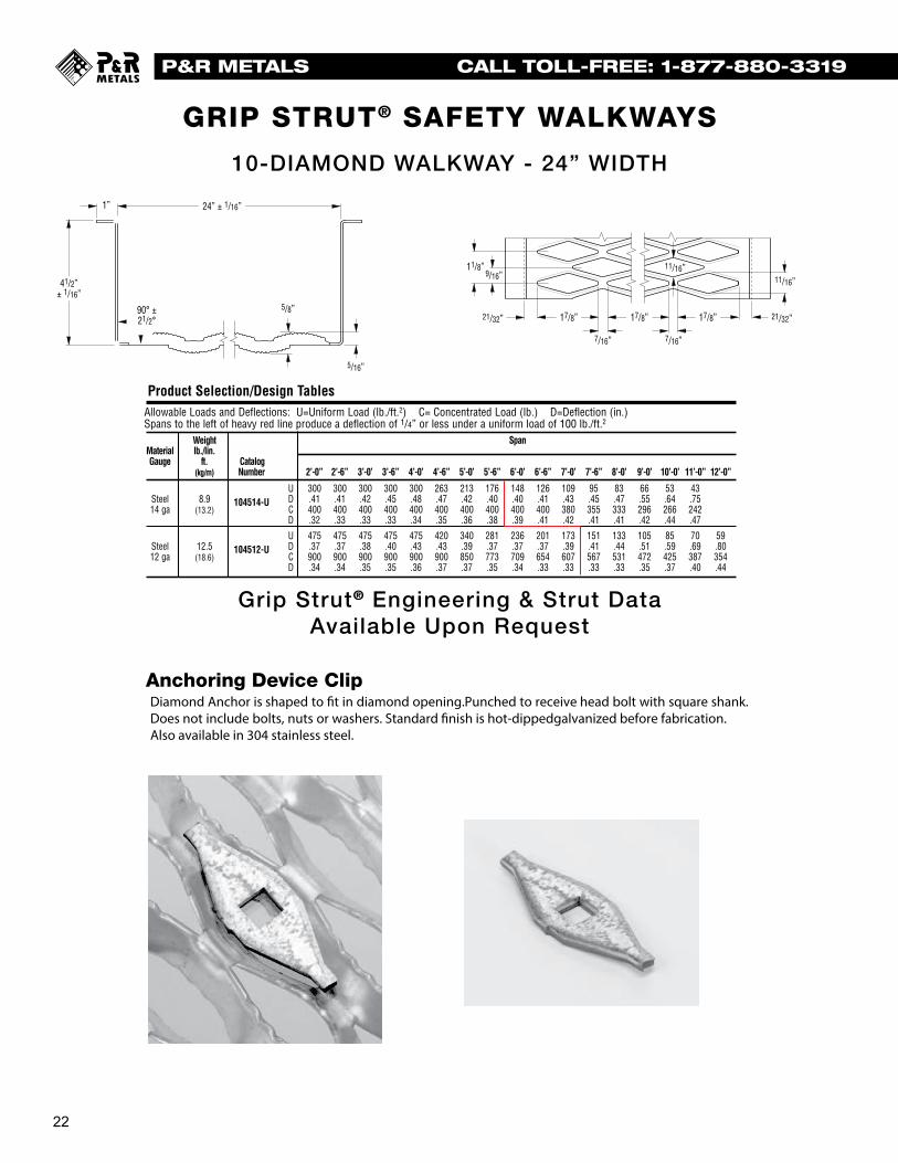
Anchoring Device Clip
LKWAYS
Grip Strut® Engineering & Strut Data Available Upon Request
25
Grip Strut® Safe Loading Tables10-Diamond Walkway __ 24” Width
Allowable Loads and Deflections: U=Uniform Load (lb./ft.2) C= Concentrated Load (lb.) D=Deflection (in.)Spans to the left of heavy red line produce a deflection of 1/4” or less under a uniform load of 100 lb./ft.2
Weight SpanMaterial lb./lin.Gauge ft. Catalog
(kg/m) Number 2’-0” 2’-6” 3’-0’ 3’-6” 4’-0’ 4’-6” 5’-0’ 5’-6” 6’-0’ 6’-6” 7’-0’ 7’-6” 8’-0’ 9’-0’ 10’-0’ 11’-0” 12’-0”
U 300 300 300 300 300 263 213 176 148 126 109 95 83 66 53 43Steel 8.9 104514-U D .41 .41 .42 .45 .48 .47 .42 .40 .40 .41 .43 .45 .47 .55 .64 .7514 ga (13.2) C 400 400 400 400 400 400 400 400 400 400 380 355 333 296 266 242
D .32 .33 .33 .33 .34 .35 .36 .38 .39 .41 .42 .41 .41 .42 .44 .47
U 475 475 475 475 475 420 340 281 236 201 173 151 133 105 85 70 59Steel 12.5 104512-U D .37 .37 .38 .40 .43 .43 .39 .37 .37 .37 .39 .41 .44 .51 .59 .69 .8012 ga (18.6) C 900 900 900 900 900 900 850 773 709 654 607 567 531 472 425 387 354
D .34 .34 .35 .35 .36 .37 .37 .35 .34 .33 .33 .33 .33 .35 .37 .40 .44
Product Selection/Design Tables
Engineering Data For Both Channels
ChannelMaterial Depth- Sx Ix E IGauge in. in.3 in.4 lb. x in.2
Steel 41/2” .806 1.43 41.47 x 10614 ga.
Steel 41/2” 1.290 2.42 10.03 x 10612 ga.
Strut LoadingMaterial Type DeflectionGauge Loading** Load in.
Steel U 300 .49
14 ga. Cs 300 .40
Steel U 475 .4512 ga. Cs 475 .36
** U = Allowable Uniform Load (lb./ft.2)Cs = Allowable Concentrated Load per ft. of length at mid-width (lb./ft.)
5/16”
5/8”90° ±21/2°
41/2”± 1/16”
1”
9/16”11/16”
11/16”
7/16” 7/16”
24” ± 1/16”
21/32” 21/32”
11/8”
17/8” 17/8” 17/8”
10-DIAMOND WALKWAY - 24” WIDTH
Diamond Anchor is shaped to in diamond opening.Punched to receive head bolt with square shank. Does not include bolts, nuts or washers. Standard �nish is hot-dippedgalvanized before fabrication. Also available in 304 stainless steel.

23
P&R METALS CALL TOLL-FREE: 1-877-880-3319
HEAVY-DUTY GRIP STRUT® SAFETY FLOORING
6
General Load Information
Heavy-Duty Grip Strut Planks — The Versatility of 91/4” to 36” Widths for Single- or Multi-WidthPlatforms, to Fit Every Job Requirement — And Many O.E.M.
Availability of Heavy-Duty Grip Strut Planks*
Walkway Width
Material Thickness 36” 273/4” 24” 133/4” 91/4”
11 ga.
Steel 10 ga.
9 ga.
Aluminum .125” -- -- --
* All in depths of 2”, 21/2”, 3” and 4”.
Universaldesigned(maximuminstallationtighteningBracketorderedfinish.to
ClipisPipe,mountedandlocated,inhothardwareHeavy-Duty
Heavy-Duty Grip Strut Safety Grating Planks are ideal for alltypes and sizes of platform applications with design loadrequirements beyond the capacities of regular Grip Strut SafetyGrating (fully described in Grip Strut Gratings and Stair Treadscatalog GSSGST-09). Four depths and five widths, each in steeland aluminum alloy 5052, provide versatility of load capacity forgreatest economy: adequate strength without over design. Eachwidth/side channel depth combination is available inmaterial/thickness combinations as shown above.
All can be used for single-plank applications, or in multi-plankcombinations for large-area platforms (see Multi-plank widthchart, opposite page). One combination of width/depth/metalthickness is certain to meet your requirements with exceptionaleconomy. For special job requirements, or the fine-tunedeconomies required by O.E.M. applications, other materials andmany special fabricating services are available from CooperB-Line (see page 22).
HandrailGripthoseWalkwayhandrailingrequiredsary
TheHandrailtion1910.23.
HEAVY-DUTY GRIP STRUT® PLANKSAVAILABLE IN LENGTHS UP TO 24’
General Load InformationHeavy-Duty GripStrut Walkways — The Safety Of OSHA-Required Toeboards, Built-In
Heavy-Duty Grip Strut Safety Grating Walkways, like Heavy-Duty Planks, offer additional strength for walkway applicationswith greater load requirements. Grating surface design isidentical. The walkway difference is in the side channels,which are turned up as 5 inch toeboards, exceeding OSHArequirements. Walkways offer all the slip-resistance andself-cleaning advantages of planks, and are available in the
Heavy-Duty Grip Strut Walkways incorporate 5 inch integraltoeboards, complying with OSHA regulations (appropriatesafety devices may also be necessary during use — consultapplicable safety regulations). Canadian compliant (OH&S)designs are also available in some sizes.
Handrail Brackets are available for application on Heavy-Duty
Availability of Heavy-Duty Grip Strut Walkways*
Walkway Width
Material Thickness 36” 30” 24”
11 ga.
Steel 10 ga.
9 ga.
Aluminum .125” --
* Standard toeboard depth of 5”.
specifications.construction.
public
local codeare
using
width
greater
drawings.
and shall
HEAVY-DUTY GRIP STRUT® WALKWAYSAVAILABLE IN LENGTHS UP TO 24’
Engineering & Load Data Provided Upon Request