precast concrete construction at forrestal village …
TRANSCRIPT

L/
Technical Memorandum M-069
PRECAST CONCRETE CONSTRUCTION AT FORRESTAL VILLAGE HOUSING PROJECT, GREAT LAKES, ILLINOIS
28 July 1952
:^§Si-N-%
u. s.
naval
civil
• * engineering
research
and
evaluation
laboratory
port hueneme,
California

U.S. Naval Civil Engineering Research and Evaluation Laboratory, Port Hueneme, California
Technical Memorandum M-069
PRECAST CONCRETE CONSTRUCTION AT FORRESTAL VILLAGE HOUSING PROJECT, GR*AT LAKES, ILLINOIS
28 July 1952
V'.R. Lorman and C.K. V'iehle
SOT-MARY
Forrestal Village, the Navy's 1000-family housing develop- ment at Great Lakes, Illinois, will consist, when completed about December 1952, of 31o single, duplex, and quadruplex structures. These buildings are of all-concrete construction: the ground floors are cast in place; the walls are made of precast concrete- cellular glass-concrete sandwich panels; and the roofs and second- story floors are made of hollow, precast concrete units. All connections between precast units are made by welding connectors embedded in the units at the time of casting. Assembly-line con- struction practices developed by the contractors have resulted in a speed of erection of 5 dwelling units a day at an over-all cost of about $8.00 a square foot.
Resistance of precast panels to deterioration might be im- proved if they were vacuum or high-pressure-steam cured and if air-entraining agents were incorporated in the mix. The use of fibrous glass in the sandwich panels might result in a thinner wall, and a more effective joint could be designed. Glass-fiber roofing would result in a lighter, more economical, and longer- lasting roof; and thinner wall panels could be effected by ver- tical pretensioning arid horizontal post-tensioning of the concrete shells comprising the sandwich construction.

FOREWORD
In August 1951 the Public Works Officer of the Ninth Naval District initiated negotiations with the U.S. Naval Civil Engineering Research and Evaluation Laboratory relative to the preparation of a technical paper covering the design and construction of Forrestal Village dwellings. Accordingly, the authors of this technical memorandum were detailed to visit the build- ing project in October 1951 at which time basic infor- mation was obtained at the site. Suitable arrangements were made at that time with the contractor and the staff of the Public Works Officer for subsequent tran3- raittal to the Laboratory of pertinent technical details required to complete the report properly. The purpose of this report is to serve as a technical record of the Forrestal-Viilage type of prefabricated housing.

TABLE CF CONTENTS page
INTRODUCTION . 1
STRUCTURAL MATERIALS 3
Concrete. . 3 Cellular Glass in Wall Panels . 6 Fibrous Glass as Insulation . 7 Paint 8
STRUCTURAL ASPECTS 9
FOUNDATION AND GROUND FLOOR 10
PRECAST SECTIONS 11
Walls 12 Flexicore Units 15 Erection of Precast Sections 17 Wall-Panel Joints . . . 20
HEATITG SYSTEM ........... 20
PRECAST CONSTRUCTION COSTS 21
CONCLUSIONS AND RECOMMENDATIONS 2^
Wall-Panel Concrete Materials . . 25 Wall-Panel Insulation Materials 25 Wall -Panel Joint Materials 25 Flat-Roof Materials . . . < 26 Wall-Panel Design 26
TABLES 27
ILLUSTRATIONS 35

TABLES page
1. Average Gradation of Aggregate for Ready-Mixed Concrete . , 27
2. Average Characteristics of Aggregate for Ready- Mixed Concrete ......... 2b
3. Average Mix Design for Ready-Mixed Concrete 29
h. Average Gradation of Aggregate for Flexicore Concrete 30
5. Average Characteristics of Aggregate for Flexicore Concrete . . . 31
6. Average Mix Design of Flexicore Concrete ...... 32
7. Ma^or Items of Construction Equipment Utilized at Forrestal Village 33
8. Physical Properties of Foamglas 3^
•

:.•['• A ,.,v:.;v__-^
^.--t::
i
ILLUSTRATIONS
figures page
1. Typical foundation-wall section and bearing wall . . 35
2. Method of forming outer tapering surface of the foundation wall . 3<$
3. Typical installation of heater plenum and heating ducts. ........... .... . . 3^
4. Finishing a concrete ground-floor slab . . 37
5. Wall-panel forms preparatory to concrete placement * 37
6. Installation of Foamglas in precast wall panels. . . 3S
7. Surface texture of wall-panel exterior face..... 38
8. Loading completed wall panel onto a semitrailer by means of vacuum pad 39
9. Removing wall panel from trailer preparatory to erection 39
10. Placement of l/2-inch-thick mortar bed upon foundation wall. . 40
11. Push-pull type tie rods used for shoring wall • panels prior to welding operations ... 40
12. Welding flat connectors to steel plates embedded in panels 4l
13. Typical plan of connection of sidewall to front or rear wall . ^_ 42
14. Typical connection of Flexicore floor slab to front or rear wall . . . 43
15• Typical connection of Flexicore roof slab to front or rear wall 44

gtf Iijfcyaywwifg .-. *%£ -,,.,_:i^-. . ,. ., :iamsii j&s»^ «* .*®i8S&*g#&fti^^
. .
ILLUSTRATIONS, Cont'd
figures page
16. Typical connection of Flexicore roof slab to side wall 45
17. Typical Flexicore roof or floor slab with grouted key joint 46
18. Positioning second-floor Flexicore units . . 47
19. Grouting joints between second-floor Flexicore units . . 47
20. Erection of wall panels at second-floor level of quadruplex structure 43
21. Use of embedded hooks during erection of side wall. . 43
22. Positioning of Flexicore fLat-roof units 49
23. Aerial view of partly completed quadruplex
24. Completed quadruplex structure, showing architectural treatment and appearance of wall-panel joints after calking ........ ..... ^0
25. Wood-frame hipped-roof surmounting the Flexicore ceiling slab in a single-story dwelling ....... 50
26. Eave detail of hipped-roof structure, showing rolled batt insulation packed into open ends of Flexicore units ............. 51
27. Typical duplex and quadruplex structures 51
28. Installation of partition walls in a typical dwelling unit . . .......... 52

:
INTRODUCTION
The Navy's current large-scale housing project, Forrestal Village, is being constructed on Federal property located about three miles southwest of the Great Lakes Naval Station, Illinois. This 1000-family housing development is provided for by Title VIII of the National Housing Act (8lst Congress), known as the Wherry Housing Bill. The project, covering approximately 162 acres (roughly six families per acre) and to cost an estimated nine million dollars, is expected to alleviate the critical housing problems confronting the families of enlisted and officer per- sonnel attached to the various naval activities at Great Lakes. The project is being built by private enterprise and will be operated by private enterprise until 1990, at which time owner- ship will be transferred to the Federal Government. The Federal Housing Administration, as authorized by the Wherry Bill, is permitted to insure the mortgage for not more than five million dollars. Standards of design, construction, and livability were set by the Navy and FHA; the contract was awarded on the basis of the best combination of dwelling livability, structural permanency, architectural attractiveness, and site development, rather than on the basis of lowest bid. However, the National Housing Act limits the maximum allowable cost of each dwelling unit (family unit) to 8100 dollars at this particular project.
The FHA is the interpreter of the general conditions, speci- fications, and drawings comprising the contract: decisions by the FHA, insofar as related to the terms of the contract, are final and binding. Moreover, the FHA has the authority to order work changes, particularly in cases involving safety of structure or personal life. Failure on the part of the FliA to detect imper- fections in work or materials does not serve as a waiver of the
* requirements or standards listed in the contract specifications.
Each unit consists of a combination living-dining room; a kitchen; a utility room; a bath; and either one, two, or three bedrooms. The smallest unit contains 7°0 square feet of floor space (gross) to rent for b9 dollars a month; the largest unit has 1615 square feet (gross) to rent for 110 dollars a month. The average floor space (net) per dwelling is about 970 square feet. The completed project will consist of 3l8 architectural- concrete buildings,involving ten individual types of dwellings. These buildings will contain 1000 dwelling units, 630 of which will be occupied by enlisted men's families and 320 by officers' families. There are three principal types of structures, irre- spective of bedrooms:

(1) k-family (quadruplex), 2-story, flat-roof;
(2) 2-family (duplex), 1-story, hip-roof; and
(3) 1-family (single), 1-story, hip-roof, with attached garage.
No community shopping, centers or related commercial features are to be included in the development. The project includes paved streets, sidevalks, driveways, playgrounds, landscaping, and all utilities. Each dwelling unit is provided with an electric water heater, an electric refrigerator, a gas cooking range, and a gas- fired heating apparatus.
After considering the qualifications of the 17 firms which had shown interest in the proposed project, the Public Works Officer of the Ninth Naval District selected six as being suffi- ciently qualified to act as sponsors of the development. These six firms were invited to submit specific proposals to finance, design, construct, operate, and maintain the project. Officials of the Ninth Naval District, the Bureau of Yards and Docks, and the FIIA gave final consideration to three of the submitted pro- posals; these were for wood frame, cement-asbestos board, and precast-concrete tilt-up construction. In June I950j the Secre- tary of the Navy selected the Corbetta Construction Company and the price Brothers Company, both of Chicago, as co-sponsors of the project. The co-spensors chose to collaborate with the architectural firm of Shaw, Iletz, and Dolio, of Chicago, which had previous experience in the design of largeTHA housing pro- jects, fir. A. Axirikian was retained as consulting engineer.
While awaiting the completion and approval of detailed design plans for tae concrete structures, the Navy let a con- tract for the demolition of the temporary buildings at the site (formerly a World War II military camp) to insure uninterrupted development of the housing project. Actual housing construction began in January 1951 and is expected to end in November 1952. As of October 1951 > 68 of the 1000 dwelling units had been com- pleted and were occupied. The construction schedule, after routine operations became firm, called for the completion of approxiraately five dwelling units a day. Because of adverse winter weather, operations were closed down for about three months.
The project distinctly demonstrates the adaptability of Portland-cement concrete to the field of housing, and should point the v. ay to future housing that utilizes "all-concrete" in the fullest sense of the terra. Floors are either cast in place or comprised of hollow precast units; exterior walls are

of the concrete-glass-concrete sandwich type; interior partitions J are constructed of either gypsnra board attached to studding or
cement-asbestos board incorporating a cane-fibre insulation core; • and the flat roofs of the quadruplex structures are made of hollow, precast concrete units.
The construction practices that Corbetta-Price have adopted are similar to the production-line technique employed in present- day industry; with slight modifications, the general design and construction procedures could become standard practice for the large-scale housing which undoubtedly will be needed to alleviate the nation housing problems now confronting us. Development of modular, precast, prestressed_ concrete panels would be a direct outgrowth of the development of such practices.
STRUCTURAL MATERIALS
The principal materials used in the construction of the development include concrete, cellular glass, fibrous glass, and paint.
Concrete
All concrete placed at the site is supplied by means of transit-mix trucks by the Lake County Ready-Mix Concrete Company, situated within short-hauling distance of the project. The total yardage of concrete (exclusive of Flexicore) to be placed for the entire project (including sidewalks, pavements, etc., in addition to the housing proper) is estimated as lj-0,000 cubic yards. Most
- mixes employ a type-I portland cement (Universal Portland Cement Company brand) but do not incorporate any air-entrcrtaifcg agents. Sources of natural sand are Crystal Lake, Illinois, and Algonquin, Illinois; and the gravel is from either Beloit, Wisconsin, or Crystal Lake, Illinois. Because of the comparatively high cost, no lightweight aggregates (pumice, expanded shale, or lightweight blast-furnace slag) are used in precast sections, nor is the use of them contemplated. Foundations, ground floors, and entrance platforms incorporate one-inch maximum aggregate; and pea gravel (3/8-inch maximum) is used in the various precast sections, such as wall panels, Flexicore units, stairs, and canopies.
Table 1 shows a typical gradation of the aggregate princi- pally employed at the project. The gradings conform to the requirements of the American Society for Testing Materials Speci- fication C33-^9 for concrete aggregates, but it is noted that the coarse aggregate incorporated in the precast wall panels more closely meets the requirements of ASTM Specification TJkk&-h9 (Aggregate Size 8) for highway construction than it does those of Specification C33-*l-9. The percentage of deleterious substances
r

shown in Table 2 are appreciably lower than are the percentages permitted by A5TM Specification 1M8-I+9, except for the fact that the coarse aggregate contains the maximum allowable percen- tage of Material finer than no. 200. The mix design character- istics of precast wall-panel concrete and concrete cast in situ are shown in Table 3. As only transit-mixed concrete is useTat the site, these mixes conform generally to ASTM Specification C9U-I+8 for ready-mixed concrete.
Two standard 6- by 12-inch test cylinders are cast for each mix for each day's placing schedule. When the ultimate 28-day compressive strength of any cylinder falls below the minimum strength specified for the class of concrete tested, the mix proportions, the water-cement ratio, or the curing conditions are altered to insure that the required compressive strength is obtained. To expedite any necessary batching changes, pro- portional 7-day strength tests are resorted to.
The placing of all concrete in situ and of all concrete comprising units fabricated in the casting yard is accomplished with the aid of internal vibrating equipment. Specifications prohibit form vibration.
All laboratory and field tests of concrete (except Flexicore) are made by the Robert W. Hunt Company, Chicago, Illinois, for Corbetta-Price in accordance with ASTM standards. The ASTM stan- dards referred to in the specifications covering the fabrication and testing of concrete specimens are for the year 1939* Test results are submitted weekly to the FHA for review. It was _the authors' understanding that inspection was a serious problem because of a shortage of personnel assigned to that task; this
I problem was especially serious with regard to the casting-yard I operations. .,_ ....
1. It appears that much closer control and earlier establish- ment of adequate compressive strength could be obtained by using accelerated (steam) curing of specimens and by testing them at
I age 8 hours. Strength results thus obtained could be employed to predict the 28-day strengths, after the average strength ratio (28-day : 8-hour) had been determined for the materials peculiar to this project.
2. However, it appears that more thorough and consistent com- paction could be attained through the use of vibrating screed equipment when casting wall panels, stairs, canopies, etc. The use of such equipment would minimize or, perhaps, eliminate blemishes ordinarily considered unavoidable, and the resulting smooth and dense surfaces would be truly architectural concrete.
r.-^Zl*-,'.^.-
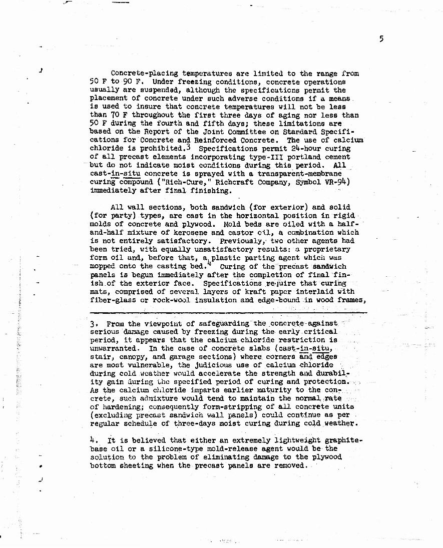
Concrete-placing temperatures are limited to the range from 50 F to 90 F. Under freezing conditions, concrete operations usually are suspended, although the specifications permit the placement of concrete under such adverse conditions if a means is used to insure that concrete temperatures will not be less than 70 F throughout the first three days of aging nor less than 50 F during the fourth and fifth days; these limitations are "based on the Report of the Joint Committee on Standard Specifi- cations for Concrete and Reinforced Concrete. The use of calcium chloride is prohibited.3 Specifications permit 24-hour curing of all precast elements incorporating type-Ill portland cement but do not indicate moist conditions during this period. All cast-in-situ concrete is sprayed with a transparent-membrane curing compound ("Rich-Cure," Richcraft Company, Symbol VR-9*0 immediately after final finishing.
Ail wall sections, both sandwich (for exterior) and solid (for party) types, are cast in the horizontal position in rigid molds of concrete and plywood. Mold beds are oiled with a half- and-half mixture of kerosene and castor oil, a combination which is not entirely satisfactory. Previously, two other agents had been tried, with equally unsatisfactory results: a proprietary form oil and, before that, a plastic parting agent which was mopped onto the casting bed. Curing of the precast sandwich panels is begun immediately after the completion of final fin- ish of the exterior face. Specifications require that curing mats, comprised of several layers of kraft paper interlaid with
I fiber-glass or rock-wool insulation and edge-bound in wood frames, 1 .— I I II . . 1 II I -I -I -,..,,
3. From the viewpoint of safeguarding the concrete against '" I serious damage caused by freezing during the early critical
period, it appears that the calcium ehlori.de restriction is unwarranted. In the case of concrete slabs (cast-in-situ, stair, canopy, and garage sections) where corners and edges are most vulnerable, the judicious use of calcium chloride during cold weather would accelerate the strength and durabil- ity gain during the specified period of curing and protection. . :. As the calcium chloride imparts earlier maturity to the con- crete, such admixture would tend to maintain the normal rate of hardening; consequently form-stripping of all concrete units (excluding precast sandwich wall panels) could continue as per regular schedule of three-days moist curing during cold weather.
k. It is believed that either an extremely lightweight graphite- base oil or a silicone-type mold-release agent would be the solution to the problem of eliminating damage to the plywood
0 bottom sheeting when the precast panels are removed.
1

be laid over the entire casting bed and allowed to remain in position (undisturbed) for not less than 60 hours. These mats not only aid in the curing process but also protect the precast wall sections against excessively hot or freezing ambient con- ditions. As a rule, precast walls receive approximately 72 hours of moist curing but are covered with insulated curing mats only during cold weather, although the specifications require that mats must be used at all times. Cast walls are removed from the mold bed not sooner than the fourth morning after the casting day.
Cellular Glass in Wall Panels
The first North American structure incorporating wall panels comprised of a concrete sandwich with a cellular glass core was an industrial warehouse erected in 19^7 In Canada. Forrestal Village is the first residential housing project to employ con- crete-glass sandwich construction. Foamglas, which is used at Forrestal Village, is a rigid block that is inorganic and vesic- ular; the closed-cell character of the material is the result of innumerable glass bubbles forming a continuous structure, which is odorless, vermin-proof, and noncombustible.
THERMAL CONDUCTIVITY. As far as known, no tests have been - conducted to determine the thermal conductivity of the concrete- glass sandwich panels. As the coefficients of transmission of the component parts of the wall panel are known for the most part, designers were satisfied to use calculated U values. Al- though such calculations do not account for the effect of joints^ or for metal extending from face to face of the panel, the U values so computed were considered sufficiently accurate for most purposes. An over-all coefficient of heat transmission (u) value of O.198 Btu hr_1ft-2deg F~lin. was computed and used for the wall panels at Forrestal Village. This figure is conservative, as it is based on a thermal conductivity (k) value of 12 for concrete and 0A0 for Foamglas at a mean temperature of 50 F. In computing U, a thermal resistance value of 0.17 for the exterior surface of the external concrete shell was based on an assumed cold-side film- transmittance coefficient (fQ) of 6.0 (corresponding to a 15-mph wind condition), and a resistance value of 0.6l for the interior face of the internal concrete shell (assuming still air) was based on an average warm-side film-transmittance coefficient (f±) of I.65.
5. No insulation barrier exists throughout areas immediately adjacent to wall construction joints (vertical or horizontal); and, for this reason, condensation on the interior surfaces of the sandwich walls would be likely under severe^climatic condi- tions, as in the case where outdoor temperature is OF while room temperature is 70 F at 60 per cent relative humidity.

5
FIRE RESISTANCE. A fire resistance test of a 6-inoh-thick concrete-Foamglas sandwich panel was conducted at the National Bureau of Standards in February 1950. A fire-resistance rating of four hours was assigned to this particular assembly; all re- quirements of the hose-stream test were fulfilled by the test panel after six hours of fire exposure where the maximum tempera- ture was about 2250 F. As far as known, no other fire-endurance investigations of this type of sandwich construction have been made.
WATER-VAPOR TRANSMISSION. No water-vapor transmission tests of concrete-glas3-concrete sandwich wall panels have been made, as far as can be ascertained. Because of its vesicular nature, Foamglas should possess high resistance to moisture and water vapor. In a sandwich wall panel, such as used in Forrestal Village construction, the cellular glass serves to stop or, at least, to minimize, water-vapor migration from one surface of the wall to the other side. However, water vapor may be trans- mitted through the Foamglas Joints unless an effective mastic joint sealer is used; no such sealers were installed in the sand- wich panels erected at Forrestal Village. Similarly, no water- vapor barrier in the form of Foamglas exists in the areas im- mediately adjacent to the wall-panel joints.
STRUCTURAL PROPERTIES WHEN COMBINED WITH CONCRETE. As far as known, no investigation has been made concerning racking-load capacity of a typical concrete-glass-concrete sandwich wall panel. The flexure and shear properties of such panels were investigated in 19^8 by L'Ecole Polytechnique at Montreal, which activity also performed pull-out tests for bond of a metal anchored in the panel. However, the results of these Canadian investigations were not available at the time this report was written.
- OTHER PHYSICAL PROPERTIES. Foamglas is manufactured in block form (12 by 13 inches is standard) and is available in various thicknesses, ranging from 2 inches to 5 inches. Dimen- sional tolerance for blocks of all sizes is about l/l6 inch. Various physical properties of interest are shown in Table 8. It will be noted that the coefficient of expansion of Foamglas is k x 10~" in/in/degree F which is about one-third less than that of average portland cement concrete.
Fibrous Glass as Insulation.
At Forrestal Village, all foundation-perimeter insulation and all flat-roof insulation is comprised of l-l/2-inch-thick, standard-size (2 by k feet) Fiberglas units. The core of this insu- lation material ie composed of inorganic, resilient glass fibers securely bonded together with a thermosetting resin. One 2- by 4-foot face is coated with asphalt. Kraft paper is then firmly affixed to the

8
asphalt and bound over both ends of the unit. The purpose of the paper is to provide a good mopping surface, especially when such preformed units are employed as flat-roof insulation com- ponents. Pertinent details of application are given on pages 10 and 19.
THERMAL CONDUCTIVITY. The nominal coefficient of heat con- ductance (c) of l-l/2-inch-thick Fiberglas preformed insulation is 0.17 Btu hr-ift^deg F"1^.
FIRE RESISTANCE. Preformed Fiberglas is incombustible, but the presence of the thermosetting binder limits the use of the material to a maximum temperature of 450 F. No technical data appear to be available concerning standard fire-resistance tests comparable to those made in connection with Foamglas.
WATER-VAPOR TRANSMISSION. As Fiberglas has a fibrous struc- ture and thus is not a cellular material such as Foamglas, water can enter the interstices but is not absorbed by the fibers. In very humid atmospheres, the adsorption supposedly is not greater than one per cent by weight. Although no substantiating tost data are available, it is reasonable to presume that, should the Fiberglas become wet, it would dry with proper drainage and aeration. _:_
OTHER PHYSICAL PROPERTIES. Fiberglas preformed units are commercially available in densities ranging from 2.0 to 10.5 lb per cu ft and in thicknesses ranging from 1.5 to. 5.0 inches. The modulus of rupture of the material with a density of 9»0 lb per cu ft is about 45 psi, and the ability of one-inch-thick material to resist delamination averages slightly above 1 psi. At a maximum compressive stress of 330 psf, the one-inch-thick board undergoes a total deformation of about 0.1 inch; and, upon removal of load, recovery is about 99 per cent.
Paint
All exterior concrete is covered with one coat of exterior resin-emulsion masonry paint. No exterior painting is allowed during rainy weather or when the ambient temperature is below 50 F, Interior concrete walls and ceilings, as well as cement- asbestos board partitions, are covered with one coat of resin- emulsion paint fortified with 25-per cent latex. The resin- emulsion paints used in these applications conform to Federal Specification TT-P-88a. All paint, exterior and interior, is applied by brush.
-
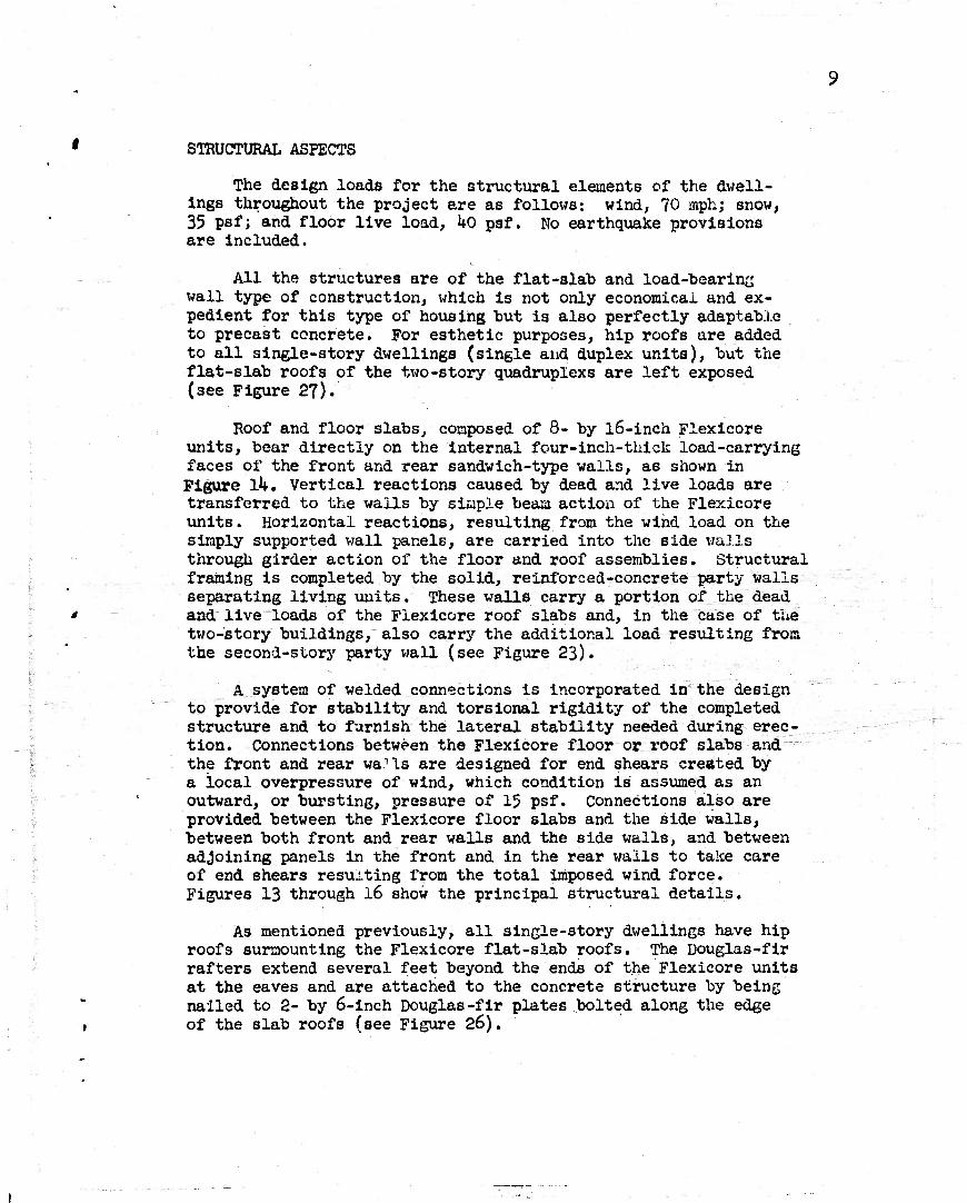
STRUCTURAL ASPECTS
The design loads for the structural elements of the dwell- ings throughout the project are as follows: wind, 70 mph; snow, 35 psf; and floor live load, kO psf. No earthquake provisions are included.
All the strtxctures are of the flat-slab and load-bearing wall type of construction, which is not only economical and ex- pedient for this type of housing but is also perfectly adaptable to precast concrete. For esthetic purposes, hip roofs are added to all single-story dwellings (single and duplex units), but the flat-slab roofs of the two-story quadruplexs are left exposed (3ee Figure 27).
Roof and floor slabs, composed of 8- by l6-inch Flexicore units, bear directly on the internal four-inch-thick load-carrying faces of the front and rear sandwich-type walls, a6 shown in Figure lU. Vertical reactions caused by dead and live loads are transferred to the walls by simple beam action of the Flexicore units. Horizontal reactions, resulting from the wind load on the simply supported wall panels, are carried into the side walls through girder action of the floor and roof assemblies. Structural framing is completed by the solid, reinforced-concrete party walls separating living units. These walls carry a portion of the dead and live loads of the Flexicore roof slabs and, in the case of the two-story buildings, also carry the additional load resulting from the second-story party wall (see Figure 23).
A system of welded connections is incorporated in the design to provide for stability and torsional rigidity of the completed structure and to furnish the lateral stability needed during erec- tion. Connections between the Flexicore floor or roof-slabs and the front and rear wa^ls are designed for end shears created by a local overpressure of wind, which condition is assumed as an outward, or bursting, pressure of 15 psf. Connections also are provided between the Flexicore floor slabs and the side walls, between both front and rear walls and the side walls, and between adjoining panels in the front and in the rear walls to take care of end shears resulting from the total imposed wind force. Figures 13 through 16 show the principal structural details.
As mentioned previously, all single-story dwellings have hip roofs surmounting the Flexicore flat-slab roofs. The Douglas-fir rafters extend several feet beyond the ends of the Flexicore units at the eaves and are attached to the concrete structure by being nailed to 2- by 6-inch Douglas-fir plates bolted along the edge of the slab roofs (see Figure 26).

10
The structural design does not provide for resistance to lateral forces between the precast wall panels and the founda- tion, as earthquakes are not considered critical in the Great Lakes area. The typical joint between the wall panels and the foundation is made by spreading a l/2-inch-thick layer of port- land-cement mortar on top of the foundation wall immediately prior to the erection of the wall section; erection details are described on page 18 (see, also, Figures 10 and 20).
Forces resulting from the dead and live loads of the super- structure are transmitted to the earth by a continuous wall-type foundation. To distribute the loads adequately at slues where the allowable soil pressures (which range from 1700 to 2700 psf) are exceeded, the foundation wall is placed on a one-foot-thick by two-foot-wide pedestal, or footing, poured monolithically with the foundation. Because of frost penetrations, the founda- tion wall must extend a minimum of three feet below the surface of the ground; in addition, the foundation must be placed on solid and undisturbed earth. In an effort to distribute properly the soil reaction caused by the party-wall loads, a two-foot- square pier, extending the full depth of the foundation wall, is placed under the ends of the party walls; in addition, the ground- floor concrete slab under the party wall is thickened a minimum of 8 inches to extend it onto undisturbed soil of good bearing value. The foundation is of plain, concrete construction, contains no reinforcing nor temperature steel, and incorporates no contrac- tion joints.
FOUNDATIONS AND GROUND FLOORS
The foundation walls, entrance platforms, and ground-floor slabs are the only cast-in-place concrete members of the duelling structures. Foundation walls extend a minimum of 3 feet below grade and taper from an 8-inch width at the top to a l6-inch width at the base. All foundations are placed on solid and un- disturbed earth; Figures 1, 2, and 10 indicate tjfpical construc- tion details. A If-inch-thick monolithic concrete slab (steel- troweled) forms the ground floor of all dwelling units. Designed for a live load of hO psf, the slab is reinforced with 6- by 6-inch, no. 10/no. 10 welded wire mesh conforming to ASTM Speci- fication A82-34 and weighing 20 lb per 100 sq ft. The mesh is placed in well-lapped layers a minimum of 3A inch above the slab bottom. As in the foundation, normal portland-cement concrete is used. Underlying the slab is a thoroughly tamped, layer of clean, screened, porous gravel not less than h inches deep, to act as a sub-base. Between this gravel fill and the slab, a heavy, waterproofed, and reinforced kraft paper (Siss1kraft) is placed to provide a membrane for damp proofing ana to con- tain the gravel during concreting operations, A l/2-inch-

11
thick vertical layer of Fiberglas insulation, extending 18 inches below the floor line, serves to insulate the slab edges from the adjoining foundation wall.
Construction begins by excavating for the three-foot-deep foundation walls and the sewer-line connections with a Barber- Greene trencher. Prefabricated wood panels are fixed in position to form the outer, sloping surface of the wall, and rigid Fiber- glas insulation is nailed to 2- by 6-inch studs to form the inner portion of the wall that extends above the grade. Wherever practi- cal, the inside face of the earth trench cut below grade is used as a form for the inner face of the wall. Transit-mix trucks _ delivery ready-mixed concrete directly to the forms. Figure 2 shows a*general view of this construction. Wood blocks, set in the concrete before it hardens, act as spacers and as nailing blocks for the forms used later in casting the floor slab. Rough plumbing, which has been assembled by a subcontractor, is posi- tioned prior to the placing of the well-compacted, h-inch layer of porous-gravel fill. After the membrane damp-proofing is in- stalled over the gravel, the precast-concrete heater plenum and the tile heating ducts (vitrified clay pipe) for supplying heat to the ground-floor area are placed (see Figure 3)> and the con- crete floor slab is poured (see Figure k). If filling is neces- sary under the foundations, it is done with approved concrete, as directed; earth filling under foundations is not acceptable. The original plan called for the forming of the forced-air heat ducts by the use of air-expanded rubber tubes placed in the slab;
"f_ _.__ this method was discontinued, however, and replaced with the method involving clay-pipe ducts. After the curing of the floor slab is accomplished, as described on page 5 > the formwork is removed; the foundation structure is then ready to receive the precast wall sections. Back-filling against the foundations is done wherever necessary as soon as the concrete can withstand the weight of earth. Construction schedule of the foundations at the site is co-ordinated with the production schedule of the precast elements to insure uninterrupted erection of the build- ings; an average of two building foundations are laid a day.
PRECAST SECTIONS
Exterior walls, party walls separating family units in duplex and quadruplex structures, stairways, canopies, second floors, and flat roofs are of precast-concrete construction. The main framing assembly of each family unit is composed of 6-inch-thick, solid, reinforced-concrete party walls; precast concrete-sandwich wail panels; and 8-inch-deep second-floor and flat-roof Flexicore slabs. Suitable steel cast into the
» various precast elements serve to interconnect the various com- ponents, all connections being welded. Partition walls in

12
individual dwelling units are comprised either of gypsum boards mounted on 2- by 4-inch wood studs or of cement-asbe6tos (Cemesto) boards with a vegetable-fibre (Celotex) inner core, the total thickness being two inches. Partitions are installed by attaching them to wood plates bolted to the concrete floor and to the ceil- ing; the joints thus created are covered with suitable baseboards and molding trim. Figure 28 indicates this particular construc- tion. All steel reinforcing bars conform to the requirements of ASTM Specifications S15-39 and A16-39.
Walls
At the site, the foundation walls, rough plumbing, heat ducts, etc., and the placement of the concrete ground-floor slab are ac- complished preparatory to the installation of the precast wall sections. Originally, wall sections were cast at the site, the concrete floor slabs being used as casting beds, and were tilted up into final position; this method, however, was soon discontin- ued because of the impracticability of fulfilling necessary toler- ances in the concrete floor-slab surface. Simultaneously with foundation and ground-floor construction operations, other crews are engaged in casting various wall sections, complete with win- dow and door frames; this fabrication involves such details as attaching connector angles, inserting anchors for lifting purposes, placing electric-wire runways, etc. The panels are cast in forms laid out as eight casting beds, each of which is 10 feet wide by 300 feet long. AH walls for the largest building in this project can be cast in one bed. Casting beds consist of monolithic con- crete slabs in which 2- by 4-inch wood sections have been embedded; plastic-coated plywood, nailed to the 2 by 4*s, provides a smooth finish to the inner surface of the concrete wall which is cast upon it. The front and rear walls of one-story buildings (single units or duplexes) are cast in three or four sections, the number
2 depending upon floor area and type; the side walls are cast in one ? piece.
Exterior walls are composed of an outer reinforced-concrete shell 2-1/2 inches thick, a layer of cellular glass (Foemglas)
i 1-1/2 inches thick, and en inner reinforced-concrete shell k inches thick. The inner and outer shells are tied together with extruded- type metal lath. The Foamglas sandwiched between the shells serves as a vapor and moisture barrier (see pages 6 and 7) and also as thermal insulation; thus it tends to insure dry walls. Casting- yard operations are planned well in advance; each day's operation conforms to a definite fabrication schedule compatible with erection requirements at the various building sites.
WALL-PANEL CASTING. Edge forms for wall-panel casting are set, the entire form is cleaned, and the form oil is applied to the plywood facing and the edge-form interiors. All steel window
13
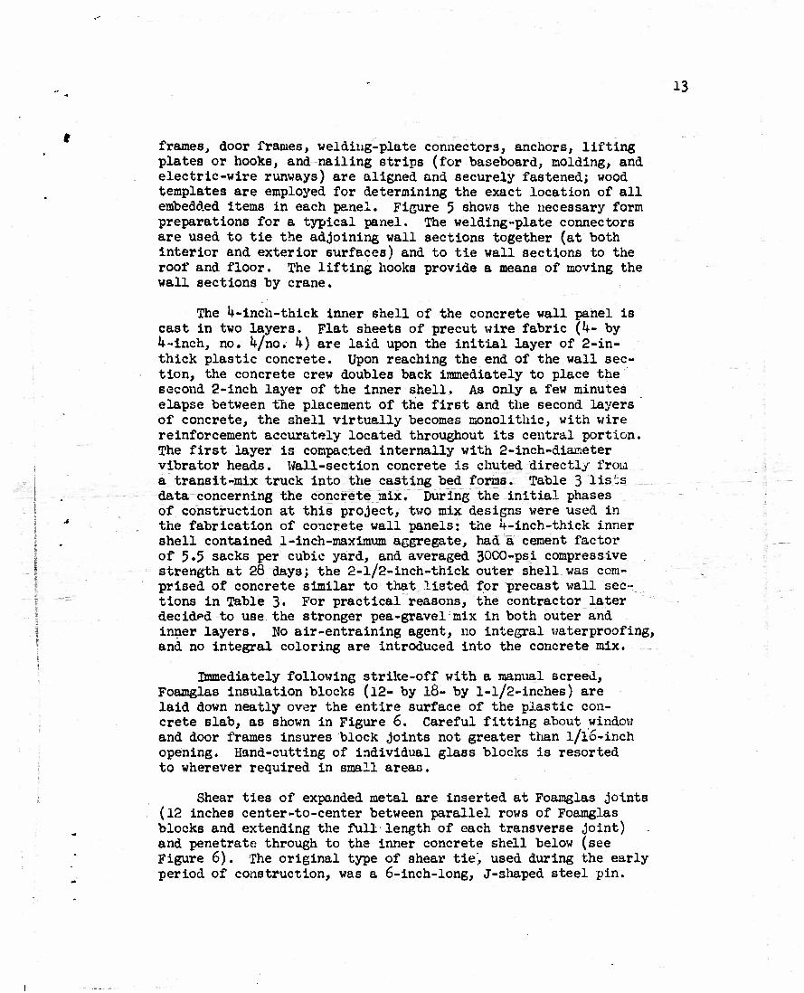
frames, door frames, welding-plate connectors, anchors, lifting plates or hooks, and nailing strips (for baseboard, molding, and electric-wire runways) are aligned and securely fastened; wood templates are employed for determining the exact location of all embedded items in each panel. Figure 5 shows the necessary form preparations for a typical panel. The welding-plate connectors are used to tie the adjoining wall sections together (at both interior and exterior surfaces) and to tie wall sections to the roof and floor. The lifting hooks provide a means of moving the wall sections by crane.
The 4-inch-thick inner shell of the concrete wall panel is cast in two layers. Flat sheets of precut wire fabric (4- by 4-inch, no. 4/no.- k) are laid upon the initial layer of 2-in- thick plastic concrete. Upon reaching the end of the wall sec- tion, the concrete crew doubles back immediately to place the second 2-inch layer of the inner shell. As only a few minutes elapse between the placement of the first and the second layers of concrete, the shell virtually becomes monolithic, with wire reinforcement accurately located throughout its central portion. The first layer is compacted internally with 2-inch-diameter vibrator heads. Wall-section concrete is chuted directly from a transit-mix truck into the casting bed forms. Table 3 lis'^s data concerning the concrete mix. During the initial phases of construction at this project, two mix designs were used in the fabrication of concrete wall panels: the 4-inch-thick inner shell contained 1-inch-maximum aggregate, had a cement factor of 5*5 sacks per cubic yard, and averaged 30C0-psi compressive strength at 28 days; the 2-l/2-inch-thick outer shell was com- prised of concrete similar to that listed for precast wall sec- tions in Table 3« For practical reasons, the contractor later decided to use the stronger pea-gravel mix in both outer and inner layers. No air-entraining agent, no integral waterproofing, and no integral coloring are introduced into the concrete mix. __.
Immediately following strike-off with a manual screed, Foamglas insulation blocks (12- by 18- by l-l/2-inches) are laid down neatly over the entire surface of the plastic con- crete slab, as shown in Figure 6. Careful fitting about window and door frames insures block joints not greater than l/l6-inch opening. Hand-cutting of individual glass blocks is resorted to wherever required in small areas.
Shear ties of expanded metal are inserted at Foamglas joints (12 inches center-to-center between parallel rows of Foamglas blocks and extending the full length of each transverse joint) and penetrate through to the inner concrete shell below (see Figure 6). The original type of shear tie, used during the early period of construction, was a 6-inch-long, j-shaped steel pin.
i ->

Ik
These pins were installed manually by punching them down through the Foamglas, filling the resultant hole in the Foamglas with grout, and reinserting the pin; one pin for each 12- by l8-inch glass block was employed on the average. The J-pin method was superseded by a method involving the use of ^-inch-wide strips of k- by U-inch no. 9/no. 9 welded wire mesh; this second method was later replaced by the expanded-metal shear-tie method des- cribed above.
Wire mesh (2- by 2-inch, no. 10/no/lO) is laid upon the glass insulation and is wire-secured to the shear ties, which serve as anchors for the mesh and also as spacer devices, corners of the window and door frames are reinforced with an extra layer of wire fabric of the same size, which is fastened to the primary rein- forcement; this added precaution was introduced during the early stages of the project after severe cracking had been encountered in the erected wall sections at re-entrant angles formed by open- ings such as doors and windows.
The final, or outer, concrete shell (2-1/2 inches thick) is placed and the surface is appropriately steel-troweled, grooved, and broomed to give a pleasing appearance. Architectural-embossed treatment (see Figure 7) is accomplished by indenturing a relief mold into "the fresh concrete. The upper, or exposed, face of the panel serves as the outer shell of the erected wall.
After the panels are erected, as described on page 18, those interior surfaces which are exposed to view are rubbed down with water and suitable hand stones in order to remove fins and minor imperfections. Honeycombed areas are removed entirely, and the resulting cavities are replaced with suitable neat-pcrtland-cement patches surface-finished to simulate the texture of the adjacent concrete.
During the summer months when atmospheric temperatures at Great Lakes are rather high, wall panels are moist-cured approxi- mately 2-1/2 days under wet burlap; throughout the remainder of the year, wall panels are cured through the use of rock wool enclosed in waterproof kraft paper (Sisalkraft), which is edge- bound in wood frames for portability. This departure from speci- fication requirements has been discussed on page 5.
WALL-PANEL MOVING. After the curing of the panels is complete, the slip-type edge forms are loosened and moved outward, away from the wall sections; any bond existing between the wall inner face and plywood form panel and between the interior edge forms and the panel is broken by applying a hydraulic wedge (Blackhawk). Each section is removed from the casting bed by means of a vacuum lift- ing pad, with a lifting capacity of 15 tons, attached to a crane

15
».with a capacity of 20 tons. Sponge-rubber strips cemented to the face of the vacuum pad provide a seal between the pad and the surface of the wall section. A vacuum pump, mounted on the rear of the crane cab, provides the partial vacuum. The weight
• of the largest single wall panel lifted is about 10 tons. The lifting crew is comprised of a foreman, a crane operator, and four riggers. The riggers loosen the forms, position the vacuum pad, and secure the wall panels after they have been lifted onto , the specially equipped truck trailers which are continually in.
• use delivering panels to the building sites. Two panels are swung onto each semitrailer and are placed vertically against timber A-frames built upon the trailer bed. The A-frames are. covered with rubber at locations where abrasion is likely to occur; two special clamps placed over the upper edges of the
- standing wall sections secure the precast sections to the A-frame. Figure 8 shows a wall section being lowered into position on a semitrailer.
Wall panels are hauled directly to location in the proper sequence for erection. Building sites are situated within a quarter-mile radius of the casting yard. Front, rear, and side walls are erected in the order named. All panels are removed from the semitrailers by a crane with a lifting capacity of 30 tons, equipped with a special lifting rig. The rig is com- prised of two hooks attached to a horizontal steel beam suspended by the crane; the hooks engage loops which had been embedded in the top edges of each panel during casting operations (see Fig- ures 9 and 21).
Flexicore Units
Each Flexicore precast-concrete unit (beam) used at this _, project is 16 inches wide by 8 inches deep and is lightened by two longitudinal holes 6-1/8 inch in diameter, steel reinforce- ment (l<O,000-psi yield point) consists of three rods ( a 1/2- inch round at bottom center and a 5/8-inch round at each bottom corner) in the lower portion of the beam and two compression rods (l/2-ihch round) in the upper portion; the latter is also useful in handling the units. Minimum concrete coverage over the rein-
• forcing steel is 3 A inch/which meets most building-code require- ments for a two-hour fire rating. Suitable stirrups are tack- welded to the top rods. A cross-sectional view of Flexicore units is shown in Figure 17.
Flexicore beams, as originally designed and fabricated by the Price Brothers Company, has a cross-section 6 inches deep by . 12 inches wide and a maximum permissible span of 22-1/2 feet. To meet the longer span and greater load requirements of this hous- ing project, it became necessary to redesign the Flexicore unit;

16
this redesign resulted in the 8- by l6-lnch cross-sectional di- mensions. The maximum clear span at Porrestal Village is approxi- mately 25 feet; including overhang, the longest Flexicore units are slightly under 28 feet in length. Design is based on the "Building Regulations for Reinforced Concrete,"(American Concrete Institute Standard 318-^1), supplemented by "Minimum Standard Requirements for Precast Concrete Floor Units," (ACI 711-46), and indicates an ultimate unit compressive stress in the concrete, (f*c) of 3750 psi and a tensile unit stress in the longitudinal steel reinforcement of 20,000 psi.
c There are ample test data available from reliable sources
covering load, deflection, shear, and recovery characteristics of Flexicore units, both the 6- by 12-inch and 8- by l6-inch sizes, tested as simple beams. The tests indicate that less deflection, less tensile cracking, and greater ultimate strength may be expected with these units than with ordinary reinforced- concrete beams containing an equal amount of steel in an equiva- lent cross-sectional area. The most recently available Flexicore simple-beam test results deal with 8- by l6-inch units having clear spans of 2k and 26 feet. These experiments were conducted at the Price Brothers Company plant at Dayton under the direction of Professor George E. Large, of Ohio State University. In these tests, visible hairline cracks occurred, at loads that were ap- proximately one-fourth greater than the total of dead load plus design live load. Recovery of the Flexicore units, after a 24-hour, sustained, constant load application, was well within the 75-per cent deflection recovery specified in the "Building Regulations for Reinforced Concrete" (ACI 318-^1).
Although there are plentiful test data concerning floor slabs comprised of 6- by 12-inch Flexicore units, no test data presently are available that reveal detailed performance of a slab comprised of 8- by l6-inch Flexicore units. Tests made in I9A3 at the Mid-West Concrete Pipe Company, Franklin Park, Illin- ois, to determine the adequacy of the grouted key joints of a 6-inch-deel slab comprised of five Flexicore units, show that the joints successfully transferred the load from the center unit to the outer edges of the slab. Figure 17 discloses details of a typical keyed joint. In view of the results of the Mid-West Concrete pipe Company's tests, not to mention many other satis- factory tests of slabs incorporating 6- by 12-inch Flexicore units, it is safe to assume that slabs comprised of the larger
'i • ' • . •• ' 111 11 • • • 1 • m
0. G.E. Large, "Report of Tests Made Upon •Flexicore' Floor Slabs for the City of Philadelphia, Pa.," 6 March 1951 and F. A. Randall letter report of 9 October 19^5 to the Chicago Building Commission describing results of Flexicore tests made at the Ohio State Uni- versity in 1942 and 19*4-3 and at the University of Wisconsin in 19^i»

17
Flexicore units will perform as expected and will distribute loads from the central portions to the outer edges as well as do the Blahs composed of the smaller units.
In the manufacture of Flexicore units, the bottom rods are tensioned to about 20,000 psi7 by tightening the nuts, which are screwed over threaded studs welded to reinforcing-rod ends, against the end of the steel mold by means of a pneumatic torque wrench. In the design of these units, the moments and shears are computed by the usual procedure and are not determined by using any theory of prestressed concrete. This method of stress- ing the bottom steel reinforcement in Flexicore fabrication also serves as a means of holding the steel in proper position during concrete placement and prior to the hardening of the concrete; moreover, this stressing results in less deflection, greater ultimate strength, and lesser amounts of cracking in the rein- forced-concrete unit than would ordinarily be the case.
FLEXICORE CASTING. Flexicore precast-concrete sections are fabricated under comparatively rigiC control. The mix de- sign and physical characteristics of Flexicore concrete are found in Tables k, 5* and 6. Compressive-strength values of test cylinders usually exceed kOQO psi. FKA specifications require a compressive strength of 3750 psi at age 23 days with
l_ ' a 2-inch slump and cement content of 6.5 sacks per cubic yard; the average strength of Flexicore concrete at 26 days is kkJO psi, and it is commonplace to have 3100-psi concrete at age 7 days as a result of atmospheric steam curing. All batching and mix control is accomplished in the Flexicore plant, operated by the Price Brothers Company, which is located about five miles from the project. The maximum size of the aggregate is 3/8 inch. All aggregates are from Crystal Lake, Illinois, one of the sources of materials employed in the ready-mixed concrete delivered to the project. The concrete comprising Flexicore units is vibrated in the molds on a vibrating platform and is screeded by hand (not troweled) prior to placement in the steam-curing chamber. The longitudinal holes are formed by means of special rubber hoses inflated to the correct diameter; after about three hours of a total of 2k hours of steam curing (atmospheric with water vapor at 150 F), the hoses are deflated and removed.
['. FLEXICORE M0VUIG. Precast units are transported from the \ Flexicore casting plant to the site by motorized straddle-type
carriers in quantities (about 30 units per load) consistent with erection progress.
7. It is probable that any benefits of such prestressing of mild steel may be reduced by creep and shrinkage of the Flexicore concrete.
f The use of an extremely high-strength cold-drawn wire or wire rope \ (at least 200,000-psi yield point) would be more compatible with the
commonly-accepted interpretation of the term "prestressed concrete."

18
Erection of Precast Sections
Rigid connections between adjoining precast sections are effected by welding flat connectors which were embedded in the sections at the time of casting (see Figure 12). In order to connect the contiguous members satisfactorily, the connector components must be in unusually good alignment, a requirement which can be fulfilled only by accurate positioning during casting.
The precast wall panels are set in place on a 1/2-inch- thick bed of mortar spread on the top of the foundation wall (see Figures 10 and 20) and are plumbed by adjusting shoring braces. Each wall panel is positioned temporarily by means of two push-pull tie rods; these braces, shown in Figures 10, 11, and 12, are connected to plates embedded along the top edges of the inner faces of the panels and extend down to screws installed in the ground floor of the living unit. After the front, rear, and side panels have been erected, they are given a final plumbing. The vertical connections- between the wall panels, including the corner joints, are then made by welding l/4-inch-thick steel inserts to combination plate-and-rod connectors embedded near the top and bottom of each vertical edge. The details of this type of connection are shown in Figure 13.
The Flexicore units are then lifted into place by use of a sling attached to a crane with a capacity of 13 tons, as shown in Figures__l8 and 22. These units need not be worked into place since the undersides line up rather satisfactorily, having been at the bottom of the mold during casting and any topside variations caused by screeding (l/8 to l/k inch) are corrected by grout material. The maximum bow observed to date in a 28-foot-long Flexicore unit is slightly less than 3/k inch, resulting from concrete shrinkage following steam curing. How- ever, bowing occurs infrequently and does not constitute a major problem in the erection of second-story floors or roof slabs.
To form the connection between the Flexicore roof slabs and the front and rear walls, a 3-l/2-inch length of T-section, produced by halving a standard 8-inch steel I-beam, is embedded in an inverted position near each end of every fourth Flexicore unit. The flush flanges of these T-sections are welded to con- nectors, cast into the upper edges of the wall panels, consist- ing of 3-inch lengths of steel angle (2 by 2 by l/k inches) welded to 5/8-inch rounds. The details of this connection are shown in Figure 15.
The Flexicore roof slabs are joined to the side walls with connectors similar to those used to connect the roof slabs to the front and rear walls. Figure .16.shows the construction de- tails of this particular connection. Specially reinforced Flexicore units are used in those portions of the roof slabs

19
which are adjacent to the side walls. Three-inch lengths of steel angle (2-1/2 by l/k by 2 inches) are welded to reinforc- ing rods embedded near the bottom center of the Plexicore units. The 2-l/2-inch legs of the angles are welded to plate-and-rod connectors cast in the top edges of the side-wall panels.
The connection between the second-floor Flexicore slabs and the wall panels is made in essentially the same manner as that used to connect the roof slabs to the front and rear walls except that (a) 3-l/2-inch lengths of 8-inch I-beam, rather than T-sections, are embedded at the extreme ends of the Flexicore units and that (b) every second Flexicore unit, rather than every fourth, is provided with this type of connection. The details of this connection are shown in Figure Ik.
Tie rods or braces are removed upon completion of the welded connections. The Flexicore erection crew operates separately from the panel erection crew. The two crews (panel and Flexi- core) together erect the equivalent of five family units a day, an average which corresponds roughly to 2-1/^ building shells a day.
After erection of the units, the joints between the Flexi- core slabs are grouted with a thin mixture of one part type-I Portland cement and two parts sand. The operation, which is shown in Figure 19, consists of placing the grout on the slab from a crane-held bucket and then brooming this mixture into the joints to form the desired key. Any grout penetrating the under sides of__the slab (the ceiling of the family unit below) is removed to present a smooth joint. The details of a typical keyed joint are shown in Figure 17.
Except for the utility, closet, storage, and bath areas, the floor areas are covered v?ith asphalt tile, 9 by 9 by l/8.._. ._ _.: inches. Bathroom floors are of ceramic tile set in a bed of mortar composed of_1 part portland cement to 3 parts sand. On all second-story units, the flat Flexicore slab roof is covered with a 3-ply tar-and-gravel application over 1-1/2 inches of Fiberglas insulation set in a mopping of coal-tar pitch. As single-story dwelling? have conventional wood-framed hipped roofs, as shown in Figure 25, surmounting the Flexicore ceiling slab, the roof slabs are covered only with l-l/2-inch-thick rigid insulation (Johns-Manville "Roofinsul"). The hipped roofs are covered with 210-pound asphalt strip shingles, 12 by 36 inches, laid over 15-pound asphalt rag felt. The open ends of the Flexicore units comprising flat roofs are plugged for a dis- tance of about 12 inches, the projecting eave portion, with packed insulation (usually rolled rock-wool batts), as shown in Figure 26.

20
Wall-Panel Joints
All joints, vertical and horizontal, "between precast wall panels are filled with an expanded vermiculite weighing 10 lb per cu ft (Zonolite) combined with portland cement; this filler material replaces a combination latex-aluminite cement that was found to shrink and crack several weeks after installation. The Zonolite cement mixture is used in conjunction with a calking compound (Luton). Figure Zk illustrates the appearance of Joints after calking. Specifications require that the calking compound remain elastic, that it serve at least two years as an effective moisture and vapor barrier, and that it not create stains on the concrete surfaces.
HEATING SYSTEM
To provide comfortable living quarters, the heating system in each structure is designed to produce a uniform temperature of 70 F throughout all living spaces when the outside temperature is minus 10 F. Thermostatically controlled Conco Model GC-1 or Luxaire Model GC-95E gas-fired,forced hot-air furnaces are fur-- nished with each dwelling unit. These furnaces have various capacities, ranging from a 63,000-Btu output at 800 cfm to a 40,000-Btu output at khO cfm. The furnaces comply with the American Gas Association's counterflow requirements.
Systems of ducts, each specifically designed to fit one of the various types of dwelling units, transfer the forced hot-air from the heater plenums to the floor registers. All
I. - ground-floor ducts are placed within the concrete floor slab, as shown in Figure 3> but the hollow cores of the Flexicore floor units are utilized as the ducts in the second floor. In- itially, 8-inch-diameter pneumatic rubber tubes were used to form the recesses within the ground-floor slab. These tubes were positioned and inflated prior to the pouring of concrete and were deflated after the final set of the concrete had taken place. Satisfactory removal of the tubes from the slab through the precast heater plenum or through the floor regiater opening proved to be an extremely difficult field problem, and this sys- tem was soon replaced with one employing embedded 8-inch-diameter vitrified-clay pipe. The clay pipe is placed partly in a gravel fill above the membrane waterproofing and partly within the floor slab. Joints in the pipe are filled with a 1:1 grout of portland cement and concrete sand, a jute packing having been used before the application of the grout. Although more costly to install than the former one, this latter method has been found quite satisfactory.
21
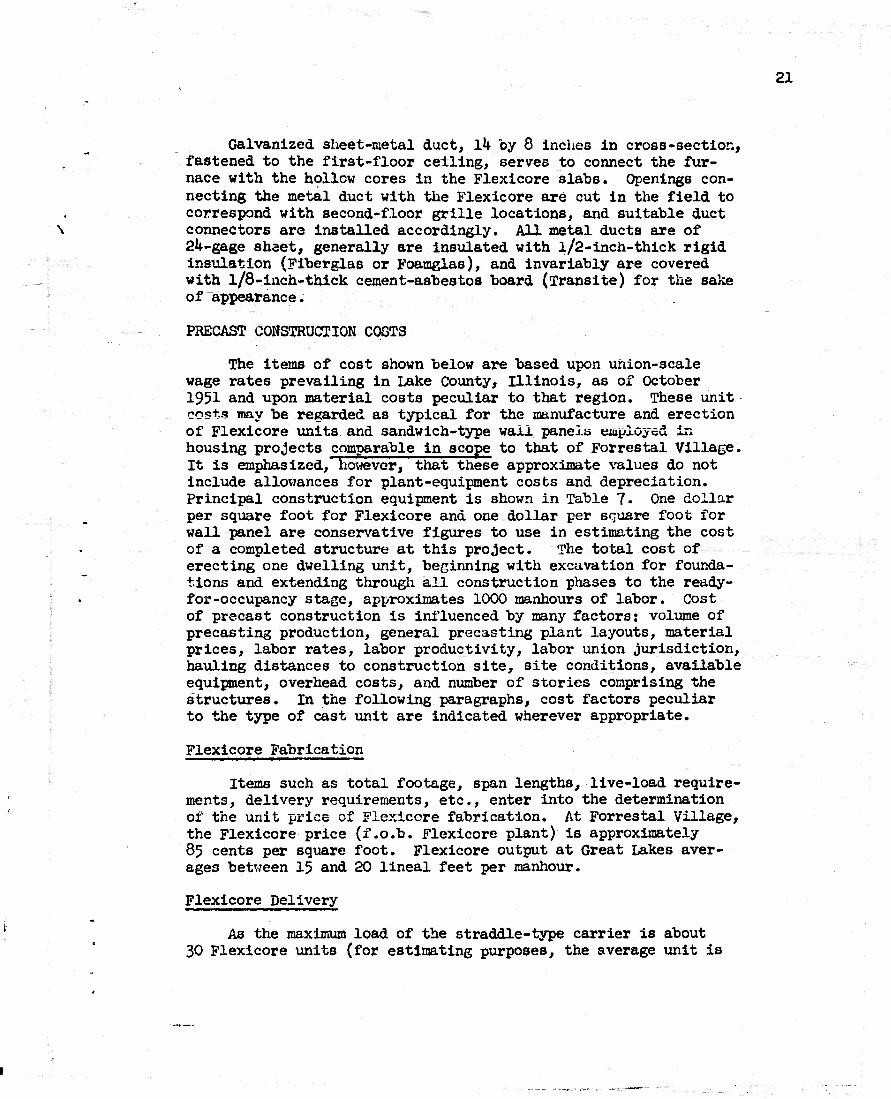
Galvanized sheet-metal duct, Ik by 8 inches in cross-section, fastened to the first-floor ceiling, serves to connect the fur- nace with the hollow cores in the Flexicore slabs. Openings con- necting the metal duct with the Flexicore are cut in the field to correspond with second-floor grille locations, and suitable duct connectors are installed accordingly. All metal ducts are of 2U-gage shaet, generally are insulated with l/2-inch-thick rigid insulation (Fiberglas or Foamglas), and invariably are covered with l/8-inch-thick cement-asbestos_ board (Transite) for the sake of appearance.
PRECAST CONSTRUCTION COSTS
The items of cost shown below are based upon union-scale wage rates prevailing in Lake County, Illinois, as of October 1951 and upon material costs peculiar to that region. These unit costs may be regarded as typical for the manufacture and erection of Flexicore units and sandwich-type wail panels employed in housing projects comparable in scope to that of Forrestal Village. It is emphasized, however, that these approximate values do not include allowances for plant-equipment costs and depreciation. Principal construction equipment is shown in Table 7- One dollar per square foot for Flexicore and one dollar per square foot for wall panel are conservative figures to use in estimating the cost of a completed structure at this project. The total cost of erecting one dwelling unit, beginning with excavation for founda- tions and extending through all construction phases to the ready- for-occupancy stage, approximates 1000 manhours of labor. Cost of precast construction is influenced by many factors: volume of precasting production, general precasting plant layouts, material prices, labor rates, labor productivity, labor union jurisdiction, hauling distances to construction site, site conditions, available equipment, overhead costs, and number of stories comprising the structures. In the following paragraphs, cost factors peculiar to the type of cast unit are indicated wherever appropriate.
Flexicore Fabrication
Items such as total footage, span lengths, live-load require- ments, delivery requirements, etc., enter into the determination of the unit price of Flexicore fabrication. At Forrestal Village, the Flexicore price (f.o.b. Flexicore plant) is approximately 85 cents per square foot. Flexicore output at Great Lakes aver- ages between 15 and 20 lineal feet per manhour.
Flexicore Delivery
As the maximum load of the straddle-type carrier is about 30 Flexicore units (for estimating purposes, the average unit is

22
28 feet long by 1-1/2 feet wide), each load represents not more than 1260 square feet of Flexicore. About 5-1/2 completed dwell- ing units per day is the erection average at this project, which represents an approximate total of 5900 square feet of Flexicore delivered a day; this total quantity is based on a weighted aver- age of 1077 square feet (gross) of Flexicore are*s for each dwell- ing unit and corresponds to not more than 5-1/2 carrier loads a day. Each carrier round-trip involves not more than ten miles; at $2.00 an hour for a carrier operator (excluding cost of the vehicle), delivery costs are about 0.3 cent per square foot of Flexicore. Movements are scheduled to conform to erection pro- gress, although an Important limiting facto*' is the efficiency of erection crews, deliveries amount to approximately JkO square feet of Flexicore per manhour.
Flexicore Erection
Erection at this project increases Flexicore cost by not more than 5 cents a square foot. The hourly cost of the erec- tion crew necessary for the laying, leveling, and grouting of the Flexicore floors and roofs is as follows:
— Hourly Hourly rate cost
^ laborers $1.85 Jtf.kO 1 brickmason (foreman) 2.75 2.75 1 rigger 2.75 2.75 1 crane operator 2.60 2.60
Total . $15.50
As Forrestal Village is a comparatively large undertaking in the housing field, as it involves fast assembly-line operations, and ab the majority of Flexicore units are of one size with relatively minor cutting to accommodate utility pipes, it may be assumed that the typical erection crew Installs about 5000 square feet of Flexi- core a day. Assuming a labor cost of $124.00 a day to erect at least 5000 square feet of Flexicore, the unit erection price is 2.5 cents a square foot; this figure includes hoisting grout to the Flexicore floor or roof slabs but does not include cost of the crane. Grout material will cost about 2 cents a square foot. Ceil' ing joints are not calked, but excess grout appearing on the under- side of the Flexicore slab is removed while plastic. Erection at this project approximates $0 square feet of Flexicore per manhour.
Wall-Panel Fabrication
At this project, an average of 30 sandwich-type wall panels are cast a day. The average dwelling unit utilizes approximately ll80 square feet of exterior wall area. Five dwelling units are produced a day, and the average dwelling unit requires six sandwich-
i •

type wall panels; the average wall-panel size is, therefore, 197 square feet. The daily cost of the casting crew is as fol- lows:
8 building laborers 2 structural-iron workers 2 cesient finishers 2 terrazzo workers 1 foreman
Hourly Total for rate 8 hours
$1.85 $118.1*0 2.75 44.00 2.55 40.80 2.55 40.80 3.00 24.00
Total $268.00
Estimated material costs per 1000 square feet of sandwich are:
23
1
i
-
- Unit price
$270.00 per 1000, delv'd
Total
1000 sq ft Foamglas $270.00 20 cu yd concrete 12.00 delv'd 240.00
2000 sq ft wire fabric 3.00 per 100, delv'd 60.00 2 steel door frames
(av 2'8" by 6«9") 15.00 30.00 3 steel window frames .
(av 3' by 8') 50.00 150.00 3 steel window frames • -- : .
(av 3« by 2') 15.00 45.00
. Total $795.00
Thus, excluding forms and equipmant involved, the approximate net cost (labor and materials) of fabricating an average wall panel (8 by 25 feet average dimensions) is $167.93# which is equivalent to 85 cents a square foot. Casting-yard output is approximately 50 square feet of sandwich-type wall per manhour.
Wall-Panel Lifting and Moving
The daily cost of the lifting crew is as follows:
t ...
4 structural-iron workers 1 crane operator 1 foreman
Hourly rate
$2.75 2.60 3.00
Total for 8 hours
$ 88.00 20.80 24.00
Total $132.80
24
I
The cost of vacuum pads and crane are excluded in this analysis. Excluding the cost of truck and semitrailer, the expense of a truck operator at $2.15 an hour amounts to $17.20 a day. Thus, to insure constant flow to the site of 30 panels a day, lifting and moving costs are $5.00 a panel, or 2.5 cents a square foot. Movement of wall panels from casting bed to the site is accom- plished at an average rate of 123 square feet per manhour.
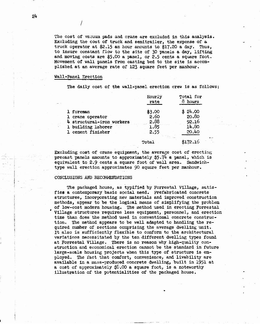
Wall-Panel Erection
The daily cost of the wall-panel erection crew is as follows:
Hourly Total for rate 8 hours
1 foreman $3.00 $ 24.00 1 crane operator 2.60 20.80 4 structural-iron workers 2.88 92.16 1 building laborer I.85 14.80 1 cement finisher 2.55 20.40
Total $172.16
Excluding cost of crane equipment, the average cost of erecting precast panels amounts to approximately $5-74 & panel, which is equivalent to 2.9 cents a square foot of wall area. Sandwich- type wall erection approximates 90 square feet per manhour.
CONCLUSIONS AND RECOMMENDATIONS
The packaged house, as typified by Forrestal Village, satis- fies a contemporary basic social need. Prefabricated concrete structures, incorporating new materials and improved construction methods, appear to be the logical means of simplifying the problem of low-cost modern housing. The method used in erecting Forrestal Village structures requires less equipment, personnel, and erection time than does the method used in conventional concrete construc- tion. The method appears to be well adapted to handling the re- quired number of sections comprising the average dwelling unit. It also is sufficiently flexible to conform to the architectural variations necessitated by the ten different dwelling types found at Forrestal Village. There is no reason why high-quality con- struction and economical erection cannot be the standard in future large-scale housing projects when this type of structure is em- ployed. The fact that comfort, convenience, and livability are available in a mass-produced concrete dwelling, built in 1951 at a cost of approximately $8.00 a square foot, is a noteworthy illustration of the potentialities of the packaged house.

25
The comments appearing "below are offered in an effort to dis- close improvements that perhaps could "be incorporated in future construction of this type.
Wall-Panel Concrete Materials
At Great Lakes, the exterior portions of the sandwich-type wall panels may be subject to severe deterioration caused by alter- nate wetting and drying and by freezing and thawing. Therefore, it appears that consideration could be given to factors that would
(a) minimize swelling and shrinking tendencies caused by wetting and drying by the use of vacuum-curing or high-pressure steam-curing; because of autoclave- size limitations, however, the wall-panel size would require considerable modification if high-pressure steam-curing were employed;
(b) increase resistance to freezing and thawing by means of air-entraining agents in the concrete mix; air- entrained concrete also would insure greater worka- bility at time of casting and would result in less bleeding and laitance.
More rapid erection of wall panels, with the added advantage of ease in handling, could be assured by using high-early-strength Portland cement (type III) in combination with lightweight concrete aggregate. However, the additional expense of hauling lightweight aggregates from distant sources might not justify their use.
Wall-Panel Insulation Materials
Obviously, the optimum use of materials used in fabricating the wall panels indicates the need for thinner wall-panel sections. In order to secure a thinner section that will properly withstand weathering and at the same time possess high fire resistance, the use of an appropriate type of rigid Fiberglas in place of Foam- glas as the sandwich core may have worthwhile possibilities.
Wall-Panel Joint Materials
A more effective design may be needed for both horizontal and vertical joints in order to insure a positive seal between panels at all times under all conditions. An improved vertical- joint seal could be obtained by inserting a stainless steel sheet, curved in cross-section, throughout the entire joint; the sxterior portion of the joint would be calked and the inner portion filled with a thermoplastic. A variation of this procedure would be the use of tongue-and-groove vertical joints which would serve as

26
self-aligning media; a premolded joint filler, in strip form and consisting of a compressed-cork or sponge-rubber core to insure constant resiliency, completely surrounded by rubberized aspbaltic sealing compound to insure the necessary adhesive properties, would be set in the grooves of the panels prior to erection. Sub- sequent to erection, the joints would be calked.
Flat-Roof Materials
Glass-fiber roofing, in place of the 3-ply> tar-and-gravel application, would result in a lighter roof load, a greater roof life expectancy, and a lowered maintenance cost. A Fiberglas built-up roof (for example, Owens-Corning Coromat) is, in effect, a monolithic sheet of asphalt incorporating random glass-fiber reinforcement. The inorganic fibers preclude alligatoring and wick-action, both of which are factors contributing to asphalt deterioration. The porosity of a built-up Fiberglas roof per- mits an even flow of asphalt throughout the roof mat;, and when saturated in this way with asphalt, the tensile strength of the glass mat compares favorably with that of conventional 3-ply> rag-felt construction. The use of Coromat would offer a roofing weight of approximately 120 pounds a roof square, whereas the 3-ply, tar-and-gravel construction results in a unit load of about 420 pounds a roof square.
Wall-Panel Design
If wall panels were pretensioned in the direction of the vertical dimension of the wall at tiie time of fabrication and post-tensioned horizontally after erection, it is believed that thinner sections could satisfactorily undergo present loads transmitted from Flexicore floor slabs. Such post-tensioning methods would presuppose the use of a satisfactory joint filler (resilient at all times) and a tongue-and-groove type of joint.

27
Table 1. Average Gradation of Aggregate for Ready-Mixed Concrete
Per cent Passing
Screen Coarse Fine
1/2 inch 100
3/8 inch 100
No. k 36 100
No. 8 3 92
No. 16 1 79
No. 30 — 60
No. 50 — IS
No. 100 — 1
Fineness modulus 5.6K 2.50

28
Table 2. Average Characteristics of Aggregate for Ready-Mixed Concrete
Characteristic
Unit veight, rodded, room dry, lb per cu ft
Bulk spec, grav., saturated- surface -dry
?er cent voids
Coarse Fine
103.5 109.5
2.67 2.67
37.8 3^.2
not observed negligible
Deleterious substances, per cent by weight
Soft Fragments Clay lumps Coal and lignite Shale Chert Material finer than no. 200
1.3 0.3 none none none none none none 1.8 0.3 0.5 0.4
Surface moisture content, per cent by weight (field condition) 3.0

29
Table 3« Average Mix Design for Ready-Mixed Concrete
G Feature
Foundations
Ground floors
Entrance platforms
Precast wall sections
Stairs & stair landings
Canopies & chimney enclosures
Garage precast walls
Garage precast roofs
to <D Pi
to si m -P
O -P U CO
2,000
2,500
3,000
4,000
4,000
5
5
4
-I
S3 a a)
H <ti -p c O O
a •H s
3 o
P.
4.00
4.50
5.50
6.75
6.75
to a> -p
g a g a>
3 to S a]
1
1
1
3/3
3/8
•p c 8~ a> -p o * i u >>
•p «~' cU ? o
•H +s +>
25 fn
0.75
O.67
0.53
0.50
0,50
13
a a) ?** H -P
1.4
1.4
1.5
l.l
1.1
-p cs
<u o to-p
9.0
7.8
6.2
4.9
4.9
4,000 3 6.75 3/8 0.50 1.1 4.9
4,000 3 6.75 3/8 0.50 l.l 4.9
4,000 3 6.75 3/8 0.50 l.l 4.9
a H •P o Pi-P
P. S >> o En o
I
I
I
I
IIIb or I
III* or I
IIIb or I
IIIb or I
a. Aggregate-cement and gravel-sand ratio values are based on saturated- surface-dry aggregate.
b. Type-Ill portland cement indicates mold removal at age 24 hours.

30
Table h. Average Gradation of Aggregate for Flexicore Concrete
Screen
3/8 inch
No. k
No. 10
No. 16
No. 30
No. 50
No. 100
Fineness modulus
Per cent Passing
Coarse Fine
100 —
25 100
3 87
/n DO
5.75
50 (est.)
17
3
2.75

31
Table 5. Average Characteristics of Aggregate for Flexlcore Concrete
Characteristics
Unit weight, rodded, room-dry, lb per cu ft
Bulk spec, grav., saturated- surface dry
Per cent voids
Organic impurities, per cent
Deleterious substances, per cent by weight
Coarse Fine
110.0 112.0
2.73 2.6?
Not observed Not observed
1.2 0.07
Soft fragments 1.1 .Ok Clay lumps none none Coal and lignite none none Shale none 0.1 Chert 0.1 0.1 Material finer than no. 200 none 1.0
.ce moisture content, per cent weight (field condition) none 3.0 (est.)
OT

32
Table 6. Average Mix Design of Flexicore Concrete
7-day compressive strength, psi
28-day compre3sive strength, psi
Slump, inches
Cement content, sacks per cubic yard
Maximum size of aggregate, inches
Water-csment ratio (net), "by weight
Gravel-sand ratio, by weight
Aggregate-cement ratio, by weight
Type Portland cement
Brand portland cement
Mixing time per batch, minutes
Quantity mixed, cubic yards per hour
3,090
4>50
2-1/2
7A0
3/8
0.4?
1.80
4.37
I
Universal Atlas
Approx. U-l/2
33
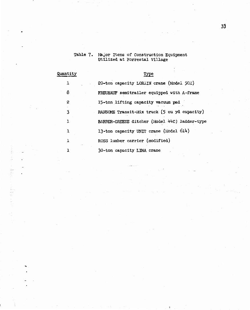
Table 7. Major Items of Construction Equipment Utilized at Forrestal Village
Quantity Type
1 20-ton capacity LORAIN crane (Model 50IC)
8 FREUHAUF semitrailer equipped with A-frame
2 15-ton lifting capacity vacuum pad
3 RANSOME Transit-Mix truck (5 cu yd capacity)
1 BARBER-GREENE ditcher (Model kkc) ladder-type
1 13-ton capacity UNIT crane (Model 611*)
1 ROSS lumber carrier (modified)
1 30-ton capacity LIMA crane

3*
Table 8. Physical Properties of Foamglas
Characteristics Average Value
Unit weight, lb per cu ft 10
Specific gravity 0.l6
Coefficient of expansion, in./in./<teg F h x 10"6
Compressive strength, psi 140
Flexural strength, psi 100
Shear strength, psi 64
Tensile strength, psi 84
Modulus of elasticity, psi 200,000

35
Foctmglas insulation
waterproof membrane
Figure 1. Typical foundation-wall section and bearing wall.
36
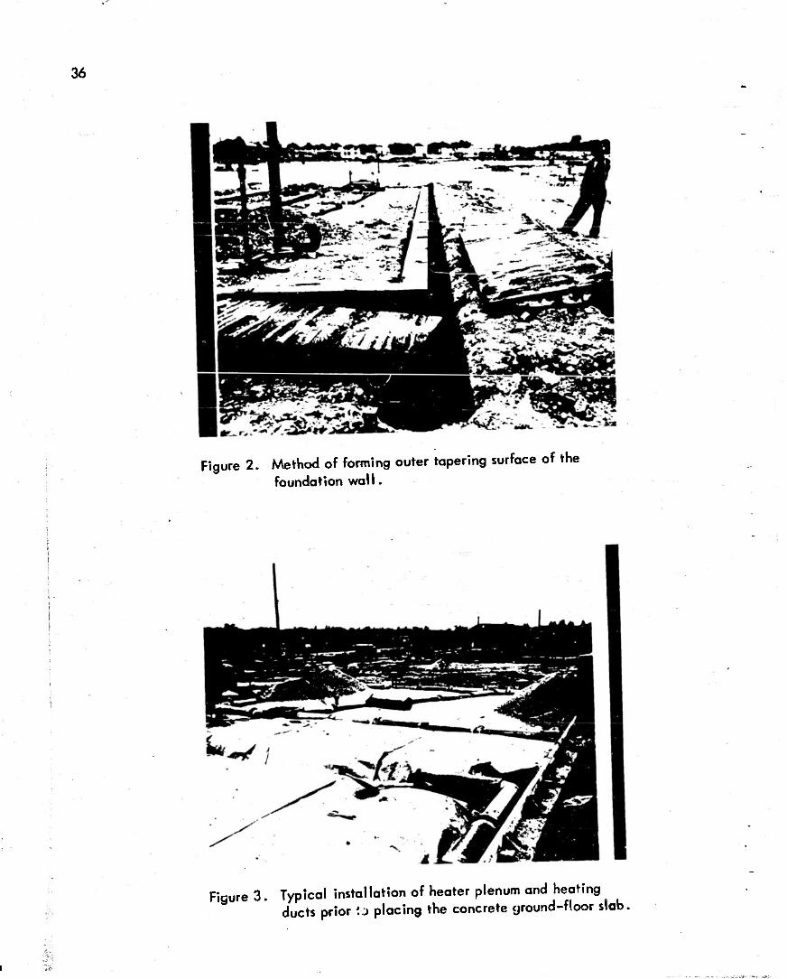
Figure 2. Method of forming outer tapering surface of the foundation wall.
i-
Figure 3. Typical installation of heater plenum and heating ducts Drior \i placing the concrete ground-floor slab,

37
Figure 4. Finishing a concrete ground-floor slab.
Figure 5. Wall-panel forms preparatory to concrete placement.

38
Figure 6. Installation of Foarnglas in precast wall panels.
Figure 7. Surface texture of wall-panel exterior face.

39
1 Figure 8. Loading completed wall panel onto a semitrailer by
means of a vacuum pad.
^
Figure 9. Removing wall panel from trailer preparatory to erection.

40
/A\
Figure 10. Placement of 1/2-inch-thick mortar bed upon foundation
wall prior to the erection of wall panels at first-floor level.
Figure 11 . Push-pull type of tie rods used for shoring wall panels prior to welding operations.

41
Figure 12. Welding flat connectors to steel plates embedded in panels; note detail of shoring attached to wall panel.

'.; ...... ;s_—( --'-::.••**•.• ':"-":'"**»i..-..
42
5
I 5 j
\
••O-T*.
>/WKAA/\7T7WTTPl
Q;V°
o -•
o
«
• P
3 c
o
E
« o
* o • * -c o
Jo e "5. 5 e « O X
I CO
X (
/ I V
,&' I
0 •'
'. ' >
3 : •
i t *
i
• 4
Ol
V*
0 .
o
o c o
vfc
o
D
C o «• u t) c c o u
**. o
J a.
~o u
"5.
3

43
<
<
:•••:.
n o o
gu. E g
g mam J 3 a
•E
I o C7>
O
J_Li ^r
3* w wwv
I J S JJ M
j
s o §
§ u "5 o '5. >»

*ww«« «aK«M»wi«tfW»i'<X!*rwiM*W-i ''WWWl'MIWiWfc..,
44 I
I
1 M
1 s I I
"8 I I
* i,

• !>:»*K-*,v.»
45
}•
8 J 3 «• C
M JO » E 8
5 -8
v/\/\'/\/\y\/\y « O -O
o
I i x
u
! u "5 o 5.
S
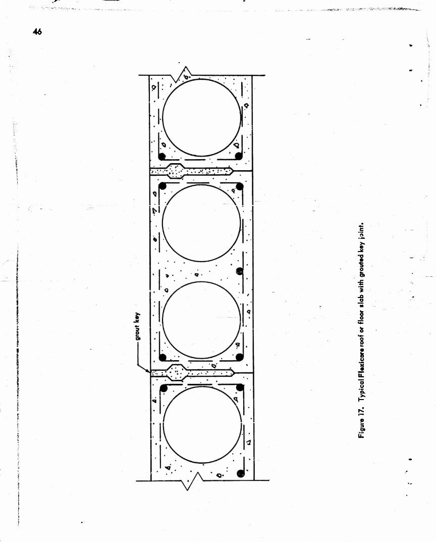
,a«>7:' •zs\<iz&i3,&&:'4
46
'5
o
JO o
s fa.
u
o o 'S.
p 5

47
Figure 13. Positioning second-floor Flexicore units,
Figure 19. Grouting joints between second-floor Flexicore units.

48
Figure 20. Erection of wall panels at second-floor level of quadruplex structure.
f f m»
Figure 21 . Use of embedded hooks during erection of side wall

49
* t
Figure 22. Positioning Flexicore flat-roof units.
Figure 23. Aerial view of partly completed quadruplex structure.

50
Figure 24, Completed quadruplex structure, showing architectural • treatment and appearance of wall-panel joints after
calking.
^VV.\-VUiiTO777F77^
Figure 25. Wood-frame hipped-roof surmounting the Flexicore
cei ling slab in a single-story dwelling,

51
Figure 26. Eave detail of hipped-roof structure, showing rolled batt insulation packed into open ends of Flexicore units.
Figure 27. Typical duplex and quadruplex structures.

52
Figure 28. Installation of partition walls in a typical dwelling unit.
«*»i norro lino PT «usu CALIF 661/53