preface - images-na.ssl-images-amazon.com
TRANSCRIPT

PrefaceAbout SunFounderSunFounder is a technology company focused on Raspberry Pi and Arduino open sourcecommunity development. Committed to the promotion of open source culture, we strive tobring the fun of electronics making to people all around the world and enable everyone tobe a maker. Our products include learning kits, development boards, robots, sensormodules and development tools. In addition to high quality products, SunFounder alsooffers video tutorials to help your own project. If you have interest in open source or makingsomething cool, welcome to join us! Visit www.sunfounder.com for more!
About Starter KitThis starter kit is suitable for SunFounder Uno, SunFounder Mega 2560, SunFounderDuemilanove and SunFounder Nano. All the code in this user guide is also compatible withthese boards.
Our SunFounder board is fully compatible with Arduino.
This kit walks you through the basics of using the SunFounder in a hands-on way. You'll learnthrough building several creative projects. The kit includes a selection of the most commonand useful electronic components. Starting from the basics of electronics, to more complexprojects, the kit will help you control the physical world with components.
In this book, we will show you circuits with both realistic illustrations and schematic diagrams.You can go to our official website www.sunfounder.com to download related code byclicking LEARN -> Get Tutorials->Starter Kit V2.0 for Arduino and watch related videos byclicking VIDEO.
Free Support
If you have any TECHNICAL questions, add a topic under FORUM section on ourwebsite and we'll reply as soon as possible.
For NON-TECH questions like order and shipment issues, please send an email [email protected]. You're also welcomed to share your projects on FORUM.
Rept 2.0
ContentsComponents List.............................................................................................................................................. 1
Get Started........................................................................................................................................................6
Arduino...............................................................................................................................................6
Description.........................................................................................................................................6
SunFounder Arduino Board...........................................................................................................6
Install Arduino IDE............................................................................................................................ 8
Plug in the Board..............................................................................................................................9
How to Use the IDE..........................................................................................................................9
Lesson 1 Button...............................................................................................................................................12
Lesson 2 Flowing LED Lights.........................................................................................................................17
Lesson 3 Buzzer...............................................................................................................................................19
Lesson 4 Photoresistor...................................................................................................................................22
Lesson 5 RGB LED...........................................................................................................................................25
Lesson 6 Relay................................................................................................................................................ 29
Lesson 7 Tilt-Switch.........................................................................................................................................33
Lesson 8 Servo................................................................................................................................................ 36
Lesson 9 Thermistor........................................................................................................................................39
Lesson 10 Automatically Tracking Light Source....................................................................................42
Lesson 11 Light Alarm...................................................................................................................................45
1
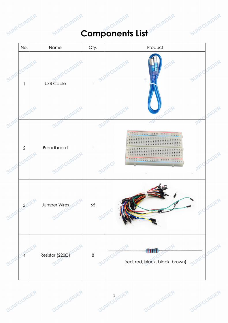
Components ListNo. Name Qty. Product
1 USB Cable 1
2 Breadboard 1
3 Jumper Wires 65
4 Resistor (220Ω) 8(red, red, black, black, brown)
2
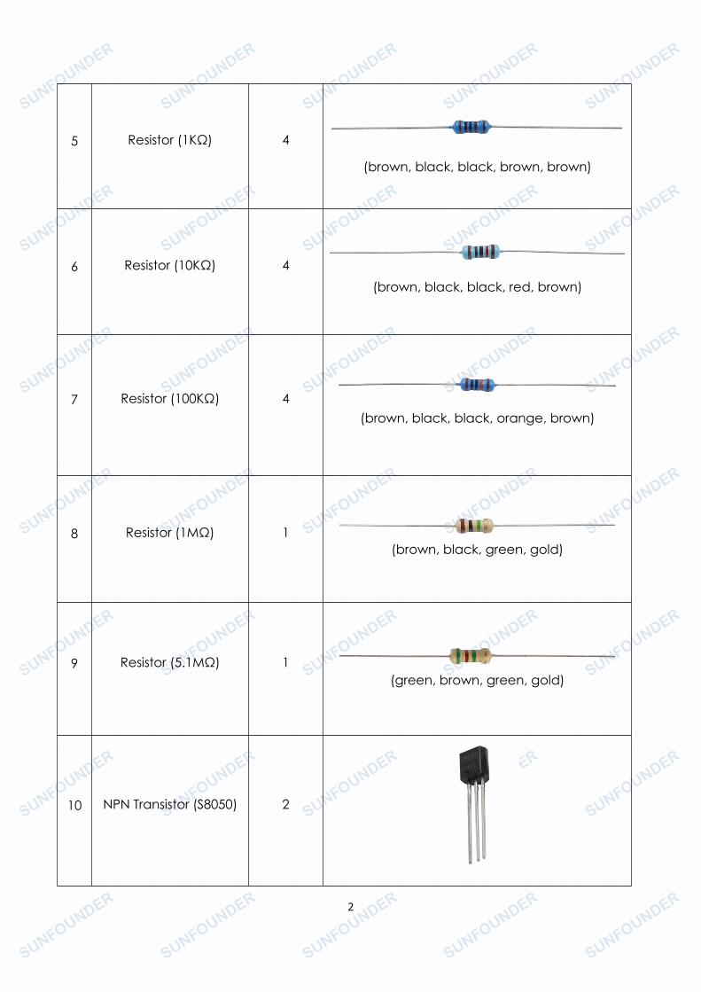
5 Resistor (1KΩ) 4
(brown, black, black, brown, brown)
6 Resistor (10KΩ) 4(brown, black, black, red, brown)
7 Resistor (100KΩ) 4(brown, black, black, orange, brown)
8 Resistor (1MΩ) 1(brown, black, green, gold)
9 Resistor (5.1MΩ) 1(green, brown, green, gold)
10 NPN Transistor (S8050) 2

3
11 FET Transistor (2N7000) 1
12Diode Rectifier
(1N4007) 2
13 Diode (Zener) 1
14 Tilt Switch 1
15Photoresistor(Photocell) 1

4
16 Thermistor 1
17 Button 2
18Rotary Knob
(Potentiometer)2
19 Servo Motor 1
20 RGB LED 1
5
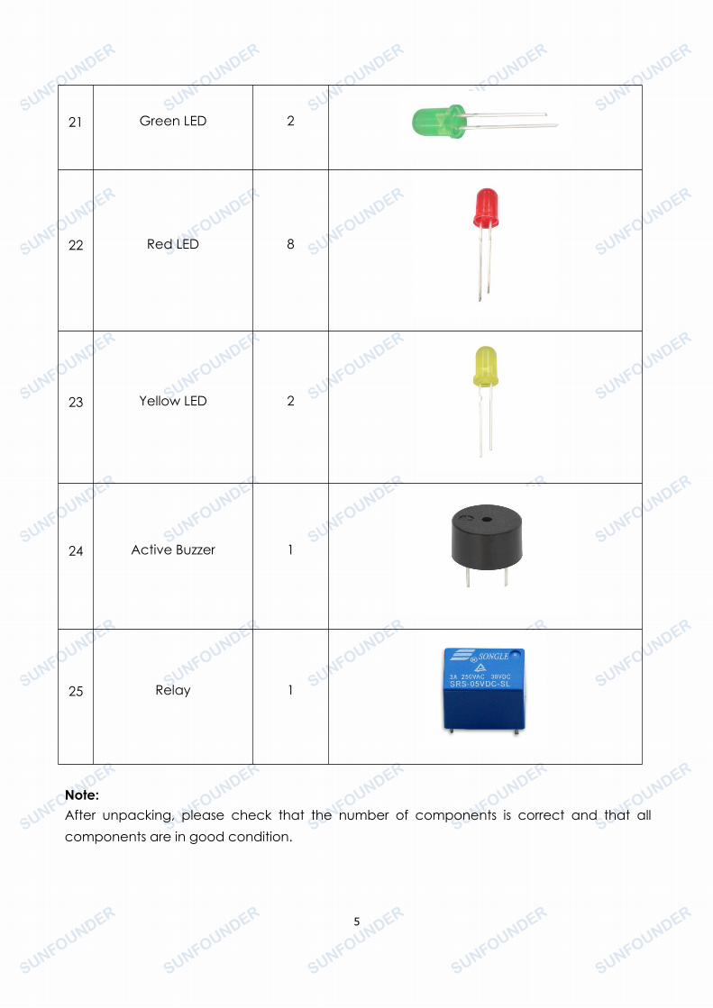
21 Green LED 2
22 Red LED 8
23 Yellow LED 2
24 Active Buzzer 1
25 Relay 1
Note:After unpacking, please check that the number of components is correct and that allcomponents are in good condition.
6
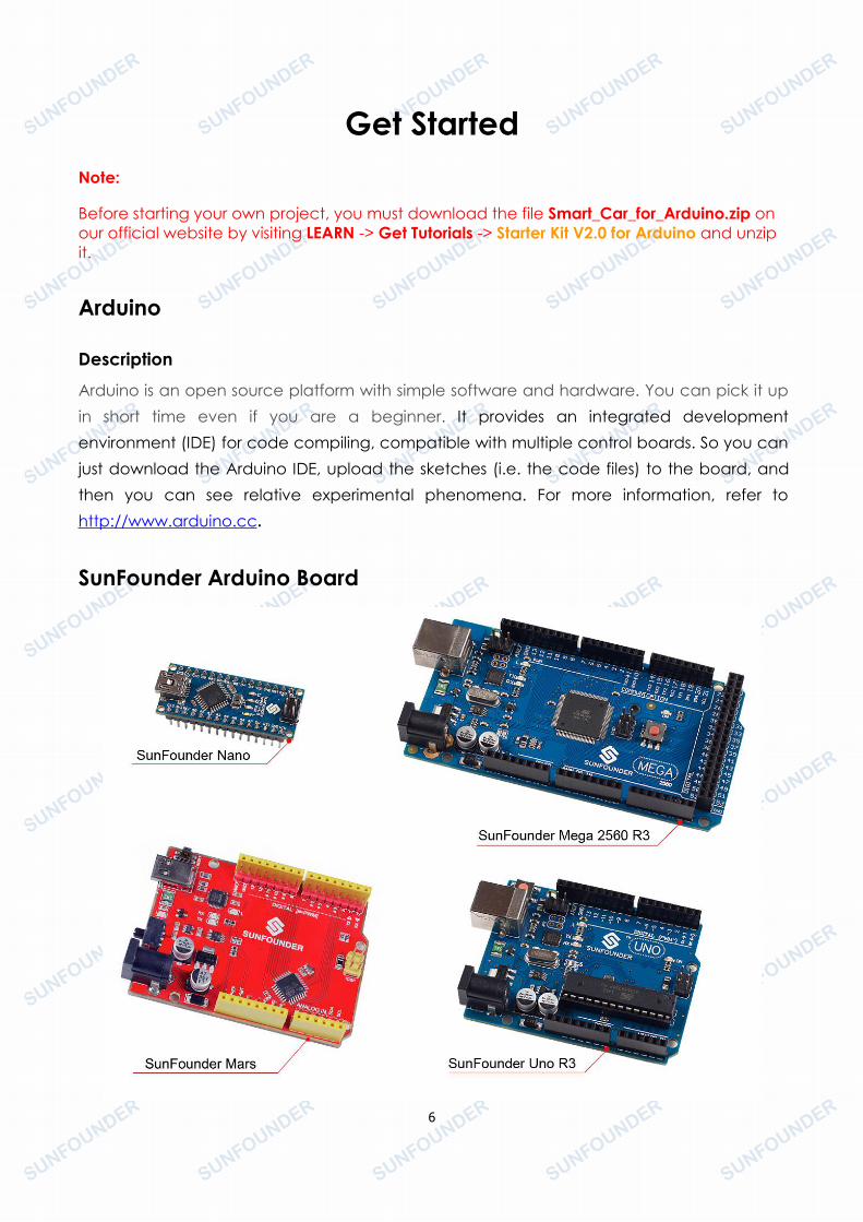
Get StartedNote:
Before starting your own project, you must download the file Smart_Car_for_Arduino.zip onour official website by visiting LEARN -> Get Tutorials -> Starter Kit V2.0 for Arduino and unzipit.
Arduino
DescriptionArduino is an open source platform with simple software and hardware. You can pick it upin short time even if you are a beginner. It provides an integrated developmentenvironment (IDE) for code compiling, compatible with multiple control boards. So you canjust download the Arduino IDE, upload the sketches (i.e. the code files) to the board, andthen you can see relative experimental phenomena. For more information, refer tohttp://www.arduino.cc.
SunFounder Arduino Board
7
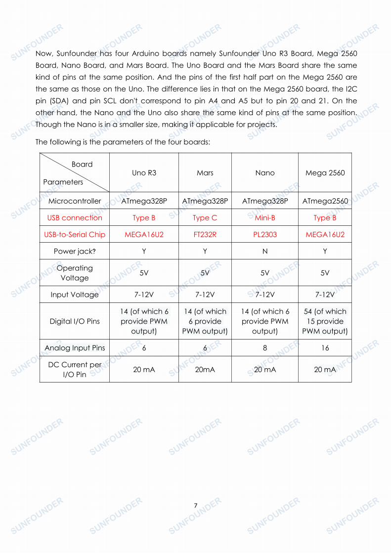
Now, Sunfounder has four Arduino boards namely Sunfounder Uno R3 Board, Mega 2560Board, Nano Board, and Mars Board. The Uno Board and the Mars Board share the samekind of pins at the same position. And the pins of the first half part on the Mega 2560 arethe same as those on the Uno. The difference lies in that on the Mega 2560 board, the I2Cpin (SDA) and pin SCL don't correspond to pin A4 and A5 but to pin 20 and 21. On theother hand, the Nano and the Uno also share the same kind of pins at the same position.Though the Nano is in a smaller size, making it applicable for projects.
The following is the parameters of the four boards:
Board
ParametersUno R3 Mars Nano Mega 2560
Microcontroller ATmega328P ATmega328P ATmega328P ATmega2560
USB connection Type B Type C Mini-B Type B
USB-to-Serial Chip MEGA16U2 FT232R PL2303 MEGA16U2
Power jack? Y Y N Y
OperatingVoltage
5V 5V 5V 5V
Input Voltage 7-12V 7-12V 7-12V 7-12V
Digital I/O Pins14 (of which 6provide PWM
output)
14 (of which6 provide
PWM output)
14 (of which 6provide PWM
output)
54 (of which15 provide
PWM output)
Analog Input Pins 6 6 8 16
DC Current perI/O Pin
20 mA 20mA 20 mA 20 mA
8
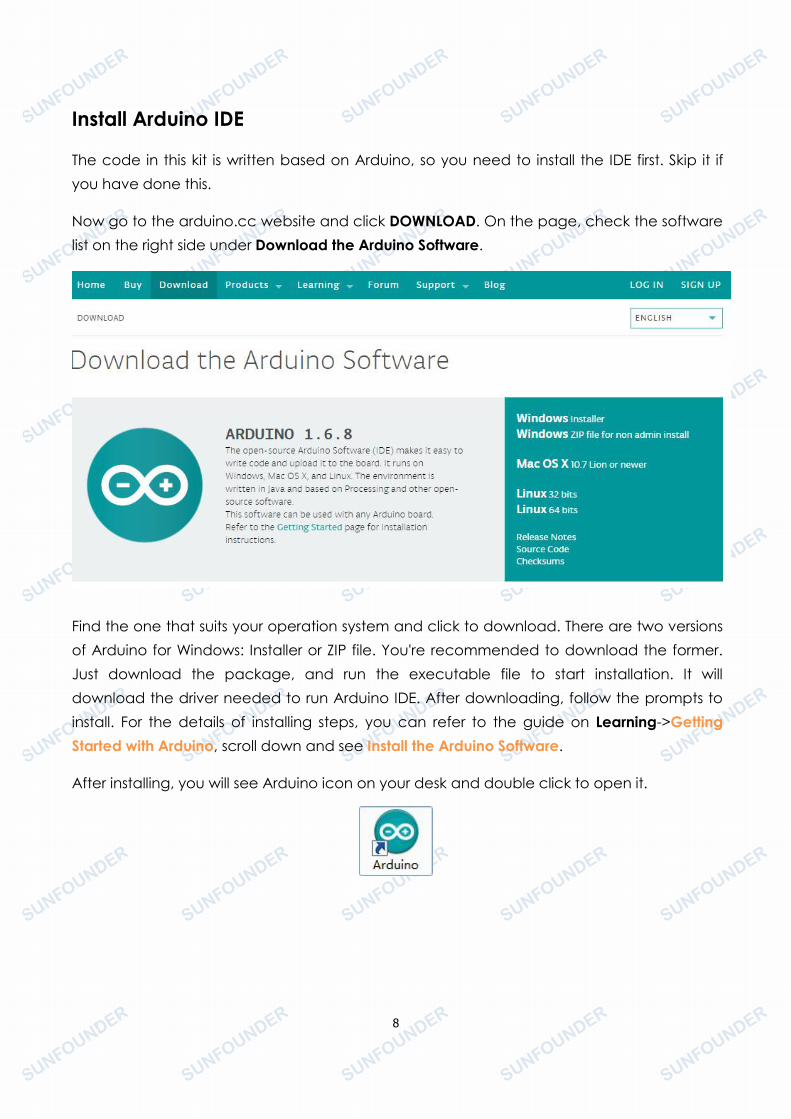
Install Arduino IDE
The code in this kit is written based on Arduino, so you need to install the IDE first. Skip it ifyou have done this.
Now go to the arduino.cc website and click DOWNLOAD. On the page, check the softwarelist on the right side under Download the Arduino Software.
Find the one that suits your operation system and click to download. There are two versionsof Arduino for Windows: Installer or ZIP file. You're recommended to download the former.Just download the package, and run the executable file to start installation. It willdownload the driver needed to run Arduino IDE. After downloading, follow the prompts toinstall. For the details of installing steps, you can refer to the guide on Learning->GettingStarted with Arduino, scroll down and see Install the Arduino Software.
After installing, you will see Arduino icon on your desk and double click to open it.
9
Plug in the Board
Connect the control board to your computer with a USB cable. If you use Uno, Mega2560or Mars as the control board, the system will automatically install the driver when you plug itin. After a while, a prompt will show up at the bottom right corner telling you which port theboard locates at. If the control board is Nano, then you need to install the driver by yourself.For more details, you can refer to WIKI on our website www.sunfounder.com.
How to Use the IDE
Double-click the Arduino icon (arduino.exe) created by the installation process
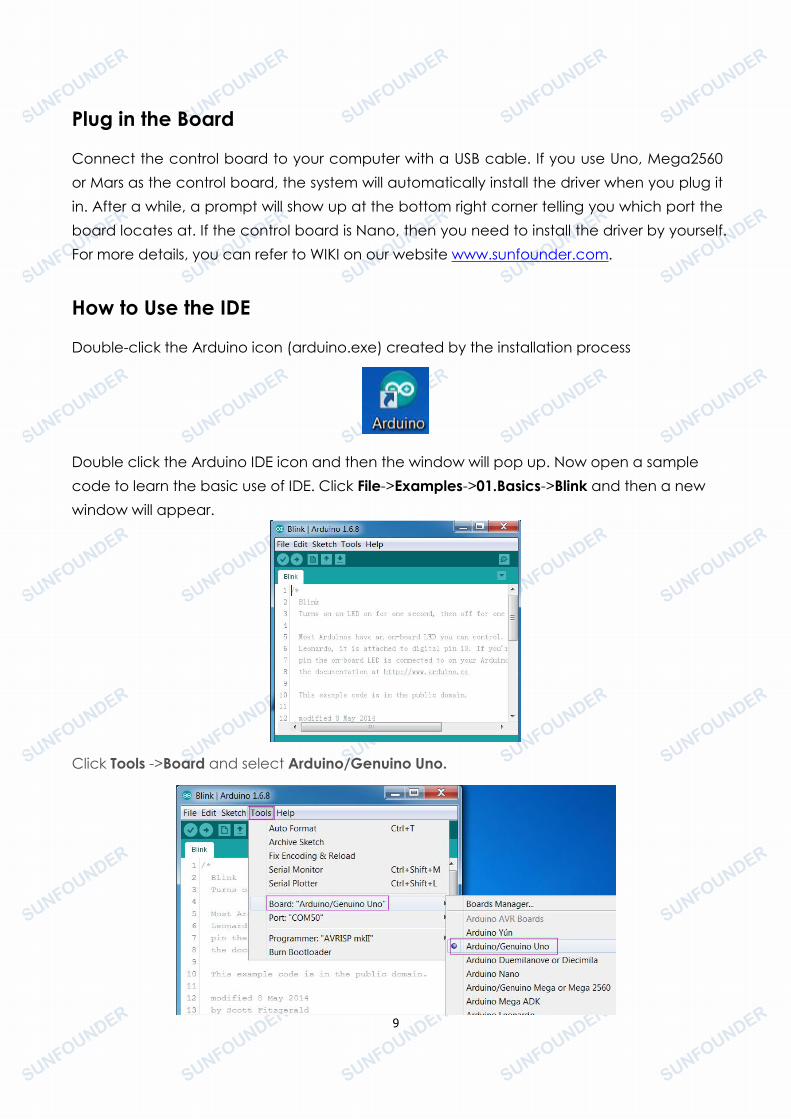
Double click the Arduino IDE icon and then the window will pop up. Now open a samplecode to learn the basic use of IDE. Click File->Examples->01.Basics->Blink and then a newwindow will appear.
Click Tools ->Board and select Arduino/Genuino Uno.

10
Then select Tools ->Port.
Click the Upload icon to upload the code to the board. And the icon Compile to compilesketches (usually used to refer to a code file), which always checks the code. Also whenyou click Upload, the code will be compiled. The sketches can be uploaded to the boardwhen there is nothing wrong with them. Therefore, generally you just need to click Upload.During the upload, the TX LED and the RX LED will be alternately flickering. It means theboard is sending signal to the computer and then receives the signal from the computer.After upload is completed, the two LEDs will go out.
If "Done uploading" appears at the bottom of the window, it means the sketch has beensuccessfully uploaded. And if you see the pin 13(L) LED starts to flicker, it means the codeshave been successfully run.
11
For more details about Arduino IDE, go to Learning->Getting started->Foundation on thearduino.cc and click Arduino Software (IDE) on the pagehttp://www.arduino.cc/en/Guide/Environment
If your sketch fails upload, on the same page click Troubleshootinghttp://www.arduino.cc/en/Guide/Troubleshooting.
Notes:
- If your computer is running on the Windows XP system, the new version IDE will prompterrors when running the code. You are recommended to download the Arduino 1.0.5or Arduino 1.0.6. Or you can also upgrade your Window system.
- All the experiments in this kit are done with SunFounder Uno R3 board, but they are alsocompatible with SunFounder Mega 2560, SunFounder Mars, SunFounder Nano and allofficial Arduino Boards. All the code included in this kit works with these boards.
So what does COMPATIBLE mean here? It means you can use any of the three boardsto do the same experiment with the same wiring. Simply put, if the wire is connected toPin 12 of Uno in the user manual, likewise, you can connect it to Pin 12 on any otherofficial Arduino boards you are using. Then open the corresponding sketch and uploadthem.
12
Lesson 1 Button
IntroductionIn this experiment, we will learn how to turn an LED on/off by using an I/O port and a button.The "I/O port" refers to the INPUT and OUTPUT port. Here the INPUT port of the SunFounderUno board is used to read the output of an external device. Since the board itself has anLED (connected to Pin 13), you can use this LED to do this experiment for convenience.
Components- 1 * SunFounder Uno board- 1 * USB cable- 1 * Button- 1 * Resistor (10kΩ)- Jumper wires- 1 * Breadboard
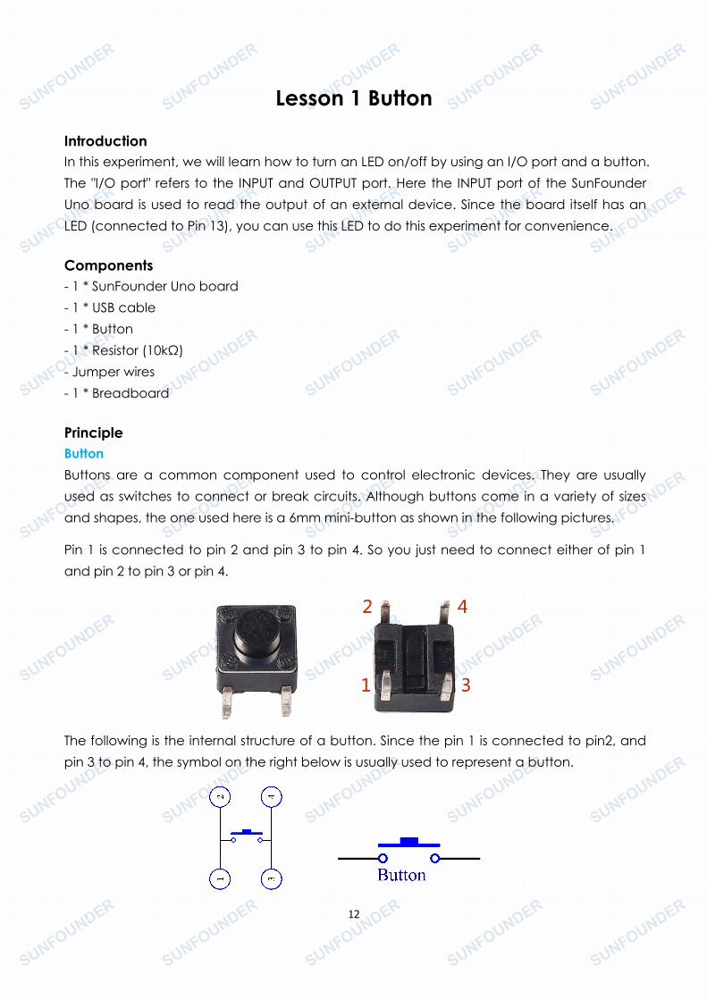
PrincipleButtonButtons are a common component used to control electronic devices. They are usuallyused as switches to connect or break circuits. Although buttons come in a variety of sizesand shapes, the one used here is a 6mm mini-button as shown in the following pictures.
Pin 1 is connected to pin 2 and pin 3 to pin 4. So you just need to connect either of pin 1and pin 2 to pin 3 or pin 4.
The following is the internal structure of a button. Since the pin 1 is connected to pin2, andpin 3 to pin 4, the symbol on the right below is usually used to represent a button.
13
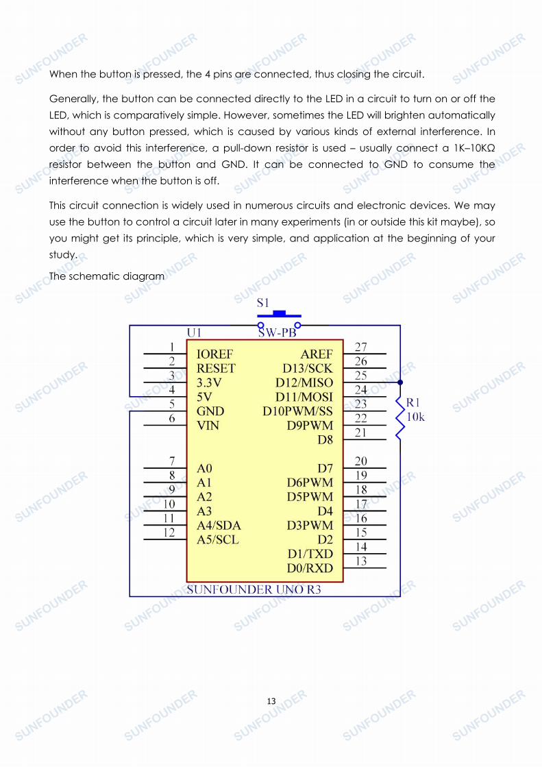
When the button is pressed, the 4 pins are connected, thus closing the circuit.
Generally, the button can be connected directly to the LED in a circuit to turn on or off theLED, which is comparatively simple. However, sometimes the LED will brighten automaticallywithout any button pressed, which is caused by various kinds of external interference. Inorder to avoid this interference, a pull-down resistor is used – usually connect a 1K–10KΩresistor between the button and GND. It can be connected to GND to consume theinterference when the button is off.
This circuit connection is widely used in numerous circuits and electronic devices. We mayuse the button to control a circuit later in many experiments (in or outside this kit maybe), soyou might get its principle, which is very simple, and application at the beginning of yourstudy.
The schematic diagram
14
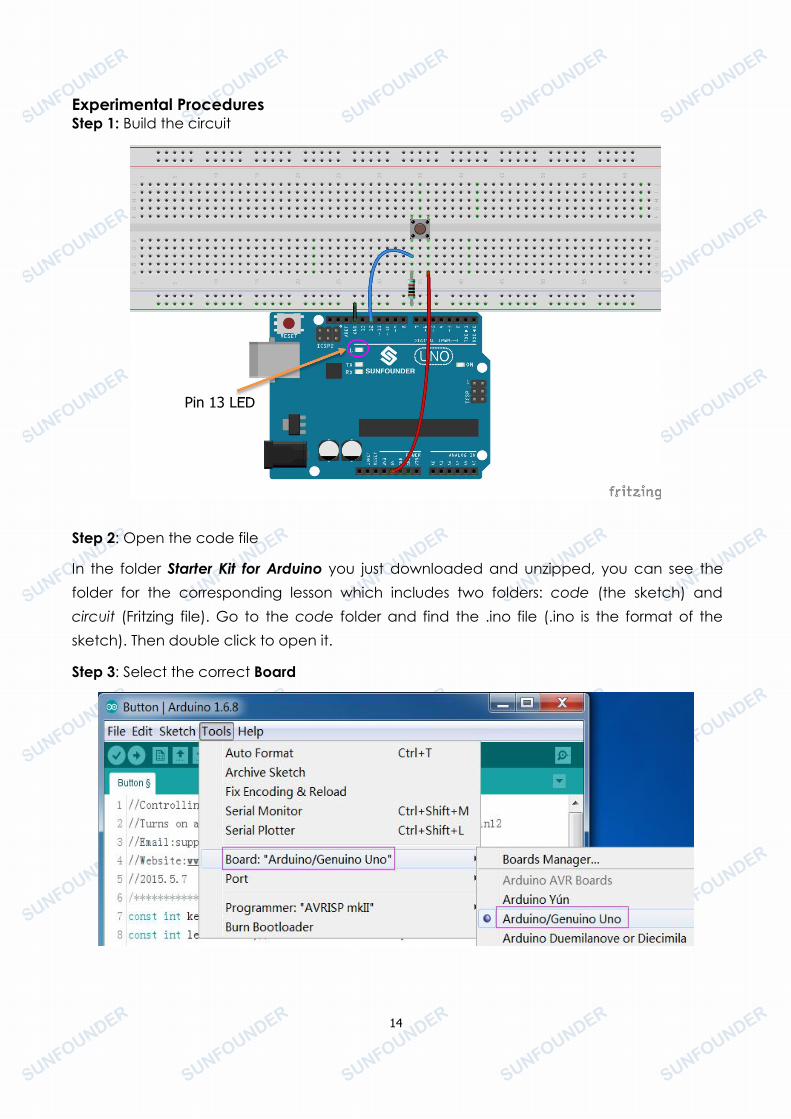
Experimental ProceduresStep 1: Build the circuit
Step 2: Open the code file
In the folder Starter Kit for Arduino you just downloaded and unzipped, you can see thefolder for the corresponding lesson which includes two folders: code (the sketch) andcircuit (Fritzing file). Go to the code folder and find the .ino file (.ino is the format of thesketch). Then double click to open it.
Step 3: Select the correct Board
Pin 13 LED
15
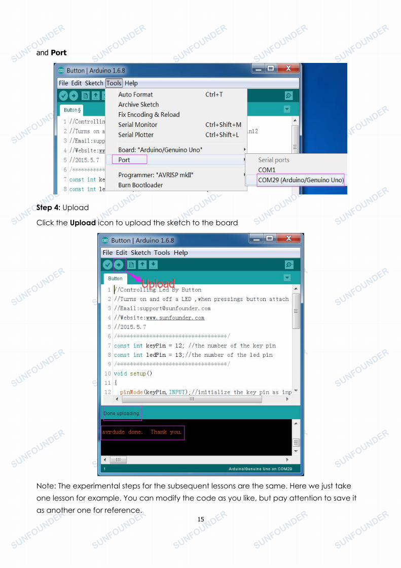
and Port
Step 4: Upload
Click the Upload icon to upload the sketch to the board
Note: The experimental steps for the subsequent lessons are the same. Here we just takeone lesson for example. You can modify the code as you like, but pay attention to save itas another one for reference.
16
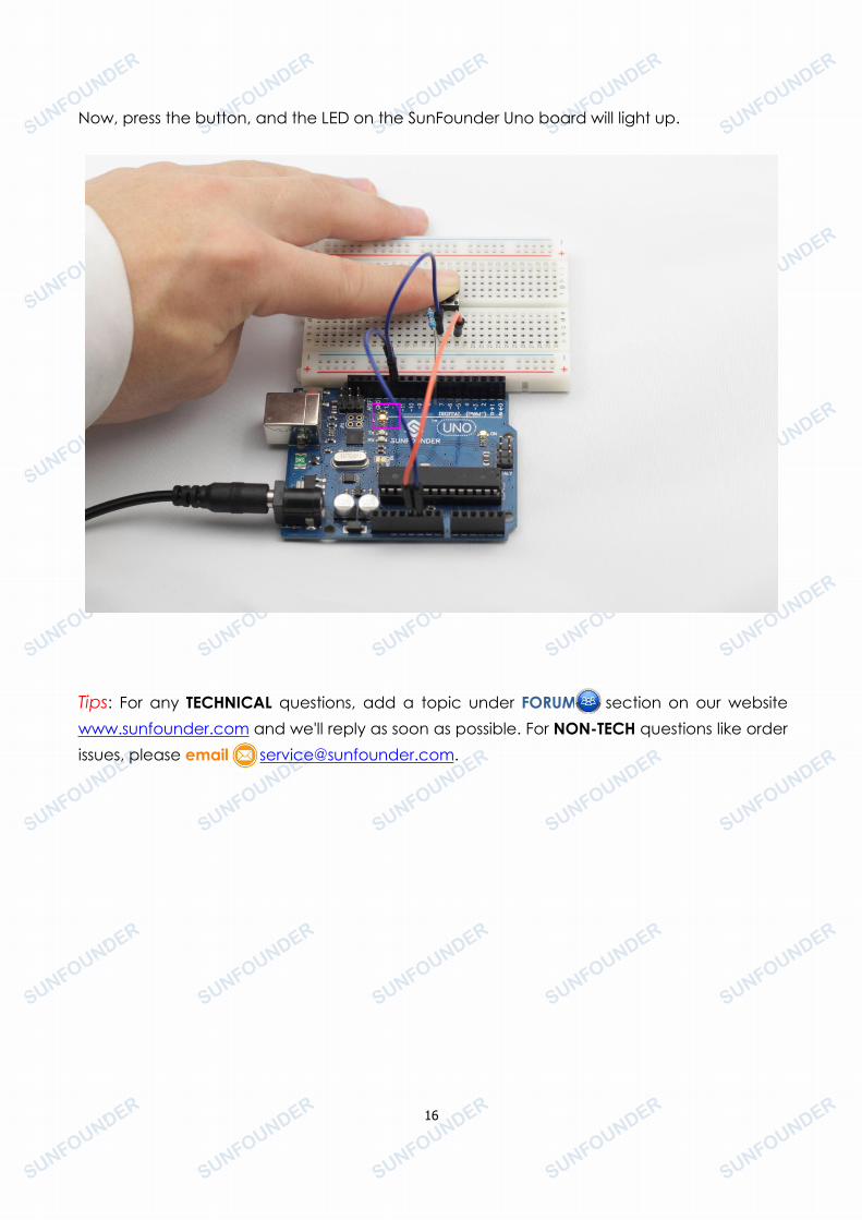
Now, press the button, and the LED on the SunFounder Uno board will light up.
Tips: For any TECHNICAL questions, add a topic under FORUM section on our websitewww.sunfounder.com and we'll reply as soon as possible. For NON-TECH questions like orderissues, please email [email protected].
17
Lesson 2 Flowing LED Lights
IntroductionIn this lesson, you will conduct a simple yet interesting experiment – using LEDs to createflowing LED lights. As the name implies, these flowing lights are made up of eight LEDs in arow which successively light up and dim one after another, just like flowing water.
Components- 1 * SunFounder Uno board- 1 * Breadboard- Jumper wires- 8 * LED- 8 * Resistor (220Ω)- 1 * USB cable
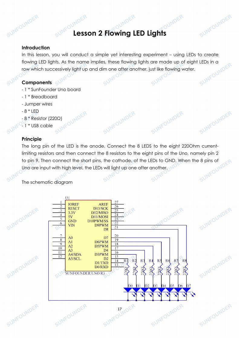
PrincipleThe long pin of the LED is the anode. Connect the 8 LEDS to the eight 220Ohm current-limiting resistors and then connect the 8 resistors to the eight pins of the Uno, namely pin 2to pin 9. Then connect the short pins, the cathode, of the LEDs to GND. When the 8 pins ofUno are input with high level, the LEDs will light up one after another.
The schematic diagram
18
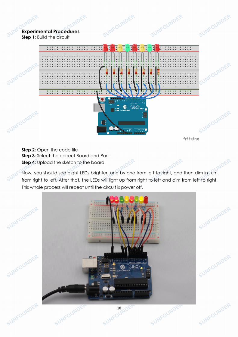
Experimental ProceduresStep 1: Build the circuit
Step 2: Open the code fileStep 3: Select the correct Board and PortStep 4: Upload the sketch to the board
Now, you should see eight LEDs brighten one by one from left to right, and then dim in turnfrom right to left. After that, the LEDs will light up from right to left and dim from left to right.This whole process will repeat until the circuit is power off.
19
Lesson 3 BuzzerIntroductionA buzzer is a great tool in your experiments whenever you want to make some sounds. .
Components- 1 * SunFounder Uno board- 1 * Breadboard- 1 * USB data cable- 1 * Buzzer (Active)- Jumper wires
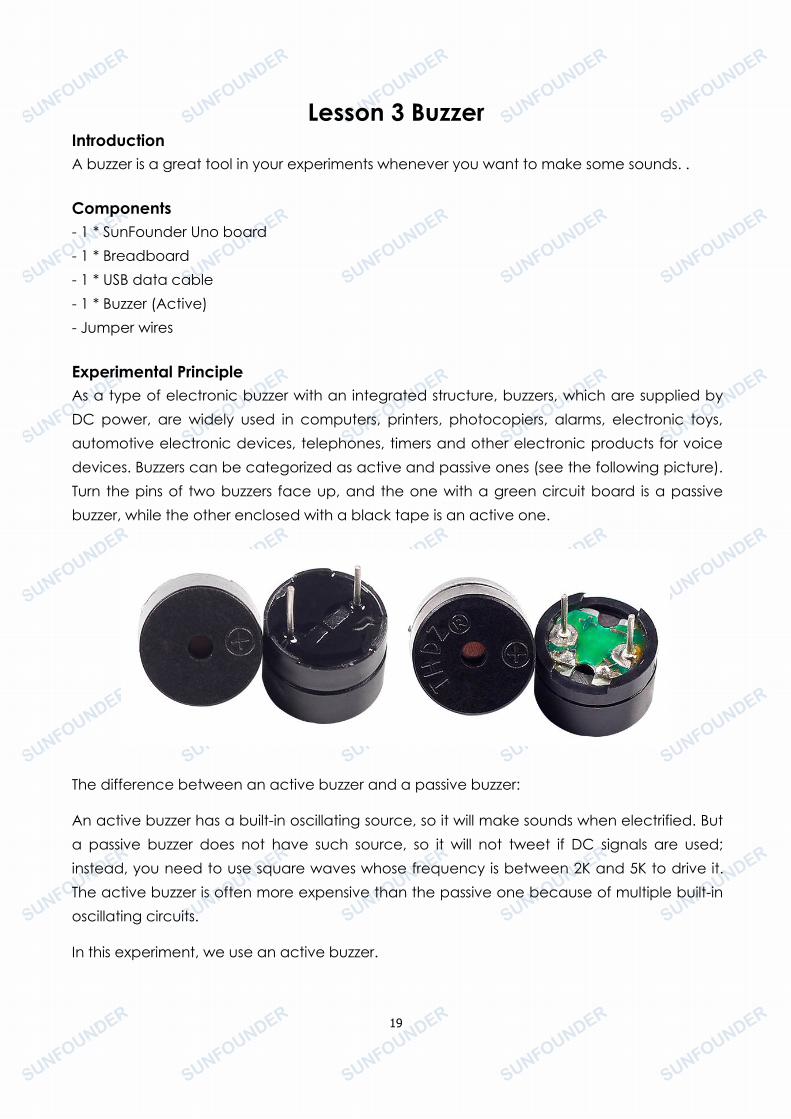
Experimental PrincipleAs a type of electronic buzzer with an integrated structure, buzzers, which are supplied byDC power, are widely used in computers, printers, photocopiers, alarms, electronic toys,automotive electronic devices, telephones, timers and other electronic products for voicedevices. Buzzers can be categorized as active and passive ones (see the following picture).Turn the pins of two buzzers face up, and the one with a green circuit board is a passivebuzzer, while the other enclosed with a black tape is an active one.
The difference between an active buzzer and a passive buzzer:
An active buzzer has a built-in oscillating source, so it will make sounds when electrified. Buta passive buzzer does not have such source, so it will not tweet if DC signals are used;instead, you need to use square waves whose frequency is between 2K and 5K to drive it.The active buzzer is often more expensive than the passive one because of multiple built-inoscillating circuits.
In this experiment, we use an active buzzer.
20
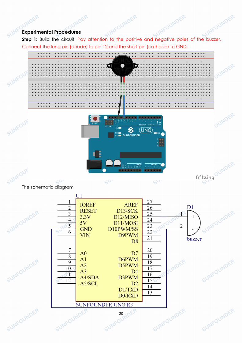
Experimental ProceduresStep 1: Build the circuit. Pay attention to the positive and negative poles of the buzzer.Connect the long pin (anode) to pin 12 and the short pin (cathode) to GND.
The schematic diagram
21
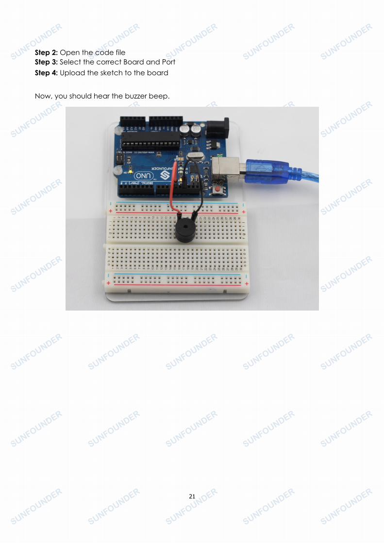
Step 2: Open the code fileStep 3: Select the correct Board and PortStep 4: Upload the sketch to the board
Now, you should hear the buzzer beep.

22
Lesson 4 Photoresistor
IntroductionA photoresistor or photocell is a light-controlled variable resistor. The resistance of aphotoresistor decreases with increasing incident light intensity; in other words, itexhibits photoconductivity. A photoresistor can be applied in light-sensitive detector circuits,and light- and darkness-activated switching circuits.
Components- 1 * SunFounder Uno board- 1 * USB data cable- 1 * Photoresistor- 1 * Resistor (10KΩ)- 8 * LED- 8 * Resistor (220Ω)- Jumper wires-1 * Breadboard
Experimental Principle
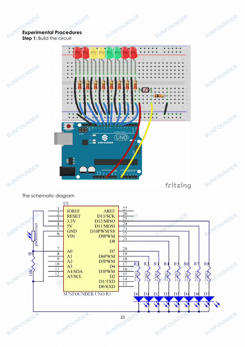
The resistance of a photoresistor changes with incident light intensity. If the light intensitygets higher, the resistance decreases; if it gets lower, the resistance increases.
In this experiment, we will use eight LEDs to show the light intensity. The higher the lightintensity is, the more LEDs will light up. When the light intensity is high enough, all the LEDswill be on. When there is no light, all the LEDs will go out.
23
Experimental ProceduresStep 1: Build the circuit
The schematic diagram
24
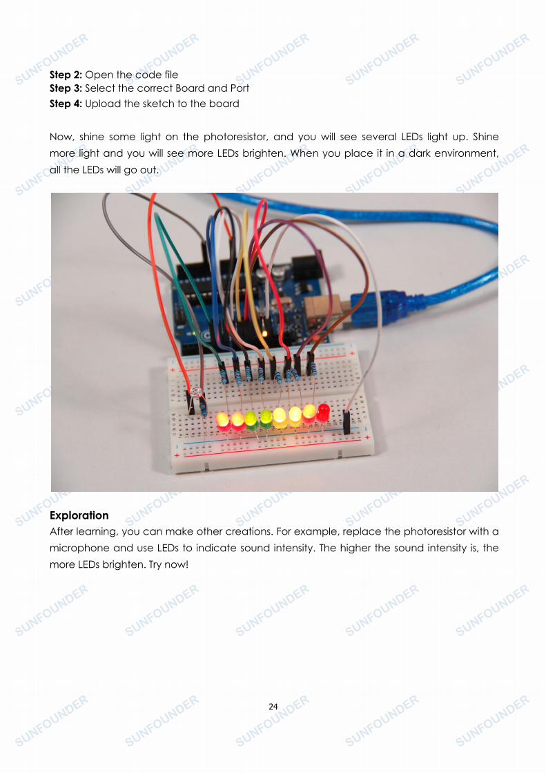
Step 2: Open the code fileStep 3: Select the correct Board and PortStep 4: Upload the sketch to the board
Now, shine some light on the photoresistor, and you will see several LEDs light up. Shinemore light and you will see more LEDs brighten. When you place it in a dark environment,all the LEDs will go out.
ExplorationAfter learning, you can make other creations. For example, replace the photoresistor with amicrophone and use LEDs to indicate sound intensity. The higher the sound intensity is, themore LEDs brighten. Try now!

25
Lesson 5 RGB LED
IntroductionIn this lesson, we will use the PWM technology to control an RGB LED to flash various kinds ofcolors.
Components- 1 * RGB LED- 3 * Resistor (220Ω)- 1 * Breadboard- 1 * SunFounder Uno board- Jumper wires- USB cable
PrincipleRGB
RGB stands for the red, green, and blue color channels and is an industry color standard.RGB displays various new colors by changing the three channels and superimposing them,which, according to statistics, can create 16,777,216 different colors.
Each of the three color channels has 255 stages of brightness. When the three primarycolors are all 0, it is the least bright, thus turning it off. When the three colors are all 255,which is the brightest, the LEDs will brighten. When the light emitted of the three colors aremixed together, the colors will be mixed too. However, the brightness is equal to the sum ofall brightness. And the more you mix, the brighter the LED gets. This process is known asadditive mixing.
PWM
26
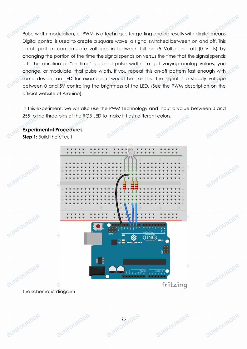
Pulse width modulation, or PWM, is a technique for getting analog results with digital means.Digital control is used to create a square wave, a signal switched between on and off. Thison-off pattern can simulate voltages in between full on (5 Volts) and off (0 Volts) bychanging the portion of the time the signal spends on versus the time that the signal spendsoff. The duration of "on time" is called pulse width. To get varying analog values, youchange, or modulate, that pulse width. If you repeat this on-off pattern fast enough withsome device, an LED for example, it would be like this: the signal is a steady voltagebetween 0 and 5V controlling the brightness of the LED. (See the PWM description on theofficial website of Arduino).
In this experiment, we will also use the PWM technology and input a value between 0 and255 to the three pins of the RGB LED to make it flash different colors.
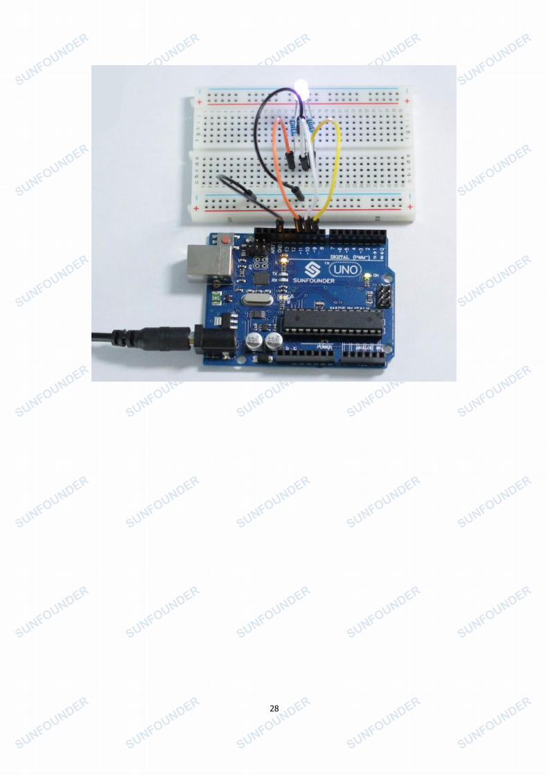
Experimental ProceduresStep 1: Build the circuit
The schematic diagram

27
Step 2: Open the code fileStep 3: Select the correct Board and PortStep 4: Upload the sketch to the board
Here you should see the RGB LED flash circularly red, green, and blue first, then red, orange,yellow, green, blue, indigo, and purple.
28

29
Lesson 6 Relay
IntroductionAs we know relay is a device which is used to provide connection between two or morepoints or device in response to the input signal applied. In another words relay provideisolation between the controller and the device as we know devices may work on AC aswell as on DC. However, they receive signals from microcontroller which works on DChence we require a relay to bridge the gap. Relay is extremely useful when you need tocontrol a large amount of current or voltage with small electrical signal.
Components- 1 * SunFounder Uno board- 1 * USB data cable- 1 * Relay- 1 * LED- 1 * Resistor (220Ω)- 1 * Resistor (1KΩ)- 1 * NPN Transistor- 1 * Diode (Rectifier)- Several jumper wires- 1 * Breadboard
Experimental Principle
Relay
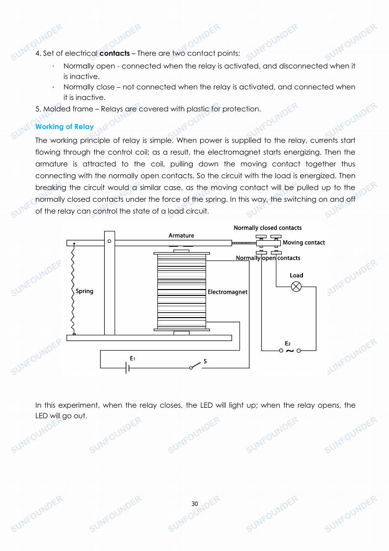
There are 5 parts in every relay:
1. Electromagnet – It consists of an iron core wounded by coil of wires. When electricity ispassed through, it becomes magnetic. Therefore, it is called electromagnet.
2. Armature – The movable magnetic strip is known as armature. When current flowsthrough them, the coil is it energized thus producing a magnetic field which is used tomake or break the normally open (N/O) or normally close (N/C) points. And the armaturecan be moved with direct current (DC) as well as alternating current (AC).
3. Spring – When no currents flow through the coil on the electromagnet, the spring pullsthe armature away so the circuit cannot be completed.
30
4. Set of electrical contacts – There are two contact points:
. Normally open - connected when the relay is activated, and disconnected when itis inactive.
. Normally close – not connected when the relay is activated, and connected whenit is inactive.
5. Molded frame – Relays are covered with plastic for protection.
Working of Relay
The working principle of relay is simple. When power is supplied to the relay, currents startflowing through the control coil; as a result, the electromagnet starts energizing. Then thearmature is attracted to the coil, pulling down the moving contact together thusconnecting with the normally open contacts. So the circuit with the load is energized. Thenbreaking the circuit would a similar case, as the moving contact will be pulled up to thenormally closed contacts under the force of the spring. In this way, the switching on and offof the relay can control the state of a load circuit.
In this experiment, when the relay closes, the LED will light up; when the relay opens, theLED will go out.
31
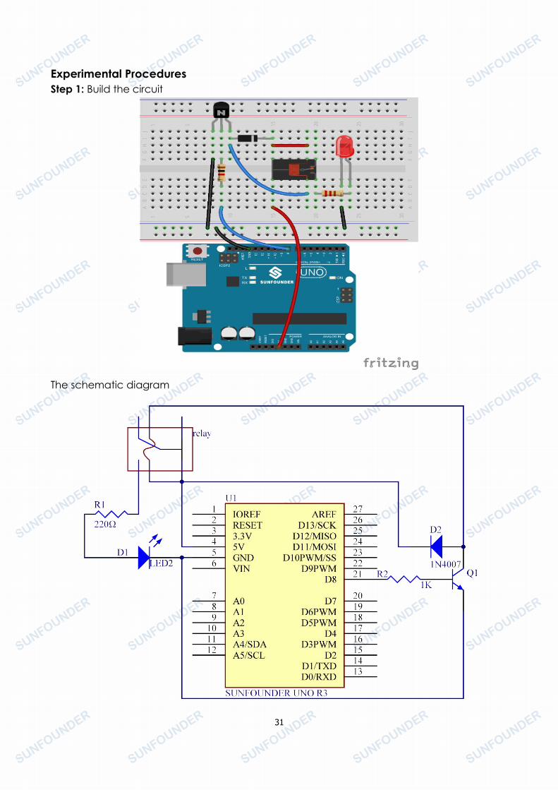
Experimental ProceduresStep 1: Build the circuit
The schematic diagram
32
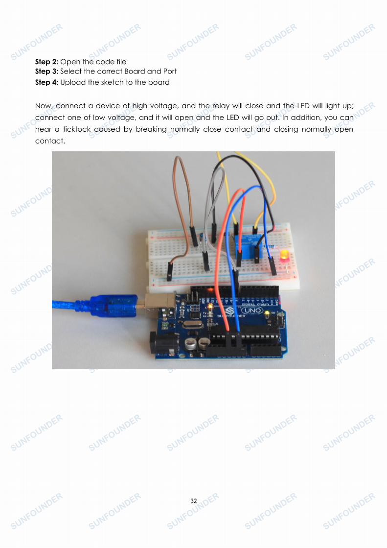
Step 2: Open the code fileStep 3: Select the correct Board and PortStep 4: Upload the sketch to the board
Now, connect a device of high voltage, and the relay will close and the LED will light up;connect one of low voltage, and it will open and the LED will go out. In addition, you canhear a ticktock caused by breaking normally close contact and closing normally opencontact.
33
Lesson 7 Tilt-Switch
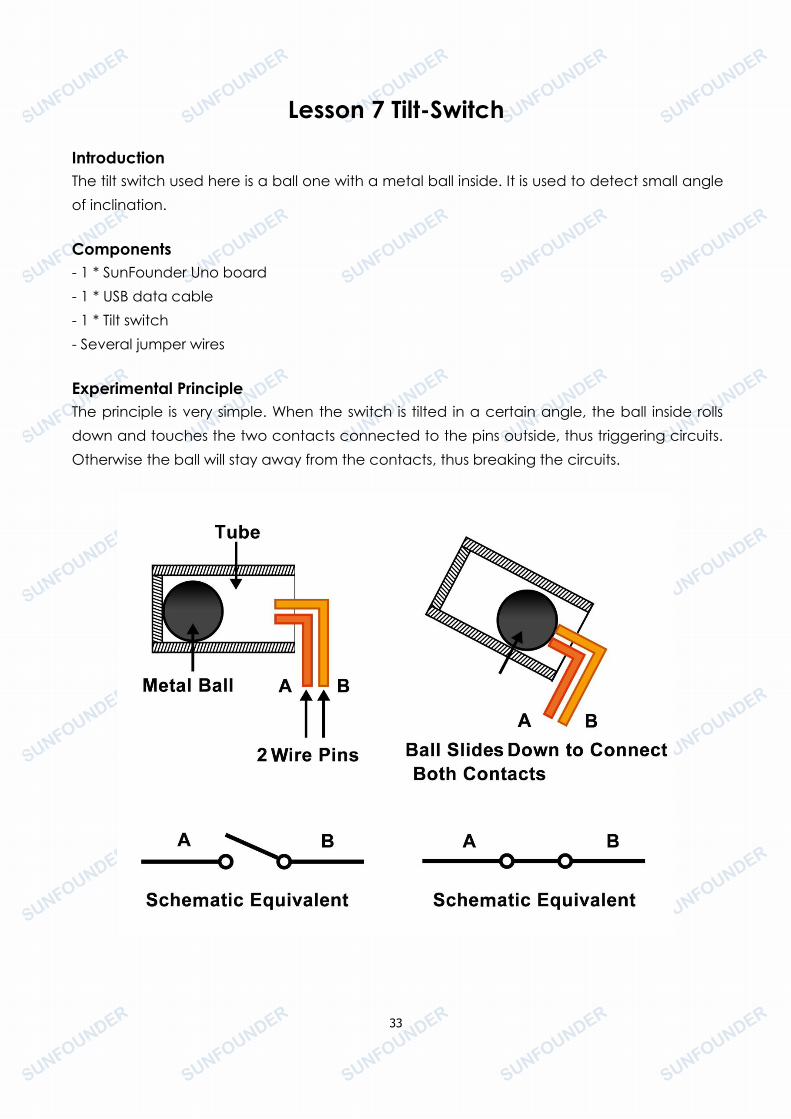
IntroductionThe tilt switch used here is a ball one with a metal ball inside. It is used to detect small angleof inclination.
Components- 1 * SunFounder Uno board- 1 * USB data cable- 1 * Tilt switch- Several jumper wires
Experimental PrincipleThe principle is very simple. When the switch is tilted in a certain angle, the ball inside rollsdown and touches the two contacts connected to the pins outside, thus triggering circuits.Otherwise the ball will stay away from the contacts, thus breaking the circuits.
34
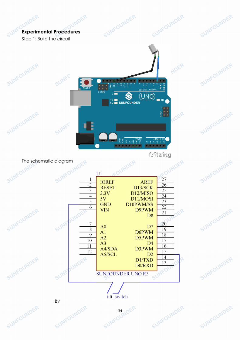
Experimental ProceduresStep 1: Build the circuit
The schematic diagram
Bv
35
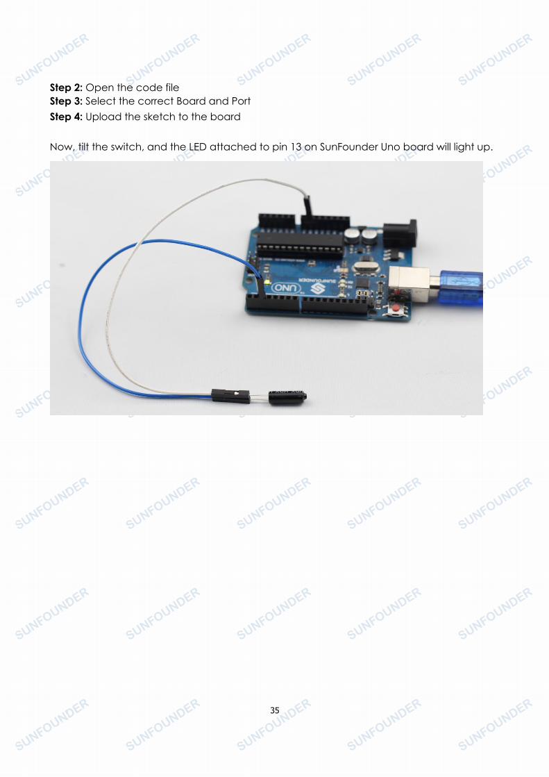
Step 2: Open the code fileStep 3: Select the correct Board and PortStep 4: Upload the sketch to the board
Now, tilt the switch, and the LED attached to pin 13 on SunFounder Uno board will light up.
36
Lesson 8 Servo
IntroductionServo is a type of geared motor that can only rotate 180 degrees. It is controlled by sendingelectrical pulses from your SunFounder board. These pulses tell the servo what position itshould move to.
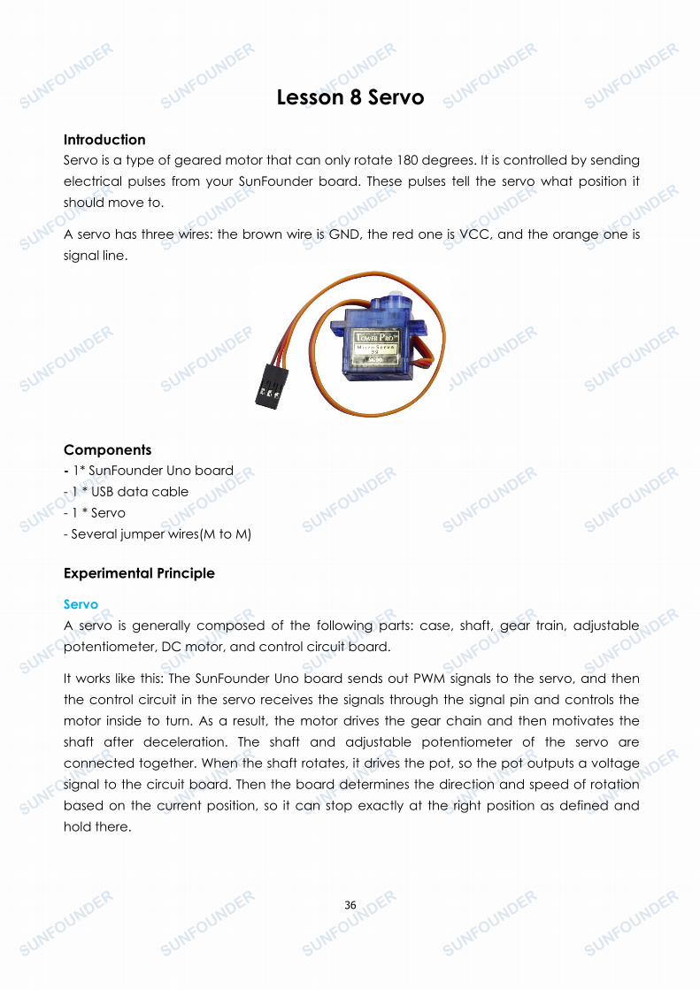
A servo has three wires: the brown wire is GND, the red one is VCC, and the orange one issignal line.
Components- 1* SunFounder Uno board- 1 * USB data cable- 1 * Servo- Several jumper wires(M to M)
Experimental Principle
ServoA servo is generally composed of the following parts: case, shaft, gear train, adjustablepotentiometer, DC motor, and control circuit board.
It works like this: The SunFounder Uno board sends out PWM signals to the servo, and thenthe control circuit in the servo receives the signals through the signal pin and controls themotor inside to turn. As a result, the motor drives the gear chain and then motivates theshaft after deceleration. The shaft and adjustable potentiometer of the servo areconnected together. When the shaft rotates, it drives the pot, so the pot outputs a voltagesignal to the circuit board. Then the board determines the direction and speed of rotationbased on the current position, so it can stop exactly at the right position as defined andhold there.

37
Experimental Procedures
Step 1: Build the circuit (Brown to GND, Red to VCC, Orange to pin 9 of the control board)
The schematic diagram
38
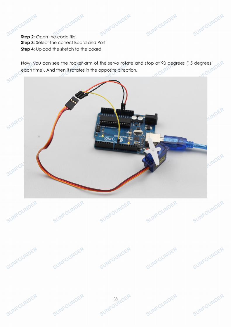
Step 2: Open the code fileStep 3: Select the correct Board and PortStep 4: Upload the sketch to the board
Now, you can see the rocker arm of the servo rotate and stop at 90 degrees (15 degreeseach time). And then it rotates in the opposite direction.
39
Lesson 9 Thermistor
IntroductionA thermistor is a type of resistor whose resistance varies significantly with temperature.
Components- 1*SunFounder Uno board- 1*USB data cable- 1*Thermistor- 1*Resistor (10K)- Several jumper wires
Experimental PrincipleThe resistance of the thermistor varies significantly with ambient temperature. It can detectsurrounding temperature changes in real time. Send the temperature data to analog I/Oport of SunFounder. Next we only need to convert sensor output to Celsius temperature bysimple programming and display it on the Serial Monitor.
Experimental ProceduresStep 1: Build the circuit
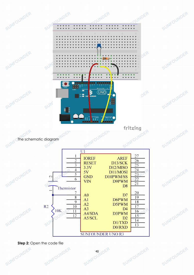
40
The schematic diagram
Step 2: Open the code file
41
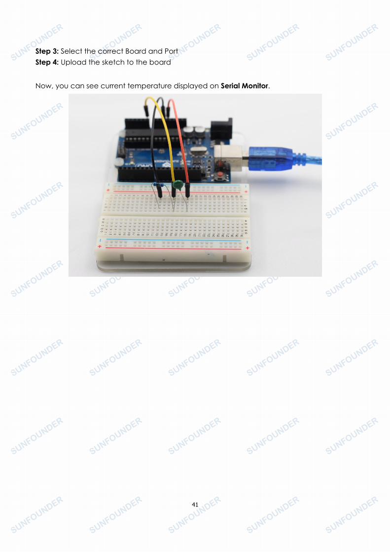
Step 3: Select the correct Board and PortStep 4: Upload the sketch to the board
Now, you can see current temperature displayed on Serial Monitor.
42
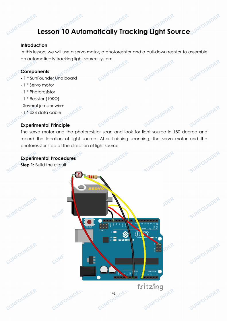
Lesson 10 Automatically Tracking Light Source
IntroductionIn this lesson, we will use a servo motor, a photoresistor and a pull-down resistor to assemblean automatically tracking light source system.
Components- 1 * SunFounder Uno board- 1 * Servo motor- 1 * Photoresistor- 1 * Resistor (10KΩ)- Several jumper wires- 1 * USB data cable
Experimental PrincipleThe servo motor and the photoresistor scan and look for light source in 180 degree andrecord the location of light source. After finishing scanning, the servo motor and thephotoresistor stop at the direction of light source.
Experimental ProceduresStep 1: Build the circuit
43
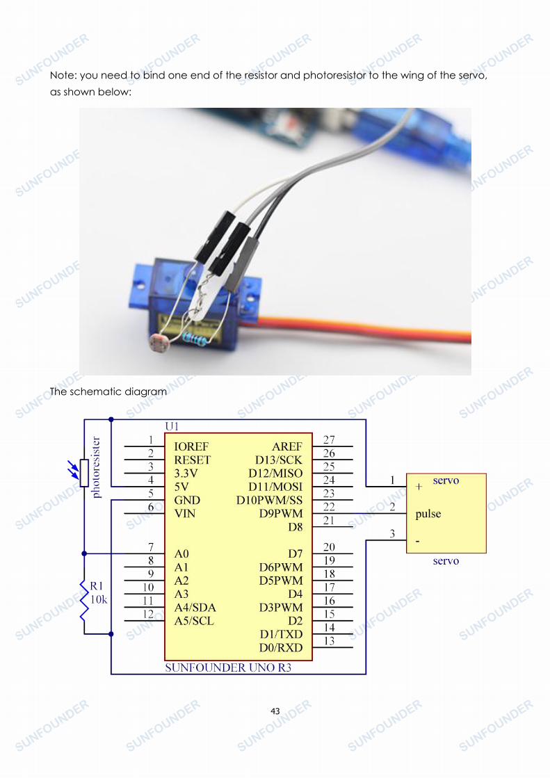
Note: you need to bind one end of the resistor and photoresistor to the wing of the servo,as shown below:
The schematic diagram
44
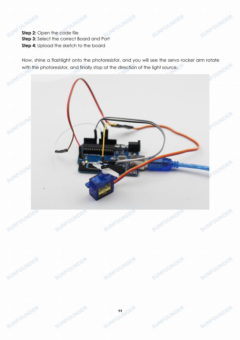
Step 2: Open the code fileStep 3: Select the correct Board and PortStep 4: Upload the sketch to the board
Now, shine a flashlight onto the photoresistor, and you will see the servo rocker arm rotatewith the photoresistor, and finally stop at the direction of the light source.
45
Lesson 11 Light Alarm
IntroductionThis experiment is a very interesting one – a DIY phototransistor. DIY phototransistors use theglow effect and photoelectric effect of LEDs. That is, LEDs will generate weak currents whensome light is shined on it. And we use a transistor to amplify the currents generated, so theSunFounder Uno board can detect them.
Components- 1 * SunFounder Uno board- 1 * Breadboard- 1 * USB cable- Jumper wires- 1 * Active buzzer- 1 * Resistor (10KΩ)- 1 * LED- 1 * NPN Transistor S8050
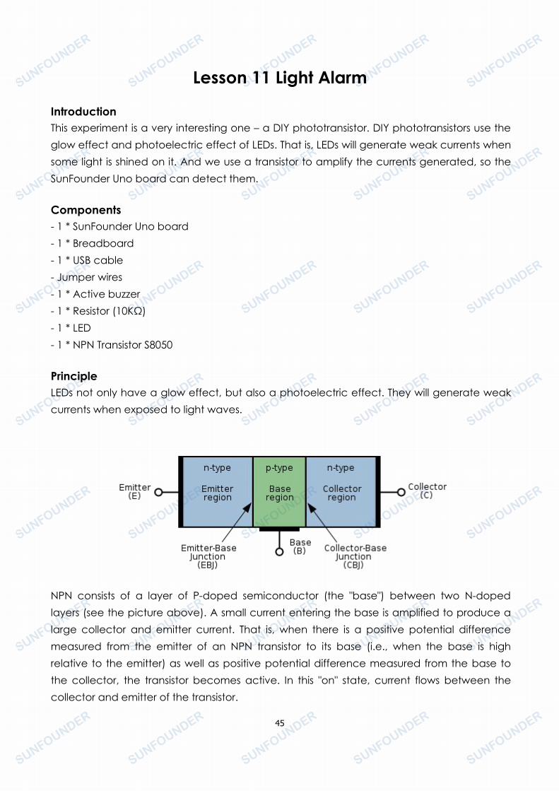
PrincipleLEDs not only have a glow effect, but also a photoelectric effect. They will generate weakcurrents when exposed to light waves.
NPN consists of a layer of P-doped semiconductor (the "base") between two N-dopedlayers (see the picture above). A small current entering the base is amplified to produce alarge collector and emitter current. That is, when there is a positive potential differencemeasured from the emitter of an NPN transistor to its base (i.e., when the base is highrelative to the emitter) as well as positive potential difference measured from the base tothe collector, the transistor becomes active. In this "on" state, current flows between thecollector and emitter of the transistor.
46
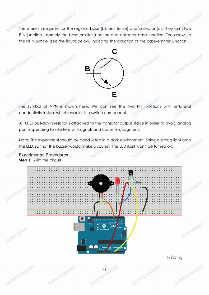
There are three poles for the regions: base (b), emitter (e) and collector (c). They form twoP-N junctions, namely the base-emitter junction and collector-base junction. The arrows inthe NPN symbol (see the figure below) indicates the direction of the base-emitter junction.
The symbol of NPN is shown here. We can see the two PN junctions with unilateralconductivity inside, which enables it a switch component.
A 10kΩ pull-down resistor is attached to the transistor output stage in order to avoid analogport suspending to interfere with signals and cause misjudgment.
Note: This experiment should be conducted in a dark environment. Shine a strong light ontothe LED, so that the buzzer would make a sound. The LED itself won't be turned on.
Experimental ProceduresStep 1: Build the circuit
47
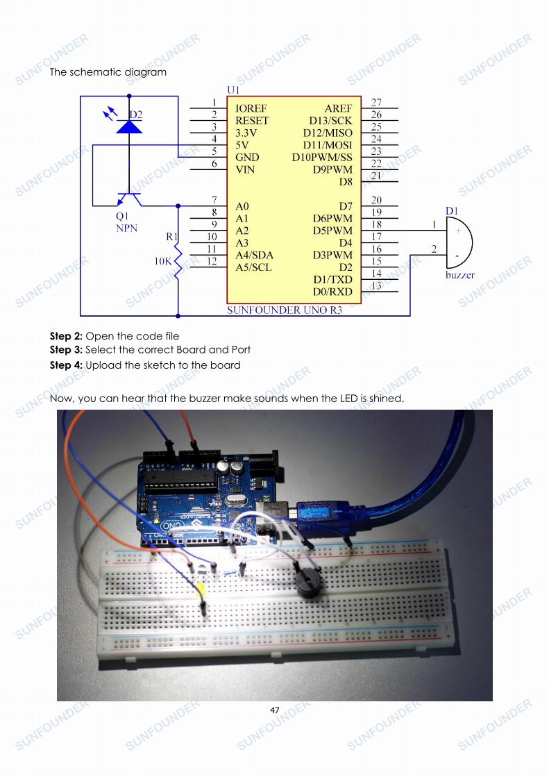
The schematic diagram
Step 2: Open the code fileStep 3: Select the correct Board and PortStep 4: Upload the sketch to the board
Now, you can hear that the buzzer make sounds when the LED is shined.

48
Copyright Notice
All contents including but not limited to texts, images, and code in this manual are owned
by the SunFounder Company. You should only use it for personal study, investigation,
enjoyment, or other non-commercial or nonprofit purposes, under the related regulations
and copyrights laws, without infringing the legal rights of the author and relevant right
holders. For any individual or organization that uses these for commercial profit without
permission, the Company reserves the right to take legal action.