preliminary neutronic and thermal-safety analysis for
TRANSCRIPT

MASTER THESIS, DUAL DIPLOMA PROGRAM ADVANCED LEVEL, 30 ECTS
-STOCKHOLM BEIJING, 2018
Preliminary Neutronic and Thermal-Safety Analysis for CFETR HCCB-TBM
Baorui Zhang
KTHSchool of Science Tsinghua University INET

TRITA-SCI-GRU 2018:064
www.kth.sewww.tsinghua.edu.cn

TSINGHUA UNIVERSITY KTH-ROYAL INSTITUTE OF TECHNOLOGY
Preliminary Neutronic and Thermal-Safety Analysis for
CFETR HCCB-TBM
Baorui Zhang
Thesis Submitted to
Tsinghua University KTH Royal Institute of Technology
In partial fulfilment of the requirement
for the degree of
Master of Science
In
Nuclear Science and Technology
In partial fulfilment of the requirement
for the degree of
Master of Science
In
Engineering Physics
Co-supervisor: Associate professor
Lang Minggang
Co-supervisor: Associate professor
Jan Dufek
Division of Reactor Physics,Thermal
Hydraulics & System Simulation KÄRNENERGITEKNIK
UNDER THE COOPERATION AGREEMENT ON DUAL MASTER’S DEGREE PROGRAM IN NUCLEAR ENERGY RELATED DISCIPLINES
JUNE 2018 (Month Year)

Abstrakt
I
Preliminär Neutronisk och Termisk Säkerhetsanalys för
CFETR HCCB-TBM
För att fullständigt kunna smälta och absorbera designtekniken från den
internationella termonukleära experimentreaktorn (ITER), föreslog Kina officiellt
utvecklingen av Kina Fusion Engineering Test Reactor (CFETR) 2011. Det huvudsakliga
målet med CFETR är att uppnå en 50-200MW lång puls eller steady state-drift, för att
verifiera tritiums självförsörjning, för att utforska fjärroperationsteknik och för att
undersöka det tekniska tillvägagångssättet för att erhålla en fusionstationslicensfil för
reaktornivå. Filt är en av nyckelkomponenterna i CFETR. Huvudfunktionerna i filten är
tritiumproduktion, värmextraktion och strålskärmning, vilket gör att filtdesignen är en av
CFETR: s utmaningar.
Baserat på konceptet med heliumkyld keramikuppfödningsfilt som föreslås av
Southwest Institute of Physics (SWIP) ges en uppdaterad filtdesign med god
tritiumproduktionskapacitet, enkel struktur och relativt lågt tryckfall av kylvätska i denna
avhandling. Med den uppdaterade filtstrukturen utförs den termiska hydrauliska och
säkerhetsanalysen av den typiska filtmodulen, och rationaliteten hos filtens designschema
utvärderas.
Genom utvecklingen av neutronfysikdesign har tritiumproduktionskapaciteten hos
denna filt studerats. I neutronisk design studeras effekterna av pebbelsängstrukturen och
layouten på tritiumuppfödningsförhållandet (TBR), påverkan av filtstrukturen och
materialet på TBR studeras och variationstrenden av tritiumuppfödningsytan hos filten
med olika mönster erhålls. Med den optimerade designen uppnådde den totala TBR 1.17
som kan uppfylla tritiums självförsörjningsmålet (TBR≥1.05). På grundval av detta
erhålles den termiska avsättningsfördelningen av hela filtmodulen och den detaljerade
fördelningen av effektdensiteten hos de olika komponenterna i den typiska filtmodulen
på ekvatorialplanet ges.
På grundval av den erhållna kärnvärmefördelningen av en typisk filtmodul utförs
designen av filtkylstrukturen och termisk hydraulikanalys. Täcken adopterar en 1 × 5
intern design. Kylmediums flödesschema för filten är följande: För det första kommer
kylmediet in i det första väggkylröret från bakplattans hålrum 1 och går sedan in i
bakplattans hålrum 2 för att konvergera efter kylning av den första väggen. Efter att ha

Abstrakt
II
fördelats genom kaviteten 3 kommer kylmediet in i revbenen och de övre och nedre
täckplattorna parallellt. Därefter kommer kylvätskan in i bakplattans hålrum 4 och
fördelas till tritiumuppfödningsenheterna och slutligen strömmar ut ur filten genom
håligheten 5. Genom separat analys av kylrören i varje komponent ökar
temperaturhöjningen och tryckfallet av kylmediet i varje komponent erhålles. Genom
separat analys av komponenterna i filten erhålls de termiska hydrauliska parametrarna för
varje komponent. Det är bevisat att temperaturen hos varje komponent ligger inom
materialets gränstemperatur, och filten uppfyller kraven på termisk design.
Den oavsiktliga säkerhetsanalysen av filtkylsystemet utförs av det generella system
övergångs beteende analys programmet RELAP5. I händelse av en LOCA-olycka i kärlet
kommer kylmedelsröret i första väggen att brista och kylmediet kommer in i
vakuumbehållaren. Trycket i vakuumkärlet uppgick till 23 kPa, vilket är lägre än
konstruktionsstandarden för ITER-vakuumkärlstrukturen (200 kPa). Säkerhetssystemet
för filtsystemet under olyckan kan garanteras.
Nyckelord:HCCB TBM; TBR; Neutronisk studie; Säkerhetsanalys

Abstract
III
Abstract
In order to fully digest and absorb the design technology of the International
Thermonuclear Experimental Reactor (ITER), China officially proposed the development
of China Fusion Engineering Test Reactor (CFETR) in 2011. The main goal of CFETR is
to achieve a 50-200MW long pulse or steady-state operation, to verify the self-sufficiency
of tritium, to explore remote operation technology, and to explore the technical approach
to obtain a demonstration reactor-level fusion station license file. The blanket is one of
the key components of the CFETR. The main functions of the blanket are tritium
production, heat extraction and radiation shielding, which makes the blanket design is
one of the top challenges of CFETR.
Based on the concept of helium-cooled ceramic breeder blanket proposed by
Southwest Institute of Physics (SWIP), an updated blanket design with good tritium
production capability, simple structure and relatively small pressure drop of coolant is
given in this dissertation. With the updated blanket structure, the thermal-hydraulic and
safety analysis of the typical blanket module are performed, and the rationality of the
design scheme of the blanket is evaluated.
Through the development of neutron physics design, the tritium production
capability of this blanket has been studied. In the neutronics design, the effects of the
pebble bed structure and layout on the tritium breeding ratio (TBR), the influence of the
blanket structure design and materials on the TBR are studied, and the variation trend of
the tritium breeding performance of the blanket with different designs is obtained. With
the optimized design, the total TBR reached 1.17, which can meet the tritium self-
sufficiency goal (TBR≥1.05). On the basis of this, the thermal deposition distribution of
the whole blanket module is obtained, and the detailed distribution of the power density
of the various components of the typical blanket module on the equatorial plane is given.
On the basis of the obtained nuclear thermal distribution of a typical blanket module,
the design of the blanket cooling structure and thermal-hydraulics analysis are carried out.
The blanket adopts a 1×5 internal design. The coolant flow scheme of the blanket is as
follows: First, the coolant enters the first wall cooling pipe from the back plate cavity 1,
and then enters the back plate cavity 2 to converge after cooling the first wall. After being
Abstract
IV
distributed through the cavity 3, the coolant enters the ribs and the upper and bottom cover
plates in parallel. Then, the coolant enters the back plate cavity 4 and are distributed to
the tritium breeding units, and finally flow out of the blanket through the cavity 5.
Through the separate analysis of the cooling pipes in each component, the temperature
rise and pressure drop of the coolant in each component are obtained. Through the
separate analysis of the components of the blanket, the thermal-hydraulic parameters of
each component are obtained. It is proved that the temperature of each component is
within the limit temperature of the material, and the blanket meets the thermal design
requirements.
The accidental safety analysis of the blanket cooling system is performed by the
general system transient behavior analysis program, RELAP5. In the case of an in-vessel
LOCA accident, the coolant pipe in first wall will rupture and the coolant enters the
vacuum vessel. The pressure in vacuum vessel reached 23 kPa, which is lower than the
design standard of ITER vacuum vessel structure (200 kPa). The safety of the blanket
system under the accident can be guaranteed.
Key words: HCCB TBM; TBR; Neutronic Study; Safety Analysis

Contents
V
Contents
Chapter 1 Introduction .................................................................................................... 1
1.1 Background .............................................................................................................. 1
1.2 Tokamak concept and blanket module ..................................................................... 4
1.3 Current progress on blanket techniques ................................................................... 6
1.3.1 ITER-TBM ........................................................................................................ 6
1.3.2 CFETR-TBM ..................................................................................................... 9
1.4 Main content of this thesis ..................................................................................... 14
Chapter 2 Methodology & Calculation Codes .......................................................... 16
2.1 Design principles and requirements ....................................................................... 16
2.1.1 Design principles ............................................................................................. 16
2.1.2 Design requirements ........................................................................................ 16
2.2 Neutronics calculation theory and methods ........................................................... 17
2.2.1 Neutron transport theory .................................................................................. 17
2.2.2 Tritium breeding ratio ...................................................................................... 18
2.2.3 Fusion power multiplication factor.................................................................. 19
2.2.4 Calculation code and data library .................................................................... 19
2.3 Activation theory and calculation methods ............................................................ 21
2.3.1 Material activation theory ................................................................................ 21
2.4 Thermal-hydraulic and safety analysis................................................................... 23
2.4.1 Thermal-hydraulic analysis ............................................................................. 23
2.4.2 Safety analysis ................................................................................................. 23
2.5 Summary ................................................................................................................ 26
Chapter 3 Neutronic Study of HCCB-TBM ............................................................... 27
3.1 Material Adoption of CFETR HCCB TBM ........................................................... 27
3.1.1 Structural material ........................................................................................... 27
3.1.2 Tritium breeding material ................................................................................ 28
3.1.3 Neutron multiplication material....................................................................... 28
3.1.4 Plasma facing material (PFM) ......................................................................... 29
3.2 Structural design of CFETR HCCB TBM ............................................................. 30

Contents
VI
3.3 Neutronic model and calculation procedure .......................................................... 32
3.3.1 Neutron wall loading ....................................................................................... 33
3.3.2 Tritium breeding ratio (TBR) .......................................................................... 34
3.3.3 Optimization design for tritium breeding ........................................................ 35
3.4 Heat deposition distribution ................................................................................... 39
3.5 Summary ................................................................................................................ 40
Chapter 4 Thermal Hydraulic Analysis of HCCB-TBM ............................................ 41
4.1 Coolant flow scheme in TBM ................................................................................ 41
4.2 Coolant channel design in each component ........................................................... 42
4.2.1 First wall .......................................................................................................... 42
4.2.2 Caps and Stiff grid ........................................................................................... 43
4.2.3 Cooling plate ................................................................................................... 44
4.3 Thermal hydraulic analysis .................................................................................... 45
4.3.1 Thermal property of materials ......................................................................... 45
4.3.2 Coolant distribution scheme ............................................................................ 47
4.3.3 Coolant pressure drop in each component ....................................................... 48
4.3.4 Helium cooling system .................................................................................... 51
4.3.5 Nodalization of HCS in RELAP5 .................................................................... 54
4.4 Summary ................................................................................................................ 60
Chapter 5 Accident Analysis of HCCB-TBM ............................................................. 61
5.1 Safety function of blanket system .......................................................................... 61
5.2 Accident analysis.................................................................................................... 63
5.2.1 Postulated Initiator Events (PIEs) ................................................................... 63
5.2.2 In-vessel LOCA ............................................................................................... 65
5.3 Summary ................................................................................................................ 68
Chapter 6 Summary and Conclusions ....................................................................... 69
References ..................................................................................................................... 70
Acknowledgements ...................................................................................................... 75
Resume ..76........................................................................................................................

Chapter 1 Introduction
1
Chapter 1 Introduction
1.1 Background
With the characteristic of inexhaustible fuel supplication, high efficiency energy
production and cleanliness, nuclear fusion is expected to be one of the fundamental ways
to hopefully completely solve the energy problem for human society. Some of the primary
fusion reactions that exist in nature are listed as follows:
2 2 3 1
2 2 3
2 3 4
4.0 (50%)
3.3 (50%)
17.6
D D H H H H MeV
D D H H H n MeV
D T H H H n MeV
(1-1)
For two or more light atomic nuclei can come close enough to form one or more
different atomic nuclei, a substantial energy barrier must be overcome because of
electrostatic repulse forces. The Lawson criterion, first derived on fusion reactors by John
D. Lawson in 1955 and published in 1957, is an important general measure of a system
that defines the conditions needed for a fusion reactor to reach ignition which is
formulated as follows[1]:
ch lossfE P (1-2)
That means fusion heating exceeds the energy losses where Ech is the energy of
charged fusion products, term f is volume rate (reactions per volume per time).
1 2f n n (1-3)
Where term n1 and n2 represent number density of two reactant nuclei σ, so-called
reaction cross section, means the probability of a reaction to occur as a function of the
relative velocity of reactant nuclei. v is the relative velocity, <> denotes an average over
the Maxwellian velocity distribution at the temperature T.
Plasma clouds lose energy through conduction and radiation. The Lawson criterion
argues that a machine holding a thermalized and quasi-neutral plasma has to meet basic
criteria to overcome radiation losses, conduction losses and reach efficiency of 30 percent.
This became known as the "triple product": the plasma density n, temperature τ and

Chapter 1 Introduction
2
confinement time T. Given the current status of human technology attention has been
focused on attempting to achieve lager plasma density and longer confinement time in
order to get lower temperature.
Figure 1-1 shows fusion cross section as a function of center-of-mass kinetic energy
where D-T fusion reaction has the highest cross section at relatively low temperatures.
Therefore, it is considered to be the most promising candidate for fusion that can be
exploited by human society. Decades of years have been taken to achieve controlled
fusion, but the fact is that to get meaningful reaction rate the temperatures should in the
range of 10-100 KeV, which means the fusion reaction actually exist in plasma state
because the temperatures are well above typical ionization energies (13.6 eV in the
hydrogen case). This is extremely difficult to overcome as it is hard to maintain the plasma
in stable state. Several approaches are developed to achieve long confinement time,
among which magnetic confinement (MCF) and inertial confinement (ICF) are
considered to be two promising methods to achieve fusion. Other concepts such as the Z-
pinch, bubble fusion, electrostatic confinement fusion (ECF), muoncatalysed fusion and
reversed field pinch have been studied but are in the very early stages of development
when compared to ICF and MCF[2].
Figure 1-1 Fusion cross section[3]

Chapter 1 Introduction
3
For Magnetic confinement:
a) Tokamak: the most well-developed and well-funded approach to fusion energy.
This method races hot plasma around in a magnetically confined, donut-shaped
ring, with an internal current. As of April 2012 an estimated 215 experimental
tokamaks were either planned, decommissioned or currently operating (35)
worldwide.
b) Stellarator: Twisted rings of hot plasma. The stellarator attempts to create a natural
twist plasma path, using external magnets, while tokamaks create those magnetic
fields using an internal current. Stellarators were developed by Lyman Spitzer in
1950 and have four designs: Torsatron, Heliotron, Heliac and Helias. One example
is Wendelstein 7-X, a German fusion device that produced its first plasma on
December 10, 2015. It is the world's largest stellarator, designed to investigate the
suitability of this type of device for a power station.
For Inertial confinement:
a) Direct drive: In this technique, lasers directly blast a pellet of fuel. The goal is to
ignite a fusion chain reaction. Ignition was first suggested by John Nuckolls, in
1972[4]. Notable direct drive experiments have been conducted at the Laboratory
for Laser Energetics, Laser Mégajouleand the GEKKO XII facilities. Good
implosions require fuel pellets with close to a perfect shape in order to generate a
symmetrical inward shock wave that produces the high-density plasma.
b) Indirect drive: In this technique, lasers blasts a structure around the pellet of fuel.
This structure is known as a Hohlraum. As it disintegrates the pellet is bathed in a
more uniform x-ray light, creating better compression. The largest system using
this method is the National Ignition Facility.
Table 1-1: Orders of T, n, P and τ for ICF and MCF plasma states
Confinement T(KeV) n(cm-3) P(bar) τ
ICF 100 1026 1012 10-11
MCF 10 1014 10 105
From Table 1-1 it can be concluded that the operation of ICF and MCF differ
significantly in terms of these four physical parameters. The temperature of ICF and MCF
varies in an order of magnitude, and unlike ICF confinement which operates in a pulsed
process, MCF confinement is likely to be steady state. In this thesis the neurotic and safety

Chapter 1 Introduction
4
analysis are based on the MCF (tokamak concept), whose relevant concepts will be
described in greater detail in the following chapters.
1.2 Tokamak concept and blanket module
Tokamaks were invented in the 1950s by Soviet physicists Igor Tamm and Andrei
Sakharov, inspired by an original idea of Oleg Lavrentiev[5]. It is the most well-developed
and well-funded approach to fusion energy. For a typical tokamak fusion reactor, it is
mainly composed of the following components or systems: 1) core plasma; 2) plasma
support system (superconducting magnet, plasma heating and driving system, charging
system); 3) fusion reactor core.
Figure 1-2 Cross section view of ITER
The fusion reactor core includes: first wall, blanket module, the divertor, radiation
shielding blocks, vacuum vessel and the biological shielding, etc. The blanket is a
component that surrounds the fusion reactor and it is the key component to ensure energy
transformation and tritium production. The main functions of blanket is listed as follows:
a) Tritium production: for D-T reaction to be exploited, the first fuel, deuterium,

Chapter 1 Introduction
5
accounts for 0.014% of all hydrogen contained in seawater, therefore it is almost
inexhaustible considering the seawater supply on earth. However, the second fuel,
tritium is scarce in nature, which makes it necessary to produce tritium on-site for
fusion power being a credible power supply for human society. The promising
pathway to produce tritium is lithium blanket concept via the 6Li(n; α)3H and 7Li(n;
n+α)3H reactions.
6 4i (thermal neutron) 4.8L n T He MeV (1-4)
7 4i (fast neutron) 2.47L n T n He MeV (1-5)
The two main naturally exist isotopes of lithium are 6Li and 7Li. Their corresponding
abundances are 7.7% and 92.2% respectively. However, the 6Li induced tritium
production reaction is the dominant reaction due to its higher cross section at low
neutron energies which can be seen from Figure 1-3.
Figure 1-3 Tritium production cross section of 6Li and 7Li
b) Heat extraction: kinetic energy of neutrons which are generated from fusion
reaction will be transformed to heat deposition in blanket module, which is carried
away by blanket coolant to generate electric power.
c) Radiation shielding: fusion reactor workers will face lethal neutron dose if the
neutron flux produced in the plasma was not shielded in a proper way. The blanket
module works as an indirect shielding component as neutrons will be moderated and

Chapter 1 Introduction
6
eventually absorbed in blanket.
1.3 Current progress on blanket techniques
Great progress has been made in the development of blanket technology at home and
abroad. Dozens of blanket concepts have been proposed which can be roughly divided
into two types according to the forms of the internal tritium-breeding material, namely,
solid breeder blanket and liquid breeder blanket. Tritium breeding material adapted in
solid blanket including Li4SiO4, Li2TiO3, Li2ZrO3, LiAlO2 and Li2O; Beryllium is the
most widely used for neutron multiplication; helium and water are two promising
candidates for coolant of solid blanket; structure material includes reduced activation
ferritic martensitic, Vanadium alloy and SiC, etc. the structure material of liquid blanket
is almost the same as solid blanket, tritium breeding material includes LiPb, liquid lithium
and Flibe, etc. coolant candidates include helium, water and liquid metal (i.e. liquid
tritium breeding material)
Compared with liquid blanket, helium cooled solid breeder blanket is highly likely
to be adapted in the future fusion demonstration (DEMO) power plant. As compared to
liquid metal, adapting helium as coolant can avoid the magneto hydrodynamic (MHD)
effects. Liquid metal is likely to interact with structure material which may raise corrosion
concern is another negative contribution to liquid blanket to be applied. Current progress
on blanket techniques is described in greater detail in the following chapters.
1.3.1 ITER-TBM
ITER (International Thermonuclear Experimental Reactor) is an international
nuclear fusion research and engineering megaproject, which will be the world's largest
magnetic confinement plasma physics experiment. It is an experimental tokamak nuclear
fusion reactor that is being built next to the Cadarache facility in Saint-Paul-lès-Durance,
in Provence, southern France[6].
ITER's mission is to demonstrate the feasibility of fusion power, and prove that it
can work without negative impact. Specifically, the project aims to:
a) Momentarily produce ten times more thermal energy from fusion heating than is
supplied by auxiliary heating (a Q value equals 10).
b) Produce a steady-state plasma with a Q value greater than 5. (Q = 1 is breakeven.)
c) Maintain a fusion pulse for up to 8 minutes.

Chapter 1 Introduction
7
d) Ignite a "burning" (self-sustaining) plasma.
e) Develop technologies and processes needed for a fusion power station —
including superconducting magnets and remote handling (maintenance by robot).
f) Verify tritium breeding concepts.
g) Refine neutron shield/heat conversion technology (most of the energy in the D+T
fusion reaction is released in the form of fast neutrons).
The fact is that ITER is designed to produce a fusion plasma only, which means the
heat generated in reactor will be vented to the atmosphere instead of producing electric
power. To verify blanket techniques ITER currently provides three ports to test different
blanket concepts.
As ITER is funded and run by seven entities: The European Union, India, Japan,
China, Russia, South Korea, and the United States, each entity can propose their own
blanket concept, technology R&D and experiment scheme based on the ITER roadmap.
Proposed test blanket modules (TBM) concepts are listed in Table 1-2.
Table 1-2 TBM concepts proposed by ITER members
Nation EU Russia Japan U.S.A Korea India China
TBM HCPB CHC WCCB HCSB HCSB LLCB HCSB
Tritium
breeding
material
Li4SiO4 Li4SiO4 Li2TiO3 Li4SiO4 Li4SiO4 LiPb Li4SiO4
Neutron
multiplication
material
Be Be Be Be Be - Be
Structure
material EUROFER RAFM F82H F82H RAFM LAFMS CLF-1
Coolant He He H2O He He He He
Operation
pressure
[MPa]
8 8 15.5 8 8 1.2 8
Inlet/outlet
temperature
[°C]
300/500 300/500 280/325 300/500 300/500 350/460 300/500

Chapter 1 Introduction
8
Figure 1-4 Ports for TBMs in ITER
Based on the current progress of each TBM, six different test blanket modules will
be tested within ITER: HCPB (helium cooled pebble bed) and HCLL (helium cooled
lithium lead) of EU, WCCB (water cooled ceramic breeder) of Japan, HCCR (helium
cooled ceramic reflector) of South Korea, HCCB (helium cooled ceramic breeder) of
China and LLCB (lead lithium ceramic breeder) of India. Associated structure design of
each TBM are listed as Figure 1-5 ~ Figure 1-10.
Figure 1-5 EU HCPB TBM[7] Figure 1-6 EU HCLL TBM[8]

Chapter 1 Introduction
9
Figure 1-7 Japan WCCB TBM[9] Figure 1-8 Korea HCCR TBM[10]
Figure 1-9 China HCCB TBM[11] Figure 1-10 India LLCB TBM[12]
1.3.2 CFETR-TBM
The fact that the real burning time during 14 years of D-T operation is only about 4%
results in:
a) There is no enough fusion energy produced for utilization.
b) The total neutron flux is not enough to demonstrate the tritium is self-sustainable.

Chapter 1 Introduction
10
c) No enough neutrons to do the material tests in high flux fusion neutron radioactive
environments.
Therefore, the construction of a fusion demonstration reaction still has a long way
to go as the research of ITER is mainly on physics, not the real fusion energy generation,
which leads the necessity of an engineering test reactor to bridge the gaps between ITER
and DEMO.
In order to fully digest and absorb the ITER design technology, to master the relevant
physics and engineering design and key technologies of the fusion reactor, and to carry
out the overall design research of China's magnetic confinement fusion reactor, China
established the overall design group (preparation) of the magnetic confinement fusion
reactor and formally proposed the development plan of China Fusion Engineering Test
Reactor (CFETR) in 2011.
Figure 1-11 Cross section view of CFETR
The mission and design goal of CFETR are[13]:
a) A good complement to ITER;
b) Relay on the existing ITER physical and technical bases;
c) Fusion power Pf = 50~200MW;
d) Steady-state or long pulse operation (duty cycle ≥ 0.3- 0.5);
e) Demonstration of full cycle of T self-sustained;
f) Exploring options for DEMO blanket & divertor with an easily changeable
capability by remote handling.

Chapter 1 Introduction
11
Figure 1-12 Superconducting magnet scheme Figure 1-13 Water-cooled copper magnet scheme
Currently two design versions are under consideration based on the physical limits
and technical availability: superconducting magnet scheme and water-cooled copper
magnet scheme. Figure 1-12 and Figure 1-13 roughly show the size of these two versions
of CFETR. Key parameters are listed in Table 1-3.
Table 1-3 Main parameters of two CFETR magnet schemes
Physical Parameters Superconducting Magnet
Water-Cooled Copper
Magnet
Scheme 1 Scheme 2
Fusion Power [MW] 200 115 200
Major Radius 5.7 3.7 3.7
Minor Radius 1.6 1.2 1.2
Elongation Ratio 1.8-2.0 2.0-2.2 2.0-2.2
Triangle Ratio 0.4-0.8 0.6-0.8 0.6-0.8
Plasma Current [MA] 8-10 9.0 8.5
Magnetic Field Strength [T] 4.5-5 4-4.5 4-4.5
NWL [MW/m2] ~0.5 0.32 0.56
As a key component in tokamak confinement fusion reactor, the design of blanket is
one of the most challenging missions of CFETR. In the design of CFETR blanket, more
explorations and trials are needed in materials technology, neutronics design, structural

Chapter 1 Introduction
12
design and thermal-hydraulic design, in order to increase the tritium production ability as
much as possible of the blanket; Considering factors including the reliability of the
blanket, remote maintenance methods, and remote operation technologies, the influence
of the blanket on the operating factors of the fusion reactor should be minimized; a
reasonable distribution of the narrow blanket space is needed. On one hand, there should
be enough space for tritium production, and on the other hand, it is necessary to ensure
that there is enough shielding space left to meet the shielding requirements.
Main considerations of blanket design in CFETR are listed as follows:
a) The blanket should have high efficiency tritium production performance to verify
that the reactor is tritium self-sustained.
b) The blanket should have high availability so that duty cycle of CFETR is larger
than 0.3~0.5 considering the maintenance time.
c) Considering the thickness of shilling blocks, the thickness of inboard and outboard
blanket should no more than 0.7m and 1.2m, respectively.
d) The blanket should be easy to be installed and replaced by remote handling.
Three concepts are proposed by independent institutes which are: The water-cooled
blanket concept[14] (Institute of Plasma Physics, Chinese Academy of Sciences); the
helium-cooled solid blanket[13] (Southwest Institute of Physics), and the liquid lithium
lead blanket [15](Institute of Nuclear Energy Safety of the Chinese Academy of Sciences).
a) Helium Cooled Ceramic Blanket-TBM
Figure 1-14 CFETR HCCB TBM
The concept is mainly based on the design of ITER-TBM, U-type tritium breeding
Chapter 1 Introduction
13
unit structure (as shown in Figure 1-14) and Helium is adopted as coolant with operation
pressure of 8 MPa, Li4SiO4 pebble bed is chosen as tritium breeding material, Be pebble
bed is selected as neutron multiplication material, and structural material is low activation
martensitic steel (RAFM). Some preliminary design and analysis have been conducted.
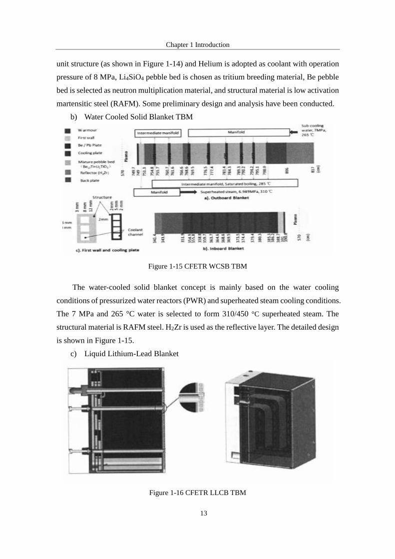
b) Water Cooled Solid Blanket TBM
Figure 1-15 CFETR WCSB TBM
The water-cooled solid blanket concept is mainly based on the water cooling
conditions of pressurized water reactors (PWR) and superheated steam cooling conditions.
The 7 MPa and 265 °C water is selected to form 310/450 °C superheated steam. The
structural material is RAFM steel. H2Zr is used as the reflective layer. The detailed design
is shown in Figure 1-15.
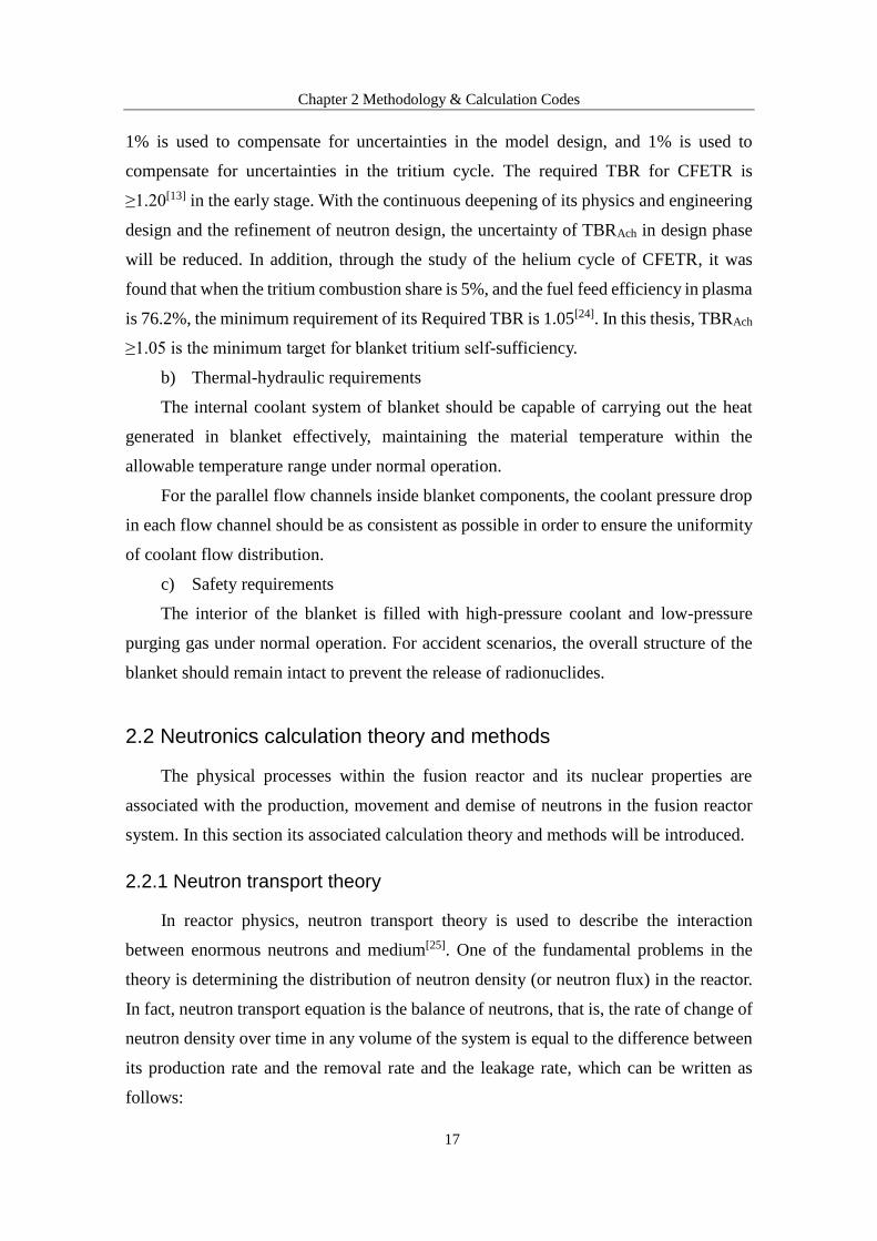
c) Liquid Lithium-Lead Blanket
Figure 1-16 CFETR LLCB TBM

Chapter 1 Introduction
14
The tritium breeding material for this concept is liquid PbLi, structural material is
low activation CLAM steel. It can work under either single cooled mode of 8 MPa Helium
or dual-cooled mode of 8 MPa He and Pb, its detailed configuration is shown in Figure
1-16.
1.4 Main content of this thesis
In this thesis, neutronic study, thermal-hydraulic and safety analysis for a helium
cooled ceramic breeder (HCCB) blanket concept, which was proposed by Southwest
Institute of Physics (SWIP) for CFETR, are performed to evaluate its tritium breeding
capability, thermal-hydraulic property and safety.
Chapter 1, as the introduction part of this dissertation, research background of fusion
and its relevant concepts are described, including the role and classification of blanket
module, main missions and design parameters of ITER and CFETR. Research status of
ITER-TBM and CFETR-TBM are also investigated. The main research contents and
significance of this paper are given, too.
In chapter 2, the design principle and requirements of CFETR-TBM are given in
section 1, including tritium breeding capability, thermal-hydraulic requirements and
safety evaluation. The second section introduces the neutron-related transport theory,
mainly focused on the tritium breeding ratio and heat generation calculation methods.
Activation theory and decay heat evaluation are given in the third part. Thermal-hydraulic
and safety analysis methodology are discussed in the last part.
In chapter 3, the structural design of a helium cooled ceramic breeder blanket
proposed by Southwest Institute of Physics (SWIP) for CFETR was given in details, and
neutronic study was performed by Monto Carlo transport code MCNP. The optimization
for tritium breeding ratio was investigated to meet the tritium self-sufficiency requirement.
Other neutronic parameters including neutron wall loading and heat distribution in
blanket were also given in this chapter.
In chapter 4, based on the heat distribution given in chapter 3, thermal-hydraulic
analysis is performed for typical blanket module. Coolant flow scheme is given in first
section. Coolant temperature rise and pressure drop in each component are obtained, the
helium cooling system model is established with RELAP5, and the results show that
maximum temperature of each material is within the design limits.
In chapter 5, accident analysis is carried out for blanket module under typical

Chapter 1 Introduction
15
accident scenarios based on the failure module and effect analysis methodology. Transient
behavior of blanket module is investigated in RELAP5, and the safety of vacuum vessel
can be ensured in In-Vessel LOCA.

Chapter 2 Methodology & Calculation Codes
16
Chapter 2 Methodology & Calculation Codes
Blanket is the key component to ensure energy transformation and tritium production.
Design requirements that should be satisfied for blanket design are given in this chapter,
along with the detailed description of some theory and calculation methods.
2.1 Design principles and requirements
2.1.1 Design principles
Blanket is the key component for thermal-electricity conversion in fusion reactors.
Considering the complex physical properties and severe operating conditions in fusion
reactor, the design of blanket must follow the basic principles of safety, stability,
reliability, maintainability, etc.
2.1.2 Design requirements
a) Tritium self-sufficiency
Tritium production in fusion reactor mainly depend on the interaction between
neutron and lithium-containing materials. The average number of tritium generated in
blanket by neutron (with averaged energy of 14.1 MeV produced by the D-T reaction in
fusion plasma) and lithium-containing material is generally defined as Achieved Tritium
Breeding Ratio (TBRAch), which represents the tritium breeding capability of a blanket.
Required TBR (TBRReq), however, is the minimum TBR for a fusion reactor to be tritium
self-sufficiency. In an ideal state, the fusion reactor is considered to be tritium self-
sustained when TBRAch is slightly larger than the tritium consumed in fusion plasma, i.e.,
TBRAch >1. However, taking into account the infiltration, decay of the tritium and the
influence of structural materials on TBR[16-20], the tritium self-sufficiency is one of the
top challenges in the design of blanket.
For EU’s DEMO blanket, the TBRAch is set to ≥1.10[21, 22], where 5% of the design
margin is used to compensate for the losses caused by the tritium cycle, the nuclear
database uncertainty, and the fuel burnup process. The other 5% is used to compensate
for the TBR considering the window effect. For America the requirement for TBRAch is
≥1.05[23], 3% of which is used to compensate for the uncertainty in the nuclear database,
Chapter 2 Methodology & Calculation Codes
17
1% is used to compensate for uncertainties in the model design, and 1% is used to
compensate for uncertainties in the tritium cycle. The required TBR for CFETR is
≥1.20[13] in the early stage. With the continuous deepening of its physics and engineering
design and the refinement of neutron design, the uncertainty of TBRAch in design phase
will be reduced. In addition, through the study of the helium cycle of CFETR, it was
found that when the tritium combustion share is 5%, and the fuel feed efficiency in plasma
is 76.2%, the minimum requirement of its Required TBR is 1.05[24]. In this thesis, TBRAch
≥1.05 is the minimum target for blanket tritium self-sufficiency.
b) Thermal-hydraulic requirements
The internal coolant system of blanket should be capable of carrying out the heat
generated in blanket effectively, maintaining the material temperature within the
allowable temperature range under normal operation.
For the parallel flow channels inside blanket components, the coolant pressure drop
in each flow channel should be as consistent as possible in order to ensure the uniformity
of coolant flow distribution.
c) Safety requirements
The interior of the blanket is filled with high-pressure coolant and low-pressure
purging gas under normal operation. For accident scenarios, the overall structure of the
blanket should remain intact to prevent the release of radionuclides.
2.2 Neutronics calculation theory and methods
The physical processes within the fusion reactor and its nuclear properties are
associated with the production, movement and demise of neutrons in the fusion reactor
system. In this section its associated calculation theory and methods will be introduced.
2.2.1 Neutron transport theory
In reactor physics, neutron transport theory is used to describe the interaction
between enormous neutrons and medium[25]. One of the fundamental problems in the
theory is determining the distribution of neutron density (or neutron flux) in the reactor.
In fact, neutron transport equation is the balance of neutrons, that is, the rate of change of
neutron density over time in any volume of the system is equal to the difference between
its production rate and the removal rate and the leakage rate, which can be written as
follows:

Chapter 2 Methodology & Calculation Codes
18
(production rate) (leakage rate) (removal rate)
nQ L R
t
(2-1)
From equation 2-1 we can derive equation 2-2 in the volume element of phase space
(𝑟, E, Ω⃑⃑⃑) at time t:
' ' ' ' '
1( , )
( , , ' ) ( , , , ) ( , , , )
t
s
r Ev t
r E E r E t dE d S r E t
(2-2)
The first term represents the times rate of change of neutrons in the system, one has
𝜕𝛷/𝜕𝑡 = 0 when the system reaches steady state. The second term describes the leakage
rate of neutron. The third term is the neutron removal rate due to medium absorption or
scattering. The right hand side of the equation is total production rate of neutron,
including neutron scattering and external neutron source term S.
2.2.2 Tritium breeding ratio
Tritium breeding ratio is an important physical parameter for the design of fusion
reactor. As described in chapter one, tritium production in fusion reactor mainly depend
on the interaction between neutron and lithium-containing materials (such as Li4SiO4,
Li2TiO3, PbLi) by equation 1-4 and 1-5. Thus tritium breeding ratio (TBR) can be
obtained by equation 2-3 to 2-5:
6 7
n
T TTBR
S
(2-3)
( , )6 6 6 ( , ) ( , , )
Li Li nT N r E r E t dEdr
(2-4)
( , )7 7 7 ( , ) ( , , )Li Li n
T N r E r E t dEdr
(2-5)
Equation 2-4 and 2-5 represent tritium reaction rate of 6Li and 7Li in tritium breeder
material respectively, term Sn is fusion neutron source. When tritium reaction rates are
obtained, the average number of tritium atoms multiplied by the 14.1 MeV fusion neutron
produced by one D-T reaction in plasma can be obtained, i.e. tritium breeding ratio (TBR).
Chapter 2 Methodology & Calculation Codes
19
Total tritium production in fusion reactor can also be derived from equation 2-3:
n T
T
A
S A TBRR dt
N
(2-6)
Where term AT is the atomic weight of tritium, NA represents Avogadro constant.
After determining the tritium production rate, the amount of tritium produced at a given
time in a fusion reactor can be obtained by integrating its value over time.
2.2.3 Fusion power multiplication factor
Heat deposition and power density are important parameters of interest for fusion
reactor design, also they lay the foundation for thermal safety analysis. The application
of fusion energy is mainly achieved by energy generation and amplification in blanket.
The definition of fusion power multiplication factor is the ratio of the power deposition
of all components in fusion reactor to the source neutron power[26]. It is formulated as
follows:
0.8
i ii i
n fusion
P PM
P P
(2-7)
Where term Pi represents the power deposition in the ith component, while term Pn
is the power of neutron source of fusion reactor. Considering that 1/5 of fusion power is
generally consumed to maintain α particle self-heating in plasma[27], the actual core
neutron power entering the blanket is only 4/5 of fusion power, i.e. Pn=4/5Pfusion.
The power deposition on the ith component can be obtained by equation 2-8:
( , ) ( , , )j j j j ij
P E N r E r E t dEdr (2-8)
The integral term in the above equation represents the reaction rate of J material and
neutron in the I component. Term Ej is the energy deposition of one collision of J material
with neutron. Power deposition on ith component is obtained by summarizing energy
deposition on all materials in component i.
2.2.4 Calculation code and data library
The essence of transport calculation lies in solving the neutron flux density in
equation 2-2. The neutron transport equation is a partial differential equation containing

Chapter 2 Methodology & Calculation Codes
20
six variables – spatial variable 𝑟(𝑥, 𝑦, 𝑧); energy variable E; angular variable Ω⃑⃑⃑(θ, φ).
In addition to this, the change of cross section of relevant material in fusion system with
time and space is very complicated. As a result, it is extremely difficult to solve this
equation accurately. Two types of solutions to neutron transport equation are vastly used
in actual engineering designing: deterministic methods and stochastic methods.
In deterministic methods neutron transport equation is solved as differential equation.
To achieve this, the spatial, angular, energy and time variables must be discretized.
a) Spatial variables are typically discretized by simply breaking the geometry into
many small regions on a mesh. The balance can then be solved at each mesh point
using finite difference or by nodal methods.
b) Angular variables can be discretized by discrete ordinates and weighting
quadrature sets (giving rise to the SN methods), or by functional expansion
methods with the spherical harmonics (leading to the PN methods).
c) Energy variables are typically discretized by the multi-group method, where each
energy group represents one constant energy.
d) The time variable is broken into discrete time steps, with time derivatives replaced
with difference formulas.
In stochastic methods, the physical problem is transformed into the solution of
random probability of the relevant problem by means of stochastic simulation and
statistical experiment, that is, the probability of certain event is the mathematical
expectation of the physical problem. Some relevant codes are listed below:
Table 2-1 Probabilistic codes
Probabilistic
Codes Description
MCNP[28] A LANL developed Monte Carolo code for general radiation transport
OpenMC[29] An MIT developed open source Monte Carlo code
KENO[30] ORNL developed Monte Carolo code for general radiation transport and
criticality analysis
Serpent[31] A Finnish developed Monte Carlo neutron transport code
TRIPOLI[32] 3D general purpose continuous energy Monte Carlo Transport code
developed at CEA, France

Chapter 2 Methodology & Calculation Codes
21
Table 2-2 Deterministic codes
Deterministic
Codes Description
DRAGON[33] An open-source lattice physics code
PARTISN[34] A LANL developed transport code based on the discrete ordinates
method
MPACT[35] A parallel 3D method of characteristics code under development by the
university of Michigan
APOLLO[36] A lattice physics code used by CEA, EDF and Areva
OpenMOC [37] An MIT developed open source parallel method of characteristics code
In this thesis Monte Carlo transport code MCNP is chosen for fusion blanket
modeling due to its long-term application in nuclear industry, and extensive benchmarks
has proved that it is a powerful and reliable tool to solve particle transport problems.
2.3 Activation theory and calculation methods
In the actual operation of a nuclear reactor, many radionuclides will be generated
due to activation reaction by high-energy neutron irradiation. Activity and afterheat at
shut down are crucial parameters of interest for safety analysis of the nuclear reactor.
Associated theories and methods in reactor activation analysis will be introduced in the
following part.
2.3.1 Material activation theory
The key for reactor material activation analysis is to obtain the change of the types
and numbers of nuclides in the system over time. Then, based on the decay characteristics
of radionuclides physical quantities like activity, afterheat at shut down and potential
biohazards can be given by utilizing corresponding calculation codes. The variation of
the types and numbers of nuclides in the system over time can be formulated in
differential equation form which is knows as Bateman equations:
( ) ( )ii i i j i j ij i
j i
f
i k k i
k
dNN N S
dt
S N Y k
(2-9)
Where Ni is number density of nuclide i at time t, 𝜆𝑖 and 𝜆𝑖𝑗 are decay constant of

Chapter 2 Methodology & Calculation Codes
22
nuclide i and nuclide j producing nuclide i through decay reaction respectively, 𝜎𝑖
represents the absorption cross-section of nuclide i while 𝜎𝑖𝑗 is the reaction cross-section
for nuclide j generating nuclide i, ϕ is neutron flux density and Si is fission source. Si=0
for fusion reactor as there is no actinides in fusion reactor system. For fusion system,
Bateman equation can be re-formulated as:
( ) ( )i
i i i j i j ij
j i
dNN N
dt
(2-10)
There are three main methods to solve Bateman equation among those existing
solutions, that is, Bateman Solution, Matrix Exponential Method and Exponential Euler
Method.
a) Bateman Solution[38]
The most common and straightforwardness way of solving Bateman equations is
known as Bateman Solution. The conservation relations between these radionuclides are
divided into decay chains which are solved separately by using Laplace transformation.
b) Matrix Exponential Method[39]
The Matrix Exponential Method describes the system in a matrix form:
0
'( ) ( ), (0)N t N t N N (2-11)
Where matrix C represents the decay coefficient of nuclides in the system. The
solution can be formulated as:
( ) (0)tN t e N (2-12)
And can be solved through matrix changes.
c) Exponential Euler Method[40]
This method is performed in a Europe Activation System: EASY 2007[41] which is
characterized in formulating time step in exponential form. Which is:
i
( 1)( ) ( )
( )
ih
ii
i t
i i i
dNeN t h N t
dt
(2-13)
Heat will accumulate due to the decay of radionuclides, as a result, material
Chapter 2 Methodology & Calculation Codes
23
temperature may rise or even to the melting point at the early stage of reactor shut down.
The cooling system must be capable of taking away the residual heat when carrying out
thermal safety analysis for the system. Residual heat per unit time can be obtained
according to the number of decays of nuclide i and the averaged energy generated by per
decay:
i i i i i iP AE N E (2-14)
2.4 Thermal-hydraulic and safety analysis
2.4.1 Thermal-hydraulic analysis
One of the important functions of blanket is converting heat generated in blanket to
electric energy, to achieve a high outlet temperature of coolant is required to ensure high
thermoelectric conversion efficiency; on the other hand, coolant needs to cool all the
components in the blanket system to ensure that the temperature of each material does
not exceed their limited values, enabling the fusion reactor to operate stably for a long
period of time. Through the thermal-hydraulic analysis it can be verified whether the
design of blanket module meets the above requirements.
In blanket module, the first wall is facing plasma directly, resulting in high heat flux
density and high power density load within first wall material. In tritium breeding unit,
tritium production reaction within Li4SiO4 pebble bed and neutron multiplication reaction
within Be pebble beds will also release large amount of heat, thus most of the coolant are
required to carry away the heat. Thermal-hydraulic analysis will mainly focus on these
two components.
2.4.2 Safety analysis
One of the main concerns of nuclear safety is evaluating the radiological impact on
workers, the public and the environment during reactor operation. As one of the many
types of nuclear reactors, fusion reactor contains a large amount of radionuclides and
tritium and must therefore fulfill the above safety requirements. Blanket is not only the
major component for tritium production and heat generation, but also the first barrier to
contain plasma and most of the radionuclides in reactor core. Therefore, during the design
phase safety analysis is needed to ensure that the blanket module and its associated system

Chapter 2 Methodology & Calculation Codes
24
can remain intact and stable under normal operation, and can withstand heat and force
load in the expected event.
Figure 2-1 System layout for ITER HCCB TBM
Auxiliary systems are needed for the stable operation of blanket. Helium Cooling
System (HCS) is designed to carry out heat generated in blanket module. Coolant
Purification System (CPS) is needed to purify the coolant. Tritium Extraction System will
extract tritium online to achieve tritium circulation and self-sufficiency, while ensuring
that tritium in the system is maintained at the value set by ALARA (As Low as
Reasonably Achievable) Principle. The rest of the radionuclides are mostly maintained in
structure material. Under normal operation radionuclides except tritium are immobile
whereas they may become mobile radioactive source when radionuclides are released
under system leakage events. The blanket system is the first barrier for containing
radioactive material. The second barrier is its surrounding buildings, including Vacuum
Vessel, Port Cell, Tritium Building and CVCS Vault, etc. Figure 2-1 shows blanket system
of ITER.
The safety functions of blanket system are listed as follows[42]:
a) Subsystem isolation;
b) Gas release control in overpressure subsystem;
c) Trigger fusion reactor central security system to issue shutdown signal in time.
There are two complementary methods designed to perform safety analysis during

Chapter 2 Methodology & Calculation Codes
25
the long-term practice in nuclear industry: Deterministic Safety Analysis (DSA),
Probabilistic Safety Analysis (PSA).
a) Deterministic Safety Analysis[43]
Deterministic safety analysis is a methodology adopted by nuclear industry based on
the “defense-in-depth” strategy. Its standard procedures involve assuming that an
anticipated event or design basis accident can occur, selecting conservative or realistic
models and assumptions to analyze the response of the nuclear power plant system
according to the requirements of the problem, demonstrating that the plant design meets
safety and radiological criteria.
The basis of DSA is establishing a set of so called “design basis events” (DBEs) and
analyzing their consequences by means of calculation methodologies (that include
computer codes).
The DBEs are classified in categories which also includes anticipated operational
occurrences (AOOs) and design basis accidents (DBAs). For each category, the DSA
checks that the design meets the acceptance criteria, which normally reflect the criteria
used by designers or operators and are consistent with the requirements of the regulatory
body.
b) Probabilistic Safety Analysis[44]
Probabilistic safety analysis (PSA) is an established technique to numerically
quantify risk measures in nuclear power plants. The first step in a probabilistic risk
assessment is to identify a top event and trace out the different hazards that could lead to
this event. System failures are identified and quantified by system models like Fault Trees
(FT) which deduce logical combinations of simpler events. At the lowest level, the Basic
Events (BE) of the fault trees are assigned probability distributions. These probability
distributions are propagated up through the tree logically to reach a probability
distribution of the top event. The response of the plant itself to each group of Initiating
Events (IE) is usually modelled by the use of Event Trees (ET). They provide sequences
that, depending on successes or failures of relevant systems, leading either to a safe state
or to a core damage state. This methodology is known as the linked fault tree methodology.
The Probabilistic Safety Analysis gives a good perspective to understand the
strengths, weaknesses and inter-dependences of the nuclear power plant design. While on
the other hand, in comparison to Deterministic Safety Analysis, the probabilities of some
failures cannot be evaluated accurately, leading to an uncertainty estimation on the

Chapter 2 Methodology & Calculation Codes
26
numerical result.
In this thesis transient calculation code RELAP5/MOD3.2[45] is chosen for accident
analysis for blanket system. And extensive research of accident analysis for different
blanket concepts has been performed based on RELAP5[46-50].
2.5 Summary
In this chapter, the design principle and requirements of CFETR-TBM are given in
section 1, including tritium breeding capability, thermal-hydraulic requirements and
safety evaluation. The second part introduces the neutron-related transport theory, mainly
focus on the tritium breeding ratio and heat generation calculation methods. Activation
theory and decay heat evaluation are given in the third section. Thermal-hydraulic and
safety analysis methodology are discussed in the last part.

Chapter 3 Neutronic Study of HCCB-TBM
27
Chapter 3 Neutronic Study of HCCB-TBM
In this chapter, based on the design of helium cooled ceramic blanket proposed by
Southwestern Institute of Physics, the three-dimensional neutronic model of CFETR
HCCB TBM is established by Monte Carlo transport program MCNP5, and the effects of
different geometric arrangement schemes and structural parameters on tritium breeding
ratio (TBR) and the distribution of TBR in each blanket module were simulated.
3.1 Material Adoption of CFETR HCCB TBM
The choice of the blanket material has an important influence on the properties of
the blanket module. According to the principle of maturation of material technology,
materials with excellent properties and extensive research base are selected as blanket
materials. The following is a brief introduction on the selection of blanket structural
material, tritium breeding material, neutron multiplication material and plasma facing
material (PFM).
3.1.1 Structural material
The major concerns of selection of blanket material include the mechanical
properties, radiation resistance, material compatibility, corrosion resistance and
processing technology of the material. At present, the fusion reactor structural materials
being researched are mainly focused on RAFM steel[51], vanadium alloys[52] and silicon
carbide (SiC) composites[53]. Vanadium alloys and silicon carbide composites have
obvious advantages in terms of high temperature resistance and radiation resistance, but
their industrial foundation is weak due to their short development time.
At present, RAFM steel is generally considered to be the preferred structural material
for future DEMO reactors and commercial fusion reactors, and it is also widely used as a
structural material for ITER-TBM concepts. Vanadium alloys and silicon carbide
composites, however, are considered to be mid- to long-term structural materials to be
developed. In this paper, RAFM steel is chosen as structural material with good
performance and mature technology foundation.

Chapter 3 Neutronic Study of HCCB-TBM
28
3.1.2 Tritium breeding material
Tritium is the fuel for fusion reactors, but it does not exist in nature and therefore
fusion reactor must be capable of producing tritium to maintain fusion reaction. Tritium
production is completed in blanket module, which is the reaction product of neutron and
lithium. This kind of lithium-containing material for producing tritium is called tritium
breeding material, of which used for solid blanket module are usually in ceramic state,
such as Li4SiO4[54], Li2TiO3
[55, 56], Li2ZrO3[57, 58], LiAlO2
[59], and Li2O[60, 61].
Lithium ceramic materials are widely adopted as tritium breeding material with their
excellent properties in terms of good chemical and thermal stability and high temperature
resistance. Generally, tritium breeding material is placed in sphere structure as it has a
relatively larger surface area, and there can be more pores between these ceramic pebbles.
Both these two advantages can facilitate the release and extraction of tritium that are being
produced in blanket. Besides, the use of spherical structure is beneficial to the pebbles’
loading and unloading. Major concerns of the selection of tritium breeding material
include tritium breeding capability, thermal conductivity, mechanical property, radiation
resistance, tritium release property and compatibility with structural material and neutron
multiplication material. Li4SiO4 has a relatively high tritium breeding capability (only
lower than Li2O), and excellent mechanical property, along with good tritium release
capability at low temperatures, which make it an excellent candidate for tritium breeding
material. In this thesis Li4SiO4 is selected as tritium breeding material with a 90%
abundance of 6Li.
3.1.3 Neutron multiplication material
The non-lithium elements, voids existing in pebbles and content of structural
material will make negative contribution to tritium breeding capability of blanket module,
which leads to the necessity of neutron multiplication material. Beryllium, bismuth, lead
and zirconium are considered to be the most promising neutron multipliers, among which
beryllium is the most widely used neutron multiplication material[62, 63]. Zirconium has
the lowest tritium production capability and produces long half-life products. Lead and
bismuth have higher tritium production capability than zirconium, however, their low
melting point (around 300 °C) makes them not suitable for solid blanket concept.
Beryllium is selected as neutron multiplier in this thesis and double sized pebbles are
adopted to increase the packing factor of beryllium pebbles beds. Currently, beryllium

Chapter 3 Neutronic Study of HCCB-TBM
29
alloys are coming into consideration (such as Be12Ti, Bel7Ti, and Be2Ti, etc.) as they have
a higher melting point and good chemical stability, but the use of beryllium alloys will
lower the TBR and, more importantly, the foundation of beryllium alloy technology is
weak, which makes its application limited.
3.1.4 Plasma facing material (PFM)
In fusion reactor the fuel is pumped into plasma either as gas or by neutral beam
injection, then the atoms are ionized and fuse together. To ventilate the ash in plasma the
magnetic lines of force near the plasma facing wall are not closed (so-called scrape-off
layer), based on the design of coils arrangements. In ideal case as shown in Figure 3-1,
when ions or helium ash move out the closed confinement magnetic line, the particles
will move along the magnetic lines in SOL and are pumped out as neutral gas.
Figure 3-1 Ideal interaction of plasma with first wall
Figure 3-2 Real interaction of plasma with first wall

Chapter 3 Neutronic Study of HCCB-TBM
30
However, the interaction between plasma and wall is very complicated, and the
process is shown in Figure 3-2.
Incoming particles (neutrons, photons, ions, electrons, and neutrals) from plasma
can cause erosion concerns for the wall, while energy deposition is another problem as it
may cause damage to the wall. Thus plasma facing material is needed to cover the surface
of the wall in protection perspective.
Plasma facing material is required to have high temperature and irradiation
resistance, low sputtering and tritium stagnation, and good compatibility with structural
material. Carbon-based materials, beryllium, tungsten, molybdenum, silicon carbide, and
boron carbide are candidates for PFM that are under research and development (R&D) at
present[64, 65]. Carbon-based material is a low atomic number (Z) material which has good
compatibility with plasma and thermal resistance, but it has a high chemical sputtering
rate and is easy to spoke at high temperatures. Beryllium is also a low atomic number
material with high thermal conductivity, good compatibility with oxygen and low
hydrogen isotopes retention. It was selected as ITER PFM[66]. However, low melting point
and toxicity is its disadvantages. Tungsten is high atomic number material which is not
preferred in PFM selection, but its advantages in terms of high melting point, low
sputtering rate and low hydrogen isotopes retention make it the most likely PFM to be
used in future fusion reactor[67]. In this thesis neutronic properties of beryllium and
tungsten were studied respectively.
3.2 Structural design of CFETR HCCB TBM
The study of fusion reactor blanket needs to start with basic parameters, and
gradually to refine the structure of the blanket according to the optimization process, and
consider the interaction between physical and thermal performance. Through the
establishment of a simple model, the basic parameters of the blanket are selected and
optimized to provide design guidance. Based on this, the structure of the blanket is further
refined to carry out detailed design and analysis.
A series of the Chinese HCCB TBM design have been carried-out since 2004 within
the space limitation and technical requirements specified by ITER. Based on the design
experience helium cooled ceramic breeding blanket for CFETR was proposed by SWIP.
The structure layout is shown in Figure 3-3. There are totally 5 sub-modules in each
blanket, with one Li4SiO4 pebble bed and two beryllium pebble beds in each sub-module.

Chapter 3 Neutronic Study of HCCB-TBM
31
U-shaped cooling plate in sub-module is adopted. There are totally 5 cavities in back-
plate to collect and distribute coolant. Packing factor of Li4SiO4 pebble bed is 64%, for
beryllium pebble bed the value is 80% as two-sized beryllium pebble is adopted.
Figure 3-3 CFETR HCCB TBM
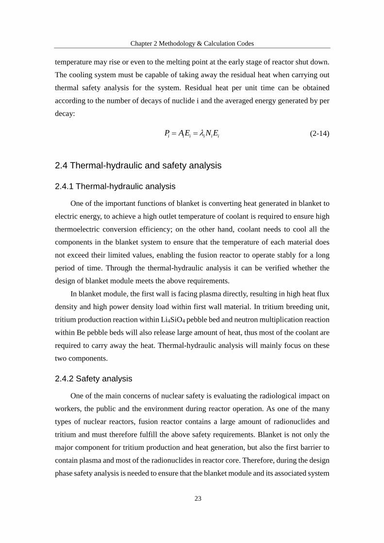
Table 3-1 Composition in CFETR HCCB TBM
Component Zone Material Thickness/mm
W Armor Tungsten 2
Fw Helium(23%)+RAFM
Steel(77%)
30
Outer Be Zone Zone 1- Parallel To
FW
Be Pebble Bed 20/40
Outer Be Zone Zone 2-
Perpendicular To
FW
Be Pebble Bed 51.5
Outer Be Zone Zone 3-
Perpendicular To
FW
Be Pebble Bed 51.5
Li4SiO4 Zone Zone 1- Parallel To
FW
Li4SiO4pebble Bed 20
Li4SiO4 Zone Zone 2-
Perpendicular To
FW
Li4SiO4pebble Bed 20
Chapter 3 Neutronic Study of HCCB-TBM
32
Table 3-1(Continued) composition in CFETR HCCB TBM
Component Zone Material Thickness/mm
Li4SiO4 Zone Zone 3-
Perpendicular To
FW
Li4SiO4pebble Bed 20
Inner Be Zone Be Pebble Bed 75
Upper Cap Helium(5%)+RAFM
Steel(95%)
30
Lower Cap Helium(5%)+RAFM
Steel(95%)
30
Stiff Grid RAFM Steel 10
Backplate Helium(40%)+RAFM
Steel(60%)
170
Figure 3-4 cross section view of CFETR HCCB TBM
3.3 Neutronic model and calculation procedure
The neutron and photon transport simulation was performed using MCNP Monte
Carlo transport code and ENDF/VI neutron cross section data. The configuration of the
CFETR from the plasma to the TF coil consists of the first wall (FW), breeding units,
manifold, back plate support (BP), shield, vacuum vessel (VV), thermal shield (TS) and
toroidal field coil (TFC). The HCCB blanket is composed of a tungsten amour 3 mm thick,
an FW, breeder unit, stiffening grid and back plate. As the main purpose of this thesis is
to perform neutronic analysis for blanket module, detailed structural model of other
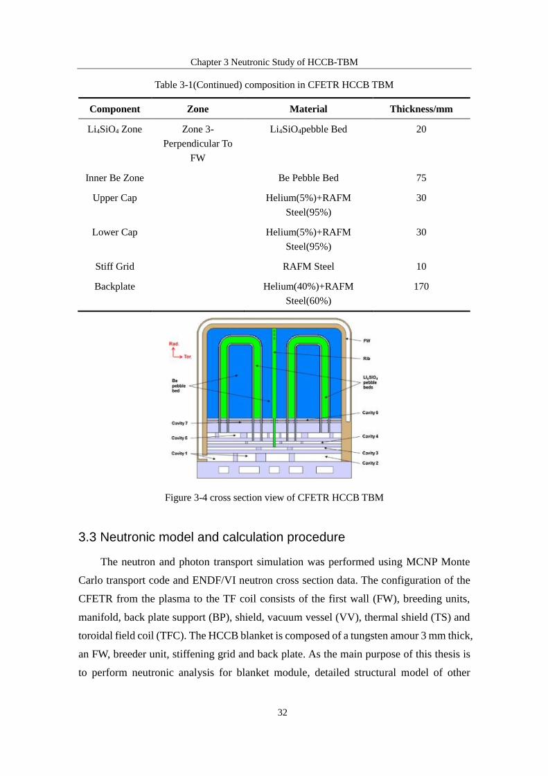
Chapter 3 Neutronic Study of HCCB-TBM
33
components like Vacuum Vessel and coils (TF and PF coils) were not given in this work.
(a) 2D model of CFETR HCCB TBM (b) 3D model in MCNP
Figure 3-5 2D and 3D model of CFETR HCCB TBM
3.3.1 Neutron wall loading
Neutron wall loading (NWL) is the average fusion neutron power loaded per unit
area of the first wall (FW) surface. Its distribution determines the material selection and
structural layout of the components in the fusion reactor. Specifically, it influences the
operational life of the components, the level of material damage, and the shielding
arrangement of fusion reactor.
The fusion power is 134 MW, and the corresponding neutron source is 4.75*1019 n/s.
The calculation procedure is shown as equation 3-1:
n
0.8 fusionn
n n
PPS
E E (3-1)
Where term Pn is core fusion neutron power, considering the self-heating of alpha
particles, fusion neutron power is 4/5 of core fusion neutron power. En=14.06 MeV is the
released fusion energy per D-T reaction. With the given neutron source, NWL can be
obtained through neutron flux tally in MCNP (NWL=neutron source*F2 tally in MCNP).

Chapter 3 Neutronic Study of HCCB-TBM
34
Figure 3-6 Neutron wall loading distribution
Figure 3-6 shows the neutron wall loading distribution in each polarity blanket
module. The maximum NWL appears at outboard blanket No. 11, which is 0.45 MW/m2.
The maximum neutron wall loading for inboard blanket is 0.35 MW/m2 which appears at
No. 4 blanket. The NWL distribution indicates that equatorial blanket No. 11 faces the
most serious operation condition, thus the safety analysis will focus on this module.
3.3.2 Tritium breeding ratio (TBR)
The total TBR calculated from the initial model was 1.084, and the distribution of
the TBR of each blanket module was shown in Figure 3-7.
Figure 3-7 TBR distribution
It can be seen that each module produces a clear bimodal distribution. The modules
with the largest contribution of the inner and outer modules are No. 4 and No. 10,
respectively, that means, the production performance of the modules close to the equator
is the best; the output of the outer module accounts for 62.7% of the total TBR, which

Chapter 3 Neutronic Study of HCCB-TBM
35
indicates that the contribution of outboard modules to TBR accounts for a major portion.
The MCNP particle track shows that the collision of the neutrons at the equatorial plane
with the blanket is the most concentrated and is consistent with the calculated results. The
result is credible.
Figure 3-8 Particle tracks in MCNP
3.3.3 Optimization design for tritium breeding
In last section the total TBR of the initial model was obtained. The requirement for
TBR is no less than 1.20 for CFETR, considering tritium losses. Thus the tritium self-
sustainability is still a major challenge in neutronic design. In this section issues that may
have influence on tritium breeding capability of blanket have been studied to optimize
the tritium breeding performance.
3.3.3.1 Arrangement schemes of pebble beds
Different arrangement scheme of tritium breeding material and neutron
multiplication material can directly influence the tritium breeding capability of blanket
module as it involves the lithium/beryllium ratio, neutron distribution in blanket and
neutron ultilization rate. Three different parameters related to pebble beds arrangements
were studied in this paper. D1 is the thickness of beryllium pebble beds parallel to first
wall, D2 is the thickness of inner beryllium pebble beds, and D3 is the thickness of
Li4SiO4 pebble beds.

Chapter 3 Neutronic Study of HCCB-TBM
36
Figure 3-9 Material layout in sub-module
a) Influence of D1 on TBR
The initial thickness of beryllium pebble beds parallel to the first wall are 25 mm
and 45 mm for inboard and outboard blanket respectively, and the initial thickness of D2
and D3 are 85 mm and 20mm. By verifying D1, Li4SiO4 pebble beds are set closer to
plasma to see how TBR changes. Different D1 schemes and their corresponding TBR are
listed in Table 5, for each scheme D2 and D3 are remained unchanged.
Table 3-2 TBR as a function of D1
Arrangement
Scheme
D1 in inboard
blanket/mm
D1 in
outboard
blanket /mm
Volume percentage of
tritium breeding zone in
outboard blanket
TBR
a 25 45 16.74% 1.0839
b 25 40 16.88% 1.0896
c 25 35 17.02% 1.0927
d 25 30 17.16% 1.0980
e 25 25 17.30% 1.1034
From Table 3-2 it can be concluded that TBR increases as D1 decreases, that’s
because there are more fast neutrons entering Li4SiO4 pebble beds. Decreasing D1 means
that there is less neutron multiplication material to breeding neutron, but the TBR can still
be increased.
Chapter 3 Neutronic Study of HCCB-TBM
37
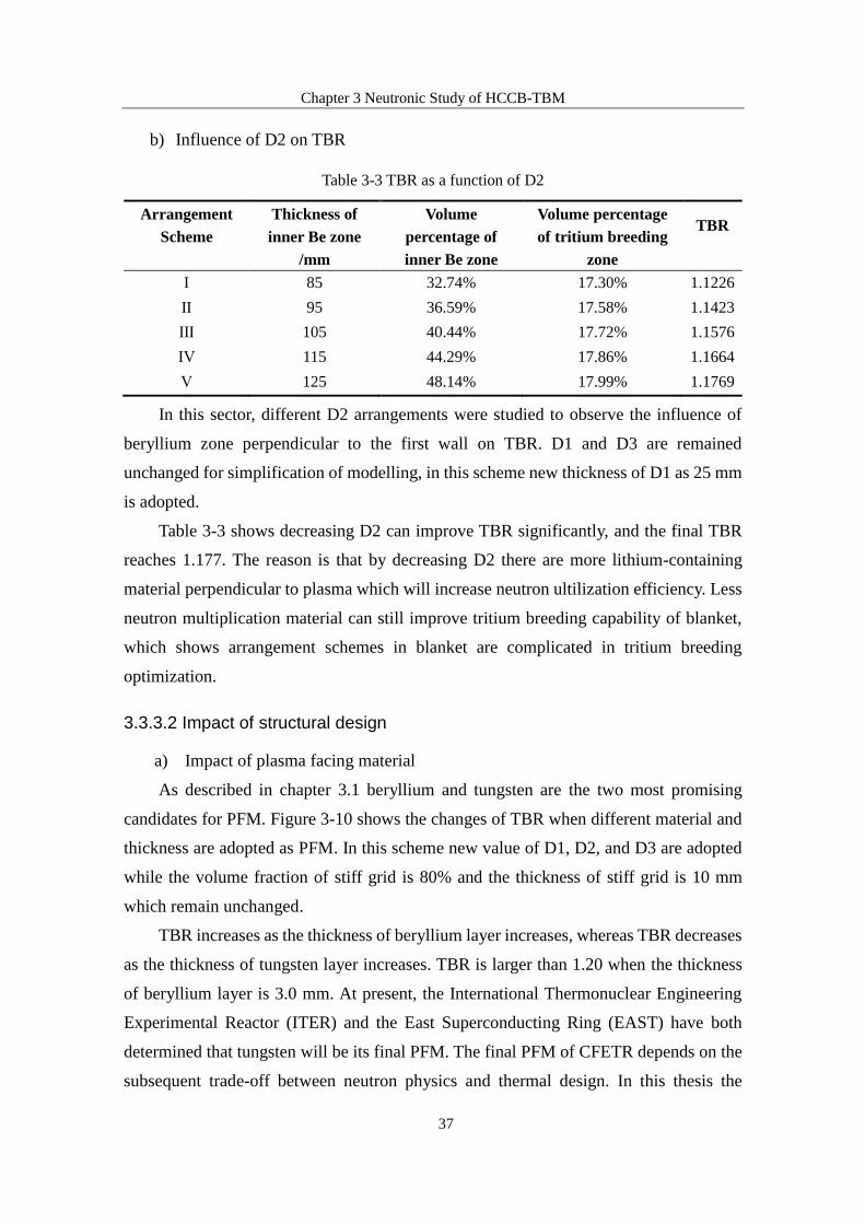
b) Influence of D2 on TBR
Table 3-3 TBR as a function of D2
Arrangement
Scheme
Thickness of
inner Be zone
/mm
Volume
percentage of
inner Be zone
Volume percentage
of tritium breeding
zone
TBR
Ⅰ 85 32.74% 17.30% 1.1226
Ⅱ 95 36.59% 17.58% 1.1423
Ⅲ 105 40.44% 17.72% 1.1576
Ⅳ 115 44.29% 17.86% 1.1664
Ⅴ 125 48.14% 17.99% 1.1769
In this sector, different D2 arrangements were studied to observe the influence of
beryllium zone perpendicular to the first wall on TBR. D1 and D3 are remained
unchanged for simplification of modelling, in this scheme new thickness of D1 as 25 mm
is adopted.
Table 3-3 shows decreasing D2 can improve TBR significantly, and the final TBR
reaches 1.177. The reason is that by decreasing D2 there are more lithium-containing
material perpendicular to plasma which will increase neutron ultilization efficiency. Less
neutron multiplication material can still improve tritium breeding capability of blanket,
which shows arrangement schemes in blanket are complicated in tritium breeding
optimization.
3.3.3.2 Impact of structural design
a) Impact of plasma facing material
As described in chapter 3.1 beryllium and tungsten are the two most promising
candidates for PFM. Figure 3-10 shows the changes of TBR when different material and
thickness are adopted as PFM. In this scheme new value of D1, D2, and D3 are adopted
while the volume fraction of stiff grid is 80% and the thickness of stiff grid is 10 mm
which remain unchanged.
TBR increases as the thickness of beryllium layer increases, whereas TBR decreases
as the thickness of tungsten layer increases. TBR is larger than 1.20 when the thickness
of beryllium layer is 3.0 mm. At present, the International Thermonuclear Engineering
Experimental Reactor (ITER) and the East Superconducting Ring (EAST) have both
determined that tungsten will be its final PFM. The final PFM of CFETR depends on the
subsequent trade-off between neutron physics and thermal design. In this thesis the

Chapter 3 Neutronic Study of HCCB-TBM
38
tungsten armor with the thickness of 2 mm is adopted.
Figure 3-10 Changes of TBR with different thickness of PFM
b) Impact of stiff grid
The main function of the stiff grid is to provide reinforcement for the blanket, and
some coolant channels are also installed in the stiff grid to remove heat deposited in the
blanket structure. Figure 3-11 shows the results of TBR calculations for stiff grid with
different thicknesses and RAFM steel volume fractions.
Figure 3-11 Changes of TBR with different thickness of the stiff grid

Chapter 3 Neutronic Study of HCCB-TBM
39
It can be seen that lowering the volume fraction of RAFM steel can effectively
increase TBR, but at the same time, the volume fraction of structural material must not
be much low to undermine the mechanical properties of the blanket structure. The
thickness of the stiff grid design in this paper is 10mm, and the volume fraction of
structural material RAFM steel is 70%.
3.4 Heat deposition distribution
The energy generated by the fusion reaction is ultimately transferred in the form of
heat energy in the reactor components. The study of the nuclear thermal energy
distribution of the blanket can verify whether the overall fusion power of the reactor meets
the requirements. It also provides data support for subsequent thermal-hydraulic analysis
and safety analysis.
Table 3-4 Nuclear heat deposition in blanket module
Blanket NO. Heat Deposition/MW
#1 0.39
#2 0.70
#3 0.82
#4 0.85
#5 0.67
#6 0.38
#7 0.77
#8 0.80
#9 0.82
#10 1.19
#11 1.19
#12 0.74
#13 0.59
Total 9.91
After optimization of tritium breeding the TBR reaches 1.177, which meets the
minimum tritium self-sustainability requirement (TBR ≥ 1.05). Table 3-4 shows the heat
deposition in each blanket module. Blanket No. 10 and No. 11 have the highest heat

Chapter 3 Neutronic Study of HCCB-TBM
40
deposition, which is consistent with the TBR distribution.
Table 3-5 Power density of each component in module 10
Components Power Density MW/m3
Tungsten armor 4.152
First wall (facing plasma) 9.922
First wall-left side 1.190
First wall-right side 1.191
Top cap 2.425
Bottom cap 3.187
Back plate 0.124
Inner Be zone 3.424
Outer Be zone 2.194
Stiff grid 3.830
Li4SiO4 pebble beds 9.434
Blanket No. 10 and No. 11 are faced with the most severe operation conditions since
they have the highest heat deposition. Future thermal-hydraulic and safety analysis should
be carried out for these two modules. Table 3-5 gives the heat deposition in each
components of blanket 10 as source data for thermal-hydraulic and safety analysis.
It can be seen that the highest power density located in tritium breeding zone and the
first wall (facing plasma side). The power density of back plate is only 0.124 MW/m3.
Thermal-hydraulic analysis should be focused on the design of coolant path flow in the
first wall and in the tritium breeding zone.
3.5 Summary
The material adoption and structural design of a helium cooled ceramic breeder
blanket concept proposed by SWIP for CFETR is given in details in this chapter, and
neutronic study is performed by Monto Carlo transport code MCNP. The optimization for
tritium breeding ratio is investigated, including the influence of different arrangements
and different structural design. The result shows that the final TBR is 1.177, which can
satisfy the tritium self-sufficiency requirement. Other neutronic parameters including
neutron wall loading and heat distribution in blanket are also calculated in this chapter.

Chapter 4 Thermal Hydraulic Analysis of HCCB-TBM
41
Chapter 4 Thermal Hydraulic Analysis of HCCB-TBM
The design of the blanket is an iterative process. First neutronic analysis was
performed to verify whether the blanket module satisfies the tritium self-efficiency
requirement. Then the neutron-generated heat deposition was used as the input parameter
for thermal analysis, and the thermal-hydraulic performance of the structure was
evaluated. If it does not meet the requirements, it is necessary to optimize the design of
the blanket, and re-calculation of the neutronic and thermal-hydraulic parameters are
required. Such process is repeated until the design requirements are satisfied. Heat
deposition was obtained from neutronic analysis in last chapter. In this chapter, thermal-
hydraulic analysis was performed to evaluate whether the design requirements are
satisfied.
4.1 Coolant flow scheme in TBM
Table 4-1 Power density and heat deposition distribution
Components Power density MW/m3 Power MW
Tungsten armor 4.152 6.50E-1
First wall (facing plasma) 9.922 3.64E-1
First wall-left side 1.190 2.85E-2
First wall-right side 1.191 2.87E-2
Top cap 2.425 7.17E-2
Bottom cap 3.187 9.14E-2
Back plate 0.124 2.27E-2
Inner Be zone 3.424 1.29E-1
Outer Be zone 2.194 1.45E-1
Stiff grid 3.830 8.64E-2
Li4SiO4 pebble beds 9.434 2.33E-1
Total 1.89
Since blanket module #10 has the highest power deposition, which means it faces
the most severe operation conditions, thermal-hydraulic analysis will be performed for
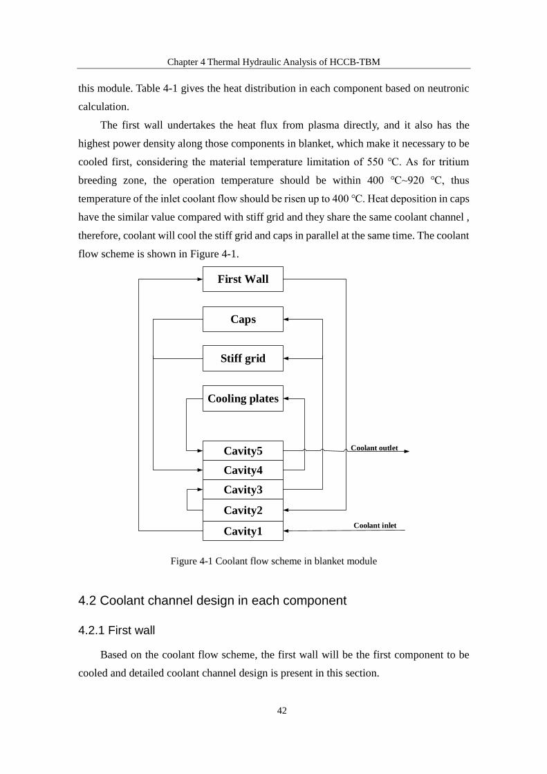
Chapter 4 Thermal Hydraulic Analysis of HCCB-TBM
42
this module. Table 4-1 gives the heat distribution in each component based on neutronic
calculation.
The first wall undertakes the heat flux from plasma directly, and it also has the
highest power density along those components in blanket, which make it necessary to be
cooled first, considering the material temperature limitation of 550 ℃. As for tritium
breeding zone, the operation temperature should be within 400 ℃~920 ℃, thus
temperature of the inlet coolant flow should be risen up to 400 ℃. Heat deposition in caps
have the similar value compared with stiff grid and they share the same coolant channel ,
therefore, coolant will cool the stiff grid and caps in parallel at the same time. The coolant
flow scheme is shown in Figure 4-1.
Figure 4-1 Coolant flow scheme in blanket module
4.2 Coolant channel design in each component
4.2.1 First wall
Based on the coolant flow scheme, the first wall will be the first component to be
cooled and detailed coolant channel design is present in this section.
First Wall
Caps
Stiff grid
Cooling plates
Cavity5
Cavity4
Cavity3
Cavity2
Cavity1Coolant inlet
Coolant outlet

Chapter 4 Thermal Hydraulic Analysis of HCCB-TBM
43
Figure 4-2 Coolant channel in first wall
As shown in Figure 4-2, the polar length of the first wall is 1010mm, the radial length
is 800mm, the circumferential length is 1302mm, thickness of first wall is 30mm. A
rectangular flow channel is adapted and the height in polar direction is 14mm, and 12mm
in radial direction. The distance between each channel is 4.5mm, so there are a total of 54
coolant channels in the first wall. Coolant flows in opposite direction in two adjacent
channels to even temperature distribution in first wall.
4.2.2 Caps and Stiff grid
The top and bottom of blanket are sealed by caps. The top and bottom caps have the
same structure and the thickness is 28mm. Figure 4-3 shows the schematic structure of
caps. The inlet and outlet coolant channel locates at the rear of the cap. Coolant moves in
radial direction at the inlet which is connected to the second helium cavity, whereas it
moves in polar direction and is collected in the third helium cavity.
The thickness of top and bottom caps is 28mm, and W-shaped coolant channel is
adapted to remove the heat deposited in caps and partially deposited in tritium breeding
zone. As shown in Figure 4-3, totally 22 flow channels are set inside the caps which
rectangular coolant channel is adopted. The size of each flow channel is 7 mm in polar
direction, and 10 mm in circumferential direction. The distance between two adjacent
channels is 4 mm.

Chapter 4 Thermal Hydraulic Analysis of HCCB-TBM
44
Figure 4-3 Coolant channel in caps
The same coolant channel design is adapted in caps and stiff grid in order to simplify
the structure. The polar height for stiff grid in blanket #10 is 950 mm. for W-shaped
coolant channel, the size of each channel is 4 mm in circumferential direction and 8 mm
in polar direction, and the distance between two adjacent channels is set to 8 mm. There
are totally 14 flow channels in each stiff grid.
4.2.3 Cooling plate
The Li4SiO4 zone is separated from beryllium pebble beds by two U-shaped cooling
plates. The amount of structural steel in cooling plates should be minimized to increase
the blanket tritium breeding capability as much as possible. However, due to the limitation
of wire cutting accuracy, the thickness of a single cooling plate is set to 5 mm. Rectangular
coolant channel is adapted and the length of each channel is 4.5 mm in polar direction
and 2.5 mm in circumferential direction. The distance between two adjacent channels is
set to 2.9 mm. The polar height for each sub-module is 950 mm, which means there are a
total of 128 coolant channels in each cooling plate.
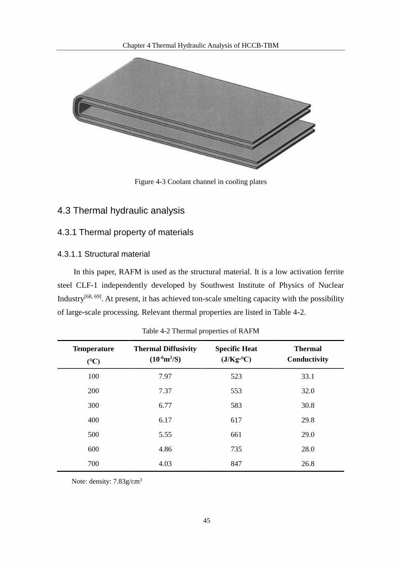
Chapter 4 Thermal Hydraulic Analysis of HCCB-TBM
45
Figure 4-3 Coolant channel in cooling plates
4.3 Thermal hydraulic analysis
4.3.1 Thermal property of materials
4.3.1.1 Structural material
In this paper, RAFM is used as the structural material. It is a low activation ferrite
steel CLF-1 independently developed by Southwest Institute of Physics of Nuclear
Industry[68, 69]. At present, it has achieved ton-scale smelting capacity with the possibility
of large-scale processing. Relevant thermal properties are listed in Table 4-2.
Table 4-2 Thermal properties of RAFM
Temperature
(℃)
Thermal Diffusivity
(10-6m2/S)
Specific Heat
(J/Kg‧℃)
Thermal
Conductivity
100 7.97 523 33.1
200 7.37 553 32.0
300 6.77 583 30.8
400 6.17 617 29.8
500 5.55 661 29.0
600 4.86 735 28.0
700 4.03 847 26.8
Note: density: 7.83g/cm3

Chapter 4 Thermal Hydraulic Analysis of HCCB-TBM
46
4.3.1.2 Li4SiO4
Li4SiO4 is chosen as tritium breeding material in this paper. At present, China has
achieved kilogram-level production capacity of Li4SiO4 by using the melt spray method
and a series of tests will be performed on ITER-TBM. Relevant thermal properties such
as thermal conductivity are listed in Table 4-3[70]. The study of the release behavior of
lithium silicate beads shows that when the pebble beds’ temperature is higher than 400 ℃,
it has good transport properties to avoid the formation of tritium deposition in Li4SiO4,
and its maximum temperature is limited to 920 ℃ to avoid sintering which affects the
release of tritium in the pebble beds.
Table 4-3 Thermal properties of Li4SiO4 pebble bed
Physical
Properties Value
Pebble bed size 1 mm
Packing factor 60%
Pebble bed
density 1.44 g/cm3
Thermal
conductivity
4 7 2( / ) 0.97198 5.04496 10 ( ) 3.30432 1 0 ) (W m K T T ℃ ℃
Specific heat 6 2( / ) 1.57753 0.00179 ( ) 2.22244 10 ( )pc J kg K T T ℃ ℃
Thermal
diffusivity
2 4 7 2( / ) 0.54761 4.08679 10 ( ) 1.95 1 265 0 ( )mm s T T ℃ ℃
4.3.1.3 Beryllium
Table 4-4 Thermal properties of beryllium pebble bed
Physical
Properties Value
Pebble bed size 0.2~1.4 mm (double size)
Packing factor 80%
Pebble bed density 1.13 g/cm3
Thermal
conductivity
4( / ) 7.31451 1.00652 10 ( ) W m K T ℃
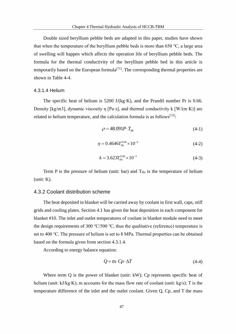
Chapter 4 Thermal Hydraulic Analysis of HCCB-TBM
47
Double sized beryllium pebble beds are adapted in this paper, studies have shown
that when the temperature of the beryllium pebble beds is more than 650 ℃, a large area
of swelling will happen which affects the operation life of beryllium pebble beds. The
formula for the thermal conductivity of the beryllium pebble bed in this article is
temporarily based on the European formula[71]. The corresponding thermal properties are
shown in Table 4-4.
4.3.1.4 Helium
The specific heat of helium is 5200 J/(kg·K), and the Prandtl number Pr is 0.66.
Density [kg/m3], dynamic viscosity η [Pa·s], and thermal conductivity k [W/(m·K)] are
related to helium temperature, and the calculation formula is as follows[72]:
48.091 HeP T (4-1)
0.66 60.4646 10HeT (4-2)
0.66 33.623 10Hek T (4-3)
Term P is the pressure of helium (unit: bar) and THe is the temperature of helium
(unit: K).
4.3.2 Coolant distribution scheme
The heat deposited in blanket will be carried away by coolant in first wall, caps, stiff
grids and cooling plates. Section 4.1 has given the heat deposition in each component for
blanket #10. The inlet and outlet temperatures of coolant in blanket module need to meet
the design requirements of 300 ℃/500 ℃, thus the qualitative (reference) temperature is
set to 400 ℃. The pressure of helium is set to 8 MPa. Thermal properties can be obtained
based on the formula given from section 4.3.1.4.
According to energy balance equation:
mQ Cp T (4-4)
Where term Q is the power of blanket (unit: kW); Cp represents specific heat of
helium (unit: kJ/kg‧K); m accounts for the mass flow rate of coolant (unit: kg/s); T is the
temperature difference of the inlet and the outlet coolant. Given Q, Cp, and T the mass

Chapter 4 Thermal Hydraulic Analysis of HCCB-TBM
48
flow rate of coolant m can be obtained from equation 4-4 which is 1.82 kg/s.
The coolant flow scheme is given in section 4.1. Based on the heat deposited in each
component the mass flow rate and temperature rise can be determined according to energy
balance conservation. The total temperature rise in back plate system is 2.4 ℃, which
means averaged temperature rise in each cavity is very small. This temperature rise can
be neglected in pressure drop calculation process compared to total temperature rise of
200 ℃. Table 4-5 gives the corresponding coolant mass flow rate and temperature rise in
each component:
Table 4-5 Coolant flow scheme in blanket module
Component Mass flow rate kg/s Temperature rise ℃
First wall 1.82 107.1
Caps 1.19 26.4
Stiff grids 0.63 26.3
Cooling plate 1 0.91 66.8
Cooling plate 2 0.91 66.8
Back plate system 1.82 2.4
4.3.3 Coolant pressure drop in each component
The flow of fluid in the tube will produce a pressure drop due to energy loss, which
is mainly divided into friction pressure drop and partial pressure drop. The pressure drop
is an important parameter in thermal-hydraulic analysis as it affects thermal properties of
coolant. The friction pressure drop is the pressure loss along the way when the fluid flows
along the flow path due to the obstruction. This obstruction comes from the friction
between fluid elements or fluid layers and the fluid and solid wall surfaces along the path.
Elements that affect friction pressure drop include fluid density, flow path size and
roughness of the surface and others. Partial pressure drop is the local obstruction caused
by the sudden change of the shape, size, or direction of the flow passage when the fluid
flows, and the vortex, deformation, and velocity redistribution in the fluid cause violent
collisions between the fluid particles, resulting in partial pressure drop. Partial pressure
drop is mainly located at the inlet, outlet and curved sections of the flow channel.

Chapter 4 Thermal Hydraulic Analysis of HCCB-TBM
49
Coolant flow scheme in each component has been given in section 4.2. The
theoretical calculation for pressure drop in first wall is given in details in the following
part, pressure drop in other components is obtained in similar procedure. As all the
coolant channels are parallel with each other in first wall, pressure drop calculation is
performed in one single channel as it represents the total pressure drop in first wall.
Coolant velocity should be the first parameter to be given in order to calculate
pressure drop in first wall. Total mass flow rate in first wall is 1.82kg/s, and temperature
rise is 107.14 ℃, thus the qualitative (reference) temperature is 353.57 ℃. The property
of helium is determined with its qualitative (reference) temperature. Velocity of coolant
is determined as the following:
c
c
mu
A (4-5)
Where uc is velocity of coolant, m represents mass flow rate in first wall, is
density of coolant, and cA is total inlet flow area of coolant in first wall. Giving m,
and cA , the velocity of coolant can be obtained from equation 4-5 which is 33 m/s.
Figure 4-4 Pressure drop in first wall
As shown in Figure 4-4, the total pressure drop in first wall consist of three friction
loss and four local loss:
3 4
1 1
fi fj
i j
P P P
(4-6)
Calculation formula for friction loss is:

Chapter 4 Thermal Hydraulic Analysis of HCCB-TBM
50
21
2f c
h
lP f u
D (4-7)
Where term f is friction loss coefficient; l is the length of coolant channel (unit: m);
Dh is hydraulic diameter (unit: m); is coolant density (unit: kg/m3); uc is velocity of
coolant (unit: m/s).
The definition of hydraulic diameter for noncircular channel is written as the
following:
4 c
h
AD
P (4-8)
Ac is cross section of coolant channel (unit: m2); P is wetted perimeter (unit: m).
For smooth tube, calculation formula for friction loss factor proposed by Petukhov
is widely used as it is applied in a large range of Reynolds number:
2 6(0.79ln Re 1.64) 3000 Re 5 10D Df (4-9)
Where ReD is Reynolds number, and the definition of which is:
Re c h c hD
u D u D
v
(4-10)
Term is density of coolant (unit: kg/m3); uc is velocity of coolant (unit: m/s); Dh
represents hydraulic diameter of coolant channel (unit: m); is dynamic viscosity of
coolant and v is kinematic viscosity of coolant.
The Reynolds number is 7.81E+04, which is within the range of Petukhov’s formula.
For local loss the calculation formula is:
21
2s cP u (4-11)
Where is local loss coefficient, is density of coolant and uc is velocity.
The local pressure loss coefficient is 0.5 and 1 respectively at the inlet and outlet of
the coolant channel, in the curved section it is determined by the following formula:
3.5
0.131 0.159180
hD
R
(4-12)

Chapter 4 Thermal Hydraulic Analysis of HCCB-TBM
51
Term is angle at the curved section (unit: degree); R is radius of the curvature
(unit: m); Dh is hydraulic diameter of the channel (unit: m).
Based on the formula above, the total pressure drop in the channel in first wall is
22.38 kPa, along which friction pressure drop is 13.71 kPa. As all the coolant channels
are parallel with each other in first wall, the total pressure drop of coolant in first wall is
22.38 kPa.
The pressure drop of helium in each component is listed in Table 4-6, the properties
of helium are related to helium temperature to reach a more accurate calculation result.
The total pressure drop of helium is 186.41 kPa when the pressure drop of helium in inlet
and outlet pipes and in cavity is not included, which accounts for 2.3% of the working
pressure of helium.
Table 4-6 Pressure drop in each component
Components Averaged velocity of helium/m‧s-1 Averaged pressure drop/kPa
First wall 33.00 22.38
Cap 70.73 131.43
Stiff grid 64.36 139.18
Cooling plate #1 29.20 29.81
Cooling plate #2 29.20 27.64
4.3.4 Helium cooling system
The function of helium cooling system (HCS) is removing heat generated in blanket
modules to the secondary cooling system by forced convection of helium for electricity
generation. The design of CFETR helium cooling system has not been finished yet, in
this thesis HCS design is based on the CH HCSB TBM helium cooling subsystem for
ITER[73].
The primary helium loop is forced circulation with relevant components including
blanket module, tritium extraction system, helium makeup tank, coolant filter, buffer
volume, heat exchanger, helium circulator, recuperator, valves and adjacent pipes, etc.
For secondary loop, water is employed as coolant with 35/75 ℃ as inlet/outlet
temperature under the operation pressure of 1 MPa. The system configuration is shown
in Figure 4-5.

Chapter 4 Thermal Hydraulic Analysis of HCCB-TBM
52
Figure 4-5 Sketch of helium cooling system
c) Heat exchanger
The heat exchanger is a component in which heat is transferred from primary side to
secondary side. Multi-coiled tube bundle heat exchanger (MCHX) will be adapted and
the advantage is that this type of tubes can largely eliminate thermal stress due to the large
temperature difference on the helium side. In order to further attenuate the thermal stress
possibly induced by large temperature difference between the helium side and the water
side, current design of the helium cooling subsystem has adopted a recuperator for
reducing the mean temperature on the helium side of the main heat exchanger. The helium
volume in the HX will be 0.14 m3 (the volume of the shell side of the HX).
d) Electrical heater
The electric heater is designed for heating the whole helium cooling subsystem
including the TBM to operating temperatures and for baking the first wall of the TBM up
to 300 °C after maintenance or repair periods.
e) Dust filter
The function of dust filter is to absorb residual dust and particles from fabrication,
and erosion particles with a typical size of about 10-6 m.

Chapter 4 Thermal Hydraulic Analysis of HCCB-TBM
53
f) circulator
Circulator is used to drive the circulation of the primary coolant helium. The helium
volume contained in the circulator is either 0.025 m3 or 0.05 m3 depending on whether
one circulator or two circulators be employed in final TBM design. The overall
dimensions of one circulator and drive unit with the insulation are expected to be a
diameter of 0.8 m and a height of 2.1 m.
g) Pipeline
The pipeline of the main helium loop, including hot leg, cold leg and elbows, are
constructed by standardized pipes with an inner diameter of 80 mm and a wall thickness
of 7.5 mm.
The main design parameters of the helium cooling system are encompassed in the
Table 4-7 depicted as follows.
Table 4-7 Envelop dimensions and weights of the helium cooling loop components
Component Number per loop Diameter
(m)
Length
(m)
Weight
(kg)
Helium/water heat exchanger 1 0.45 3 600
Recuperator 1 0.45 3 600
Circulator, vertical shaft 2 0.40 0.5 340
Circulator drive motor 1 0.50 1.0 400
Dust filter (without shield) 1 0.50 3.5 1120
Main pipeline 1 0.08 195 1900
Helium storage tank 2 0.50 3.0 1240
Helium dump tanks 3 0.60 2.4 1770
Buffer tank for pressure control 1 0.35 2.6 475
Test Module 1
Electrical heater 1 0.34 2.2 250
Total mass of TBM and cooling
system 8695

Chapter 4 Thermal Hydraulic Analysis of HCCB-TBM
54
4.3.5 Nodalization of HCS in RELAP5
Figure 4-6 HCS nodalization in RELAP5
The primary loop of helium cooling system is simulated in detail with RELAP5. The
HCS sketch is shown in Figure 4-6. Hydraulic components like volume, pipes and pump
in RELAP5 are used to simulate components in HCS. As the objective of this thesis is to
analysis the steady-state operation and transition behavior of blanket module, detailed
modelling of blanket module is present whereas other components in HCS is simplified
in RELAP5 nodalization. The heat exchanger is simulated with two pipes which represent
the primary and secondary side for simplicity, and a constant flowrate of water in
secondary side is simulated with time dependent junction component of RELAP5. Heat
structures in blanket module are set to rectangular type while cylindrical heat structures
are adapted in other components.
4.3.5.1 Modeling of FW
The First wall is simulated with two pipes in order to perform accident analysis. As
described in section 4.2.1, there are total 54 coolant channels in the first wall with 12 mm
(in diameter) × 14 mm (in height). One pipe component 040 represents 48 coolant
channels in first wall, and the other pipe 042 represents the rest 6 coolant channels where
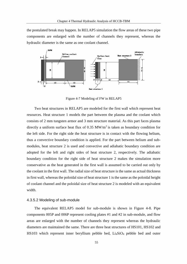
Chapter 4 Thermal Hydraulic Analysis of HCCB-TBM
55
the postulated break may happen. In RELAP5 simulation the flow areas of these two pipe
components are enlarged with the number of channels they represent, whereas the
hydraulic diameter is the same as one coolant channel.
Figure 4-7 Modeling of FW in RELAP5
Two heat structures in RELAP5 are modeled for the first wall which represent heat
resources. Heat structure 1 models the part between the plasma and the coolant which
consists of 2 mm tungsten armor and 3 mm structure material. As this part faces plasma
directly a uniform surface heat flux of 0.35 MW/m2 is taken as boundary condition for
the left side. For the right side the heat structure is in contact with the flowing helium,
thus a convective boundary condition is applied. For the part between helium and sub-
modules, heat structure 2 is used and convective and adiabatic boundary condition are
adopted for the left and right sides of heat structure 2, respectively. The adiabatic
boundary condition for the right side of heat structure 2 makes the simulation more
conservative as the heat generated in the first wall is assumed to be carried out only by
the coolant in the first wall. The radial size of heat structure is the same as actual thickness
in first wall, whereas the poloidal size of heat structure 1 is the same as the poloidal height
of coolant channel and the poloidal size of heat structure 2 is modeled with an equivalent
width.
4.3.5.2 Modeling of sub-module
The equivalent RELAP5 model for sub-module is shown in Figure 4-8. Pipe
components 005P and 006P represent cooling plates #1 and #2 in sub-module, and flow
areas are enlarged with the number of channels they represent whereas the hydraulic
diameters are maintained the same. There are three heat structures of HS101, HS102 and
HS103 which represent inner beryllium pebble bed, Li4SiO4 pebble bed and outer

Chapter 4 Thermal Hydraulic Analysis of HCCB-TBM
56
beryllium pebble bed respectively. Rectangular geometry for heat structures are adapted.
On both sides of HS101 and HS102 a convective boundary condition is used while for
HS103 adiabatic boundary condition is used for the right side. This makes the simulation
more conservative since heat transfer between beryllium pebble bed and stiff grid is
neglected.
Figure 4-8 Modeling of sub-module in RELAP5
4.3.5.3 Steady state analysis
Figure 4-9 Helium temperature of steady-state

Chapter 4 Thermal Hydraulic Analysis of HCCB-TBM
57
Figure 4-9 and Figure 4-10 show the coolant temperature and pressure simulating
results at blanket module under steady state operation, respectively. The obtained helium
temperatures at TBM inlet/outlet are 573K/775K, approximately to be the designed
573K/773K.
The coolant pressure drops are about 0.02 MPa in the FW, and 0.19 MPa in the whole
TBM.
Figure 4-10 Helium pressure of steady-state
After getting steady state, the helium mass flow rate is about 1.816 kg/s at the cold
and hot legs. Figure 4-11 shows the temperature distribution of FW materials. The
tungsten armor maximum temperature is about 922 K, and it is under the margin of the
allowable value for tungsten armor. The maximum temperature of FW structure material
is 854 K, which is below the design limits.
Figure 4-11 Temperature distribution in first wall (K)
The maximum temperatures in pebble beds are shown in Figure 4-12. The maximum
temperature of Li4SiO4 pebble bed is about 990.6 K, and for beryllium pebble bed the
922
854
816
680(He)
720 755

Chapter 4 Thermal Hydraulic Analysis of HCCB-TBM
58
maximum temperature is 816.9 K. The temperatures are within design limits.
Figure 4-12 Maximum temperature in pebble beds (K)
Figure 4-13 Maximum temperature in HS103 (K)
The maximum temperature for outer beryllium zone locates near the stiff grid side
after the corner, Figure 4-13 gives a more detailed temperature distribution in the spot.
Based on neutronic study, the power density in pebble beds is exponentially decaying in
the radial direction, which means the closer to the FW, the higher the power density. The
coolant has gained a large part of total temperature rise after cooling the parallel pipe to
FW part of pebble bed. This area is far away from coolant channel, causing the
temperature in this spot is the highest in outer beryllium pebble bed. Considering
Helium761.68 816.99
Adiabatic
boundaryConvective
boundary
803.51

Chapter 4 Thermal Hydraulic Analysis of HCCB-TBM
59
adiabatic boundary condition is applied in the right side, the highest temperature appears
at the right side of outer beryllium pebble bed as there is no heat transfer between this
side and stiff grid.
The maximum temperature location in Li4SiO4 and inner beryllium pebble beds are
given in Figure 4-14 and 4-15, respectively. As these two pebble beds are surrounded by
coolant channels the maximum temperature appears in the middle of pebble beds.
Figure 4-14 Maximum temperature in HS102 (K)
Figure 4-15 Maximum temperature in HS101 (K)
The simulated temperature distribution in each component is listed in Table 4-7. The
results show that maximum temperature of each material is within their design limits.
Table 4-7 Maximum temperature of each material and their design limits
Material Maximum temperature/K Design limit/K
RAFM 854 873
Li4SiO4 991 1193
Beryllium 817 923
Convective
boundary
Helium
005P
774.19 768.71
Convective
boundary
990.59 Helium
006P
Convective
boundary
Helium
005P
738.75 739.21
Convective
boundary
746.09 Helium
005P

Chapter 4 Thermal Hydraulic Analysis of HCCB-TBM
60
4.4 Summary
Based on the heat distribution given in chapter 3, thermal-hydraulic analysis is
performed for typical blanket module in this chapter. Coolant flow scheme is given in
first section. Coolant temperature rise and pressure drop in each component are simulated,
the helium cooling system model is established in RELAP5, and the results show that
maximum temperature of each material is within the design limits.

Chapter 5 Accident Analysis of HCCB-TBM
61
Chapter 5 Accident Analysis of HCCB-TBM
Blanket is not only the major component for tritium production and heat generation,
but also the first barrier to contain plasma and most of the radionuclides in reactor core.
Therefore, during the design phase safety analysis is needed to ensure that blanket module
and its associated system can remain intact and stable under normal operation, and
withstand heat and force load in the expected event.
5.1 Safety function of blanket system
The blanket system consists of tritium breeder blanket module, shield blanket
module, Helium Cooling System (HCS), Tritium Extraction System (TES), Coolant
Purification System (CPS) and Data Acquisition and Control System (DACS) which
contains a large amount of radionuclides and tritium. The following gives a brief
description of each sub-system.
a) Helium Cooling System (HCS)
This system is supposed to extract the heat generated in blanket module by providing
helium at given pressure and temperature required by blanket module. The components
(compressor, heat exchanger, etc.) and the piping allocated in the TCWS vault are part of
this system.
b) Tritium extraction system (TES)
The function of this system is to remove the tritium produced in the blanket and to
control the gas composition of the purge gas flow. This system is connected to the blanket
and its allocation is anticipated in the Tritium Building.
c) Coolant purification system (CPS)
The function of this system is to remove tritium and other impurities in the coolant,
and control the gas composition in the helium cooling system. This system is connected
to the HCS loop and is also anticipated in the tritium building.
The blanket system is the first barrier for containing radioactive material, and the
second barrier is its surrounding buildings, including Vacuum Vessel, Port Cell, Tritium
Building and CVCS Vault, etc. Under normal operation radionuclides except tritium are
immobile whereas they may become mobile radioactive source when radionuclides are

Chapter 5 Accident Analysis of HCCB-TBM
62
released under system leakage events. Therefore, in the design phase, it is necessary to
perform accident analysis to evaluate the integrity and stability of the blanket under
accident scenarios, and ensuring that it is capable of withstanding the heat and force load
in the expected events.
The safety functions of blanket system are listed as follows:
a) Subsystem isolation;
b) Gas release control in the overpressure subsystem;
c) Triggering fusion reactor central security system to issue shutdown signal in time.
Three security facilities have been set up to ensure the safety function of blanket
system to respond timely and effectively.
The isolation subsystem (helium coolant system, tritium extraction system, coolant
purification system) is designed to limit accidental pressurization or to prevent
radioactive fluids from entering the vacuum vessel. The result of the isolation is to seal
the gas and mobile radioactive activation products within the entire blanket system,
keeping them away from the vacuum vessel and other reactor systems.
Pressure control system is the second security facility to achieve helium supply,
pressure control and overpressure protection function. The pressure control unit is nearly
isolated from the main cooling loop during normal operation. However, the buffer tank
will discharge the stored helium into the main loop when the primary helium cooling loop
has a pressure drop caused by a small leak or by a loss of coolant accident. For system
overpressure, considering that the excitation response may be very close to the isolation
response value, each circuit is designed with multiple pressure release lines. The main
loop of the helium cooling system (including the circulator and pressure control system)
and the coolant purging system release to the storage tank in the area of the chemical-
capacity control system during overpressure, and the other parts are vented to the storage
tank anticipated in the Port Cell.
The function of fusion power termination system (FPTS) is terminating the fusion
reaction in plasma in time so that the heat source and neutron loads can be terminated
under accident scenario. Once helium cooling system fails, in addition to isolating the
cracked circuit, the plasma needs to be shut down in time. However, due to the long-term
exposure of neutrons, materials are activated which means decay heat will be generated
after the plasma is shut down. These decay heats can be discharged passively by natural
convection and thermal radiation. The heat is gradually transferred from the blanket to

Chapter 5 Accident Analysis of HCCB-TBM
63
the vacuum vessel cooling system, and finally is carried out by the natural convection of
the vacuum chamber cooling system.
5.2 Accident analysis
5.2.1 Postulated Initiator Events (PIEs)
Table 5-1 Total list of PIEs identified by the FMEA
PIEs Description
LFC-1 Loss of flow in a TBM cooling circuit
LFC-2 Partial flow blockage in a TBM cooling circuit
LHS-1 Loss of heat sink in TBM coolant-He
IBC-1 In breeder region loss of TBM coolant-He: Rupture of a sealing weld
IBC-2 In breeder region loss of TBM coolant-He: Leak of a sealing weld
LVV-1 LOCA out-VV: large rupture of TBM coolant pipe in TWCS room
LVV-2 LOCA out-VV: small rupture of TBM coolant pipe in TWCS room
LVV-3 LOCA out-VV: rupture of tubes in a primary TBM-HCS HX
LVP-1 LOCA out-VV: rupture of TBM coolant pipe in Port Cell
LVP-2 LOCA out-VV: small rupture of TBM coolant pipe in Port Cell
IVC-1 In-VV loss of TBM coolant-He: Rupture of TBM-FW
IVC-2 In-VV loss of TBM coolant-He: leak from TBM-FW
LVC-1 LOCA out-VV: small rupture of PFW/BLK coolant pipe in Port Cell
LIV-1 Small PFW/BLK LOCA in-VV: equivalent break size-a few cm2
RVP-1 Small rupture of VV coolant pipe in Port Cell
LVV-1 Small rupture in the internal VV shell-equivalent break size: a few cm2
LTG-1 Leak of TBM-TES process line in Glove Box containment
LTP-1 Leak of TBM-TES process line in Port Cell
VBG-1 Loss of vacuum in VV: break inside the VV of TBM purge gas system
VBG-2 Loss of vacuum in VV: leak inside VV from TBM purge gas system
AVV-1 Ingress of air in the VV-small leakage
N/S Not safety relevant
(Note: VV means Vacuum Vessel; HX means Heat Exchanger; PFW means Primary First Wall;
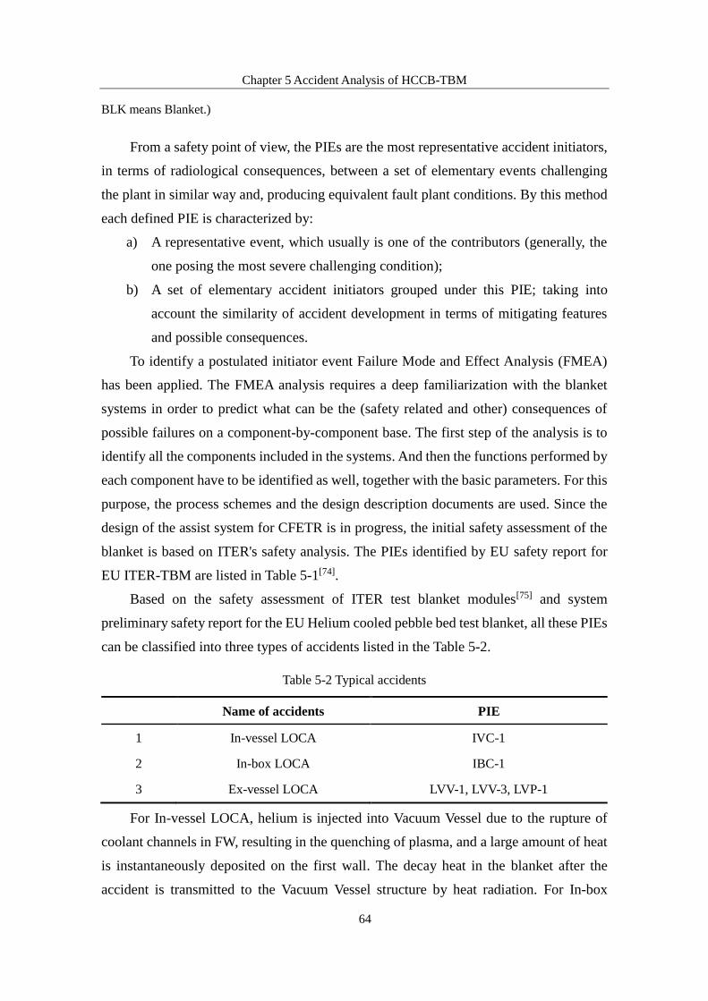
Chapter 5 Accident Analysis of HCCB-TBM
64
BLK means Blanket.)
From a safety point of view, the PIEs are the most representative accident initiators,
in terms of radiological consequences, between a set of elementary events challenging
the plant in similar way and, producing equivalent fault plant conditions. By this method
each defined PIE is characterized by:
a) A representative event, which usually is one of the contributors (generally, the
one posing the most severe challenging condition);
b) A set of elementary accident initiators grouped under this PIE; taking into
account the similarity of accident development in terms of mitigating features
and possible consequences.
To identify a postulated initiator event Failure Mode and Effect Analysis (FMEA)
has been applied. The FMEA analysis requires a deep familiarization with the blanket
systems in order to predict what can be the (safety related and other) consequences of
possible failures on a component-by-component base. The first step of the analysis is to
identify all the components included in the systems. And then the functions performed by
each component have to be identified as well, together with the basic parameters. For this
purpose, the process schemes and the design description documents are used. Since the
design of the assist system for CFETR is in progress, the initial safety assessment of the
blanket is based on ITER's safety analysis. The PIEs identified by EU safety report for
EU ITER-TBM are listed in Table 5-1[74].
Based on the safety assessment of ITER test blanket modules[75] and system
preliminary safety report for the EU Helium cooled pebble bed test blanket, all these PIEs
can be classified into three types of accidents listed in the Table 5-2.
Table 5-2 Typical accidents
Name of accidents PIE
1 In-vessel LOCA IVC-1
2 In-box LOCA IBC-1
3 Ex-vessel LOCA LVV-1, LVV-3, LVP-1
For In-vessel LOCA, helium is injected into Vacuum Vessel due to the rupture of
coolant channels in FW, resulting in the quenching of plasma, and a large amount of heat
is instantaneously deposited on the first wall. The decay heat in the blanket after the
accident is transmitted to the Vacuum Vessel structure by heat radiation. For In-box

Chapter 5 Accident Analysis of HCCB-TBM
65
LOCA, coolant will inject into tritium breeding zone when the structure of cooling plate
is broken, causing the overpressure in the blanket box. The difference between In-vessel
LOCA and In-box LOCA is that the quenching of plasma will not happen in In-box LOCA
as the blanket remains intact at the beginning of In-box LOCA, which means the fusion
reaction will continue until it is terminated by fusion power termination system (FPTS).
Considering the most conservative assumption, i.e. the blanket completely losses coolant,
then the temperature of structural material will rise to its melting point, the intact of
blanket box cannot be assured. For Ex-vessel LOCA, helium is released from components
outside Vacuum Vessel, which means the quenching of plasma will not happen at the
beginning during this accident. The thermal effect of Ex-vessel LOCA is the same as the
most severe case of In-box LOCA. As the intact of blanket box cannot be assured under
the most severe case of In-box LOCA and Ex-vessel LOCA, human intervention is needed
to prevent the blanket melting. For In-vessel LOCA, the heat mainly comes from the
decay of activated materials as the plasma is terminated because of the ingress of helium
compared with In-box LOCA and Ex-vessel LOCA. In this thesis, In-vessel LOCA is
investigated in details to evaluate the integrity of blanket module.
5.2.2 In-vessel LOCA
This postulated event assumes the rupture of 6 FW cooling pipes. The primary side
coolant leaks directly into the Vacuum Vessel and the plasma is inherently shutdown by
the ingress of coolant. After quenching of the plasma, the production of neutron is stopped,
and the TBM heat mainly comes from the decay of radioactive isotopes.
Figure 5-1 In-vessel LOCA model in RELAP5
941 valve
950
VV
050
Man
ifold
1
040 FW
042 FW
030
Man
ifold
2
020
Grid, top &
bottom plates
010
Man
ifold
3

Chapter 5 Accident Analysis of HCCB-TBM
66
Table 5-3 Accident sequence
Parameter Specification
T=0 (sec) Rupture of coolant channel in FW
0<T<0.1
Fusion power terminated by helium ingress
100% nuclear power density and surface heat flux
Additional disruption load 5.52MW/m2
Decay heat
0.1≤T<1.0
100% nuclear power density and surface heat flux
Additional disruption load 0.72MW/m2
Decay heat
T≥1.0 Plasma quench
Decay heat
The RELAP5 model of the break is shown in Figure 5-1. The broken part between
FW and VV is modeled by valve 941. At steady-state, the valve is closed. When a in-
vessel LOCA happens, the valve is opened and the helium gas will erupt into VV from
FW, the electrical power is disconnected from the pump motor. When the pressure of the
coolant system is below 7.2 MPa, the valve of the helium makeup tank is opened. Before
the LOCA happening, the pressure in the makeup tank is 12 MPa, and the temperature is
323 K. Pressure in VV is 1Pa, and the temperature is 443 K. The broken area is 0.00101
m2.
Table 5-4 Acceptance criteria
Parameter Specification
VV pressure Pressure of VV < 200 kPa
Helium load Helium injected into VV < 45 kg
Accident sequence is listed in Table 5-3, and acceptance criteria is listed in Table 5-
4. Due to the plasma disruption the FW will face a huge disruption load at the beginning
of the accident.
Figure 5-2 shows the pump velocity evolution. Figure 5-3 shows the helium mass
flow rate for TBM inlet/outlet, breaking FW, Sub-module and pump inlet. It is obvious
that the TBM inlet mass flow rate has a big increase at the beginning of the LOCA, and
then decreases to about zero after about 35 seconds. The coolant of Sub-module and TBM
outlet both have a reverse flow at the LOCA initiation, and the reverse flow is very severe

Chapter 5 Accident Analysis of HCCB-TBM
67
for the breaking FW.
Figure 5-2 Pump velocity
Figure 5-3 Mass flow rate in in-vessel LOCA
Figure 5-4 and Figure 5-5 show helium load and pressure of Vacuum Vessel,
respectively. The 1350 m3 VV is pressurized to a small value of about 23 kPa (He
temperature approximately 549 K, with total mass of 17.2 Kg), which is less than the
ITER design limit of 200 kPa, and the safety of vacuum vessel can be ensured.

Chapter 5 Accident Analysis of HCCB-TBM
68
Figure 5-4 Helium Load in VV in in-vessel LOCA
Figure 5-5 Pressure in VV in in-vessel LOCA
5.3 Summary
Accident analysis is carried out for blanket module under typical accident scenarios
based on the failure module and effect analysis methodology in this chapter. Transient
behavior of blanket module is investigated in RELAP5, and the result shows that the
safety of vacuum vessel can be ensured in In-Vessel LOCA.

Chapter 6 Summary and Conclusions
69
Chapter 6 Summary and Conclusions
Based on the concept of helium-cooled ceramic breeder blanket proposed by
Southwest Institute of Physics (SWIP), an updated blanket design with good tritium
production capability, simple structure and relatively small pressure drop of coolant was
given in this dissertation. With the updated blanket structure, the thermal-hydraulic and
safety analysis of the typical blanket module were performed, and the rationality of the
design scheme of the blanket was evaluated.
Through the development of neutron physics design, the tritium production
capability of this blanket has been studied. In the neutronics design, the effects of the
pebble bed structure and layout on the tritium breeding ratio (TBR), the influence of the
blanket structure design and materials on the TBR were studied, and the variation trend
of the tritium breeding performance of the blanket with different designs was obtained.
With the optimized design, the total TBR reached 1.17, which can meet the tritium self-
sufficiency goal (TBR≥1.05). On the basis of this, the thermal deposition distribution of
the whole blanket module was obtained, and the detailed distribution of the power density
of the various components of the typical blanket module on the equatorial plane was given.
On the basis of obtained nuclear thermal distribution of a typical blanket module,
the design of blanket cooling structure and thermal-hydraulics analysis were carried out.
The temperature rise and pressure drop of the coolant in each component were obtained
through the separate analysis of the cooling pipes in each component based on the coolant
flow scheme. Through the separate analysis of the components in the blanket, the thermal-
hydraulic parameters of each component were obtained. The simulated results showed
that the maximum temperature of each component was within the design limit value of
the material, and the blanket could meet the thermal design requirements.
The accidental safety analysis of the blanket helium cooling system was performed
by the general system transient behavior analysis program, RELAP5. In the case of an in-
vessel LOCA accident, the first wall coolant pipe will rupture and the coolant enters the
vacuum vessel. The pressure in vacuum vessel reached 23 kPa, which was lower than the
ITER vacuum vessel structure design standard (200 kPa). The safety of the blanket system
under the accident can be guaranteed.

References
70
References
[1] LAWSON J D. Some Criteria for a Power Producing Thermonuclear Reactor: Physical Society,
1957[C].
[2] MORGAN, LEE W G. Inertial confinement fusion neutronics[J]. University of York, 2012.
[3] MCNALLY J R J. NUCLEAR FUSION RESONANCE REACTIONS OF POSSIBLE CTR
INTEREST.[J]. Chemistry of Materials, 1971,8(12):2839-2842.
[4] NUCKOLLS J, WOOD L, THIESSEN A, et al. Laser Compression of Matter to Super-High
Densities: Thermonuclear (CTR) Applications[J]. Nature, 1972,239(5368):139-142.
[5] MASSUMI B. Role played by O A Lavrent'ev in the formulation of the problem and the
initiation of research into controlled nuclear fusion in the USSR[J]. Physics-Uspekhi,
2001,171(8):12-17.
[6] GREEN B J. The European Fusion Research and Development Programme and the ITER
Project, 2004[C].
[7] ZMITKO M, GALABERT J, THOMAS N, et al. The European ITER Test Blanket Modules:
Current status of fabrication technologies development and a way forward[J]. Fusion
Engineering & Design, 2015,96-97:199-207.
[8] ZMITKO M, THOMAS N, LIPUMA A, et al. The European ITER test blanket modules:
Progress in development of fabrication technologies towards standardization[J]. Fusion
Engineering & Design, 2016,109-111:1687-1691.
[9] HIROSE T. Recent status of WCCB TBM development in Japan: 14th International Conference
on Nuclear Engineering, 2006[C].
[10] CHO S, AHN M Y, DONG W L, et al. Design and R&D progress of Korean HCCR TBM[J].
Fusion Engineering & Design, 2014,89(7-8):1137-1143.
[11] FENG K M, ZHANG G S, HU G, et al. New progress on design and R&D for solid breeder test
blanket module in China[J]. Fusion Engineering & Design, 2014,89(7–8):1119-1125.
[12] BHATTACHARYAY R. Status of Indian LLCB TBM program and R&D activities[J]. Fusion
Engineering & Design, 2014,89(7–8):1107-1112.
[13] WAN Y. Design and strategy for the fusion engineering testing reactor (CFETR)[J]. 2013.
[14] LIU S, PU Y, CHENG X, et al. Conceptual design of a water cooled breeder blanket for
CFETR[J]. Fusion Engineering & Design, 2014,89(7-8):1380-1385.
[15] NI M, LIAN C, ZHANG S, et al. Structural design and preliminary analysis of liquid lead–
lithium blanket for China Fusion Engineering Test Reactor[J]. Fusion Engineering & Design,
2015,94(1):61-66.
[16] KUAN W, ABDOU M A. A New Approach for Assessing the Required Tritium Breeding Ratio
and Startup Inventory in Future Fusion Reactors[J]. Fusion Technology, 1999,35(3):309-353.

References
71
[17] GLUGLA M, MURDOCH D K, ANTIPENKOV A, et al. ITER fuel cycle R&D: Consequences
for the design[J]. Fusion Engineering & Design, 2006,81(1):733-744.
[18] SAWAN M E, ABDOU M A. Physics and technology conditions for attaining tritium self-
sufficiency for the DT fuel cycle[J]. Fusion Engineering & Design, 2006,81(8):1131-1144.
[19] GLUGLA M, LÄSSER R, DÖRR L, et al. The inner deuterium/tritium fuel cycle of ITER[J].
Fusion Engineering & Design, 2003,69(1–4):39-43.
[20] GLUGLA M, ANTIPENKOV A, BELOGLAZOV S, et al. The ITER tritium systems[J].
Fusion Engineering & Design, 2007,82(5):472-487.
[21] FISCHER U, BACHMANN C, JABOULAY J C, et al. Neutronic performance issues of the
breeding blanket options for the European DEMO fusion power plant[J]. Fusion Engineering
& Design, 2016,109-111:1458-1463.
[22] NAJMABADI F, ABDOU A, BROMBERG L, et al. The ARIES-AT advanced tokamak,
Advanced technology fusion power plant[J]. Fusion Engineering & Design, 2006,80(1):3-23.
[23] FISCHER U, BACHMANN C, PALERMO I, et al. Neutronics requirements for a DEMO
fusion power plant[J]. Fusion Engineering & Design, 2015,98-99:2134-2137.
[24] CHEN H, PAN L, LV Z, et al. Tritium fuel cycle modeling and tritium breeding analysis for
CFETR[J]. Fusion Engineering & Design, 2016,106:17-20.
[25] XIE Z, Deng L. Numerical Calculation Method for Neutron Transport Theory [M].
Northwestern Polytechnical University Press, 2005.
[26] CHEN Y, FISCHER U, PERESLAVTSEV P, et al. The EU Power Plant Conceptual Study –
Neutronic Design Analyses for Near Term and Advanced Reactor Models[J].
Wissenschaftliche Berichte Fzka, 2003.
[27] QIU L. Fusion Energy and Its Application[M]. Tsinghua University Press, 2007.
[28] BRIESMEISTER J F E. MCNP - A General Monte Carlo N-Particle Transport Code, 2003[C].
[29] ROMANO P K, FORGET B. The OpenMC Monte Carlo particle transport code[J]. Annals of
Nuclear Energy, 2013,51:274-281.
[30] DUNN M E, GREENE N M, HOLLENBACH D F, et al. MONTE CARLO METHODS
DEVELOPMENT FOR A CONTINUOUS ENERGY VERSION OF KENO[J]. 2005.
[31] LEPPÄNEN J. PSG2/Serpent - A Continuous-energy Monte Carlo Reactor Physics Burnup
Calculation Code[J]. Vtt Technical Research Centre of Finland, 2013.
[32] BRUN E, DUMONTEIL E, HUGOT F X, et al. Overview of TRIPOLI-4 version 7, continuous-
energy Monte Carlo Transport Code: Icapp, 2011[C].
[33] MARLEAU G, EBERT A, ROY R. A USER GUIDE FOR DRAGON VERSION4[J]. 2013.
[34] JEFFREY A. A brief user's guide for PARTISN[J]. 2011.
[35] DOWNAR, THOMAS, COLLINS, et al. MPACT Theory Manual, Version 2.2.0[J]. 2016.
[36] SANCHEZ R, MONDOT J, STANKOVSKI, et al. APOLLO II: A User-Oriented, Portable,
Modular Code for Multigroup Transport Assembly Calculations[J]. Nuclearence &
Engineering, 1988,100(3):352-362.

References
72
[37] BOYD W, SHANER S, LI L, et al. The OpenMOC method of characteristics neutral particle
transport code[J]. Annals of Nuclear Energy, 2014,68(3):43-52.
[38] JERZY C, PIOTR G. BISON-C upgraded one- dimensional transport and burnup calculation
code for unix system[J]. 2000.
[39] CROFF A G. A User's Manual for the ORIGEN2 Computer Code[J]. Ibm Corp,
1980,388(2):148-149.
[40] FORREST R A, SUBLET J C. FISPACT-99 : user manual[J]. Journal of Hospice & Palliative
Nursing, 1998,4(4):206-207.
[41] FORREST R A. The European Activation System: EASY-2007 overview[J]. 2007.
[42] PIET S J, BARTELS H W, GORDON C W, et al. ITER principal safety functions: radiological
confinement, heat removal, and shutdown[J]. Fusion Engineering .sofe.seeking A New Energy
Era.ieee/npss Sympo, 1995,1:301-304.
[43] D'AURIA F, DUSIC M, DUTTON L M C, et al. Deterministic Safety Analysis for Nuclear
Power Plants. IAEA Specific Safety Guide[J]. 2009.
[44] PAPAZOGLOU I A, BARI R A, BUSLIK A J, et al. Probabilistic safety analysis procedures
guide[J]. Specific Nuclear Reactors & Associated Plants, 1984.
[45] SLOAN S M, SCHULTZ R R, WILSON G E. RELAP5/MOD3 code manual[J]. NUREG/CR-
4312, EGG-2396, 1992.
[46] WANG Y, ZHANG L, ZHAO Z, et al. Preliminary accident analyses of in-vessel LOCA and
In-box LOCA for China helium-cooled ceramic breeder test blanket system[J]. Fusion
Engineering & Design, 2016,112:548-556.
[47] LIAN Q, CUI S, TIAN W, et al. Preliminary accident analysis of Loss of Off-Site Power and
In-Box LOCA for the CFETR helium cooled solid breeder blanket[J]. Fusion Engineering &
Design, 2017,118:142-150.
[48] CHENG X, MA X, CHEN Y, et al. Preliminary thermal hydraulic safety analysis of water-
cooled ceramic breeder blanket for CFETR[J]. Journal of Nuclear Science & Technology,
2016,53(11):1673-1680.
[49] MURGATROYD J T, OWEN S, GRIEF A, et al. Qualification of MELCOR and RELAP5
models for EU HCPB TBS accident analyses[J]. Fusion Engineering & Design, 2017,124:1251-
1256.
[50] JIANG K, LI J, ZHANG X, et al. The Development and Application of One Thermal–Hydraulic
Program Based on ANSYS for Design of Ceramic Breeder Blanket of CFETR[J]. Journal of
Fusion Energy, 2015,34(5):1088-1093.
[51] BALUC N L. On the potentiality of using ferritic/martensitic steels as structural materials for
fusion reactors: 19th IAEA Fusion Energy Conference, 2002[C].
[52] LOOMIS B A, SMITH D L. Vanadium alloys for structural applications in fusion systems: a
review of vanadium alloy mechanical and physical properties[J]. Journal of Nuclear Materials,
1992,s 191–194(3):84-91.

References
73
[53] KATOH Y, SNEAD L L, JR C H H, et al. Current status and critical issues for development of
SiC composites for fusion applications[J]. Journal of Nuclear Materials, 2007,s 367–
370(5):659-671.
[54] JOHNSON C E, NODA K, ROUX N. Ceramic breeder materials: Status and needs[J]. Journal
of Nuclear Materials, 1998,s 258–263(s 258–263):140-148.
[55] KUNIHIKOTSUCHIYA, MASARUNAKAMICHI, YOSHIHARUNAGAO, et al. In-situ
Tritium Recovery Experiments of Blanket In-pile Mockup with Li2TiO3 Pebble Bed in
Japan[J]. Journal of Nuclear Science & Technology, 2001,38(11):996-1003.
[56] NAKAGAWA H, ASANO M, KUBO K. Mass spectrometric investigation of the vaporization
of Li2TiO3(s)[J]. Journal of Nuclear Materials, 1982,110(2–3):158-163.
[57] BELOGLAZOV S, NISHIKAWA M, TANIFUJI T. Modelling of tritium release from
irradiated Li2ZrO3[J]. Fusion Science & Technology, 2002,41(3):1049-1053.
[58] MONTANARO L, LECOMPTE J P. Preparation via gelling of porous Li2ZrO3 for fusion
reactor blanket material[J]. Journal of Materials Science, 1992,27(14):3763-3769.
[59] ETHRIDGE J L, BAKER D E, MILLER A D. ChemInform Abstract: Effects of Fast Neutron
Irradiation on Thermal Conductivity of Li2O and LiAlO2[J]. Cheminform, 1988,19(37):294-
296.
[60] SHLUGER A, ITOH N, NODA K. Mechanisms of tritium diffusion in Li2O: quantum-
chemical simulation[J]. Journal of Physics Condensed Matter, 1991,3(49):9895.
[61] FISCHER A K, JOHNSON C E. Thermodynamics of the Li2O fusion reactor breeder[J].
Journal of Nuclear Materials, 1984,126(3):268-275.
[62] MÖLLENDORFF U V, ALEVRA A V, GIESE H, et al. Measurements of 14 MeV neutron
multiplication in spherical beryllium shells[J]. Fusion Engineering & Design, 1995,28(95):737-
744.
[63] SCAFFIDI-ARGENTINA F, PIAZZA G, ROLLI R. Microstructural analysis of beryllium
samples irradiated at high temperature[J]. Fusion Engineering & Design, 2003,69(1–4):505-
509.
[64] SMID I, AKIBA M, VIEIDER G, et al. Development of tungsten armor and bonding to copper
for plasma-interactive components[J]. Journal of Nuclear Materials, 1998,s 258–263(4):160-
172.
[65] JOCHEN L. High Heat Flux Performance of Plasma Facing Materials and Components Under
Service Conditions in Future Fusion Reactors[J]. Fusion Science & Technology,
2006,61(2):293-302.
[66] WU C H, MSZANOWSKI U. A comparison of lifetimes of beryllium, carbon, molybdenum
and tungsten as divertor armour materials[J]. Journal of Nuclear Materials, 1995,218(3):293-
301.
[67] DAVIS J W, BARABASH V R, MAKHANKOV A, et al. Assessment of tungsten for use in
the ITER plasma facing components1 #AC-3013 with Sandia National Laboratories.1[J].
Journal of Nuclear Materials, 1998,s 258–263(4):308-312.

References
74
[68] WANG P H, CHEN J M, XU Z Y, et al. FTP/P1-24 Research and Development of Reduced
Activation Ferritic/Martensitic Steel CLF-1 at SWIP[J]. 2010.
[69] WANG P, CHEN J, XU Z, et al. Preliminary results on research of CLF-1 steel: Abstracts Book
of the Ninth China-Japan Symposium on Materials for Advanced Energy Systems and Fission
& Fusion Engineering Jointed with CAS-JSPS Core-university Program Seminar on Fusion
Materials, System and Design Integration, 2007[C].
[70] FENG Y, FENG K, LIU Y, et al. Experimental Investigation of Thermal Properties of the
Li4SiO4 Pebble Beds[J]. 2015.
[71] DALLE-DONNE M, GORAIEB A, PIAZZA G, et al. Measurement of thermal conductivity
and heat transfer coefficient of a binary bed of beryllium pebbles[J]. 1997.
[72] XU Z, REY J, FISCHER U, et al. Development of a DEMO Helium Cooled Pebble Bed (HCPB)
Breeder Unit Featured in Flat Plates with Meandering Channels[J]. Wissenschaftliche Berichte
Fzka, 2006.
[73] Wang Jie, Su Guanghui, Tian Wenxi, et al. Transient Characteristic Analyses of Ex—Vessel
Coolant Pipe Break for Chinese Helium—cooled Solid Breeder TBM Based on RELAP5 Code
[J]. Atomic Energy Science and Technology, 2013,47(6):926-932. (in Chinese)
[74] PANAYOTOV D, POITEVIN Y, FURLAN J, et al. Progress in the EU Test Blanket Systems
Safety Studies: Iaea Fusion Energy Conference Fec, 2012[C].
[75] AYMAR R. Generic Site Safety Report[M]. 2001.

Acknowledgements
75
Acknowledgements
I would like to express my sincere gratitude to supervisor Lang Minggang and Zhou
Zhiwei in Institute of Nuclear and New Energy Technology of Tsinghua University for
their meticulous guidance during my graduate student period. The two teachers gave me
meticulous care and help in my study, research, and life. Their rigorous academic attitude,
the pioneering spirit and the high sense of responsibility will have a profound impact on
my future academic career. No matter what kind of industry I work in, or what kind of
position I am in, the habits and principles getting from the two tutors will always guide
me.
I am grateful for the help and support provided by Prof. Waclaw Gudowski and Prof.
Jan Dufek in Royal Institute of Technology during my exchange to Sweden.
I would also like to thank all the students in Division 103 for their support and help.

Resume
76
Resume
Born on November 2, 1993 in Hebi City, Henan Province.
Admitted to the Department of Nuclear Science and Technology of Harbin
Engineering University in August 2011, and graduated with a bachelor's degree in
engineering in July 2015.
Admitted to the Institute of Nuclear and New Energy Technology of Tsinghua
University in September 2015, and have been studied for the master's degree in nuclear
science and technology hitherto.