preliminary ver - bestimg.net · cis own designed image signal processor, ... 20~200 hz direction...
TRANSCRIPT

Rev. 905-0051-Z0
©2016 CIS Corporation. All rights reserved.
3G-SDI/HD-SDI
FULL HD CMOS Color
VCC-HD3
Product Specifications & Operational Manual
Preliminary Ver.1
CIS Corporation
English
VCC-HD3 Rev. 905-0051-Z0
©2016 CIS Corporation. All rights reserved. 1
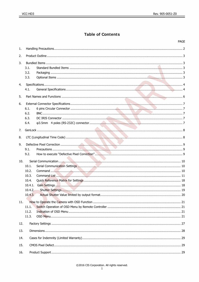
Table of Contents
PAGE
1. Handling Precautions .............................................................................................................................................. 2
2. Product Outline ...................................................................................................................................................... 3
3. Bundled Items ....................................................................................................................................................... 3 3.1. Standard Bundled Items ............................................................................................................................. 3 3.2. Packaging .................................................................................................................................................. 3 3.3. Optional Items ........................................................................................................................................... 3
4. Specifications ......................................................................................................................................................... 4 4.1. General Specifications ................................................................................................................................. 4
5. Part Names and Functions ...................................................................................................................................... 6
6. External Connector Specifications ............................................................................................................................ 7 6.1. 6 pins Circular Connector ............................................................................................................................ 7 6.2. BNC ........................................................................................................................................................... 7 6.3. DC IRIS Connector ..................................................................................................................................... 7 6.4. φ3.5mm 4 poles (RS-232C) connector ....................................................................................................... 7
7. GenLock ................................................................................................................................................................. 8
8. LTC (Longitudinal Time Code) ................................................................................................................................. 8
9. Defective Pixel Correction ....................................................................................................................................... 9 9.1. Precautions ................................................................................................................................................ 9 9.2. How to execute “Defective Pixel Correction” ................................................................................................. 9
10. Serial Communication ....................................................................................................................................... 10 10.1. Serial Communication Settings .................................................................................................................. 10 10.2. Command ................................................................................................................................................ 10 10.3. Command List .......................................................................................................................................... 11 10.4. Quick Reference Matrix for Settings ........................................................................................................... 18 10.4.1. Gain Settings ........................................................................................................................................... 18 10.4.2. Shutter Settings .................................................................................................................................... 19 10.4.3. Actual Shutter Value limited by output format ......................................................................................... 20
11. How to Operate the Camera with OSD Function ................................................................................................. 21 11.1. Switch Operation of OSD Menu by Remote Controller ................................................................................. 21 11.2. Indication of OSD Menu ............................................................................................................................ 21 11.3. OSD Menu................................................................................................................................................ 21
12. Factory Settings ............................................................................................................................................... 27
13. Dimensions ...................................................................................................................................................... 28
14. Cases for Indemnity (Limited Warranty) ............................................................................................................. 29
15. CMOS Pixel Defect ............................................................................................................................................ 29
16. Product Support ............................................................................................................................................... 29
VCC-HD3 Rev. 905-0051-Z0
©2016 CIS Corporation. All rights reserved. 2
1. Handling Precautions
The camera module must not be used for any nuclear equipments or aerospace equipments with which mechanical failure or malfunction could result in serious bodily injury or loss of human life. Our warranty does not apply to damages or defects caused by irregular and/or abnormal use of the product. Please observe all warnings and cautions stated below. Our warranty does not apply to damages or malfunctions caused by neglecting these precautions.
Do not use or store the camera in the dusty or humid places.
Do not apply excessive force, vibration, or static electricity that could damage the camera. Handle the
camera with caution.
Do not shoot direct images that are extremely bright (e.g., light source, sun, etc.), and when camera is
not in use, please put the lens cap on. When extremely strong light source is shot, smear or blooming
may occur.
Follow the instructions in Chapter 6, “External Connector Pin Assignment” for connecting the camera
module. Improper connection may cause damages not only to the camera module but also to the
connected devices.
Confirm the mutual ground potential carefully before connecting the camera to other equipments.
AC leaks from the connected devices may cause damages or destroy the camera.
Do not apply excessive voltage. (Use only the specified voltage.) Unstable or improper power supply
voltage may cause damages or malfunction of the camera assembly.
Since VCC-HD3 is a highly-dense camera module, appropriate heat dissipation shall be considered.
We recommend using a metal base or others to install the camera.

VCC-HD3 Rev. 905-0051-Z0
©2016 CIS Corporation. All rights reserved. 3
2. Product Outline
VCC-HD3 is a full HD color camera module utilizing a 1/1.8 type global shutter CMOS sensor.
Video output 1080 60p/59.94p/50p (3G-SDI), 1080 60i/59.94i/50i/30p/29.97p/25p/24p/23.97p (HD-SDI),
720 60p/59.94p/50p (HD-SDI) are corresponded.
Features
CIS own designed Image Signal Processor, “ClairvuTM” for superb imaging quality.
Small foot print: 29mm × 29mm × 77mm (without protruding portion)
Gen Lock function (3 values analog signals or black burst)
Camera can be controlled by RS-232C
LTC (Longitudinal Time code)
Connecting to an optional remote controller, camera settings can be set by OSD (On Screen Display).
3. Bundled Items
3.1. Standard Bundled Items
Camera module, VCC-HD3
Lens mount cap (attached to the camera)
6pins connector for power
3.2. Packaging
Individual carton
Master carton (10pcs/carton) * Master carton may change depends on the quantity to be shipped per delivery.
3.3. Optional Items
RS-232C conversion cable (φ3.5mm plug <->9pin D-sub) (Planning)
Remote controller (Planning)

VCC-HD3 Rev. 905-0051-Z0
©2016 CIS Corporation. All rights reserved. 4
4. Specifications
4.1. General Specifications
(1) Pickup Device
Device Type 1/1.8 type CMOS sensor (color)
Effective Pixel Numbers 2064(H) × 1544(V)
Unit Cell Size 3.45μm(H) ×3.45μm(V)
Chip Size 7.121mm(H) × 5.327mm(V) (effective pixels)
(2) Resolution 1080p,1080i : 1920(H) × 1080(V)
720p : 1280(H) × 720(V)
(3) Aspect Ratio 16 : 9
(4) Video output format 1920 x 1080p @60fps(Level A) 3G-SDI
1920 x 1080p @60fps(Level B) 3G-SDI
1920 x 1080p @59.94fps(Level A) 3G-SDI
1920 x 1080p @59.94fps(Level B) 3G-SDI
1920 x 1080p @50fps(Level A) 3G-SDI
1920 x 1080p @50fps(Level B) 3G-SDI
1920 x 1080i @60fps HD-SDI
1920 x 1080i @59.94fps HD-SDI
1920 x 1080i @50fps HD-SDI 1920 x 1080p @30fps HD-SDI 1920 x 1080p @29.97fps HD-SDI 1920 x 1080p @25fps HD-SDI 1920 x 1080p @24fps HD-SDI 1920 x 1080p @23.97fps HD-SDI
1280 x 720p @60fps HD-SDI
1280 x 720p @59.94fps HD-SDI
1280 x 720p @50fps HD-SDI
(5) Sync Systems Internal / External Sync.
(6) Video output standard 3G-SDI/HD-SDI : Y/Pb/Pr(4:2:2 10bit) BNC 75Ω terminal
(7) Sensitivity F5.6(TBD) 2000lx
(8) Minimum illumination F1.4 1.25lx(TBD) Conditions : VIDEO 50%, AGC 30dB, Electric shutter OFF
(9) Dust or stains in optical systems
No dust or stain shall be detected on the testing screen with setting the camera aperture at F16.
(10) Power requirement DC+9~+15V
(11) Power consumption (typ.) 4W(TBD) at DC+12V IN
(12) Dimensions Refer to overall dimension drawing
(13) Weight Approx. 92g(TBD)
(14) Lens mount C /CS lens mount (selectable with a conversion ring) ※Please refer to the dimension drawing.
(15) Gain setting AGC (Maximum gain : 0dB~48dB) MANUAL : 0dB~48dB
(16) Shutter speed variable range MANUAL:1/3600s ~ 1/25s
*Shutter speed slower than 1/60s will be limited by the frame rate corresponding to the video
output format. AUTO: 1/3600s ~ 1/25s (Upper limit and lower limit can be set.) *Same as MANUAL, shutter speed slower than 1/60s will be limited by the frame rate
corresponding to the video output format.
(17) White balance adjustment
range
AUTO, AUTO (Outdoor), ATW, 7 different Preset, MANUAL, User Preset 1~5, and One Push Preset: Daylight(5500K),Cloudy(6500K),Shade(8000K),Tungsten(3200K),Fluorescent(White), Fluorescent(Neutral White), Fluorescent(Daylight)
VCC-HD3 Rev. 905-0051-Z0
©2016 CIS Corporation. All rights reserved. 5
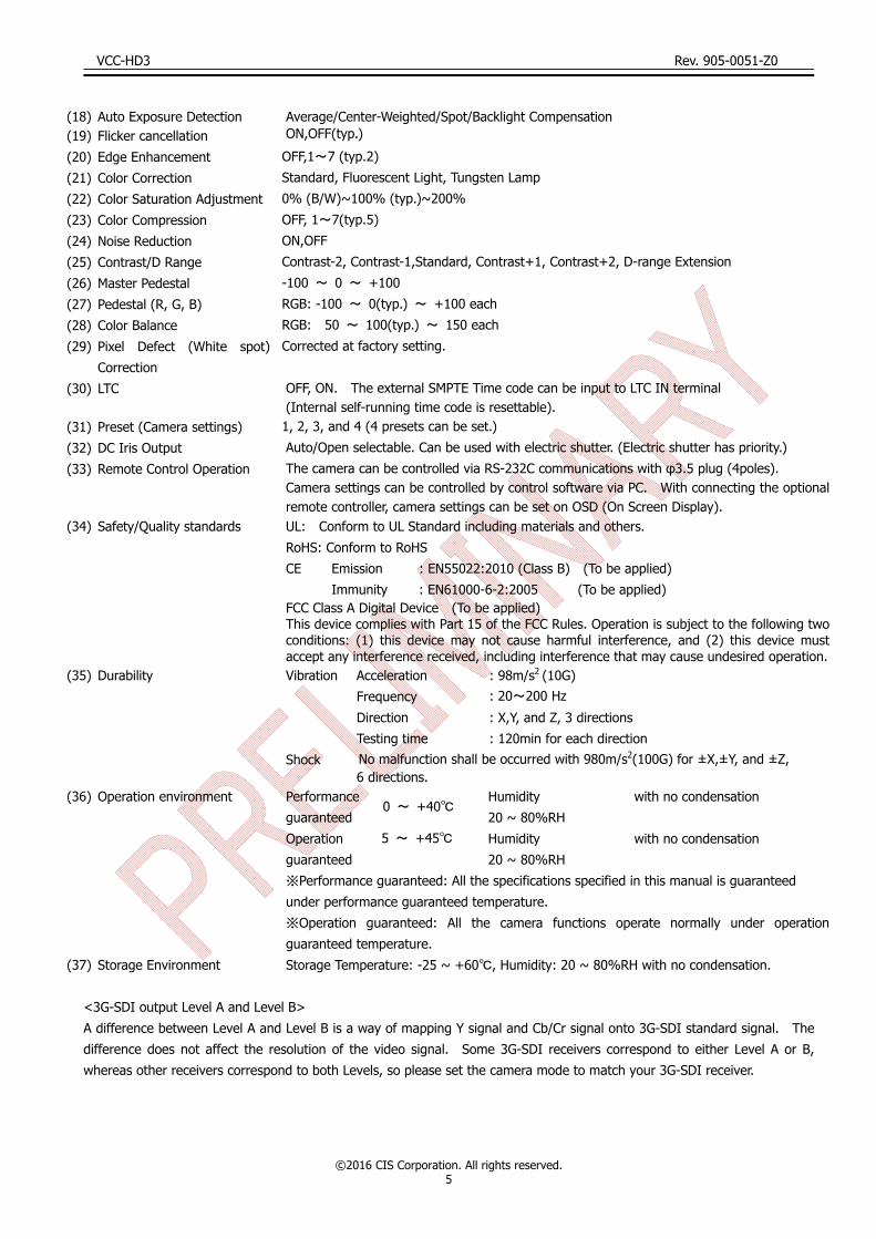
(18) Auto Exposure Detection Average/Center-Weighted/Spot/Backlight Compensation (19) Flicker cancellation ON,OFF(typ.)
(20) Edge Enhancement OFF,1~7 (typ.2)
(21) Color Correction Standard, Fluorescent Light, Tungsten Lamp
(22) Color Saturation Adjustment 0% (B/W)~100% (typ.)~200%
(23) Color Compression OFF, 1~7(typ.5)
(24) Noise Reduction ON,OFF
(25) Contrast/D Range Contrast-2, Contrast-1,Standard, Contrast+1, Contrast+2, D-range Extension
(26) Master Pedestal -100 ~ 0 ~ +100
(27) Pedestal (R, G, B) RGB: -100 ~ 0(typ.) ~ +100 each
(28) Color Balance RGB: 50 ~ 100(typ.) ~ 150 each
(29) Pixel Defect (White spot)
Correction
Corrected at factory setting.
(30) LTC OFF, ON. The external SMPTE Time code can be input to LTC IN terminal (Internal self-running time code is resettable).
(31) Preset (Camera settings) 1, 2, 3, and 4 (4 presets can be set.)
(32) DC Iris Output Auto/Open selectable. Can be used with electric shutter. (Electric shutter has priority.)
(33) Remote Control Operation The camera can be controlled via RS-232C communications with φ3.5 plug (4poles). Camera settings can be controlled by control software via PC. With connecting the optional remote controller, camera settings can be set on OSD (On Screen Display).
(34) Safety/Quality standards UL: Conform to UL Standard including materials and others.
RoHS: Conform to RoHS
CE Emission : EN55022:2010 (Class B) (To be applied)
Immunity : EN61000-6-2:2005 (To be applied) FCC Class A Digital Device (To be applied)This device complies with Part 15 of the FCC Rules. Operation is subject to the following two conditions: (1) this device may not cause harmful interference, and (2) this device must accept any interference received, including interference that may cause undesired operation.
(35) Durability Vibration Acceleration : 98m/s2 (10G)
Frequency : 20~200 Hz
Direction : X,Y, and Z, 3 directions
Testing time : 120min for each direction
Shock No malfunction shall be occurred with 980m/s2(100G) for ±X,±Y, and ±Z, 6 directions.
(36) Operation environment Performance
guaranteed 0 ~ +40
Humidity
20 ~ 80%RH
with no condensation
Operation
guaranteed
5 ~ +45 Humidity
20 ~ 80%RH
with no condensation
※Performance guaranteed: All the specifications specified in this manual is guaranteed
under performance guaranteed temperature.
※Operation guaranteed: All the camera functions operate normally under operation
guaranteed temperature.
(37) Storage Environment Storage Temperature: -25 ~ +60 , Humidity: 20 ~ 80%RH with no condensation.
<3G-SDI output Level A and Level B>
A difference between Level A and Level B is a way of mapping Y signal and Cb/Cr signal onto 3G-SDI standard signal. The
difference does not affect the resolution of the video signal. Some 3G-SDI receivers correspond to either Level A or B,
whereas other receivers correspond to both Levels, so please set the camera mode to match your 3G-SDI receiver.

VCC-HD3 Rev. 905-0051-Z0
©2016 CIS Corporation. All rights reserved. 6
5. Part Names and Functions
① C/CS Mount
To mount a C or CS mount lens.
To mount a C mount lens, keep the C/CS conversion ring attached. (Shipped from our factory with conversion ring
attached.) To mount a CS mount lens, remove the C/CS conversion ring.
Screw length from the lens mount surface shall be less than 6mm. And protruding portion of the lens shall be
less than 8mm. When lens is not mounted, please put the attached lens mount cap on.
② DC IRIS Connector
Connector for DC IRIS lens
③ Connector for Power input, Gen Lock, and LTC signal input
Please refer to the external connector pin assignment.
④ Video Signal Output
With BNC cable, connect to a 3G-SDI input monitor or HD-SDI input monitor. (Analog monitors cannot
be connected.)
BNC cables with high frequency characteristics correspond to 3G-SDI or HD-SDI shall be used.
⑤ φ3.5(4 poles) connector (RS-232C)
Connector for RS-232C
Please refer to the external connector pin assignment.
Please refer to the other materials for the details on serial communications.
* Do not connect it to any audio equipment such as earphones and headsets.
Connecting to such equipments may cause malfunction.
⑥ Screw Holes for camera installation
4 screw holes to install the camera.
Please be noted that the depth of the front screw holes and the rear screw holes are different.

VCC-HD3 Rev. 905-0051-Z0
©2016 CIS Corporation. All rights reserved. 7
6. External Connector Specifications
6.1. 6 pins Circular Connector
6.2. BNC
6.3. DC IRIS Connector
6.4. φ3.5mm 4 poles (RS-232C) connector
Connection of φ3.5 (4 poles) Connector (RS-232C)
Model Name HR10-7R-6PA (HIROSE)
Pin No.
1 Power IN DC+12V
2 EXT SYNC IN
3 LTC IN
4 N.C.
5 GND
6 GND
Model Name BCJ-BPLHA (CANARE)
Pin No.
1 3G-SDI/HD-SDI output
2 GND
Model Name D4-156N-200A (Technical
Electron. Co. LTD)
Pin No.
1 DAMP-
2 DAMP+
3 DRIVE+
4 DRIVE-(GND)
Model Name MJ
Pin No.
1 Power(+5V) *For optional
2 TXD(Camera)
3 RXD(Camera)
4 GND
1
2
3 4
5
6
1
2
1
2
3
4
1234
N.C.RXD
TXDGND
1 2 3 4
1
2
3
4
5
6
7
8
9
9pin D-Sub(female)
RXD
TXD
GND
1234
N.C.
12
3 4
PC

VCC-HD3 Rev. 905-0051-Z0
©2016 CIS Corporation. All rights reserved. 8
7. GenLock
Input analog external sync signals (black burst or 3-value SYNC) to the EXT SYNC IN terminal of 6pins connector to
enable Gen Lock function.
The external sync signals to be supplied shall depend on its video output format, therefore, please refer to the chart
below and input appropriate signals.
EXT SYNC IN
CAM
ERA
FORM
AT
1080p60A 1080i60 720p60 1080p30 1080p59.9A NTSC 1080i59.9 720p59.9 1080p29.9 1080p50A PAL 1080i50 720p50 1080p25 1080p60B 1080i60 720p60 1080p30 1080p59.9B NTSC 1080i59.9 720p59.9 1080p29.9 1080p50B PAL 1080i50 720p50 1080p25 1080i60 1080i60 720p60 1080p30 1080i59.94 NTSC 1080i59.9 720p59.9 1080p29.9 1080i50 PAL 1080i50 720p50 1080p25 1080p30 1080i60 720p60 1080p30 1080p29.9 NTSC 1080i59.9 720p59.9 1080p29.9 1080p25 PAL 1080i50 720p50 1080p25 1080p24 1080p24 1080p23 1080p23.9 720p60 1080i60 720p60 1080p30 720p59.9 NTSC 1080i59.9 720p59.9 1080p29.9 720p50 PAL 1080i50 720p50 1080p25
・ Input Black Burst signals for NTSC/PAL signal.
・ Input 3-value SYNC signals for other than NTSC/PAL signal.
・ EXT SYNC IN is terminated with 75Ω. (It becomes high impedance when camera power is OFF).
・ When the external signals specified above are input, the camera becomes external sync mode automatically.
・ When no external signal is input, the camera operates in internal sync mode.
・ The image may be disturbed right after the external signal is input, but this is not malfunction.
・ When a signal other than specified above combination is input to the EXT SYNC IN terminal, the image might be
disturbed or no image might be output.
8. LTC (Longitudinal Time Code)
・ Time code can be inserted into 3G/HD SDI signals.
・ Input LTC signals (time code) to the LTC IN terminal of the 6pins connector to insert external time code.
・ And, when no signal is input into the LTC IN terminal, internal time code can be inserted.
・ Internal time code starts with 00:00:00. 00 when power is ON, and when any signals are input into the
LTC IN terminal, it will be switched to the external time code. ・ With this situation, if no signal is input into the LTC IN terminal, it starts self-running from the set time code.
・ Signal Format: SMPTE Time code Signal Level: 0.5 ~ 2[Vp-p]

VCC-HD3 Rev. 905-0051-Z0
©2016 CIS Corporation. All rights reserved. 9
9. Defective Pixel Correction
9.1. Precautions
When the user executes Defective Pixel Correction and “SAVE”, the data at the factory setting will be over-written, so that
the data cannot be back to the factory setting data even when “INIT” command was executed. Execute “INIT”, then
“SAVE” to overwrite the preset data (camera settings) with the factory setting data.
If you do not wish to overwrite the preset data, load the preset data before executing SAVE. The defective pixel
correction data will be saved in one area regardless of its preset number.
Since the function only supports the white defects correction, the black defects cannot be corrected. And, the function
is not necessarily able to correct all the white defects. In addition, due to the effect from the noise or the temperature
conditions, the correction result may not be always the same.
Please be noted that improper command execution such as under no light-blocking, or taking wrong procedure, may
cause incorrect operation of the executed command function or abnormal images.
9.2. How to execute “Defective Pixel Correction”
・ Execute “INIT” to return to the factory settings.
・ Attach the bundled cap to the lens mount for light-blocking, then wait for about 5 seconds..
・ Execute “Defective Pixel Correction” and SAVE.

VCC-HD3 Rev. 905-0051-Z0
©2016 CIS Corporation. All rights reserved. 10
10. Serial Communication
10.1. Serial Communication Settings
Transmit Speed: 9600bps
Data Length: 8 bit
Start bit: 1 bit
Parity bit: NO
Stop bit: 1 bit
10.2. Command
Command Parameter 1 Parameter 2 Function
GU Command number Usually “None” Acquire the camera data
SU Command number Data 1, Data 2, … Set the camera data
SAVE None None Save the camera data
INIT None None Initialize the camera settings
There are several kinds of commands, GU (Get User) command to acquire the camera data, SU (Set User) command to set
the camera data, SAVE command to save the set data, and others.
・ Separate COMMAND and PARAMETER by a space.
・ Input COMMAND in capital letters.
・ Parameters with 0x are regarded as hexadecimal, the one with 0 are as octal, and the one as-is are as decimal to parse. ・ Numbers (0~9), decimal point, and alphabet other than hexadecimal (0~9, a~f) cannot be input.
・ Identifiable letters from the head are to be analyzed.
・ Command from the head to the linefeed code, [¥r]or[¥n], is to be regarded as one command to be analyzed.
・ The returned command from the PC will be received by the camera, and then echoed back.
【Example for Get Command】
To get the information on the Command No.10
[Send] GU[sp]10[¥r] or[¥n]
[Returned value] 50[¥r] [¥n] [Acquired Data + line feed]
[Returned value] [¥r] [¥n] [Line feed]
[Returned value] >[sp] [Prompt + space]
【Example of Set Command】
To set 30 to the Command No.10
[Send] SU[sp]10[sp]30[¥r]or[¥n]
[Returned value] [¥r] [¥n] [Line feed]
[Returned value] >[sp] [Prompt + space]
【Example of SAVE Command】 [Send] SAVE[¥r]or[¥n]
[Returned value] [¥r] [¥n] [Line feed] [Returned value] >[sp] [Prompt + space]
[¥r]=CR(0x0D)
[¥n]=LF(0x0A)
[sp]=Space(0x20)
VCC-HD3 Rev. 905-0051-Z0
©2016 CIS Corporation. All rights reserved. 11
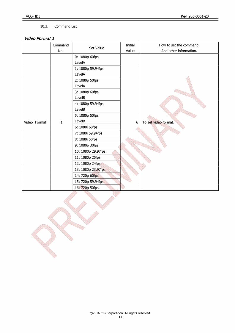
10.3. Command List
Video Format 1
Command
No. Set Value
Initial
Value
How to set the command.
And other information.
Video Format 1
0: 1080p 60fps
LevelA
6 To set video format.
1: 1080p 59.94fps
LevelA
2: 1080p 50fps
LevelA
3: 1080p 60fps
LevelB
4: 1080p 59.94fps
LevelB
5: 1080p 50fps
LevelB
6: 1080i 60fps
7: 1080i 59.94fps
8: 1080i 50fps
9: 1080p 30fps
10: 1080p 29.97fps
11: 1080p 25fps
12: 1080p 24fps
13: 1080p 23.97fps
14: 720p 60fps
15: 720p 59.94fps
16: 720p 50fps
VCC-HD3 Rev. 905-0051-Z0
©2016 CIS Corporation. All rights reserved. 12
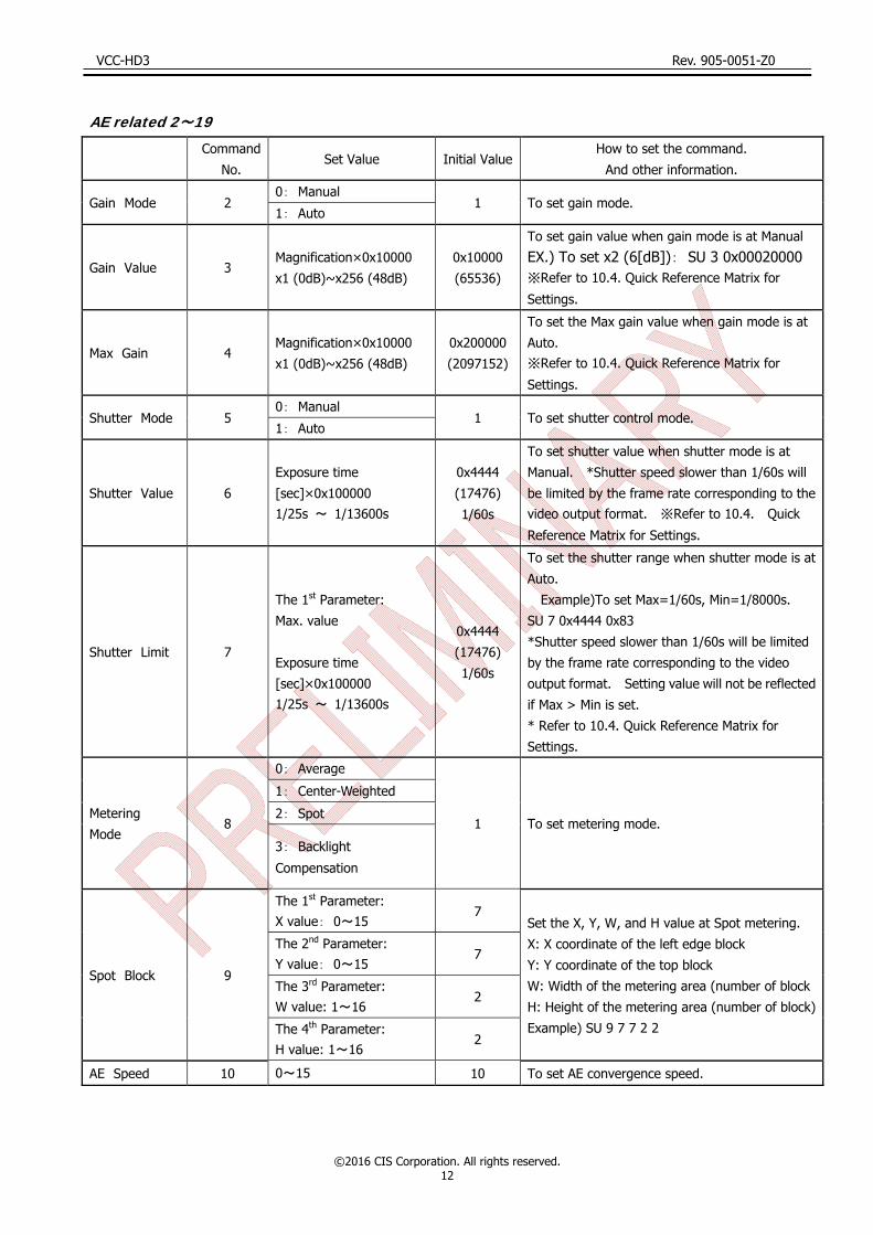
AE related 2~19
Command
No. Set Value Initial Value
How to set the command.
And other information.
Gain Mode 2 0: Manual
1 To set gain mode. 1: Auto
Gain Value 3 Magnification×0x10000
x1 (0dB)~x256 (48dB)
0x10000
(65536)
To set gain value when gain mode is at Manual EX.) To set x2 (6[dB]): SU 3 0x00020000 ※Refer to 10.4. Quick Reference Matrix for
Settings.
Max Gain 4 Magnification×0x10000
x1 (0dB)~x256 (48dB)
0x200000
(2097152)
To set the Max gain value when gain mode is at
Auto. ※Refer to 10.4. Quick Reference Matrix for
Settings.
Shutter Mode 5 0: Manual
1 To set shutter control mode. 1: Auto
Shutter Value 6
Exposure time
[sec]×0x100000 1/25s ~ 1/13600s
0x4444
(17476)
1/60s
To set shutter value when shutter mode is at
Manual. *Shutter speed slower than 1/60s will
be limited by the frame rate corresponding to the video output format. ※Refer to 10.4. Quick
Reference Matrix for Settings.
Shutter Limit 7
The 1st Parameter:
Max. value
Exposure time
[sec]×0x100000 1/25s ~ 1/13600s
0x4444
(17476)
1/60s
To set the shutter range when shutter mode is at
Auto.
Example)To set Max=1/60s, Min=1/8000s.
SU 7 0x4444 0x83
*Shutter speed slower than 1/60s will be limited
by the frame rate corresponding to the video
output format. Setting value will not be reflected
if Max > Min is set.
* Refer to 10.4. Quick Reference Matrix for
Settings.
Metering
Mode 8
0: Average
1 To set metering mode.
1: Center-Weighted
2: Spot
3: Backlight
Compensation
Spot Block 9
The 1st Parameter: X value: 0~15
7 Set the X, Y, W, and H value at Spot metering.
X: X coordinate of the left edge block
Y: Y coordinate of the top block
W: Width of the metering area (number of block
H: Height of the metering area (number of block)
Example) SU 9 7 7 2 2
The 2nd Parameter: Y value: 0~15
7
The 3rd Parameter: W value: 1~16
2
The 4th Parameter: H value: 1~16
2
AE Speed 10 0~15 10 To set AE convergence speed.

VCC-HD3 Rev. 905-0051-Z0
©2016 CIS Corporation. All rights reserved. 13
Command
No. Set Value Initial Value
How to set the command.
And other information.
Exposure
Compensation
Value
11 0(-18dB)~18(0dB)~36
(18dB)/per 1dB 18 To set exposure compensation value..
Flicker Cancel 12 0: OFF
0 To set flicker cancel, ON/OFF. 1: ON
Gain Value,
Plus Minus 13
-1
None
Lower the gain value by 1dB from the current
one. Valid when Gain Mode is at Manual.
(Write only)
1
Raise the gain value by 1dB from the current
one. Valid when Gain Mode is at Manual.
(Write only)
Shutter Value,
Plus Minus 14
-1
None
Lower the shutter speed by 1 step (1/4EV) from
the current one. (Shutter value becomes
bigger.) Valid when Shutter Mode is at Manual. (Write only) ※Note 1
1
Raise the shutter speed by 1 step (1/4EV) from
the current one. (Shutter value becomes
smaller.) Valid when Shutter Mode is at Manual. (Write only) ※Note 1
※Note 1: There may be error (small differences) between the set shutter value and the actual shutter value. For the actual
shutter value, please refer to Section 10.4.3. Actual Shutter Value limited by output format.

VCC-HD3 Rev. 905-0051-Z0
©2016 CIS Corporation. All rights reserved. 14
WB related 20~29
Command
No. Set Value
Initial
Value
How to set the command.
And other information.
WB Mode 20
0: Auto
0 To set white balance mode.
1: Auto (Outdoor)
2: DayLight (Sunlight)
3: Cloudy
4: Shade
5: Tungsten (Light bulb)
6: Flw
(Fluorescent light White)
7: Fln
(Fluorescent light noon/daytime White))
8: Fld
(Fluorescent light daylight)
9: Auto(ATW)
10: OnePush
11: Manual
12: Preset1
13: Preset2
14: Preset3
15: Preset4
16: Preset5
Preset 21
1: Preset1
None
(Write Only)
Store the current WB value as a preset value.
Stored value will not be saved unless otherwise
executing SAVE.
2: Preset2
3: Preset3
4: Preset4
5: Preset5
Blue Gain 22 0~800(%) 161 To set B gain when WB mode is at Manual.
Red Gain 23 0~800(%) 220 To set R gain when WB mode is at Manual.
One Push
Trigger 24 1: Trigger Start None
(Write Only)
To start operation when WB mode is at One
Push.

VCC-HD3 Rev. 905-0051-Z0
©2016 CIS Corporation. All rights reserved. 15
Image Quality related 30~59
Command
No. Set Value Initial Value
How to set the command.
And other information.
Edge Level 30
0: Off
2 To set the level of edge
1:1
2:2
3:3
4:4
5:5
6:6
7:7
Contrast / D-Range 35
0: Contrast -2
2
To set contrast and dynamic range0~4:Dynamic range remains as
the standard but contrast changes.
5: Dynamic range becomes double
of the standard. This is effective
to shoot an image with big
differences between light and dark
part (big contrast). Contrast
would be as the standard.
※ When D-range extension is
selected, the minimum Gain value
with GU 3 command shall be 6dB.
1: Contrast -1
2: Standard
3: Contrast +1
4: Contrast +2
5: D-range Extension
Master Pedestal 37 -100~+100 0 To set master pedestal.
Red Pedestal 38 -100~+100 0 To set Red pedestal.
Green Pedestal 39 -100~+100 0 To set Green pedestal.
Blue Pedestal 40 -100~+100 0 To set Blue pedestal.
Red Balance 41 0~200 100 To set Red balance.
Green Balance 42 0~200 100 To set Green balance.
Blue Balance 43 0~200 100 To set Blue balance.
Color Saturation 45 0~200 100 To set color saturation control.
Noise Reduction 50 0 : Noise reduction OFF
1 : Noise reduction ON 0 To set the Noise Reduction.
Color Correction 52
0: Standard
0 To set color correction. 1: Fluorescent light
2: Tungsten lamp
Color Suppression 53 0~7 5 To set color suppression.
Lens Control related 60~
Command
No. Set Value Initial Value
How to set the command.
And other information.
Iris Mode 61
0: OPEN
0
To set Iris control mode.
Set to AUTO when a DC Iris Lens is
in use. 1: Auto

VCC-HD3 Rev. 905-0051-Z0
©2016 CIS Corporation. All rights reserved. 16
OSD related 90~
Command No. Set Value Initial ValueHow to set the command.
And other information.
OSD UP button 90 0: One push
None
Command to operate OSD.
With continuous push operation,
send the command every 60msec.
1: Continuous push
OSD DOWN button 91 0: One push
None 1: Continuous push
OSD R button 92 0: One push
None 1: Continuous push
OSD L button 93 0: One push
None 1: Continuous push
OSD CENTER button 94 0: One push
None Use as a Set button. 1: Continuous push
Menu Color 95
0: Black
1: Blue
2: Green
3: Cyan
4: Red
5: Magenta
6: Yellow
7: White
7 To set the font color of OSD.
Select Color 96
0: Black
1: Blue
2: Green
3: Cyan
4: Red
5: Magenta
6: Yellow
7: White
3
To set the selected letter’s font
color of OSD.
If the same color as the menu
color is specified, it will be an error,
because the selected letters
cannot be recognized.

VCC-HD3 Rev. 905-0051-Z0
©2016 CIS Corporation. All rights reserved. 17
Others in 100s
Command
No. Set Value Initial Value
How to set the command.
And other information.
Camera Setting
Store 100 0~3 Initial is 0
4 kinds of camera settings can be
stored.
The stored values cannot be saved
until SAVE command is executed.
The stored data and set values will
not be initialized by executing INIT
command.
Camera Setting
Load 101 0~3 Initial is 0
To reflect the stored setting values
set by Camera Setting Store,
to the camera.
The set value will not be initialized
by executing INIT command.
*When Camera Setting Store is
executed, the setting values
forcibly become the one set by
Camera Setting Store.
LTC OFF/ON 103 0: OFF
0 To set LTC signals OFF/ON. 1: ON
LTC Reset 104 1: Reset
(Write Only)
To reset the internal free-running
timer of LTC.
No Command Numbers
Command
No. Set Value Initial Value
How to set the command.
And other information.
SAVE None None None
To save camera settings.
SAVE with capital letters.
*As to pixel defects correction, only
one table can be saved.
INIT None None None To initialize the camera settings.
INIT with capital letters.
GVI None 1: Microcomputer’s version
2: FPGA’s version None
To acquire the firmware’s version.
The letter strings such as 0.1 shall be
responded.
SDDW None 512 0
To start detection of pixel defects
Please refer to the Section 9,
Defective Pixel Correction, for the
details.
VCC-HD3 Rev. 905-0051-Z0
©2016 CIS Corporation. All rights reserved. 18
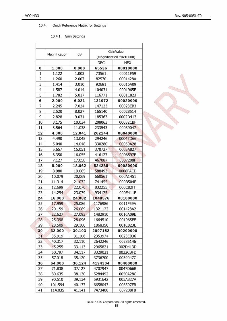
10.4. Quick Reference Matrix for Settings
10.4.1. Gain Settings
Magnification dB GainValue
(Magnification *0x10000)
DEC HEX 0 1.000 0.000 65536 00010000 1 1.122 1.003 73561 00011F59 2 1.260 2.007 82570 0001428A 3 1.414 3.010 92681 00016A09 4 1.587 4.014 104031 0001965F 5 1.782 5.017 116771 0001C823 6 2.000 6.021 131072 00020000 7 2.245 7.024 147123 00023EB3 8 2.520 8.027 165140 00028514 9 2.828 9.031 185363 0002D413 10 3.175 10.034 208063 00032CBF 11 3.564 11.038 233543 00039047 12 4.000 12.041 262144 00040000 13 4.490 13.045 294246 00047D66 14 5.040 14.048 330280 00050A28 15 5.657 15.051 370727 0005A827 16 6.350 16.055 416127 0006597F 17 7.127 17.058 467087 0007208F 18 8.000 18.062 524288 00080000 19 8.980 19.065 588493 0008FACD 20 10.079 20.069 660561 000A1451 21 11.314 21.072 741455 000B504F 22 12.699 22.076 832255 000CB2FF 23 14.254 23.079 934175 000E411F 24 16.000 24.082 1048576 00100000 25 17.959 25.086 1176986 0011F59A 26 20.159 26.089 1321122 001428A2 27 22.627 27.093 1482910 0016A09E 28 25.398 28.096 1664510 001965FE 29 28.509 29.100 1868350 001C823E 30 32.000 30.103 2097152 00200000 31 35.919 31.106 2353974 0023EB36 32 40.317 32.110 2642246 00285146 33 45.255 33.113 2965821 002D413D 34 50.797 34.117 3329021 0032CBFD 35 57.018 35.120 3736700 0039047C 36 64.000 36.124 4194304 00400000 37 71.838 37.127 4707947 0047D66B 38 80.635 38.130 5284492 0050A28C 39 90.510 39.134 5931642 005A827A 40 101.594 40.137 6658043 006597FB 41 114.035 41.141 7473400 007208F8

VCC-HD3 Rev. 905-0051-Z0
©2016 CIS Corporation. All rights reserved. 19
10.4.2. Shutter Settings
Exposure Time
(sec)
ShutValue(sec*0x100000)
DEC HEX 1/25 41943 0000A3D7 1/30 34952 00008888 1/60 17476 00004444 1/90 11650 00002D82
1/100 10485 000028F5 1/125 8388 000020C4 1/180 5825 000016C1 1/250 4194 00001062 1/350 2995 00000BB3 1/500 2097 00000831 1/725 1446 000005A6 1/1000 1048 00000418 1/1500 699 000002BB 1/2000 524 0000020C 1/3000 349 0000015D 1/4000 262 00000106 1/6000 174 000000AE 1/8000 131 00000083 1/9600 109 0000006D 1/11200 94 0000005E 1/13600 77 0000004D
Magnification dB
GainValue
(Magnification *0x10000)
DEC HEX 42 128.000 42.144 8388608 00800000 43 143.675 43.148 9415894 008FACD6 44 161.270 44.151 10568984 00A14518 45 181.019 45.154 11863283 00B504F3 46 203.187 46.158 13316085 00CB2FF5 47 228.070 47.161 14946800 00E411F0 48 251.189 48.000 16461899 00FB304B

VCC-HD3 Rev. 905-0051-Z0
©2016 CIS Corporation. All rights reserved. 20
10.4.3. Actual Shutter Value limited by output format
Set Value
Shutter Value
Actual Shutter Value 60fps 59.94fps 50fps 30fps 29.97fps 25fps 24fps 23.976fps
1/4000 262 1/3988 1/3984 1/4084 1/3988 1/3984 1/3808 1/4238 1/4234 1/4800 218 1/4847 1/4842 1/4778 1/4522 1/4518
1/5222 1/5027 1/5023
1/5600 187 1/5660 1/5654 1/5756 1/5222 1/52171/6177 1/6172
1/6800 154 1/6800 1/6794 1/72371/7562 1/7555
1/6412 1/8000 131 1/7562 1/8508 1/8306
1/8306 1/8010 1/8003
1/9600 109 1/9745 1/9736 1/97451/9745 1/9736
1/11389 1/113791/11200 94 1/11389 1/11379 1/117871/11787
1/13600 77 1/13701 1/13690 1/14911 1/13701 1/13689

VCC-HD3 Rev. 905-0051-Z0
©2016 CIS Corporation. All rights reserved. 21
11. How to Operate the Camera with OSD Function
You can operate the camera with OSD menu on a monitor screen by connecting an optional remote controller to the
camera remote controller terminal.
11.1. Switch Operation of OSD Menu by Remote Controller
[CENTER]: To indicate OSD top menu on your monitor screen when it is not shown. And, it is also used to settle
the selected menu.
[] Go up the selected item by one.
[] Go down the selected item by one.
[ ] Change the options.
[ ] Change the options.
11.2. Indication of OSD Menu
Menu with at the line end indicates that submenu can be opened with the CENTER button.
Menu with at the line head indicates that the item is settled with the CENTER button.
11.3. OSD Menu
Top Menu Setting Menu Selected Items Explanation
EXIT None None Push the CENTER button to close OSD menu.
Output Format Set Video Format
1080p 60fps
(Level A)
To set video format.
Select video format with / button,
then push the CENTER button to confirm.
1080p 59.94fps
(Level A)
1080p 50fps
(Level A)
1080p 60fps
(Level B)
1080p 59.94fps
(Level B)
1080p 50fps
(Level B)
1080i 60fps
1080i 59.94fps
1080i 50fps
1080p 30fps
1080p 29.97fps
1080p 25fps
1080p 24fps
1080p 23.97fps
720p 60fps
720p 59.94fps
720p 50fps

VCC-HD3 Rev. 905-0051-Z0
©2016 CIS Corporation. All rights reserved. 22
Top Menu Setting Menu Selected Items Explanation
Gain/Shutter/IRIS
Gain Mode Manual/Auto To set Gain Mode.
Gain Value 0~48dB To set the Gain Value when Gain Mode is at Manual. ※Note 1/ ※Note 2
Gain Max Value 0~48dB To set the Max Gain Value when Gain Mode is at Auto. ※Note 1/※Note 2
Shutter Mode Manual/Auto To set Shutter Mode.
Shutter Value
1/25
To set the Shutter Value when Shutter Mode is
at Manual.
Shutter speed lower than 1/60 shall be limited by
the frame rate correspond to the video output
format.
※Note 1
※Note 2
※Note 3
1/30
1/36
1/42
1/50
1/60
1/75
1/90
1/100
1/105
1/120
1/125
1/150
1/180
1/210
1/250
1/300
1/350
1/420
1/500
1/600
1/700
1/840
1/1000
1/1200
1/1400
1/1700
1/2000
1/2400
1/2800
1/3400
1/4000
1/4800
1/5600
1/6800
1/8000
1/9600
1/11200
1/13600
VCC-HD3 Rev. 905-0051-Z0
©2016 CIS Corporation. All rights reserved. 23
Top Menu Setting
Menu
Selected
Items Explanation
Gain/Shutter/IRIS
Shutter Min
Limit
Same as
Shutter Value
To set the Minimum Shutter Limit when Shutter Mode is at Auto. ※Note 1/※Note 2
Shutter Max
Limit
Same as
Shutter Value
To set the Maximum Shutter Limit when Shutter Mode is at Auto. ※Note 1/※Note 2
Set Shutter
Limit None
Push the CENTER button to settle the shutter limit.
When Max < Min is set, the setting will not be valid.
AE Speed 0~15 To set AE convergence speed.
ExpCompValue -18~0~18
[dB] To set Exposure Compensation Value.
Metering Mode
Average To set metering mode. Average:Averaging metering
Center Weighted:Center weighted metering
Spot:Spot metering
Backlight Compensation: Backlight compensation metering
Center
Weighted
Spot
Backlight Comp
Spot Block X 0~15 To select the X coordinate value of the Left edge Block of the metering area when Metering Mode is set to “Spot”.
Spot Block Y 0~15 To select the Y coordinate value of the Top Block of the metering area when Metering Mode is set to “Spot”.
Spot Block W 1~16 To select the width (Block number) of the metering area when Metering Mode is set to “Spot”.
Spot Block H 1~16 To select the height (Block number) of the metering area when Metering Mode is set to “Spot”.
Set Spot Block None Push the CENTER button to confirm Spot Block, X, Y, W,
and H.
Flicker Cancel ON/OFF To set flicker cancel.
※Note 1: If you prefer setting further details, please set them via serial commands.
※Note 2: The values set via serial commands will be reflected to key operation.
※Note 3: There may be error (small differences) between the set shutter value and the actual shutter value. For the actual shutter value, please refer to Section 10.4.3. Actual Shutter Value limited by output format.

VCC-HD3 Rev. 905-0051-Z0
©2016 CIS Corporation. All rights reserved. 24
Top Menu Setting Menu Selected Items Explanation
White Balance
WB Mode
Auto
Select and set WB Mode with /
button.
Outdoor
Daylight
(Sun light)
Cloudy
Shade
Tungsten
Flw
(Fluorescent White)
Fln (Fluorescent noon white)
Fld (Fluorescent day light)
Auto(ATW)
One push
Manual
Preset1
Preset2
Preset3
Preset4
Preset5
WB Red
Gain 0~800
To set Red Gain/Blue Gain when WB Mode
is at Manual. WB Blue
Gain 0~800
One Push
Start None
Valid only when WB mode is at One Push.
Execute One Push WB with the CENTER
button.
Set Preset
Number 1~5
Select the preset number with the
/ button, and push the CENTER
button to save the current WB value.

VCC-HD3 Rev. 905-0051-Z0
©2016 CIS Corporation. All rights reserved. 25
Top Menu Setting Menu Selected
Items Explanation
Image Control
Red Balance 50~150 To set Red Balance. ※Note 3
Green Balance 50~150 To set Green Balance. ※Note 3
Blue Balance 50~150 To set Blue Balance. ※Note 3
Master Pedestal -100~100 To set Master Pedestal.
Red Pedestal -100~100 To set Red Pedestal.
Green Pedestal -100~100 To set Green Pedestal.
Blue Pedestal -100~100 To set Blue Pedestal.
Edge Level 0~7 To set the edge enhancement Level. 0 is OFF.
Contrast
Contrast -2
To set Contrast and Dynamic range.
When D-range Ext is selected, dynamic range will be
double of the standard. (Contrast remains as standard
level).
Contrast -1
Standard
Contrast +1
Contrast +2
D-range Ext
Noise
Reduction OFF/ON
To set Noise Reduction
Noise reduction OFF/ON. Color
Saturation 0~200 To set color saturation.
Color
Correction
Standard
To set color correction. Fluorescent
light
Tungsten lamp
Color
Suppression 0~7 To set color suppression.
LTC LTC ON/OFF LTC ON/OFF.
Set LTC Reset None To reset LTC with the CENTER button.
※Note 3:The values 0~200 can be set via serial command.

VCC-HD3 Rev. 905-0051-Z0
©2016 CIS Corporation. All rights reserved. 26
Top Menu Setting Menu Selected
Items Explanation
OSD Color Change
Default Set
(White & Cyan) None
To get the OSD color back to the default setting with the
CENTER button.
User Setting To set the color to display the OSD menu.
Menu Color
Black
To select the color to display the OSD menu with the
/ button.
Blue
Green
Cyan
Red
Magenta
Yellow
White
Highlight Color Same as
Menu Color
To select the highlight color to display on the OSD menu
with the / button.
Set Color None
Confirm the menu color and the highlight color with the
CENTER button.
When the same colors are specified for both menu color
and highlight color, they will not be settled.
INIT None None To get the camera settings back to the initial settings
with the CENTER button.
Save/Load
Set Save Data 0~3 To save the data to the preset number selected, with
the CENTER button.
Really? NO/YES To make sure if you really want to save the data to the
selected preset.
Enter None To execute SAVE or NOT SAVE, then get back to the
original screen.
Get Save Data 0~3 To call up the data of the selected preset number and
reflect it on the screen with the CENTER button.
VCC-HD3 Rev. 905-0051-Z0
©2016 CIS Corporation. All rights reserved. 27
12. Factory Settings
Function Default Settings
Video Format Setting 1920 x 1080i @60fps
Gain Mode Auto
Gain Value (Manual Gain) 65536(0dB)
Max Gain 16461899 (48dB)
Shutter Mode Auto
Shutter Limit Max 17476(1/60s)
Shutter Limit Min 77(1/13600s)
Shutter Value (Manual Shutter) 17476(1/60s)
Metering Mode Center-Weight
Spot Block X=7,Y=7, W=2, H=2
Exposure Compensation Value 18 (0dB)
AE Speed 10
Flicker Cancel OFF
White Balance Setting Auto
Manual Red Gain 220
Manual Blue Gain 161
Color Correction Standard
Color Suppression 5
Color Saturation 100
Edge Enhancement 2
Noise Reduction 0
Contrast Standard
Master Pedestal 0
Pedestal(RGB) 0
Color Balance (RGB) 100
LTC OFF
OSD Menu Color White
OSD Select Color Cyan

VCC-HD3 Rev. 905-0051-Z0
©2016 CIS Corporation. All rights reserved. 28
13. Dimensions
*2-M3 Depth from the surface is 4mm. However, there is no screw thread up to 1mm from the surface.
935-XXXX-00-00 (Unit:)

VCC-HD3 Rev. 905-0051-Z0
©2016 CIS Corporation. All rights reserved. 29
14. Cases for Indemnity (Limited Warranty)
The term of warranty of this product is within 1.5 years from the date of shipping out from our factory.
If you use the product properly and discover a defect during the warranty period, and if that was caused by
designing or manufacturing, CIS Corporation, at its option, repairs or replaces it at no charge to you.
Products out of warranty period will be subject to charge. CIS repairs the products as long as it is repairable.
CIS shall be exempted from taking responsibility and held harmless for damages or losses incurred by the
following cases.
In case damages or losses are caused by earthquake, lightning strike, fire, or other acts of God.
In case damages or losses are caused by deliberate or accidental misuse by the user, or failure to observe
the information contained in the instructions in this Product Specification and Operational Manual.
In case damages or losses are caused by repair or modification conducted by the customer or any
unauthorized party.
15. CMOS Pixel Defect
CIS compensates the noticeable CMOS pixel defects found at the shipping inspection prior to our shipment.
On very rare occasions, however, CMOS pixel defects might be noted with time of usage of the products.
Cause of the CMOS pixel defect is the characteristic phenomenon of CMOS sensor itself and CIS is exempted
from taking any responsibilities for them. Should you have any questions on CMOS pixel defects compensation
please contact us.
16. Product Support
Should you have any problems in function of the product you purchased, and if you need our further analysis
and/or repair, please contact the dealer you purchased it from.
Camera Control Sample Software is downloadable via our web but we shall be exempted from taking
responsibility and held harmless for damage or malfunction of your hardware and software caused by using this
control software.
The purpose of the control software prepared is for you to check operation and evaluate our products.
Please be noted that CIS does not customize the program nor provide source code.
URL: http://www.ciscorp.co.jp/support_en.php