presentation variable speed drives for … 31...presentation variable speed drives for asynchronous...
TRANSCRIPT

2
Presentation Variable speed drivesfor asynchronous motors 2
Altivar 31
ESC
ENT
RUNFWO
REV
stopreset
1
34
5
6
7
2

3
Presentation (continued) Variable speed drivesfor asynchronous motors 2
Altivar 31
The Altivar 31 drive is a frequency inverter for 3-phase squirrel cage asynchronous motors. The Altivar 31 is robust, compact, easy to use and conforms to EN 50178, IEC/EN 61800-2, IEC/EN 61800-3 standards, UL/CSA certification and to � marking.
It incorporates functions that are suitable for the most common applications, including:� Materials handling (small conveyors, hoists, etc.),� Packing and packaging machines,� Specialist machines (mixers, kneaders, textile machines, etc.),� Pumps, compressors, fans.
Altivar 31 drives communicate on Modbus and CANopen industrial buses. These two protocols are integrated as standard into the drive.
Altivar 31 drives are supplied with a heatsink for normal environments and ventilated enclosures. Multiple units can be mounted side by side 3 to save space.
Drives are available for motor ratings between 0.18 kW and 15 kW, with four types of power supply:� 200 V to 240 V single phase, 0.18 kW to 2.2 kW� 200 V to 240 V 3-phase, 0.18 kW to 15 kW� 380 V to 500 V 3-phase, 0.37 kW to 15 kW� 525 V to 600 V 3-phase, 0.75 kW to 15 kW
Altivar 31 drives are available with a choice of two different human-machine interfaces:� 1 ATV 31H�����with displays and menu navigation keys � 2 ATV 31H����A with�displays, menu navigation keys and local control (Run/Stop and speed reference set by a potentiometer).
Electromagnetic compatibility EMCThe incorporation of level A EMC filters (conducted and radiated) in ATV 31H��M2and ATV 31H��N4 drives simplifies the installation of machines and provides an economical means of meeting � marking requirements.ATV 31H��M3X and ATV 31H��S6X drives are available without EMC filter. Filters are available as an option for customer assembly, if conformity to EMC standards is required.
The Altivar 31 drive has six logic inputs, three analog inputs, one logic/analog output and two relay outputs.The main functions integrated in the drive are as follows:� Motor and drive protection� Linear, S, U and customised acceleration and deceleration ramps� +/- speed� 16 preset speeds� PI references and regulator� 2-wire/3-wire control� Brake sequence� Automatic catching a spinning load with speed detection and automatic restart� Fault configuration and stop type configuration� Saving the configuration in the driveSeveral functions can be assigned to one logic input.
The following options and accessories can be used with the Altivar 31 drive:� Braking resistors� Line chokes� EMC radio interference input filters and output filters� Plates for mounting on � rail� UL Type 1 conformity kit� Adaptor plate for replacing an Altivar 28 drive
Various dialogue and communication options 4, 5, 6, 7 can be used with the drive, see pages 7 and 8.
Applications
Functions
Options and accessories
Characteristics:pages 10 to 13
References:pages 14 to 17
Dimensions:pages 30 to 35
Schemes:pages 36 to 39
Functions:pages 44 to 59

4
Presentation Variable speed drivesfor asynchronous motors 2
Altivar 31Enclosed drive
ESC
ENT
RUNFWO
REV
stopreset
1
2
3
4
5

5
Presentation (continued) Variable speed drivesfor asynchronous motors 2
Altivar 31Enclosed drive
The enclosed Altivar 31 drive is suitable for applications requiring:- IP 55 degree of protection in a hostile environment- a drive that is ready for use in a motor starter
Once it has been customised, the enclosure can be installed next to the motor.Enclosed drives are available in power ratings from 0.18 kW to 4 kW.There are two types of power supply:� 200 V to 240 V single phase, 0.18 kW and 2.2 kW� 380 V to 500 V 3-phase, 0.37 kW and 4 kW
This range allows full customisation of the human-machine interface of an enclosure. The IP 55 enclosure includes:� a drive with external heatsink� removable covers for installation of the following components:7 Vario switch disconnector or GV2 circuit-breaker8 3 buttons and/or LEDs with plastic flange Ø 22, and 1 speed reference potentiometer9 button for the RJ45 connector with IP 55 cable10 cable glands for cable routing
The combinations (drive, circuit-breaker, contactor) required for the motor starter function can be found on pages 40 and 41. Example references:
- 3-pole Vario switch disconnector (V�� + KC� 1�Z)- Selector switch with 3 fixed positions XB5 D33- LED XB5 AV��- 2.2 kOhm potentiometer
These references can be found in our specialist catalogues.All components must be ordered separately and wired by the customer.
Electromagnetic compatibility EMCThe incorporation of level A EMC filters (conducted and radiated) in ATV 31C��M2and ATV 31C��N4 drives simplifies the installation of machines and provides an economical means of meeting � marking requirements.
The following options and accessories can be used with the enclosed Altivar 31 drive:� Braking resistors� Line chokes� RJ45 connector with IP 55 cable
Various dialogue and communication options 2, 3, 4, 5 can be used with the drive, see pages 7 and 8.
Applications
10
9
7
8
Customisable enclosed drive
Options and accessories
Characteristics:pages 10 to 13
References:pages 14 to 17
Dimensions:pages 30 to 35
Schemes:pages 36 to 39
Functions:pages 44 to 59

6
Presentation Variable speed drivesfor asynchronous motors 2
Altivar 31Drive kit
ESC
ENT
RUNFWO
REV
stopreset
4
2
9
10
11
12
1
5
8 7 4 3 6
3 2

7
Presentation (continued) Variable speed drivesfor asynchronous motors 2
Altivar 31Drive kit
The drive kit is a new addition to the Altivar 31 drives range.The drive kit comprises:� Altivar 31 drive elements (heatsink, power and control subassemblies)� EMC filter� Mechanical fittings� Seals required for use in difficult environments (IP 55)The kit is mounted on a metal fixing support with no flange or protective cover.The Altivar 31 drive kit can be built into a floor-standing or wall-mounted enclosure or a machine frame.
The drive kit is available for power ratings from 0.18 kW to 15 kW.There are two types of power supply:� 200 V to 240 V single phase, 0.18 kW to 2.2 kW� 380 V to 500 V 3-phase, 0.37 kW to 15 kW
Electromagnetic compatibility EMCThe incorporation of level A EMC filters (conducted and radiated) in ATV 31K��M2and ATV 31K��N4 drives simplifies the installation of machines and provides an economical means of meeting � marking requirements. The drives have been sized to conform to the following standards: IEC/EN61800-3, domestic and industrial environments.
� Drive kit for power ratings � 4 kW 1The Altivar 31 drive components (heatsink, power and control subassemblies) are fixed by mechanical adaptors 2 and protective fittings.The unit is supported by a metal plate 3 fixed to the heatsink.The plate is sealed on all sides.Once the support has been cut out, the drive kit is fixed to the base of the floor-standing or wall-mounted enclosure by means of this plate.The power terminals 5 are protected (IP 20).
� Drive kit for power ratings � 5.5 kW 6The Altivar 31 drive components (heatsink, power and control subassemblies) are fixed by mechanical adaptors 2 and protective fittings.The metal support plate 3 for the components is fitted with brackets 8 for mounting in a floor-standing or wall-mounted enclosure. The plate is sealed on all sides 4.Two fans are fitted behind the plate under the heatsink.Additional fixing holes 7 are provided for component mounting (GV2 circuit-breaker, Vario switch disconnector, additional plate, etc.).
Drive kits are supplied with:� A drilling and cutting template to assist with installation� A user’s manual with installation instructions and safety precautions.
The following options and accessories can be used with the Altivar 31 drive kit:� Braking resistors� Line chokes
Various dialogue and communication options 9, 10, 11, 12 can be used with the drive, see pages 7 and 8.
Applications
Description
Options and accessories
Characteristics:pages 10 to 13
References:pages 14 to 17
Dimensions:pages 30 to 35
Schemes:pages 36 to 39
Functions:pages 44 to 59

8
Presentation Variable speed drivesfor asynchronous motors 2
Altivar 31Dialogue options
The Altivar 31 drive communicates with the following options:� Remote terminal� PowerSuite software workshop� Ethernet/Modbus bridge� Communication gateways
The communication function provides access to the drive’s configuration, adjustment, control and signalling functions.
The Altivar 31 can be connected to a remote terminal.The remote terminal can be mounted on the door of an enclosure with IP 65 protection on the front panel.The terminal provides access to the same functions as the display and integral keys on the drive (see page 45).
It can be used:� to control, adjust and configure the drive remotely � for visible remote signalling� to save and download configurations (4 configuration files can be saved)
Description1 Display�Four 7-segment displays visible at 5 m�Displays numeric values and codes�The display flashes when a value is stored.�The display flashes to indicate a fault on the drive.
2 Use of keys:�Navigation arrows and ENT, ESC for settings and configurations�FWD/REV key: reverses the direction of rotation of the motor�RUN key: motor run command�STOP/RESET key: motor stop command or drive fault reset
Remote terminal
ESC
ENT
RUNFWO
REV
stopreset
1
2
5632
20
Characteristics:pages 10 to 13
References:pages 14 to 17
Dimensions:pages 30 to 35
Schemes:pages 36 to 39
Functions:pages 44 to 59

9
Presentation Variable speed drivesfor asynchronous motors 2
Altivar 31Communication options
PowerSuite advanced dialogue solutions offer the following advantages:� Display messages in plain text and multiple languages� Prepare work in design office without connecting the Altivar to the PC� Save configurations and settings to floppy disk or hard disk and download them to the drive� Print out settings � Read and import Altivar 28 files into the Altivar 31.
See pages 28 and 29.
The Altivar 31 can be connected to an Ethernet network via an Ethernet/Modbus bridge.Ethernet communication is primarily intended for the following applications:� Coordination between PLCs� Local or centralised supervision� Communication with production management software� Communication with remote I/O� Communication with industrial control products
See pages 26 and 27.
The Altivar 31 can connect to other communication buses by means of the following gateways:� Fipio/Modbus,� DeviceNet/Modbus� Profibus DP/Modbus
See pages 26 and 27.
PowerSuite software workshop
Ethernet/Modbus bridge
Communication gateways
5630
19
174 CEV 300 10
5630
16
LUF P1
LA9 P307
5630
18
Characteristics:pages 10 to 13
References:pages 14 to 17
Dimensions:pages 30 to 35
Schemes:pages 36 to 39
Functions:pages 44 to 59
5630
17
10
Characteristics Variable speed drivesfor asynchronous motorsAltivar 31
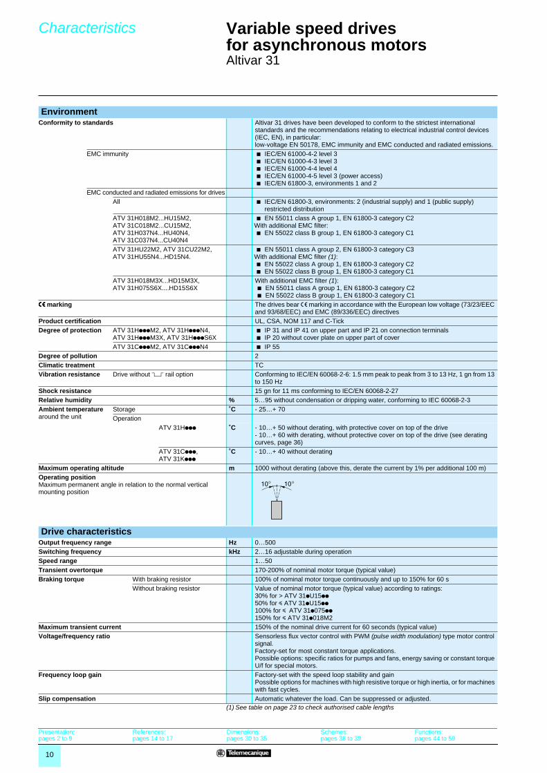
(1) See table on page 23 to check authorised cable lengths
EnvironmentConformity to standards Altivar 31 drives have been developed to conform to the strictest international
standards and the recommendations relating to electrical industrial control devices (IEC, EN), in particular:low-voltage EN 50178, EMC immunity and EMC conducted and radiated emissions.
EMC immunity b IEC/EN 61000-4-2 level 3b IEC/EN 61000-4-3 level 3b IEC/EN 61000-4-4 level 4b IEC/EN 61000-4-5 level 3 (power access)b IEC/EN 61800-3, environments 1 and 2
EMC conducted and radiated emissions for drivesAll b IEC/EN 61800-3, environments: 2 (industrial supply) and 1 (public supply)
restricted distributionATV 31H018M2...HU15M2, ATV 31C018M2...CU15M2, ATV 31H037N4...HU40N4, ATV 31C037N4...CU40N4
b EN 55011 class A group 1, EN 61800-3 category C2With additional EMC filter:b EN 55022 class B group 1, EN 61800-3 category C1
ATV 31HU22M2, ATV 31CU22M2, ATV 31HU55N4...HD15N4.
b EN 55011 class A group 2, EN 61800-3 category C3With additional EMC filter (1):b EN 55022 class A group 1, EN 61800-3 category C2b EN 55022 class B group 1, EN 61800-3 category C1
ATV 31H018M3X...HD15M3X, ATV 31H075S6X....HD15S6X
With additional EMC filter (1):b EN 55011 class A group 1, EN 61800-3 category C2b EN 55022 class B group 1, EN 61800-3 category C1
eeee marking The drives bear e marking in accordance with the European low voltage (73/23/EEC and 93/68/EEC) and EMC (89/336/EEC) directives
Product certification UL, CSA, NOM 117 and C-TickDegree of protection ATV 31HpppM2, ATV 31HpppN4,
ATV 31HpppM3X, ATV 31HpppS6Xb IP 31 and IP 41 on upper part and IP 21 on connection terminalsb IP 20 without cover plate on upper part of cover
ATV 31CpppM2, ATV 31CpppN4 b IP 55Degree of pollution 2Climatic treatment TCVibration resistance Drive without 5 rail option Conforming to IEC/EN 60068-2-6: 1.5 mm peak to peak from 3 to 13 Hz, 1 gn from 13
to 150 HzShock resistance 15 gn for 11 ms conforming to IEC/EN 60068-2-27Relative humidity % 5…95 without condensation or dripping water, conforming to IEC 60068-2-3Ambient temperature around the unit
Storage ˚C - 25…+ 70Operation
ATV 31Hppp ˚C - 10…+ 50 without derating, with protective cover on top of the drive- 10…+ 60 with derating, without protective cover on top of the drive (see derating curves, page 36)
ATV 31Cppp,ATV 31Kppp
˚C - 10…+ 40 without derating
Maximum operating altitude m 1000 without derating (above this, derate the current by 1% per additional 100 m)Operating positionMaximum permanent angle in relation to the normal vertical mounting position
Drive characteristicsOutput frequency range Hz 0…500Switching frequency kHz 2…16 adjustable during operationSpeed range 1…50Transient overtorque 170-200% of nominal motor torque (typical value)Braking torque With braking resistor 100% of nominal motor torque continuously and up to 150% for 60 s
Without braking resistor Value of nominal motor torque (typical value) according to ratings:30% for > ATV 31pU15pp50% for y ATV 31pU15pp100% for y ATV 31p075pp150% for y ATV 31p018M2
Maximum transient current 150% of the nominal drive current for 60 seconds (typical value)Voltage/frequency ratio Sensorless flux vector control with PWM (pulse width modulation) type motor control
signal.Factory-set for most constant torque applications.Possible options: specific ratios for pumps and fans, energy saving or constant torque U/f for special motors.
Frequency loop gain Factory-set with the speed loop stability and gainPossible options for machines with high resistive torque or high inertia, or for machines with fast cycles.
Slip compensation Automatic whatever the load. Can be suppressed or adjusted.
Presentation:pages 2 to 9
References:pages 14 to 17
Dimensions:pages 30 to 35
Schemes:pages 36 to 39
Functions:pages 44 to 59

11
Characteristics (continued) Variable speed drivesfor asynchronous motors 2
Altivar 31
Electrical characteristicsPower supply Voltage V 200 - 15% to 240 + 10% single phase for ATV 31����M2�
200 - 15% to 240 + 10% 3-phase for ATV 31����M3X380 - 15% to 500 + 10% 3-phase for ATV 31����N4�525 - 15% to 600 + 10% 3-phase for ATV 31����S6X
Frequency Hz 50 - 5% to 60 + 5%
Prospective short-circuit current ICC
For drivesATV 31����M2 A ≤ 1000 (ICC at connection point) for single phase power supplyATV 31H018M3X...HU40M3X,ATV 31�037N4...�U40N4,ATV 31H075S6X...HU40S6X
A ≤ 5000 (ICC at connection point) for 3-phase power supply
ATV 31HU55M3X...HD15M3X,ATV 31HU55N4...HD15N4,ATV 31KU55N4...KD15N4,ATV 31HU55S6X...HD15S6X
A ≤ 22000 (ICC at connection point) for 3-phase power supply
Output voltage Maximum 3-phase voltage equal to line supply voltage.Maximum connection capacity and tightening torque of the power supply terminals, motor, braking module and DC bus
For drivesATV 31H018M2...H075M2, ATV 31H018M3X...HU15M3X
2.5 mm2 (AWG 14)0.8 Nm
ATV 31HU11M2...HU22M2, ATV 31HU22M3X...HU40M3X, ATV 31H037N4...HU40N4, ATV 31H075S6X...HU40S6X
5 mm2 (AWG 10)1.2 Nm
ATV 31HU55M3X, HU75M3X, ATV 31HU55N4, HU75N4, ATV 31HU55S6X, HU75S6X
16 mm2 (AWG 6)2.2 Nm
ATV 31HD11M3X, HD15M3X, ATV 31HD11N4, HD15N4, ATV 31HD11S6X, HD15S6X
25 mm2 (AWG 3)4 Nm
Electrical isolation Electrical isolation between power and control (inputs, outputs, power supplies)Internal supplies available Short-circuit and overload protection:
- One +10 V (0/+ 8%) supply for the reference potentiometer (2.2 to 10 kΩ), maximum current 10 mA- One + 24 V supply (min. 19 V, max. 30 V) for logic inputs, maximum current 100 mA
Configurable analog inputs 3 configurable analog inputs AI1, AI2, AI3.� AI1: analog voltage input 0 to +10V, impedance 30 kΩ (maximum safe voltage
30 V)� AI2: analog bipolar voltage input ±10 V, impedance 30 kΩ (maximum safe voltage
30 V)� AI3: analog current input X-Y mA by programming X and Y from 0 to 20 mA, with
impedance 250 ΩAIP: potentiometer reference for ATV31���A onlyMax. sampling time: 8 ms10-bit resolutionPrecision ± 4.3%Linearity ± 0.2% of maximum valueUse:- 100 m maximum with shielded cable- 25 m maximum with unshielded cable
Analog output configurable for voltage, current and logic output
1 analog output configurable for voltage, current.� AOC: analog current output 0 to 20 mA, maximum load impedance 800 Ω� AOV: analog voltage output 0 to +10V, minimum load impedance 470 Ω
8-bit resolutionPrecision ± 1%Linearity ± 0.2% Only analog output AOC is configurable as a logic output.� AOC: operation as logic output 24 V 20 mA max.
Max. sampling time: 8 msConfigurable relay outputs R1A, R1B, R1C 1 relay logic output, one “N/C” contact and one “N/O” contact with common point.
Minimum switching capacity: 10 mA for ��5 V.Maximum switching capacity:� on resistive load (cos ϕ = 1 and L/R = 0 ms): 5 A for � 250 V or � 30 V � on inductive load (cos ϕ = 0.4 and L/R = 7 ms): 2 A for � 250 V or � 30 V
Max. sampling time: 8 msSwitching: 100,000 operations
R2A, R2B 1 relay logic output, one “N/C” contact, contact open on fault.Minimum switching capacity: 10 mA for ��5 V.Maximum switching capacity:� on resistive load (cos ϕ = 1 and L/R = 0 ms): 5 A for � 250 V or � 30 V � on inductive load (cos ϕ = 0.4 and L/R = 7 ms): 2 A for � 250 V or � 30 V
Max. sampling time: 8 msSwitching: 100,000 operations
Presentation:pages 2 to 9
References:pages 14 to 17
Dimensions:pages 30 to 35
Schemes:pages 36 to 39
Functions:pages 44 to 59

12
Characteristics (continued) Variable speed drivesfor asynchronous motors 2
Altivar 31
Electrical characteristics (continued)Logic inputs LI 6 programmable logic inputs
Impedance 3.5 kΩ+ 24 V internal or 24 V external power supply (min. 19 V, max. 30 V)Max. current: 100 mAMax. sampling time: 4 msMultiple assignment makes it possible to configure several functions on one input (example: LI1 assigned to forward and preset speed 2, LI3 assigned to reverse and preset speed 3)
Positive logic State 0 if < 5 V or logic input not wired, state 1 if > 11 VNegative logic State 0 if > 19 V or logic input not wired, state 1 if < 13 VCLI position Connection to PLC output (see diagram page 36)
Maximum I/O connection capacity and tightening torque 2.5 mm2 (AWG 14)0.6 Nm
Acceleration and deceleration ramps Ramp profiles:� linear, can be adjusted separately from 0.1 to 999.9 s� S, U or customised
Automatic adaptation of deceleration ramp time if braking capacities exceeded, possible inhibition of this adaptation (use of braking resistor).
Braking to a standstill By d.c. injection:� by a signal on a programmable logic input� automatically as soon as the estimated output frequency drops to < 0.5 Hz, period
adjustable from 0 to 30 s or continuous, current adjustable from 0 to 1.2 InMain protection and safety features of the drive � Thermal protection against overheating
� Protection against short-circuits between motor phases� Protection against input phase breaks� Protection against motor phase breaks� Protection against overcurrent between output phases and earth� Line supply undervoltage and overvoltage safety circuits� Line supply phase loss safety function, for 3-phase supply
Motor protection(see page 48)
Thermal protection integrated in the drive by continuous calculation of the l2t
Dielectric strength Between earth and power terminals
��2040 V for ATV 31����M2 and M3X, ��2410 V for ATV 31����N4,��2550 V for ATV 31����S6X
Between control and power terminals
��2880 V for ATV 31����M2 and M3X, ��3400 V for ATV 31����N4,��3600 V for ATV 31����S6X
Insulation resistance to earth > 500 M٠(electrical isolation) ��500 V for 1 minuteSignalling 1 red LED on front: LED lit indicates the presence of drive voltage
Display coded by four 7-segment display units displaying the CANopen bus status (RUN and ERR).
Frequency resolution Display units Hz 0.1Analog inputs Hz 0.1 to 100 Hz (calculate (high speed – low speed) /1024)
Time constant for reference change ms 5Communication Modbus and CANopen are integrated into the drive and available via an RJ45
connectorModbus RS 485 multidrop serial link
� Modbus in RTU mode� Services supported: decimal function codes 03, 06, 16, 23 and 43� Broadcasting� Number of addresses: drive address can be configured via the integrated terminal
from 1 to 247� Maximum number of Altivar 31 drives connected: 31 (two 470 Ω master pulldown
resistors) � Transmission speed: 4800, 9600 or 19200 bps
Used for connecting: � the remote terminal (option)� the PowerSuite software workshop� a PLC� a microprocessor card� a PC
CANopen To connect the ATV31 drive on the CANopen bus, use the VW3 CANTAP2 adapter.� Services supported:� Implicit exchange of Process Data Object
- 2 PDOs depending on DSP 402 velocity mode- 2 configurable PDOs (data and transmission type)- PDOs can be exchanged between slaves.� Explicit exchange of Service Data Object
- 1 receive SDO and 1 transmit SDO� Boot-up messages, emergency messages, node guarding and producer and
consumer heartbeat, sync and NMT� Number of addresses: drive address can be configured via the integrated terminal
from 1 to 127� Maximum number of Altivar 31 drives connected: 127� Transmission speed: 10, 20, 50, 125, 250, 500 kbps or 1 Mbps
Presentation:pages 2 to 9
References:pages 14 to 17
Dimensions:pages 30 to 35
Schemes:pages 36 to 39
Functions:pages 44 to 59

13
Characteristics,special uses
Variable speed drivesfor asynchronous motorsAltivar 31
The curves below define the available continuous torque and transient overtorque for both force-cooled and self-cooled motors. The only difference is in the ability of the motor to provide a high continuous torque at less than half the nominal speed
The device can supply any motor which has a power rating lower than that for which it is designed.For motor ratings slightly higher than that of the drive, check that the current taken does not exceed the continuous output current of the drive.
In a testing or maintenance environment the drive can be checked without having to switch to a motor with the same rating as the drive (particularly useful in the case of high power drives). This use requires deactivation of motor phase loss detection.
The rating of the drive must be greater than or equal to the sum of the currents of the motors to be connected to the drive.In this case, external thermal protection must be provided for each motor using probes or LR2 thermal bimetal overload relays designed for a 1.2 In motor.If the number of motors in parallel is greater than or equal to 3, it is advisable to install a 3-phase choke between the drive and the motors.
The drive can be switched when locked or unlocked. If the drive is switched on-the-fly (drive unlocked), the motor is controlled and accelerates until it reaches the reference speed smoothly following the acceleration ramp.This use requires configuration of automatic catching a spinning load (“catch on the fly”) and activation of the function which manages the presence of a downstream contactor.
Example: breaking of downstream contactor
t1: deceleration without ramp (freewheel)t2: acceleration with rampTypical applications: breaking safety circuit at drive outputs, "bypass" function, switching of motors connected in parallel.
(1) For power ratings ≤ 250 W, motor derating is less important (20% instead of 50% at very low frequencies).
(2) The nominal frequency of the motor and the maximum output frequency can be adjusted between 40 and 500 Hz.Note: Check the mechanical overspeed characteristics of the selected motor with the manufacturer.
Torque characteristics (typical curves)
1,71,75
1,50
1,25
2,25
1
2
0,95
0,75
0,50
0,25
00 25/30 50/60 75/90 100/120
1
2
4
3
Hz
1 Self-cooled motor: continuous useful torque (1)2 Force-cooled motor: continuous useful torque3 Transient overtorque 1.7 to 2 Tn4 Torque in overspeed at constant power (2)
Tn
Special usesUse with a motor with a different rating to that of the drive
Test on a low power motor or without a motor
Connecting motors in parallel
Switching the motor at the drive output
N
t1
KM1 0
1
t2
t
t
Altivar 31 M
KM1
Presentation:pages 2 to 9
References:pages 14 to 17
Dimensions:pages 30 to 35
Schemes:pages 36 to 39
Functions:pages 44 to 59

14
References Variable speed drivesfor asynchronous motors 2
Altivar 31
Drives with heatsink (frequency range from 0.5 to 500 Hz)Motor Line supply Altivar 31Powerindicated on rating plate (1)
Line current (2)
Apparent power
Max. prospective line Isc (4)
Nominal current
Max. transient current for 60 s
Power dissipated at nominal load
References (5) Weight
at U1 at U2 (3) 4 kHzkW HP A A kVA kA A A W kg
Single phase supply voltage: 200…240 V 50/60 Hz, with integrated EMC filters0.18 0.25 3.0 2.5 0.6 1 1.5 2.3 24 ATV 31H018M2 (6) 1.5000.37 0.5 5.3 4.4 1 1 3.3 5 41 ATV 31H037M2 (6) 1.5000.55 0.75 6.8 5.8 1.4 1 3.7 5.6 46 ATV 31H055M2 (6) 1.5000.75 1 8.9 7.5 1.8 1 4.8 7.2 60 ATV 31H075M2 (6) 1.5001.1 1.5 12.1 10.2 2.4 1 6.9 10.4 74 ATV 31HU11M2 (6) 1.8001.5 2 15.8 13.3 3.2 1 8 12 90 ATV 31HU15M2 (6) 1.8002.2 3 21.9 18.4 4.4 1 11 16.5 123 ATV 31HU22M2 (6) 3.100
3-phase supply voltage: 200…240 V 50/60 Hz, without EMC filters (7)0.18 0.25 2.1 1.9 0.7 5 1.5 2.3 23 ATV 31H018M3X (6) 1.3000.37 0.5 3.8 3.3 1.3 5 3.3 5 38 ATV 31H037M3X (6) 1.3000.55 0.75 4.9 4.2 1.7 5 3.7 5.6 43 ATV 31H055M3X (6) 1.3000.75 1 6.4 5.6 2.2 5 4.8 7.2 55 ATV 31H075M3X (6) 1.3001.1 1.5 8.5 7.4 3 5 6.9 10.4 71 ATV 31HU11M3X (6) 1.7001.5 2 11.1 9.6 3.8 5 8 12 86 ATV 31HU15M3X (6) 1.7002.2 3 14.9 13 5.2 5 11 16.5 114 ATV 31HU22M3X (6) 1.7003 – 19.1 16.6 6.6 5 13.7 20.6 146 ATV 31HU30M3X (6) 2.9004 5 24.2 21.1 8.4 5 17.5 26.3 180 ATV 31HU40M3X (6) 2.9005.5 7.5 36.8 32 12.8 22 27.5 41.3 292 ATV 31HU55M3X (6) 6.4007.5 10 46.8 40.9 16.2 22 33 49.5 388 ATV 31HU75M3X (6) 6.40011 15 63.5 55.6 22 22 54 81 477 ATV 31HD11M3X (6) 10.50015 20 82.1 71.9 28.5 22 66 99 628 ATV 31HD15M3X (6) 10.500
3-phase supply voltage: 380…500 V 50/60 Hz, with integrated EMC filters0.37 0.5 2.2 1.7 1.5 5 1.5 2.3 32 ATV 31H037N4 (6) 1.8000.55 0.75 2.8 2.2 1.8 5 1.9 2.9 37 ATV 31H055N4 (6) 1.8000.75 1 3.6 2.7 2.4 5 2.3 3.5 41 ATV 31H075N4 (6) 1.8001.1 1.5 4.9 3.7 3.2 5 3 4.5 48 ATV 31HU11N4 (6) 1.8001.5 2 6.4 4.8 4.2 5 4.1 6.2 61 ATV 31HU15N4 (6) 1.8002.2 3 8.9 6.7 5.9 5 5.5 8.3 79 ATV 31HU22N4 (6) 3.1003 – 10.9 8.3 7.1 5 7.1 10.7 125 ATV 31HU30N4 (6) 3.1004 5 13.9 10.6 9.2 5 9.5 14.3 150 ATV 31HU40N4 (6) 3.1005.5 7.5 21.9 16.5 15 22 14.3 21.5 232 ATV 31HU55N4 (6) 6.5007.5 10 27.7 21 18 22 17 25.5 269 ATV 31HU75N4 (6) 6.50011 15 37.2 28.4 25 22 27.7 41.6 397 ATV 31HD11N4 (6) 11.00015 20 48.2 36.8 32 22 33 49.5 492 ATV 31HD15N4 (6) 11.000
3-phase supply voltage: 525…600 V 50/60 Hz, without EMC filters (7)0.75 1 8 2.4 2.5 5 1.7 2.6 36 ATV 31H075S6X 1.7001.5 2 8 4.2 4.4 5 2.7 4.1 48 ATV 31HU15S6X 1.7002.2 3 6.4 5.6 5.8 5 3.9 5.9 62 ATV 31HU22S6X 2.9004 5 10.7 9.3 9.7 5 6.1 9.2 94 ATV 31HU40S6X 2.9005.5 7.5 16.2 14.1 15 22 9 13.5 133 ATV 31HU55S6X 6.2007.5 10 21.3 18.5 19 22 11 16.5 165 ATV 31HU75S6X 6.20011 15 27.8 24.4 25 22 17 25.5 257 ATV 31HD11S6X 10.00015 20 36.4 31.8 33 22 22 33 335 ATV 31HD15S6X 10.000
(1) These power ratings are for a maximum switching frequency of 4 kHz, in continuous operation. The switching frequency is adjustable from 2 to 16 kHz.Above 4 kHz derate the nominal drive current. The nominal motor current should not exceed this value: see derating curve on page 38.
(2) Typical value for a 4-pole motor and a maximum switching frequency of 4 kHz, with no additional line choke, for the max. prospective line current.
(3) Nominal supply voltages, min. U1, max. U2 (200-240 V; 380-500 V; 525-600 V). (4) If line Isc is greater than the values in the table, add line chokes (see page 21).(5) To order a drive intended for wire guiding applications, add a T to the end of the reference. (6) The drive can also be ordered complete with potentiometer. In this case add the letter A to the reference for the drive you require
(e.g. ATV 31H018M2A).(7) Optional EMC filter, see pages 22 and 23.
Presentation:pages 2 to 9
Characteristics:pages 10 to 13
Dimensions:pages 30 to 35
Schemes:pages 36 to 39
Functions:pages 44 to 59
ATV 31H037M2
5312
48
ATV 31HU75N4
5312
50
ATV 31HD15N4A
5312
51
ATV 31HU40M3X
5312
49

15
References (continued) Variable speed drivesfor asynchronous motors 2
Altivar 31Enclosed drive
Customisable enclosed drives (frequency range from 0.5 to 500 Hz)Motor Line supply Altivar 31Powerindicated on rating plate (1)
Line current (2) Apparent power
Max. prospective line Isc (3)
Nominal current
Max. transient current for60 s
Power dissipated at nominal load
References (4) Weight
at U1 at U2 4 kHzkW HP A A KVA kA A A W kg
Single phase supply voltage: 200…240 V (5) 50/60 Hz with integrated EMC filters0.18 0.25 3 2.5 0.6 1 1.5 2.3 24 ATV 31C018M2 6.300
0.37 0.5 5.3 4.4 1 1 3.3 5 41 ATV 31C037M2 6.300
0.55 0.75 6.8 5.8 1.4 1 3.7 5.6 46 ATV 31C055M2 6.300
0.75 1 8.9 7.5 1.8 1 4.8 7.2 60 ATV 31C075M2 6.300
1.1 1.5 12.1 10.2 2.4 1 6.9 10.4 74 ATV 31CU11M2 8.800
1.5 2 15.8 13.3 3.2 1 8 12 90 ATV 31CU15M2 8.800
2.2 3 21.9 18.4 4.4 1 11 16.5 123 ATV 31CU22M2 10.700
3-phase supply voltage: 380…500 V (5) 50/60 Hz with integrated EMC filters0.37 0.5 2.2 1.7 1.5 5 1.5 2.3 32 ATV 31C037N4 8.800
0.55 0.75 2.8 2.2 1.8 5 1.9 2.9 37 ATV 31C055N4 8.800
0.75 1 3.6 2.7 2.4 5 2.3 3.5 41 ATV 31C075N4 8.800
1.1 1.5 4.9 3.7 3.2 5 3 4.5 48 ATV 31CU11N4 8.800
1.5 2 6.4 4.8 4.2 5 4.1 6.2 61 ATV 31CU15N4 8.800
2.2 3 8.9 6.7 5.9 5 5.5 8.3 79 ATV 31CU22N4 10.700
3 – 10.9 8.3 7.1 5 7.1 10.7 125 ATV 31CU30N4 10.700
4 5 13.9 10.6 9.2 5 9.5 14.3 150 ATV 31CU40N4 10.700
Ready-assembled enclosed drives (frequency range from 0.5 to 500 Hz)Please call our Customer Information Centre on 0870 608 8 608.
(1) These power ratings are for a maximum switching frequency of 4 kHz, in continuous operation. The switching frequency is adjustable from 2 to 16 kHz.Above 4 kHz derate the nominal drive current. The nominal motor current should not exceed this value: see derating curve on page38.
(2) Typical value for a 4-pole motor and a maximum switching frequency of 4 kHz, with no additional line choke, for the max. prospective line current.
(3) If line Isc is greater than the values in the table, add line chokes (see page 21).(4) To order a drive intended for wire guiding applications, add a T to the end of the reference.(5) Nominal supply voltages, min. U1, max. U2 (200-240 V; 380-500 V).
Presentation:pages 2 to 9
Characteristics:pages 10 to 13
Dimensions:pages 30 to 35
Schemes:pages 36 to 39
Functions:pages 44 to 59
ATV 31C/H����
5312
52
16
References (continued) Variable speed drivesfor asynchronous motors 2
Altivar 31Drive kit
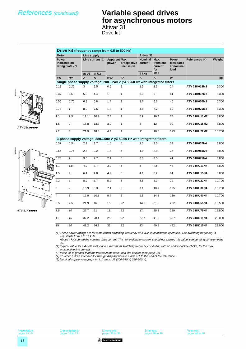
Drive kit (frequency range from 0.5 to 500 Hz)Motor Line supply Altivar 31Powerindicated on rating plate (1)
Line current (2) Apparent power
Max. prospective line Isc (3)
Nominal current
Max. transient currentfor60 s
Power dissipated at nominal load
References (4) Weight
at U1 at U2 4 kHzkW HP A A KVA kA A A W kg
Single phase supply voltage: 200…240 V (5) 50/60 Hz with integrated filters0.18 0.25 3 2.5 0.6 1 1.5 2.3 24 ATV 31K018M2 6.300
0.37 0.5 5.3 4.4 1 1 3.3 5 41 ATV 31K037M2 6.300
0.55 0.75 6.8 5.8 1.4 1 3.7 5.6 46 ATV 31K055M2 6.300
0.75 1 8.9 7.5 1.8 1 4.8 7.2 60 ATV 31K075M2 6.300
1.1 1.5 12.1 10.2 2.4 1 6.9 10.4 74 ATV 31KU11M2 8.800
1.5 2 15.8 13.3 3.2 1 8 12 90 ATV 31KU15M2 8.800
2.2 3 21.9 18.4 4.4 1 11 16.5 123 ATV 31KU22M2 10.700
3-phase supply voltage: 380…500 V (5) 50/60 Hz with integrated filters0.37 0.5 2.2 1.7 1.5 5 1.5 2.3 32 ATV 31K037N4 8.800
0.55 0.75 2.8 2.2 1.8 5 1.9 2.9 37 ATV 31K055N4 8.800
0.75 1 3.6 2.7 2.4 5 2.3 3.5 41 ATV 31K075N4 8.800
1.1 1.5 4.9 3.7 3.2 5 3 4.5 48 ATV 31KU11N4 8.800
1.5 2 6.4 4.8 4.2 5 4.1 6.2 61 ATV 31KU15N4 8.800
2.2 3 8.9 6.7 5.9 5 5.5 8.3 79 ATV 31KU22N4 10.700
3 – 10.9 8.3 7.1 5 7.1 10.7 125 ATV 31KU30N4 10.700
4 5 13.9 10.6 9.2 5 9.5 14.3 150 ATV 31KU40N4 10.700
5.5 7.5 21.9 16.5 15 22 14.3 21.5 232 ATV 31KU55N4 16.500
7.5 10 27.7 21 18 22 17 25.5 269 ATV 31KU75N4 16.500
11 15 37.2 28.4 25 22 27.7 41.6 397 ATV 31KD11N4 23.000
15 20 48.2 36.8 32 22 33 49.5 492 ATV 31KD15N4 23.000
(1) These power ratings are for a maximum switching frequency of 4 kHz, in continuous operation. The switching frequency is adjustable from 2 to 16 kHz.Above 4 kHz derate the nominal drive current. The nominal motor current should not exceed this value: see derating curve on page38.
(2) Typical value for a 4-pole motor and a maximum switching frequency of 4 kHz, with no additional line choke, for the max. prospective line current.
(3) If line Isc is greater than the values in the table, add line chokes (see page 21).(4) To order a drive intended for wire guiding applications, add a T to the end of the reference.(5) Nominal supply voltages, min. U1, max. U2 (200-240 V; 380-500 V).
Presentation:pages 2 to 9
Characteristics:pages 10 to 13
Dimensions:pages 30 to 35
Schemes:pages 36 to 39
Functions:pages 44 to 59
ATV 31K�����
DF
5312
54
ATV 31K�����
DF
5312
55

17
References Variable speed drivesfor asynchronous motors 2
Altivar 31Accessories
Plate for mounting on � railDescription For drives Reference Weight
kgPlate for mountingon � rail,width 35 mm
ATV 31H018M2,ATV 31H037M2,ATV31H055M2, ATV 31H075M2,ATV 31H018M3X, ATV 31H037M3X,ATV H055M3X, ATV 31H075M3X
VW3 A11851 0.200
ATV 31HU11M2, ATV 31HU15M2,ATV 31HU11M3X, ATV 31HU15M3X, ATV 31HU22M3X, ATV 31H037N4, ATV 31H055N4, ATV 31H075N4, ATV 31HU11N4, ATV 31HU15N4, ATV 31H075S6X, ATV 31HU15S6X
VW3 A31852 0.220
UL Type 1 conformity kit (1)Description For drives Reference Weight
kgMechanical devicefixing to the underside of the Altivar 31
ATV 31H018M2,ATV 31H037M2,ATV 31H055M2, ATV 31H075M2
VW3 A31812 0.400
ATV 31H018M3X, ATV 31H037M3X,ATV H055M3X, ATV 31H075M3X
VW3 A31811 0.400
ATV 31HU11M3X, ATV 31HU15M3X VW3 A31813 0.400ATV 31HU11M2, ATV 31HU15M2, ATV 31HU22M3X, ATV 31H037N4, ATV 31H055N4, ATV 31H075N4, ATV 31HU11N4, ATV 31HU15N4, ATV 31H075S6X, ATV 31HU15S6X
VW3 A31814 0.500
ATV 31HU22M2, ATV 31HU30M3X, ATV 31HU40M3X, ATV 31HU22N4, ATV 31HU30N4, ATV 31HU40N4, ATV 31HU22S6X, ATV 31HU40S6X
VW3 A31815 0.500
ATV 31HU55M3X, ATV 31HU75M3X, ATV 31HU55N4, ATV 31HU75N4, ATV 31HU55S6X, ATV 31HU75S6X
VW3 A31816 0.900
ATV 31HD11M3X, ATV 31HD15M3X, ATV 31HD11N4, ATV 31HD15N4, ATV 31HD11S6X, ATV 31HD15S6X
VW3 A31817 1.200
(1) This device allows cables to be connected directly to the drive using conduits or cable glands.
Altivar 28 substitution kitDescription For drives Reference Weight
kgMechanical adaptersallowing an ATV 31 to be used in place of an ATV 28 of the same rating (using the same fixing holes)
ATV 31H018M2,ATV 31H037M2,ATV 31H055M2, ATV 31H075M2ATV 31H018M3X, ATV 31H037M3X,ATV H055M3X, ATV 31H075M3X
VW3 A31821 –
ATV 31HU11M2, ATV 31HU15M2,ATV 31HU11M3X, ATV 31HU15M3X,ATV 31HU22M3X,ATV 31H075S6X, ATV 31HU15S6X
VW3 A31822 –
ATV 31HU55N4, ATV 31HU75N4,ATV 31HU55M3X, ATV 31HU75M3X, ATV 31HU55S6X, ATV 31HU75S6X
VW3 A31823 –
Remote terminalDescription Reference Weight
kgFor ATV 31 drives of all ratings, assembly comprising:- terminal, cable fitted with 2 connectors- seal and screws for IP 65 mounting on an enclosure door
VW3 A31101 –
ESC
ENT
RUNFWO
REV
stopreset
Presentation:pages 2 to 9
Characteristics:pages 10 to 13
Dimensions:pages 30 to 35
Schemes:pages 36 to 39
Functions:pages 44 to 59
DocumentationDescription Reference Weight
kg- Simplified ATV 31 user’s manualand CD-ROM, comprising:- a User’s manual for the drives- a User’s manual for Modbus and CANopen
Supplied with thedrive
– –
International Technical Manual (ITM) CD-ROM DCI CD39811 0.150
VW3 A31101

18
Presentation,characteristics
Variable speed drivesfor asynchronous motors 2
Altivar 31Options: braking resistors
The resistor enables the Altivar 31 drive to operate while braking to a standstill or in braked operation, by dissipating the braking energy. Two types of resistor are available:
- enclosed model (IP 30 enclosure) designed to comply with EMC regulations and protected by a temperature-controlled switch or thermal relay
- non-protected model (IP00) for low power ratings only They are designed for machine applications with high inertia, driving loads, machines with fast cycles.
Presentation
CharacteristicsReferences VW3 A58702 to
VW3 A58704VW3 A58732 to VW3 A58735
VW3 A58736 and VW3 A58737
VW3 A66704
Ambient air temperature °C 40Degree of protection of enclosure
IP 00 IP 30 IP 23
Resistor protection None By temperature-controlled switch (1) By thermal relay (2)Temperature-controlled switch
Trip temperature °C – 130 ± 5% 260 ± 14% –Max. voltage - max. current – � 110 V - 0.3 A � 220 V - 6 A –Min. voltage - min. current – � 24 V - 0.01 A –Maximum contact resistance mΩ – 150 50 –
Load factor of resistors The value of the average power that can be dissipated by the resistor in the enclosure at 40°C is determined for a braking load factor corresponding to the majority of common applications:- braking for 2 seconds with a torque of 0.6 Tn every 40 seconds- braking for 0.8 second with a torque of 1.5 Tn every 40 seconds
Load factor of drives The internal circuits for drives used for braking on external resistors are sized for the following cycles. If they are exceeded, the drive will lock and display a fault. - 1.5 TN for 60 seconds per 140-second cycle- TN continuously
(1) The contact must be connected in sequence (used for signalling or for controlling the line contactor).(2) To be ordered separately, 8 A rating.
Load factor and determining the nominal powerThe value of the average power that can be dissipated by the resistor in the enclosure at 40°C is determined for a braking load factor corresponding to the majority of common applications. This load factor is defined above. For a specific application (e.g. handling), the nominal resistor power has to be redefined by taking account of the new load factor.
Chart 1Graph of the average power as a function of the braking torque for a load factor.
Example:Motor of power Pm = 4 kWMotor efficiency η = 0.85Braking torque Tb = 0.6 TnBraking time t = 10 sCycle time T = 50 sLoad factor Lf = = 20%
Use chart 1 to determine the coefficient K1 corresponding to a braking torque of 0.6 Tn and a load factor of 20%. K1 = 0.06
Chart 2Permissible resistor overload as a function of time (characteristic curve).
Use chart 2 to determine the coefficient K2 corresponding to a braking time of 10 seconds.K2 = 7
The nominal resistor power (Pn) must be greater than:
0
Tt
Speed
Time
Load factor:
t: braking time in sT: cycle time in s
tT---
0,1
0,01
0,0010,1
0,06
1
0,60,5 1 1,5
K1
2%
20%
40%60%
10%
5%
Tb/Tn
tT---
0101 100 1000
2
4
6
8
10
12
14
16
18
20
t (s)
7
K2
Pn Pm K1 η× 1 1K2 Lf×-------------------+⎝ ⎠
⎛ ⎞ 4.103 0.06 0.85 1 17 0.2×-----------------+⎝ ⎠
⎛ ⎞××=× 350W==

19
References Variable speed drivesfor asynchronous motors 2
Altivar 31Options: braking resistors
For drives Min.resistor value
Ohmicvalue
Average power available at
Reference Weight
(1) 40°C(2) 50°CΩ Ω W W kg
Non-protected braking resistorsATV 31H/C/K018M2, ATV 31H/C/K037M2,ATV 31H/C/K055M2, ATV 31H/C/K075M2ATV 31H/C/KU11M2, ATV 31H/C/KU15M2,ATV 31H018M3X, ATV 31H037M3X,ATV 31H055M3X, ATV 31H075M3X,ATV 31HU11M3X, ATV 31HU15M3X, ATV 31H/C/K037N4, ATV 31H/C/K055N4,ATV 31H/C/K075N4,ATV 31H/C/KU11N4, ATV 31H/C/KU15N4,ATV 31H/C/KU22N4ATV 31H075S6XATV 31HU15S6X, ATV31HU22S6X
404027404027808054549664
100 32 28 VW3 A58702 0.600
ATV 31H/C/KU30N4,ATV 31H/C/KU40N4ATV 31HU40S6X
553644
100 40 35 VW3 A58703 0.850
ATV 31H/C/KU22M2, ATV 31HU22M3X, ATV 31HU30M3X
252516
68 32 28 VW3 A58704 0.600
Protected braking resistorsATV 31H/C/K018M2, ATV 31H/C/K037M2,ATV 31H/C/K055M2, ATV 31H/C/K075M2, ATV 31H/C/KU11M2, ATV 31H/C/KU15M2,ATV 31H018M3X, ATV 31H037M3X,ATV 31H055M3X, ATV 31H075M3X,ATV 31HU11M3X, ATV 31HU15M3X, ATV 31H/C/K037N4, ATV 31H/C/K055N4,ATV 31H/C/K075N4,AATV 31H/C/KU11N4, ATV 31H/C/KU15N4,ATV 31H/C/KU22N4
40402740402780805454
100 32 28 VW3 A58732 2.000
ATV 31H/C/KU22M2, ATV 31HU22M3X, ATV 31HU30M3XATV 31H/C/KU30N4,ATV 31H/C/KU40N4ATV 31HU22M3X, ATV 31HU30M3X
25251655362516
68 32 28 VW3 A58733 2.000
ATV 31H/C/KU30N4, ATV 31H/C/KU40N4
5536
100 40 35 VW3 A58734 2.000
ATV 31H/KU55N4,ATV 31H/KU75N4ATV 31HU55S6XATV 31HU75S6X
29193423
60 80 69 VW3 A58735 3.400
ATV 31HU40M3XATV 31H/KD11N4, ATV 31H/KD15N4ATV 31HD11S6X, ATV 31HD15S6X
162024
28 200 173 VW3 A58736 5.100
ATV 31HU55M3X, ATV 31HU75M3X 8 14 400 346 VW3 A58737 6.100
ATV 31HD11M3X, ATV 31HD15M3X 5 10 1000 866 VW3 A66704 (3) 17.000
(1) Depends on the drive rating.(2) Power that can be dissipated by the resistor at the maximum temperature of 115°C, corresponding to a maximum temperature
rise of 75°C in a 40°C environment.(3) The various ohmic values are obtained as a function of the connection, described in the resistor instructions.
VW3 A5873�
5312
32
VW3 A58702
5312
31

20
Presentation,characteristics
Variable speed drivesfor asynchronous motors 2
Altivar 31Options: line chokes
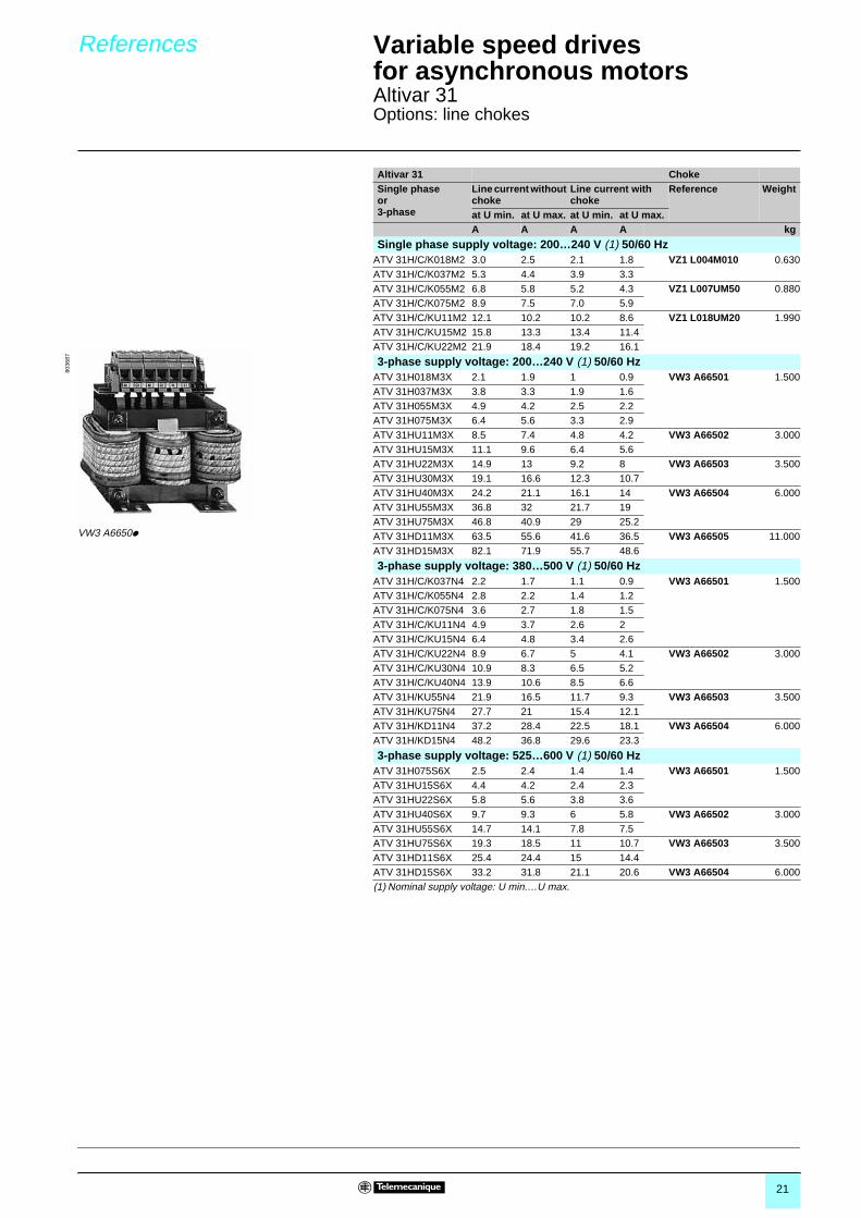
These chokes provide improved protection against overvoltages on the line supply and reduce harmonic distortion of the current produced by the drive.
The recommended chokes are used to limit the line current.They have been developed to conform to standard EN 50178 (VDE 0160 level 1 high energy overvoltages on the line supply).
The values of the chokes are defined for a voltage drop between 3% and 5% of the nominal line voltage. Values higher than this will cause loss of torque.
The use of line chokes is recommended in particular under the following circumstances:� Line supply with significant disturbance from other equipment (interference, overvoltages)� Line supply with voltage imbalance between phases > 1.8% of nominal voltage� Drive supplied with power by a line with very low impedance (in the vicinity of power transformers 10 times more powerful than the drive rating)
The prospective short-circuit current at the point of connection of the drive must not exceed the maximum value indicated in the tables of references. The use of line chokes allows connection on the following networks:
- Max. Isc 22 kA for 200/240 V- Max. Isc 65 kA for 380/500 V and 525/600 V
� Installation of a large number of frequency converters on the same line� Reduction of overload in cos ϕ correction capacitors, if the installation has a power factor correction unit
Presentation
Type of line choke VZ1 L004M010
VZ1 L007UM50
VZ1 L018UM20
VW3 A66501
VW3 A66502
VW3 A66503
VW3 A66504
VW3 A66505
VW3 A66506
CharacteristicsConformity to standards EN 50178 (VDE 0160 level 1 high energy overvoltages on the line supply)
Voltage drop Between 3 and 5% of the nominal line voltage. Values higher than this will cause loss of torque.
Degree of protection Choke IP 00Terminals IP 20 IP 10 IP 00
Value of choke mH 10 5 2 10 4 2 1 0.5 0.3
Nominal current A 4 7 18 4 10 16 30 60 100
Loss W 17 20 30 45 65 75 90 80 –
21
References Variable speed drivesfor asynchronous motors 2
Altivar 31Options: line chokes
Altivar 31 ChokeSingle phaseor3-phase
Line current without choke
Line current with choke
Reference Weight
at U min. at U max. at U min. at U max.A A A A kg
Single phase supply voltage: 200…240 V (1) 50/60 HzATV 31H/C/K018M2 3.0 2.5 2.1 1.8 VZ1 L004M010 0.630ATV 31H/C/K037M2 5.3 4.4 3.9 3.3ATV 31H/C/K055M2 6.8 5.8 5.2 4.3 VZ1 L007UM50 0.880ATV 31H/C/K075M2 8.9 7.5 7.0 5.9ATV 31H/C/KU11M2 12.1 10.2 10.2 8.6 VZ1 L018UM20 1.990ATV 31H/C/KU15M2 15.8 13.3 13.4 11.4ATV 31H/C/KU22M2 21.9 18.4 19.2 16.1
3-phase supply voltage: 200…240 V (1) 50/60 HzATV 31H018M3X 2.1 1.9 1 0.9 VW3 A66501 1.500ATV 31H037M3X 3.8 3.3 1.9 1.6ATV 31H055M3X 4.9 4.2 2.5 2.2ATV 31H075M3X 6.4 5.6 3.3 2.9ATV 31HU11M3X 8.5 7.4 4.8 4.2 VW3 A66502 3.000ATV 31HU15M3X 11.1 9.6 6.4 5.6ATV 31HU22M3X 14.9 13 9.2 8 VW3 A66503 3.500ATV 31HU30M3X 19.1 16.6 12.3 10.7ATV 31HU40M3X 24.2 21.1 16.1 14 VW3 A66504 6.000ATV 31HU55M3X 36.8 32 21.7 19ATV 31HU75M3X 46.8 40.9 29 25.2ATV 31HD11M3X 63.5 55.6 41.6 36.5 VW3 A66505 11.000ATV 31HD15M3X 82.1 71.9 55.7 48.6
3-phase supply voltage: 380…500 V (1) 50/60 HzATV 31H/C/K037N4 2.2 1.7 1.1 0.9 VW3 A66501 1.500ATV 31H/C/K055N4 2.8 2.2 1.4 1.2ATV 31H/C/K075N4 3.6 2.7 1.8 1.5ATV 31H/C/KU11N4 4.9 3.7 2.6 2ATV 31H/C/KU15N4 6.4 4.8 3.4 2.6ATV 31H/C/KU22N4 8.9 6.7 5 4.1 VW3 A66502 3.000ATV 31H/C/KU30N4 10.9 8.3 6.5 5.2ATV 31H/C/KU40N4 13.9 10.6 8.5 6.6ATV 31H/KU55N4 21.9 16.5 11.7 9.3 VW3 A66503 3.500ATV 31H/KU75N4 27.7 21 15.4 12.1ATV 31H/KD11N4 37.2 28.4 22.5 18.1 VW3 A66504 6.000ATV 31H/KD15N4 48.2 36.8 29.6 23.3
3-phase supply voltage: 525…600 V (1) 50/60 HzATV 31H075S6X 2.5 2.4 1.4 1.4 VW3 A66501 1.500ATV 31HU15S6X 4.4 4.2 2.4 2.3ATV 31HU22S6X 5.8 5.6 3.8 3.6ATV 31HU40S6X 9.7 9.3 6 5.8 VW3 A66502 3.000ATV 31HU55S6X 14.7 14.1 7.8 7.5ATV 31HU75S6X 19.3 18.5 11 10.7 VW3 A66503 3.500ATV 31HD11S6X 25.4 24.4 15 14.4ATV 31HD15S6X 33.2 31.8 21.1 20.6 VW3 A66504 6.000(1) Nominal supply voltage: U min.…U max.
VW3 A6650�
8036
87

22
Presentation,characteristics
Variable speed drivesfor asynchronous motors 2
Altivar 31Options: additional EMC input filters
The Altivar 31 has built-in radio interference input filters to meet EMC "product" standards for variable speed drives IEC/EN 61800-3 and to comply with the European EMC (electromagnetic compatibility) directive.
The additional filters enable the drives to meet more stringent requirements: these filters are designed to reduce conducted emissions on the line supply below the limits of standards EN 55011 class A (1) or EN 55022 class B.
These additional filters are installed underneath ATV 31H drives. They can be installed at the side of the product in the case of ATV 31C and K drives. They act as supports for the drives and are fixed to them via tapped holes.
Use of these additional filters is only possible on TN (neutral connection) and TT (neutral to earth) type networks.
The standard IEC 61800-3, annex D2.1, indicates that on IT (impedance earthed or isolated neutral) networks the filters can randomise the operation of insulation monitors.
The efficiency of additional filters on this type of network also depends on the nature of the impedance between neutral and earth and is therefore unpredictable.
If a machine is to be installed on an IT network, one solution is to insert an isolation transformer and to connect locally to the machine on a TN or TT network.
Presentation Function
Use according to the type of network
CharacteristicsConformity to standards EN 133200
Degree of protection IP 21 and IP 41 on upper part
Maximum relative humidity 93% without condensation or dripping water conforming to IEC 68-2-3
Ambient air temperaturearound the device
Operation °C - 10…+ 60Storage °C - 25…+ 70
Maximum operating altitude Without derating m 1000 (above this, derate the current by 1% per additional 100 m)
Vibration resistance Conforming to IEC 60068-2-6 1.5 mm peak to peak from 3 to 13 Hz1 gn peak from 13 to 150 Hz
Shock resistance Conforming to IEC 60068-2-27 15 gn for 11 ms
Max. nominal voltage 50/60 Hz single phase V 240 + 10%
50/60 Hz 3-phase V 240 + 10%500 + 10%600 + 10%

23
References Variable speed drivesfor asynchronous motors 2
Altivar 31Options: additional EMC input filters
For drives FilterReference Maximum length of
shielded cableIn(2)
Il(3)
Loss(4)
Reference Weight
EN 55011 EN 55022class A(1)
class B(2)
m m A mA W kg
Single phase supply voltage: 200…240 V 50/60 HzATV 31H/C/K018M2 50 20 9 100 – VW3 A31401 –ATV 31H/C/K037M2ATV 31H/C/K055M2ATV 31H/C/K075M2ATV 31H/C/KU11M2 50 20 16 150 – VW3 A31403 –ATV 31H/C/KU15M2ATV 31H/C/KU22M2 50 20 22 80 VW3 A31405 –
3-phase supply voltage: 200…240 V 50/60 HzATV 31H018M3X 5 – 7 7 – VW3 A31402 –ATV 31H037M3XATV 31H055M3XATV 31H075M3XATV 31HU11M3X 5 – 15 15 – VW3 A31404 –ATV 31HU15M3XATV 31HU22M3XATV 31HU30M3X 5 – 25 35 – VW3 A31406 –ATV 31HU40M3XATV 31HU55M3X 5 – 47 45 – VW3 A31407 –ATV 31HU75M3XATV 31HD11M3X 5 – 83 15 – VW3 A31408 –ATV 31HD15M3X
3-phase supply voltage: 380…500 V 50/60 HzATV 31H/C/K037N4 50 20 15 15 – VW3 A31404 –ATV 31H/C/K055N4ATV 31H/C/K075N4ATV 31H/C/KU11N4ATV 31H/C/KU15N4ATV 31H/C/KU22N4 50 20 25 35 – VW3 A31406 –ATV 31H/C/KU30N4ATV 31H/C/KU40N4ATV 31H/KU55N4 50 20 47 45 – VW3 A31407 –ATV 31H/KU75N4ATV 31H/KD11N4 50 20 49 45 – VW3 A31409 –ATV 31H/KD15N4(1) The filter selection tables show the length limits for the shielded cables connecting the motors
to the drives for a switching frequency of 2 to 16 kHz. These limits are given as examples only as they vary depending on the interference capacity of the motors and the cables used. If motors are connected in parallel, it is the total length that should be taken into account.
(2) In: Nominal filter current.(3) Maximum earth leakage current at 50 Hz.(4) By heat dissipation.

24
Presentation,characteristics
Variable speed drivesfor asynchronous motors 2
Altivar 31Options: output filters and motor chokes
By inserting an output filter between the drive and the motor, it is possible to:� Limit the dv/dt at the motor terminals (500 to 1500 V/µs), for cables longer than 50 m� Filter interference caused by opening a contactor placed between the filter and the motor� Reduce the motor earth leakage currentWhen using a downstream contactor between the drive and the motor, ferrite suppressors should be fitted to each motor cable for certain drive ratings supplied with a single phase or 3-phase 200 V supply.
(1) Filter performance is ensured if the cable lengths between the motor and the drive given in the above table are not exceeded. For an application with several motors connected in parallel, the cable length must include all tap-offs. If a cable longer than that recommended is used, the filters may overheat.
(2) Please call our Customer Information Centre on 0870 608 8 608 for frequencies greater than 4 kHz or cables longer than 100 m.
Presentation
PrincipleLR filter cell LC filter cell
This cell comprises 3 high frequency chokes and 3 resistors.
This cell comprises 3 high frequency chokesand 3 capacitors.
U1
W1
V1Altivar 31 M1
3
LR filterU1
W1
V1Altivar 31
C C C
LC filter
Motor choke Ferrite suppressors for downstream contactor opening
For standard motor cables longer than 100 m (50 m for shielded cables), a choke can be used to limit overvoltages at the motor terminals.
M1 3
Altivar 31M1
3 Altivar 31 Contactor
Characteristics (1)
LR filter cells(2)
LC filter cells Motor chokes
VW3 A5845� VW3 A6641� VW3 A6650�Drive switching frequency kHz 0.5 ... 4
max.2 or 4 12 4
Length of motor cable Shielded cables m � 100 � 100 � 50 � 100
Unshielded cables m – � 200 � 100 –
Degree of protection IP 20 IP 00 IP 00 IP 20

25
References Variable speed drivesfor asynchronous motors 2
Altivar 31Options: output filters and motor chokes
LR filter cellsFor drives Loss Nominal
currentReference Weight
W A kgATV 31H/C/K018M2ATV 31H/C/K037M2ATV 31H/C/K055M2ATV 31H/C/K075M2ATV 31H/C/KU11M2ATV 31H/C/KU15M2ATV 31H018M3XATV 31H037M3XATV 31H055M3XATV 31H075M3XATV 31HU11M3XATV 31HU15M3XATV 31H/C/K037N4ATV 31H/C/K055N4ATV 31H/C/K075N4ATV 31H/C/KU11N4ATV 31H/C/KU15N4ATV 31H/C/KU22N4ATV 31H/C/KU30N4ATV 31H/C/KU40N4ATV 31H075S6XATV 31HU15S6XATV 31HU22S6XATV 31HU40S6XATV 31HU55S6X
150 10 VW3 A58451 7.400
ATV 31H/C/KU22M2ATV 31HU22M3XATV 31HU30M3XATV 31H/KU55N4ATV 31HU75S6X
180 16 VW3 A58452 7.400
ATV 31HU40M3XATV 31HU55M3XATV 31HU75M3XATV 31H/KU75N4ATV 31HD11S6XATV 31HD15S6X
220 33 VW3 A58453 12.500
LC filter cellsFor drives Reference Weight
kgATV 31HD11M3XATV 31HD15M3X
VW3 A66412 3.500
Motor chokesFor drives Loss Nominal
currentReference Weight
W A kgATV 31H/C/KU22N4ATV 31H/C/KU30N4ATV 31H/C/KU40N4ATV 31HU40S6X, ATV 31HU55S6X
65 10 VW3 A66502 3.000
ATV 31H/C/KU22M2, ATV 31HU22M3XATV 31HU30M3X, ATV 31H/KU55N4ATV 31HU75S6X
75 16 VW3 A66503 3.500
ATV 31HU40M3XATV 31HU55M3XATV 31HU75M3XATV 31H/KU75N4ATV 31H/KD11N4ATV 31HD11S6XATV 31HD15S6X
90 30 VW3 A66504 6.000
ATV 31H/KD15N4 80 60 VW3 A66505 11.000ATV 31HD11M3XATV 31HD15M3X
– 100 VW3 A66506 16.000
Ferrite suppressors for downstream contactor openingFor drives Sold in lots
ofUnitreference
Weightkg
ATV 31H018M2 3 VW3 A31451 –ATV 31H037M2, ATV 31H018M3ATV 31H037M3
3 VW3 A31452 –
ATV 31H055M2, ATV 31H075M2ATV 31HU11M2, ATV 31HU15M2ATV 31H055M3, ATV 31H075M3
3 VW3 A31453 –
5214
25
VW3 A58451

26
Presentation Variable speed drivesfor asynchronous motors 2
Altivar 31Communication options
Modbus and CANopen communication busesThe Altivar 31 can be connected directly to Modbus and CANopen buses by means of an RJ45 connector, which supports both protocols. The communication function provides access to the drive’s configuration, adjustment, control and monitoring functions.
CANopen ModbusConnections via splitter blocks and RJ45 connectors
Connections via junction boxes
1 PLC (1)2 CANopen trunk cable3 CANopen tap junction VW3 CAN TAP24 CANopen drop cable VW3 CAN CA RR��
1 PLC (1)2 Modbus cable depending on the type of
controller or PLC 3 Modbus splitter block LU9 GC34 Modbus drop cables VW3 A8 306 R��
5 Line terminators VW3 A8 306 RC6 Modbus T-junction boxes
VW3 A8 306 TF�� (with cable)
1 PLC (1)2 Modbus cable depending on the type of
controller or PLC 3 Modbus cables TSX CSA�004 T-junction box TSX SCA 505 Subscriber socket TSX SCA 626 Modbus drop cables VW3 A8 3067 Modbus drop cables VW3 A8 306 D30
Connections via screw terminalsIn this case, use a Modbus drop cable VW3 A8 306 D30 and line terminators VW3 A8 306 DRC.
Other communication busesThe Altivar 31 can also be connected to the following networks via a module (bridge or gateway): � Ethernet� Fipio� Profibus DP� DeviceNetThe communication function provides access to the drive’s configuration, adjustment, control and monitoring functions.
1 To network2 Communication modules3 Cables VW3 A8 306 R��,
VW3 P07 306 R10 or VW3 A8 306 D30, depending on the type of module.
4 Modbus splitter block LU9 GC35 Modbus drop cables VW3 A8 306 R��
6 Line terminator VW3 A8 306 RC
(1) Please consult our specialist catalogues.
1
ATV 31
44
3 3 3
4
2
544
1
2 43 46
ATV 31
6 532
6
1
7
45
ATV 31
21
6
ATV 31
ATV 31
55 5
3
4
21
3

27
References Variable speed drivesfor asynchronous motors 2
Altivar 31Communication options
Modbus and CANopen communication busesConnection accessoriesDescription Reference Weight
kgCANopen bus junction box VW3 CAN TAP2 –
Modbus junction box3 screw terminals, RC line terminatorTo be connected using cable VW3 A8 306 D30
TSX SCA 50 0.520
Modbus subscriber socket2 female 15-way SUB-D connectorsand 2 screw terminals, RC line terminatorTo be connected using cable VW3 A8 306
TSX SCA 62 0.570
Modbus splitter block10 RJ45 connectors and 1 screw terminal
LU9 GC3 0.500
Modbus lineterminators(1)
For RJ45 connector
R = 120 Ω, C = 1 nF VW3 A8 306 RC 0.200
R = 150 Ω VW3 A8 306 R 0.200
For screw terminals
R = 120 Ω, C = 1 nF VW3 A8 306 DRC 0.200
R = 150 Ω VW3 A8 306 DR 0.200
Modbus T-junction boxes With integrated cable (0.3 m) VW3 A8 306 TF03 –
With integrated cable (1 m) VW3 A8 306 TF10 –
Connecting cablesDescription Length
mConnectors Reference Weight
kgCablesfor CANopen bus
0.3 m 2 RJ45 connectors VW3 CAN CA RR03 0.05010 m 2 RJ45 connectors VW3 CAN CA RR1 0.500
Cables forModbus bus
3 1 RJ45 connectorand one end stripped
VW3 A8 306 D30 0.150
3 1 RJ45 connector and 1 male 15-way SUB-D connector for TSX SCA 62
VW3 A8 306 0.150
0.3 2 RJ45 connectors VW3 A8 306 R03 0.050
1 2 RJ45 connectors VW3 A8 306 R10 0.050
3 2 RJ45 connectors VW3 A8 306 R30 0.150
Cables for Profibus gateway LA9 P307
1 2 RJ45 connectors VW3 P07 306 R10 0.050
RS 485 double shielded twisted pair cables
100 Supplied without connector TSX CSA 100 –
200 Supplied without connector TSX CSA 200 –
500 Supplied without connector TSX CSA 500 –
Other communication buses Description Cables to be connected Reference Weight
kgEthernet/Modbus bridgewith 1 x Ethernet 10baseT port (RJ45)
VW3 A8 306 D30 174 CEV 300 20 (2) 0.500
Fipio/Modbus gateway(2)
VW3 A8 306 R�� LUF P1 0.240
DeviceNet/Modbus gateway(2)
VW3 A8 306 R�� LUF P9 0.240
Profibus DP/Modbus gatewayParameters set using standard Profibus DP configurator (2)
VW3 P07 306 R10 LA9 P307 0.240
Profibus DP/Modbus gatewayParameters set using ABC Configurator software (2)
VW3 A8 306 R�� LUF P7 0.240
(1) Sold in lots of 2.(2) Please consult our specialist catalogue.
TSX SCA 50
5630
28
TSX SCA 62
5630
29
174 CEV 300 20
LUF P1 LA9 P307
5630
3056
3031
5630
32

28
Presentation PowerSuite software workshop
The PowerSuite software workshop, for PC or Pocket PC, is designed for setting up Telemecanique starters and variable speed drives.
This single program is an easy-to-use interface for configuring Altistart and Tesys model U starters as well as all Altivar drives in a Microsoft Windows® environment,in five languages (English, French, German, Italian and Spanish).
The PowerSuite software workshop can be used for preparing, programming, setting up and maintaining Telemecanique starters and variable speed drives.
The PowerSuite software workshop can be used: b stand alone to prepare and store starter or drive configuration files,b connected to the starter or drive to:v configure,v adjust,v monitor (except for Altivar 11 drives),v control (except for Altivar 11 drives),v transfer and compare configuration files between PowerSuite and the starter or drive.
The configuration files generated by the PowerSuite software workshop can be:b saved to hard disk, CD-Rom, floppy disk, etc...b printed,b exported to office automation software applications,b exchanged between a PC and a Pocket PC using standard synchronization software. PowerSuite PC and Pocket PC configuration files have the same format,b they are password protected.
The software associated with the Altivar 31 has been enhanced to include:oscilloscope function, parameter name customisation, creation of a user menu, creation of monitoring screens, searching and sorting on different parameters.The PowerSuite software workshop has on-line contextual help.
b The PowerSuite software workshop can be connected directly to the terminal port on the starter or variable speed drives, via the serial port on the PC or Pocket PC.Two types of connection are possible:
- either with a single starter or drive (point to point connection)- or with a group of starters or drives (multi-point connection).
b The PowerSuite software workshop for PC can be connected to an Ethernet network (please refer to our “Soft Starters and VSD” catalogue). In this case the starters and drives can be accessed using:
- either an Ethernet-Modbus 174 bridge CEV 300 20,- or a communication option card VW3 A58310 (for Altivar 38, 58 and 58F drives
only).
b The PowerSuite for PC software workshop can operate in the following PC environments and configurations:v Microsoft Windows® 95 OSR2, Microsoft Windows® 98 SE, Microsoft Windows® NT4 X SP5, Microsoft Windows® Me, Microsoft Windows® 2000, Microsoft Windows® XP,v Pentium III, 800 MHz, hard disk with 300 Mb available, 128 Mb RAM,v SVGA or higher definition monitor
b The PowerSuite for Pocket PC software workshop, version V2.0.0, is compatible with Pocket PCs equipped with Windows for Pocket PC 2002 or 2003 operating system and an ARM or XSCALE processor.Performance tests for version V2.00 of the PowerSuite software workshop have been carried out on the following Pocket PCs:v Hewlett Packard® IPAQ 2210,v Compaq® IPAQ series 3800 and 3900,v Hewlett Packard® Jornada series 560.
Presentation
Functions
5318
19
PowerSuite with PC screenInstallation management
5318
20
PowerSuite with PC screenMonitoring screen
Connections
Hardware and software environment
5314
40
PowerSuite with Pocket PC screen

29
References,compatibility
PowerSuite software workshop
ReferencesPowerSuite software workshop for PC or Pocket PC (1)Description Composition Reference Weight
kgPowerSuite for PC kit b 1 PowerSuite CD-Rom
b 1 PC connection kit.VW3 A8101 0.400
PowerSuite for Pocket PC kit (2)
b 1 PowerSuite CD-Rom,b 1 Pocket PC connection kit.
VW3 A8102 0.400
PowerSuite CD-Rom b Software for PC and Pocket PC in English, French, German, Italian and Spanish,
b technical documentation and ABC configurator program.
VW3 A8104 0.100
PowerSuite upgrade CD b Software for PC and Pocket PC in English, French, German, Italian and Spanish,
b technical documentation and ABC configurator program.
VW3 A8105 0.100
PC connection kit b 2 x 3 m connection cables with 2 x RJ 45 connectors,b 1 RJ 45/9-way SUB-D adapter for connecting ATV 58/58F/38
drives,b 1 RJ 45/9-way SUB-D adapter for connecting ATV 68 drives,b 1 converter marked “RS 232/RS 485 PC” with one 9-way female
SUB-D connector and one RJ 45 connector,b 1 converter for ATV 11 drives, with one 4-way male connector and
one RJ 45 connector.
VW3 A8106 0.350
Pocket PC connection kit (2)
b 2 x 0.6 m connection cables with 2 x RJ 45 connectors,b 1 RJ 45/9-way SUB-D adapter for connecting ATV 58/58F/38
drives,b 1 converter marked “RS 232/RS 485 PPC” with one 9-way male
SUB-D connector and one RJ 45 connector,b 1 converter for ATV 11 drives, with one 4-way male connector and
one RJ 45 connector.
VW3 A8111 0.300
(1) To find out about the latest available version, please call our Customer Information Centre on 0870 608 8 608.(2) These kits connect to the synchronization cable, which must be ordered separately from your Pocket PC supplier.
CompatibilityCompatibility of the PowerSuite software workshop with starters and variable speed drives
Starter-controller
Soft start/soft stop unit
Variable speed drives
TeSysmodel U
ATS 48 ATV 11 ATV 28 ATV 31 ATV 38 ATV 58ATV 58F
ATV 68
PowerSuite software workshop with serial link for PCKit and CD-Rom VW3 A8101
VW3 A8104VW3 A8105
uuuu V 1.40 uuuu V 1.30 uuuu V 1.40 uuuu V 1.0 uuuu V 2.0.0 uuuu V 1.40 uuuu V 1.0 uuuu V 1.50
PowerSuite software workshop with Ethernet link for PCKit and CD-Rom VW3 A8101
VW3 A8104VW3 A8105
– uuuu V 1.50andEthernet-Modbusbridge
– uuuu V 1.50andEthernet-Modbusbridge
uuuu V 2.0.0andEthernet-Modbusbridge
uuuu V 1.50and Ethernet V2 communication card or bridge
–
PowerSuite software workshop for Pocket PCKit and CD-Rom VW3 A8102
VW3 A8104VW3 A8105
uuuu V 1.50 uuuu V 1.30 uuuu V 1.40 uuuu V 1.20 uuuu V 2.0.0 uuuu V 1.40 uuuu V 1.20 –
Compatible products and software versions. Non compatible products.
Compatibility of the PowerSuite software workshops with Pocket PCsOperating system Performance tests carried out on models PowerSuite software version
V 1.30 V 1.40 V 1.50 V 2.0.0Windows for Pocket PC 2003 Hewlett Packard® IPAQ 2210 no no no yesWindows for Pocket PC 2002 Compaq® IPAQ series 3800, 3900 no no yes yes
Hewlett Packard® Jornada series 560 no yes yes yesWindows for Pocket PC 2000 Hewlett Packard® Jornada series 525 yes yes yes noWindows CE Hewlett Packard® Jornada 420 yes no no no
VW3 A8101
5630
20
VW3 A8102
5630
19

30
Dimensions Variable speed drivesfor asynchronous motors 2
Altivar 31
ATV 31H0��M3X/MXA, ATV 31H0��M2/M2APlate for EMC mounting(supplied with the drive)
ATV 31H c018M3X, 037M3X 120055M3X, 075M3X 130018M2, 037M2 130055M2, 075M2 140
(1) Only for drives whose reference ends in A.
ATV 31HU��M2/M2A, ATV 31HU1�M3X/M3XA to ATV 31HU4�M3X/M3XA, ATV 31H0��N4/N4A to ATV 31HU40N4/N4A, ATV 31H075S6X to ATV 31HU40S6X
Plate for EMC mounting(supplied with the drive)
ATV 31H a b c d G H J K ØU1�M3X 105 143 130 49 93 121.5 5 16.5 2x5U1�M2, U22M3X037N4 to U15N4U75S6X, U15S6X
105 143 150 49 93 121.5 5 16.5 2x5
U22M2, HU�0M3XU22N4 to U40N4U22S6X, U40S6X
140 184 150 48 126 157 6.5 20.5 4x5
(1) Only for drives whose reference ends in A.
ATV 31HU55M3X/M3XA, ATV 31HU75M3X/M3XA, ATV 31HU55N4/N4A, ATV 31HU75N4/N4A, ATV 31HU55S6X, ATV 31HU75S6XPlate for EMC mounting(supplied with the drive)
(1) Only for drives whose reference ends in A.
ATV 31HD1�M3X/M3XA, ATV 31HD1�N4/N4A, ATV 31HD1�S6XPlate for EMC mounting(supplied with the drive)
(1) Only for drives whose reference ends in A.
8 (1)
2xØ5
c
60
121,
5
518
,5145
= =
72
50
4xM4M5
2xM5 screw
c
8 (1)
Ø
JK
Hb
G= =
a
d
4xM4M5
2xM5 screw
=
170
8 (1)
232
210
175
160=
180
4xØ5
75
4xM4 M5
190
225
4xØ6
= =
245
8 (1)
329,
5
295
727
,5
4xM4
75
M5
Presentation:pages 2 to 9
Characteristics:pages 10 to 13
References:pages 14 to 17
Schemes:pages 36 to 39
Functions:pages 44 to 59
2xM5 screw
2xM5 screw

31
Dimensions Variable speed drivesfor asynchronous motors 2
Altivar 31Enclosed drive
ATV 31C0��M2
ATV 31CU11M2, ATV 31CU15M2, ATV 31C0��N4, ATV 31CU11N4, ATV 31CU15N4
ATV 31CU22M2, ATV 31CU22N4, ATV 31CU30N4, ATV 31CU40N4
210
218
240
192
4xØ5,5
163
215
277
197192
297
4xØ5,5
230
340
212208
318
4xØ5,5
Presentation:pages 2 to 9
Characteristics:pages 10 to 13
References:pages 14 to 17
Schemes:pages 36 to 39
Functions:pages 44 to 59

32
Dimensions Variable speed drivesfor asynchronous motors 2
Altivar 31Drive kit
ATV 31K���M2, ATV 31K0��N4, ATV 31KU22N4, ATV 31KU�0N4Mounting
ATV 31K a a1 b b1 c c1 E F G H K0��M2 254 214 280 240 153 123 10 117 234 260 130U1�M2, 0��N4, U1�N4 250 219 337 297 186 127 1 115 230 317 158.5U22M2, U��N4 265 234 380 340 209 134 1 122.5 245 360 180Note: product supplied with drilling template.
ATV 31KU55N4, ATV 31KU75N4, ATV 31KD1�N4/�M2Mounting
ATV 31K a a1 a2 b b1 c E F G H J K K1 ØU55N4, U75N4 400 340 334 600 444 343 12 155 250 49 500 180 0 12 x 6D11N4, D15N4 450 370 386 700 546 267 13 180 280 39 600 150 180 14 x 6Note: product supplied with drilling template.
F
G
H
K
b
c
a
c1
G
7xØ5,5
H
K
b110
a1 E
F
G
8xØ8
3030
J b
3535
1515
ac
a1
F
E
19 19F
HH
7
KK
1K
b1
a2
Ø
Presentation:pages 2 to 9
Characteristics:pages 10 to 13
References:pages 14 to 17
Schemes:pages 36 to 39
Functions:pages 44 to 59

33
Dimensions (continued) Variable speed drivesfor asynchronous motors 2
Altivar 31
Plates for mounting on � railVW3 A11851 VW3 A31852
UL NEMA Type 1 conformity kitVW3 A31811 to VW3 A31817
VW3 ΔbA31812 77A31813 and A31814 107A31815 138A31816 179A31817 244(1) Drive(2) Kit for VW3 A3181�
Remote terminalVW3 A31101
Mounting
37,9 77,5
143,
6
40 105
144
b
(2)
(1)
24
4xØ3,5
55,6
52
79,6
Ø36
Presentation:pages 2 to 9
Characteristics:pages 10 to 13
References:pages 14 to 17
Schemes:pages 36 to 39
Functions:pages 44 to 59
34
Dimensions (continued) Variable speed drivesfor asynchronous motors 2
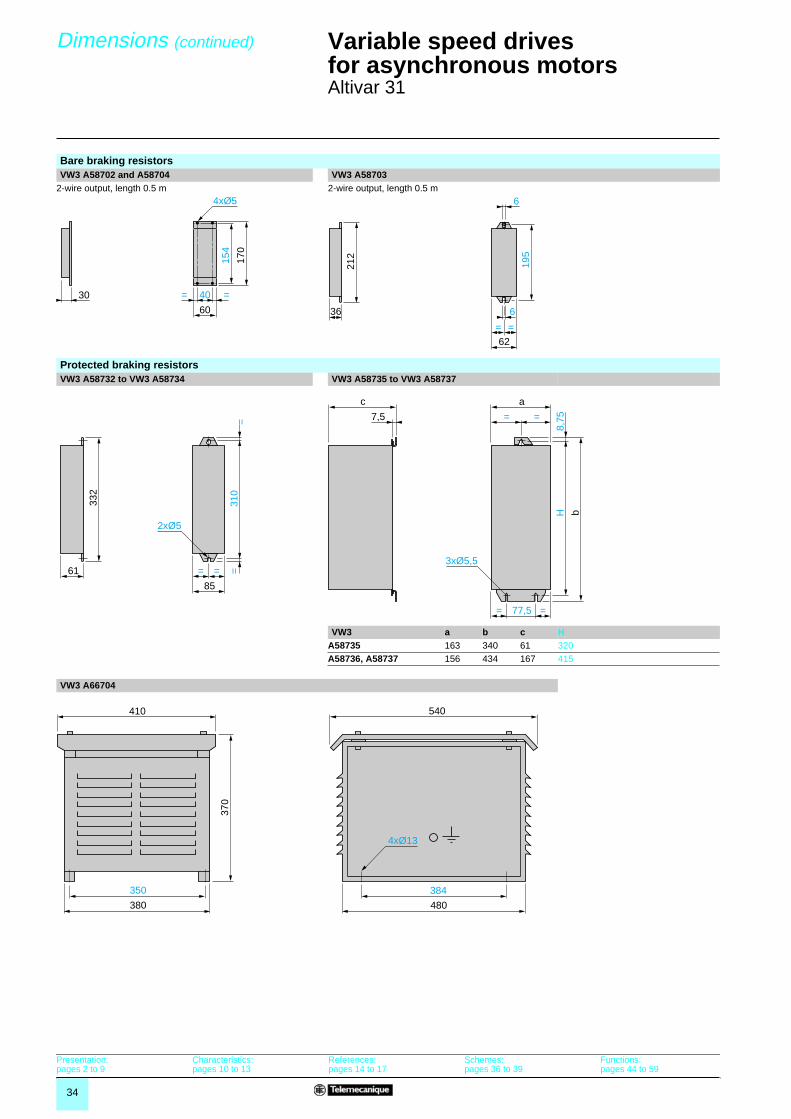
Altivar 31
Bare braking resistorsVW3 A58702 and A58704 VW3 A58703
2-wire output, length 0.5 m 2-wire output, length 0.5 m
Protected braking resistorsVW3 A58732 to VW3 A58734 VW3 A58735 to VW3 A58737
VW3 a b c HA58735 163 340 61 320A58736, A58737 156 434 167 415
VW3 A66704
30 40 ==
154
170
4xØ5
60
62
195
= =
636
212
6
85
310
= = =
=
2xØ5
61
332
c
7,5 = =
= 77,5
a
=
H b
8,75
3xØ5,5
384
480
540
350
380
370
410
4xØ13
Presentation:pages 2 to 9
Characteristics:pages 10 to 13
References:pages 14 to 17
Schemes:pages 36 to 39
Functions:pages 44 to 59

35
Dimensions (continued) Variable speed drivesfor asynchronous motors 2
Altivar 31
Single phase chokes 3-phase chokesVZ1 L������� VW3 A66501 to VW3 A66506
VZ1 a b c G H Ø VW3 a b c c1 G G1 H ØL004M010 60 100 80 50 44 4 x 9 A66501 100 135 55 60 40 60 42 6 x 9L007UM50 60 100 95 50 60 4 x 9 A66502 130 155 85 90 60 80.5 62 6 x 12L018UM20 85 120 105 70 70 5 x 11 A66503 130 155 85 90 60 80.5 62 6 x 12
A66504 155 170 115 135 75 107 90 6 x 12A66505 180 210 125 165 85 122 105 6 x 12A66506 275 210 130 160 105 181 100 11 x 22
Additional EMC input filters:Mounting of filter underneath the drive Mounting of filter adjacent to drive
VW3 a b b1 c G H ØA31401, A31402 72 185 – 50 60 121.5 2 x M4A31403, A31404 105 185 – 60 93 121.5 2 x M4A31405, A31406 140 225 – 60 126 157 4 x M4A31407 180 275 – 60 160 210 4 x M4A31408, A31409 245 365 – 60 295 225 4 x M5
Output filters Ferrite suppressors for downstream contactor openingVW3 A58451 to VW3 A58453 VW3 A31451 to VW3 A31452
VW3 a b c G H Ø VW3 a b c ØA58451A58452
169.5 340 123 150 315 7 A31451 33.5 33 33 13A31452 33 21.5 22.5 9
A58453 239 467.5 139.5 212 444 7 A31453 30 19 19 6
H
Ø
c
G
a
b
H
8xØ
c
c1
G
G1
a
b
c
b b1H=
=
G= =a
Ø
cab
Ø
c G
H
4xØ
a
b
c
b
aØ
Presentation:pages 2 to 9
Characteristics:pages 10 to 13
References:pages 14 to 17
Schemes:pages 36 to 39
Functions:pages 44 to 59

36
Schemes,combinations
Variable speed drivesfor asynchronous motorsAltivar 31
ATV 31ppppppppppppppppM3X, ATV 31ppppppppppppppppN4, ATV 31ppppppppppppppppS6X ATV 31ppppppppppppppppM23-phase power supply Single phase power supply
(1) Line choke (single phase or 3-phase).(2) Fault relay contacts. For remote signalling of drive status.(3) Shared connection of the logic inputs depends on the position of a switch, see diagrams below.Note: All terminals are located at the bottom of the drive.Fit interference suppressors to all inductive circuits near the drive or connected on the same circuit, such as relays, contactors, solenoid valves, fluorescent lighting, etc.Compatible components (for full references, please consult our specialist catalogue.Code Description
Q1 GV2 L or Compact NS (see pages 40 to 43)KM1 LC1 ppp + LA4 DA2U (see pages 40 to 43)S1, S2 XB2 B or XA2 B pushbuttonsT1 100 VA transformer 220 V secondaryQ2 GV2 L rated at twice the nominal primary current of T1Q2 GB2 CB05
Examples of recommended circuit diagramsLogic input switches AOC output
“Source” position “Sink” position CLI position with PLC transistor outputs Wired as logic output
2-wire control 3-wire control Analog voltage inputs Analog current input± 10 V external ± 10 V external 0-20 mA, 4-20 mA, X-Y mA
PA
/+
W P0
PC
/-
U V AI2
CO
M
AI3
AO
V
AO
C
PB + 1
0
AI1
L1 L2 L3
R1A
R1C
R1B LI
1
LI2
LI3
LI4
+ 2
4
CLI
U1
W1
V1
M 3
X-Y mA
0 ± 10 V
(3)
(2)
(1)
LI5
LI6
T1KM1
A2A1
3 4 5 6
Q2
1 2
R1A R1C 13 14
Q1
2 4 6
KM1
Q21 2 Q3 S2 S1
KM1
1 3 5
A1
A1
2 4 6
1 3 5
R2A
R2C
Brakingresistor
ReferencepotentiometerSZ1 RV1202
X-Y mA
0 ± 10 V
R1A
R1C
R1B
(2)
R2A
R2C LI
1
LI2
LI3
LI4
+ 2
4
CLI
(3)
LI5
LI6
PA
/+
W P0
PC
/-
U V AI2
CO
M
AI3
AO
V
AO
C
PB + 1
0
AI1
L1 L2
U1
W1
V1
M 3
(1)
T1KM1
A2A1
3 4 5 6
Q2
1 2
R1A R1C 13 14
Q1
2 4 6
KM1
Q21 2 Q3 S2 S1
KM1
1 3 5
A1
A1
1 3
2 4
Brakingresistor Reference
potentiometerSZ1 RV1202
+ 2
4 V
0 V
LI1
24 V
CO
M
LI1
CLI
CO
M
LI1
0 V
24 V
PLC
CLI
CO
M
LI1
0 V 24 VPLC
AO
C
0 V
24 V relay10 mA
ATV 31 control terminals
LI1
+ 2
4 V
LIx
ATV 31 control terminals
LI1: ForwardLIx: Reverse
LI1
LI2
+ 2
4 V
LIx
ATV 31 control terminals
LI1: StopLI2: ForwardLIx: Reverse
AI1
0 V
+ 10 V
Speedreferencepotentiometer2.2 to 10 kΩ
ATV 31 control terminals
AI2
0 V
± 10 V
ATV 31 control terminals
AI3
0 V
Source0-20 mA4-20 mAX-Y mA
ATV 31 control terminals
Presentation:pages 2 to 9
Characteristics:pages 10 to 13
References:pages 14 to 17
Dimensions:pages 30 to 35
Functions:pages 44 to 59

37
Schemes,connections,mounting
Variable speed drivesfor asynchronous motorsAltivar 31Electromagnetic compatibility
SchemesAdditional radio interference suppression input filters VW3 A3140pppp
3-phase power supply Single phase power supply
Connections to meet the requirements of EMC standardsPrinciple
b Grounds between the drive, motor and cable shielding must have “high frequency” equipotentiality.b Use shielded cables with the shielding connected to ground throughout 360˚ at both ends for the motor cable, the braking resistor cable and the control/command cables. Metal ducting or conduit can be used for part of the shielding length provided that there is no break in continuity.b Ensure maximum separation between the power supply cable (line supply) and the motor cable.
Installation diagram for ATV 31Hpppppppppppp drives
1 Steel plate supplied with the drive, to be fitted on it (machine ground)2 Altivar 31 3 Non-shielded power supply wires or cable4 Non-shielded wires for the output of the safety relay contacts.5 Fix and ground the shielding of cables 6, 7 and 8 as close as possible to the drive:
- Strip the shielding.- Use cable clamps of an appropriate size on the parts from which the shielding has been stripped, to attach them to the plate 1.The shielding must be clamped tightly enough to the metal plate to ensure good contact.Cable clamps must be made from stainless steel.
6 Shielded cable for connecting the motor.7 Shielded cable for connecting the control/command wiring. For applications
requiring several conductors, use cables with a small cross-section (0.5 mm2).8 Shielded cable for connecting the braking resistor.
6, 7, 8, the shielding must be connected to ground at both ends. The shielding must be continuous and intermediate terminals must be in EMC shielded metal cases.
9 Ground screw for the motor cable with low ratings, as the screw on the heatsink is inaccessible.
Note: The HF equipotential ground connection between the drive, motor and cable shielding does not remove the need to connect the PE protective conductors (green-yellow) to the appropriate terminals on each unit.If using an additional input filter, it should be mounted beneath the drive and connected directly to the line supply via an unshielded cable. Link 3 on the drive is then via the filter output cable.
Operation on an IT systemIT system: isolated or impedance earthed neutral.Use a permanent insulation monitor compatible with non-linear loads, e.g. Merlin Gerin type XM200.
ATV 31pppM2 and N4 drives feature built-in RFI filters. There are two ways of isolating these filters from ground for operation on an IT system:b ATV 31H018M2 to ATV 31HU22M2 and ATV 31H037N4 to ATV 31HU40N4, pull out a jumper to disconnect the filter.b ATV 31HU55N4 to ATV 31HD15N4, move the cable tag to disconnect the filter.
L'1
L'2
L'3
L1 L2 L3
L1 L2 L3
VW3 A3140
ATV 31
VW3 A3140
ATV 31
L'1
L'2
L1 L2
L1 L2
1
3
8
9
74
5
6
2
Presentation:pages 2 to 9
Characteristics:pages 10 to 13
References:pages 14 to 17
Dimensions:pages 30 to 35
Functions:pages 44 to 59

38
Mountingand installation recommendations
Variable speed drivesfor asynchronous motorsAltivar 31
Depending on the conditions in which the drive is to be used, its installation will require certain precautions and the use of appropriate accessories.
b Type A mounting
b Type B mounting
b Type C mounting
Removing the protective cover from the top of the drive (as shown opposite) changes the degree of protection to IP 20.
Derating curves for the nominal drive current (In) as a function of the temperature, switching frequency and type of mounting.
For intermediate temperatures (e.g. 55˚C), interpolate between 2 curves.
Mounting recommendations for ATV 31H drivesInstall the unit vertically, at ± 10˚.b Do not place it close to heating elements.b Leave sufficient free space to ensure that the air required for cooling purposes can circulate from the bottom to the top of the unit.
Types of mounting
≥ d ≥ d
≥50
mm
≥50
mm ≥ 10 mm
Removing the protective cover
≥ 50 mm ≥ 50 mm
≥ 50 mm ≥ 50 mm
I / In100 %
- 5 %
- 10 %90 %
80 %
70 %
60 %
50 %
40 %
30 %4 kHz 8 kHz 12 kHz 16 kHz
In
- 15 %
- 25 %
- 35 %
- 10 %
- 20 %
- 30 %
- 40 %
- 50 %
- 25 %
- 35 %
- 45 %
- 55 %
- 65 %
Switching frequency
40˚C Mounting types A and B
50˚C Mounting type C
50˚C Mounting types A and B
60˚C Mounting type C
60˚C Mounting types A and B
Presentation:pages 2 to 9
Characteristics:pages 10 to 13
References:pages 14 to 17
Dimensions:pages 30 to 35
Functions:pages 44 to 59

39
Mountingand installation recommendations (continued)
Variable speed drivesfor asynchronous motors 2
Altivar 31
Specific recommendations for mounting ATV 31 drives in a wall-mounted or floor-standing enclosure
Observe the mounting recommendations on the opposite page.To ensure proper air circulation in the drive:b Fit ventilation grilles.b Ensure that there is sufficient ventilation. If there is not, install forced ventilation with a filter. The openings and/or fans must provide a flow rate at least equal to that of the drive fans (see the table below).b Use special filters with IP 54 protection.b Remove the protective cover from the top of the drive.
Fan flow rate depending on the drive ratingATV 31 drive Flow rate m3/min
H018M2, H037M2, H055M2, H018M3X, H037M3X, H055M3X, H037N4, H055N4, H075N4, HU11N4, H075S6X, HU15N6X
0.3
H075M2, HU11M2, HU15M2, H075M3X, HU11M3X, HU15M3X, HU15N4, HU22N4, HU22S6X, HU40N6X
0.55
HU22M2, HU22M3X, HU30M3X, HU40M3X, HU30N4, HU40N4, HU55S6X, HU75S6X
1.55
HU55M3X, HU55N4, HU75N4, HD11S6X 1.7
HU75M3X, HD11M3X, HD11N4, HD15N4, HD15S6X
2.8
HD15M3X 3.6
Dust and damp proof metal wall-mounted or floor-standing enclosure (IP 54 degree of protection)
The drive must be mounted in a dust and damp proof enclosure in certain environmental conditions: dust, corrosive gases, high humidity with risk of condensation and dripping water, splashing liquid, etc.This enables the drive to be used in an enclosure where the maximum internal temperature can reach 50˚C.
Calculating the size of the enclosureMaximum thermal resistance Rth (˚C/W)
θ = maximum temperature inside enclosure in ˚Cθe = maximum external temperature in ˚CP = total power dissipated in the enclosure in W
Power dissipated by drive: see page 14.Add the power dissipated by the other equipment components.
Useful heat dissipation surface of enclosure S (m2)(sides + top + front panel if wall-mounted)
K = thermal resistance per m2 of enclosure.
For metal enclosures: K = 0.12 with internal fan, K = 0.15 without fan
Note: Do not use insulated enclosures as they have a poor level of conductivity.
Mounting recommendations for ATV 31 drivesInstall the unit vertically, at ± 10˚.Do not place it close to heating elements.Leave sufficient free space to ensure that the air required for cooling purposes can circulate from the bottom to the top of the unit.
Rthθ° θe–
P------------------=
Sk
Rth---------=
≥ 10
0 m
m10
0 m
m
Presentation:pages 2 to 9
Characteristics:pages 10 to 13
References:pages 14 to 17
Dimensions:pages 30 to 35
Functions:pages 44 to 59

40
Combinations forself-assembly
Variable speed drivesfor asynchronous motors 2
Altivar 31Motor starters
The combinations suggested below can be used to assemble a complete motor starter comprising a circuit-breaker, a contactor and an Altivar 31 variable speed drive.The circuit-breaker provides protection against accidental short-circuits, isolation, and padlocking if required.The contactor provides control and management of any safety features and isolation of the motor on stopping.The Altivar 31 variable speed drive is electronically protected against short-circuits between phases and between phase and earth; it therefore provides continuity of service and thermal protection of the motor.
Applications
Motor starter for drive with heatsinkVariable speeddriveReference
Standard power rating of 4-pole 50/60 Hz motors (1)
Circuit-breaker (2) Max.prosp. line Isc
Contactor (3) Add the voltage number to the basic reference to obtain the full reference (4)
Reference Rating
kW HP A kA
Single phase supply voltage: 200…240 VATV 31H018M2 0.18 0.25 GV2 L08 4 1 LC1 K0610ATV 31H037M2 0.37 0.5 GV2 L10 6.3 1 LC1 K0610ATV 31H055M2 0.55 0.75 GV2 L14 10 1 LC1 K0610ATV 31H075M2 0.75 1 GV2 L14 10 1 LC1 K0610ATV 31HU11M2 1.1 1.5 GV2 L16 14 1 LC1 K0610ATV 31HU15M2 1.5 2 GV2 L20 18 1 LC1 K0610ATV 31HU22M2 2.2 3 GV2 L22 25 1 LC1 D09
3-phase supply voltage: 200…240 VATV 31H018M3X 0.18 0.25 GV2 L07 2.5 5 LC1 K0610ATV 31H037M3X 0.37 0.5 GV2 L08 4 5 LC1 K0610ATV 31H055M3X 0.55 0.75 GV2 L10 6.3 5 LC1 K0610ATV 31H075M3X 0.75 1 GV2 L14 10 5 LC1 K0610ATV 31HU11M3X 1.1 1.5 GV2 L14 10 5 LC1 K0610ATV 31HU15M3X 1.5 2 GV2 L16 14 5 LC1 K0610ATV 31HU22M3X 2.2 3 GV2 L20 18 5 LC1 K0610ATV 31HU30M3X 3 – GV2 L22 25 5 LC1 D09ATV 31HU40M3X 4 5 GV2 L22 25 5 LC1 D09ATV 31HU55M3X 5.5 7.5 NS80HMA 50 22 LC1 D32ATV 31HU75M3X 7.5 10 NS80HMA 50 22 LC1 D32ATV 31HD11M3X 11 15 NS80HMA 80 22 LC1 D40ATV 31HD15M3X 15 20 NS100HMA 100 22 LC1 D40
3-phase supply voltage: 380…500 VATV 31H037N4 0.37 0.5 GV2 L07 2.5 5 LC1 K0610ATV 31H055N4 0.55 0.75 GV2 L08 4 5 LC1 K0610ATV 31H075N4 0.75 1 GV2 L08 4 5 LC1 K0610ATV 31HU11N4 1.1 1.5 GV2 L10 6.3 5 LC1 K0610ATV 31HU15N4 1.5 2 GV2 L14 10 5 LC1 K0610ATV 31HU22N4 2.2 3 GV2 L14 10 5 LC1 K0610ATV 31HU30N4 3 – GV2 L16 14 5 LC1 K0610ATV 31HU40N4 4 5 GV2 L16 14 5 LC1 K0610ATV 31HU55N4 5.5 7.5 GV2 L22 25 22 LC1 D09ATV 31HU75N4 7.5 10 GV2 L32 32 22 LC1 D18ATV 31HD11N4 11 15 NS80HMA 50 22 LC1 D32ATV 31HD15N4 15 20 NS80HMA 50 22 LC1 D32(1) The HP values given are NEC-compliant (National Electrical Code). (2) NS80HMA: product sold under the Merlin Gerin brand.(3) Composition of contactors
LC1-K06: 3 poles + 1 "N/O" auxiliary contactLC1-D09/D32/D40: 3 poles + 1 "N/O" auxiliary contact
(4) Usual control circuit voltages.
a.c. control circuitVolts � 24 48 110 220 230 240
LC1-D 50 Hz B5 E5 F5 M5 P5 U560 Hz B6 E6 F6 M6 – U650/60 Hz B7 E7 F7 M7 P7 U7Volts � 24 48 110 220/230 230 230/240
LC1-K 50/60 Hz B7 E7 F7 M7 P7 U7For other voltages between 24 and 660 V, or d.c. control circuit, please call our Customer Information Centre on 0870 608 8 608.
5214
6680
3714
5312
50
GV2 L+LC1 K+ATV 31H������

41
Combinations forself-assembly
Variable speed drivesfor asynchronous motors 2
Altivar 31Motor starters
The combinations suggested below can be used to assemble a complete motor starter comprising a circuit-breaker, a contactor and an Altivar 31 variable speed drive.The circuit-breaker provides protection against accidental short-circuits, isolation, and padlocking if required.The contactor provides control and management of any safety features and isolation of the motor on stopping.The Altivar 31 variable speed drive is electronically protected against short-circuits between phases and between phase and earth; it therefore provides continuity of service and thermal protection of the motor.
Applications
Motor starter for drive with heatsinkVariable speeddriveReference
Standard power rating of 4-pole 50/60 Hz motors (1)
Circuit-breaker (2) Max.prosp. line Isc
Contactor (3) Add the voltage number to the basic reference to obtain the full reference (4)
Reference Rating
kW HP A kA
3-phase supply voltage: 525…600 VATV 31H075S6X 0.75 1 GV2 L08 4 5 LC1 K0610ATV 31HU15S6X 1.5 2 GV2 L10 6.3 5 LC1 K0610ATV 31HU22S6X 2.2 3 GV2 L14 10 5 LC1 K0610ATV 31HU40S6X 4 5 GV2 L16 14 5 LC1 K0610ATV 31HU55S6X 5.5 7.5 GV2 L20 18 22 LC1 K0610ATV 31HU75S6X 7.5 10 GV2 L22 25 22 LC1 K0610ATV 31HD11S6X 11 15 GV2 L32 32 22 LC1 D09ATV 31HD15S6X 15 20 NS80HMA 32 22 LC1 D09(1) The HP values given are NEC-compliant (National Electrical Code). (2) NS80HMA: product sold under the Merlin Gerin brand.(3) Composition of contactors
LC1-K06: 3 poles + 1 "N/O" auxiliary contactLC1-D09/D32/D40: 3 poles + 1 "N/O" auxiliary contact
(4) Usual control circuit voltages.
a.c. control circuitVolts � 24 48 110 220 230 240
LC1-D 50 Hz B5 E5 F5 M5 P5 U560 Hz B6 E6 F6 M6 – U650/60 Hz B7 E7 F7 M7 P7 U7Volts � 24 48 110 220/230 230 230/240
LC1-K 50/60 Hz B7 E7 F7 M7 P7 U7For other voltages between 24 and 660 V, or d.c. control circuit, please call our Customer Information Centre on 0870 608 8 608.
5214
6680
3714
5312
50
GV2 L+LC1 K+ATV 31H������

42
Combinations forself-assembly
Variable speed drivesfor asynchronous motors 2
Altivar 31Motor starters
ApplicationsThe combinations suggested below can be used to assemble a complete motor starter comprising a circuit-breaker, a contactor and an Altivar 31 variable speed drive.The circuit-breaker provides protection against accidental short-circuits, isolation, and padlocking if required.The contactor provides control and management of any safety features and isolation of the motor on stopping.The Altivar 31 variable speed drive is electronically protected against short-circuits between phases and between phase and earth; it therefore provides continuity of service and thermal protection of the motor.
Motor starter for customisable enclosed driveVariable speeddriveReference
Standard power rating of 4-pole 50/60 Hz motors (1)
Circuit-breaker Max.prosp. line Isc
Contactor Add the voltage number to the basic reference to obtain the full reference (2)
Reference Rating
kW HP A kA
Single phase supply voltage: 200…240 VATV 31C018M2 0.18 0.25 GV2 L08 4 1 LC1 K0610ATV 31C037M2 0.37 0.5 GV2 L10 6.3 1 LC1 K0610ATV 31C055M2 0.55 0.75 GV2 L14 10 1 LC1 K0610ATV 31C075M2 0.75 1 GV2 L14 10 1 LC1 K0610ATV 31CU11M2 1.1 1.5 GV2 L16 14 1 LC1 K0610ATV 31CU15M2 1.5 2 GV2 L20 18 1 LC1 K0610ATV 31CU22M2 2.2 3 GV2 L22 25 1 LC1 D09
3-phase supply voltage: 380…500 VATV 31C037N4 0.37 0.5 GV2 L07 2.5 5 LC1 K0610ATV 31C055N4 0.55 0.75 GV2 L08 4 5 LC1 K0610ATV 31C075N4 0.75 1 GV2 L08 4 5 LC1 K0610ATV 31CU11N4 1.1 1.5 GV2 L10 6.3 5 LC1 K0610ATV 31CU15N4 1.5 2 GV2 L14 10 5 LC1 K0610ATV 31CU22N4 2.2 3 GV2 L14 10 5 LC1 K0610ATV 31CU30N4 3 3 GV2 L16 14 5 LC1 K0610ATV 31CU40N4 4 5 GV2 L16 14 5 LC1 K0610(1) The HP values given are NEC-compliant (National Electrical Code). (2) Usual control circuit voltages.
a.c. control circuitVolts � 24 48 110 220 230 240
LC1-D 50 Hz B5 E5 F5 M5 P5 U560 Hz B6 E6 F6 M6 – U650/60 Hz B7 E7 F7 M7 P7 U7Volts � 24 48 110 220/230 230 230/240
LC1-K 50/60 Hz B7 E7 F7 M7 P7 U7For other voltages between 24 and 660 V, or d.c. control circuit, please call our Customer Information Centre on 0870 608 8 608.
5214
6680
3714
5312
52
GV2 L+LC1 K+ATV 31C�����

43
Combinations forself-assembly
Variable speed drivesfor asynchronous motors 2
Altivar 31Motor starters
ApplicationsThe combinations suggested below can be used to assemble a complete motor starter comprising a circuit-breaker, a contactor and an Altivar 31 variable speed drive.The circuit-breaker provides protection against accidental short-circuits, isolation, and padlocking if required.The contactor provides control and management of any safety features and isolation of the motor on stopping.The Altivar 31 variable speed drive is electronically protected against short-circuits between phases and between phase and earth; it therefore provides continuity of service and thermal protection of the motor.
Motor starter for drive kitVariable speeddriveReference
Standard power rating of 4-pole 50/60 Hz motors (1)
Circuit-breaker Max.prosp. line Isc
Contactor Add the voltage number to the basic reference to obtain the full reference (2)
Reference Rating
kW HP A kA
Single phase supply voltage: 200…240 VATV 31K018M2 0.18 0.25 GV2 L08 4 5 LC1 K0610ATV 31K037M2 0.37 0.5 GV2 L10 6.3 5 LC1 K0610ATV 31K055M2 0.55 0.75 GV2 L14 10 5 LC1 K0610ATV 31K075M2 0.75 1 GV2 L14 10 5 LC1 K0610ATV 31KU11M2 1.1 1.5 GV2 L14 14 22 LC1 K0610ATV 31KU15M2 1.5 2 GV2 L20 18 22 LC1 K0610ATV 31KU22M2 2.2 3 GV2 L22 25 22 LC1 D09
3-phase supply voltage: 380…500 VATV 31K037N4 0.37 0.5 GV2 L07 2.5 5 LC1 K0610ATV 31K055N4 0.55 0.75 GV2 L08 4 5 LC1 K0610ATV 31K075N4 0.75 1 GV2 L08 4 5 LC1 K0610ATV 31KU11N4 1.1 1.5 GV2 L10 6.3 5 LC1 K0610ATV 31KU15N4 1.5 2 GV2 L14 10 5 LC1 K0610ATV 31KU22N4 2.2 3 GV2 L14 10 5 LC1 K0610ATV 31KU30N4 3 3 GV2 L16 14 5 LC1 K0610ATV 31KU40N4 4 5 GV2 L16 14 5 LC1 K0610ATV 31KU55N4 5.5 7.5 GV2 L22 25 22 LC1 D09ATV 31KU75N4 7.5 10 GV2 L32 32 22 LC1 D18ATV 31KD11N4 11 15 NS80 HMA 50 22 LC1 D32ATV 31KD15N4 15 20 NS80 HMA 50 22 LC1 D32(1) The HP values given are NEC-compliant (National Electrical Code). (2) Usual control circuit voltages.
a.c. control circuitVolts � 24 48 110 220 230 240
LC1-D 50 Hz B5 E5 F5 M5 P5 U560 Hz B6 E6 F6 M6 – U650/60 Hz B7 E7 F7 M7 P7 U7Volts � 24 48 110 220/230 230 230/240
LC1-K 50/60 Hz B7 E7 F7 M7 P7 U7For other voltages between 24 and 660 V, or d.c. control circuit, please call our Customer Information Centre on 0870 608 8 608.

44
Functions Variable speed drivesfor asynchronous motors 0
Altivar 31
Summary of functions Drive factory setting page 45Functions of the display and keys page 45Remote display terminal option page 46Menu access levels page 46Menu access code page 46Operating speed range page 46Acceleration and deceleration ramp times page 46Acceleration and deceleration ramp profile page 47Ramp switching page 47Automatic adaptation of deceleration ramp page 48Voltage/frequency ratio page 48Auto-tuning page 48Switching frequency, noise reduction page 48Skip frequencies page 49Speed reference page 49Analog inputs page 49Preset speeds page 49+/- speed page 50Save reference page 50Step by step (JOG) page 51Control and reference channels page 51Reference switching page 51Summing inputs page 51PI regulator page 52Spooling page 52Current limit switching page 53Limiting low speed operating time page 53Motor switching page 53Control mode switching page 532-wire control page 543-wire control page 54Forced local mode page 54Freewheel stop page 54Fast stop page 54DC injection stop page 54Brake control page 55Management of limit switch page 55Monitoring page 55Fault management page 56Fault reset page 56General reset (resets all faults) page 56Controlled stop on loss of line supply page 56Stop mode in the event of a fault page 56Automatic catching a spinning load with speed detection page 57Automatic restart page 57Derated operation in the event of an overvoltage page 57Fault relay, unlocking page 57Operating time reset to zero page 57Motor thermal protection page 58Drive thermal protection page 58R1, R2 relay configuration page 58AOC/AOV analog outputs page 59Saving and retrieving the configuration page 59Function compatibility table page 59
PowerSuite for PC welcome screen
5637
12
PowerSuite for Pocket PC identification screen
5637
13
Presentation:pages 2 to 9
Characteristics:pages 10 to 13
References:pages 14 to 17
Dimensions:pages 30 to 35
Schemes:pages 36 to 39

45
Functions (continued) Variable speed drivesfor asynchronous motors 0
Altivar 31
The drive is supplied ready for use in most applications, with the following functions and settings:
� Nominal motor frequency: 50 Hz� Motor voltage: 230 V (ATV 31H���M2 and M3X), 400 V (ATV 31H���N4) or 600 V (ATV 31H���S6X)� Linear ramp times: 3 seconds� Low speed (LSP): 0 Hz, high speed (HSP): 50 Hz� Normal stop mode on deceleration ramp� Stop mode in the event of a fault: Freewheel� Motor thermal current = nominal drive current� Standstill injection braking current = 0.7 x nominal drive current, for 0.5 seconds� Constant torque operation, with sensorless flux vector control� Logic inputs:��2 directions of operation (LI1, LI2), 2-wire control��4 preset speeds (LI3, LI4): LSP (low speed), 10 Hz, 15 Hz, 20 Hz� Analog inputs: ��AI1 speed reference (0 +10 V)��AI2 (0 ± 10 V) summing of AI1��AI3 (4-20 mA) not configured� Relay R1: fault relay� Relay R2: not assigned� Analog output AOC: 0-20 mA, image of the motor frequency� Automatic adaptation of the deceleration ramp in the event of excessive braking� Switching frequency 4 kHz, random frequency
1 Information is displayed in the form of codes or values in four "7-segment" displays
2 Buttons for scrolling through the menus or modifying values3 “ENT”: Validation button for entering a menu or confirming the new value selected4 “ESC”: Button for exiting the menus (no confirmation)5 2 diagnostic LEDs for the CANopen bus
� For ATV 31H����M2A, ATV 31H���M3XA and ATV 31H���N4A drives only:6 Speed reference potentiometer7 “RUN”: Local control of motor operation8 STOP/RESET: Controls motor stopping locally and resets any faults
Drive factory setting
Functions of the display and keys
7
2
6
3
4
5
Presentation:pages 2 to 9
Characteristics:pages 10 to 13
References:pages 14 to 17
Dimensions:pages 30 to 35
Schemes:pages 36 to 39
8
1

46
Functions (continued) Variable speed drivesfor asynchronous motors 0
Altivar 31
� Remote display terminal optionThe remote display terminal can be mounted on the door of a wall-fixing or floor-standing enclosure.It comprises an LCD display with programming and control keys and a switch for locking access to the menus.Drive control keys��“FWD/RV”: reversal of the direction of rotation��“RUN”: motor run command��“STOP/RESET”: motor stop command or fault resetThe speed reference is given by the remote display terminal. Only the freewheel, fast stop and DC injection stop commands remain active on the terminal block. If the drive/operator terminal link is broken, the drive locks in fault mode.Its subsequent action depends on the control and reference channel programming.
Note: Protection via customer confidential code has priority over the switch.
� Menu access levelsThere are 3 access levels:Level 1: Access to standard functions. Significantly, this level is interchangeable with the Altivar 28.Level 2: Access to advanced application functions.Level 3: Access to advanced application functions and management of mixed control modes.
� Menu access codeEnables the drive configuration to be protected using an access code.When access is locked using a code, only the adjustment and monitoring parameters can be accessed.
� Operating speed rangeUsed to determine the 2 frequency limits which define the speed range permitted by the machine under actual operating conditions for all applications with or without overspeed.
� Acceleration and deceleration ramp timesUsed to define acceleration and deceleration ramp times according to the application and the machine dynamics.
LSP: low speed, from 0 to HSP, factory setting 0HSP: high speed, from LSP to f max., factory setting 50 Hzx: configurable between 0 and 20 mA, factory setting 4 mAy: configurable between 4 and 20 mA, factory setting 20 mA
Linear acceleration ramp Linear deceleration ramp
t1: acceleration timet2: deceleration timet1 and t2 can be set independently between 0.1 and 999.9 s, factory setting: 3 s
ESC
ENT
RUNFWO
REV
stopreset
5632
20
Remote display terminal
f (Hz)
HSP
LSP
0 Vx mA4 mA
10 Vy mA20 mA
Reference
Ramp adjustment with PowerSuite for PC
5637
14
50
f (Hz)
0t1
t
50
f (Hz)
0t2
t
Presentation:pages 2 to 9
Characteristics:pages 10 to 13
References:pages 14 to 17
Dimensions:pages 30 to 35
Schemes:pages 36 to 39

47
Functions (continued) Variable speed drivesfor asynchronous motors 0
Altivar 31
� Acceleration and deceleration ramp profileUsed to gradually increase the output frequency starting from a speed reference, following a linear ratio or a preset ratio.
- For applications such as material handling, packaging, transportation of people: the use of S ramps takes up mechanical play and eliminates jolts, and limits “non-following” of speed during rapid transient operation of high inertia machines.
- For pumping applications (installation with centrifugal pump and non-return valve): valve closing can be controlled more accurately if U ramps are used.
- Selecting “linear”, “S”, “U” or customized profiles will affect both the acceleration and deceleration ramps.
� Ramp switchingUsed to switch 2 acceleration or deceleration ramp times, which can be adjusted separately. Ramp switching can be enabled by:��a logic input��a frequency threshold��a combination of logic input and frequency threshold
Function suitable for:- material handling with smooth starting and approach- machines with fast steady state speed correction
Example of switching using logic input LI4
S ramps U ramps Customized ramps
HSP: high speedt1: ramp time sett2 = 0.6 x t1The curve coefficient is fixed.
HSP: high speedt1: ramp time sett2 = 0.5 x t1The curve coefficient is fixed.
HSP: high speedtA1: can be set between 0 and 100% (of ACC or AC2)tA2: can be set between 0 and (100% - tA1) (of ACC or AC2)tA3: can be set between 0 and 100% (of dEC or dE2)tA4: can be set between 0 and (100% - tA3) (of dEC or dE2)ACC: acceleration ramp 1 timeAC2: acceleration ramp 2 timedEC: deceleration ramp 1 timedE2: deceleration ramp 2 time
f (Hz) f (Hz)
HSP HSP
0 0t tt2
t1
t2
t1
f (Hz)
HSP
0 tt2
t1
f (Hz)
HSP
0 tt2
t1
f (Hz)
HSP
0 ttA1
ACC or AC2
f (Hz)
HSP
0 ttA2 tA3 tA4
dEC or dE2
t
t
f(Hz)
0
1
LI4 0
1
t
AC2
ACC
ForwardorReverse
dE2
dEC
Acceleration 1 (ACC) and deceleration 1 (dEC):- adjustment 0.1 to 999.9 s- factory setting 3 sAcceleration 2 (AC2) and deceleration 2 (dE2):- adjustment 0.1 to 999.9 s- factory setting 5 sHSP: high speed
HSP
Presentation:pages 2 to 9
Characteristics:pages 10 to 13
References:pages 14 to 17
Dimensions:pages 30 to 35
Schemes:pages 36 to 39

48
Functions (continued) Variable speed drivesfor asynchronous motors 0
Altivar 31
� Automatic adaptation of deceleration rampUsed to automatically adapt the deceleration ramp if the initial setting is too low when the load inertia is taken into account. This function avoids the drive locking in the event of an excessive braking fault. Function suitable for all applications not requiring precise stopping and not using braking resistors.Automatic adaptation must be cancelled if the machine has position control with stopping on a ramp and a braking resistor installed. This function is automatically disabled if the brake sequence is configured.
� Voltage/frequency ratio ��Motor and power supply characteristicsUsed to determine the limit values for the voltage/frequency ratio according to the line supply, the motor and the application.
The following values should be set for variable or constant torque applications with or without overspeed:
- the base frequency corresponding to the supply- the nominal motor frequency (in Hz) given on the motor rating plate- the nominal motor voltage (in V) given on the motor rating plate- the maximum output frequency of the drive (in Hz)
��Type of voltage/frequency ratioUsed to adapt the voltage/frequency ratio to the application in order to optimize performance for the following applications: ��Constant torque applications (machines with average loads operating at low speed) with motors connected in parallel or special motors (e.g.: resistive cage motor): ratio L��Variable torque applications (pumps, fans): ratio P��Machines with heavy loads operating at low speed, machines with fast cycles, with (sensorless) flux vector control: ratio n��Energy saving, for machines with slow speed and torque variations: ratio nLdVoltage is automatically reduced to a minimum according to the necessary torque
� Auto-tuningAuto-tuning may be performed: ��voluntarily by the operator using dialogue tools via local control mode or the serial link��each time the drive is switched on��on each run command��by enabling a logic input Auto-tuning is used to optimize application performance.
� Switching frequency, noise reductionThe switching frequency can be adjusted to reduce the noise generated by the motor.The switching frequency is modulated randomly in order to avoid resonance. This function can be disabled if it causes instability.High frequency switching of the intermediate DC voltage can be used to supply the motor with a current wave that has a lower harmonic distortion. The switching frequency can be adjusted during operation to reduce the noise generated by the motor.Value: 2 to 16 kHz, with a factory setting of 4 kHz.For all applications which require low motor noise.
Un: Nominal motor voltage frn: Nominal motor frequency
Adjustment of the voltage/frequency ratio with PowerSuite for PC
5637
15
L
nP
U (V)
Un
frnf (Hz)
Presentation:pages 2 to 9
Characteristics:pages 10 to 13
References:pages 14 to 17
Dimensions:pages 30 to 35
Schemes:pages 36 to 39

49
Functions (continued) Variable speed drivesfor asynchronous motors 0
Altivar 31
� Skip frequencies Used to suppress one or two critical speeds which may be the cause of mechanical resonance.It is possible to prohibit the prolonged operation of the motor on 1 or 2 frequency bands (with a bandwidth of ± 1 Hz), which can be set within the operating range.Function suitable for lightweight machines, bulk product conveyors with unbalanced motor, fans and centrifugal pumps.
� Speed referenceThe speed reference can have different sources depending on the drive configuration:��references provided by 3 analog inputs��the potentiometer reference (for ATV 31���A drives only)��the +/- speed function via logic input, using the keypad or remote terminal keys��the remote display terminal reference��speed references provided by the communication bus or networksThese different sources are managed by programming the reference functions and channels.
� Analog inputsThere are 3 analog inputs:��2 voltage inputs:
- 0-10 V (AI1)- ± 10 V (AI2)
��1 current input:- X-Y mA (AI3) where X is configurable between 0 and 20 mA, and Y is
configurable between 4 and 20 mA.
� Preset speeds Used to switch preset speed references.2, 4, 8 or 16 preset speeds can be selected.Enabled by means of 1, 2, 3 or 4 logic inputs.The preset speeds can be adjusted in increments of 0.1 Hz from 0 Hz to 500 Hz.Function suitable for material handling and machines with several operating speeds.
Example of operation with 4 preset speeds and 2 logic inputs
Adjustment of the skip frequency with PowerSuite for Pocket PC
5637
16
2 Hz
Motor speed change depending on the skip frequency reference
Reference
f (Hz)
Adjustment of preset speeds with PowerSuite for PC
5637
17
1
101520
1
LI3 0
1
LI4 0
LI2 0
t
t
t
t
f (Hz)
LSP
Forwardor
Reverse
The speed obtained with inputs LI3 and LI4 at state 0 is LSP or the speed reference, depending on the level of analog inputs AI1, AI2 and AI3.
Factory settings:
1st speed: LSP (low speed or speed reference)
2nd speed: 10 Hz
3rd speed: 15 Hz
4th speed: 20 Hz (high speed)
Presentation:pages 2 to 9
Characteristics:pages 10 to 13
References:pages 14 to 17
Dimensions:pages 30 to 35
Schemes:pages 36 to 39

50
Functions (continued) Variable speed drivesfor asynchronous motors 0
Altivar 31
� +/- speed Used to increase or decrease a speed reference by means of 1 or 2 logic inputs, with or without the last reference being saved (motorised potentiometer function). This function is suitable for centralised control of a machine with several sections operating in one direction or for control by a pendant control station of a handling crane with two operating directions.
Two types of operation are available:��Use of single action buttons: Two logic inputs are required in addition to the operating direction(s).The input assigned to the "+ speed" command increases the speed, the input assigned to the "- speed" command decreases the speed.
Example of "+/- speed" with 2 logic inputs, single action buttons and reference saving
��Use of double action buttons (only one logic input assigned to “+ speed” is necessary):
Logic inputs:
� Save referenceThis function is associated with “+/- speed” control. Enables the reading and saving of the last speed reference prior to the loss of the run signal or mains supply. The saved reference is applied at the next run signal.
Released (- speed)
1st press(speedmaintained)
2nd press(+ speed)
Forward button
– a a and b
Reversebutton
– c c and d
LSP: low speed, HSP: high speedExample with double action buttons and 1 logic input
Note: This type of “+/- speed” control is incompatible with 3-wire control
Adjustment of the +/- speed function with PowerSuite for PC
5637
18
1
0
1
0
1
0
f (Hz)
t
t
t
t
Forwardor
Reverse
+ speed
- speed
HSP
LSP
a b c d
Forward
a and b: 1st pressc and d: 2nd press
Reverse “+ speed”
0
0a a
b ba a a a
c c
d
a
0
f (Hz)
t
t
t
2nd press1st press
Reverse operation2nd press
1st press
HSP
LSP
LSP
HSP
Forward operation
Presentation:pages 2 to 9
Characteristics:pages 10 to 13
References:pages 14 to 17
Dimensions:pages 30 to 35
Schemes:pages 36 to 39

51
Functions (continued) Variable speed drivesfor asynchronous motors 0
Altivar 31
� Step by step (JOG) Used for pulse operation with minimum ramp times (0.1 s), limited speed reference and minimum time between 2 pulses. Enabled by a logic input and pulses given by the operating direction command.
This function is suitable for machines with product insertion in manual mode (example: gradual movement of the mechanism during maintenance operations).
� Control and reference channelsThere are several control and reference channels which can be independent.Commands (forward, reverse, etc.) and speed references can be sent using the following methods:��terminals (logic and analog inputs)��keypad for ATV 31���A only (RUN/STOP and potentiometer)��ATV 31 keypad��via the serial link
- remote display terminal- Modbus control word- CANopen control word
The control and speed reference channels can be separate.Example: speed reference issued by CANopen and commands issued by the remote display terminal.
Note: The STOP keys on the keypad and the remote display terminal may retain priority.The “summing inputs” and “PI regulator” functions only apply to one reference channel.
� Reference switchingSwitching between 2 speed references can be enabled via:��a logic input��a bit in a Modbus or CANopen control wordReference 1 is active if the logic input (or control word bit) is at 0, reference 2 is active if the logic input (or control word bit) is at 1.The reference can be switched with the motor running.
� Summing inputsUsed to add up 2 or 3 speed references from different sources.The references to be added together are selected from all the possible types of speed reference.Example: Reference 1 sent by AI1Reference 2 sent by AI2Reference 3 sent by AIPDrive speed reference: reference 1 + reference 2 + reference 3.
1
0
1
0
f (Hz)
Forward or Reverse
Speed reference:can be adjusted from 0 to 10 Hzfactory setting 10 Hz
t
t
ttm
JOG
tm: fixed time of 0.5 s, minimum time between 2 pulses
Example of jog operation
1
0
1
AI2
AI1
LIx 0
f (Hz)
t
t
t
Forwardor
Reverse
Example of reference switching
LIx
CO
M
AI1
AI2
AI3
+ 24 V
±10 V X-Y
+10
0
Connection diagram for reference switching
(X is adjustable from 0 to 20 mAand Y is adjustable from 4 to 20 mA)
Presentation:pages 2 to 9
Characteristics:pages 10 to 13
References:pages 14 to 17
Dimensions:pages 30 to 35
Schemes:pages 36 to 39

52
Functions (continued) Variable speed drivesfor asynchronous motors 0
Altivar 31
� PI regulatorUsed for simple control of a flow rate or a pressure with a sensor which supplies a feedback signal adapted to the drive.This function is suitable for pumping and ventilation applications.
��PI reference: - internal regulator reference, adjustable from 0 to 100- regulation reference selected from all the possible types of regulation reference- preset PI references
��2 or 4 preset PI references, adjustable from 0 to 100, require the use of 1 or 2 logic inputs respectively��Manual reference
- speed reference selected from all the possible types of speed reference ��PI feedback:
- analog input AI1, AI2 or AI3��Auto/Man:
- logic input LI for switching operation to speed reference (Man) or PI regulation (Auto).During operation in automatic mode it is possible to adapt the process feedback, to correct inverse PI, to adjust the proportional and integral gain and to apply a ramp (time = ACC - DEC) for establishing the PI action on starting and stopping.The motor speed is limited to between LSP and HSP.
Note: The PI function is incompatible with the “preset speeds” and “step by step (JOG)” functions. The PI reference can also be transmitted on line via the Modbus RS 485 serial link or via the CANopen bus.
� Spooling (Function only available with ATV 31����T drives)Function for winding reels of thread (in textile applications)
The cam speed of rotation must follow a precise profile to ensure steady winding.
When the function is configured, the ramp type is forced to linear ramp.
ACCDEC
RPGRIG
PICX–1
X
FBS
+
HSP
PIFeed-back
Manual reference
ReferenceAuto
Man
PI inversion
PI regulator
Ramp if PSP = 0
Ramp
Multiplier
Auto/man
ACC: AccelerationDEC: DecelerationFBS: PI feedback multiplication coefficient HSP: High speedPIC: Reversal of the direction of correction of the PI regulator LSP: Low speedRIG: PI regulator integral gainRPG: PI regulator proportional gain
PI regulator
Ramp
LSP
Spooling drive
Winding drive
Motor
Motor Cam
Gearbox
Gearbox
Reel of thread
Main shaft
Thread guide
Thread
qSH
trH
trL
qSL
Base reference + trH - qSH
t
t
t
Base reference + trH
Base referenceBase reference - trL + qsL
Base reference - trL
LI or bitWiring check trC
RUN command
Motorspeed
Ramp ACC
Ramp 0.1 s
Ramp dEC
Ramp 0.1 sStart of function
End of function
Presentation:pages 2 to 9
Characteristics:pages 10 to 13
References:pages 14 to 17
Dimensions:pages 30 to 35
Schemes:pages 36 to 39

53
Functions (continued) Variable speed drivesfor asynchronous motors 0
Altivar 31
� Current limit switching A 2nd current limit can be configured between 0.25 and 1.5 times the nominal drive current.Used to limit the torque and the temperature rise of the motor.Switching between 2 current limits can be enabled via:��a logic input��a bit in a Modbus or CANopen control word
� Limiting low speed operating timeThe motor is stopped automatically after an operating period at low speed (LSP) with zero reference and run command present.This time can be set between 0.1 and 999.9 seconds (0 corresponds to an unlimited time). Factory setting 0 s. The motor restarts automatically on the ramp when the reference reappears or if the run command is broken and then re-established.This function is suitable for automatic stopping/starting on pressure-regulated pumps.
� Motor switchingAllows two motors with different powers to be supplied successively by the same drive. Switching must take place with the drive stopped and locked, using an appropriate sequence at the drive output.The function can be used to adapt the motor parameters. The following parameters are switched automatically:��nominal motor voltage ��nominal motor frequency��nominal motor current��nominal motor speed ��motor cosine Phi��selection of the type of voltage/frequency ratio for motor 2��IR compensation, motor 2��motor frequency loop gain��motor stability��motor slip compensationMotor thermal protection is disabled by this function.Motor switching can be enabled by:��a logic input��a bit in a Modbus or CANopen control wordWith hoisting applications, this function enables a single drive to be used for vertical and horizontal movements.
� Control mode switchingControl channel switching provides a choice of 2 operating modes.Switching can be enabled by:��a logic input��a bit in a Modbus or CANopen control word
Configuration of current switching with PowerSuite for PC
5637
19
Presentation:pages 2 to 9
Characteristics:pages 10 to 13
References:pages 14 to 17
Dimensions:pages 30 to 35
Schemes:pages 36 to 39

54
Functions (continued) Variable speed drivesfor asynchronous motors 0
Altivar 31
� 2-wire control Used to control the direction of operation by means of a maintained contact.Enabled by means of 1 or 2 logic inputs (one or two directions).This function is suitable for all non-reversing and reversing applications.3 operating modes are possible:��detection of the state of the logic inputs��detection of a change in state of the logic inputs��detection of the state of the logic inputs with forward operation always having priority over reverse
� 3-wire control Used to control the operating direction and stopping by means of pulsed contacts. Enabled by means of 2 or 3 logic inputs (non-reversing or reversing).This function is suitable for all non-reversing and reversing applications.
� Forced local modeForced local mode imposes control via the terminals or operator terminal and prohibits all other control modes.The following references and commands are available for forced local mode: ��references AI1, or AI2, or AI3 and control via logic inputs��reference and control via RUN/STOP keys and potentiometer (ATV 31���A drives only)��reference and control via the remote display terminalThe changeover to forced local mode is enabled by a logic input.
� Freewheel stop Stops the motor by resistive torque only if the motor power supply is cut.A freewheel stop is achieved:��by configuring a normal stop command as a freewheel stop (on disappearance of a run command or appearance of a stop command)��by enabling a logic input
� Fast stopUsed to achieve a braked stop with an acceptable deceleration ramp time (divided by 2 to 10) for the drive/motor unit to avoid locking on an excessive braking fault.Used for conveyors with emergency stop electrical braking.A fast stop is achieved:��by configuring a normal stop as a fast stop (on disappearance of a run command or appearance of a stop command)��by enabling a logic input
� DC injection stopUsed to brake (at low speed) high inertia fans, or to maintain torque on stopping in the case of fans located in an airflow.A DC injection stop is achieved:��by configuring a normal stop as a DC injection stop (on disappearance of a run command or appearance of a stop command)��by enabling a logic inputThe DC value and the standstill braking time are adjustable.
24 V LI1 LIx
Altivar 31 control terminalsLI1: ForwardLIx: Reverse
Wiring diagram for 2-wire control
1
1
1
0
0
0
0
f (Hz)
Stop
Forward
Reverse
t
t
t
t
Example of operation with 3-wire control
24 V LI1 LI2 LIxAltivar 31 control terminals LI1: Stop
LI2: ForwardLIx: Reverse
Wiring diagram for 3-wire control
Configuration of stop types with PowerSuite for Pocket PC
5637
20
Presentation:pages 2 to 9
Characteristics:pages 10 to 13
References:pages 14 to 17
Dimensions:pages 30 to 35
Schemes:pages 36 to 39

55
Functions (continued) Variable speed drivesfor asynchronous motors 0
Altivar 31
� Brake control Used to manage control of an electromagnetic brake in synchronization with the starting and stopping of the motor to avoid jolts and load veering.The brake control sequence is managed by the drive.Values that can be adjusted for releasing the brake: current threshold and time delayValues that can be adjusted for engaging the brake: frequency threshold and time delayEnabled: by relay logic output R2 or logic output AOC assigned to brake control.Function suitable for material handling applications with movements equipped with electromagnetic brakes (hoisting) and machines requiring a parking brake (unbalanced machines).��Principle:
- Vertical lifting movement:Maintain motor torque in an upward direction when the brake is being released and engaged, in order to hold the load, and start smoothly as soon as the brake is released.
- Horizontal lifting movement:Synchronizes brake release with the build-up torque on starting and brake engage at zero speed on stopping, in order to prevent jerking.Recommended settings for brake control for a vertical lifting application (for a horizontal lifting application set the current threshold to zero):
- Brake release current: Adjust the brake release current to the nominal current indicated on the motor. If, during testing, the torque is insufficient, increase the brake release current (the maximum value is imposed by the drive).
- Acceleration time: For lifting applications it is advisable to set the acceleration ramps to more than 0.5 seconds. Ensure that the drive does not change to current limiting.The same recommendation applies for deceleration.Note: For a lifting movement, a braking resistor should be used. Ensure that the settings and configurations selected cannot cause a drop or a loss of control of the lifted load.
- Brake release time delay t1: Adjust according to the type of brake. It is the time required for the mechanical brake to release.
- Brake engage frequency: Set to twice the nominal slip then adjust according to the result.
- Brake engage time delay t2: Adjust according to the type of brake. It is the time required for the mechanical brake to engage.
� Management of limit switchUsed to manage the operation of one or two limit switches (with 1 or 2 operating directions).Each limit (forward, reverse) is associated with a logic input. The type of stop that occurs on detection of a limit can be configured as normal, freewheel or fast.Following a stop, the motor is permitted to restart in the opposite direction only.
� Monitoring The following data can be displayed:��frequency reference��internal PI reference��frequency reference (absolute value)��output frequency applied to the motor (value signed in two’s complement)��output value in customer units��current in the motor��motor power: 100% = nominal power��line voltage��motor thermal state: 100%: nominal thermal state, 118%: motor overload threshold��drive thermal state:100%: nominal thermal state, 118%: drive overload threshold��motor torque: 100% = nominal torque ��last fault ��operating time��auto-tuning status��configuration and state of logic inputs��configuration of analog inputs
0
0
1
0
1
0
0
Speed reference
t
t
t
t
Accessible settings:t1: Brake release time delayt2: Brake engage time delay
Relay or logic output
Motor current
t
Brake release current
Speed reference
Brake engage frequency
LI forward or reverse
T
t1
t2
State of brake
Engaged Released Engaged
Brake control
Presentation:pages 2 to 9
Characteristics:pages 10 to 13
References:pages 14 to 17
Dimensions:pages 30 to 35
Schemes:pages 36 to 39
Monitoring the different parameters with PowerSuite for PC
5637
21
Monitoring the different parameters with the oscilloscope function in PowerSuite for PC
5637
22

56
Functions (continued) Variable speed drivesfor asynchronous motors 0
Altivar 31
� Fault management There are different modes of operation on a resettable fault:��Freewheel stop��The drive switches to the fallback speed��The drive maintains the speed at which it was operating when the fault occurred until the fault disappears��Stop on ramp��Fast stopThe detected resettable faults are as follows:��drive overheating��motor overheating��CANopen bus fault��Modbus serial link failure��external faults��loss of 4-20 mA signal
� Fault reset Used to clear the last fault by means of a logic input. The restart conditions after a reset to zero are the same as those of a normal power-up.Resets the following faults: overvoltage, overspeed, external fault, drive overheating, motor phase loss, DC bus overvoltage, loss of 4-20 mA reference, load veering, motor overload if the thermal state is less than 100%, serial link fault."Line supply undervoltage" and "line supply phase loss" faults are reset automatically when the line supply is restored.Function suitable for applications where the drives are difficult to access, for example on moving parts in material handling systems.
� General reset (resets all faults)This function can be used to inhibit all faults, including thermal protection (forced operation) and may cause irreparable damage to the drive.Function suitable for applications where a restart can be vital (conveyor in a furnace, smoke extraction station, machine with hardening products which need to be removed).The function is enabled by a logic input.Fault monitoring is active if the logic input is at state 1.All faults are reset on a change of state of the logic input.
� Controlled stop on loss of line supplyUsed to control motor stopping on a loss of line supply.Function suitable for material handling, machines with high inertia, continuous product processing machines.Type of stop possible:��locking of the drive and freewheel stop ��stop which uses the mechanical inertia to maintain the drive power supply as long as possible��stop on ramp��fast stop (depends on the inertia and the braking ability of the drive)
� Stop mode in the event of a faultThe type of stop that occurs on detection of a fault can be configured as normal, freewheel or fast for the following faults:��external fault (detection enabled by a logic input or a bit in a Modbus or CANopen control word)��motor phase loss faultIf a downstream contactor is being used between the drive and the motor, the motor phase loss fault should be inhibited.
Fault management with PowerSuite for PC
5637
23
Presentation:pages 2 to 9
Characteristics:pages 10 to 13
References:pages 14 to 17
Dimensions:pages 30 to 35
Schemes:pages 36 to 39

57
Functions (continued) Variable speed drivesfor asynchronous motors 0
Altivar 31
� Automatic catching a spinning load with speed detection (“catch on the fly”)Used to restart the motor smoothly after one of the following events, provided the run command is still present: ��loss of line supply or simple switch off��fault reset or automatic restart��freewheel stop
On disappearance of the event, the effective speed of the motor is detected in order to restart on a ramp at this speed and return to the reference speed. The speed detection time can be up to 1 s depending on the initial deviation.This function is automatically disabled if the brake sequence is configured.This function is suitable for machines where the speed loss is negligible during the time over which the mains supply is lost (machines with high inertia), fans and pumps driven by residual flow, etc.
� Automatic restartEnables the drive to be restarted automatically after locking following a fault if this fault has disappeared and if the other operating conditions permit a restart.This restart is performed by a series of automatic attempts separated by increasingly longer wait periods of 1 s, 5 s, 10 s then 1 minute for the rest.The whole restart procedure can last anywhere from 5 minutes to an unlimited time.If the drive has not restarted after the configured time, it will lock and the procedure is abandoned until it has been switched off and on again.
The faults permitting this restart are:��line supply overvoltage��motor thermal overload��drive thermal overload��DC bus overvoltage��failure of a line supply phase��external fault��loss of 4-20 mA reference��CANopen bus fault��Modbus serial link fault��line supply voltage too low. For this fault, the function is always active, even if it is not configured.For these types of fault, the relay configured as a fault relay remains activated if the function is configured. The speed reference and the direction of operation must be maintained for this function.This function is suitable for machines or installations in continuous operation or without monitoring, and where a restart will not endanger equipment or personnel in any way.
� Derated operation in the event of an overvoltageThe line voltage monitoring threshold is lowered to 50% of the motor voltage.In this case, a line choke must be used and the performance of the drive cannot be guaranteed.
� Fault relay, unlocking The fault relay is energised when the drive is powered up and is not faulty.It contains a “C/O” common point contact.The drive can be unlocked after a fault in one of the following ways:��by powering down until the “ON” LED extinguishes, then switching the power back on��by assigning a logic input to the “reset faults” function��by the “automatic restart” function, if it has been configured
� Operating time reset to zeroThe drive operating time can be reset to zero.
Configuration of the fault relay with PowerSuite for Pocket PC
5637
24
Presentation:pages 2 to 9
Characteristics:pages 10 to 13
References:pages 14 to 17
Dimensions:pages 30 to 35
Schemes:pages 36 to 39

58
Functions (continued) Variable speed drivesfor asynchronous motors 0
Altivar 31
� Motor thermal protectionIndirect motor thermal protection is implemented via continuous calculation of its theoretical temperature rise.Thermal protection can be adjusted from 0.2 to 1.5 times the nominal drive current.This function is suitable for applications with self-cooled motors.
� Drive thermal protectionThermal protection, by a PTC probe fitted on the heatsink or integrated in the power module, ensures that the drive is protected in the event of poor ventilation or excessive ambient temperatures.Locks the drive in the event of a fault.
� R1/R2 relay configurationThe following states are signalled when the relay is powered on:��drive fault��drive running��frequency threshold reached��high speed reached��current threshold reached��frequency reference reached��motor thermal threshold reached��brake sequence (R2 only)
10 000( 2 h 45)
1 000
1000,7 0,8 0,9 1 1,1 1,2 1,3 1,4 1,5 1,6
5020101 3 5 Hz
( 16 mn)
Motor thermal protection curvesMotor current/ItH
t
Trip
tim
e in
sec
onds
5000
3000
1000
200
160
100
60
20
1 1,1 1,2 1,3 1,4 1,5 1,6 1,7 1,8 1,9
t
Motor current/Drive In
Trip
tim
e in
sec
onds
Presentation:pages 2 to 9
Characteristics:pages 10 to 13
References:pages 14 to 17
Dimensions:pages 30 to 35
Schemes:pages 36 to 39

59
Functions (continued) Variable speed drivesfor asynchronous motors 0
Altivar 31
� AOC/AOV analog output The same data is available on analog outputs AOC and AOV. The following assignments are possible:��motor current��motor frequency��motor torque��power supplied by the drive��drive fault��frequency threshold reached��high speed reached��current threshold reached��frequency reference reached��motor thermal threshold reached��brake sequenceThe adjustment of analog output AOC/AOV is used to modify the characteristics of the current analog output AOC or the voltage analog output AOV.AOC: can be set as 0-20 mA or 4-20 mAAOV: can be set at 0-10 V
� Saving and retrieving the configurationA configuration can be saved to the EEPROM. This function is used to store a configuration in addition to the current configuration.Retrieving this configuration clears the current configuration.
Configuration of AOC/AOV outputs with PowerSuite for PC
5637
25
Function compatibility table� Configurable I/OFunctions which are not listed in this table are fully compatible.Stop functions have priority over run commands.The selection of functions is limited:
- by the number of drive I/O - by the incompatibility of certain functions with one another
Functions Summing inputs
+/- speed Manage-ment of limit switch
Preset speeds
PI regulator
Jogoperation
Brake sequence
DC injection stop
Fast stop Freewheel stop
Summing inputs� �
+/- speed
Management of limit switch
Preset speeds� �
PI regulator
Jog operation� �
Brake sequence
DC injection stop�
Fast stop�
Freewheel stop� �
Incompatible functions Priority functions (functions which cannot be active at the same time)Compatible functions � The arrow indicates which function has priority
Not applicable � Example: the "Freewheel stop" function has priority over the "Fast stop" function
Presentation:pages 2 to 9
Characteristics:pages 10 to 13
References:pages 14 to 17
Dimensions:pages 30 to 35
Schemes:pages 36 to 39