presentazione standard di powerpointindico.ictp.it/.../3/contribution/30/material/slides/0.pdf30 31...
TRANSCRIPT

LINAC MRI
Marta Paiusco Medical Physics Department
Istituto Oncologico Veneto- Padova
ICTP School of Medical Physics for Radiation Therapy: Dosimetry and TreatmentPlanning for Basic and Advanced Applications
1

The best CBCT doesn’t compare with MRI for soft
tissue delineation
MRI is the most versatile and suitable candidate
for IGRT as it provides soft-tissue contrast to
enable direct tumour visualization as well as OAR
localization
Benefits and Challenges of MRI
Better inter and intra-fraction control
The challenge in radiotherapy is delivering dose to the tumour while the dose to the surrounding
tissues is kept as low as possible
Tumour and OAR have inter-fractions and intra-fractions movements and modifications - inter-
treatment shrinkage
Image guided radiotherapy (IGRT) is the key to optimize this process as it allows the localization
of the tumour and organs at risk (OAR) while the patient is on the treatment table.
2

Incorporating MR for simulation & treatment planning increase the targeting precision and allows
reproducible millimeter accuracy in soft tissue definition : Potential to reduce Margins
To image biological and functional aspects of the body has the potential to provide imaging biomarkers
of therapy response of tumor and normal tissue or both.
Functional imaging (DCE/DWI) allows dose painting to high risk tumor volume for greater tumor control
Intra-fraction anatomic and functional imaging allows early evaluation of tumor response and adaptive
treatment escalation or de-escalation to improve tumor control or treatment toxicity
MRI in RT planning to the superior soft tissue differentiation added the capability of functional imaging.
MR OBI (on board imaging) allows target and critical structure localization & tracking based on gold-
standard anatomy rather than fiducial markers, bony anatomy or other surrogate as in CT
3

H&N :The availability of in-room MRI would address the issue of changing hypoxia volumes and
locations within tumors and would allow for online dose painting of hypoxic areas if desired.
Volume adjustments would be routine as would be individualization of dose, which makes sense given
the large variation of tumor size and burden in patients with head and neck cancers,and the biologic
differences of individual tumors
Adjustments would allow better normal tissue sparing, particularly salivary gland sparing.
DWMRI could also allow for assessment of changes within the salivary glands predicting for late effects
Pancreas & liver : Avoidance of OARs suchas duodenum, small bowel,and stomach by studying the best
approaches with cine MRIs and monitoring within-room MRI could allow significant increase in overall
dose.
Towards a precise & personalized RTtherapy
4

MR LINAC SYSTEM
5

6
The kernel of the secondary particles
become more asymmetrical for
increasing B field strength.
The penetration of the electrons
becomes smaller

7
The build-up distance decreased
with the MF due to the ERE (the r
is reduced )
The penumbra is slightly shifted
and asymmetrical
At tissue air interfaces, electrons
can re-enter the tissue and
increase the dose
At low MF the radius is the
biggest one so the ERE effect is
reduced
At Low MF the dose increase inside the field is reduced but the
radius is large enough to deposit dose outside the filed

8
1 : increase due to the ERE 2 : increase for energy deposit by ERE scatter electron while returning to water 3 : decrease as some scattered electrons are intercepted in water
1
23
Opposit beams can compensate

9

1. Parallel opposite fields
2. IMRT
3. Monte Carlo based treatment planning
10
Account for perturbations in treatment planning

MRIdian - ViewrayIs an integrated magnetic resonance (MR)–
guided radiation therapy (RT) system
designed to provide
simultaneous MR imaging(MRI)
&
external-beam RT
at the same isocenter.
11

MRIdian - Viewray
1. Split magnet design to allow beam penetration : gap equal to the maximum field aperture B =0,35T
2. A gantry ring for LINAC components: 6 bays where magnetic field sensitive elements can be placed
A system developed to minimize the interferences between MRI & LINAC:- Effects of the magnetic field on the electrons: Hide the linac from the MRI - Effects of LINAC components on MR image quality : Shielding linac and its components 12

MR on Linac effects
HIDE THE LINAC FROM THE MR 5 concentric cylindrical ferromagnetic (steel) shields + 3 mu-metal
LINAC on MRI effects
1. RF shielding elements :sleeve made of layers of reflecting and absorbing materials (carbon fibers and copper)
2. Add Shimming system to eliminate non static component
3. Image acquired only at static MLC and gantry
13
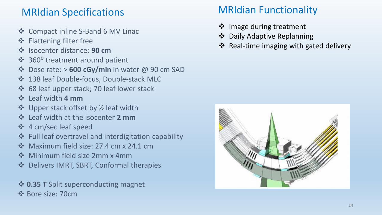
Compact inline S-Band 6 MV Linac Flattening filter free Isocenter distance: 90 cm 360⁰ treatment around patient Dose rate: > 600 cGy/min in water @ 90 cm SAD 138 leaf Double-focus, Double-stack MLC 68 leaf upper stack; 70 leaf lower stack Leaf width 4 mm Upper stack offset by ½ leaf width Leaf width at the isocenter 2 mm 4 cm/sec leaf speed Full leaf overtravel and interdigitation capability Maximum field size: 27.4 cm x 24.1 cm Minimum field size 2mm x 4mm Delivers IMRT, SBRT, Conformal therapies
0.35 T Split superconducting magnet Bore size: 70cm
MRIdian Specifications MRIdian Functionality
Image during treatment Daily Adaptive Replanning Real-time imaging with gated delivery
14

Minimal perturbations of the dose distributions and surface doses
Dose distortion from Electron Return Effect (ERE) is clinically insignificant 𝑟 ∝ Τ1 𝐵𝑜: TPS, MC calculation, takes into account the effect even if small
No SAR (tissue heating) issues from repeated MRI
Sub-millimeter chemical shift and susceptibility distortions ∆𝑥 ∝ 𝐵0
Short T1 tissue relaxation time enables fast MRI
MRIdian Linac setup images and cine show no artifacts
MRIdian : Advantages of 0.35T MRI for RT
15

Unity - ElektaIs an integrated magnetic
resonance (MR)–guided
radiation therapy (RT)
system
designed to provide
simultaneous MR
imaging(MRI)
&
external-beam RT
at the same isocenter.
16

The accelerator is modified by replacing various steel
components by non-ferromagnetic copies.
Unity MRI is composed by a 6 MV Elekta (Crawley, UK)
accelerator mounted on a ring around a modified 1.5 T
Philips Achieva (Best, The Netherlands) MRI system.
SAD =1,5 m
The Philips Achieva is replaced by the the 1.5 T magnet built
by Magnex (Oxford, UK) modified to make the system
compatible with a linear accelerator in perpendicular
configuration
A ring gantry, which holds all the beam generating components,
such as the magnetron, waveguide, a standing wave linear
accelerator, and the Multi Leaf Collimator (MLC), is positioned
around the cryostat.
1,5 MRI
System
6MV
LINAC
Split
Gradient coils
Superconducting
coils
17

The active shielding of the magnet has been modified to
create a torus of near zero magnetic field around the magnet
at the location of the sensitive electronic components,
waveguide, and the gun of the Linac.
The cryostat has been integrated into the Faraday cage to
minimize radiofrequency interference of the Linac
components on MR signal acquisition.
The cryostat and B0 coils have been modified to minimize
beam attenuation, and the gradient coils are physically split,
which creates a radiation window of 22 cm at isocenter.
The radiation beam travels through the closed-bore MRI before it enters the patient.
The system is equipped with a 2 4 channel radiolucent receive array (coil), with electronic
components placed outside the radiation window to minimize attenuation and radiation induced
currents that may impact image quality18

19

20

Compact inline S-Band 6 MV Linac Flattening filter free Isocenter distance: 90 cm 360⁰ treatment around patient Dose rate: > 600 cGy/min in water @ 90 cm SAD 138 leaf Double-focus, Double-stack MLC Leaf dimension 4 mm /2 mm at isocenter 4 cm/sec leaf speed Full leaf overtravel and interdigitation capability Maximum field size: 27.4 cm x 24.1 cm Minimum field size 2mm x 4mm Delivers IMRT, SBRT, Conformal therapies
0.35 T Split superconducting magnet Bore size: 70cm
MRIdian Linac Specifications Unity Linac Specifications
6 MV Linac Flattening filter free Isocenter distance: 143,5 cm 360⁰ treatment around patient Dose rate: > 450 cGy/min at dmax & SAD MLC Agility leaf dimension =7 mm at the isocenter 6 cm/sec leaf speed Full leaf overtravel and interdigitation capability Maximum field size: 22 cm x 57,4 cm Minimum field size 5mm x 5mm Delivers IMRT, SBRT, Conformal therapies
1,5 T Split superconducting magnet Bore size: 70cm
21

The direction of the main magnetic field must be verified as it determines the
direction of dose kernel tilt and the electron return effect (ERE).QC _Hybrid test
Measure the B0 homogeneity as a function of gantry angle. Because the
gantry contains large amounts of ferromagnetic material, the gantry can
introduce spatially varying offsets to the B0 field, which could lead to image
artifacts.
RF interference produced by the Linac is tested.
Noise only scans (i.e., images acquired without RF excitation) are
acquired
1) with the Linac turned off,
2) with the magnetron turned on, but without radiation,
3) with moving MLCs
Additionally, phantom scans and noise only scans were performed
during irradiation of various field sizes to test the effect of pulsed
radiation on the receiver coils
22

23
Suggested Test

B0 homogeneity as a function of gantry angle
24
The B0 field maps, with and without active shimming, at various gantry angles
MRL#4 shows an apparent linear field offset that rotates with the gantry angle when no active
shimming is performed (top row, panel a).
The dependency is largely mitigated after active shimming (top row, panel b).
MRL#3 (second row) : effect of gantry angle was not observed for, excellent B0 homogeneity with
and without active shimming.

Inter- and intra-fractional organ changes entail major problems for the safe delivery of intended doses in
EBRT for tumours located in the abdominal and pelvic region, especially for hypofractionated schemes.
Variability in rectum and bladder filling has been observed for patients treated for prostate cancer
lower biochemical tumour control was reported for patients with larger rectum volumes at the time of the
CT simulation presumably because of geographic misses.
Mean prostate displacements of up to 9mm between fractions with the largest deviation found in the
anterior-posterior (AP) direction are reported by interfractional prostate variability investigations
Seminal vesicles, included in the target volume for intermediate and high risk disease patients, are
subjected to even larger inter-fractional shifts than the prostate
Intra-fractional rotations and deformations of prostate and seminal vesicles because of variable rectal
filling have been reported.
#1 Clinical applications MRIdian Viewray
25

MR-guided radiation therapy (MRgRT) allows for superior visualization of the prostate, base of the
seminal vesicles and adjacent OARs such as the rectum and bladder prior to- and during treatment
delivery.
Proper management of inter- and intra-fractional variations allows for treatment with small uncertainty
margins and in combination with daily plan re-optimization may result in relevant reductions of doses to
normal tissues
.
Daily image-guided radiotherapy (IGRT) improves the precision and accuracy of treatment delivery for
prostate cancer
26

S.U. Tetar, et al. “Clinical implementation of magnetic resonance imaging guided adaptive radiotherapy for localized prostate cancer” Physics and Imaging in Radiation Oncology 9 (2019)
• MR##
• Rigid Registration MR## & MR1
• Contouring CTV
• Deformable registration MR## & MR
• CT Deformable registration
• Deformed electron density map.-pseudo CT
• Predicted Plan
• Adapted Plan
• MC QA
• CT scan
• MR1 scan
• FISP short TR and TE=TR/2
• TR/TE =3,37/1,45 FA 60°
• CT-MRI Deformable registration
• Contouring
• Map density registration
• MC Baseline plan
•Cine acquisition
•Only sagittal plane
•CTV out of PTV more than %
•Beam off- beam on
Simulation Each fractions: on line adaptive Treatment
Viewray -workflow
27

Baseline Predicted Adapted
28

Adaptive QA is performed with an independent Monte Carlo dose calculation Magnetic field can be included in calculation Gamma Analysis is reported Process take 1-2 minutes
29

30

31

32

Henke LE, et al., Magnetic Resonance Image-Guided Radiotherapy (MRIgRT): A 4.5-Year Clinical Experience,Clinical Oncology (2018)
Clinical experience at the Radiation Oncology Department Washington University St. Louis
33

34

35

36

37
Acknowledgements
Dr. Marco Fusella Medical Physics Department IOV
Dr.ssa Ludovica Mei Radiustech- Viewray
Dr. GianLuca degli Stefani Elekta S.p.A
.
38

This technology offers improved soft-tissue visualisation daily imaging and intra-fraction real-time imaging without added radiation exposure adaptive radiotherapy (ART) to adjust for anatomical changes
WHY MRIgRT
39