prevention of significant air quality deterioration review ... · pdf fileprevention of...
TRANSCRIPT

Prevention of Significant Air Quality Deterioration Review Owens Corning – Cordele
Located in Crisp County, Georgia
PRELIMINARY DETERMINATION SIP Permit Application No. 15839
May 2005
State of Georgia Department of Natural Resources Environmental Protection Division
Air Protection Branch
Stationary Source Permitting Program (SSPP)
Prepared by
Brian Massengale – Combustion Unit
Modeling Approved by: Richard Monteith & Jim Stogner
Data and Modeling Unit
Reviewed and Approved by:
John Yntema – Unit Manager, Combustion Heather Abrams – Program Manager, SSPP
Ron Methier – Chief, Air Protection Branch

TABLE OF CONTENTS
SUMMARY ........................................................................................................................................................................................1
1.0 INTRODUCTION...................................................................................................................................................................2
2.0 PROCESS DESCRIPTION....................................................................................................................................................2
3.0 REVIEW OF APPLICABLE RULES AND REGULATIONS ..........................................................................................4
State Rules............................................................................................................................................................................................4
Federal Rule - PSD ..............................................................................................................................................................................4
Federal Rule – 40 CFR 60 Subpart PPP..............................................................................................................................................6
Federal Rule – 40 CFR 63 Subpart NNN............................................................................................................................................7
State and Federal – Startup and Shutdown and Excess Emissions......................................................................................................7
Federal Rule – 40 CFR 64- Compliance Assurance Monitoring.........................................................................................................7
4.0 CONTROL TECHNOLOGY REVIEW...............................................................................................................................8
GLASS MELTING FURNACE CG101 – PARTICULATE MATTER.............................................................................................8
Summary – Control Technology Review for PM from Electric Glass Melting Furnace CG101......................................................11
RAW MATERIAL HANDLING and PRODUCT FINISHING OPERATIONS CG100 – PARTICULATE MATTER................11
Summary – Control Technology Review for PM from Raw Material Handling and Product Packaging Operations......................12
MANUFACTURING LINES CG-1 and CG-2 – PARTICULATE MATTER.................................................................................13
Summary – Control Technology Review for PM from Bonded (CG-1) and Unbonded (CG-2) Fiberglass-Manufacturing Lines ..15
GLASS MELT FURNACE CG101 and BONDED & UNBONDED FIBERGLASS MANUFACTURING LINES CG-1 & CG-2 – NITROGEN OXIDES.....................................................................................................................................................................16
Summary – Control Technology Review for NOX from Glass Melt Furnace CG101 and Bonded & Unbonded Manufacturing Lines CG-1 & CG-2...........................................................................................................................................................................18
GLASS MELT FURNACE CG101, FORMING CG104, CURING CG105 and MANUFACTURING LINE CG-2 – CARBON MONOXIDE......................................................................................................................................................................................18
Summary – Control Technology Review for CO from Furnace CG101, Forming CG104, Curing CG105, and Unbonded Manufacturing Line CG-2..................................................................................................................................................................20
FURNACE CG101 and MANUFACTURING LINES CG-1 & CG-2 – VOLATILE ORGANIC COMPOUNDS........................20
Summary – Control Technology Review for VOC from Furnace CG101 and Bonded and Unbonded Manufacturing Lines CG-1 & CG-2...............................................................................................................................................................................................24
5.0 TESTING AND MONITORING REQUIREMENTS .......................................................................................................25
6.0 AMBIENT AIR QUALITY REVIEW ................................................................................................................................27
7.0 ADDITIONAL IMPACT ANALYSES ...............................................................................................................................33
8.0 EXPLANATION OF DRAFT PERMIT CONDITIONS ..................................................................................................34
APPENDICES
APPENDIX A Draft Title V Operating Permit APPENDIX B PSD Permit Application and Supporting Data APPENDIX C EPD’s PSD Dispersion Modeling and Air Toxics Assessment Review

PSD Preliminary Determination Page 1 of 38
SUMMARY The Environmental Protection Division (EPD) has reviewed the Owens Corning – Cordele (OC) facility’s application for a permit to construct and operate a wool fiberglass manufacturing facility in Cordele, Georgia (Crisp County). The project involves the construction and operation of a green field wool fiberglass insulation manufacturing facility. This facility will produce light density building insulation products. The proposed project involves the installation of a cold -top electric Furnace CG101 with natural gas backup burners. Particulate matter emissions from the furnace will be controlled via a batch wetting system. Nitrogen Oxide (NOX) emissions will be limited by controlling the amount of sodium nitrate added to the mixed glass batch. The proposed project also involves the construction and operation of two fiberglass manufacturing lines; a bonded line CG-1 and an unbonded line CG-2. These manufacturing lines will operate using both electrical and natural gas heating. A proprietary in-line washing system will be used to control particulate matter emissions created in the bonded and unbonded forming sections (CG104 and CG204 respectively). Exhaust from the curing oven (CG105) on the bonded line will be routed through burner sections and screen filters and will then be routed to a thermal incinerator for VOC and condensable particulate matter control, before exhausting to the mixing chamber where it will be combined with the untreated exhaust from the bonded forming section, and then emitted to the atmosphere. The Cooling Section CG106 will pull air through the cured fiberglass mat and gases will be ducted to a low-pressure drop wet scrubber for particulate matter control. A raw material delivery/handling and binder preparation system (CG100) will be installed. Baghouses will be used to control particulate matter from the raw material handling and batch charging operations. Fabrication, reclaim, and packaging systems, controlled by penclones, are proposed for the Bonded Line CG-1. A packaging system, controlled by a penclone, is also proposed for the Unbonded Line CG-2. The collected fiberglass material will be routed to the proposed repack system for use as loose fill insulation. These units are viewed essentially as fugitive emission sources, since the penclones will exhaust within the building. The OC facility is located in Crisp County, which is classified as “attainment” or “unclassifiable” for SO2, PM10, NOX, CO, and ozone in accordance with Section 107 of the Clean Air Act, as amended during August 1977. This facility is located within 200 km of three Class I Areas (Okefenokee NWR, Bradwell Bay Wilderness, and Saint Marks NWR). The EPD’s review of the data submitted by OC, related to the proposed facility, indicates that the project will be in compliance with all applicable state and federal air quality regulations. It is the preliminary determination of the EPD that the proposal provides for the application of Best Available Control Technology (BACT) for the control of PM, PM10, NOX, CO, and VOC as required by federal Prevention of Significant Deterioration (PSD) regulations found in 40 CFR 52.21(j). It has been determined, through approved modeling techniques, that the estimated emissions will not cause or contribute to a violation of any ambient air quality standard or allowable PSD increment. It has further been determined that the proposal will not cause impairment of visibility or detrimental effects on soils or vegetation. Any air quality impacts produced by project-related growth is predicted to be inconsequential. This Preliminary Determination concludes that an Air Quality Permit should be issued to Owens Corning – Cordele for the proposed new source. Various conditions will be made a part of the permit to construct and operate in order to ensure and confirm compliance with all applicable air quality regulations. A copy of the draft permit is included in Appendix A.
PSD Preliminary Determination Page 2 of 38
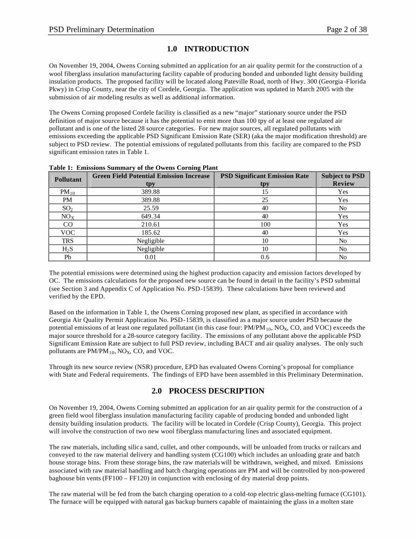
1.0 INTRODUCTION On November 19, 2004, Owens Corning submitted an application for an air quality permit for the construction of a wool fiberglass insulation manufacturing facility capable of producing bonded and unbonded light density building insulation products. The proposed facility will be located along Pateville Road, north of Hwy. 300 (Georgia -Florida Pkwy) in Crisp County, near the city of Cordele, Georgia. The application was updated in March 2005 with the submission of air modeling results as well as additional information. The Owens Corning proposed Cordele facility is classified as a new “major” stationary source under the PSD definition of major source because it has the potential to emit more than 100 tpy of at least one regulated air pollutant and is one of the listed 28 source categories. For new major sources, all regulated pollutants with emissions exceeding the applicable PSD Significant Emission Rate (SER) (aka the major modification threshold) are subject to PSD review. The potential emissions of regulated pollutants from this facility are compared to the PSD significant emission rates in Table 1. Table 1: Emissions Summary of the Owens Corning Plant
Pollutant Green Field Potential Emission Increase tpy
PSD Significant Emission Rate tpy
Subject to PSD Review
PM10 389.88 15 Yes PM 389.88 25 Yes SO2 25.59 40 No NOX 649.34 40 Yes CO 210.61 100 Yes
VOC 185.62 40 Yes TRS Negligible 10 No H2S Negligible 10 No Pb 0.01 0.6 No
The potential emissions were determined using the highest production capacity and emission factors developed by OC. The emissions calculations for the proposed new source can be found in detail in the facility’s PSD submittal (see Section 3 and Appendix C of Application No. PSD-15839). These calculations have been reviewed and verified by the EPD. Based on the information in Table 1, the Owens Corning proposed new plant, as specified in accordance with Georgia Air Quality Permit Application No. PSD-15839, is classified as a major source under PSD because the potential emissions of at least one regulated pollutant (in this case four: PM/PM10, NOX, CO, and VOC) exceeds the major source threshold for a 28-source category facility. The emissions of any pollutant above the applicable PSD Significant Emission Rate are subject to full PSD review, including BACT and air quality analyses. The only such pollutants are PM/PM10, NOX, CO, and VOC. Through its new source review (NSR) procedure, EPD has evaluated Owens Corning’s proposal for compliance with State and Federal requirements. The findings of EPD have been assembled in this Preliminary Determination.
2.0 PROCESS DESCRIPTION On November 19, 2004, Owens Corning submitted an application for an air quality permit for the construction of a green field wool fiberglass insulation manufacturing facility capable of producing bonded and unbonded light density building insulation products. The facility will be located in Cordele (Crisp County), Georgia. This project will involve the construction of two new wool fiberglass manufacturing lines and associated equipment. The raw materials, including silica sand, cullet, and other compounds, will be unloaded from trucks or railcars and conveyed to the raw material delivery and handling system (CG100) which includes an unloading grate and batch house storage bins. From these storage bins, the raw materials will be withdrawn, weighed, and mixed. Emissions associated with raw material handling and batch charging operations are PM and will be controlled by non-powered baghouse bin vents (FF100 – FF120) in conjunction with enclosing of dry material drop points. The raw material will be fed from the batch charging operation to a cold-top electric glass-melting furnace (CG101). The furnace will be equipped with natural gas backup burners capable of maintaining the glass in a molten state

PSD Preliminary Determination Page 3 of 38 during extended periods of power loss. PM emissions will be reduced via a batch wetting system and NOX emissions will be limited by controlling the amount of sodium nitrate added to the mixed glass batch. Molten glass exiting the furnace will flow via gravity through a primary conditioning channel (CG102) to the bonded line and a secondary conditioning channel (CG202) to the unbonded line. Each conditioning channel will feed its respective forehearth for the bonded line CG103 and unbonded line CG203, which in turn will deliver molten glass to the respective forming section natural gas fiberizers. The channels and forehearths will be heated electrically and will be sealed to minimize heat loss as well as minimize PM and metal HAP process emission from these sources. Bonded Line CG-1 The binder used in the bonded manufacturing process (CG-1) is an aqueous solution whose main active ingredient is a phenol/formaldehyde thermosetting resin. Other materials consist of water (fresh and/or reclaimed), dye, process oil, urea, silane, ammonia, etc. The bulk supplies for the binder material will be received by rail car and/or truck. Bulk supply materials will be drawn from storage and mixed to produce the binder. The binder is then transferred to storage for application in the forming section. Emissions from binder raw material storage, formulation, and delivery include VOCs, HAPs, and ammonia. In the forming section for the bonded manufacturing line (CG104), molten glass will pass through the natural gas-heated fiberizers. During this process, glass fibers will be made using a rotary spin process while a chemical binder is sprayed on the glass fibers. Fibers will then be attenuated to the desired diameter and broken into short lengths by blasts of air. The veil of fibers is then to be coated with a resin-based binder solution and formed into a pack on a horizontal conveyor. Air will be pulled through the fiberglass mat, pulling free water, binder overspray and loose fiber from the mat. An in-line low pressure-drop scrubber and tangential-entry cyclonic separator, used in series, will be used to remove fibers and water-entrained particles from the air flow to ensure functionality (minimize damage to) of the forming fans as well as to remove PM emissions from the forming zones. Water and wet scrap can be recycled, the scrap being used as a raw material in the melter and binder preparation process. Untreated exhausts from the bonded line forming fans will be combined with the air stream from the curing oven incinerator in the mixing chamber. Forming emissions include PM, VOC, HAP, NOX, SO2, CO and ammonia. After forming on the bonded line, the fiberglass pack will then be transferred to the curing oven (CG105). Combustion air will pass through the pack to drive off water and thermally cure the binder. Exhaust from the curing ovens will be routed through burner sections and screen filters which will function to keep the exhaust ducts and fans free of build-up, and will then be routed to a thermal incinerator (TO100) for VOC and condensable particulate matter control. As mentioned above, incinerator exhaust will be combined with uncontrolled exhaust from the bonded forming section in the mixing chamber, before being exhausted through a stack. The cured pack will enter the cooling section (CG106) where air will be drawn through the pack to cool it. The gases will be ducted to a low-pressure drop wet scrubber (SC100) for the reduction of PM emissions. The cooled fiber mat will be conveyed to the fabrication system (CG110) for trimming and final product packaging. Trimmed material is then conveyed to the reclaim system (CG111) and recycled. A vapor barrier facing is then applied to some products, using the paper applicator heater (CG108). Product specifications are printed and product is packaged using automatic bagging machines (CG109). Unbonded Line CG-2 The unbonded manufacturing line (CG204) will be similar to the bonded forming section. Molten glass will be formed into glass fibers. Instead of binder solution, silicone oil and silane will be applied in the unbonded forming section. Air is then to be pulled through the mat, collecting water and loose fiber. An in -line low pressure drop scrubber and tangential-entry cyclonic separator will be used to remove fibers and water-entrained particles, ensuring forming fan functionality and reducing the outlet PM emissions from the unbonded forming zones. Water and wet scrap can be recycled, the scrap being used as a raw material in the melter and binder preparation process. Exhausts from the unbonded line forming fans will not be treated before entering the atmosphere. Forming emissions will include PM, VOC, HAP, NOX, SO2, CO and ammonia. The mat from the unbonded forming section will then be processed through a hammer mill, before dropping product into a bagging system (CG211) as loose fill insulation. The printing system (CG207) is to be utilized to print product information on the product.

PSD Preliminary Determination Page 4 of 38
3.0 REVIEW OF APPLICABLE RULES AND REGULATIONS
State Rules Georgia Rules for Air Quality Control (Georgia Rule) 391-3-1-.03(1) requires that any person prior to beginning the construction or modification of any facility that may result in an increase in air pollution shall obtain a permit for the construction or modification of such facility from the Director upon a determination by the Director that the facility can reasonably be expected to comply with all the provisions of the Act and the rules and regulations promulgated thereunder. Georgia Rule 391-3-1-.03(8)(b) continues: no permit to construct a new stationary source or modify an existing stationary source shall be issued unless such proposed source meets all the requirements for review and for obtaining a permit prescribed in Title I, Part C of the Federal Act [i.e., Prevention of Significant Deterioration of Air Quality (PSD)], and Section 391-3-1-.02(7) of the Georgia Rules (i.e., PSD). Georgia Rule (b) “Visible Emissions” [391-3-1-.02(2)(b)] is a general rule that limits the opacity of emissions from any air contaminant source to less than 40%. Georgia Rule (b) applies to the raw material handling equipment (CG100), glass melting furnace (CG101), bonded forming section (CG104), bonded curing section (CG105), bonded cooling section (CG106), and unbonded forming section (CG204). Georgia Rule (e) “Particulate Emission from Manufacturing Processes” [391-3-1-.02(2)(e)], also known as the process weight rule, limits PM emissions based on the following equations:
For P= 30 ton/hr, E = 4.1 × P0.67 For P> 30 ton/hr, E = 55 × P0.11 - 40
Where
E = emission rate (lb/hr) and P = process input rate (ton/hr)
The raw material handling equipment (CG100) and glass melting furnace (CG101) are subject to Georgia Rule (e). Because the limits are based on the process input weight, which is not the basis for other limits, the limits are not subsumed by any other PM limits. Georgia Rule (g) “Sulfur Dioxide” [391-3-1-.02(2)(g)] applies to all fuel-burning sources. Paragraph 2 of the rule limits the percentage of sulfur, by weight, in the fossil fuel burned to 2.5 percent for fuel-burning sources with a maximum heat input less 100 MMBtu/hr. Paragraph 2 applies to the glass melting furnace (CG101), when power losses occur and the furnace is required to burn natural gas, as well as the fiberizers in the bonded and unbonded forming sections (CG104 and CG204), bonded curing ovens (CG105), and the incinerator (TO11), all of which burn natural gas. Georgia Rule (n) “Fugitive Dust” [391-3-1-.02(2)(n)] applies to any construction, operation, process, handling, transportation or storage facility that may result in fugitive dust. Georgia Rule (n) applies to the plant roads and material handling operations. Georgia Rule (oo) “Fiberglass Insulation Manufacturing Plants” [391-3-1-.02(2)(oo)] applies to particulate matter emissions from fiberglass insulation production lines, not including glass melting furnaces, fuel-burning equipment, raw material conveyance, storage or handling operations and handling, storage, or packaging equipment for the fiberglass insulation. Georgia Rule (oo) applies to the Bonded Line (CG-1) which includes the forming section (CG104), curing section (CG105), cooling section (CG106) and the Unbonded Line (CG-2), including the forming section (CG204). The subject emission units are not allowed to discharge into the atmosphere any gases containing PM in excess of 0.04 gr/dscf. All limits under Rule (oo) are equivalent to, or subsumed by, more stringent PSD BACT limits or NSPS Subpart PPP limits.
Federal Rule - PSD The regulations for PSD in 40 CFR 52.21 require that any new major source or modification of an existing major source be reviewed to determine the potential emissions of all pollutants subject to regulations under the Clean Air Act. The PSD review requirements apply to any new or modified source that belongs to one of 28 specific source categories having potential emissions of 100 tpy or more of any regulated pollutant, and to all other sources having

PSD Preliminary Determination Page 5 of 38 potential emissions of 250 tpy or more of any regulated pollutant. They also apply to any modification of a major stationary source that results in a significant net emission increase of any regulated pollutant. The PSD regulations require that any major stationary source or major modification subject to the regulations meet the following requirements:
• Application of BACT for each regulated pollutant that would be emitted in significant amounts; • Analysis of the ambient air impact; • Analysis of the impact on soils, vegetation, and visibility; • Analysis of the impact on Class I areas; and • Public notification of the proposed plant in a newspaper of general circulation.
Definition of BACT The PSD regulations require that BACT be applied to all regulated air pollutants emitted in significant amounts. Section 169 of the Clean Air Act defines BACT as an emission limitation reflecting the maximum degree of reduction that the permitting authority (in this case, EPD), on a case-by-case basis, taking into account energy, environmental, and economic impacts and other costs, determines is achievable for such a facility through application of production processes and available methods, systems, and techniques. In all cases, BACT must establish emission limitations or specific design characteristics at least as stringent as applicable New Source Performance Standards (NSPS). In addition, if EPD determines that there is no economically reasonable or technologically feasible way to measure the emissions, and hence to impose an enforceable emission standard, it may require the source to use a design, equipment, work practice, or operations standard or combination thereof, to reduce emissions of the pollutant to the maximum extent practicable. The BACT determination should, at a minimum, meet two core requirements. The first core requirement is that the determination follows a “top-down” approach. The second core requirement is that the selection of a particular control system as BACT must be justified in terms of the statutory criteria and supported by the record and must explain the basis for the rejection of other more stringent candidate control systems. EPD’s procedures for performing a top down BACT analysis are set forth in EPA’s Draft New Source Review Workshop Manual (Manual), dated October 1990. One critical step in the BACT analysis is to determine whether a control option is technically feasible. If a control is determined to be infeasible, it is eliminated from further consideration. The Manual applies several criteria for determining technical feasibility. The first is straightforward: if the control has been installed and operated by the type of source under review, it is demonstrated and technically feasible. For controls not demonstrated using this straightforward approach, the Manual applies a more complex approach that involves two concepts for determining technical feasibility: availability and applicability. A technology is considered available if it can be obtained through commercial channels. An available control is applicable if it can be reasonably installed and operated on the source type under construction. A technology that is available and applicable is technically feasible. The Manual provides some guidance for determining availability. For example, a control is generally considered available if it has reached the licensing and permitting stages of development. However, the Manual further provides that a source is not required to experience extended time delays or resource penalties to allow research to be conducted on new technologies. In addition, the applicant is not expected to experience extended trials learning how to apply a technology on a dissimilar source type. Consequently, technologies in the pilot-scale testing stages of development are not considered available for BACT. As mentioned before, the Manual also requires available technologies to be applicable to the source type under construction before a control is considered technically feasible. For example, deployment of the control technology on an existing source with similar gas stream characteristics is generally a sufficient basis for concluding technical feasibility. However, even in this instance, the Manual allows for an applicant to make a demonstration to the contrary. For example, an applicant could show that unresolved technical difficulties with applying a control to the source under consideration (e.g., size of the unit, location of the proposed site, and operating problems related to the specific circumstances of the source) make a control technically infeasible.
PSD Preliminary Determination Page 6 of 38 According to the Environmental Appeals Board (see In re: Kawaihae Cogeneration Project, 7 E.A.D. 107 at page 1996, EAB 1997), the section on “collateral environmental impacts” of a proposed technology has been interpreted to mean that “if application of a control system results directly in the release (or removal) of pollutants that are not currently regulated under the Act, the net environmental impact of such emissions is eligible for consideration in making the BACT determination.” The Appeals Board continues, “The Administration has explained that the primary purpose of the collateral impacts clause is…to temper the stringency of the technological requirements whenever one or more of the specified collateral impacts – energy, environmental, or economic – renders the use of the most effective technology inappropriate.” Lastly, the Appeals Board document states, “Unless it is demonstrated to the satisfaction of the permit issuer that such unusual circumstances exist, then the permit applicant must use the most effective technology.” The five steps of a top-down BACT review procedure identified by EPA in the BACT guidelines are listed below:
Step 1: Identify all control technologies Step 2: Eliminate technically infeasible options Step 3: Rank remaining control technologies by control effectiveness Step 4: Evaluate most effective controls and document results Step 5: Select BACT
Now that the PSD BACT standards have been defined, the next step is to review the remaining applicable federal requirements. This step will aid in citing the appropriate legal authority for each requirement in the PSD permit. This analysis will show that the PSD BACT standards represent the most stringent limits.
Federal Rule – 40 CFR 60 Subpart PPP Manufacturing lines CG-1 and CG-2 are rotary spin wool fiberglass insulation manufacturing lines that will be constructed after February 7, 1984. These units are, therefore, subject to NSPS Subpart PPP, Standard of Performance for Wool Fiberglass Insulation Manufacturing Plants. This standard sets limits for PM. Per §60.682, each affected manufacturing line may emit no more than 11.0 pounds of PM per ton of glass pulled. The potential PM emission rates for each of the proposed manufacturing lines total less than 11.0 pounds of PM per ton of glass pulled.1 As will be shown further, in Section 4.0 of the Control Technology Review, the PSD BACT limits are 8.79 lb/ton of glass pulled for the bonded line and 4.0 lb/ton of glass pulled for the unbonded line. Therefore, the Subpart PPP PM limit of 11.0 lb/ton of glass pulled is subsumed for both manufacturing lines CG-1 and CG-2 by the more stringent BACT limits. Compliance with these limits will be monitored with continuous parametric monitoring systems and by initial performance testing. Monitoring requirements for wet scrubbers are included under §60.683. The proposed facility will operate low pressure drop in-line wet scrubbers and tangential cyclonic separators in series on each forming zone, resulting in PM emission reductions. In addition, a low pressure drop wet scrubber will be installed on the bonded line cooling section to limit PM emissions below the BACT limit (0.95 lb/ton of glass pulled). These control devices are subject to the monitoring requirements under Subpart PPP. Specifically, the NSPS requires monitoring for gas pressure drop and scrubbing liquid flow rate, at least every four hours, across each scrubber. Records of measurements must be maintained on-site. A pressure drop monitoring device must be installed in accordance with manufacturer requirements and be accurate to within 1 inch water gauge. The flow rate monitor device is to be certified by the manufacturer within 5% over its operating range. The monitoring devices must be recalibrated each quarter. Per NSPS requirements, a performance test must be conducted within 60 days after each manufacturing line achieves maximum production but not later than 180 days after initial startup. The required monitoring parameters must be measured every 30 minutes during the performance test. For this test to be valid, the product with the highest loss on ignition (LOI) must be produced by the facility while conducting the performance test. At 30 minute intervals during each 2-hour test run of each PM performance test, if controlled by a wet scrubber, and at least every 4 hours thereafter, the Permittee shall record the measurements required by 60.683(a). From then on, compliance shall be determined using the particulate matter and glass pull rate equation in 60.685(c).
1 BACT limits for the bonded line: The mixing chamber (forming and curing) emission limit of 7.84 lb PM/ton glass pulled and the cooling section emission limit of 0.95 lb PM/ton glass pulled, total 8.79 lb PM/ton glass pulled. The BACT limit for the unbonded line (the forming section) is an emission limit of 4 lb PM/ton glass pulled.
PSD Preliminary Determination Page 7 of 38 Exceedances are defined as any monitoring data that is less than 70% of the lowest value or greater than 130% of the highest value for each parameter recorded during the most recent performance test. A semi-annual report describing all control device operating parameter exceedances, any corrective actions taken as a result of the exceedances, and including documentation of quarterly monitoring device calibrations, must be submitted.
Federal Rule – 40 CFR 63 Subpart NNN The proposed Cordele facility is a major hazardous air pollutant (HAP) source subject to NESHAP Subpart NNN, National Emission Standards for Hazardous Air Pollutants for Wool Fiberglass Manufacturing. The NESHAP establishes standards for the glass melting furnace and rotary spin wool fiberglass manufacturing line producing bonded wool fiberglass. Accordingly, the unbonded manufacturing line (CG-2) is not subject to requirements of NESHAP Subpart NNN. Subpart NNN emission standards are 0.5 pounds of filterable PM per ton of glass pulled for the new glass melting furnace (CG101) and 0.8 pounds of formaldehyde per ton of glass pulled for the bonded rotary spin manufacturing line (CG-1). The glass melt furnace will demonstrate compliance with this PM limit using a continuous parametric monitoring system, and monitoring the batch wetting water flow rate and glass pull rate; these must be implemented by a Quality Improvement Plan (QIP) consistent with the Compliance Assurance Monitoring (CAM) provisions. An initial performance test is required. Compliance with the formaldehyde limit for the bonded rotary spin manufacturing line must be monitored with a continuous parametric monitoring system (monitoring operating temperature of the fire -box in the incinerator, free-formaldehyde content of each resin shipment received and used in the formulation of the binder, formulation of each binder batch, and recording every 8 hours the loss on ignition (LOI) and product density of each bonded fiberglass product). Initial performance testing is required.
State and Federal – Startup and Shutdown and Excess Emissions Excess emission provisions for startup, shutdown, maintenance, and malfunction are provided in Georgia Rule 391-3-1-.02(2)(a)7. Excess emissions from the units associated with this proposed new source would most likely result from a malfunction of the associated control equipment. The facility cannot anticipate or predict malfunctions. However, the facility is required to minimize emissions during periods of startup, shutdown, and malfunction.
Federal Rule – 40 CFR 64- Compliance Assurance Monitoring 40 CFR 64, regarding Compliance Assurance Monitoring (CAM), applies to pollutant-specific emission units (PSEUs) as defined in the subpart. PSEUs are units for which there exists an emission standard, for which there is a Part 64 control device, and for which the pre-control potential emission rate is equal to or greater than 100 percent of the major source threshold. The frequency of data collection under Part 64 depends on whether the controlled potential to emit exceeds 100 tpy, in which case it is considered to be a “large PSEU.” Additionally for large PSEUs, CAM Plans must be prepared with Title V permit applications submitted after April 20, 1998. The facility will be a major source subject to permitting requirements of Title V; a Title V application will be due no later than 12 months after the commencement of operations at the facility. CAM applicability and CAM requirements will be addressed in the Title V application submittal.

PSD Preliminary Determination Page 8 of 38
4.0 CONTROL TECHNOLOGY REVIEW
GLASS MELTING FURNACE CG101 – PARTICULATE MATTER Step 1: Identify all Control Technologies The currently available particulate matter (PM) controls include baghouses (fabric filters), dry electrostatic precipitators (ESPs), wet ESPs (WESPs), high efficiency wet scrubbers (particularly venturi scrubbers), cyclones and batch wetting systems. Fabric filters Dry filtration is a common method for removing dry particulate matter from many types of industrial gas streams. A fabric filter unit consists of one or more isolated compartments containing rows of fabric filter bags or tubes. Particle-laden gas passes up (usually) along the surface of the bags, then radially through the fabric. Particles are retained on the upstream face of the bags, while the cleaned gas stream is vented to the atmosphere. The filter is operated cyclically, alternating between relatively long periods of filtering and short periods of cleaning. During cleaning, dust that has accumulated on the bags is removed from the fabric surface by some mechanical means and deposited in a hopper for subsequent disposal. Fabric filters are reusable filters made of cotton, Dacron®, Fiberglas®, Teflon®, Nome x®, polypropylene, polytetrafluoroethylene (PTFE), etc. Cleaning is done by sonic vibration, shaking, reversing the airflow, or pulsing the airflow. Fabric filters will collect particle sizes ranging from submicron to several hundred microns in diameter at efficiencies generally in excess of 99 percent. The dust cake collected on the fabric is primarily responsible for the effectiveness of such units. Gas temperatures up to about 500 °F, with surges to about 550 °F, can be accommodated routinely, depending on bag material. Most of the energy used to operate the system is due to pressure drop across the bags and losses through associated hardware and ducting. Typical values of pressure drop range from about 5 to 20 inches of water. Fabric filters are used where high-efficiency particle collection is required. Limitations are imposed by gas characteristics (temperature, moisture level, and corrosivity) and particle characteristics (primarily stickiness and abrasiveness) that affect the fabric or its operation. Electrostatic Precipitator An electrostatic precipitator (ESP) is a particle control device available in a variety of types including plate-wire, flat plate, tubular, wet, and two-stage precipitators. High voltage electrodes impart a negative charge to the particles entrained in the exhaust gas stream. The particles are given an electrical charge by forcing them to pass through a corona, a region in which gaseous ions flow. These negatively charged particles are then attracted to a grounded collecting surface, which is positively charged. The cleaned gas then exits the ESP. Inside the ESP, the particles build up on the collecting plates. Once the particles are collected on the plates, they must be removed from the plates without reentraining them into the gas stream. This is accomplished by rapping the plates at periodic intervals, causing the agglomerated particles to drop or slide down into a hopper, from which they are evacuated. In the case of wet ESPs, a liquid wash down collects the particulates and wet sluicing is used to remove the particles. Dry ESPs are generally used to control PM emissions from dry exhaust streams; while WESPs are commonly employed on wet exhaust streams that feature high humidity and/or entrained droplets and can handle some stickiness. Control efficiencies for dry ESPs used in the fiberglass manufacturing industry range up to 95%. WESPs regularly achieve approximately 90% control of filterable particulate matter in similar applications. Scrubber In wet scrubbing, an atomized liquid, usually water, is used to capture particulate dust or increase the size of aerosols. The particles can be captured by either the liquid or by the scrubber surface and then washed off by the liquid. Wet scrubbers have some unique characteristics lending themselves to particulate control. Since the captured particles are trapped in a liquid, reentrainment is avoided and the trapped particles can easily be removed from the collection device. In comparison to fabric filters and ESPs, scrubbers are smaller and more compact. They are particularly useful in the removal of PM when the waste gas stream (1) is sticky and/or hygroscopic, (2) is combustible or corrosive; (3) contains particles that are difficult to remove in their dry form, (4) has particles with high moisture content, (5) contains particles and soluble gases, or (6) has exhaust gases that are at elevated temperatures, generally ranging up to 750 °F, where cooling of the gas is needed. Removal efficiencies and the operational reliability of wet scrubbers are highly dependent on the exhaust stream being treated. OC anticipates that the best performance from any scrubber could range from 70 – 90% for the production units in their fiberglass

PSD Preliminary Determination Page 9 of 38 manufacturing line. Scrubber systems are generally more expensive to purchase and operate than dry filtration. However, they can often be operated more easily than more sophisticated types of particulate removal devices. Cyclone A cyclone imparts centrifugal force on the gas stream to separate the particulate matter from the carrier gas. The incoming gas enters the cyclone, most commonly in a tangential direction, and is forced in a circular motion down the device, where the gas turns and spirals up through the center of the cyclone tube and out the top of the device. The particles would be propelled outward, sliding on the inside walls and falling to the bottom where they can be removed. Cyclones are generally not adequate to meet stringent air pollution regulations, but are often used as precleaners for more expensive and efficient control devices or in process applications for material recovery. The control efficiency range for conventional single cyclones is estimated to be 70-90% for PM, 30-90% for PM10, and 0-40% for PM2.5. Batch Wetting System A batch wetting system is utilized to add moisture to the mixed batch ingredients charged into the glass melting furnace. This increases the weight of the crust that sits on top of the molten glass and makes the crust a marginally more effective condenser of batch volatiles. The batch wetting system also provides emissions control by minimizing PM emissions from the furnace by reducing the amount of fugitive material emitted.
Option 1: Dry Filtration (Baghouse) Option 2: Dry Electrostatic Precipitator (ESP) Option 3: Wet Electrostatic Precipitator (WESP) Option 4: Wet Scrubber Option 5: Cyclones Option 6: Batch wetting system
Step 2: Eliminate Technically Infeasible Options A review of the RBLC database shows that a fabric f ilter was installed as BACT on a Johns Manville electric melter. OC also has experience with fabric filters on cold-top electric furnaces similar to the proposed furnace. However, due to the amount of moisture in the exhaust streams of the electric furnaces and the hygroscopic nature of the exhausted dust, OC has been unable to operate these units without substantial difficulties, including clogging and tearing of the bags. Minimizing these problems would require the preheating of the furnace exhaust stream to increase its temperature to a level that is comfortably greater than its dew point before entering the baghouse. Because the RBLC database contains fabric filter control as BACT in one instance, OC has considered fabric filters, including sufficient preheating, in this BACT analysis for the cold-top electric furnace. A dry ESP is not well suited for low temperature, humid exhaust streams that contain low levels of hydroscopic, uncontrolled PM, such as is characteristic of the glass melting furnace exhaust stream. A review of the RBLC database shows that dry ESPs have been installed on melt furnaces at other fiberglass manufacturing facilities. However, these dry ESPs are only installed on melt furnaces that are heated via natural gas combustion and have exhaust streams with high levels of uncontrolled PM and elevated temperatures (greater than 400 °F) which are well above the anticipated dewpoint. Due to the physical and chemical nature of the PM, the furnace exhaust stream would have to be preheated before entering a dry ESP. OC will consider installation of a dry ESP on the furnace exhaust stream, with sufficient preheating, in this BACT analysis. A conservative maximum control efficiency of 95% will be used in this analysis.2 A WESP is not well suited for the glass melting furnace exhaust stream. When contacted with additional water, PM within the furnace exhaust stream forms a thick mud that would clog the collection plates of a WESP. This would create difficulty in removing the collected solids from the control device and would not allow the collected solids (batch ingredients) to be recycled back to the batch house for remixing, as the water content would be much too great. As a result, installation of a WESP is deemed technically infeasible for the glass melting furnace and will not be considered further in this BACT analysis. As discussed for the WESP, introducing water to the glass melting furnace exhaust stream would form a thick mud that would clog a wet scrubber and would not allow the collected PM (batch ingredients) to be recycled back to the
2 Maximum efficiency is based on BACT determination for CertainTeed Corporation in Kansas City, KS.

PSD Preliminary Determination Page 10 of 38 batch house for remixing. As a result, installation of a wet scrubber on the glass melting furnace exhaust stream is deemed technically infeasible and will not be considered further in this BACT analysis. Cyclones are unable to handle sticky PM, such as is characteristic of the glass melting furnace exhaust stream. Therefore, cyclones are technically infeasible for these operations. A batch wetting system is already proposed to be utilized to add moisture to the mixed batch ingredients charged into the glass melting furnace. This increases the weight of the crust that sits on top of the molten glass and enhances its ability to condense glass batch volatiles. The batch wetting system also minimizes PM emissions generated during batch charging into the furnace. Therefore, batch wetting systems are viewed as a control option for the cold-top electric furnace and will be considered further in this BACT analysis. Step 3: Ranking Remaining Control Technologies by Control Effectiveness Baghouses are considered the most effective means of controlling PM from an electric glass-melting furnace. OC’s process already uses a batch wetting system, increasing the moisture of the exhaust stream, which would cause clogging and tearing of the bags and prevents efficient use of baghouses. Other technically viable technologies would also likely have difficulty with an exhaust stream high in moisture. Table 2: Ranking of PM10 Control Technology for the Glass Melt Furnace
Control Technology Ranking Control Technology Control Efficiency 1 Fabric filter (with preheater) ~99% 2 Dry ESP (with preheater) ~95% 3 Batch wetting system Variable*
*Dependent on the moisture content of the controlled PM Step 4: Evaluate Most Effective Controls and Document Results Fabric Filter A fabric filter has the highest control efficiency of any of the particulate matter control options for the furnace, and therefore, according to the “top-down” approach, must be considered first. In general, fabric filters can be installed on sources that can be vented through a duct; controlled emission levels of 0.01 gr/dscf can be achieved. A conservative cost analysis was performed to evaluate the economic impact of installation of a fabric filter on the total furnace exhaust stream. Operationally, though OC will likely install at least two stacks on the cold-top electric furnace to ensure uniform airflow across the batch charging slot and batch crust, the exhaust streams for all stacks would likely be combined before flowing into a potential control device. Preheating of the air stream would be required prior to entering the fabric filter. Table 3 below summarizes the cost effectiveness evaluation for a fabric filter, including preheating, on the furnace stack. The evaluation conservatively assumes that the fabric filter will control 99% of total PM, including both filterable and condensable portions. The resulting cost effectiveness is estimated to be $22,355 per ton of PM removed. Accordingly, installation of a fabric filter for PM control from the furnace is not considered an economically feasible option. Dry Electrostatic Precipitator An ESP with preheating is a technically feasible option for the furnace. A new ESP is predicted to achieve up to 95% control efficiency for PM for such operation. The assumptions made for the ESP are similar in nature to those made for the fabric filter (e.g., one device for the total furnace exhaust stream and pre-heating the air). Table 3 below summarizes the cost effectiveness evaluation for an ESP on the furnace exhausts. The evaluation conservatively assumes that the ESP will control 95% of total PM, including both filterable and condensable portions. The resulting cost effectiveness is estimated to be $14,133 per ton of PM removed. Accordingly, given the conservative assumptions detailed, installation of an ESP for PM control from the furnace is not considered an economically feasible option. Batch Wetting System A batch wetting system is a technically feasible control option for the furnace. The control efficiency of a batch wetting system is dependent on the moisture content of the batch materials. OC proposes to install a batch wetting

PSD Preliminary Determination Page 11 of 38 system on the furnace which will minimize the amount of batch ingredients lost as fugitive emissions which are ducted through the stack. Table 3: Summary of PM Control Costs for Glass Melt Furnace
Control Technology
Capital Cost ($)
Operating Cost ($)
Cost Effectiveness ($/ton removed)
Fabric Filter 1.66 million 510,938/yr 22,355 ESP 1.66 million 309,975/yr 14,133
Step 5: Select BACT The RBLC database lists several entries for PM and PM10 control using a baghouse for an electric furnace. However, as can be seen in the table, a baghouse is not cost effective in this proposed plant. On the other hand, OC’s proposed PM limit without add-on controls is in the range of controlled furnaces in RBLC database and the cost of the batch wetting system is reasonable. OC will comply with the NESHAP Subpart NNN limit of 0.5 lb/ton of glass pulled for filterable PM (0.58 lb/ton of glass pulled for total PM, including condensibles) using a batch wetting system determined to be BACT. This limit is also lower than that of Georgia Rule (e) limit for PM at the maximum production rate. Conclusion – PM Control The EPD has determined that OC’s proposal to use a batch wetting system to minimize PM emissions constitutes BACT. The BACT emission limit has been established as 0.50 lb/ton of glass pulled, as proposed by OC. Compliance with the PM limit must be demonstrated through performance testing and by monitoring parameters of the associated batch wetting system.
Summary – Control Technology Review for PM from Electric Glass Melting Furnace CG101 To fulfill the PSD permitting requirements for PM, OC conducted a BACT analysis for the CG101 Electric Glass-Melt Furnace. The BACT selection for the CG101 Furnace is summarized in Table 4. The emission limit selected is representative of previous PSD BACT determination levels published in the RBLC database. Table 4: BACT PM Summary for Electric Glass Melting Furnace CG101
Pollutant Control Technology Proposed BACT Limit Filterable PM Batch Wetting System 0.50 lb/ton glass pulled
RAW MATERIAL HANDLING and PRODUCT FINISHING OPERATIONS CG100 – PARTICULATE MATTER
Step 1: Identify all Control Technologies The currently available particulate matter (PM) controls include baghouses (fabric filters), dry electrostatic precipitators (ESPs), wet ESPs (WESPs), high efficiency wet scrubbers (i.e., venturi scrubbers) and cyclones. The theory and operation of each of these control technologies is discussed in detail in the Electric Glass Melting Furnace CG101 section BACT analysis.
Option 1: Dry Filtration (bin vents) Option 2: Dry Electrostatic Precipitator Option 3: Wet Electrostatic Precipitator Option 4: Wet Scrubber Option 5: Cyclones
Step 2: Eliminate Technically Infeasible Options All of the controls are technically feasible.
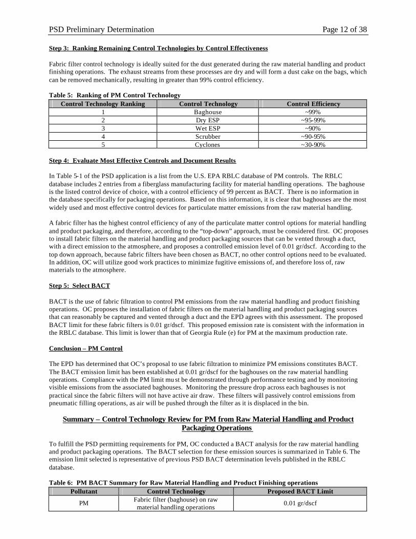
PSD Preliminary Determination Page 12 of 38 Step 3: Ranking Remaining Control Technologies by Control Effectiveness Fabric filter control technology is ideally suited for the dust generated during the raw material handling and product finishing operations. The exhaust streams from these processes are dry and will form a dust cake on the bags, which can be removed mechanically, resulting in greater than 99% control efficiency. Table 5: Ranking of PM Control Technology
Control Technology Ranking Control Technology Control Efficiency 1 Baghouse ~99% 2 Dry ESP ~95-99% 3 Wet ESP ~90% 4 Scrubber ~90-95% 5 Cyclones ~30-90%
Step 4: Evaluate Most Effective Controls and Document Results In Table 5-1 of the PSD application is a list from the U.S. EPA RBLC database of PM controls. The RBLC database includes 2 entries from a fiberglass manufacturing facility for material handling operations. The baghouse is the listed control device of choice, with a control efficiency of 99 percent as BACT. There is no information in the database specifically for packaging operations. Based on this information, it is clear that baghouses are the most widely used and most effective control devices for particulate matter emissions from the raw material handling. A fabric filter has the highest control efficiency of any of the particulate matter control options for material handling and product packaging, and therefore, according to the “top-down” approach, must be considered first. OC proposes to install fabric filters on the material handling and product packaging sources that can be vented through a duct, with a direct emission to the atmosphere, and proposes a controlled emission level of 0.01 gr/dscf. According to the top down approach, because fabric filters have been chosen as BACT, no other control options need to be evaluated. In addition, OC will utilize good work practices to minimize fugitive emissions of, and therefore loss of, raw materials to the atmosphere. Step 5: Select BACT BACT is the use of fabric filtration to control PM emissions from the raw material handling and product finishing operations. OC proposes the installation of fabric filters on the material handling and product packaging sources that can reasonably be captured and vented through a duct and the EPD agrees with this assessment. The proposed BACT limit for these fabric filters is 0.01 gr/dscf. This proposed emission rate is consistent with the information in the RBLC database. This limit is lower than that of Georgia Rule (e) for PM at the maximum production rate. Conclusion – PM Control The EPD has determined that OC’s proposal to use fabric filtration to minimize PM emissions constitutes BACT. The BACT emission limit has been established at 0.01 gr/dscf for the baghouses on the raw material handling operations. Compliance with the PM limit mu st be demonstrated through performance testing and by monitoring visible emissions from the associated baghouses. Monitoring the pressure drop across each baghouses is not practical since the fabric filters will not have active air draw. These filters will passively control emissions from pneumatic filling operations, as air will be pushed through the filter as it is displaced in the bin.
Summary – Control Technology Review for PM from Raw Material Handling and Product Packaging Operations
To fulfill the PSD permitting requirements for PM, OC conducted a BACT analysis for the raw material handling and product packaging operations. The BACT selection for these emission sources is summarized in Table 6. The emission limit selected is representative of previous PSD BACT determination levels published in the RBLC database. Table 6: PM BACT Summary for Raw Material Handling and Product Finishing operations
Pollutant Control Technology Proposed BACT Limit
PM Fabric filter (baghouse) on raw material handling operations
0.01 gr/dscf

PSD Preliminary Determination Page 13 of 38
MANUFACTURING LINES CG-1 and CG-2 – PARTICULATE MATTER Step 1: Identify all Control Technologies The currently available particulate matter (PM) controls include baghouses, ESPs, wet ESPs, high efficiency wet scrubbers (i.e., venturi scrubbers), and cyclones. The theory and operation of each of these control technologies is discussed in detail in the Electric Glass Melting Furnace CG101 section of the BACT analysis.
Option 1: Dry Filtration (Baghouse) Option 2: Dry Electrostatic Precipitator Option 3: Wet Electrostatic Precipitator Option 4: Wet Scrubber Option 5: Cyclones
Step 2: Eliminate Technically Infeasible Options The exhaust streams emitted from the bonded forming, curing, and cooling sections of the bonded fiberglass manufacturing line have fair amounts of moisture and aerosols of oil, binder, and uncured resin. Similarly, the unbonded forming exhaust is also relatively high in moisture, with aerosols of oil. These high moisture exhaust streams would cause dust to coat cloth bags of a baghouse, forming a pasty mask that would block the air-flow through the bags. This pasty mask would also be heavy and difficult to remove from the fabric, causing the bags to tear. Due to the organic materials and moisture present in these exhaust streams, a fabric filter is deemed technically infeasible for the forming, curing, and cooling sections of the bonded manufacturing line and the forming section of the unbonded manufacturing line and will not be considered further in this analysis for those streams. Note that the RBLC database does not include fabric filter control on forming, curing, and cooling section exhaust streams. The WESP is particularly suited for the forming (bonded or unbonded) and cooling section exhaust s treams. Accordingly, the WESP is deemed technically feasible and will be considered further for forming and cooling sections. The curing section exhaust stream is at a temperature of approximately 750 °F as it exits the incinerator. This temperature is well above the recommended limit of 200 °F for a WESP. Therefore, the WESP is deemed technically infeasible for the curing oven (CG105). However, a dry ESP is not suited for the curing exhaust stream, due to the moisture content of the stream. A review of the RBLC database indicates that the Guardian Fiberglass facility in Inwood, West Virginia, has installed Venturi scrubbers as BACT for “forming and collecting” as well as “curing and cooling”. Accordingly, the wet scrubber is deemed technically feasible and will be considered further in this analysis for the forming (CG104) and cooling (CG106) sections of the bonded manufacturing line and the forming (CG204) section of the unbonded manufacturing line. The curing section exhaust stream is at an average temperature of approximately 750 °F as it exits the incinerator. This average temperature is the maximum value of the recommended limit for this control technology, which ranges from 40 °F to 750 °F. Therefore, the scrubber is deemed technically infeasible for the curing oven. Cyclones are unable to handle sticky PM, such as is characteristic of the forming (bonded and unbonded), curing, and cooling section exhaust streams. Therefore, cyclones are deemed technically infeasible for these operations. Step 3: Ranking Remaining Control Technologies by Control Effectiveness Table 7: Ranking of PM Control Technology
Control Technology Ranking Control Technology Control Efficiency 1 Scrubber ~90% 2 Wet ESP ~90%
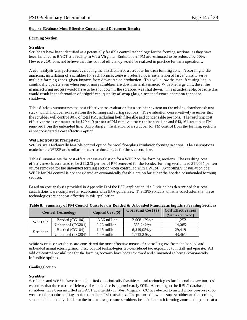
PSD Preliminary Determination Page 14 of 38 Step 4: Evaluate Most Effective Controls and Document Results Forming Section Scrubber Scrubbers have been identified as a potentially feasible control technology for the forming sections, as they have been installed as BACT at a facility in West Virginia. Emissions of PM are estimated to be reduced by 90%. However, OC does not believe that this control efficiency would be realized in practice for their operations. A cost analysis was performed evaluating the installation of a scrubber for each forming zone. According to the applicant, installation of a scrubber for each forming zone is preferred over installation of larger units to serve multiple forming zones, given impacts from downtime on production. This will allow the manufacturing line to continually operate even when one or more scrubbers are down for maintenance. With one large unit, the entire manufacturing process would have to be shut down if the scrubber was shut down. This is undesirable, because this would result in the formation of a significant quantity of scrap glass, since the furnace operation cannot be shutdown. Table 8 below summarizes the cost effectiveness evaluation for a scrubber system on the mixing chamber exhaust stack, which includes exhaust from the forming and curing sections. The evaluation conservatively assumes that the scrubber will control 90% of total PM, including both filterable and condensable portions. The resulting cost effectiveness is estimated to be $29,419 per ton of PM removed from the bonded line and $43,461 per ton of PM removed from the unbonded line. Accordingly, installation of a scrubber for PM control from the forming sections is not considered a cost effective option. Wet Electrostatic Precipitator WESPs are a technically feasible control option for wool fiberglass insulation forming sections. The assumptions made for the WESP are similar in nature to those made for the wet scrubber. Table 8 summarizes the cost effectiveness evaluation for a WESP on the forming sections. The resulting cost effectiveness is estimated to be $11,252 per ton of PM removed for the bonded forming section and $14,085 per ton of PM removed for the unbonded forming section when controlled with a WESP. Accordingly, installation of a WESP for PM control is not considered an economically feasible option for either the bonded or unbonded forming section. Based on cost analyses provided in Appendix D of the PSD application, the Division has determined that cost calculations were completed in accordance with EPA guidelines. The EPD concurs with the conclusion that these technologies are not cost-effective in this application. Table 8: Summary of PM Control Costs for the Bonded & Unbonded Manufacturing Line Forming Sections
Control Technology Capital Cost ($) Operating Cost ($) Cost Effectiveness ($/ton removed)
Bonded (CG104) 13.36 million 2,608,139/yr 11,252 Wet ESP Unbonded (CG204) 3.03 million 555,240/yr 14,085
Bonded (CG104) 6.15 million 6,819,054/yr 29,419 Scrubber Unbonded (CG204) 1.49 million 1,713,246/yr 43,461
While WESPs or scrubbers are considered the most effective means of controlling PM from the bonded and unbonded manufacturing lines, these control technologies are considered too expensive to install and operate. All add-on control possibilities for the forming sections have been reviewed and eliminated as being economically infeasible options. Cooling Section Scrubber Scrubbers and WESPs have been identified as technically feasible control technologies for the cooling section. OC estimates that the control efficiency of each device is approximately 90%. According to the RBLC database, scrubbers have been installed as BACT at a facility in West Virginia. OC has elected to install a low pressure drop wet scrubber on the cooling section to reduce PM emissions. The proposed low-pressure scrubber on the cooling section is functionally similar to the in-line low pressure scrubbers installed on each forming zone, and operates at a

PSD Preliminary Determination Page 15 of 38 lower cost than the high-pressure drop scrubbers evaluated as add-on control devices for the forming section exhaust streams. Step 5: Select BACT Forming and Curing Based on the data presented, OC maintains that potentially applicable add-on control technologies are either technically or economically infeasible to reduce PM emissions from the bonded and unbonded forming sections and the curing section of the bonded manufacturing line. OC will install process equipment built to minimize PM emissions, including low pressure drop “scrubbers” and cyclonic separators, on each forming zone to reduce PM emissions. Entries in the RBLC database, presented in Table 5-3 of the PSD application, show that similar operations on other forming sections have been deemed as satisfying BACT requirements. Specifically, CertainTeed’s Kansas City Plant BACT determination relies on a water spray system inherent in the process on the unbonded line and WESPs on two bonded lines. The determinations for Johns Manville Wayne County Indiana plant indicate that “enclosure and water spray” are similar in nature to the proposed OC configuration. OC is proposing a BACT limit on the bonded line mixing chamber of 7.84 lb/ton of glass pulled and 4 lb/ton of glass pulled for the unbonded forming section. The proposed BACT limits ensure compliance with both NSPS Subpart PPP and Georgia Rule (oo). Cooling OC will install a low pressure drop wet scrubber on the cooling section of the fiberglass manufacturing line. The cooling section is subject to NSPS Subpart PPP, which establishes an 11.0 lb/ton glass pulled limit for the entire wool fiberglass manufacturing line (i.e., forming, curing, and cooling) for filterable PM. Exhaust from the cooling section is also subject to the Georgia Rule (oo) limit of 0.04 gr/dscf. OC is proposing a total PM BACT limit on the cooling section of 0.95 lb/ton of glass pulled. The proposed cooling section BACT limit will also ensure compliance with both NSPS Subpart PPP and Georgia Rule (oo). Conclusion – PM Control The EPD has determined that OC’s proposal to use inline scrubbers and tangential cyclones (inherent to the process) on their bonded and unbonded forming sections, as well as a low pressure drop scrubber on their bonded cooling section to minimize PM emissions, constitutes BACT. The BACT emission limit has been established at 7.84 lb/ton from the bonded line mixing chamber (mixing chamber: includes forming and curing), 0.95 lb/ton from the bonded line cooling section and 4 lb/ton from the unbonded line forming section, as proposed by OC. Compliance with the PM limits must be demonstrated through performance testing and monitoring of the associated scrubbers.
Summary – Control Technology Review for PM from Bonded (CG-1) and Unbonded (CG-2) Fiberglass-Manufacturing Lines
To fulfill the PSD permitting requirements for PM, OC conducted a BACT analysis for the bonded (CG-1) and unbonded (CG-2) manufacturing lines. The BACT selections for these lines are summarized in Table 9 below. The emission limits selected are in the range of previous PSD BACT determination levels published in the RBLC database. Table 9: PM BACT Summary for Bonded Forming and Curing (CG104 & CG105), and Cooling (CG106)
sections and the Unbonded Forming Section CG204 Pollutant Control Technology Proposed BACT Limit
PM - Bonded Line Forming & Curing
Sections
Low Pressure Drop Scrubbers & Cyclone Separators (inherent to process)
7.84 lb/ton (from mixing chamber; includes forming and curing)
PM – Bonded Line Cooling Section
Low Pressure Drop Scrubber 0.95 lb/ton
PM - Unbonded Line Forming Section
Low Pressure Drop Scrubbers & Cyclone Separators (inherent to process)
4 lb/ton
PSD Preliminary Determination Page 16 of 38
GLASS MELT FURNACE CG101 and BONDED & UNBONDED FIBERGLASS MANUFACTURING LINES CG-1 & CG-2 – NITROGEN OXIDES
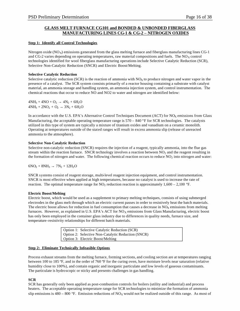
Step 1: Identify all Control Technologies Nitrogen oxide (NOX) emissions generated from the glass melting furnace and fiberglass manufacturing lines CG-1 and CG-2 varies depending on operating temperatures, raw material compositions and fuels. The NOX control technologies identified for wool fiberglass manufacturing operations include Selective Catalytic Reduction (SCR), Selective Non-Catalytic Reduction (SNCR) and Electric Boost/Melting. Selective Catalytic Reduction Selective catalytic reduction (SCR) is the reaction of ammonia with NOX to produce nitrogen and water vapor in the presence of a catalyst. The SCR system consists primarily of a reactor housing containing a substrate with catalyst material, an ammonia storage and handling system, an ammonia injection system, and control instrumentation. The chemical reactions that occur to reduce NO and NO2 to water and nitrogen are identified below: 4NH3 + 4NO + O2 → 4N2 + 6H2O 4NH3 + 2NO2 + O2 → 3N2 + 6H2O In accordance with the U.S. EPA’s Alternative Control Techniques Document (ACT) for NOX emissions from Glass Manufacturing, the acceptable operating temperature range is 570 – 840 °F for SCR technologies. The catalysts utilized in this type of system are typically a mixture of titanium oxides and vanadium on a ceramic monolith. Operating at temperatures outside of the stated ranges will result in excess ammonia slip (release of unreacted ammonia to the atmosphere). Selective Non-Catalytic Reduction Selective non-catalytic reduction (SNCR) requires the injection of a reagent, typically ammonia, into the flue gas stream within the reaction furnace. SNCR technology involves a reaction between NO2 and the reagent resulting in the formation of nitrogen and water. The following chemical reaction occurs to reduce NO2 into nitrogen and water: 6NO2 + 8NH3 → 7N2 + 12H2O SNCR systems consist of reagent storage, multi-level reagent injection equipment, and control instrumentation. SNCR is most effective when applied at high temperatures, because no catalyst is used to increase the rate of reaction. The optimal temperature range for NO2 reduction reaction is approximately 1,600 – 2,100 °F. Electric Boost/Melting Electric boost, which would be used as a supplement to primary melting techniques, consists of using submerged electrodes in the glass melt through which an electric current passes in order to resistively heat the batch materials. The electric boost allows for reduction in fuel consumption that causes a decrease in NOX emissions from melting furnaces. However, as explained in U.S. EPA’s ACT for NOX emissions from Glass Manufacturing, electric boost has only been employed in the container glass industry due to differences in quality needs, furnace size, and temperature-resistivity relationships for different batch materials.
Option 1: Selective Catalytic Reduction (SCR) Option 2: Selective Non-Catalytic Reduction (SNCR) Option 3: Electric Boost/Melting
Step 2: Eliminate Technically Infeasible Options Process exhaust streams from the melting furnace, forming sections, and cooling section are at temperatures ranging between 100 to 185 ºF, and in the order of 760 ºF for the curing oven, have moisture levels near saturation (relative humidity close to 100%), and contain organic and inorganic particulate and low levels of gaseous contaminants. The particulate is hydroscopic or sticky and presents challenges in gas handling. SCR SCR has generally only been applied as post-combustion controls for boilers (utility and industrial) and process heaters. The acceptable operating temperature range for SCR technologies to minimize the formation of ammonia slip emissions is 480 – 800 °F. Emission reductions of NOX would not be realized outside of this range. As most of
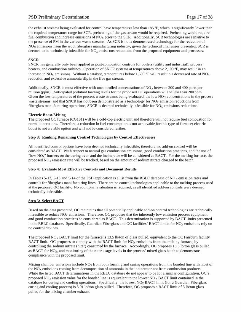
PSD Preliminary Determination Page 17 of 38 the exhaust streams being evaluated for control have temperatures less than 185 ºF, which is significantly lower than the required temperature range for SCR, preheating of the gas stream would be required. Preheating would require fuel combustion and increase emissions of NOX prior to the SCR. Additionally, SCR technologies are sensitive to the presence of PM in the various waste streams. As SCR is not a demonstrated technology for the reduction of NOX emissions from the wool fiberglass manufacturing industry, given the technical challenges presented, SCR is deemed to be technically infeasible for NOX emissions reductions from the proposed equipment and processes. SNCR SNCR has generally only been applied as post-combustion controls for boilers (utility and industrial), process heaters, and combustion turbines. Operation of SNCR systems at temperatures above 2,100 °F, may result in an increase in NOX emissions. Without a catalyst, temperatures below 1,600 °F will result in a decreased rate of NOX reduction and excessive ammonia slip in the flue gas stream. Additionally, SNCR is most effective with uncontrolled concentrations of NOX between 200 and 400 parts per million (ppm). Anticipated pollutant loading levels for the proposed OC operations will be less than 200 ppm. Given the low temperatures of the process waste streams being evaluated, the low NOX concentrations in the process waste streams, and that SNCR has not been demonstrated as a technology for NOX emission reductions from fiberglass manufacturing operations, SNCR is deemed technically infeasible for NOX emissions reductions. Electric Boost/Melting The proposed OC furnace (CG101) will be a cold-top electric unit and therefore will not require fuel combustion for normal operations. Therefore, a reduction in fuel consumption is not achievable for this type of furnace; electric boost is not a viable option and will not be considered further. Step 3: Ranking Remaining Control Technologies by Control Effectiveness All identified control options have been deemed technically infeasible; therefore, no add-on control will be considered as BACT. With respect to natural gas combustion emissions, good combustion practices, and the use of “low NOX” burners on the curing oven and the incinerator will be considered as BACT. For the melting furnace, the proposed NOX emission rate will be tracked, based on the amount of sodium nitrate charged to the batch. Step 4: Evaluate Most Effective Controls and Document Results In Tables 5-12, 5-13 and 5-14 of the PSD application is a list from the RBLC database of NOX emission rates and controls for fiberglass manufacturing lines. There are no control technologies applicable to the melting process used at the proposed OC facility. No additional evaluation is required, as all identified add-on controls were deemed technically infeasible. Step 5: Select BACT Based on the data presented, OC maintains that all potentially applicable add-on control technologies are technically infeasible to reduce NOX emissions. Therefore, OC proposes that the inherently low emission process equipment and good combustion practices be considered as BACT. This determination is supported by BACT limits presented in the RBLC database. Specifically, Guardian Fiberglass and OC facilities’ BACT limits for NOX emissions rely on no control devices. The proposed NOX BACT limit for the furnace is 13.5 lb/ton of glass pulled, equivalent to the OC Fairburn facility RACT limit. OC proposes to comply with the BACT limit for NOX emissions from the melting furnace, by controlling the sodium nitrate (niter) consumed by the furnace. Accordingly, OC proposes 13.5 lb/ton glass pulled as BACT for NOX, and monitoring of the niter usage levels in the process’ mixed glass batch to demonstrate compliance with the proposed limit. Mixing chamber emissions include NOX from both forming and curing operations from the bonded line with most of the NOX emissions coming from decomposition of ammonia in the incinerator not from combustion products. While the listed BACT determinations in the RBLC database do not appear to be for a similar configuration, OC’s proposed NOX emission value for the bonded line is equivalent to the lowest NOX BACT limit contained in the database for curing and cooling operations. Specifically, the lowest NOX BACT limit (for a Guardian Fiberglass curing and cooling process) is 3.01 lb/ton glass pulled. Therefore, OC proposes a BACT limit of 3 lb/ton glass pulled for the mixing chamber exhaust.

PSD Preliminary Determination Page 18 of 38 With respect to the unbonded forming section, NOX emissions are the result of natural gas combustion and impurities in the molten glass. It has been already noted that the possible add-on control devices are most effective when uncontrolled concentrations of NOX are between 200 - 400 parts per million (ppm) and 480 ºF or greater. Anticipated pollutant loading levels for the unbonded forming line will be less than 200 ppm. Also, because the exhaust streams from the unbonded forming line will be less than 185 ºF, which is significantly lower than the required temperature range for the control devices considered, preheating of the gas stream would be required. Given these technical problems, inherent process equipment and good combustion practices are proposed as BACT, with a limit of 0.8 lb/ton glass pulled. Conclusion – NO X Control The EPD has determined that OC’s proposal to use (1) inherent low- NOX process equipment, (2) good combustion control practices, (3) “low NOX” burners in the curing oven and the incinerator (to minimize NOX emissions), and (4) a low nitrogen content batch constitutes BACT. Since the NOX emission rate from the furnace is assumed to be equivalent to the amount of sodium nitrate consumed, multiplied by the conversion factor of 0.543, compliance with furnace NOX limit is required to be demonstrated by monitoring the niter content of the raw materials in the glass batch. It is not believed that monitoring of the forming lines is necessary because the emissions of NOX will be from open flames, with natural gas as fuel. Natural gas does not have much fuel NOX and the temperature of the flames should be low enough that lit tle thermal NOX will be generated. It is not believed that monitoring of the curing oven will be necessary, because the oven will be kept at a relatively low temperature so as not to destroy the bonded fiberglass. Once again, the fuel nitrogen will be negligible and thermal NOX generation should be low. Monitoring the incinerator is also unnecessary because the fuel nitrogen will be also negligible and most of the NOX emissions will come from the decomposition of ammonia, not from the combustion products. The ability of these processes to operate in compliance with their NOX limits must be verified by initial NOX testing.
Summary – Control Technology Review for NO X from Glass Melt Furnace CG101 and Bonded &
Unbonded Manufacturing Lines CG-1 & CG-2 To fulfill the PSD permitting requirements for NOX, OC conducted a BACT analysis for the Furnace CG101 and Manufacturing Lines (CG-1 & CG-2). The BACT selections for these processes are summarized in Table 10. The emission limit selected is representative of previous PSD BACT determination levels published in the RBLC database. Table 10: NOX BACT Summary for Furnace CG101 and Glass Manufacturing Lines CG-1 & CG-2
Pollutant Control Technology Proposed BACT Limit NOX - Furnace Limit Niter in Batch 13.5 lb/ton glass pulled
NOX - Bonded Line Forming & Curing
Good Combustion Control Practices 3.0 lb/ton glass pulled, Mixing Chamber
NOX - Unbonded Line Good Combustion Control Practices 0.8 lb/ton glass pulled
GLASS MELT FURNACE CG101, FORMING CG104, CURING CG105 and
MANUFACTURING LINE CG-2 – CARBON MONOXIDE Step 1: Identify all Control Technologies Carbon monoxide (CO) emissions are generated from the glass melting furnace (CG101), the mixing chamber exhaust, which includes the commingled exhaust from forming and curing (CG104 & CG105), and the unbonded forming section (CG-2). Electric furnaces have low emission rates stemming from the lack of combustion byproducts and the lower temperature of the melt surface caused by bottom heating. CO emissions result from impurities in the molten glass, the combustion of natural gas in forming fiberizers, curing oven burners, and the curing incinerator, as well as from incomplete combustion of organics in the incinerator control device. The CO control technologies identified for wool fiberglass manufacturing operations include baghouse (fabric filter), and the use of good combustion practices (assuring sufficient air-to-fuel ratios). Generally, for combustion equipment, the use of good combustion practices becomes the established BACT work-practice for CO. For non-combustion sources, such as the melting furnace, the only add-on control option identified is the use of a baghouse (fabric filter) for possible emissions reductions. As previously described, baghouses are

PSD Preliminary Determination Page 19 of 38 generally a candidate for PM emissions reductions. However, they can provide limited control for CO emissions. The effectiveness of a baghouse with respect to CO emissions is attributable to both condensation on filterable PM and chemical reaction with PM trapped on the filters. Reported fabric filter efficiencies on regenerative and recuperative wool furnaces are only 30% for CO emissions. The RBLC database was reviewed to determine established BACT limits for other glass melting furnace and forming manufacturing operations. Tables 5-15, 5-16, and 5-17 in the PSD application provide a listing of the recent RBLC determinations for CO with respect to furnaces, forming, and curing, respectively. An RTO is BACT for CO for the curing and cooling sections at the Guardian Fiberglass Inwood, West Virginia facility, but that was determined BACT for VOC control on the line.
Option 1: Combustion controls Option 2: Baghouse (fabric filter)
Step 2: Eliminate Technically Infeasible Options As discussed in step 2 of the PM analysis, baghouses are not technically feasible control options for OC’s furnace operation or forming sections due to the moisture of the exhaust stream and the hydroscopic, sticky characteristic of the PM emissions. Accordingly, the baghouse will not be considered further in this analysis. The exhaust stream from the curing oven will be routed to an incinerator for reduction of VOC emissions. Natural gas will be combusted in the incinerator, resulting in formation of combustion byproducts, including CO. Good combustion practices, including sufficient excess air and maintaining an appropriate temperature for destruction of VOC in the thermal oxidizer, is deemed sufficient for minimizing CO emissions. Step 3: Ranking Remaining Control Technologies by Control Effectiveness For the melting furnace, mixing chamber, and unbonded forming section, no add-on controls are feasible; therefore, no add-on control will be considered as BACT. With respect to emissions from natural gas combustion operations, good combustion practices will be considered as BACT. Table 11: Ranking of CO Control Technology
Control Technology Ranking Control Technology Control Efficiency 1 Good Combustion Control Practices up to 25%
Step 4: Evaluate Most Effective Controls and Document Results In Tables 5-15, 5-16 and 5-17 of the PSD application is a list from the RBLC database of CO emission rates and controls for fiberglass manufacturing lines. No additional evaluation is required, as all identified control devices were deemed technically infeasible. Step 5: Select BACT Based on the data presented, OC maintains that potentially applicable add-on control technologies are technically infeasible for reducing CO emissions. Therefore, OC proposes that the inherently low CO generating process equipment and good combustion practices be determined as BACT. This determination is supported by BACT limits presented in the RBLC database. Specifically, Guardian Fiberglass and Johns Manville facilities’ BACT limits for CO emissions rely on no control devices. The estimated CO emissions from the proposed glass melting furnace are less than 0.5 lb/ton glass pulled. This is lower than the lowest value presented in the RBLC database, 0.728 lb/ton glass pulled for the Guardian Fiberglass facility. OC proposes 0.5 lb/ton glass pulled as BACT for CO. Mixing chamber emissions include CO from both bonded forming and curing operations and are presently estimated to be 5.0 lb/ton glass pulled. While the listed BACT determinations in the clearinghouse do not appear to be for a similar configuration, OC’s proposed CO emission limit is the same as the second lowest CO BACT value for forming operations. Specifically, the lowest CO BACT limit for a Guardian Fiberglass forming and collection process is 4.59 lb/ton glass pulled. OC proposes a BACT limit of 5.0 lb/ton glass pulled for the mixing chamber exhaust. CO emissions from the unbonded forming section are presently estimated to be below 2.4 lb/ton glass
PSD Preliminary Determination Page 20 of 38 pulled. This is below the lowest CO BACT limit contained in the database for the unbonded forming section. Specifically, the lowest CO BACT limit is for a Johns Manville unbonded forming chamber and is 5.83 lb/ton glass pulled. OC proposes a BACT limit of 2.4 lb/ton glass pulled for the unbonded forming section exhaust. Conclusion – CO Control The EPD has determined that OC’s proposal to use only combustion controls to minimize CO emissions constitutes BACT. Compliance with the CO limit must be demonstrated through monitoring work practices and initial performance tests. Outside of monitoring work practices for good combustion, there is little that can be done to control CO emissions from the furnace, the manufacturing lines or the incinerator. Performance tests mu st be done to verify that the CO BACT limits are achieved under normal operating conditions. Unless these tests show unexpectedly high levels of CO, additional monitoring will not be necessary.
Summary – Control Technology Review for CO from Furnace CG101, Forming CG104, Curing CG105, and Unbonded Manufacturing Line CG-2
To fulfill the PSD permitting requirements for CO, OC conducted a BACT analysis for the glass melt furnace, and the bonded and unbonded fiberglass manufacturing lines. The BACT selection is summarized in Table 12. The emission limits selected are representative of previous PSD BACT determination levels published in the RBLC database. Table 12: CO BACT Summary for Furnace CG101, Forming CG104, Curing CG105 and Unbonded
Manufacturing Line CG-2 Pollutant Control Technology Proposed BACT Limit
CO - Furnace Good Combustion Control Practices 0.5 lb/ton CO - Bonded Line Forming & Curing
Good Combustion Control Practices 5.0 lb/ton glass pulled, Mixing Chamber
CO - Unbonded Line Forming Section
Good Combustion Control Practices 2.4 lb/ton
FURNACE CG101 and MANUFACTURING LINES CG-1 & CG-2 – VOLATILE ORGANIC COMPOUNDS
Step 1: Identify all Control Technologies Volatile organic compounds (VOC) emissions generated from the glass melting furnace and fiberglass manufacturing lines CG-1 and CG-2 (forming, curing and cooling) are a result of incomplete combustion, evaporation of binder components, VOC emissions from the "alcohol carriers" of silane which is the active ingredient used in fiberglass coupling, VOCs (light ends) released from high flash point process oil, and ingredient impurities. VOC emissions are primarily ethanol, formaldehyde, methanol, phenol, and combustion byproduct emissions. [Note: Silane is an ingredient of the liquid that is sprayed onto unbonded fiberglass. It is mixed with “alcohol carriers”, so alcohol is driven off and emitted during the fiberglass coupling process in the unbonded line.] The currently available VOC controls include thermal oxidation (regenerative, recuperative, catalytic, and straight thermal units), boiler/process heater, adsorption, scrubbing, absorption, condensation, biodegradation, and flaring. Thermal Oxidation Thermal Oxidation is an effective VOC control technique. VOC can be oxidized to carbon dioxide (CO2) and water vapor (H2O) at a high temperature (generally at least 300 ºF higher than the auto-ignition temperature of an organic compound) with a residence time of 0.5 - 1 seconds. There are four main types of thermal oxidizers. The first is a regenerative thermal oxidizer (RTO), which uses a medium to recover the heat and increase turbulence in the unit; the second is a recuperative oxidizer, which recovers the heat by using the combusted exhaust gas to preheat the inlet air in a heat exchanger; the third is a catalytic oxidizer, which will be explained below; and the last is a straight thermal unit, which does not include heat recovery capabilities, resulting in significantly higher fuel costs, especially for high-volume low-VOC air streams. Catalytic Oxidation Similar to a thermal oxidizer (TO), a catalytic oxidizer oxidizes VOC to CO2 and H2O. However, a catalytic oxidizer uses catalysts to lower the energy levels required for oxidation so that the oxidation can be accomplished at
PSD Preliminary Determination Page 21 of 38 a lower temperature than a TO. As a result, the necessity for auxiliary fuel will be lower than that for a TO, but catalyst costs can be substantial. Catalytic oxidation technology can be utilized with any incineration technology, including regenerative technologies, such as an RTO. Boiler/Process Heater Boilers can be used as control devices for emission streams containing VOC. Many industries use on-site boilers or process heaters as alternatives to installation of thermal incinerators when the contaminant stream has a sufficient heating value or the flow rate of the stream is small relative to the flow rate of the fuel/air mixture. However, as the proposed facility does not have a need for large amounts of steam, hot oil, or any other high temperature fluid, installation of a boiler for manufacturing operations is not warranted. Accordingly, use of a boiler or process heater is not an available control option for consideration at this facility. Adsorption The core component of an adsorption system is a bed of adsorbent media such as activated carbon, resins, or zeolites. The VOC laden gases pass through the media bed, and the VOC is adsorbed on the media as a result of physio-chemical intermolecular attraction between the adsorbent and the contaminant molecules. The cleaned gas is discharged to the atmosphere. As the adsorption process continues, the rate of adsorption declines until the entire media bed is saturated with contaminant and is no longer effective. At this point, the spent media mu st be regenerated either on-site at a regeneration facility or off-site by the media supplier. Using steam to displace adsorbed organic compounds at high temperatures is generally used to regenerate the spent media. Due to the need for media regeneration, dual adsorbent beds are normally utilized for operational flexibility (i.e., one bed acting as the adsorbent bed while the other bed is being regenerated). Adsorption systems are advantageous when the emission stream contains a chemical that may be reused due to its value or availability. If the collected contaminant does not have commercial value, significant waste disposal costs must be included in the cost of operation. Scrubbing Certain VOCs can be removed from a gas stream by using an appropriate scrubbing liquid. Mass transfer of VOC occurs when the scrubbing liquid and the contaminated gas stream contact each other. VOC transfer is achieved by a combination of diffusion, physical absorption, and/or chemical reaction into the scrubbing liquid so the VOCs are removed from the gas stream. There are several different types of scrubbers including packed beds, plate or tray towers, spray chambers, and venturi scrubbers. Condensation Condensation is a simple vapor-liquid equilibrium process that utilizes reduced temperatures and/or high pressures to separate VOC from exhaust streams. When condensers are used for air pollution control, the units usually operate at the pressure of the emission stream. The emission stream is cooled to the saturation point of the condensable material. Once saturated, the liquid can be recovered. The amount of material condensed from a gas stream is limited by the inlet emission stream’s properties (vapor pressure, heat capacity, and temperature) and the characteristics of the condenser. Biodegradation Biodegradation of organic compounds is caused by microbial action. For example, biofiltration systems employ the process of adsorption, absorption, and microbial degradation to remove VOCs from waste gas streams. As the emission stream passes through the biofilter, VOCs are adsorbed onto particles of organic material, absorbed into water droplets within the filter; and then oxidized by microbes. The biofilter is a packed bed bioreactor where the microorganisms are supported on an immobile support. The stationary packing supports the microorganisms and also provides other ingredients such as nitrogen and phosphorus that are necessary for growth of microorganisms. Carbon from the organic pollutants in the emission stream provides the nutrients for growth. Alternatively, organic pollutants may be biodegraded by a “co-metabolic” process where enzymes generated by microorganisms during the digestion of an organic food source also attack the organic pollutant molecule and destroy it. The oxygen required by the microorganisms is derived from the air in the exhaust stream being treated. Pollutant characteristics (biodegradation kinetics, solubility, concentrations) and air emission stream characteristics (temperature, humidity, flow variation) are key factors for the effectiveness of a biodegradation process. Generally, for satisfactory performance, pollutant concentrations and air flow rates should be reasonably constant, as sudden changes can be detrimental to the microbial population.

PSD Preliminary Determination Page 22 of 38 Flare Flares are essentially low efficiency incineration devices and are most appropriate for disposal of waste gases during process start-up, shutdown, and emergencies. This type of control system is a safety device that is used to destroy waste emission streams. Types of flares include steam-assisted (large volumes), air-assisted, and pressure head flares, typically used in series of up to 100 flares, depending on the flow.
Option 1: Thermal oxidation Option 2: Thermal oxidation with a catalyst Option 3: Boiler/Process heater Option 4: Adsorption Option 5: Scrubbing (absorption) Option 6: Condensation Option 7: Biofiltration Option 8: Flare
Step 2: Eliminate Technically Infeasible Options Thermal incineration is a viable option for the curing zone since the exhaust has an approximate exit VOC concentration of 200 ppm. OC proposes the installation of an incinerator on the curing oven exhaust. Based on vendor guarantees, OC expects a 90% reduction or an outlet concentration of 20 ppm of VOC. [Typical VOC outlet concentration guarantees for an incinerator device are 20 ppm or 98% reduction if the inlet concentration is high enough. Therefore, incineration is not technically feasible for controlling streams with concentrations less than 20 ppm, which include a majority of the exhaust streams at the proposed facility (furnace, forming, cooling and raw material handling system).] Catalytic oxidation is deemed technically infeasible since there is a high likelihood of catalyst poisoning from the polymerizing materials (hydrocarbons from the binder) emitted from the fiberglass manufacturing operation and exhaust VOC concentrations from the furnace, forming, cooling and raw material handling system are less than 100 ppm, which is less than the required concentration for efficient catalytic oxidation. Boilers and process heaters are deemed technically infeasible since their installation for manufacturing operations is not warranted at this plant. Adsorption is subject to fouling because of sticky particulates present in the exhaust streams. Additionally, the process streams are high in humidity, so that water would condense on the activated carbon, drastically reducing the efficiency of the absorbent. Finally, the concentrations for most of the exhaust streams are anticipated to be less than 20 ppm, which is too low for adsorbents to be effective. Given the nature of the various waste streams being considered, adsorption is not a technically feasible control option for reduction of VOC emissions. Scrubbers are deemed by the applicant to be technically infeasible for the fiberglass manufacturing operation since scrubbing would require an extreme volume of scrubbing liquid and a prohibitively large scrubber tower due to the low concentration of VOCs in a majority of the streams being evaluated. While it is arguable that a scrubber is feasible but too expensive, it is clear from the RBLC that scrubbers are not used for this type of operation. While the curing exhaust stream has a higher concentration of VOC than other exhaust streams, the temperature of the exhaust stream is so high that it precludes use of a scrubber for VOC control. Generally, the optimal maximum temperature for gaseous absorption is 100 ºF. Therefore, scrubbers are eliminated as a technically feasible control option for VOC emissions from fiberglass manufacturing operations. Condensation is deemed by the applicant to be technically infeasible for the fiberglass manufacturing operation since low VOC concentrations, less than 20 ppm, in most of the exhaust streams will result in low removal efficiencies and an excessive use of energy if using condensation to remove VOCs. Additionally, the condensation surface would likely experience substantial fouling given the presence of sticky particulate in the exhaust streams from any of the manufacturing zones. Therefore, condensation is eliminated as a technically feasible control option for emissions associated with fiberglass manufacturing operations. Biodegradation is deemed technically infeasible for the curing process since the exhaust stream temperature is in excess of 300 ºF and cannot be reduced efficiently to temperatures ranging from 60 to 105 ºF. Therefore, the high curing temperatures would kill the biomass. The PM characteristics of the glass melt furnace, forming and cooling exhaust streams, would clog the biofilter beds, rendering them inoperative in a short amount of time. Therefore, a

PSD Preliminary Determination Page 23 of 38 particulate removal system upstream of the biofilter would be necessary. However, since all add-on control devices for PM emissions were deemed either technically or economically infeasible, a biodegradation unit will also be technically infeasible for these streams. Flares achieve high control efficiency as long as the heat content of the incoming waste stream exceeds 300 Btu/scf. In the case of low organic concentration gas streams, supplemental fuel costs generally eliminate flares as a viable control alternative. For the waste streams being considered, the total heat content is less than 1.0 Btu/scf; therefore, flares are considered technically infeasible control options. Step 3: Ranking Remaining Control Technologies by Control Effectiveness For the glass melt furnace and the forming and cooling sections, no-add on controls remain feasible; therefore, no add-on control will be considered as BACT. With respect to natural gas combustion emissions, good combustion practices will be considered as BACT. For the curing process, the only technically feasible control option identified is thermal oxidation for VOC emissions reduction. Table 13: Ranking of VOC Control Technology
Control Technology Ranking Control Technology Control Efficiency 1 Thermal oxidation ~50-75%
Step 4: Evaluate Most Effective Controls and Document Results All identified controls devices were deemed technically infeasible for the glass melt furnace, the forming and cooling sections. The only control technology considered for the curing section is thermal oxidation. OC proposes to install an incinerator on the curing section as BACT. Step 5: Select BACT OC maintains that potentially applicable add-on control technologies are technically infeasible to reduce VOC emissions from the melting furnace, forming sections, and cooling process; however, add-on controls are feasible for the curing section. OC proposes that (1) process equipment with inherently low emissions, (2) good combustion practices and (3) minimizing the use of silane and binder process oil are BACT for the melting furnace, forming sections, and cooling process. [Note: Since silane and binder process oil are relatively expensive ingredients of OC’s binder system, it is in their interest to limit the use of these compounds and thus minimize the emissions of the "alcohol carrie rs" and process oil. EPD therefore does not believe that monitoring silane and binder process oil usage is necessary to assure that VOC emissions are minimized.] These BACT determinations are supported by BACT limits presented in the RBLC database, which are summarized in Tables 5-18, 5-19, and 5-20 of the PSD application. Specifically, the Guardian Fiberglass and Johns Manville facilities’ melting furnace and forming sections BACT limits for VOC emissions rely on no control devices. In addition, the Gu ardian Fiberglass facility curing and cooling line BACT limits for VOC emissions rely on thermal oxidation. VOC emissions from the proposed glass melting furnace are estimated to be less than 0.38 lb/ton glass pulled, equivalent to the only BACT determination contained in the RBLC database for an electric melt furnace. OC is proposing this value as the VOC BACT limit for the proposed glass melting furnace (CG101). OC is proposing to install an incinerator on the exhaust of the curing process. [The incinerated exhaust is then to be ducted into a mixing chamber where it is commingled with the exhaust stream from bonded forming, before being exhausted into the atmosphere.] With this configuration, the estimated worst-case potential emissions from the mixing chamber are 4 lb/ton of glass pulled. OC proposes a limit of 4 lb/ton of glass pulled as BACT for controlled VOC emissions from the mixing chamber exhaust (which is the combined exhaust from the forming and curing sections. Estimated emissions from the cooling section (CG106) are less than 0.2 lb/ton of glass pulled. OC proposes a limit of 0.2 lb/ton of glass pulled as BACT for the cooling process. OC proposes a BACT limit of 2.37 lb/ton glass pulled for the unbonded forming section (CG204). Minimizing the use of silane will help control the VOC emissions from the unbonded line since it is the primary contributor of VOC (0.63 lb ethanol/lb silane). As mentioned above silane contributes to the economic cost of the final product and will be in OC’s best interest to control the quantity used.
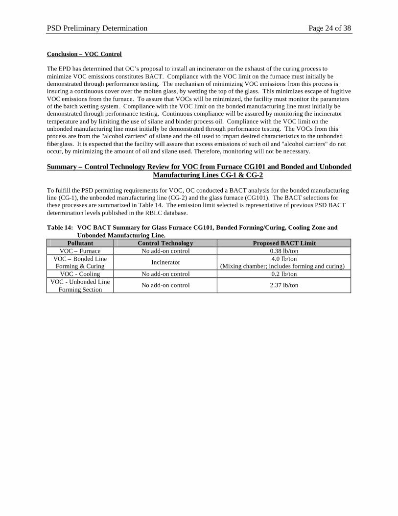
PSD Preliminary Determination Page 24 of 38 Conclusion – VOC Control The EPD has determined that OC’s proposal to install an incinerator on the exhaust of the curing process to minimize VOC emissions constitutes BACT. Compliance with the VOC limit on the furnace must initially be demonstrated through performance testing. The mechanism of minimizing VOC emissions from this process is insuring a continuous cover over the molten glass, by wetting the top of the glass. This minimizes escape of fugitive VOC emissions from the furnace. To assure that VOCs will be minimized, the facility must monitor the parameters of the batch wetting system. Compliance with the VOC limit on the bonded manufacturing line must initially be demonstrated through performance testing. Continuous compliance will be assured by monitoring the incinerator temperature and by limiting the use of silane and binder process oil. Compliance with the VOC limit on the unbonded manufacturing line must initially be demonstrated through performance testing. The VOCs from this process are from the "alcohol carriers" of silane and the oil used to impart desired characteristics to the unbonded fiberglass. It is expected that the facility will assure that excess emissions of such oil and "alcohol carriers" do not occur, by minimizing the amount of oil and silane used. Therefore, monitoring will not be necessary. Summary – Control Technology Review for VOC from Furnace CG101 and Bonded and Unbonded
Manufacturing Lines CG-1 & CG-2 To fulfill the PSD permitting requirements for VOC, OC conducted a BACT analysis for the bonded manufacturing line (CG-1), the unbonded manufacturing line (CG-2) and the glass furnace (CG101). The BACT selections for these processes are summarized in Table 14. The emission limit selected is representative of previous PSD BACT determination levels published in the RBLC database. Table 14: VOC BACT Summary for Glass Furnace CG101, Bonded Forming/Curing, Cooling Zone and
Unbonded Manufacturing Line. Pollutant Control Technology Proposed BACT Limit
VOC – Furnace No add-on control 0.38 lb/ton VOC – Bonded Line Forming & Curing
Incinerator 4.0 lb/ton (Mixing chamber; includes forming and curing)
VOC - Cooling No add-on control 0.2 lb/ton VOC - Unbonded Line
Forming Section No add-on control 2.37 lb/ton
PSD Preliminary Determination Page 25 of 38
5.0 TESTING AND MONITORING REQUIREMENTS Raw Material Handling: Testing Requirements The Permittee is required to test the raw material handling baghouse exhaust for PM to demonstrate compliance with the BACT limit. Testing is required within 180 days of startup of the raw material handling operations. There is only one stack venting a number of exhausts, so it is this stack RM100 that will be tested. Monitoring Requirements The Permittee is required to perform daily visible emission checks from the raw material handling stack RM100 as the primary monitoring tool. The Permittee is required to inspect each baghouse for proper operation on a weekly basis as a secondary monitoring tool to assure compliance with the PM limitations. CAM Applicability: These operations are not required to meet the requirements of the CAM plan. See Section 3.0 of this document for a discussion of CAM requirements. Glass Melting Furnace CG101: Testing Requirements Glass Melting Furnace CG101 is required by 40 CFR Part 63, Subpart NNN to conduct initial performance testing, within 180 days of startup, for PM (EPA Method 5). The tests are will be done to determine compliance with limits under PSD and 40 CFR Part 63 Subpart NNN. Monitoring Requirements The Permittee is required to monitor continuous glass pull rate and record this data on an hourly basis in accordance with 40 CFR Part 63 Subpart NNN. Data from the water flow rate to the batch wetting system must be recorded four times per day, with at least five hours between each recording. CAM Applicability The unit is a large PSEU for NOX and is required to meet the requirements for a CAM plan when the Title V application is submitted. See Section 3.0 of this document for a discussion of CAM requirements. Manufacturing Line CG-1: Testing Requirements For the forming, curing and cooling of Manufacturing Line CG-1 (bonded) the Permittee is required by this permit to conduct initial performance tests within 180 days of startup for PM (EPA Method 5E), NOX (EPA Method 7E), CO (EPA Method 10), VOCs (EPA Method 18) and formaldehyde (EPA Method 316 or 318) to demonstrate compliance with the BACT limitations. This emission source is required by 40 CFR Part 63 Subpart NNN to have performance testing for formaldehyde within 180 days of startup. This emission source is required by Part 60 Subpart PPP to have performance testing for PM “Within 60 days after achieving the maximum production rate at which the affected facility will be operated, but not later than 180 days after initial startup of such facility.” Monitoring Requirements The Permittee is required to monitor and record the free-formaldehyde content of each resin shipment received and used in the formulation of binder, in accordance with 40 CFR Part 63 Subpart NNN. The Permittee is required to monitor and record the formulation of each binder used, in accordance with 40 CFR Part 63 Subpart NNN. The Permittee is required to monitor and record the product LOI and product density of each bonded wool fiberglass product, in accordance with 40 CFR Part 63 Subpart NNN. The Permittee is required to monitor and record the liquid flow rate and pressure drop across the low pressure scrubbers from the forming section, as well as the low pressure scrubber in the cooling section, in accordance with 40 CFR Part 60 Subpart PPP.

PSD Preliminary Determination Page 26 of 38 The Permittee is required to monitor and record the line speed, trimmed mat width, and mat gram weight, in accordance with 40 CFR Part 60 Subpart PPP. CAM Applicability The unit is a large PSEU and will be required to meet the requirements for a CAM plan for PM, CO and VOC. See Section 3.0 of the Preliminary Determination for a discussion of CAM requirements. Manufacturing Line CG-2: Testing Requirements Manufacturing Line CG-2 is required by this permit to conduct initial performance tests within 180 days of startup for PM (EPA Method 5E), NOX (EPA Method 7E), VOCs (EPA Method 18), CO (EPA Method 10), and formaldehyde (EPA Method 316 or 318) to demonstrate compliance with the BACT limitations. This emission source is required by Part 60 Subpart PPP to conduct performance testing for PM within 180 days of startup. Monitoring Requirements The Permittee is required to monitor and record the liquid flow rate and pressure drop across the low pressure scrubbers from the forming section, in accordance with 40 CFR Part 60 Subpart PPP. The Permittee is required to monitor and record the line speed, trimmed mat width, and mat gram weight in accordance with 40 CFR Part 60 Subpart PPP. CAM Applicability This unit is not a large PSEU, so these operations are not required to meet the requirements for a CAM plan. See Section 3.0 of this document for a discussion of CAM requirements.

PSD Preliminary Determination Page 27 of 38
6.0 AMBIENT AIR QUALITY REVIEW
An air quality analysis is required to determine the ambient impacts associated with the proposed wool fiberglass insulation manufacturing facility in Cordele, Georgia. The purpose of the air quality analysis is to demonstrate that emission increases or decreases from the proposed project will not cause or contribute to a violation of any applicable National Ambient Air Quality Standard (NAAQS) or PSD increment in a Class I or Class II area. This analysis is required for each pollutant emitted in an amount over the PSD significant emission rate (SER) threshold. As shown in Table 1 of this document, the net emissions increase from this project exceeds the PSD SER for PM/PM10, NOX, CO, and VOC. Therefore, Owens Corning performed an ambient air quality analysis for these pollutants. Compliance with any NAAQS or PSD increment is based on the modeled ambient impact caused by the applicant’s proposed emissions as well as those sources surrounding the plants within the impact area. Monitoring: EPD does not maintain ambient air monitors for PM/PM10, CO, and ozone (VOC) in Crisp County in the vicinity of the Cordele fiberglass plant being constructed. However, EPD maintains state and local ambient monitors (SLAM) for PM/PM10, NOX, CO, and VOC throughout the state of Georgia. The ambient air quality in Crisp County can be adequately estimated by using background concentrations for similar areas in Georgia. The existing network of Georgia monitoring has been determined to be able to provide representative data that may be used in place of pre-construction monitoring by the company. The EPD has determined that an appropriate background level for NO2 on an annual averaging period is 27 ug/m3. This value is based on data observed at the Conyers Monastery in Rockdale County, during 1996 - 2000. Using information from a number of monitoring stations in Georgia, EPD also has determined that the appropriate background values for PM10 are 38 ug/m3 and 20 ug/m3, for 24-hour and annual averaging periods, respectively. The impacts quantified in the Significance Analysis for PM, NO2 and CO, added to the background levels, were compared with the de minimis concentrations to determine if ambient monitoring requirements need to be considered as part of this permit action. Although the maximum modeled impacts in the PM and NO2 significance analyses exceed the monitoring deminimis levels, OC requested that the EPD waive the pre-construction monitoring requirements because ambient monitoring data are already available from the Georgia EPD’s monitoring stations located in Georgia. Modeling: In general, the EPD assesses the ambient impact of a source through the use of mathematical dispersion models. The models are based on the assumption that the dispersion of pollutants is primarily a function of wind speed and direction, atmospheric stability conditions, and the characteristics of the effective point discharge of the exhaust plume. To predict ambient air concentrations, the models simulate the plume exhausting from the stack, rising a certain distance into the atmosphere, leveling off, and continuing downwind over relatively flat terrain. The concentrations of the pollutants are assumed to have a Gaussian distribution about the downwind axis centerline of the plume. In analyzing the air quality impact of these modifications, Owens Corning used the EPA Industrial Source Complex Short-Term Version 3 (ISCST3) model for all PSD modeling results presented in the preliminary determination except the Class I analyses. ISCST3 is a Gaussian plume dispersion model that estimates hour-by-hour ground-level concentrations caused by emissions from an elevated source. The model provides maximum 1-hour, 8-hour, 24-hour, and annual average concentrations for receptors located on many grid types around the source at various downwind distances. The model also takes into account the effect of downwash caused by nearby buildings and structures. For the air quality analyses, National Weather Service (NWS) meteorological data from the years 1974-1978 for Macon, Georgia, were used as surface data and the same years for Centreville, Alabama, were used as upper air data. For the NAAQS and PSD Increment modeling analyses, the direction-specific building dimensions used as input to the ISCST3 model were calculated using the BREEZE®-AIR software, which incorporates the EPA’s Building Profile Input Program (BPIP) to calculate flow vectors based on 36 possible wind directions in order to allow for building downwash. The modeling included all stacks with emission changes resulting from the new facility.

PSD Preliminary Determination Page 28 of 38 Increment Consumption: The PSD regulations establish specific maximum allowable increases in ambient concentrations (or increments) for PM10, NOX, SO2, CO and other pollutants for all areas in compliance with the NAAQS. All areas of the country are categorized as a function of overall use. The regulations were designed to prevent significant air quality deterioration by specifying allowable incremental changes in PM10, NOX, and SO2 concentrations within each area category. The area categories are defined below:
Class I – Those areas where almost any deterioration of current air quality is undesirable, and little or no industrial development would be allowed (e.g., national parks, wilderness areas). Class II – Those areas where moderate, well-controlled energy or industrial growth is desired without air quality deterioration up to the national standards (all attainment areas not categorized as Class I were initially designated Class II). Class III – Those areas where substantial energy or industrial development is intended, and where modest increases in ambient concentrations above Class II increments, but below national standards, would be allowed (designation to Class III must follow strict redesignation procedures).
The Crisp County area, and all other attainment areas in Georgia not designated as Class I areas, are Class II areas. The Class I areas near the proposed OC facility are St. Mark Wilderness Area, Okefenokee National Wildlife Refuge Area and Bradwell Bay Wilderness Area. The first step in the air quality analysis was to determine whether the net emissions increases (i.e., facility-wide potential emissions for a green field facility) associated with the proposed OC Cordele facility, when processed in a dispersion model, cause a significant impact upon the area surrounding a facility. “Significant” impacts are defined by ambient concentration thresholds commonly referred to as the Modeling Significance Levels (MSL). This “significance analysis” determined whether the proposed OC plant could forgo a full-scale impact analysis to demonstrate compliance with the NAAQS and PSD Class II Increments. The results of the significance analysis conducted for the Owens Corning proposed plant are summarized in Table 23 below. The impacts due to the total project emissions of NO2, PM10 and CO were calculated in this analysis using the ISCST3 dispersion model. Table 23 shows the highest concentration modeling result for each pollutant. The complete modeling analysis results are located in Section 3 of the Permit Application Class II Air Quality Modeling Analyses. The EPD modeling results are found in Appendix C of this document. Table 23. Class II Modeling Results vs. Significant Impact Levels & Significant Monitoring Concentrations
Pollutant Averaging Period
PSD Significant Impact Level
(ug/m3)
Monitoring Concentration Level (ug/m3)
Modeled Concentration
(ug/m3) Notes
NO2 Annual 1 14 18.30 Additional modeling needed
24-Hour 5 10 29.33 Additional modeling needed PM 10 Annual 1 -- 3.42 Additional modeling needed 1-Hour 2,000 -- 41.13 No further modeling needed CO 8-Hour 500 575 19.77 No further modeling needed
As shown in Table 23, the project’s impact is below the significant impact level (SIL) for both CO averaging periods; therefore, no further modeling is required for this pollutant. The maximum CO concentration is also below its corresponding pre-construction monitoring levels; therefore no monitoring is required for CO. A significant impact analysis was done for the emissions increases of NO2 and PM10. Since concentrations exceed the NAAQS SIL, PSD Increment analyses were carried out for NO2 and PM10. NO2 and PM10 also exceeded the pre-construction monitoring levels. However, as indicated above, state local area monitors (SLAM) for NO2 and PM10 are available and the data from these monitors provide reasonable (or in some cases conservative) estimates of the background pollutant concentrations considered in this analysis; therefore, pre-construction monitoring is not considered necessary for NO2 or PM10.
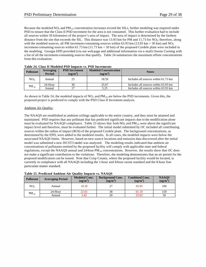
PSD Preliminary Determination Page 29 of 38 Because the modeled NO2 and PM10 concentration increases exceed the SILs, further modeling was required under PSD to ensure that the Class II PSD increment for the area is not consumed. This further evaluation had to include all sources within 50 kilometers of the project’s area of impact. The area of impact is determined by the farthest distance from the site that exceeds the SIL. This distance was 13.93 km for PM and 11.73 for NO2; therefore, along with the modeled sources, all PM increment-consuming sources within 63.93 km (13.93 km + 50 km) and NO2 increment-consuming sources within 61.73 km (11.73 km + 50 km) of the proposed Cordele plant were included in the modeling. Georgia EPD provided (via our web page and additional information via e-mail) Owens Corning with a list of all the increment-consuming sources that qualify. Table 24 summarizes the maximum offsite concentrations from this evaluation: Table 24. Class II Modeled PSD Impacts vs. PSD Increments
Pollutant Averaging Period
PSD Increment (ug/m3)
Modeled Concentration (ug/m3)
Notes
NOX Annual 25 18.59 Includes all sources within 61.73 km
24-Hour 30 25.67 Includes all sources within 63.93 km PM 10 Annual 17 5.25 Includes all sources within 63.93 km As shown in Table 24, the modeled impacts of NO2 and PM10 are below the PSD increments. Given this, the proposed project is predicted to comply with the PSD Class II Increment analysis. Ambient Air Quality: The NAAQS are established as ambient ceilings applicable to the entire country, and they must be attained and maintained. PSD requires that any pollutant that has predicted significant impacts due to the modification alone must be evaluated for NAAQS compliance. Table 23 shows that both NO2 and PM10 were above the significant impact level and therefore, must be evaluated further. The initial model submitted by OC included all contributing sources within the radius of impact (ROI) of the proposed Cordele plant. The background concentrations, as determined by the EPD, were added to the modeled results. In all cases, the modeled impacts were below the associated NAAQS limits. However, based on new source locations and emission data discovered after the initial model was submitted a new ISCST3 model was analyzed. The modeling results indicated that ambient air concentrations of pollutants emitted by the proposed facility will comply with applicable state and federal regulations, except the NAAQS annual and 24-hour PM10 concentrations. However, the results show that OC does not make a significant contribution to the violations. Therefore, the modeling demonstrates that an air permit for the proposed modification can be issued. Note that Crisp County, where the proposed facility would be located, is currently in compliance with all NAAQS including the 1-hour and 8-hour ozone standard and the 8-hour fine particulate matter standard. Table 25. Predicted Ambient Air Quality Impacts vs. NAAQS
Pollutant Averaging Period Modeled Conc. (ug/m3)
Background Conc. (ug/m3)
Combined Conc. (ug/m3)
NAAQS (ug/m3)
NO2 Annual 18.30 27 45.85 100
24-Hour 22.61 38 61.18 150 PM 10 Annual 3.42 20 25.92 50

PSD Preliminary Determination Page 30 of 38 Class I Evaluation: There are no Class I areas within 100 km, but there are some within 200 km of the proposed Cordele facility. The Permittee conducted air quality analyses in support of the PSD permit application to address Class I PSD Increments and Air Quality Related Values (AQRV) at three Class I areas, which include Okefenokee National Wildlife Refuge, Bradwell Bay Wilderness and Saint Marks National Wildlife Refuge. The purpose of the Class I Area Modeling analyses is to demonstrate that the proposed facility will not consume more than the available Class I PSD increments in the Class I Area. A significance analysis was conducted first, to determine whether the project could be expected to have a significant impact in the Class I Area. Table 26 details the findings of the modeling for the three Class I areas for the proposed OC facility. The maximum impacts are well below the significant impact levels for all pollutants and all averaging periods. Accordingly, compliance with the applicable Class I Increments is predicted so an analysis of the cumulative impacts from the proposed facility and regional sources together is not necessary. Table 26. Class I Ambient Air Quality Impacts vs. Significance Levels
Pollutant Averaging Period
Significance Level
(ug/m3)
Okefenokee Maximum Predicted Impact (ug/m3)
St. Marks Maximum Predicted
Impact (ug/m3)
Bradwell Bay Maximum Predicted Impact (ug/m3)
Conclusion
NO2 Annual 0.1 1.77E-03 5.61E-04 4.50E-04 No additional modeling required
24-Hour 0.32 0.136 0.080 0.063 No additional modeling required PM10
Annual 0.16 0.006 0.002 0.002 No additional modeling required
3-Hour 1 0.008 0.006 0.005 No additional modeling required
24-Hour 0.2 0.004 0.002 0.002 No additional modeling required
SO2
Annual 0.08 1.33E-04 4.70E-05 4.22E-05 No additional modeling required
Complex Terrain: Because some of the area surrounding the mill is classified as complex terrain (terrain which has an elevation that is equal to or exceeds the lowest stack height of the sources being modeled), a complex terrain modeling analysis was completed. The complex terrain modeling was based on the EPA Region 4 guidance for complex terrain processing. Analysis was performed to determine whether intermediate and complex terrain is an important factor that must be addressed in the analysis using an alternative complex terrain model (simple terrain option), or whether ISCST3 can be applied using default processing options. The relevant components of the EPA Region 4 guidance for complex terrain processing are found in Section 3 – Intermediate Terrain Analysis. Following the guidance, screen modeling was completed in the default mode for complex terrain that takes the greater of the applicable predictions from the complex and simple terrain algorithms. If the resulting concentrations were below the SIL, no further air quality analysis (modeling to demonstrate compliance with the NAAQS or PSD Increment) would be required. As demonstrated, the impacts from this facility are below the SILs for receptors with elevations greater than the complex terrain elevation of 450 feet in the PM and NO2 significant analysis; however the impacts were found to be above the SILs for PM and NO2 at receptors with elevation greater than the intermediate terrain elevation of 420 feet. Therefore, complex terrain analysis (as opposed to simple terrain which is the ISCST3 default option) is required for PM and NO2. However, further evaluation of the PM and NO2 modeling found that the complex terrain algorithms were the controlling algorithms for the intermediate terrain receptors, and therefore the ISCST3 model may be used in default mode for all receptors. Air Toxics: There are no applicable NAAQS or specific Georgia ambient air standards for the non-criteria pollutants listed in Table 1. Impacts from each of the pollutants listed in Table 6-2 of the permit application Class II air quality modeling analyses were analyzed using the current version (June 21, 1998) of the EPD Guidance for Ambient Impact Assessment of Toxic Air Pollutant Emissions (referred to as the Georgia Air Toxics Guideline). The Georgia A ir Toxics Guideline is a guide for estimating the environmental impact of sources of toxic air pollutants.
PSD Preliminary Determination Page 31 of 38 A toxic air pollutant is defined as any substance that may have an adverse effect on public health, excluding any specific substance that is covered by a State or Federal ambient air quality standard. The EPA SCREEN3 computer screening dispersion model is first used to predict the maximum 15-minute, 24-hour, and annual average ground-level concentration (referred to as Maximum Ground Level Concentration (MGLC)) for each pollutant. Each MGLC is then compared to its respective Acceptable Ambient Concentration (AAC). The basis for calculation of AAC comes from the pollutant toxicity rating systems described in the Georgia Air Toxics Guideline (dated June 1998). If the screening analysis does not demonstrate an acceptable MGLC, the ISCST3 refined dispersion model is used to predict a more accurate MGLC. The SCREEN3 evaluation demonstrated that maximum impacts of toxic air pollutants due to OC’s proposed facility are less than the maximum AAC levels for all compounds except formaldehyde, ammonia, hexavalent chromium, phenol, methanol, arsenic, lead and nickel. As provided by the Georgia Guidelines, ISCST3 modeling was completed for those pollutants that were not screened out through the SCREEN3 program. Based on EPD’s analysis, the predicted MGLC for each applicable pollutant is below its Georgia EPD AAC. Appendix C of this document contains the toxic modeling results. Class I Visibility Analysis: Visibility can be affected by plume impairment or regional haze. Plume impairment results when there is a contrast or color difference between the plume and a viewed background. Plume impairment is generally only of concern when the Class I area is near the proposed source (i.e., less than 50 km). Since the distance between the Cordele facility and the three Class I Areas evaluated ranges between approximately 170 km and 200 km, only regional haze was considered in this analysis. Note that since visibility is not an AQRV for Bradwell Bay, visibility impacts at this area were not considered in this analysis. This approach utilizes the CALPUFF model to determine the change from the specified reference levels for the Class I Areas and compares the change with the prescribed threshold values. Under the Class I Area guidance, if the proposed project results in a percent change in B-extinction, which is always less than 5%, the project can proceed without further analysis. The analysis found a maximum B-extinction for the Okefenokee and Saint Marks areas of 2.9% and 1.3% respectively. The results of the visibility analyses show that at no time do the emissions from the proposed OC facility cause visibility extinction in excess of the 5% threshold. Therefore, no further analysis is necessary. Class II Visibility Analysis: A Class II visibility analysis was evaluated for nearby Class II areas utilizing the VISCREEN model. The nearest Class II area is the Georgia Veterans State Park, which is approximately 10 km to the west of the facility. It is located within the project’s SIA and so must be considered in the visibility analysis. The Crisp County local airport is located within the maximum SIA; however, the airport serves general aviation only. Therefore, this airport is excluded from the VISCREEN analysis, as only regional, national, or international airports require visibility analysis. The primary variables that affect whether a plume is visible or not at a certain location are (1) quantity of emissions, (2) types of emissions, (3) relative location of source and observer, and (4) the background visibility range. For this project, visibility analysis was performed using the latest version of the EPA VISCREEN model according to the guidelines published in the Workbook for Plume Visual Impact Screening and Analysis (EPA- 450/4-88-015). The VISCREEN model is designed specifically to determine whether a plume from a facility may be visible from a given vantage point. VISCREEN performs visibility calculations for two assumed plume-viewing backgrounds (horizon sky and a dark terrain object). The model assumes that the terrain object is perfectly black and located adjacent to the plume on the side of the centerline opposite the observer. The VISCREEN visibility model was set up to model the increase in PM and NOx emissions from the facility based on the worst-case plume dispersion characteristics. A “Level 2” analysis, a less conservative analysis than “Level 1” analysis, was conducted for the Georgia Veterans State Park using the joint frequency distribution of atmospheric stability and wind speeds causing worst-case meteorological conditions during daylight hours when the winds actually blow emissions from the plant to the park. As an additional refinement to the “Level 2” screening analysis, the NO2 emission rate was scaled by 75%, following the Ambient Ratio Method, to account for the conversion of NOx to NO2 in the atmosphere, since the latter is the visibility impairing species. The background ozone concentration input was 27 ppb, representing the three-year average between October 2000 and September 2003 of

PSD Preliminary Determination Page 32 of 38 year-round ozone measurements. The “Level 1” default options were used for all other model inputs. As directed in the Workbook , a background visual range of 25 km was used for the area of middle Georgia where Cordele is located. For views inside the Class II area (Georgia Veterans State Park), Owens Corning performed calculations using the model for the two assumed plume -viewing backgrounds. The VISCREEN model output contains several variables: theta, azi, distance, alpha, critical and actual plume ?E, and critical and actual plume contrast. These variables are defined as follows:
1. Theta – Scattering angle (the angle between direction solar radiation and the line of sight). If the observer is looking directly at the sun, theta equals zero degrees. If the observer is looking away from the sun, theta equals 180 degrees.
2. Azi – The azimuthal angle between the line connecting the observer and the line of sight. 3. Alpha – The vertical angle between the line of sight and the plume centerline. 4. ? E – Used to characterize the perceptibility of a plume on the basis of the color difference between the
plume and a viewing background. A ?E of less than 2.0 signifies that the plume is not perceptible. 5. Contrast – The contrast at a given wavelength of two colored objects such as plume/sky or
plume/terrain. The analysis is generally considered satisfactory if ?E and Contrast are less than the critical values established. These critical values are Class I, not Class II, area thresholds. The EPD has reviewed the VISCREEN results presented in the permit application and determined that the visual impact criteria are met inside the Georgia Veterans State Park. Only results inside the receptor area were considered in this analysis, since results outside the areas corresponding to integral vistas are not protected under Georgia’s SIP for Class II areas.

PSD Preliminary Determination Page 33 of 38
7.0 ADDITIONAL IMPACT ANALYSES The PSD regulations require an analysis of impairment to visibility, soils, and vegetation that will occur as a result a proposed facility and an analysis of the air quality impact projected for the area as a result of the general commercial, residential, and other growth associated with the proposed project. Visibility: Visibility impairment is any perceptible change in visibility (visual range, contrast, atmospheric color, etc.) from that which would have existed under natural conditions. Poor visibility is caused when fine solid or liquid particles, usually in the form of volatile organics, nitrogen oxides, or sulfur o xides, absorb or scatter light. This light scattering or absorption actually reduces the amount of light received from viewed objects and scatters ambient light in the line of sight. This scattered ambient light appears as haze. Another form of visibility impairment in the form of plume blight occurs when particles and light-absorbing gases are confined to a single elevated haze layer or coherent plume. Plume blight, a white, gray, or brown plume clearly visible against a background sky or other dark object, usually can be traced to a single source such as a smoke stack. Owens Corning presented visibility impact analyses in Section 7, the application’s Class II air quality modeling analyses, which were discussed in the previous section of this determination. The results of these analyses showed that the proposed project should have no perceptible impact on visibility within the Class II Area of interest. Soils and Vegetation: No sensitive soil types are known to exist within the significant impact area of the project. Moreover, the areas of maximum impact are generally cultivated or forested and demonstrate no obvious sensitivity to industrial air emissions. Since ground-level concentrations of PM and NOx are not expected to increase by a significant degree as a result of this project, the impacts on soil and vegetation are predicted to be insignificant and no discernible changes are expected to result from the proposed facility. Growth: No adverse impacts on growth are anticipated from the proposed OC Cordele facility since all construction activities will occur for a finite time period and no major increases in housing or commercial growth are expected. OC expects that the majority of the permanent employees of the facility will be current residents of the Crisp County area. The proposed facility is not expected to cause any related industrial or commercial growth that would have an impact on local ambient air quality.

PSD Preliminary Determination Page 34 of 38
8.0 EXPLANATION OF DRAFT PERMIT CONDITIONS The permit requirements for this proposed facility are included in draft Permit No. 3296-081-0063-P-01-0 Table 1 – Source List The EPD has provided a table of the proposed facility emission units in Table 1 of the PSD permit. This includes the glass melt furnace (CG101), the bonded and unbonded fiberglass-manufacturing lines (CG-1 and CG-2), and the raw material handling and product packaging operations (CG100). Part 1. – General Requirements Conditions 1.1 through 1.4 are general template conditions from the SIP permit template. Part 2. – Allowable Emissions Condition 2.1 requires the Permittee to comply with all applicable provisions of 40 CFR 63-National Emission Standards for Hazardous Air Pollutants, Subpart A-General Provisions. Condition 2.2 requires the Permittee to comply with all applicable provisions of 40 CFR 63, Subpart NNN - National Emission Standards for Hazardous Air Pollutants for Wool Fiberglass Manufacturing. Condition 2.3 requires the Permittee to comply with all applicable provisions of 40 CFR 60-New Source Performance Standards, Subpart A-General Provisions. Condition 2.4 requires the Permittee to comply with all applicable provisions of 40 CFR 60, Subpart PPP – Standards of Performance for Wool Fiberglass Insulation Manufacturing Plants. Condition 2.5 requires the Permittee not to discharge into the atmosphere from the rotary spin fiberglass manufacturing line (CG-1) any gases that contain formaldehyde in excess of 0.8 pound per ton of molten glass pulled from the line. This limit satisfies the require ment of 40 CFR 63.1382(a)(2)(ii) for new fiberglass manufacturing lines (bonded lines). Condition 2.6 requires the Permittee not to discharge into the atmosphere from the raw material handling operations (CG100) any gases, which contain particulate matter in excess of 0.01 grain per dry standard cubic foot of exhaust gas. This limit represents the “Best Available Control Technology” (BACT) requirement, determined in accordance with the PSD rules. This limit also satisfies the requirement of Rule (e), which is subsumed because the PSD limit is more restrictive. Condition 2.7 requires the Permittee not to discharge particulate matter in excess of the limits representing BACT for the following emission units: (a) electric-fired glass-melting furnace (CG101), (b) bonded forming section (CG104) and curing section (CG105), (c) bonded cooling section (CG106), and (d) unbonded rotary spin fiberglass manufacturing line. This limit also satisfies the requirement of 40 CFR 60.682 for fiberglass manufacturing lines CG-1 and CG-2, which is subsumed because the PSD limit is more restrictive than the requirement of 40 CFR 60.682 for the manufacturing lines. The BACT limit for the glass melt furnace was achieved by assuming a limit equivalent to the requirements of 40 CFR 63.1382, Subpart NNN. Condition 2.8 requires the Permittee not to discharge nitrogen oxides in excess of the limits representing BACT for the following emission units: (a) electric-fired glass-melting furnace CG101, (b) bonded forming section CG104 and curing section CG105 and (c) unbonded rotary spin fiberglass manufacturing line CG-2. Condition 2.9 requires the Permittee not to discharge carbon monoxide in excess of the limits representing BACT for the following emission units: (a) electric-fired glass-melting furnace CG101, (b) bonded forming section CG104 and curing section CG105 and (c) unbonded rotary spin fiberglass manufacturing line CG-2. Condition 2.10 requires the Permittee not to discharge volatile organic compounds in excess of the limits representing BACT for the following emission units: (a) electric-fired glass-melting furnace CG101, (b) bonded

PSD Preliminary Determination Page 35 of 38 forming section CG104 and bonded curing section CG105, (c) bonded cooling section CG106, and (d) unbonded rotary spin fiberglass manufacturing line CG-2. Condition 2.11 requires the raw material handling CG100, electric glass melt furnace CG101, bonded forming CG104, bonded curing CG105, and bonded cooling CG106 sections, as well as the unbonded forming CG204 section to meet the Rule (b) opacity limit. Condition 2.12 requires the raw material handling CG100 and electric glass melt furnace CG101, to meet the Rule (e) allowable particulate emission rate. Condition 2.13 prohibits the burning of any fuel containing more than 2.5 percent sulfur, by weight, in the glass melt furnace CG101, forming section fiberizers CG104 & CG204, curing oven CG105 and incinerator TO11. This condition will ensure compliance with Rule (g). Conditions 2.14 and 2.15 require the Permittee not to discharge into the atmosphere from the bonded or unbonded manufacturing lines any gases, which contain particulate matter in excess of 0.04 grain per dry standard cubic foot of flue gas. This limit satisfies the Rule (oo) requirement. Condition 2.16 requires the Permittee to initiate corrective action within 1 hour when the average glass pull rate of any 4-hour block period for glass melting furnace CG101 is outside the limit(s) established during the most recent performance test used to control PM and formaldehyde emissions in accordance with 40 CFR 63 Subpart NNN. Condition 2.17 requires the Permittee to implement a QIP when the monitored process parameter level(s) used to control formaldehyde emissions is outside the limit(s) established during the performance test as specified in §63.1384 for more than 5 percent of the total operating time in a 6-month block reporting period. Condition 2.18 requires the Permittee to operate the glass melt furnace such that the monitored process parameter(s) is not outside the limit(s) established during the performance test as specified in §63.1384 for more than 10 percent of the total operating time in a 6-month block-reporting period. Condition 2.19 requires the Permittee to operate the incinerator such that the 3-hour average temperature in the fire box does not fall below the temperature established in the performance test as specified in §63.1384. Condition 2.20 requires the Permittee to use a resin in the formulation of binder such that the free-formaldehyde content of the resin does not exceed the free-formaldehyde range contained in the specifications for the resin used during the performance test. Condition 2.21 requires the Permittee to use a binder formulation that does not vary from the specifications and operating range established and used during the performance test. Part 3. – Fugitive Emissions Condition 3.1 requires that fugitive dust generated be minimized, according to the requirements of Rule(n), by adopting reasonable precautions such as the application of water. Condition 3.2 requires that fugitive emissions from roads comply with the opacity limit in Rule(n). Part 4. – Process Control Equipment Condition 4.1 requires the Permittee to maintain an adequate supply of filter bags to replace damaged or worn bags in each baghouse. Part 5. - Monitoring Condition 5.1 requires the Permittee to maintain and operate monitoring devices for the measurement of the indicated parameters on all pollution control equipment. Recording frequencies are specified for each indicated parameter.
PSD Preliminary Determination Page 36 of 38 Condition 5.2 requires the Permittee to maintain and operate a monitoring device that continuously measures and records the temperature in the fume incinerator. Condition 5.3 subjects the fume incinerator to annual inspection procedures in accordance with the OMMP requirement of 40 CFR 63.1383(g)(2). Condition 5.4 requires the Permittee to monitor and record the free-formaldehyde content of each resin received and used in the formulation of the binder. Condition 5.5 requires the Permittee to monitor and record the formulation of each batch of binder used in Fiberglass Manufacturing line CG-1. Condition 5.6 requires the Permittee to monitor and record every 8 hours the LOI and product density of each bonded wool fiberglass product manufactured in Fiberglass Manufacturing Line CG-1. Condition 5.7 requires an operations, maintenance, and monitoring plan (OMMP) for Glass Melt Furnace CG101 and Rotary Spin Fiberglass Manufacturing Line CG-1, in line with the requirements of 40 CFR 63, Subpart NNN. Condition 5.8 requires the Permittee to perform a visible emissions check from stack RM100, for each day or portion of each day of operation of the Raw Material Handling system which vents to (Stack RM100). This check is to provide an early warning of a malfunctioning baghouse. Condition 5.9 requires the Permittee to note any visible emissions from the stack as an excursion and take corrective actions in the most expedient manner possible. Condition 5.10 requires the Permittee to develop and implement a preventative maintenance program indicating proper operation for each baghouse, to satisfy the requirement that the source be operated in a manner consistent with good air pollution control practice for minimizing emissions. Condition 5.11 allows the Permittee to change the parameter ranges established during the performance test, provided that a new performance test shows that the Permittee complies with the applicable emission limits. Part 6. - Performance Testing Conditions 6.1 and 6.2 establish the general performance test requirements of the SIP permit. These are template conditions from the SIP permit template. Condition 6.2 has been modified to include the applicable procedures and methods specified for testing and monitoring sources of air pollutants at this plant. Condition 6.3 requires the Permittee to conduct a performance test to demonstrate compliance with the PM and formaldehyde emission limits on the glass melt furnace CG101 and the bonded fiberglass-manufacturing line CG-1, within 180 days after start up. Condition 6.4 requires all monitoring systems and equipment to be installed and operational prior to the performance test. Condition 6.5 requires any add-on control devices, subject to Subpart NNN, to be monitored and recorded at least every 15 minutes, except as specified for the incinerator in Condition 6.9, during the performance tests. Condition 6.6 requires the glass pull rate to be recorded every 15 minutes. The Permittee must determine the average of the recorded measurements for each test run and calculate the average of the three test runs. Condition 6.7 requires Rotary Spin Fiberglass Manufacturing Line CG-1 to be tested while producing the building insulation material with the highest loss on ignition (LOI). Condition 6.8 requires Rotary Spin Fiberglass Manufacturing Line CG-1 to be tested while using the resin with the highest free-formaldehyde content. They must record the free-formaldehyde content of the resin, the binder formulation used, the product LOI and the product density.

PSD Preliminary Determination Page 37 of 38 Condition 6.9 requires the Permittee to record the operating temperature of Incinerator T011 during testing. The average operating temperature during the three 1-hour tests will then be used to monitor compliance. Condition 6.10 requires any short-term experimental production runs, using binder formulation or other process modifications where the process parameter values are outside those established in the performance test, to comply with the requirements of §63.1384(a)(13). Condition 6.11 requires the Permittee to use the indicated equation to determine compliance with the particulate matter emission limits for glass melt furnace CG101. Condition 6.12 requires the Permittee to monitor and record the batch water spray flow rate on the glass melt furnace during the performance test required by Condition 6.3. The average will then be used to monitor compliance. Condition 6.13 requires the Permittee to use the indicated equation to determine compliance with the formaldehyde emission limit for fiberglass Manufacturing line CG-1. Condition 6.14 requires the Permittee to conduct a performance test to demonstrate compliance with the PM emission limits of Condition 2.7 b through 2.7 d on the rotary spin fiberglass manufacturing lines (CG-1 & CG-2) within sixty (60) days after maximum production or 180 days after startup. Condition 6.15 requires Rotary Spin Fiberglass Manufacturing Line CG-1 to be tested while producing the building insulation with the highest LOI expected to be formed on the line. They must record the product LOI every 30 minutes during each 2-hour test run. Condition 6.16 requires the Permittee to conduct performance testing within 180 days after the start-up of the Rotary Spin Fiberglass Manufacturing Lines CG-1 and CG-2 to demonstrate compliance with applicable particulate matter limits. During the testing, the Permittee must monitor and record the pressure drop and liquid flow rate across the scrubbers and establish minimum values that will be used to indicate compliance after the performance test. Condition 6.17 requires the Permittee to conduct a performance test within 180 days after the start-up of each Rotary Spin Fiberglass Manufacturing Line (CG-1 and CG-2) to demonstrate compliance with the applicable PM limits. Condition 6.18 requires the Permittee to conduct a performance test within 180 days after the start-up of each Rotary Spin Fiberglass Manufacturing Line (CG-1 and CG-2) to demonstrate compliance with the applicable NOX, CO and VOC limits. Condition 6.19 requires the Permittee to use the indicated equation to determine compliance with the PM emission limits for Rotary Spin Fiberglass Manufacturing Lines CG-1 and CG-2. Condition 6.20 requires the Permittee to determine the line speed, trimmed mat width, and mat gram weight during each performance test run on Fiberglass Manufacturing Line CG-1 and the line speed and mat gram weight during each performance test run on Fiberglass Manufacturing Line CG-2. These values must be used to determine the glass pull rate. Part 7. – Notification, Reporting and Record Keeping Requirements Record Keeping Requirements Condition 7.1 contains general requirements for the maintenance of all records and corrective actions for a period of five years following the date of entry. Condition 7.2 requires the Permittee to maintain records describing the routine maintenance performed on all air pollution control equipment. Condition 7.3 requires the Permittee to maintain records of all actions taken to suppress fugitive dust to help assure compliance with Rule (n).

PSD Preliminary Determination Page 38 of 38 Condition 7.4 requires the Permittee to maintain records of the formulation of each binder used and the loss on ignition (LOI) and density of each product manufactured on bonded line CG-1. The Permittee is also required to record the free-formaldehyde content of any resin received and used in the binder formulation. Condition 7.5 requires the Permittee to maintain records of the incinerator operating temperature and incinerator component inspections. An explanation of corrective actions taken, cause of exceedance, and date and time of the problem are also required. Condition 7.6 requires the Permittee to maintain a record of the glass pull rate for the melting furnace, including any time when the pull rate exceeds, by more than 20 percent, the pull rate established during the performance test, the date and time of the exceedance, corrective actions taken, the cause of the exceedance, and when the exceedance was corrected. Condition 7.7 requires the Permittee to maintain the measurements on each scrubber as required by 40 CFR 60.683(a) at 30-minute intervals during each 2-hour test run of each performance test on Emission Units CG104, CG106 and CG204, and at least once every 4 hours thereafter. Condition 7.8 requires the Permittee to calculate and record the emissions (lb NOx/ton of glass pulled) of NOx from the glass melt furnace each day. Condition 7.9 requires that the Permittee develop and implement Startup, Shutdown, and Malfunction (SSM) plans in accordance with 40 CFR 63.6(e)(3), with procedures for operating and maintaining equipment subject to Subpart NNN. Reporting Requirements Condition 7.10 requires written notification of initial startup and certification of final inspection of the electric -fired glass melt furnace and each rotary spin fiberglass Manufacturing line. Condition 7.11 requires the Division to be notified, within seven days, of any deviation associated with any malfunction or breakdown of process or emission control equipment for a period of four hours or more, which results in excessive emissions. This report shall include the probable cause of deviation(s), duration of deviation(s), and corrective actions taken. Condition 7.12 requires a semiannual written report to be submitted. This report shall list any excess emissions, exceedances, and/or excursions, as described in this permit, and any monitor malfunctions for each reporting period Condition 7.13 requires files of all measurements, including monitoring systems, monitoring devices, and performance testing measurements; all continuous monitoring system or monitoring device calibration checks; and adjustments and maintenance performed on these systems or devices to be maintained for a period of a five years following the date of such measurements, maintenance reports and records. Condition 7.14 defines excess emissions, exceedances, and excursions and requires a report for each occurrence. Part 8. – Modifications Condition 8.1 requires the Permittee to submit a permit application to the Division before commencing any modification, as defined in Georgia Rule 391-3-1-.01(pp). Part 9. – Special Conditions Condition 9.1 gives the Division the right to amend the provisions of this Permit at any time that the Division determines that additional control of emissions from the facility may reasonably be needed to provide for the continued protection of public health, safety and welfare. Condition 9.2 requires the Permittee to begin construction of the facility within 18 months of the date of issuance of this Permit. Construction activities shall not stop for any period exceeding 18 months, otherwise approval to construct the facility will become invalid. Condition 9.3 requires that a Title V permit application be submitted within 12 months after startup.

PSD Preliminary Determination
APPENDIX A
Draft PSD Operating Permit Owens Corning – Cordele Facility Cordele (Crisp County), Georgia

PSD Preliminary Determination
APPENDIX B
Owens Corning – Cordele Facility PSD Permit Application and Supporting Data
Contents Include: 1. PSD Permit Application No. 15839, dated November 19, 2004.

PSD Preliminary Determination
APPENDIX C
EPD’S PSD Dispersion Modeling and Air Toxics Assessment Review