print preview - …beijerinc.com/pdf/ix_developer_reference_manual.pdf · 2015-03-24 · contents 7...
TRANSCRIPT

iXDeveloper
ReferenceManualEnglishMAEN831L, 2015-02

Foreword
Referencemanual for iXDeveloper
Foreword
The iXDeveloper software is used to configure iX panels andPCoperated controlapplications, including applications for IPCs (Industrial PCs).The iXDevelopermakes it easy to create logical, flexible and effectiveHMIapplications that provide the right information on the right occasion to operatorsand to other systems.Thismanual describes the configuration software in detail.Please see the iXDeveloperUser’sGuide (MAEN832x) for function-baseddescriptions.Themanual assumes that themost recent versions of the systemprogram (image)and iXDeveloper are used.For specific details of a connected controller refer to the help file for the controllerdriver. The function of a project application in an operator panel is not affected bythe choice of controller.The information in thismanual is also available by pressing F1while using iXDeveloper.The present revision of thismanual is valid for version 2.10 SP2 of iXDeveloper.
Order no: MAEN831L
Copyright©2015-02Beijer Electronics AB.All rights reserved.
The information in this document is subject to changewithout notice and is provided as available at thetime of printing. Beijer Electronics AB reserves the right to change any informationwithout updating thispublication. Beijer Electronics AB assumes no responsibility for any errors thatmay appear in this document.All examples in this document are only intended to improve understanding of the functionality and handlingof the equipment. Beijer Electronics AB cannot assume any liability if these examples are used in realapplications.In view of thewide range of applications for this software, usersmust acquire sufficient knowledge themselvesin order to ensure that it is correctly used in their specific application. Persons responsible for the applicationand the equipmentmust themselves ensure that each application is in compliancewith all relevantrequirements, standards, and legislation in respect to configuration and safety. Beijer Electronics ABwillaccept no liability for any damage incurred during the installation or use of equipmentmentioned in thisdocument. Beijer Electronics AB prohibits allmodification, changes, or conversion of the equipment.
Beijer Electronics, MAEN831L

Contents
Contents
1 TheConfigurationTool .. . . . . . . . . . . . . . . . . . . . . . . . . . . . . . . . . . . . . . . . . . . . . . . 111.1 Introduction .. . . . . . . . . . . . . . . . . . . . . . . . . . . . . . . . . . . . . . . . . . . . . . . . . . . . 11
1.1.1 Controller . . . . . . . . . . . . . . . . . . . . . . . . . . . . . . . . . . . . . . . . . . . . . . . . . . . . . . .111.1.2 Tags . . . . . . . . . . . . . . . . . . . . . . . . . . . . . . . . . . . . . . . . . . . . . . . . . . . . . . . . . . . . . .111.1.3 SystemRequirements and Limitations . . . . . . . . . . . . . . . . . . . . . . . . . .121.1.4 Getting Started . . . . . . . . . . . . . . . . . . . . . . . . . . . . . . . . . . . . . . . . . . . . . . . . . .131.1.5 Installation . . . . . . . . . . . . . . . . . . . . . . . . . . . . . . . . . . . . . . . . . . . . . . . . . . . . . . .151.1.6 Configured Features . . . . . . . . . . . . . . . . . . . . . . . . . . . . . . . . . . . . . . . . . . . . .161.1.7 Project . . . . . . . . . . . . . . . . . . . . . . . . . . . . . . . . . . . . . . . . . . . . . . . . . . . . . . . . . . .161.1.8 File Structure . . . . . . . . . . . . . . . . . . . . . . . . . . . . . . . . . . . . . . . . . . . . . . . . . . . .17
2 WorkingwithProjects . . . . . . . . . . . . . . . . . . . . . . . . . . . . . . . . . . . . . . . . . . . . . . . . . . 192.1 Creating a Project . . . . . . . . . . . . . . . . . . . . . . . . . . . . . . . . . . . . . . . . . . . . . . . . 19
2.1.1 Connecting to aController . . . . . . . . . . . . . . . . . . . . . . . . . . . . . . . . . . . . . .192.1.2 Designing a Screen Set . . . . . . . . . . . . . . . . . . . . . . . . . . . . . . . . . . . . . . . . . . .192.1.3 DesigningAdditional Functions . . . . . . . . . . . . . . . . . . . . . . . . . . . . . . . .20
2.2 Importing an InformationDesigner Project .. . . . . . . . . . . . . . . . . . 222.3 Importing anH-Designer/ADPProject . . . . . . . . . . . . . . . . . . . . . . . . 23
2.3.1 Exporting theH-Designer/ADPProject . . . . . . . . . . . . . . . . . . . . . . . .232.3.2 Importing the a2i File . . . . . . . . . . . . . . . . . . . . . . . . . . . . . . . . . . . . . . . . . . . .232.3.3 Limitations . . . . . . . . . . . . . . . . . . . . . . . . . . . . . . . . . . . . . . . . . . . . . . . . . . . . . .23
2.4 Optimizing Performance .. . . . . . . . . . . . . . . . . . . . . . . . . . . . . . . . . . . . . . . 252.4.1 Communication Performance . . . . . . . . . . . . . . . . . . . . . . . . . . . . . . . . . .252.4.2 CommunicationDesign . . . . . . . . . . . . . . . . . . . . . . . . . . . . . . . . . . . . . . . .252.4.3 Performance in the operator panel . . . . . . . . . . . . . . . . . . . . . . . . . . . . . . .27
2.5 MovingObjectswith theTouch Screen .. . . . . . . . . . . . . . . . . . . . . . . 282.5.1 OperateObjects . . . . . . . . . . . . . . . . . . . . . . . . . . . . . . . . . . . . . . . . . . . . . . . . .28
2.6 Peripherals . . . . . . . . . . . . . . . . . . . . . . . . . . . . . . . . . . . . . . . . . . . . . . . . . . . . . . . . 292.6.1 USB . . . . . . . . . . . . . . . . . . . . . . . . . . . . . . . . . . . . . . . . . . . . . . . . . . . . . . . . . . . . . .292.6.2 Ethernet . . . . . . . . . . . . . . . . . . . . . . . . . . . . . . . . . . . . . . . . . . . . . . . . . . . . . . . . .292.6.3 MemoryCard . . . . . . . . . . . . . . . . . . . . . . . . . . . . . . . . . . . . . . . . . . . . . . . . . . . .29
3 Development Environment .. . . . . . . . . . . . . . . . . . . . . . . . . . . . . . . . . . . . . . . . . . . 303.1 Starting iXDeveloper . . . . . . . . . . . . . . . . . . . . . . . . . . . . . . . . . . . . . . . . . . . . 30
3.1.1 Creating aNewProject . . . . . . . . . . . . . . . . . . . . . . . . . . . . . . . . . . . . . . . . . .313.1.2 Opening a Project . . . . . . . . . . . . . . . . . . . . . . . . . . . . . . . . . . . . . . . . . . . . . . . .333.1.3 Getting Familiar with iXDeveloper . . . . . . . . . . . . . . . . . . . . . . . . . . . . .333.1.4 Starting iXDeveloper from theCommandLine . . . . . . . . . . . . . . . .363.1.5 FileMenu . . . . . . . . . . . . . . . . . . . . . . . . . . . . . . . . . . . . . . . . . . . . . . . . . . . . . . . .363.1.6 Quick Access Toolbar . . . . . . . . . . . . . . . . . . . . . . . . . . . . . . . . . . . . . . . . . . . .413.1.7 RibbonTabs . . . . . . . . . . . . . . . . . . . . . . . . . . . . . . . . . . . . . . . . . . . . . . . . . . . . .433.1.8 Additional Properties . . . . . . . . . . . . . . . . . . . . . . . . . . . . . . . . . . . . . . . . . . . .43
3.2 DesktopArea .. . . . . . . . . . . . . . . . . . . . . . . . . . . . . . . . . . . . . . . . . . . . . . . . . . . . 443.2.1 ScreenView inDesktopArea . . . . . . . . . . . . . . . . . . . . . . . . . . . . . . . . . . . .443.2.2 DesktopViewModes . . . . . . . . . . . . . . . . . . . . . . . . . . . . . . . . . . . . . . . . . . . .463.2.3 PositioningWindows . . . . . . . . . . . . . . . . . . . . . . . . . . . . . . . . . . . . . . . . . . . .50
Beijer Electronics, MAEN831L
Contents
3.2.4 Configuration Pages . . . . . . . . . . . . . . . . . . . . . . . . . . . . . . . . . . . . . . . . . . . . .523.3 Screens .. . . . . . . . . . . . . . . . . . . . . . . . . . . . . . . . . . . . . . . . . . . . . . . . . . . . . . . . . . . 54
3.3.1 ScreenName and ScreenTitle . . . . . . . . . . . . . . . . . . . . . . . . . . . . . . . . . . .553.3.2 Background Screen . . . . . . . . . . . . . . . . . . . . . . . . . . . . . . . . . . . . . . . . . . . . . .553.3.3 Startup Screen . . . . . . . . . . . . . . . . . . . . . . . . . . . . . . . . . . . . . . . . . . . . . . . . . . .573.3.4 ScreenTemplate . . . . . . . . . . . . . . . . . . . . . . . . . . . . . . . . . . . . . . . . . . . . . . . . .573.3.5 Screen Security . . . . . . . . . . . . . . . . . . . . . . . . . . . . . . . . . . . . . . . . . . . . . . . . . .583.3.6 Popup Screen . . . . . . . . . . . . . . . . . . . . . . . . . . . . . . . . . . . . . . . . . . . . . . . . . . . .583.3.7 Preloading Screens . . . . . . . . . . . . . . . . . . . . . . . . . . . . . . . . . . . . . . . . . . . . . . .593.3.8 Importing Screens . . . . . . . . . . . . . . . . . . . . . . . . . . . . . . . . . . . . . . . . . . . . . . .593.3.9 Grid . . . . . . . . . . . . . . . . . . . . . . . . . . . . . . . . . . . . . . . . . . . . . . . . . . . . . . . . . . . . . .60
3.4 Objects . . . . . . . . . . . . . . . . . . . . . . . . . . . . . . . . . . . . . . . . . . . . . . . . . . . . . . . . . . . 613.4.1 HandlingObjects . . . . . . . . . . . . . . . . . . . . . . . . . . . . . . . . . . . . . . . . . . . . . . . .61
3.5 NavigationManager . . . . . . . . . . . . . . . . . . . . . . . . . . . . . . . . . . . . . . . . . . . . . 653.5.1 ScreenRelations . . . . . . . . . . . . . . . . . . . . . . . . . . . . . . . . . . . . . . . . . . . . . . . . .663.5.2 Add Screen . . . . . . . . . . . . . . . . . . . . . . . . . . . . . . . . . . . . . . . . . . . . . . . . . . . . . . .663.5.3 Links in theNavigationManager . . . . . . . . . . . . . . . . . . . . . . . . . . . . . . . .663.5.4 NavigationOverview . . . . . . . . . . . . . . . . . . . . . . . . . . . . . . . . . . . . . . . . . . . .67
3.6 Project Explorer . . . . . . . . . . . . . . . . . . . . . . . . . . . . . . . . . . . . . . . . . . . . . . . . . . 673.6.1 Project ExplorerGroups . . . . . . . . . . . . . . . . . . . . . . . . . . . . . . . . . . . . . . . . .68
3.7 Component Library .. . . . . . . . . . . . . . . . . . . . . . . . . . . . . . . . . . . . . . . . . . . . 723.7.1 Components . . . . . . . . . . . . . . . . . . . . . . . . . . . . . . . . . . . . . . . . . . . . . . . . . . . . .733.7.2 Add andUseComponents . . . . . . . . . . . . . . . . . . . . . . . . . . . . . . . . . . . . . . .743.7.3 Component LibraryWindow . . . . . . . . . . . . . . . . . . . . . . . . . . . . . . . . . . .74
3.8 PropertyGrid .. . . . . . . . . . . . . . . . . . . . . . . . . . . . . . . . . . . . . . . . . . . . . . . . . . . 793.8.1 Search . . . . . . . . . . . . . . . . . . . . . . . . . . . . . . . . . . . . . . . . . . . . . . . . . . . . . . . . . . . .793.8.2 Toggling views . . . . . . . . . . . . . . . . . . . . . . . . . . . . . . . . . . . . . . . . . . . . . . . . . . .793.8.3 Favorites . . . . . . . . . . . . . . . . . . . . . . . . . . . . . . . . . . . . . . . . . . . . . . . . . . . . . . . . .803.8.4 Copy Properties . . . . . . . . . . . . . . . . . . . . . . . . . . . . . . . . . . . . . . . . . . . . . . . . . .80
3.9 Object Browser . . . . . . . . . . . . . . . . . . . . . . . . . . . . . . . . . . . . . . . . . . . . . . . . . . . 813.10 Output .. . . . . . . . . . . . . . . . . . . . . . . . . . . . . . . . . . . . . . . . . . . . . . . . . . . . . . . . . . 813.11 Error List . . . . . . . . . . . . . . . . . . . . . . . . . . . . . . . . . . . . . . . . . . . . . . . . . . . . . . . . . 813.12 Help .. . . . . . . . . . . . . . . . . . . . . . . . . . . . . . . . . . . . . . . . . . . . . . . . . . . . . . . . . . . . . 81
4 Tags .. . . . . . . . . . . . . . . . . . . . . . . . . . . . . . . . . . . . . . . . . . . . . . . . . . . . . . . . . . . . . . . . . . . . . . 824.1 AddingTags .. . . . . . . . . . . . . . . . . . . . . . . . . . . . . . . . . . . . . . . . . . . . . . . . . . . . . 82
4.1.1 RemovingUnusedTags . . . . . . . . . . . . . . . . . . . . . . . . . . . . . . . . . . . . . . . . .824.1.2 Basic Settings . . . . . . . . . . . . . . . . . . . . . . . . . . . . . . . . . . . . . . . . . . . . . . . . . . . .864.1.3 Scaling . . . . . . . . . . . . . . . . . . . . . . . . . . . . . . . . . . . . . . . . . . . . . . . . . . . . . . . . . . .874.1.4 Data Exchange . . . . . . . . . . . . . . . . . . . . . . . . . . . . . . . . . . . . . . . . . . . . . . . . . . .874.1.5 Others . . . . . . . . . . . . . . . . . . . . . . . . . . . . . . . . . . . . . . . . . . . . . . . . . . . . . . . . . . .884.1.6 AddingTags during Editing . . . . . . . . . . . . . . . . . . . . . . . . . . . . . . . . . . . . .894.1.7 SelectingMultiple Tags . . . . . . . . . . . . . . . . . . . . . . . . . . . . . . . . . . . . . . . . . .89
4.2 TagActions .. . . . . . . . . . . . . . . . . . . . . . . . . . . . . . . . . . . . . . . . . . . . . . . . . . . . . . 904.3 Internal Tags . . . . . . . . . . . . . . . . . . . . . . . . . . . . . . . . . . . . . . . . . . . . . . . . . . . . . 904.4 SystemTags .. . . . . . . . . . . . . . . . . . . . . . . . . . . . . . . . . . . . . . . . . . . . . . . . . . . . . 91
Beijer Electronics, MAEN831L
Contents
4.5 ArrayTags .. . . . . . . . . . . . . . . . . . . . . . . . . . . . . . . . . . . . . . . . . . . . . . . . . . . . . . . 934.5.1 ArrayTag SetUp . . . . . . . . . . . . . . . . . . . . . . . . . . . . . . . . . . . . . . . . . . . . . . . . .93
4.6 Cross Reference .. . . . . . . . . . . . . . . . . . . . . . . . . . . . . . . . . . . . . . . . . . . . . . . . . 944.7 Triggers . . . . . . . . . . . . . . . . . . . . . . . . . . . . . . . . . . . . . . . . . . . . . . . . . . . . . . . . . . . 944.8 PollGroups .. . . . . . . . . . . . . . . . . . . . . . . . . . . . . . . . . . . . . . . . . . . . . . . . . . . . . . 954.9 StationHandling .. . . . . . . . . . . . . . . . . . . . . . . . . . . . . . . . . . . . . . . . . . . . . . . 964.10 IndexRegisters . . . . . . . . . . . . . . . . . . . . . . . . . . . . . . . . . . . . . . . . . . . . . . . . . . . 97
4.10.1 IndexAddressing Example . . . . . . . . . . . . . . . . . . . . . . . . . . . . . . . . . . . . . .984.10.2 Using IndexRegisters for StationHandling . . . . . . . . . . . . . . . . . . . . .101
4.11 Expressions .. . . . . . . . . . . . . . . . . . . . . . . . . . . . . . . . . . . . . . . . . . . . . . . . . . . . . . 1034.11.1 Definition . . . . . . . . . . . . . . . . . . . . . . . . . . . . . . . . . . . . . . . . . . . . . . . . . . . . . . .1034.11.2 UsingExpressions . . . . . . . . . . . . . . . . . . . . . . . . . . . . . . . . . . . . . . . . . . . . . . .1034.11.3 Library Expressions . . . . . . . . . . . . . . . . . . . . . . . . . . . . . . . . . . . . . . . . . . . . . .1044.11.4 Limitations . . . . . . . . . . . . . . . . . . . . . . . . . . . . . . . . . . . . . . . . . . . . . . . . . . . . . .105
4.12 Data Exchange .. . . . . . . . . . . . . . . . . . . . . . . . . . . . . . . . . . . . . . . . . . . . . . . . . . 1054.13 Importing andExportingTags .. . . . . . . . . . . . . . . . . . . . . . . . . . . . . . . . . 109
4.13.1 HandlingColumns . . . . . . . . . . . . . . . . . . . . . . . . . . . . . . . . . . . . . . . . . . . . . .1094.13.2 Saving the Import Configuration . . . . . . . . . . . . . . . . . . . . . . . . . . . . . . .1094.13.3 Tag Import Example . . . . . . . . . . . . . . . . . . . . . . . . . . . . . . . . . . . . . . . . . . . . .1104.13.4 ImportingTags from theCommandLine . . . . . . . . . . . . . . . . . . . . . . .114
4.14 FilteringTags . . . . . . . . . . . . . . . . . . . . . . . . . . . . . . . . . . . . . . . . . . . . . . . . . . . . . 1154.15 Tag Format .. . . . . . . . . . . . . . . . . . . . . . . . . . . . . . . . . . . . . . . . . . . . . . . . . . . . . . 1164.16 Aliases .. . . . . . . . . . . . . . . . . . . . . . . . . . . . . . . . . . . . . . . . . . . . . . . . . . . . . . . . . . . . 117
4.16.1 CreatingAliases . . . . . . . . . . . . . . . . . . . . . . . . . . . . . . . . . . . . . . . . . . . . . . . . . .1174.16.2 Instances . . . . . . . . . . . . . . . . . . . . . . . . . . . . . . . . . . . . . . . . . . . . . . . . . . . . . . . . .118
5 Controller . . . . . . . . . . . . . . . . . . . . . . . . . . . . . . . . . . . . . . . . . . . . . . . . . . . . . . . . . . . . . . . . 1205.1 Adding aController . . . . . . . . . . . . . . . . . . . . . . . . . . . . . . . . . . . . . . . . . . . . . 120
5.1.1 NotifyWindow . . . . . . . . . . . . . . . . . . . . . . . . . . . . . . . . . . . . . . . . . . . . . . . . . .1215.2 DEMOController . . . . . . . . . . . . . . . . . . . . . . . . . . . . . . . . . . . . . . . . . . . . . . 1215.3 ExternalOPCServer . . . . . . . . . . . . . . . . . . . . . . . . . . . . . . . . . . . . . . . . . . . . 122
5.3.1 OPCClassic Client . . . . . . . . . . . . . . . . . . . . . . . . . . . . . . . . . . . . . . . . . . . . . .1225.3.2 OPCUAClient . . . . . . . . . . . . . . . . . . . . . . . . . . . . . . . . . . . . . . . . . . . . . . . . . .122
5.4 UpdatingDrivers . . . . . . . . . . . . . . . . . . . . . . . . . . . . . . . . . . . . . . . . . . . . . . . . 1245.4.1 UpdatingDrivers from Internet . . . . . . . . . . . . . . . . . . . . . . . . . . . . . . . . .1255.4.2 UpdatingDrivers fromFile . . . . . . . . . . . . . . . . . . . . . . . . . . . . . . . . . . . . . .125
5.5 Synchronizing theControllerClock .. . . . . . . . . . . . . . . . . . . . . . . . . . . 1266 WebServer .. . . . . . . . . . . . . . . . . . . . . . . . . . . . . . . . . . . . . . . . . . . . . . . . . . . . . . . . . . . . . . 127
6.1 Web ServerConfiguration ... . . . . . . . . . . . . . . . . . . . . . . . . . . . . . . . . . . . 1276.1.1 Web SiteConfiguration . . . . . . . . . . . . . . . . . . . . . . . . . . . . . . . . . . . . . . . . .1276.1.2 Login Form . . . . . . . . . . . . . . . . . . . . . . . . . . . . . . . . . . . . . . . . . . . . . . . . . . . . . .127
6.2 Javascript SDK ... . . . . . . . . . . . . . . . . . . . . . . . . . . . . . . . . . . . . . . . . . . . . . . . . 1286.2.1 Javascript SDKOverview . . . . . . . . . . . . . . . . . . . . . . . . . . . . . . . . . . . . . . . .128
6.3 Web Service API .. . . . . . . . . . . . . . . . . . . . . . . . . . . . . . . . . . . . . . . . . . . . . . . . 1386.3.1 RESTfulWeb Service API . . . . . . . . . . . . . . . . . . . . . . . . . . . . . . . . . . . . . . .1386.3.2 General . . . . . . . . . . . . . . . . . . . . . . . . . . . . . . . . . . . . . . . . . . . . . . . . . . . . . . . . . .1386.3.3 RESTAPI . . . . . . . . . . . . . . . . . . . . . . . . . . . . . . . . . . . . . . . . . . . . . . . . . . . . . . . .138
Beijer Electronics, MAEN831L

Contents
7 Objects . . . . . . . . . . . . . . . . . . . . . . . . . . . . . . . . . . . . . . . . . . . . . . . . . . . . . . . . . . . . . . . . . . . 1427.1 BlinkingObjects . . . . . . . . . . . . . . . . . . . . . . . . . . . . . . . . . . . . . . . . . . . . . . . . . 143
7.1.1 Limitations for operator panel Targets . . . . . . . . . . . . . . . . . . . . . . . . . .1447.2 Shapes . . . . . . . . . . . . . . . . . . . . . . . . . . . . . . . . . . . . . . . . . . . . . . . . . . . . . . . . . . . . 1447.3 HMIControls . . . . . . . . . . . . . . . . . . . . . . . . . . . . . . . . . . . . . . . . . . . . . . . . . . . 144
7.3.1 ActionMenuObject . . . . . . . . . . . . . . . . . . . . . . . . . . . . . . . . . . . . . . . . . . . . .1457.3.2 AlarmViewerObject . . . . . . . . . . . . . . . . . . . . . . . . . . . . . . . . . . . . . . . . . . . .1477.3.3 AnalogNumericObject . . . . . . . . . . . . . . . . . . . . . . . . . . . . . . . . . . . . . . . . .1477.3.4 AnimatedGIF . . . . . . . . . . . . . . . . . . . . . . . . . . . . . . . . . . . . . . . . . . . . . . . . . . .1497.3.5 Animated LabelObject . . . . . . . . . . . . . . . . . . . . . . . . . . . . . . . . . . . . . . . . . .1507.3.6 Audit Trail ViewerObject . . . . . . . . . . . . . . . . . . . . . . . . . . . . . . . . . . . . . . .1517.3.7 ButtonObject . . . . . . . . . . . . . . . . . . . . . . . . . . . . . . . . . . . . . . . . . . . . . . . . . . .1517.3.8 CircularMeterObject . . . . . . . . . . . . . . . . . . . . . . . . . . . . . . . . . . . . . . . . . . .1547.3.9 ChartObject . . . . . . . . . . . . . . . . . . . . . . . . . . . . . . . . . . . . . . . . . . . . . . . . . . . . .1567.3.10 DatabaseViewerObject . . . . . . . . . . . . . . . . . . . . . . . . . . . . . . . . . . . . . . . .1597.3.11 Digital ClockObject . . . . . . . . . . . . . . . . . . . . . . . . . . . . . . . . . . . . . . . . . . . .1597.3.12 LinearMeterObject . . . . . . . . . . . . . . . . . . . . . . . . . . . . . . . . . . . . . . . . . . . . .1607.3.13 Multi PictureObject . . . . . . . . . . . . . . . . . . . . . . . . . . . . . . . . . . . . . . . . . . . . .1617.3.14 PictureObject . . . . . . . . . . . . . . . . . . . . . . . . . . . . . . . . . . . . . . . . . . . . . . . . . . .1627.3.15 Roller PanelObject . . . . . . . . . . . . . . . . . . . . . . . . . . . . . . . . . . . . . . . . . . . . . .1637.3.16 SliderObject . . . . . . . . . . . . . . . . . . . . . . . . . . . . . . . . . . . . . . . . . . . . . . . . . . . . .1647.3.17 TextObject . . . . . . . . . . . . . . . . . . . . . . . . . . . . . . . . . . . . . . . . . . . . . . . . . . . . . .1657.3.18 TouchComboBoxObject . . . . . . . . . . . . . . . . . . . . . . . . . . . . . . . . . . . . . .1667.3.19 Touch List BoxObject . . . . . . . . . . . . . . . . . . . . . . . . . . . . . . . . . . . . . . . . . . .1677.3.20 TrendViewerObject . . . . . . . . . . . . . . . . . . . . . . . . . . . . . . . . . . . . . . . . . . . .168
7.4 MediaControls . . . . . . . . . . . . . . . . . . . . . . . . . . . . . . . . . . . . . . . . . . . . . . . . . . 1687.4.1 Media PlayerObject . . . . . . . . . . . . . . . . . . . . . . . . . . . . . . . . . . . . . . . . . . . . .1687.4.2 PDFViewerObject . . . . . . . . . . . . . . . . . . . . . . . . . . . . . . . . . . . . . . . . . . . . . .1697.4.3 WebBrowserObject . . . . . . . . . . . . . . . . . . . . . . . . . . . . . . . . . . . . . . . . . . . . .170
7.5 SpecialControls . . . . . . . . . . . . . . . . . . . . . . . . . . . . . . . . . . . . . . . . . . . . . . . . . . 1727.5.1 Navigation List BoxObject . . . . . . . . . . . . . . . . . . . . . . . . . . . . . . . . . . . . . .1727.5.2 ScreenCarouselObject . . . . . . . . . . . . . . . . . . . . . . . . . . . . . . . . . . . . . . . . . .173
7.6 DebugTools . . . . . . . . . . . . . . . . . . . . . . . . . . . . . . . . . . . . . . . . . . . . . . . . . . . . . . 1757.6.1 AlarmDistributorViewerObject . . . . . . . . . . . . . . . . . . . . . . . . . . . . . . .175
7.7 WindowsControls . . . . . . . . . . . . . . . . . . . . . . . . . . . . . . . . . . . . . . . . . . . . . . . 1757.7.1 Check BoxObject . . . . . . . . . . . . . . . . . . . . . . . . . . . . . . . . . . . . . . . . . . . . . . .1757.7.2 ComboBoxObject . . . . . . . . . . . . . . . . . . . . . . . . . . . . . . . . . . . . . . . . . . . . . .1767.7.3 GroupBoxObject . . . . . . . . . . . . . . . . . . . . . . . . . . . . . . . . . . . . . . . . . . . . . . .1777.7.4 List BoxObject . . . . . . . . . . . . . . . . . . . . . . . . . . . . . . . . . . . . . . . . . . . . . . . . . .1777.7.5 Progress BarObject . . . . . . . . . . . . . . . . . . . . . . . . . . . . . . . . . . . . . . . . . . . . . .1787.7.6 Radio ButtonObject . . . . . . . . . . . . . . . . . . . . . . . . . . . . . . . . . . . . . . . . . . . .1797.7.7 Text BoxObject . . . . . . . . . . . . . . . . . . . . . . . . . . . . . . . . . . . . . . . . . . . . . . . . . .180
7.8 AdditionalControls . . . . . . . . . . . . . . . . . . . . . . . . . . . . . . . . . . . . . . . . . . . . . 1817.8.1 Target Platform . . . . . . . . . . . . . . . . . . . . . . . . . . . . . . . . . . . . . . . . . . . . . . . . . .1817.8.2 AddingControls to the iXDeveloperToolbox . . . . . . . . . . . . . . . . . .182
Beijer Electronics, MAEN831L
Contents
7.8.3 DefaultControls and InstalledControls . . . . . . . . . . . . . . . . . . . . . . . .1847.9 WPFControls . . . . . . . . . . . . . . . . . . . . . . . . . . . . . . . . . . . . . . . . . . . . . . . . . . . 184
7.9.1 WPFUserControls . . . . . . . . . . . . . . . . . . . . . . . . . . . . . . . . . . . . . . . . . . . . . .1857.9.2 WPFCustomControls . . . . . . . . . . . . . . . . . . . . . . . . . . . . . . . . . . . . . . . . . .1857.9.3 Creating aWPFUserControl withTagConnection . . . . . . . . . . . .1857.9.4 Creating aWindows FormsUserControl for a PCTarget . . . . . .1877.9.5 Creating aWindows FormsUserControl for aCETarget . . . . . .190
8 RibbonTabs .. . . . . . . . . . . . . . . . . . . . . . . . . . . . . . . . . . . . . . . . . . . . . . . . . . . . . . . . . . . . 1938.1 HomeRibbonTab .. . . . . . . . . . . . . . . . . . . . . . . . . . . . . . . . . . . . . . . . . . . . . . 193
8.1.1 ClipboardGroup . . . . . . . . . . . . . . . . . . . . . . . . . . . . . . . . . . . . . . . . . . . . . . . .1948.1.2 ScreenGroup . . . . . . . . . . . . . . . . . . . . . . . . . . . . . . . . . . . . . . . . . . . . . . . . . . . .1958.1.3 ObjectsGroup . . . . . . . . . . . . . . . . . . . . . . . . . . . . . . . . . . . . . . . . . . . . . . . . . . .1968.1.4 ObjectVariations . . . . . . . . . . . . . . . . . . . . . . . . . . . . . . . . . . . . . . . . . . . . . . . .1968.1.5 FontGroup . . . . . . . . . . . . . . . . . . . . . . . . . . . . . . . . . . . . . . . . . . . . . . . . . . . . . .1998.1.6 FormatGroup . . . . . . . . . . . . . . . . . . . . . . . . . . . . . . . . . . . . . . . . . . . . . . . . . . .2008.1.7 Tag/SecurityGroup . . . . . . . . . . . . . . . . . . . . . . . . . . . . . . . . . . . . . . . . . . . . .2038.1.8 NameGroup . . . . . . . . . . . . . . . . . . . . . . . . . . . . . . . . . . . . . . . . . . . . . . . . . . . . .204
8.2 Project RibbonTab .. . . . . . . . . . . . . . . . . . . . . . . . . . . . . . . . . . . . . . . . . . . . . 2058.2.1 RunGroup . . . . . . . . . . . . . . . . . . . . . . . . . . . . . . . . . . . . . . . . . . . . . . . . . . . . . . .2058.2.2 TransferGroup . . . . . . . . . . . . . . . . . . . . . . . . . . . . . . . . . . . . . . . . . . . . . . . . . .2068.2.3 ProjectGroup . . . . . . . . . . . . . . . . . . . . . . . . . . . . . . . . . . . . . . . . . . . . . . . . . . . .212
8.3 SystemRibbonTab .. . . . . . . . . . . . . . . . . . . . . . . . . . . . . . . . . . . . . . . . . . . . . 2208.3.1 Date, Time, andRegionGroup . . . . . . . . . . . . . . . . . . . . . . . . . . . . . . . . .2208.3.2 BuzzerGroup . . . . . . . . . . . . . . . . . . . . . . . . . . . . . . . . . . . . . . . . . . . . . . . . . . . .2218.3.3 BacklightGroup . . . . . . . . . . . . . . . . . . . . . . . . . . . . . . . . . . . . . . . . . . . . . . . . .2218.3.4 Serial PortsGroup . . . . . . . . . . . . . . . . . . . . . . . . . . . . . . . . . . . . . . . . . . . . . . .2228.3.5 ServersGroup . . . . . . . . . . . . . . . . . . . . . . . . . . . . . . . . . . . . . . . . . . . . . . . . . . . .2228.3.6 OutputDevicesGroup . . . . . . . . . . . . . . . . . . . . . . . . . . . . . . . . . . . . . . . . . .2258.3.7 ServiceMenuGroup . . . . . . . . . . . . . . . . . . . . . . . . . . . . . . . . . . . . . . . . . . . . .228
8.4 Insert RibbonTab .. . . . . . . . . . . . . . . . . . . . . . . . . . . . . . . . . . . . . . . . . . . . . . . 2298.4.1 FunctionsGroup . . . . . . . . . . . . . . . . . . . . . . . . . . . . . . . . . . . . . . . . . . . . . . . .229
8.5 ViewRibbonTab .. . . . . . . . . . . . . . . . . . . . . . . . . . . . . . . . . . . . . . . . . . . . . . . 2308.5.1 WindowsGroup . . . . . . . . . . . . . . . . . . . . . . . . . . . . . . . . . . . . . . . . . . . . . . . . .230
8.6 DynamicsRibbonTab .. . . . . . . . . . . . . . . . . . . . . . . . . . . . . . . . . . . . . . . . . . 2318.6.1 LayoutGroup . . . . . . . . . . . . . . . . . . . . . . . . . . . . . . . . . . . . . . . . . . . . . . . . . . . .2328.6.2 ColorGroup . . . . . . . . . . . . . . . . . . . . . . . . . . . . . . . . . . . . . . . . . . . . . . . . . . . . .2348.6.3 GeneralGroup . . . . . . . . . . . . . . . . . . . . . . . . . . . . . . . . . . . . . . . . . . . . . . . . . . .235
8.7 General RibbonTab .. . . . . . . . . . . . . . . . . . . . . . . . . . . . . . . . . . . . . . . . . . . . 2428.8 ActionsRibbonTab .. . . . . . . . . . . . . . . . . . . . . . . . . . . . . . . . . . . . . . . . . . . . . 242
8.8.1 ClickActionTrigger . . . . . . . . . . . . . . . . . . . . . . . . . . . . . . . . . . . . . . . . . . . . .2438.8.2 Mouse ButtonActionTriggers . . . . . . . . . . . . . . . . . . . . . . . . . . . . . . . . . .2438.8.3 FunctionKeyActionTriggers . . . . . . . . . . . . . . . . . . . . . . . . . . . . . . . . . . .2448.8.4 ValueChangedActionTriggers . . . . . . . . . . . . . . . . . . . . . . . . . . . . . . . . . .2448.8.5 Focus ActionTriggers . . . . . . . . . . . . . . . . . . . . . . . . . . . . . . . . . . . . . . . . . . . .2448.8.6 NavigationActionTriggers . . . . . . . . . . . . . . . . . . . . . . . . . . . . . . . . . . . . . .2448.8.7 Data Logger ActionTriggers . . . . . . . . . . . . . . . . . . . . . . . . . . . . . . . . . . . . .245
Beijer Electronics, MAEN831L

Contents
8.8.8 AlarmServer ActionTriggers . . . . . . . . . . . . . . . . . . . . . . . . . . . . . . . . . . . .2458.8.9 ActionGroups . . . . . . . . . . . . . . . . . . . . . . . . . . . . . . . . . . . . . . . . . . . . . . . . . . .2458.8.10 Script Action . . . . . . . . . . . . . . . . . . . . . . . . . . . . . . . . . . . . . . . . . . . . . . . . . . . . .2498.8.11 Multiple Actions . . . . . . . . . . . . . . . . . . . . . . . . . . . . . . . . . . . . . . . . . . . . . . . . .250
9 TrendViewer .. . . . . . . . . . . . . . . . . . . . . . . . . . . . . . . . . . . . . . . . . . . . . . . . . . . . . . . . . . . 2529.1 DefiningTrendViewerObjects . . . . . . . . . . . . . . . . . . . . . . . . . . . . . . . . . 252
9.1.1 Adding aTrendViewerObject . . . . . . . . . . . . . . . . . . . . . . . . . . . . . . . . . .2529.1.2 TrendViewer Legend . . . . . . . . . . . . . . . . . . . . . . . . . . . . . . . . . . . . . . . . . . . .254
9.2 HistoricalMode inTrendViewer .. . . . . . . . . . . . . . . . . . . . . . . . . . . . . . 25510 Data Logger .. . . . . . . . . . . . . . . . . . . . . . . . . . . . . . . . . . . . . . . . . . . . . . . . . . . . . . . . . . . . . 256
10.1 Data Logging Strategies . .. . . . . . . . . . . . . . . . . . . . . . . . . . . . . . . . . . . . . . . 25610.1.1 LoggingBased onTime Interval . . . . . . . . . . . . . . . . . . . . . . . . . . . . . . . . .25610.1.2 LoggingBased onChangedTagValue . . . . . . . . . . . . . . . . . . . . . . . . . . .25710.1.3 Maximizing the Lifetime of the StorageMedia . . . . . . . . . . . . . . . . . .257
10.2 Adding aData Logger .. . . . . . . . . . . . . . . . . . . . . . . . . . . . . . . . . . . . . . . . . . 25710.2.1 General Settings . . . . . . . . . . . . . . . . . . . . . . . . . . . . . . . . . . . . . . . . . . . . . . . . .25810.2.2 Actions . . . . . . . . . . . . . . . . . . . . . . . . . . . . . . . . . . . . . . . . . . . . . . . . . . . . . . . . . . .259
11 Scheduler . . . . . . . . . . . . . . . . . . . . . . . . . . . . . . . . . . . . . . . . . . . . . . . . . . . . . . . . . . . . . . . . 26011.1 Scheduler SetUp .. . . . . . . . . . . . . . . . . . . . . . . . . . . . . . . . . . . . . . . . . . . . . . . . 260
11.1.1 Adding a Scheduler . . . . . . . . . . . . . . . . . . . . . . . . . . . . . . . . . . . . . . . . . . . . . .26012 Reports . . . . . . . . . . . . . . . . . . . . . . . . . . . . . . . . . . . . . . . . . . . . . . . . . . . . . . . . . . . . . . . . . . . 261
12.1 ReportsTemplate Set up ... . . . . . . . . . . . . . . . . . . . . . . . . . . . . . . . . . . . . . . 26112.1.1 Limitations . . . . . . . . . . . . . . . . . . . . . . . . . . . . . . . . . . . . . . . . . . . . . . . . . . . . . .26112.1.2 DatabaseDrivenReports . . . . . . . . . . . . . . . . . . . . . . . . . . . . . . . . . . . . . . . .261
12.2 Reports SetUp ... . . . . . . . . . . . . . . . . . . . . . . . . . . . . . . . . . . . . . . . . . . . . . . . . 26212.3 Adding aReport . . . . . . . . . . . . . . . . . . . . . . . . . . . . . . . . . . . . . . . . . . . . . . . . . . 263
13 RecipeManagement .. . . . . . . . . . . . . . . . . . . . . . . . . . . . . . . . . . . . . . . . . . . . . . . . . . . 26413.1 Recipe Setup .. . . . . . . . . . . . . . . . . . . . . . . . . . . . . . . . . . . . . . . . . . . . . . . . . . . . 264
13.1.1 Adding aRecipeManager . . . . . . . . . . . . . . . . . . . . . . . . . . . . . . . . . . . . . . .26413.2 Recipes in the iX panel .. . . . . . . . . . . . . . . . . . . . . . . . . . . . . . . . . . . . . . . . . . 266
13.2.1 LoadingRecipes . . . . . . . . . . . . . . . . . . . . . . . . . . . . . . . . . . . . . . . . . . . . . . . . .26613.2.2 SavingRecipes . . . . . . . . . . . . . . . . . . . . . . . . . . . . . . . . . . . . . . . . . . . . . . . . . . .26613.2.3 CreatingRecipes in the iX panel . . . . . . . . . . . . . . . . . . . . . . . . . . . . . . . . .26613.2.4 EditingRecipesOffline . . . . . . . . . . . . . . . . . . . . . . . . . . . . . . . . . . . . . . . . . .266
13.3 Recipe Export .. . . . . . . . . . . . . . . . . . . . . . . . . . . . . . . . . . . . . . . . . . . . . . . . . . . 26713.3.1 Recipe Export from an operator panel Target . . . . . . . . . . . . . . . . . . .26813.3.2 Recipe Export from a PCTarget . . . . . . . . . . . . . . . . . . . . . . . . . . . . . . . . .269
13.4 Recipe Import .. . . . . . . . . . . . . . . . . . . . . . . . . . . . . . . . . . . . . . . . . . . . . . . . . . . 26913.4.1 Recipe Import to an iX panel Target . . . . . . . . . . . . . . . . . . . . . . . . . . . . .27013.4.2 Recipe Import to a PCTarget . . . . . . . . . . . . . . . . . . . . . . . . . . . . . . . . . . . .271
14 FunctionKeys .. . . . . . . . . . . . . . . . . . . . . . . . . . . . . . . . . . . . . . . . . . . . . . . . . . . . . . . . . . 27214.1 Definitions .. . . . . . . . . . . . . . . . . . . . . . . . . . . . . . . . . . . . . . . . . . . . . . . . . . . . . . 27214.2 Configuring FunctionKeys .. . . . . . . . . . . . . . . . . . . . . . . . . . . . . . . . . . . . 272
14.2.1 FunctionKeyActions . . . . . . . . . . . . . . . . . . . . . . . . . . . . . . . . . . . . . . . . . . . .27214.2.2 FunctionKey Scripts . . . . . . . . . . . . . . . . . . . . . . . . . . . . . . . . . . . . . . . . . . . .274
Beijer Electronics, MAEN831L

Contents
14.2.3 Momentary Function . . . . . . . . . . . . . . . . . . . . . . . . . . . . . . . . . . . . . . . . . . .27415 AlarmManagement .. . . . . . . . . . . . . . . . . . . . . . . . . . . . . . . . . . . . . . . . . . . . . . . . . . . . 276
15.1 AlarmConditions .. . . . . . . . . . . . . . . . . . . . . . . . . . . . . . . . . . . . . . . . . . . . . . . 27615.2 AlarmServer . . . . . . . . . . . . . . . . . . . . . . . . . . . . . . . . . . . . . . . . . . . . . . . . . . . . . . 276
15.2.1 General Settings . . . . . . . . . . . . . . . . . . . . . . . . . . . . . . . . . . . . . . . . . . . . . . . . .27715.2.2 AlarmServer Events andActions . . . . . . . . . . . . . . . . . . . . . . . . . . . . . . . .27815.2.3 AlarmDistribution Settings . . . . . . . . . . . . . . . . . . . . . . . . . . . . . . . . . . . . .279
15.3 Alarm Indicator . . . . . . . . . . . . . . . . . . . . . . . . . . . . . . . . . . . . . . . . . . . . . . . . . . 28015.4 Alarm Items .. . . . . . . . . . . . . . . . . . . . . . . . . . . . . . . . . . . . . . . . . . . . . . . . . . . . . 281
15.4.1 Exporting and Importing Alarm Items . . . . . . . . . . . . . . . . . . . . . . . . . .28215.5 AlarmGroups .. . . . . . . . . . . . . . . . . . . . . . . . . . . . . . . . . . . . . . . . . . . . . . . . . . . 283
15.5.1 DefiningAlarmGroups . . . . . . . . . . . . . . . . . . . . . . . . . . . . . . . . . . . . . . . . .28315.6 Actions andEvents for Alarm Items andAlarmGroups .. . . . . . 284
15.6.1 Actions andEvents . . . . . . . . . . . . . . . . . . . . . . . . . . . . . . . . . . . . . . . . . . . . . . .28415.6.2 Example . . . . . . . . . . . . . . . . . . . . . . . . . . . . . . . . . . . . . . . . . . . . . . . . . . . . . . . . .285
15.7 RemoteAlarmServer . . . . . . . . . . . . . . . . . . . . . . . . . . . . . . . . . . . . . . . . . . . . 28515.7.1 RemoteAlarmServer Limitations . . . . . . . . . . . . . . . . . . . . . . . . . . . . . . .28515.7.2 RemoteAlarmServer Properties . . . . . . . . . . . . . . . . . . . . . . . . . . . . . . . . .28615.7.3 RemoteAlarmClient . . . . . . . . . . . . . . . . . . . . . . . . . . . . . . . . . . . . . . . . . . . .286
15.8 AlarmDistributor . . . . . . . . . . . . . . . . . . . . . . . . . . . . . . . . . . . . . . . . . . . . . . . . 28715.8.1 AlarmDistributionRoles . . . . . . . . . . . . . . . . . . . . . . . . . . . . . . . . . . . . . . . .28715.8.2 Adding anAlarmDistributor . . . . . . . . . . . . . . . . . . . . . . . . . . . . . . . . . . . .28815.8.3 ConfigureDistributionDevices . . . . . . . . . . . . . . . . . . . . . . . . . . . . . . . . .292
15.9 AlarmDistributorViewer .. . . . . . . . . . . . . . . . . . . . . . . . . . . . . . . . . . . . . . 29515.10 AlarmViewer .. . . . . . . . . . . . . . . . . . . . . . . . . . . . . . . . . . . . . . . . . . . . . . . . . . . 296
15.10.1 ButtonsGroup . . . . . . . . . . . . . . . . . . . . . . . . . . . . . . . . . . . . . . . . . . . . . . . . . . .29615.10.2 Display SettingsGroup . . . . . . . . . . . . . . . . . . . . . . . . . . . . . . . . . . . . . . . . . .29715.10.3 AlarmViewerCommands . . . . . . . . . . . . . . . . . . . . . . . . . . . . . . . . . . . . . . .297
15.11 AlarmManagement inRuntime .. . . . . . . . . . . . . . . . . . . . . . . . . . . . . . . 29715.11.1 AlarmAcknowledgement . . . . . . . . . . . . . . . . . . . . . . . . . . . . . . . . . . . . . . .29715.11.2 Sorting . . . . . . . . . . . . . . . . . . . . . . . . . . . . . . . . . . . . . . . . . . . . . . . . . . . . . . . . . . .29815.11.3 Filtering . . . . . . . . . . . . . . . . . . . . . . . . . . . . . . . . . . . . . . . . . . . . . . . . . . . . . . . . . .29815.11.4 Play/Pause Button . . . . . . . . . . . . . . . . . . . . . . . . . . . . . . . . . . . . . . . . . . . . . . .29815.11.5 Info Button . . . . . . . . . . . . . . . . . . . . . . . . . . . . . . . . . . . . . . . . . . . . . . . . . . . . . .29815.11.6 Modifying AlarmDistribution Settings inRuntime . . . . . . . . . . . .299
16 SecurityManagement .. . . . . . . . . . . . . . . . . . . . . . . . . . . . . . . . . . . . . . . . . . . . . . . . . . 30016.1 General Security Settings .. . . . . . . . . . . . . . . . . . . . . . . . . . . . . . . . . . . . . . . 300
16.1.1 PasswordRules Properties . . . . . . . . . . . . . . . . . . . . . . . . . . . . . . . . . . . . . . .30116.2 SecurityGroups .. . . . . . . . . . . . . . . . . . . . . . . . . . . . . . . . . . . . . . . . . . . . . . . . . 301
16.2.1 Creating SecurityGroups . . . . . . . . . . . . . . . . . . . . . . . . . . . . . . . . . . . . . . .30116.3 Users . . . . . . . . . . . . . . . . . . . . . . . . . . . . . . . . . . . . . . . . . . . . . . . . . . . . . . . . . . . . . . 302
16.3.1 Logging In and LoggingOut . . . . . . . . . . . . . . . . . . . . . . . . . . . . . . . . . . . .30316.4 Object Security andVisibility . . . . . . . . . . . . . . . . . . . . . . . . . . . . . . . . . . . 303
17 LanguageManagement .. . . . . . . . . . . . . . . . . . . . . . . . . . . . . . . . . . . . . . . . . . . . . . . . 30517.1 SettingUpMultiple Languages . . . . . . . . . . . . . . . . . . . . . . . . . . . . . . . . . 305
17.1.1 Adding Languages . . . . . . . . . . . . . . . . . . . . . . . . . . . . . . . . . . . . . . . . . . . . . . .305
Beijer Electronics, MAEN831L
Contents
17.2 SystemTexts . . . . . . . . . . . . . . . . . . . . . . . . . . . . . . . . . . . . . . . . . . . . . . . . . . . . . . 30617.3 UserTexts . . . . . . . . . . . . . . . . . . . . . . . . . . . . . . . . . . . . . . . . . . . . . . . . . . . . . . . . . 30717.4 Text ID ... . . . . . . . . . . . . . . . . . . . . . . . . . . . . . . . . . . . . . . . . . . . . . . . . . . . . . . . . 308
17.4.1 Text IDBrowser . . . . . . . . . . . . . . . . . . . . . . . . . . . . . . . . . . . . . . . . . . . . . . . . .30917.5 AutomaticTranslation .. . . . . . . . . . . . . . . . . . . . . . . . . . . . . . . . . . . . . . . . . . 31117.6 Exporting Languages . . . . . . . . . . . . . . . . . . . . . . . . . . . . . . . . . . . . . . . . . . . . 31317.7 Importing Languages . . . . . . . . . . . . . . . . . . . . . . . . . . . . . . . . . . . . . . . . . . . . 314
18 AuditTrail . . . . . . . . . . . . . . . . . . . . . . . . . . . . . . . . . . . . . . . . . . . . . . . . . . . . . . . . . . . . . . . 31618.1 Logging Strategies . . . . . . . . . . . . . . . . . . . . . . . . . . . . . . . . . . . . . . . . . . . . . . . 31618.2 Using theAuditTrail Function .. . . . . . . . . . . . . . . . . . . . . . . . . . . . . . . . . 316
18.2.1 Audit TrailDescription . . . . . . . . . . . . . . . . . . . . . . . . . . . . . . . . . . . . . . . . . .31718.3 Audit Trail Viewer . . . . . . . . . . . . . . . . . . . . . . . . . . . . . . . . . . . . . . . . . . . . . . . 31818.4 Audit Trail Export . . . . . . . . . . . . . . . . . . . . . . . . . . . . . . . . . . . . . . . . . . . . . . . . 318
18.4.1 Audit Trail Export from an iX panel Target . . . . . . . . . . . . . . . . . . . . . .31918.4.2 Audit Trail Export from aPCTarget . . . . . . . . . . . . . . . . . . . . . . . . . . . . .319
19 Text Library .. . . . . . . . . . . . . . . . . . . . . . . . . . . . . . . . . . . . . . . . . . . . . . . . . . . . . . . . . . . . . 32119.1 ConnectingObjects toText LibraryTexts . . . . . . . . . . . . . . . . . . . . . . 32219.2 Exporting and ImportingText LibraryTexts .. . . . . . . . . . . . . . . . . . 322
20 Database Export .. . . . . . . . . . . . . . . . . . . . . . . . . . . . . . . . . . . . . . . . . . . . . . . . . . . . . . . . 32320.1 Setting upDatabase Export . . . . . . . . . . . . . . . . . . . . . . . . . . . . . . . . . . . . . 323
20.1.1 Database Export fromoperator panel Target . . . . . . . . . . . . . . . . . . . .32420.1.2 Database Export fromPCTarget . . . . . . . . . . . . . . . . . . . . . . . . . . . . . . . .324
21 iX panel SystemSoftware .. . . . . . . . . . . . . . . . . . . . . . . . . . . . . . . . . . . . . . . . . . . . . . 32621.1 Welcome Screen .. . . . . . . . . . . . . . . . . . . . . . . . . . . . . . . . . . . . . . . . . . . . . . . . 32621.2 ServiceMenu .. . . . . . . . . . . . . . . . . . . . . . . . . . . . . . . . . . . . . . . . . . . . . . . . . . . . 326
21.2.1 ServiceMenu in an Empty Panel . . . . . . . . . . . . . . . . . . . . . . . . . . . . . . . .32621.2.2 ServiceMenu in iXTxA/iXTxBPanels . . . . . . . . . . . . . . . . . . . . . . . . .32721.2.3 ServiceMenuOptions . . . . . . . . . . . . . . . . . . . . . . . . . . . . . . . . . . . . . . . . . . .327
21.3 iX panelUpgrade .. . . . . . . . . . . . . . . . . . . . . . . . . . . . . . . . . . . . . . . . . . . . . . . . 32821.3.1 Requirements . . . . . . . . . . . . . . . . . . . . . . . . . . . . . . . . . . . . . . . . . . . . . . . . . . . .32821.3.2 Transfer Image . . . . . . . . . . . . . . . . . . . . . . . . . . . . . . . . . . . . . . . . . . . . . . . . . . .328
22 MultipleControllers . . . . . . . . . . . . . . . . . . . . . . . . . . . . . . . . . . . . . . . . . . . . . . . . . . . . 33022.1 Adding aController . . . . . . . . . . . . . . . . . . . . . . . . . . . . . . . . . . . . . . . . . . . . . 330
22.1.1 Addressing . . . . . . . . . . . . . . . . . . . . . . . . . . . . . . . . . . . . . . . . . . . . . . . . . . . . . . .33122.1.2 Examples . . . . . . . . . . . . . . . . . . . . . . . . . . . . . . . . . . . . . . . . . . . . . . . . . . . . . . . . .331
23 Troubleshooting .. . . . . . . . . . . . . . . . . . . . . . . . . . . . . . . . . . . . . . . . . . . . . . . . . . . . . . . . 33323.1 Project Build Failure . . . . . . . . . . . . . . . . . . . . . . . . . . . . . . . . . . . . . . . . . . . . . 33323.2 BackupProject Issues . . . . . . . . . . . . . . . . . . . . . . . . . . . . . . . . . . . . . . . . . . . . 33323.3 InvalidNames .. . . . . . . . . . . . . . . . . . . . . . . . . . . . . . . . . . . . . . . . . . . . . . . . . . . 33323.4 AdobeReader notRecognized .. . . . . . . . . . . . . . . . . . . . . . . . . . . . . . . . . 33323.5 ExpressionCannotBe Found .. . . . . . . . . . . . . . . . . . . . . . . . . . . . . . . . . . 33323.6 Performance IssueRelated toGraphicsCard .. . . . . . . . . . . . . . . . . . 33423.7 Error Related toThird PartyControls . . . . . . . . . . . . . . . . . . . . . . . . . . 33423.8 Performance IssueWhenNavigating in ScriptTreeView .. . . 334
Beijer Electronics, MAEN831L
TheConfigurationTool
1 TheConfigurationTool
1.1 Introduction
The iXDeveloper software is used to configure operator panels andPCoperatedcontrol applications, including applications for IPCs (Industrial PCs) fromBeijer Electronics.iXDeveloper contains all basic functions needed in an application. The functionsare tested anddevelopedwith customer needs and preferences in focus.Pre-defined objects in iXDeveloper can be used to create complete processimages, providing an overview of a complex application. You can customize thepre-defined objects or create objects of your own.Communication drivers for a large number of controllers and automationequipment are available.The help file assumes that themost recent versions of the systemprogram (image)and iXDeveloper are used.
1.1.1 Controller
iX panel operator panels can be connected tomany types of automationequipment, such as PLCs, servos, and drives. Further on, the expression controlleris used as a general term for the connected equipment.
Related information
Controller
1.1.2 Tags
Data values in a controller are referred to as tags.Tagsmay also belong to the systemor be internal. A tag has a symbolic name andcan be of different data types.Objects connected to tags can change values in the controller, and tag values can bereflected by changing object appearance in variousways. Objects in a screenwillremain static until connected to a tag.
Related information
Tags
Beijer Electronics, MAEN831L 11

TheConfigurationTool
1.1.3 SystemRequirements andLimitations
iXDeveloper
iXDeveloper SystemRequirements
Parameter Recommendation
RAM 2GB
Processor 2GHzor higher
MicrosoftWindows 7
MicrosoftWindowsVista
Operating system
MicrosoftWindowsXPSP3 1
Tier 2:
DirectX version: 9.0 or higher
VideoRAM:120MBorhigher
Pixel shader: version level 2.0 or higher
Vertex shader: version level 2.0 or higher
Graphics card
Multitextureunits: 4 ormore
(1)From2014Microsoft does no longer supportWindowsXP.Thismight result in limitedsupport in iXDeveloper.
Note:It is recommended toalways install the latest .NETFrameworkupdate.
Updates
Software, drivers andprotocolsmay have been updated since theUSB stickwasproduced. Therefore, it is recommended that you use the built-in update functionin iXDeveloper before creating a project.
Related information
Update Software
UpdatingDrivers
iXRuntime
iXRuntimeSystemRequirements
Parameter Recommendation
RAM 1GB
Processor 1.3GHzor higher
Beijer Electronics, MAEN831L 12

TheConfigurationTool
iXRuntimeSystemRequirements
Parameter Recommendation
MicrosoftWindows 7
MicrosoftWindowsVista
Operating system
MicrosoftWindowsXPSP3 1
Tier 2:
DirectX version: 9.0 or higher
VideoRAM:120MBorhigher
Pixel shader: version level 2.0 or higher
Vertex shader: version level 2.0 or higher
Graphics card
Multitextureunits: 4 ormore
(1)From2014Microsoft does no longer supportWindowsXP.Thismight result in limitedsupport in iXRuntime.
Updating iXRuntime inanoperatorpanel
iXRuntime is pre-loaded in every operator panel on delivery. If necessary, thiscould be upgraded to a newer version using the Image Loader application.
Related information
iX panel SystemSoftware
Special Requirements for SomeObjects
For some objects to be included in the iXDeveloper project, specific softwareversions are required. Simulation of the project on the development PCmay alsobe limited for some targets.
Object Minimumrequirement
SimulationonPCtarget
Simulationonpaneltarget
MediaPlayer WindowsMediaPlayer 10
Supported Not supported
PDFViewer AcrobatReader 9 Supported Not supported
WebBrowser Microsoft InternetExplorer 7
Supported Not supported
1.1.4 Getting Started
iXDeveloper is installed on a development PC,where projects are developed,designed and compiled. The project is then run in an operator panel or PC toobserve and control a controller (or a group of controllers).
Target
iXDeveloper projects can be targeted for• Anoperator panel fromBeijer Electronics
Beijer Electronics, MAEN831L 13
TheConfigurationTool
• APC (Industrial PC) fromBeijer Electronics• A standard PCwithMicrosoftWindowsXPService Pack 3,Microsoft
WindowsVista orMicrosoftWindows 7
Note:From2014Microsoft does no longer supportWindowsXP. Thismight result in limitedsupport in iXDeveloper.
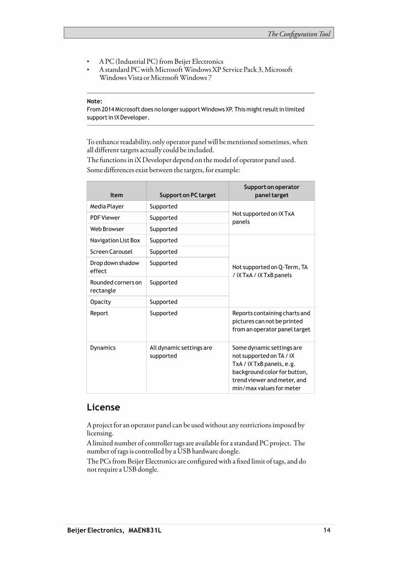
To enhance readability, only operator panelwill bementioned sometimes, whenall different targets actually could be included.The functions in iXDeveloper dependon themodel of operator panel used.Somedifferences exist between the targets, for example:
Item Support onPC targetSupport onoperator
panel target
MediaPlayer Supported
PDFViewer Supported
WebBrowser Supported
Not supportedon iXTxApanels
Navigation List Box Supported
ScreenCarousel Supported
Dropdown shadoweffect
Supported
Roundedcorners onrectangle
Supported
Opacity Supported
Not supportedonQ-Term,TA/ iXTxA/ iXTxBpanels
Report Supported Reports containing charts andpictures cannot beprintedfromanoperator panel target
Dynamics All dynamic settings aresupported
Somedynamic settings arenot supportedonTA/ iXTxA/ iXTxBpanels, e.g.backgroundcolor for button,trend viewer andmeter, andmin/maxvalues formeter
License
Aproject for an operator panel can be usedwithout any restrictions imposed bylicensing.A limited number of controller tags are available for a standardPCproject. Thenumber of tags is controlled by aUSBhardware dongle.The PCs fromBeijer Electronics are configuredwith a fixed limit of tags, and donot require aUSBdongle.
Beijer Electronics, MAEN831L 14

TheConfigurationTool
Thenumber of used controller tags (includingDEMOcontroller tags) is shownin the lower right of the desktop. The figureswill turn red if the number of usedtags becomes greater than the number of available tags.There are no license restrictions for internal tags.
Related information
Internal Tags
DEMOController
ProductRegistration
Thefirst time iXDeveloper is started, a registration dialog is displayed. Enteringthe registration key provides unlimited access to all program functionality andsoftware updates.Alternatively, select to continue using a trial version of the software. Youmayevaluate iXDeveloperwith full functionality for 30 days. When the evaluationperiod has expired, it will still be possible to use the software, but the functions intheRun andTransfer groupswill be disabled.
Note:If youhavealreadyusedaDemoversionof iXDeveloper for 30days, youwill not beissuedanother 30days for evaluation.
Project Size
The project size is shown in the lower right of the desktop areawhen designing anoperator panel project. The sizewas calculated at the latest validation.
1.1.5 Installation
The iXDeveloper software is supplied on aUSB stick. When connecting theUSBstick to theUSBport, the installation starts automatically. Follow the instructionsto install iXDeveloper. If the installation does not start, run the setup.exe file.The installation creates an icon for iXDeveloper in the groupnamed iXDeveloper.Click on Start/All Programs/iXDeveloper 2.10/iXDeveloper 2.10 to start iXDeveloper.
Note:The iXDevelopermust be installedonadevelopmentPC, a iXTxC target cannot beused todevelopprojects.
Beijer Electronics, MAEN831L 15

TheConfigurationTool
Installationof iXRuntime
To install iXRuntime on a PC, insert the iXDeveloperUSB stick and select toinstall iXRuntime. To run the program, a dongle is required that is supplied byBeijer Electronics.
Note:iXDeveloper cannot be runon the samePCas iXRuntime.
Note:Whenusing iXRuntimeonaPC it is recommended touninstall a previous iXRuntimebefore installing anewversion.
1.1.6 ConfiguredFeatures
iXDeveloper offers the possibility to add customer-specific features in theprogram. This is done through the use of registration keys that are entered afterthe iXDeveloper software installation has been done.Clicking onShowFeaturesdisplays a list of enabled features. To install a newfeature, enter the feature registration key underConfiguredFeatures and clickOK.A restart of the program is required to activate the function.
Related information
About
1.1.7 Project
The top folder for a specific application designedwith iXDeveloper is referredto as the project folder.During runtime, project database files can be updated, for examplewith newrecipes. Thismeans that to completely reproduce a project that has been inoperation, itmay be necessary to combine source fileswith files retrieved fromthe operator panel.
Beijer Electronics, MAEN831L 16

TheConfigurationTool
1.1.8 File Structure
Aproject contains a set of files related to the functional and graphical design anda set of files related to the runtime operation of the project, where the latter iscompiled from the design files.
ProjectFolder
When anewproject is created, a folderwith the project name is created as thetop-level container, theProject folder. The files that define the functional andgraphical design reside in the top level of the project folder. Other folders arecreated as a result of validation and build.
Symbols
Pictures that are used in projects are converted to .png files when the project isvalidated.Pictures are resized to the largest static usage in any of the project screens, inorder to savememory space in the panel. If a picture is enlarged in runtime usingdynamics, the enlarged picturewill have a lower effective resolution.Project pictures are stored in theSymbols folder as a compressed folder namedSymbols.zip.
Temp
TheTemp folder contains intermediate build files fromproject compilation.TheTemp folder also includes theOutput folder. TheOutput folder contains allfiles needed to run the project in the target. These files are copied to an operatorpanel when theTransfer command is used. For a PC, theTransfer to foldercommand is used to copy the necessary files to aUSB stick to the runtimePCviaa network connection.
Note:It is necessary to openports in thefirewall for the runtimePCapplication.
MovingDesignFiles
Tomove the project files needed for the design:1. Create a new folder for the project design files.2. Copy all single files (files not included in any folders) aswell as all folders,
except theTemp folder, in the project folder.3. Paste the files in the new folder.
MovingApplicationProject
The runtime project can be downloaded to the operator panel using the transfer orexport commands, but can also bemovedmanually:1. Create the new folder for the project files.2. Copy theOutput folder.
Beijer Electronics, MAEN831L 17
TheConfigurationTool
3. Paste it in the new folder.
Database
The database used for iXDeveloper projects is of SQLServerCompact Editiontype. The contents of the database can bemanagedwith third-party databasemanagement tools. iXDeveloper includes a database viewer object that can beused to display database contents in runtime.The database is initially transferred to the operator panel using the transfercommand. The databasewill only be updated if there are changesmade in theproject that affects the database contents, for example:• Changed or added recipes• Changed or addeddata loggers• Changes to alarmhandling• Changed or added trend viewers
A copy of the database can bemadewith theUploadDatabase command. Someof the databases can be exported individually in csv, comma separated values,format using theDatabase Export action. If possible, it is recommended to use thedatabase export action rather than the backupdatabase action.
Related information
DatabaseViewerObject
Download
Export
UploadDatabase
DatabaseExport
Beijer Electronics, MAEN831L 18

Workingwith Projects
2 WorkingwithProjects
This section describes iXDeveloper and explains how toworkwith a project foran operator panel.In iXDeveloper, ribbon tabs are used instead ofmenu commands. This reducesthe number of steps needed to design complex components, and also supplies anattractive user interface.Ribbon tabs are located in the top section of the tool window. Each ribbon tabholds one or several control groups. Each group contains a set of related controls.Controls aremade to design screens, and tomake settings for objects and controlsin the project.
2.1 CreatingaProject
Aproject can be created according to the following sections, but thework processcan be adapted and rearranged if needed.
2.1.1 Connecting toaController
Establishing communication between an operator panel and controller isnecessary to allowoperator observation and control. The larger the project is, themore important it is to ensure that there is a suitable communication design.There is a built-inDEMOcontroller in iXDeveloper. It can be used for test andsimulation purposes.
Related information
Creating aNewProject
SelectController
CommunicationDesign
DEMOController
2.1.2 DesigningaScreenSet
It is important to organize the applicationwell and to considerwhich functions arenecessary. Startwith an overall view and thenwork down to a detailed level.A project contains a number of screenswith objects that can exchange datawiththe controller. Screens can be arranged in hierarchies to achieve a structuredapplication, or organized as sequence controls. Whendecidingwhich structureto use, consider how to best describe the process at hand and how to simplifyprocedures for themachine operator.The complete application, or parts of it, can be tested in the developmentenvironment before downloading it to the operator panel.
Related information
Screens
Beijer Electronics, MAEN831L 19

Workingwith Projects
2.1.3 DesigningAdditional Functions
Alarms
Alarms are used tomake the operator aware of events that require immediateaction. An alarm is set when a certain condition ismet. An alarm condition isdesigned as a logical evaluation of a tag value. Alarms can be divided into groupsto create an order of priority.
Related information
AlarmManagement
FunctionKeys
Function keys can be used to performactions and execute scripts. This allowsoperator control of data and screen functionality independent ofwhich screenis active.
Related information
FunctionKeys
MultipleLanguages
Translation of texts and system texts can be performed directly in the application,or via export to a text file to be translated in other software. The file is importedto the application after translation. The application language can be changed inruntime, for example based on a tag value.
Note:Pre-translated systemtexts areprovidedwith iXDeveloper. These texts are adaptedfor aPC,whichmeans that they containmore strings thanwhat is available for paneltargets. This results inwarningswhen importing the systemtexts toprojects createdfor apanel, but thesewarnings can safely be ignored.
Related information
LanguageManagement
Security
Access to objects and actions in the project can be limited using security groupsand user passwords.
Related information
SecurityManagement
TextLibrary
With the text library function, text tables can be created,where values are linkedto texts.
Beijer Electronics, MAEN831L 20
Workingwith Projects
Related information
Text Library
AuditTrail
TheAudit Trail function allows tracking of operator actions.
Related information
Audit Trail
DataLogger
Data can be logged and saved to file. Bit, 16-bit, 32-bit andReal (Float) values canbe logged. Be aware that logging of data consumes system resources andmemory.
Related information
Data Logger
Scheduler
Setting and resetting digital tags in relation to the real-time clock can be performedusing a scheduler, in order to control events in the process at special calendar times.
Related information
Scheduler
Recipes
Recipes are used to set or save a predefined group of tags in one operation.Values can be predefined or collected from the controller, and then saved to arecipe in the operator panel. The operator can download the recipe at any time tothe controller, whichwill start workingwith the recipe values. Recipe handlingmakes it possible to reuse large parameter sets, to improve efficiency of time criticalproductionwhere a change of productsmust bemade quickly. Recipe files can becreated in the development project orwith the operator panel.
Related information
RecipeManagement
Reports
The reports function allows adding excel report templates to the project.
Related information
Reports
Beijer Electronics, MAEN831L 21

Workingwith Projects
2.2 Importingan InformationDesignerProject
Existing InformationDesigner projects can be imported to iXDeveloper.InformationDesigner is the previous software used to design projects for theEXTERoperator panels.The import function is accessed from theWelcomepage, displayedwhen startingiXDeveloper.1. Select the InformationDesigner project file.2. Select a name and location for the imported project.3. ClickFinish.
The project will be imported to the corresponding iXpanel target. All screenswill be imported and graphical objects in the InformationDesigner project willbe converted to corresponding iXDeveloper objects. Some objectsmay not besupported.Functions such as recipes and data loggingwork differently in iXDeveloper, andwill have to be reconfigured in the imported project.During the import, a log file of unsupported objects and functions is created. Itcan be saved to disk for future reference.
Note:If there is a crashwhen importingan InformationDesigner project, theproblemcouldbe solvedby installing a hotfix fromhttp:/ /support.microsoft.com/kb/2461678.
Beijer Electronics, MAEN831L 22
Workingwith Projects
2.3 ImportinganH-Designer/ADPProject
ExistingH-Designer/ADPprojects can be imported to iXDeveloper.H-Designer/ADP is the previous software used to design projects for theH-/PWS-series operator panels.The following software versions are required:
Software Version
ADP 6.50build 184
iXDeveloper 2.0 orhigher
2.3.1 Exporting theH-Designer/ADPProject
First, theH-Designer/ADPproject has to be converted to an a2i file fromwithinADPby following the steps below:1. SelectFile/Export iX.2. Select a name and location for the export file, and clickOK.
Amessage box confirms that the export is finished, and after clickingOK, youare asked if youwant to see the log file. The log file is saved to the same locationas the project file.The log file declares successfully converted items aswell as unsupportedobjects and functions.
2.3.2 Importing thea2iFile
Then, the exported file is imported into iXDeveloper using the import functionthat is accessed from theWelcomepage, displayedwhen starting iXDeveloper.1. Select the a2i file.2. Select a name and location for the imported project.3. ClickFinish.The project will be imported to the corresponding iXpanel target. All screenswill be imported and graphical objects in theH-Designer/ADPproject will beconverted to corresponding iXDeveloper objects. Some objects and functionsmaynot be supported at all, and some objects and functions need reconfiguring inthe imported project.During the import, a log file of unsupported objects and functions is created. Itcan be saved to disk for future reference.
2.3.3 Limitations
All parts of the originalH-Designer/ADPproject will not be fully supported in iXDeveloper. For example, for objects that use individual controller registers for readandwrite, only the register selected forwrite will be connected. Also, patterns andother decoration of objectsmaynot be included in the imported project.The following functions and objectswill not be converted, orwill needreconfiguration:
Beijer Electronics, MAEN831L 23

Workingwith Projects
Function Comment
Controller Import of name list andaddresses for thefirst twocontrollers in theADPproject issupported.
Import of controller settings suchas IP addressandCOMsettings is not supported.
Import of index registers is not supported.
Macro and sub-macro Not supported
Recipes Not supported
Object Comment
Actionpushbutton Thegraphical controlwill be importedbut theactions need tobe reconfigured.
Alarmhistory table, active alarmlist, alarm frequency table andalarmmarquee
Not supported
Animatedgraphic Not supported
Bar graphdeviation Thegraphical controlwill be importedbutneeds tobe reconfigured.
Day ofweekdisplay Thegraphical controlwill be importedbutneeds tobe reconfigured.
Dynamic ellipse anddynamicrectangle
Not supported
Historical data table andhistoricalevent table
Not supported
Moving sign Not supported
Multistate indicator Not supported
Pie graph Not supported
Set valuepushbutton Not supported
Seven segments Not supported
Trendgraph Thegraphical controlwill be importedbut thecurves need tobe reconfigured.
X-Y chart Not supported
Shape Comment
Arc Not supported
Free form Not supported
Parallelogramand solidparallelogram
Not supported
Pie and solid pie Not supported
Scale Not supported
Beijer Electronics, MAEN831L 24

Workingwith Projects
Shape Comment
Shape Not supported
Solid polygon Thegraphical controlwill be importedbutneeds tobe reconfigured.
2.4 OptimizingPerformance
The following section presents a couple of issues to consider in order to optimizethe iXDeveloper project. Someparts are related to the communication driver;other parts concernCPU load andflash operations.
2.4.1 CommunicationPerformance
SignalTypes
Tags used for driver communication can be static or dynamic. These are updatedin differentmanners.
StaticTags
Static tags are updated continuously, even if they are not currently shownon thepanel display.Additionally, the operator panel reads the following items continuously:• Alarm tags• Data logger tags• Multiple languages tags• Controller tagswith value change events
The communication time is not affected by the following:• Alarmmessages• Schedulers• Tags linked to function keys
DynamicTags
Dynamic tags are updated onlywhen they are presented on the display. An analognumeric object serves as an example ofwhen a dynamic tag is used.
2.4.2 CommunicationDesign
This section describes how tags are read and how the reading can be optimized tomake the communication between the operator panel and the controller fast andefficient.
KeepingTags inConsecutiveOrder
Define controller tags consecutively, for exampleM0.0-M11.7. If the tags arespread (e.g. I0.4,Q30.0,M45.3 etc.) a complete updatewill take longer time.The number of tags in each package depends on the used driver and informationabout this can be found in the driver help file.
Beijer Electronics, MAEN831L 25

Workingwith Projects
TagPackages
Tags to be transferred are not all transferred at the same time, but are groupedinto packages. The number of tags in each package depends on the driver for thecontroller.Tomake communication as fast as possible the number of packages should beminimized. Consecutive tags require aminimumnumber of packages, but it isperhaps not always possible to program it this way. In such cases there is a “waste”between two tags.
Waste is themaximumdistance between two tags that can be kept in the samepackage. The size of thewaste depends on the driver used, and is included in thedriver help file, e.g as in the table below:
Driver x Analog signals Digital signals
Number of signals/package 29 124
Waste 20 0
Bit-AddressedWordsvs. RegularBitDevices
Inmost drivers it is better to use bit-addressedwords than regular bit devices, sinceyou can fitmore digital devices in one telegramwhen using bit-addressedwords,thanwhenusing bit devices.
Example
Driver x Analog signals Digital signals
Number of signals/package 29 124
Waste 20 0
This specific driver can have 29 analog devices or 124 digital devices in onetelegram. If you use bit-addressedwords in the selected driver, you canfit 464(29 × 16) digital devices in one package. This is almost four times asmany devices.
ASCII Strings
ASCII strings are transmitted in separate telegrams, and having a large numberof stringswill affect the communication performance negatively. If anASCIIstring only has a small number of different string values, itmay be a good idea touse theText Library function in iXDeveloperwith predetermined contents, thusminimizing impact ondriver performance.
Related information
Text Library
Beijer Electronics, MAEN831L 26

Workingwith Projects
2.4.3 Performance in theoperatorpanel
It is important to understand that due to the complex nature of a running system,there are several things that affects the overall performance. The following listgives some examples of things to consider, when it is necessary improve theperformance of the operator panel:• Number of tags• Number of sampled tags in trend viewers and data logger• Number of alarms• Driver performance• Multiple drivers• Type of panel• Alarm list size• Size of pictures• Scripts
PollGroups
The default setting in iXDeveloper updates all tags every 500ms. If some tagsmay be updated less often, it is possible to assign them to a poll groupwith a lowerupdate interval. Poll groups are configured in theTags configuration page.
Screens
Optimizing screen update timeminimizesCPU load andflash operations. Thiscanmake a significant difference in graphic-intense projects that approach thelimits of the panel’s capabilities.Screen changes are carried outmost efficiently through a show screen action, eitheron a function key or an object.
TrendViewersandDataLoggers
Several trend viewers can showdata from the same log item.In order to improve performance in the panel, it is strongly recommended to placeall log items logged on the same frequency/event in the same data logger or at leastreduce the amount of data loggers.Try to avoid having one data logger for each trend viewer.
Beijer Electronics, MAEN831L 27

Workingwith Projects
Gradients
Using objects with gradients creates a slightly higher load on theCPU. If a largenumber of objects use gradients, this willmake the screen update time significantlyslower. Pay special attention to objects with gradients that are updated frequently,e.g. a bar graphwith a stylewith gradients connected to a tag that changes at shortintervals.
Reports
Using the reports function in a project will result in an increased panel startuptime.
Related information
ActionGroups
TrendViewer
Reports
Data Logging Strategies
Symbols
2.5 MovingObjectswith theTouchScreen
iX panels with touch screens donot have a built-in keyboard. Allmaneuveringis donewith the touch screen by pressing distinctlywith a finger. Because of theresistive touch technology, the screen can only apprehend pressing on one place onthe panel at the time. Pressing two points at the same time is interpreted by thepanel as a pointmidway between the twopressed points.
Related information
2.5.1 OperateObjects
For an object to react, it is necessary to specify the behavior, typically by assigninga tag anddefining an action. All objects can have actions linked tomouse down,mouse up,mouse enter andmouse leave events. Some objects have a predefinedbehavior, like sliders setting values, but can also have actions linked tomousedown andmouse up events.
Button
Pressing a button triggers a click- andmouse button event.
TextBox
Pressing on a text box object displays a virtual alpha-numeric keyboard on thepanel screen. Type a text using this keyboard and finish by pressing [ENTER].
Beijer Electronics, MAEN831L 28

Workingwith Projects
AnalogNumeric
Pressing on an analog numeric object displays a virtual keyboard on the panelscreen. The keyboard type depends on the format chosen for theAnalogNumeric—String, Integer,Decimal,Hex orBinary. Enter a value using this keyboard andfinish by pressing [ENTER].In runtime a validation of the value is done. If the value entered is out of bounds,the corresponding limit value for the object will be shown.
Slider
Pressing on the desired value position of a slider object sets it to the pressedposition.
Related information
ActionsRibbonTab
MouseButtonActionTriggers
ClickActionTrigger
Virtual Keyboard
ValidationGroup
2.6 Peripherals
2.6.1 USB
External devices such as aUSBhub, flash drive,mouse, or keyboard can beconnected to theUSBhost port.
2.6.2 Ethernet
The operator panel has built-in Ethernet port(s) for connection to controllers viaTCP/IP.The number of ports varies bymodel.
Related information
IP Settings
2.6.3 MemoryCard
An externalmemory card can be used as storage of e.g. pdf files andmedia files, toreduce used internalmemory. Access to the files on the externalmemory card isavailable via scripting.
Related information
ProjectGroup
Beijer Electronics, MAEN831L 29

Development Environment
3 DevelopmentEnvironment
This section describes how toworkwith iXDeveloper.Clicking theOptions button in the Filemenu allows adapting the tool behavior.
Related information
FileMenu
Options
3.1 Starting iXDeveloper
Click on Start/All Programs/iXDeveloper 2.10/iXDeveloper 2.10 to start iXDeveloper.iXDeveloper can also be started from the command line.When iXDeveloper is started, it is possible to:• Create a newproject using awizard• Open an existing project - a list of recently opened projects is displayed• Open a sample project• Upload a project from a target• Import a project created in InformationDesigner• View theUser’sGuide, based on an example project that serves as an
instructive introduction to iXDeveloper
Projects can also be created or opened later from the Filemenu.
Related information
Creating aNewProject
Importing an InformationDesigner Project
Starting iXDeveloper fromtheCommandLine
Upload fromTarget
Beijer Electronics, MAEN831L 30

Development Environment
3.1.1 Creating aNewProject
To create a newproject using thewizard includes the following steps:1. Start iXDeveloper.2. Select to create a newproject.3. Select target for the project.4. Select controller brand andmodel.5. Name the project anddefinewhere files are to be saved in the PC environment.
Selectoperatorpanel
Select the appropriate target from the presented set of operator panel/PC.
The target can be changed later, from the Settings group on theProject ribbon tab.Whenworkingwith a project for panel T7A,T10Aor iXTxB, it is possible toselect the rotation of the panel from adrop-down list.Whenworkingwith a project for a standard PC, it is possible to select resolutionfrom a drop-down list. The PC resolution can be changed later, by entering theSettings group on theProject ribbon tab.
Related information
ChangingProjectTarget
SelectController
Select the appropriate controller for the project.
Beijer Electronics, MAEN831L 31

Development Environment
The demo controller, including regular tags (data containers) and counters, is usedto design and test a project directly on the development PCwithout connection toan external controller.Internal tags thatwork like controller tags, but are independent of an externalcontroller, can be defined.It is also possible to connect to an externalOPC server.The controller can be changed later by clicking theController button on theControllers tab of the tags configuration page.A project can connect tomore than one controller. To set upmultiple controllers:
Related information
Controller
DEMOController
InternalTags
ExternalOPCServer
MultipleControllers
Select Location
TheSelect Location dialog controls naming of the project andwhere project filesare saved in the computer environment.
Beijer Electronics, MAEN831L 32

Development Environment
1. Change the project name, if desired.2. Select where to store the project files by clickingBrowse, or accept the
suggested location.3. ClickFinish to create the newproject.
3.1.2 OpeningaProject
Toopen an existing project using thewizard includes the following steps:1. Start iXDeveloper.2. Select to open a project.3. Browse to the project file in the appearing “open project” dialog.
Note:It is possible to openacompressedZIPfile of the iXDeveloper project. Theuserwill beprompted for apathwhere theZIPfile canbedecompressed.
Related information
Compress Project
Download
3.1.3 GettingFamiliarwith iXDeveloper
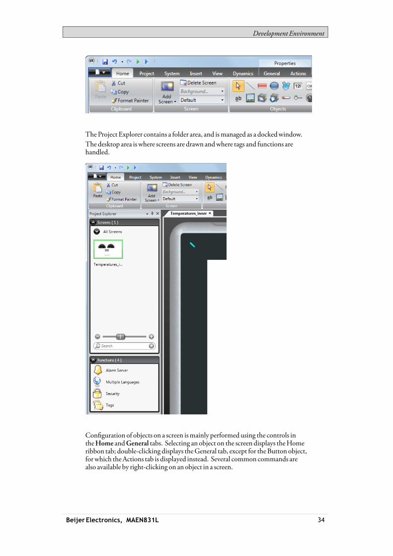
The ribbon tabs (e.g. Home,System and Insert) are located in the top of thewindowwhen iXDeveloper is started. The control groups (e.g. Clipboard,Screen,Objects on theHome ribbon tab) are available in the ribbon area.
Beijer Electronics, MAEN831L 33
Development Environment
TheProject Explorer contains a folder area, and ismanaged as a dockedwindow.The desktop area iswhere screens are drawn andwhere tags and functions arehandled.
Configuration of objects on a screen ismainly performed using the controls intheHome andGeneral tabs. Selecting an object on the screen displays theHomeribbon tab; double-clicking displays theGeneral tab, except for theButton object,for which theActions tab is displayed instead. Several common commands arealso available by right-clicking on an object in a screen.
Beijer Electronics, MAEN831L 34

Development Environment
Related information
Project Explorer
PositioningWindows
Screens
Tags
KeyboardNavigation
PressingAlt on the keyboard displayswhich keyboard shortcut commands can beused to execute a command or to enter a control group, e.g. Alt + F opens theFilemenu, andAlt + I displays the Insert ribbon tab control groups.
KeyboardShortcuts andFunctionKeyCommands
The list below includes some of the keyboard shortcuts and function keycommands that are available in iXDeveloper:
Keyboard shortcut /
functionkey Description
Ctrl + P,
[number of thescreen]
Switchbetween screens according to their order on thedesktop
Ctrl + E, L Lock selectedelements on active screen (E indicates activeeditor)
Ctrl + E,H Hide selectedelements on active screen (E indicates activeeditor)
Ctrl + Z Undo
Ctrl + Y Redo
Ctrl +A Select all
Ctrl + X Cut
Ctrl +C Copy
Ctrl +V Paste
Ctrl +N Newproject
Ctrl +O Openproject
Ctrl + S Saveproject
Ctrl + B Bold style
Beijer Electronics, MAEN831L 35
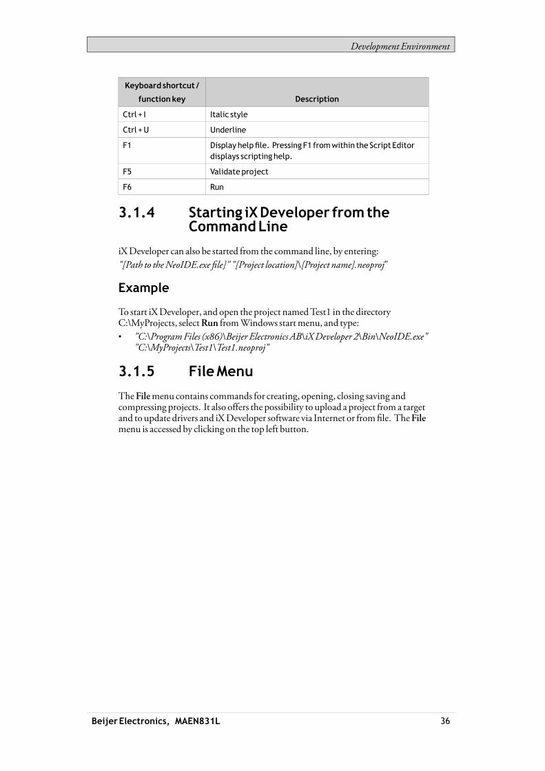
Development Environment
Keyboard shortcut /
functionkey Description
Ctrl + I Italic style
Ctrl +U Underline
F1 Display helpfile. Pressing F1 fromwithin the Script Editordisplays scripting help.
F5 Validate project
F6 Run
3.1.4 Starting iXDeveloper fromtheCommandLine
iXDeveloper can also be started from the command line, by entering:"[Path to theNeoIDE.exe file]" "[Project location]\[Project name].neoproj"
Example
To start iXDeveloper, and open the project namedTest1 in the directoryC:\MyProjects, selectRun fromWindows startmenu, and type:• "C:\ProgramFiles (x86)\Beijer Electronics AB\iXDeveloper 2\Bin\NeoIDE.exe"
"C:\MyProjects\Test1\Test1.neoproj"
3.1.5 FileMenu
TheFilemenu contains commands for creating, opening, closing saving andcompressing projects. It also offers the possibility to upload a project from a targetand to update drivers and iXDeveloper software via Internet or fromfile. TheFilemenu is accessed by clicking on the top left button.
Beijer Electronics, MAEN831L 36

Development Environment
New
When you start iXDeveloper and select to create a newproject, a wizard guidesyou through the creation of a newproject, in the sameway as having selectedCreateNewProject from theWelcomepage.
Related information
Creating aNewProject
Open
SelectingOpen displays a dialog that allows selection of an existing project fileby browsing.
Save
Selecting Save saves the project to the current project folder.
SaveAs
Selecting SaveAs allows saving the projectwith a different name and/or in adifferent location.To ensure that the original project remains unchanged, the newproject filemustbe createdwith theSaveAs commandbeforemodifying its contents.Creating a new folderwhen using the Save as commandhelps keeping the largenumber of project files neatly collected and easy to overview.
Beijer Electronics, MAEN831L 37

Development Environment
Note:Selecting Saveas cannot beused inorder tomakemodifications of anexisting project,keeping theoriginal project unchanged, and saving thenewversionwith anothername. Changeswill affect theoriginal project anyway. It is recommended tomakeabackupcopyof theoriginal project, for examplebyusingWindowsExplorer, prior tomodifying it.
CompressProject
SelectingCompress Project compresses the project and saves it as a ZIP file. Theuserwill be prompted for a pathwhere to save theZIPfile andwill also be offeredthe possibility to password protect theZIPfile.
Related information
Compress Project
Upload fromTarget
SelectingUpload fromTarget allows uploading a compressedZIPfile of a projectfrom a connected target.
Note:Tobeable touse the“Upload fromtarget” function, the checkbox“Download allsource code”on the“Download”dialogmust havebeenclickedbeforedownloadingtheproject to anoperatorpanel. See the “Download”chapter formore information.
Beijer Electronics, MAEN831L 38
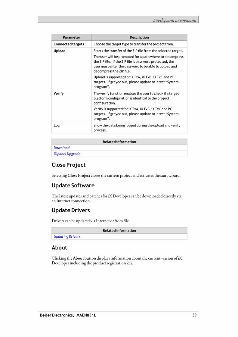
Development Environment
Parameter Description
Connected targets Choose the target type to transfer theproject from.
Upload Starts the transfer of theZIPfile from the selected target.
Theuserwill beprompted for a pathwhere todecompresstheZIPfile. If the ZIPfile is passwordprotected, theusermustenter thepassword tobeable toupload anddecompress theZIPfile.
Upload is supported for iXTxA, iXTxB, iXTxCandPCtargets. If greyedout, please update to latest “Systemprogram”.
Verify Theverify functionenables theuser to check if a targetplatformconfiguration is identical to theprojectconfiguration.
Verify is supported for iXTxA, iXTxB, iXTxCandPCtargets. If greyedout, please update to latest “Systemprogram”.
Log Show thedatabeing loggedduring theuploadandverifyprocess.
Related information
Download
iXpanelUpgrade
CloseProject
SelectingCloseProject closes the current project and activates the startwizard.
UpdateSoftware
The latest updates and patches for iXDeveloper can be downloaded directly viaan Internet connection.
UpdateDrivers
Drivers can be updated via Internet or fromfile.
Related information
UpdatingDrivers
About
Clicking theAbout button displays information about the current version of iXDeveloper including the product registration key.
Beijer Electronics, MAEN831L 39

Development Environment
Note:Theactiveproject needs tobe saved inorder to access the list of features.
Note:If an iXDeveloper version 2.0based featurehaspreviously been installed, theregistration keywill automatically be convertedwhenupgrading to iXDeveloperversion2.10.
Options
Clicking theOptions button allowsmaking settings that control the behavior andappearance of iXDeveloper.
LanguageOptions
Select inwhich language to run iXDeveloper. A restart of the application isrequired for the new language selection to have an effect.
BuildOptions
Selectwhether theCheckForUnusedTags function should be activated or not.When building a project, the function checks for unused tags and presents a dialoginwhich it is possible to remove these.
Related information
RemovingUnusedTags
ScriptDebuggerOptions
• Arguments: The “%1” argument is where the file namewill be inserted. Thisoption is applicable onlywhenCustom is selected forDebuggerType.
• Debugger: Full path to the current debugger application.• DebuggerType: SelectDefault orCustom. With theDefault setting, the
systemwill automatically provide the path to the debugger, if found. Customallows the user to provide the path to a specific debugger.
TagsEditorOptions
Selections underTags EditorOptionsmakes it possible to customizewhichcolumns to showby default in the tags configurationwindow.
Beijer Electronics, MAEN831L 40

Development Environment
RibbonOptions
• GoToDefaultRibbonStrategy: This option changes the active ribbonbasedon the context of the selection in the desktop. When an object is created orselected, theGeneral tab tabs becomes active in the ribbon area.
• SimpleRibbonStrategy: This is the default setting, and does not swap theactive ribbonwhen the context of the current desktop selection changes.Clicking on an object opens theHome ribbon, and double-clicking openstheGeneral ribbon formost objects, but for buttons theActions ribbon isactivated.
ScreenEditorOptions
• EnableInPlaceEditing: This option allows editing an object directlywhenselecting it on the screenwithout having to access its properties on e.g. theGeneral ribbon tab.
• ShowPanelAround: This option displays an outline of the selected panelmodel around the desktop area.
• ShowSizeAndDistanceInformation: The size of an object is displayedwhileresizing it. Distance to the edges of the desktop area is displayedwhenmovingan object. The indication can be turned off, if desired, by setting this optiontoFalse.
• ShowToolTips: Useful tool tips are automatically displayed in iXDeveloper.These can be turned off, if desired, by setting this option to False.
The screen editor options can also bemodified using buttons in the lower part ofthe desktop area.
Related information
ScreenView inDesktopArea
MiniToolbarOptions
Themini toolbar is a contextmenu additionwith a subset of common controlsfrom theFormat,Tag/Security andName groups.• ShowMinitoolbarAutomatic: When this option is set toTrue themini
toolbar part of the contextmenu is displayed alreadywhen an object isselected. Themini toolbarwill always show in combinationwith the contextmenu. Themini toolbarwill remain active for a selected object, also afterit has disappeared, until the selection or the pointermoves away. To showthemini toolbar againmove themouse pointer to the upper right of theobject. With the default setting,False, themini toolbarwill only show incombinationwith the contextmenu for an object.
Exit
Clicking theExit button closes the application. If there are unsaved changes, youare asked if youwant to save thembefore exiting.
3.1.6 QuickAccessToolbar
TheQuickAccessToolbar contains controls, expected to be used frequently. Thetoolbar can be customized to include other buttons.
Beijer Electronics, MAEN831L 41

Development Environment
Save
Saves the current project to the location specifiedwhen the project was created.
Undo
Executed commands can be undone using theUndo button. Clicking the smallarrow at the right of theUndobutton lists recentlymade changes for selection ofthe undo operation.
The keyboard shortcut forUndo isCtrl +Z.
Redo
Acommand that has been undonewithUndo can be redonewithRedo. Thekeyboard shortcut forRedo isCtrl +Y.
Run
Performs a validation of script code and compiles the project. If the project is valid,a simulation is started on the development PCwith connection to the selectedcontroller. Also available from theTransfer/Test group on theProject ribbon tab.
Simulate
Performs a validation of script code and compiles the project. If the project is valid,a simulation is started on the development PCwithout connection to the selectedcontroller. Also available from theTransfer/Test group on theProject ribbon tab.
Related information
ProjectRibbonTab
CustomizingQuickAccessToolbar
Some of the ribbon controls can be added to theQuickAccess Toolbar. Right-clickon the desired control and selectAdd toQuickAccessToolbar orRemove fromQuickAccessToolbar.
Beijer Electronics, MAEN831L 42

Development Environment
3.1.7 RibbonTabs
The ribbon tabs contain grouped controls for editing andmaintaining a project,screens and objects. Click on any ribbon tab to display the ribbon.UseMinimize theRibbon andMaximize theRibbon to collapse and expand theribbon control tabs, or double-click on a ribbon tab. This can also be done fromtheQuickAccess toolbar.
Related information
HomeRibbonTab
ProjectRibbonTab
SystemRibbonTab
InsertRibbonTab
ViewRibbonTab
DynamicsRibbonTab
General RibbonTab
ActionsRibbonTab
QuickAccess Toolbar
3.1.8 Additional Properties
Some ribbon groups include additional properties that can be configured byclicking the small arrow in the lower right corner of the current group.
The propertieswindowdisplays available property groups available for selectionat the left. The property groups available differ depending onwhich object isselected.
Beijer Electronics, MAEN831L 43

Development Environment
3.2 DesktopArea
The desktop area displays screens and configuration pages for project componentssuch as controllers and functions. The desktop area shows only one screen orcomponent at a time. Whenmultiple screens or components are opened a rowoftabs are shown in the upper part of the desktop area. Clicking on a tab activatesits contents for editing.If there aremore tabs open than can be displayed, navigation arrows in the upperpart of the desktop area can be used to scroll between them.
3.2.1 ScreenView inDesktopArea
Object appearance aswell as size and appearance of the current screen can bemanaged by controls in the lower part of the desktop area. It is also possible toturn on and off the in-place editing function that allows editing text in an objectdirectlywhen selecting it on the screen.
Show/HideSizeandDistance Information
The size of an object is displayedwhile resizing it. Distance to the edges of thedesktop area is displayedwhenmoving an object.
ShowSize andDistance Information is activated
Beijer Electronics, MAEN831L 44
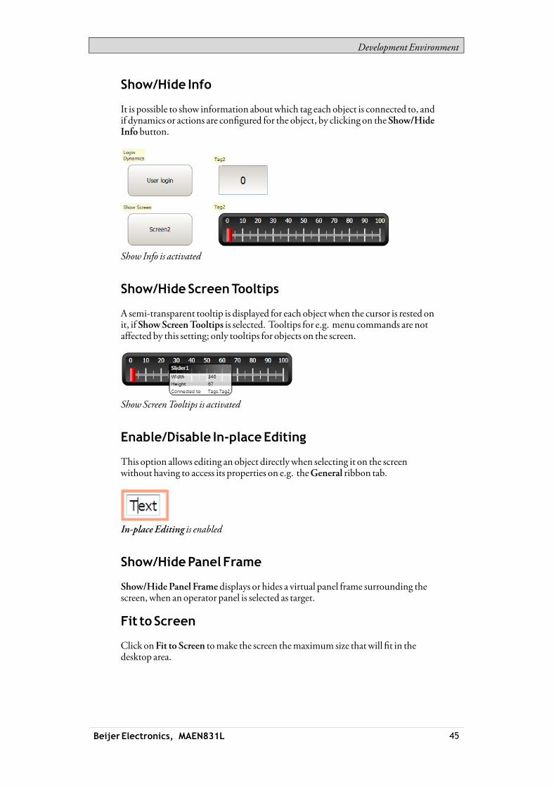
Development Environment
Show/Hide Info
It is possible to show information aboutwhich tag each object is connected to, andif dynamics or actions are configured for the object, by clicking on theShow/HideInfo button.
Show Info is activated
Show/HideScreenTooltips
A semi-transparent tooltip is displayed for each object when the cursor is rested onit, if ShowScreenTooltips is selected. Tooltips for e.g. menu commands are notaffected by this setting; only tooltips for objects on the screen.
ShowScreenTooltips is activated
Enable/Disable In-placeEditing
This option allows editing an object directlywhen selecting it on the screenwithout having to access its properties on e.g. theGeneral ribbon tab.
In-place Editing is enabled
Show/HidePanel Frame
Show/HidePanel Frame displays or hides a virtual panel frame surrounding thescreen, when an operator panel is selected as target.
Fit to Screen
Click onFit to Screen tomake the screen themaximum size thatwill fit in thedesktop area.
Beijer Electronics, MAEN831L 45

Development Environment
Zoom
The followingmethods can be used to zoom in to or out from the desktop area:• Selecting a set zoomvalue from theZoom drop-down list.• Setting theZoomSlider to a desired zoom level.• Clicking theZoom In andZoomOutbuttons.• Placing themouse pointer anywhere in the screen and using the scroll wheel.
Pan
Panning of the current screen is possible in Layoutmode, if the screen is larger thanthe desktop area.• Press and hold [Spacebar] (themouse pointer will change its appearance from
an arrow shape to an open hand).• Drag to pan the screen (themouse pointer hand closes in panningmode).
3.2.2 DesktopViewModes
Screens and functions have different viewmodes. The default setting isLayoutviewmode, but screens and functions can be partly viewed and edited directly incode. The desiredmode is selected from the lower left part of the desktop area.The code for screens is in xaml and inC# for script.
Desktop viewmode tabs
Caution:Incorrect codeentered in textmode (Xamland Script)may result in errors that arenotpossible to recognizeduring analysis andbuild.Erroneous codemay result in unpredictable behavior and loss of data.
Layout
Screens and objects are usually edited inLayout viewmode.
XAML
A screen layout is defined inXAML (eXtensible ApplicationMarkupLanguage)code. The .xaml files are stored in the project folder.XAMLcode can be added and changed in theXaml viewmode. Any changes donein theXAMLcodewill affect the screen layout.
Script
In Script viewmode scripted actions can be configured for screens, objects, tags,function keys etc.
Beijer Electronics, MAEN831L 46

Development Environment
Note:Todisplay a script guide that describes iXDeveloper scriptingpossibilities in detail,select Script viewmode, click anywhere in the code, andpressF1.
Caution:Beijer Electronics only offers support for scripting for the includedexamples in iXDeveloper
Objects that can trigger events will showwith expandable nodes in theScript view.Clicking the [+] of such a node expands it and shows the trigger events for theobject. Double-clicking on an event inserts itsmethod headingwith an emptycode body. Scripts arewritten inC# syntax.When actions are defined for an object, this will have precedence over script code.
Note:Avoidusingmultiple triggermethods as thismay lead toundesiredbehavior.Useeither a script or defineactionswith the controls on theActions tab. Avoid usingClickActionTriggeractions in combinationwithMouseButtonActionTriggers.
Note:Creating scripts that blockexecution,waiting for other resources or user input, is notsupported.
Note:TheValueOffandValueOnevents for internal variables are available for selection inscriptmode, but theyarenot executedwhen running theproject.
Note:TheValueChangeOrErrorevent is available in scriptmode,but it should only beusedwith controller tags. It does not support internal variables or systemtags.
Note:If anexternal editor, e.g. Visual Studio, is used for editing a script, the cross-referencewill not beupdatedwhenbuilding theproject in iXDeveloper. TheRemoveUnusedTags functionwill report tags used in these scripts as unused.For iXDeveloper to recognizea changemadewith anexternal editor, the scriptfileneeds tobeopened in iXDeveloper andprovidedwith just any small changeusing thescript editor in iXDeveloper. Save theproject oncemorebeforebuild.
Note:Avoid static statewhenusing script since thismight causememory leaks.Always remember tounsubscribeevents previously subscribed to, in order to avoidmemory leaks.
Beijer Electronics, MAEN831L 47

Development Environment
Complex behavior can be created using script code.Selectionsmade inLayout viewmode are keptwhen switching toScript viewmode and vice versa.Nodeswith edited script code are highlighted in the expanded tree view.
Highlight of an edited node in the tree view
It is possible to disable a scriptwithout deleting it, by right-clicking on a nodewithscript, and selectingUnhook event handler. This excludes the script frombeingrun, even though there is code, and the nodewill no longer be highlighted.
Some objects, such as text boxes, list boxes and comboboxes, rely on script codefor advanced behavior.
NameCompletion
Acontext sensitive name completion feature (IntelliSense) can be activated duringtypingwith [Ctrl] + [Spacebar] and it triggers automaticallywhen a period (‘.’)is typed after a code element. Using items outside the current scope is definedwith the keywordGlobals, but it is not possible to script to other screens than thecurrently selected.Methods are completedwithout argument lists. Add parenthesis and argumentsto complete a selection.
Note:Incorrect script codemay result in errors that arenot possible to recognizeduringanalysis andbuild. Erroneous codemay result in unpredictablebehavior and loss ofdata.
Beijer Electronics, MAEN831L 48

Development Environment
Note:Not all tags available inTagsare visible in IntelliSensewhen scripting. Thenamecompletion functionwill not show tags andobjects that havenames similar to scriptcommandnames.
If there are errors in script code during validation of a project, it is possible tonavigate to the erroneous position by double-clicking the error in the error list.Press [Ctrl] + [Shift] + [Spacebar] while editing to get a tool tipwith the allowedvariants of an overloadedmethod. Use [Uparrow] or [Down arrow] to scroll.Make a new selection or press [Esc] to close the tool tip.
Note:It is necessary todo anexplicit type casting of the tag format for operands of anoverloadedmethod.
Script code can be used to format objects. If an object attribute is selected a tooltipwith allowedmethodswill appear. Methods not part of the defaultC#API iseither addressedwith the full path or the library can be included.
Related information
Error List
Tag Format
FormatGroup
Example:
Filling a rectangle object using a color gradient fromone color to another color.
The following code implements a gradient from red to purple in the rectangle.The librarywith the “BrushCF()”method is addedwith “using” in the beginningof the example, togetherwith the default libraries.
Beijer Electronics, MAEN831L 49
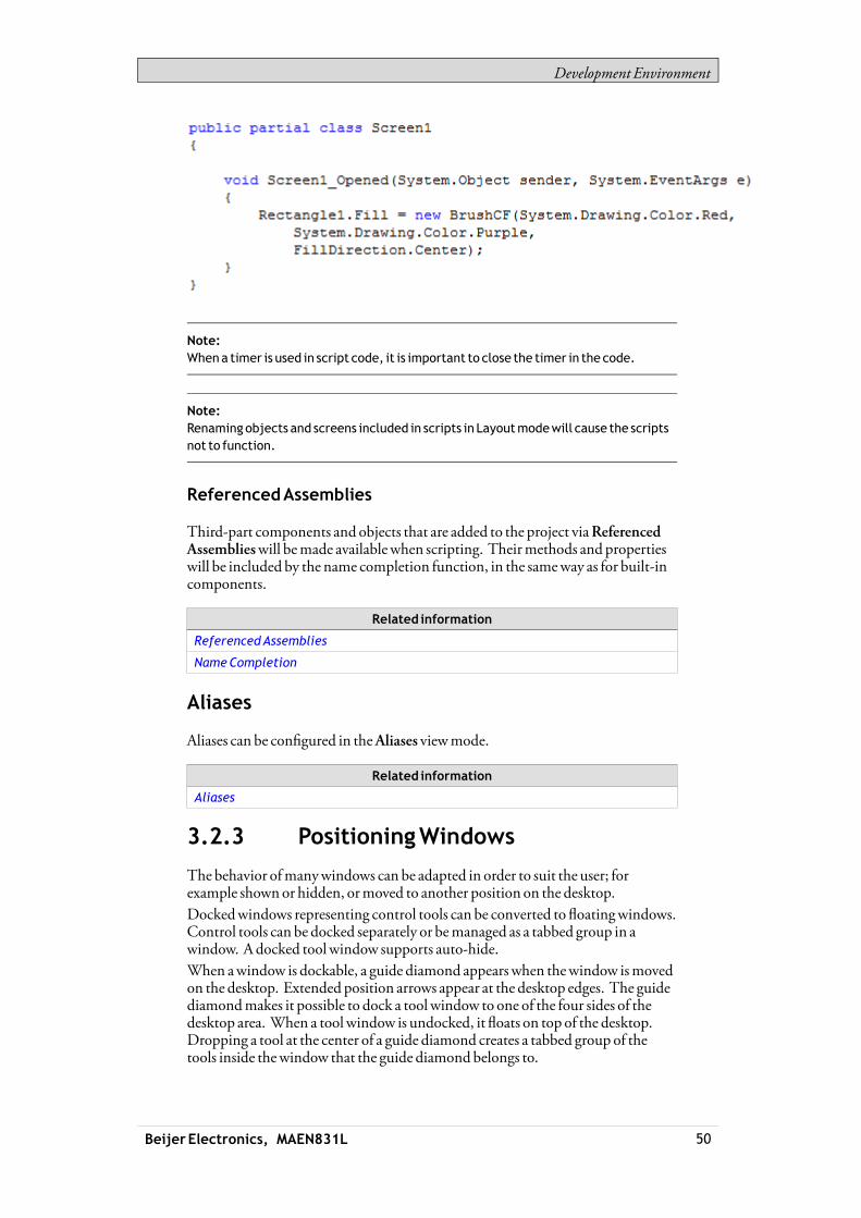
Development Environment
Note:Whena timer is used in script code, it is important to close the timer in the code.
Note:Renamingobjects and screens included in scripts in Layoutmodewill cause the scriptsnot to function.
ReferencedAssemblies
Third-part components and objects that are added to the project viaReferencedAssemblieswill bemade availablewhen scripting. Theirmethods and propertieswill be included by the name completion function, in the sameway as for built-incomponents.
Related information
ReferencedAssemblies
NameCompletion
Aliases
Aliases can be configured in theAliases viewmode.
Related information
Aliases
3.2.3 PositioningWindows
The behavior ofmanywindows can be adapted in order to suit the user; forexample shownor hidden, ormoved to another position on the desktop.Dockedwindows representing control tools can be converted to floatingwindows.Control tools can be docked separately or bemanaged as a tabbed group in awindow. Adocked toolwindow supports auto-hide.When awindow is dockable, a guide diamond appears when thewindow ismovedon the desktop. Extended position arrows appear at the desktop edges. The guidediamondmakes it possible to dock a tool window to one of the four sides of thedesktop area. When a toolwindow is undocked, it floats on top of the desktop.Dropping a tool at the center of a guide diamond creates a tabbed group of thetools inside thewindow that the guide diamondbelongs to.
Beijer Electronics, MAEN831L 50

Development Environment
DockingaTool
Drag thewindowheading to any position on the screen. If the tool is not dockedit will becomefloating.To re-dock a tool:1. If the tool is docked already, double-click on its heading to change to floating.2. Drag the tool to the center of the desktop. A guide diamond appears, pointing
towards the four edges of the desktop. Release thewindow to the desireddirection. When themouse pointer is in position, an outline of thewindowappears in the designated area.
DockingaTabbedGroup
It is possible to dock a tool to an existing group of tools, creating a groupedwindowwith tabs:1. If the tool is docked already, double-click on its heading to change to floating.2. Drag the tool to the center of the existing group. A guide diamond appears.3. Drop the tool at the guide diamond center.
ReleasingaTool fromaTabbedGroup
When awindow containsmultiple tools, they appear as tabs in the lower part ofthewindow. To release a tool that resides in a tabbed group, drag the tab for thetool and drop it on the desktop.
Auto-Hide
Auto-Hide enables amaximized viewof the desktop area byminimizing toolwindows along the edges of the desktop areawhennot in use. Auto-Hide is turnedon and off by clicking theAuto-Hide pushpin icon on thewindow title bar.Toolwindows expand to their original sizewhen the pointer hovers over them.When a hidden toolwindow loses focus, it slides back to its tab on the edge of thedesktop area. While a tool window is hidden, its name and icon are visible on a tabat the edge of the desktop area.
Beijer Electronics, MAEN831L 51
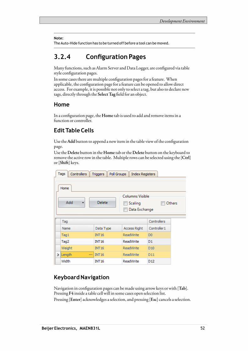
Development Environment
Note:TheAuto-Hide functionhas tobe turnedoff before a tool canbemoved.
3.2.4 ConfigurationPages
Many functions, such asAlarmServer andData Logger, are configured via tablestyle configuration pages.In some cases there aremultiple configuration pages for a feature. Whenapplicable, the configuration page for a feature can be opened to allowdirectaccess. For example, it is possible not only to select a tag, but also to declare newtags, directly through theSelectTagfield for an object.
Home
In a configuration page, theHome tab is used to add and remove items in afunction or controller.
EditTableCells
Use theAddbutton to append a new item in the table viewof the configurationpage.Use theDeletebutton in theHome tab or theDelete button on the keyboard toremove the active row in the table. Multiple rows can be selected using the [Ctrl]or [Shift] keys.
KeyboardNavigation
Navigation in configuration pages can bemade using arrow keys orwith [Tab].PressingF4 inside a table cell will in some cases open selection list.Pressing [Enter] acknowledges a selection, and pressing [Esc] cancels a selection.
Beijer Electronics, MAEN831L 52

Development Environment
Press [Delete] to remove a valuewhen editing in a field. If a row is selectedwhenpressing [Delete], the entire rowwill be removed from the table.Use [Spacebar] to toggle a value in a check box.Press [Ctrl] + [Tab] to shift focus from the table.
Navigation inLayeredPages
A layered configuration page (for example the alarm items page) has some specificnavigation functions.Keyboard navigation down ismade by pressing [Ctrl] + [DownArrow]. This willnavigate into an expanded group, and out againwhen at the last of the expandedrows.Keyboard navigation up and out of a group is done by pressing [UpArrow].Expand a groupwith [Ctrl] + [+], collapsewith [Ctrl] + [-].Keyboard navigation betweenfields inside a group ismadewith [RightArrow]or [Left Arrow].Pressing [Enter] acknowledges a selection, and pressing [Esc] cancels a selection.
AutoFill
Fields in the configuration tables arewhenpossible automatically filled inwhen[DownArrow] is pressedwhen at the last table row. Whenneeded, names andtag identifiers are incremented to avoid exact copies of symbolic names and tagidentifiers. Incrementing is done if the last part of the string is an integer number.A “1”will be appended to the string if no numeral character ends the string. This isuseful when there are consecutive tags of the same type in the controller data.
Filtering Items
Items in configuration pages can be filtered by selectingShowSelection from theShowSelection/ShowAll button.
Clicking the button opens the Filter Builder.
Beijer Electronics, MAEN831L 53

Development Environment
Several conditions can be used, and the different values/operators that can be usedformaking conditions are displayedwhen clicking on the condition buildingblocks.Operands and operator nodes are context sensitive. Name strings are not casesensitive. Values in the filter builder are saved individually for each functionduring an edit session. A filter is built as a logical expression tree. A filter typicallyhas operations on individual column values as leaf nodes and logical operatorsserve asmain nodes.The following color scheme is used:
Color Function
Red Logical operator
Blue Columnoperand
Green Valueoperator
Grey Valueoperand
An indication that a filter is used is displayed at the lower part of the configurationpage.
Selecting ShowAll from the ShowSelection/ShowAllbutton in theconfiguration page displays the complete, unfiltered list.
3.3 Screens
Screens contain objects that can be displayed for the operator in runtime. Ascreen can contain predefined objects, such as buttons or an alarm list. Pictures ofphysical objects, such a pump, connected to controller data, can also be includedto be used for control andmonitoring of the physical object.Properties are defined for each screen.Screens are edited in the desktop area and can bemanaged from:
Beijer Electronics, MAEN831L 54

Development Environment
Location Used for
TheNavigationManager
Adding newscreens,managing links between screens,deleting screens
TheScreens list in theProject Explorer
Adding newscreens, importing screens fromotherprojects, renaming screens, setting screenas startupscreen, saving screens as templates, deleting screens,editing screen scripts
The Screengroupof theHome ribbon tab
Addingnewscreens, selectionof screen templateandbackground screen,deleting screens, language selection,screen security
TheScreengroupof theGeneral ribbon tab
Managingpopup screenproperties and selecting screensfor preloading
3.3.1 ScreenNameandScreenTitle
All screens have unique names, visible e.g. in the Project Explorer and theNavigationManager. Names of all open screens are shown as tabs in the desktoparea. The name of the current screen is displayed and can be changed in theNamegroup of theHome tab.In runtime, the screen name is displayed togetherwith the project title in the titlebar as default. Todisplay something other than the screenname, a screen titlemaybe added in the Screen group on theGeneral tabwhen the screen is selected.
Note:The screenname in iXDeveloper is not updatedwhen the screen title (for display inruntime) is renamed.
If the project title on the Project tab is left empty, only the screenname or screentitle is displayed.
3.3.2 BackgroundScreen
It is possible to use another screen as background screen, to, for example, create auniformdesign of the screens in the project and avoid repetitive configuration.Background screens belong to the current project.
Beijer Electronics, MAEN831L 55
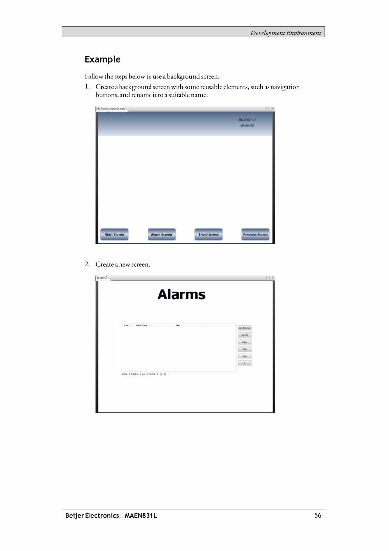
Development Environment
Example
Follow the steps below to use a background screen:1. Create a background screenwith some reusable elements, such as navigation
buttons, and rename it to a suitable name.
2. Create a new screen.
Beijer Electronics, MAEN831L 56

Development Environment
3. Keep the new screen open on the desktop, and select the background screenfrom theScreen group of theHome ribbon tab.
The background screen is nowused for the screen.Anymodificationmade to the background screenwill be reflected in all screensusing it.
3.3.3 StartupScreen
The startup screen is the first screen that openswhen a project is executed. Bydefault, Screen1 is set as startup screen.Another startup screen can be set at any time by right-clicking on the screen on thedesktop or in the Project Explorer and selectingSet as Startup Screen.The selected startup screen is easily distinguished from the other screens in theProject Explorer by a blue outlinewhen in focus.
3.3.4 ScreenTemplate
The installation of iXDeveloper includes a number of screen templates with basicfunctionality. It is also possible to save your own screens as screen templates, byright-clicking on the current screen and selecting Save Screen asTemplate.The screen template can be used in the current or other iXDeveloper projects.If a selected screen template contains tags thatwere not previously included in theproject, you can select to automatically add these to theTags list.To use a template screen, click the lower part of theAdd Screen button in theScreen group of theHome ribbon tab. Apreview of screen templates is displayed.User-created aswell as predefined screen templatesmay be deleted byright-clicking on the template in the preview and selectingDelete ScreenTemplate. The folder of the selected screen is then permanently deleted fromdisk.
Beijer Electronics, MAEN831L 57

Development Environment
3.3.5 ScreenSecurity
Using security settings for screensmakes it possible to restrict access to screensbased onuser security groups, similarly to object security.It is not possible to set security for the Startup screen.Whenusing a background screen, the security settings of the top level screen areapplied.When screens are imported fromother iXDeveloper projects or fromInformationDesigner, security settings are included andwill be used in thecurrent project.
Related information
Object Security andVisibility
3.3.6 PopupScreen
Normally, only one screen is visible in the operator panel in runtime. Sometimes, apopup screen that behaves like as a floatingwindowmaybe useful. Any screen canbe configured as a popup screen:1. CheckPopup screen in the Screen group of theGeneral tab.2. Set the start position coordinates (X, Y) to determinewhere the screenwill
open. The position (1,1) corresponds to the upper left corner of the screen.3. Set the desiredwidth and height in pixels of the screen resolution.ClickingModify Screen Size/Position allows changing the popup screensize and position by dragging itwith the cursor. The coordinates are updatedautomatically.
Modal PopupScreen
Checking theModal optionmakes the selected popup screenmodal, whichmeansthat the user cannot interact with other screenswhile this screen is visible. Allother screenswill still be updated.
Note:It is not recommended tohavemore than twoparallelmodal popup screens openatthe same time.
Note:Donot usemultiplemodal popups triggeredbybackgroundevents such as alarms, tagvalue changes, etc.
Style
Different styles can be selected for popup screens for PC targets.
Beijer Electronics, MAEN831L 58

Development Environment
Note:Whenusing awebbrowser or pdf viewer object in apopup screen, only thedefault stylefor thepopup screen is supported.
OpenPopupScreen
Apopup screen is opened in runtime by a ShowScreen action on an object.
Note:Whenconfiguring a ShowScreenaction for a popup screen,positionof the screencanbe selected. These settings override the settingsmade in the Screengroupof theGeneral tab.
ClosePopupScreen
Apopup screen is closed in runtime by aClose Screen action on an object.If theClose Screen action is triggered from a tag, this will close both the popupscreen and the parent screen.
3.3.7 Preloading Screens
Thefirst time a screen is opened in a running project, some time elapses whilecompiling it. In order tominimize this time, it is possible to preload amaximumof 10 screens from theScreen group on theGeneral tabwhile the screen is selected.The selected screenswill then be loaded at application startup instead ofwhenopening the screen.
Note:The time savedat screenopening is insteadadded to theapplication startup time.
Events related to screen actions (ScreenOpened, ScreenClosed and ScreenClosing)will not be carried outwhen a screen is preloaded.Preloading the startup screen (or its background screen) has no effect. Popupscreens cannot be preloaded.The preload function is available for operator panel targets only.
3.3.8 Importing Screens
Screens fromother projects can be imported, by right-clicking in Screens area ofthe Project Explorer and selecting Import.If the selected screen has a name identical to one of the existing screens, a newscreen name is proposed.If the imported screen includes tags that do not already exist in projects, you areasked if youwant to add these.
Beijer Electronics, MAEN831L 59

Development Environment
Note:No tag information, other than tagnames,will beaddedby the import function.
3.3.9 Grid
There are differentmethods to align objects in screens; Snap objects to otherobjects and Snap objects to grid. Grid properties aremanaged by right-clickingon the current screen and selectingGrid from the contextmenu. It is also possibleto select not to snap objects.Grid settings are global andwill affect all screens.
SnapObjects toOtherObjects
Tohelp position objects in a screen snap lineswill appearwhen an object ismovedacross the screen. The snap lines are used to align the dragged object with otherobjects on the screen.Blue snap lines appearwhenever the right, left, top, or bottomboundaries coincidewith other object boundaries. A horizontal red snap line indicates that the centerof the object is alignedwith the center of another object. For vertical centeralignment, select the objects and useAlignCenter in theArrange control of theFormat group.
SnapObjects toGrid
Use the contextmenu and select Snap toGrid to enable binding to grid points for amoved object. Snap toGridmode disables SnapLines for dragged objects.
Grid
The different grid styles can be used as a help patternwhen doing the layout of theobjects on the screen.
Grid setting Description
Spacing Number of pixels betweengrid lines
Showgrid on screen Displays the grid on the screen
Grid style Selectionbetweendots and lines as grid style
Beijer Electronics, MAEN831L 60

Development Environment
3.4 Objects
Objects that can be created in a screen are available from theObjects group andtheComponent Library.Snap lines are used to position objects in a screen and align amoved object withother objects.Information about tag connections aswell as size and distance information forobjects on the current screen can be displayed by using the buttons in the lowerpart of the desktop area.
Related information
Objects
3.4.1 HandlingObjects
Create
To insert a default-sized object, click the position on the screenwhere youwant toplace the object.To give the object a specific size and shape, press themouse button and drag tocreate the object on the screen. Press andhold [Shift] while creating an object toretain the aspect ratio of the object.When creating a line object, press and hold [Shift] to constrain the line at 45degrees angles.
Select
TheSelect tool is available at top left in theObjects groupwhen the group is notexpanded. The Select tool is the default toolwhen editing screens. After applyingany other object control, themouse pointer will return to the Select tool. Whenthe Select tool hovers over a selected object themouse pointer changes to a crosswith arrowheads.
Move
The position of an object is part of the properties for the object. The position of anobject can be changed in differentways:• Click and drag an object tomove it to the desired position.• Open the property grid and edit theLeft andTop coordinates.Tomove the selected object one pixel at the time, select the object and use thearrow keys on the keyboard.
CopyandMove
Use [Ctrl] + drag tomake a copy of the selected object, and tomove it to thedesired position.
Beijer Electronics, MAEN831L 61
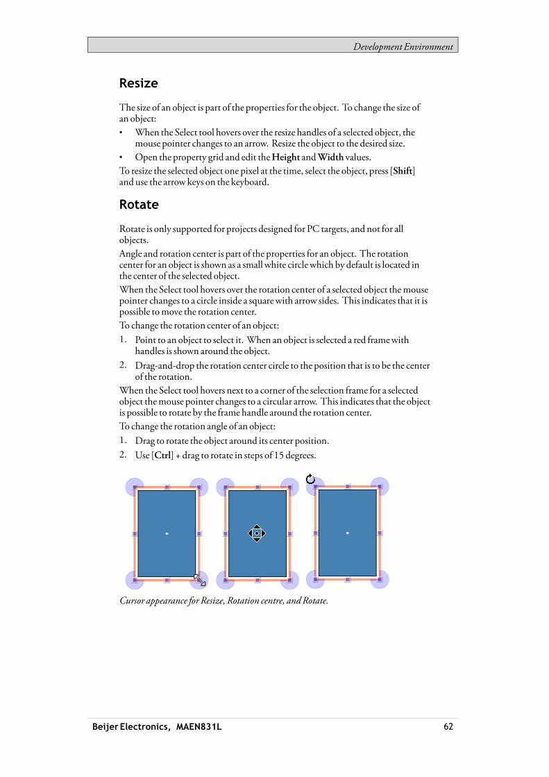
Development Environment
Resize
The size of an object is part of the properties for the object. To change the size ofan object:• When the Select tool hovers over the resize handles of a selected object, the
mouse pointer changes to an arrow. Resize the object to the desired size.• Open the property grid and edit theHeight andWidth values.To resize the selected object one pixel at the time, select the object, press [Shift]and use the arrow keys on the keyboard.
Rotate
Rotate is only supported for projects designed for PC targets, and not for allobjects.Angle and rotation center is part of the properties for an object. The rotationcenter for an object is shown as a small white circlewhich by default is located inthe center of the selected object.When the Select tool hovers over the rotation center of a selected object themousepointer changes to a circle inside a squarewith arrow sides. This indicates that it ispossible tomove the rotation center.To change the rotation center of an object:1. Point to an object to select it. When an object is selected a red framewith
handles is shown around the object.2. Drag-and-drop the rotation center circle to the position that is to be the center
of the rotation.When the Select tool hovers next to a corner of the selection frame for a selectedobject themouse pointer changes to a circular arrow. This indicates that the objectis possible to rotate by the frame handle around the rotation center.To change the rotation angle of an object:1. Drag to rotate the object around its center position.2. Use [Ctrl] + drag to rotate in steps of 15 degrees.
Cursor appearance for Resize, Rotation centre, andRotate.
Beijer Electronics, MAEN831L 62

Development Environment
SelectingMultipleObjects
Multiple objects on the current screen can be selected at the same time, with theuse of themouse pointer to draw a frame that touches the objects. Alternatively,select one object and thenuse [Ctrl] + click to select or de-select other objects.Amultiple selection can be used to arrange objects, by using theArrange controlon the Format ribbon tab. The object with the primary selection is used as guideobject.Whenmultiple objects are selected, the primary selection is shownwith a redframe,while all other objects in the grouphave blue frames.Click on any object in the group to change this to the primary selection. A click ordouble-click on any objectwillmake it the primary selection, and, if applicable,change the ribbon focus according to the selected ribbon behavior.The groups shown in theGeneral and theActions tabs are dependent on theselection. Whenmultiple objects are selected the tabswill showonly the propertiesthat are common for the objects in the selection. Property changeswill affect allselected objects.
HidingandLockingObjects
Objects can easily be hidden and locked using theObject Browser, but thecommands are also available from the contextmenu. Tomake a hidden objectvisible again, or to unlock a locked object, theObject Browser can be used.
Related information
ObjectBrowser
PropertyGrid
Creating Series
TheCreate series function facilitates creating a number of identical objects. Thefunction handles adding graphic elements aswell as controller connections.The following example creates a series of analog numeric objects quickly andeasily:1. Create an analog numeric object and connect it to a tag (in this example;D0).2. Right-click on the object and selectCreate series from the contextmenu.
Beijer Electronics, MAEN831L 63

Development Environment
3. Fill in the number of objects to add andmake settings for the addressincrementation, and clickOK.
Parameter Description
Number of copies Enter thenumberof columns and rows to create
Spacing Specify thenumber of pixels between the addedobjects
Addressincrementation
Select how to increment addresses for theaddedobjects.Only addresses available in thedriverwill be added.
Incrementdirection Select if addresses are tobe incremented inhorizontal orvertical direction
Graphical objects are added on the screen according to the settingsmade:
Tags are added to the project according to the settingsmade:
Beijer Electronics, MAEN831L 64

Development Environment
Right-clicking in theTags configuration page and selectingCreate seriesmakes itpossible to create a series of tags quickly and easily, without adding graphic objects.
3.5 NavigationManager
TheNavigationManager is used tomanage screens and their relationswith respectto project navigation in runtime. It can be activated/deactivated from theViewtab. It provides an overview of all screens in the current project.
Beijer Electronics, MAEN831L 65

Development Environment
3.5.1 ScreenRelations
TheNavigationManager is used to create relationships between screens.Dragging themouse pointer fromone screen to another screen creates a relation. Abuttonwith aClick action is defined in the first screen. This ShowScreen actionhas the second screen as target, andwhen clicking it in runtime, the second screenis opened.Double-click on a screen to open the screen for editing in the desktop area.
3.5.2 AddScreen
New screens can be added directly in theNavigationManager.Dragging themouse pointer from an existing screen to an empty location in theNavigationManager area creates a new screen,with a relation to the originalscreen. A buttonwith aClick action is defined in the first screen. ThisShowScreen action has the second screen as target, andwhen clicking it in runtime, thesecond screen is opened. The buttonmust be removed or changedmanually ifthe new screen is deleted later.
3.5.3 Links in theNavigationManager
A structure of screens and their relations to other screenswill be imposed andshown in theNavigationManager. TheNavigationManagerwill provide anoverview to help add screens andmanage the link relations between projectscreens.
Beijer Electronics, MAEN831L 66

Development Environment
Right-click anywhere in theNavigationManager to change link appearance.
Link setting Description
ShowSameLevelReferences
Filters out links to screens on the samehierarchical level.
ShowBackReferences Showsnavigation links to higher hierarchical levels. Whennot selected, only links to screens on lower levels andlinks between screens on the same level are shown.
DirectedLinks Draws straight link lines between screens, using theshortestway.
Orthogonal Links Draws link lines in anorthogonal pattern.
Changing the setting or the type affects the appearance in theNavigationManageronly.
3.5.4 NavigationOverview
It is also possible to display theNavigationOverview by selecting it from theViewribbon tab. It provides an overviewof all screens included in the project, withzooming facilities.
3.6 ProjectExplorer
TheProject Explorer shows all screens and components included in theapplication. It can be activated/deactivated from theView tab.The Project Explorer is divided into five groups; . Screens,Functions,DataLoggers,ScriptModules andRecipes.
Beijer Electronics, MAEN831L 67

Development Environment
3.6.1 ProjectExplorerGroups
Click on the groupheading to expand/collapse the groups. The number ofcomponents in each folder is apparent from the groupheadings. Right-clicking ona group opens a subset of the commands from theFilemenu and Insert tab.Right-clicking on a component in a Project Explorer group opens a contextmenuwith a selection of commonoperations. Not all commands are available for allcomponents.
Beijer Electronics, MAEN831L 68
Development Environment
Contextmenucommand
Description
Show Opens the selectedproject component for editing in thedesktoparea
Rename Renames the selectedproject component
Add Adds anewproject component to theproject
Import Imports aproject component via browsing theharddisk; e.g. ascreen fromanother project
Delete Deletes the selected component fromtheproject
Screens
TheScreens explorer lists the screens included in the application. Clicking on ascreen opens it for editing in the desktop area.
ScreenContextMenu
Right-clicking a screen opens a contextmenuwith a selection of availableoperations:• Show• Rename• Import• Delete• Set as startup screen• Save screen as template screen• Add to screen group• Remove from screen group
The screen set to be the startup screen ismarkedwith a green frame in the screensexplorer.
Groups
TheScreens explorer offers a possibility to assign screens to groups.• Right-click on theAll screensheading in theScreens explorer and selectAdd
group followedby entering a unique name for the group in the appearingdialog.
• To assign a screen to a group, simply right-click a screen in the Screensexplorer and select “Add to ScreenGroup” from the contextmenu. Select agroup to add the screen to from the appearing “Select Screen group” dialog.
• To show available groups, double-click theAll screensheading in the Screensexplorer. Screens not assigned to a groupwill be listed asungrouped screens.
• Right-clicking a group enables a contextmenu fromwhich you can choose torename or delete the group.
Note:Deleting a Screen groupalso deletes all of its assigned screens.
Beijer Electronics, MAEN831L 69

Development Environment
It is also possible to assign a screen to a group by a simple drag and drop operation.Drag the screen symbol and release it on the group.
ZoomSlider
TheZoom slider is found in theScreens explorer and provides away to quicklyzoom in andout of your screens explorer.
Search
The search function provides the option to search for screens using the screenname or screen-id.The search is only performedwithin the selected group.
Functions
TheAlarmServer,Multiple Languages and Security functions are predefined, aswell as Tags, and cannot be deleted from the Functions folder. The other functionscan be added from the Insertmenu. Most functionswill be available from theFunctions folder after having added them to the project, but some functions areassigned folders of their own.Clicking on the function in the Functions folder opens its configuration pagesfor editing in the desktop area.
AlarmDistributor
Alarms can be distributed between operator panels, with notification via printer,SMSor e-mail using the alarmdistributor.
Related information
AlarmDistributor
AlarmServer
TheAlarmServer handles alarm groups and alarm items.
Related information
AlarmServer
AlarmGroups
Alarm Items
AuditTrail
TheAudit Trail function enables tracking of operator actions.
Related information
Audit Trail
Beijer Electronics, MAEN831L 70

Development Environment
FunctionKeys
Function keys for operator panels as well as for the regular PCkeyboard can beconfigured.
Related information
FunctionKeys
MultipleLanguages
Configuringmultiple languages for user texts and system texts are supported. Thetexts can be exported, edited and reimported to the project. A tool for automatictranslations is also included.
Related information
LanguageManagement
Reports
The reports function allows adding excel report templates to the project.
Related information
Reports
Scheduler
A scheduler can be used to control events in the process at special times.
Related information
Scheduler
Security
Users and groups of users can be set up for security purposes.
Related information
SecurityManagement
Tags
Clicking onTags in the Functions folder displays the tags configuration page inthe desktopwith all the tags that are used in the application. Tags are added byclicking on theAddTag/Add SystemTag button.Tags can belong to a connected controller, or be internal. Internal tags can be usedand selected in the sameway as a regular controller tags.System tags are used tomonitor or access variables from the system, for exampleUsedRAM orDateTime. System tags are indicated by blue color in the tag list.
Beijer Electronics, MAEN831L 71

Development Environment
Related information
Tags
InternalTags
SystemTags
TextLibrary
With the text library function, text tables can be created,where values are linkedto texts.
Related information
Text Library
Recipes
Several recipes can be inserted in the project. Each recipe function handles apre-defined set of recipe items.
Related information
RecipeManagement
ScriptModules
Clicking on a scriptmodule in the ScriptModules folder opens the script editorin the desktop area. A scriptmodule can be included to program features notcovered by included functions and actions, or to be used to share functionalityamong functions.There is also a script action function that can be used to apply scriptmodules to anobject in the sameway aswith other trigger actions.
Related information
Script
ScriptAction
DataLoggers
Data can be logged and saved to a database on time intervals or depending onchanged values.
Related information
Data Logger
3.7 ComponentLibrary
TheComponent Library contains reusable components for a project.
Beijer Electronics, MAEN831L 72

Development Environment
3.7.1 Components
TheComponent Library includes a large number of predefined graphical objects,categorized into groups. User-defined graphical objects and other filesmay also besaved in the component library. All components in a sub foldermust have uniquenames.Examples of components thatmay be included in the library:• predefined components• objects• text objects configuredwithmultiple texts• symbol objects configuredwithmultiple symbols• grouped objects• external pictures• text• folders (file folders)• HTM/HTMLfiles• media files• PDFfiles
Since plain text can be saved as a component, it is possible to save reusable scriptcomponents by dragging a section of script code from the Script view into theComponent Library.A component is displayedwith its name and a thumbnail representation in theComponent Librarywindow.Grouped objects are displayed as a thumbnail representing the primaryselection of the object. Text files and folders are represented by operating systemthumbnails.
Note:Only static graphical objects are supported in iXDeveloper.
ProjectPictures
TheProject Pictures folder is project specific, and contains pictures that are used inthe current project. The components in Project Pictures are stored in the project’sSymbols folder.
ProjectFiles
TheProject Files folder is project specific, and contains files that have been addedwhen creating the project.Project files and folders can be added and deleted from the Project Files folderbefore downloading the project to an operator panel. The Project Files folderis located in the Project folder.For instance, “C:\MyProjects\ProjectFolder\Project Files”.It is also possible to access the operator panel via FTP to add and delete files andfolders after the download, provided that the FTP service is enabled in the project.
Beijer Electronics, MAEN831L 73

Development Environment
Related information
FTP
Download
3.7.2 AddandUseComponents
Drag-and-drop any component from the library to the current screen, or use copy[Ctrl +C] and paste [Ctrl +V] commands.Objects can be copied ormoved to theComponent Library.A text file, that is saved in theComponent Librarywill be converted to a text boxobject when pasted into a screen.A component (picture or group) that is originally copied from an object with a tagconnectionwill keep its tag connection and any dynamic propertieswhen usedfrom theComponent Library.
Note:If a componentwith a tag association is reused in another project then all referencedtagsmust bepresent in thenewproject.
3.7.3 ComponentLibraryWindow
The component library is available as a tab at the right-hand side of thedesktop. Thewindow is configuredwith auto-hide functions, and can also beactivated/deactivated from theView ribbon tab. Its appearance can bemanagedjust as other tools; as docked or floatingwindows.TheComponent Library is also accessible when selecting andplacing the Pictureobject from theHome ribbon tab.
Beijer Electronics, MAEN831L 74
Development Environment
User-DefinedCategories
Right-click on an empty space of theComponent Librarywindow and selectAddComponent to add a component to the library. To create a new category, selectAddCategory and choose a name of your preference. A category could also berenamed or deleted.User-defined categories are not project specific. Thismeans that all objects savedin a user-defined categorywill be available in all iXDeveloper projects.
Exportingand ImportingComponents
Byusing the Import andExport functions in theComponent Library, categoriesof components can easily be copied andmoved between projects. Right-click onthe category folder and select Import orExport. Find the location in the projectfile fromwhere the components should be imported or towhere they should beexported. The programwill not indicatewhere the component files are located.Single objects can not be exported or imported.
ExpandandCollapseFolders
The top area is a contents frame that is used to navigate through the folders of theComponent Library. The contents heading displays the name of the currentlyselected folder. The folder view can be expanded and collapsedwith the control tothe left of the displayed folder name.The display of the components is filtered through the selection of the folders, i.e.all components are displayed if the top folder is selected.
Search
TheSearch feature provides a case-insensitive and alphabetical search, based onthe component label, in the current folder and in all sub folders.
Zoom
TheZoom slider at the bottom area of the tool window can be used to change thesize of the displayed components. Resting themouse pointer over a componentdisplays a full-size picture of the component.
Beijer Electronics, MAEN831L 75

Development Environment
Component Librarywindow, displaying full size of a selected component
XAMLGuidelines
All information, including the image,must be containedwithin theXAML-file.Links to external objects will result inmissing objects. Furthermore, theappearance of theXAML-filemay not be dependent of external inputs, like forexample a parameter controlling amulti-picture based on internal logicwithin theXAML-file.The following restrictions apply:
DoNotNameControls inXAML
Not supported:
Beijer Electronics, MAEN831L 76

Development Environment
Supported:
SpecifyWidthandHeight
The root controlmust specify awidth and a height.Not supported:
Supported:
Beijer Electronics, MAEN831L 77

Development Environment
Bindings
These are the only properties that are supported forXAML-bindingwithincomponents:• ISymbolViewboxSignature.Fill is presented as “Fill”within the property grid• ISymbolViewboxSignature.Stroke is presented as “Outline”within the
property grid• ISymbolViewboxSignature.StrokeThickness is presented as
“OutlineThickness”within the property grid
It is not supported to bind to anything outside of the component.Supported:
Beijer Electronics, MAEN831L 78

Development Environment
3.8 PropertyGridMost properties and settings for anobject or screenaredefined from itsGeneral andHome tabs.
Adetailedoverviewof object propertiesis availableby selectingPropertyGridfrom theView ribbon tabor by selectingProperties from thecontextmenu.
Theproperty grid includesmoreproperties and settings than the ribbontabs, for example size andpositionofobjects, anddelayofmouseand touchscreen input in runtime.
Property groups canbecollapsed/ex-panded.
Thewindow is configuredwithauto-hidefunctions. Its appearancecanbemanaged just as other tools; as dockedorfloatingwindows.
3.8.1 Search
The Search feature provides a case-insensitive and alphabetical search, thatmakesit easy to reduce the number of displayed properties.
3.8.2 Toggling views
The different views in the Property grid can be selected by using themenuon thetop of thewindow.
Beijer Electronics, MAEN831L 79

Development Environment
Showonly thepropertiesmarkedas favorites
Showall properties in thePropertyGrid
Showall properties that donot have their default value
Selectwhether Favorites are editable ornot
Showor hide theCopyProperties functions in thePropertyGrid
3.8.3 Favorites
The propertiesmost commonly used can be added to a Favorites-category foreasier access. The favorites are saved per object type, i.e. Button has one set offavorites, AnalogNumeric has one set of favorites, Chart has one set and so on.
Ayellow star indicates that theproperty is addedas a favorite. By clicking thestar, theproperty is deselectedand removed fromtheFavorites-category
Whenclicking ona greyedout star, the correspondingproperty is added to theFavorites-category
3.8.4 CopyProperties
Multipleproperties canbecopied fromoneobject to oneormore targets.Theproperties canbe selectedeither onebyonebyclicking the checkboxnext to eachproperty, or all at onceby clicking thebutton for Select all,followedbyaclick on theCopyPropertiesbutton. Thevalues are thenpastedonto the target object(s)when selecting the target(s) and clickingonPaste.
Note:Only theproperties that are sharedbyboth sourceand target objects are transferred.
Selects all properties for theobject
Deselects all properties for theobject
Copies the selectedproperties to the clipboard
ClickingPastepastes the copiedpropertiesonto the selectedobject(s)
Beijer Electronics, MAEN831L 80

Development Environment
3.9 ObjectBrowser
Anoverviewof all objects included in a screen can be displayed in theObjectBrowser.
It is easy to bring objects thatmay have been obscured by other objects up front, byusing the arrows at the top left.Clicking the buttons at the right side of each object enables simply hiding/showingand locking/unlocking objects.Note that the top-to-bottomorder in theObject browser corresponds to thefront-to-back order on the screen.
3.10 Output
TheOutputwindow containsmessages concerning the project validation andbuild. Created project files with folder paths and any found errors will be listed inOutput.
Note:Incorrect codeentered in textmode (Xamland Script)may result in errors that arenotpossible to recognizeduring analysis andbuild.
3.11 ErrorList
TheError List contains information about problems and errors detected in iXDeveloper for the current project. Build errors are reported in theOutputwindow.
3.12 Help
TheHelp file for iXDeveloper can be opened by pressingF1 on the keyboard orusing theHelp button in the ribbon tab heading.
Beijer Electronics, MAEN831L 81

Tags
4 Tags
Objects connected to tags can change values in a controller, and controller valuescan be reflected by changing object appearance in variousways. Objects in a screenwill remain static until connected to a tag.A tag has a symbolic name and can be of different data types.Tags can belong to a connected controller, be internal or belong to the system.Internal tags are used to handle local data values, and can be viewed and treated inscreens just like regular controller tags.The global tag list provides an overviewof all used tags, regardless of controller.Thismakes it easy to develop projects that can be usedwith a variety of controllers.It is also possible to connect a tag tomore than one controller simultaneously.
4.1 AddingTags
Tags are handled by clicking onTags in the Functions folder in the ProjectExplorer.
Clicking theAddTag/AddSystemTagbutton adds a new tag to the list. Makesettings for each added tag. When predefined values are available, these can beselected by clicking the arrow at the right of the table cell.
4.1.1 RemovingUnusedTags
TheDeletebutton inTags can be used to detect unused tags for immediateremoval via theRemoveUnusedTagsdialog.
Beijer Electronics, MAEN831L 82

Tags
Similarly, when building the project, a notification of any unused tagswillautomatically be done by displaying theRemoveUnusedTagsdialog. To disableor enable pop-up of this dialog, go toOptions in theFilemenu. SelectBuildoptions in the list and then selectCheckForUnusedTagsunderMisc. Change thestatus of the function toTrue orFalse.
Beijer Electronics, MAEN831L 83
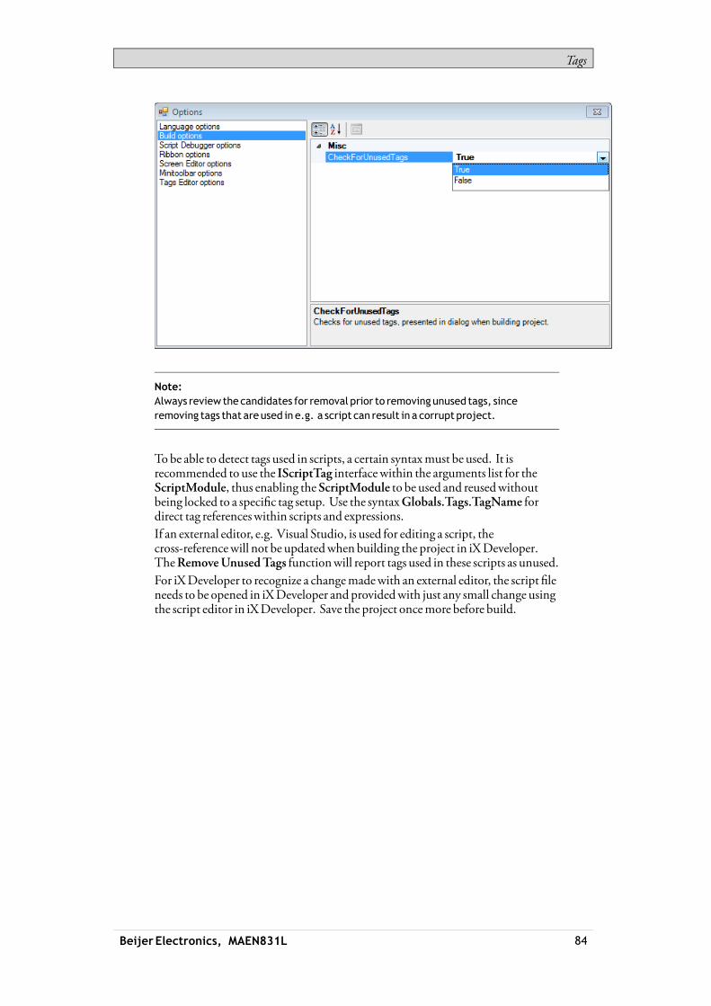
Tags
Note:Always review thecandidates for removal prior to removing unused tags, sinceremoving tags that areused in e.g. a script can result in a corruptproject.
Tobe able to detect tags used in scripts, a certain syntaxmust be used. It isrecommended to use the IScriptTag interfacewithin the arguments list for theScriptModule, thus enabling theScriptModule to be used and reusedwithoutbeing locked to a specific tag setup. Use the syntaxGlobals.Tags.TagName fordirect tag referenceswithin scripts and expressions.If an external editor, e.g. Visual Studio, is used for editing a script, thecross-referencewill not be updatedwhenbuilding the project in iXDeveloper.TheRemoveUnusedTags functionwill report tags used in these scripts as unused.For iXDeveloper to recognize a changemadewith an external editor, the script fileneeds to be opened in iXDeveloper and providedwith just any small change usingthe script editor in iXDeveloper. Save the project oncemore before build.
Beijer Electronics, MAEN831L 84

Tags
TheSummethod inside the script can be utilized inmany different contexts. Thefollowing picture shows howTag3will contain the sumofTag1 andTag2when thebutton is clicked. Notice that the tags used in scriptsmust be activated toworkas expected.
Beijer Electronics, MAEN831L 85
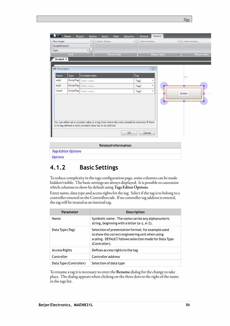
Tags
Related information
Tags EditorOptions
Options
4.1.2 Basic Settings
To reduce complexity in the tags configuration page, some columns can bemadehidden/visible. The basic settings are always displayed. It is possible to customizewhich columns to showbydefault usingTags EditorOptions.Enter name, data type and access rights for the tag. Select if the tag is to belong to acontroller entered on theControllers tab. If no controller tag address is entered,the tagwill be treated as an internal tag.
Parameter Description
Name Symbolic name. Thenamecanbeanyalphanumericstring, beginningwith a letter (a-z, A-Z).
DataType (Tag) Selectionof presentation format; for exampleusedto show thecorrect engineering unitwhenusingscaling. DEFAULT follows selectionmade forDataType(Controller).
AccessRights Defines access rights to the tag
Controller Controller address
DataType (Controller) Selectionof data type
To rename a tag it is necessary to enter theRenamedialog for the change to takeplace. The dialog appearswhen clicking on the three dots to the right of the namein the tags list.
Beijer Electronics, MAEN831L 86

Tags
Related information
Scaling
4.1.3 Scaling
Scaling affects only tags connected to a controller.Checking the Scalingbox displays theOffset andGain columns. Theseparameters are used to change the scale of the controller value to a value shown inaccordancewith the following equation:Panel value =Offset + (Gain×Register value)When the value for an object is changed from the operator panel, the scale ischanged to the value shown in accordancewith the following equation:Register value = (Panel value -Offset)/GainScaling does not affect the definedmaximumandminimumvalues, or the numberof decimals.
4.1.4 DataExchange
Checking theDataExchangebox displays theDirection andWhen columns.Data exchange supports real time data exchange between different controllers; alsoof different brands. The data exchange can be performedwhen a digital tag is set orat a certain time interval, set up on theTriggers tab. Data exchange can be selectedfor individual tags, array tags or for the complete range of tags.
Related information
DataExchange
Beijer Electronics, MAEN831L 87

Tags
4.1.5 Others
Checking theOthers boxmakes it possible to configure a number of additionaltag properties.
Parameter Description
Description Anoptional description of the tag. Descriptionof systemtagsis addedautomatically.
Pleasenote that thedescription cannotbemore than200characters long. Descriptions longer than thatwill causebuilderrors.
Poll Group Makes it possible topoll groups of tags at different intervals.
AlwaysActive Prevents the tag frombecoming inactive. Thismaybeuseful foractions and scripting purposes. Note: TheActive setting for thecontroller on theControllers tab is predominant over theAlwaysActive setting for aparticular tag.
NonVolatile Keeps the last tag value inmemory evenwhen thepanel or PC ispoweredoff. Only available for internal tags.
Initial Value Makes it possible to assign a tag an initial value at systemstartup. Only available for internal tags.
IndexRegister Makes it possible to select a register fromwhichanobject is tocollect the shownvalue.
Action Makes it possible to configureactions basedonaconditionof atag.
Log toAudit Trail Logs operator actions on the tag. Only available if theAudit Trailfunction is activated in theproject.
Audit TrailDescription
Optional static or dynamicdescriptions for operator tagactions, that are saved in theAudit Trail databaseandvisiblein theAudit Trail Viewer. IfDynamicDescription is selected,valuebefore change canbe included in thedescriptionbyusing{0}; value after changebyusing {1}. Only available if theAuditTrail function is activated in theproject.
Beijer Electronics, MAEN831L 88
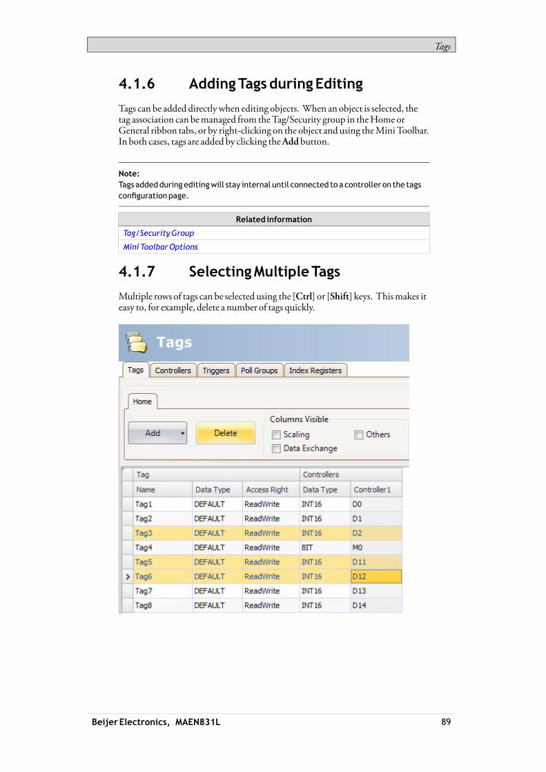
Tags
4.1.6 AddingTagsduringEditing
Tags can be added directlywhen editing objects. When an object is selected, thetag association can bemanaged from theTag/Security group in theHomeorGeneral ribbon tabs, or by right-clicking on the object and using theMiniToolbar.In both cases, tags are added by clicking theAdd button.
Note:Tags addedduring editingwill stay internal until connected to a controller on the tagsconfigurationpage.
Related information
Tag/SecurityGroup
Mini ToolbarOptions
4.1.7 SelectingMultipleTags
Multiple rows of tags can be selected using the [Ctrl] or [Shift] keys. Thismakes iteasy to, for example, delete a number of tags quickly.
Beijer Electronics, MAEN831L 89

Tags
4.2 TagActions
Oneormultiple actions can be configured depending on a changed value of atag. TheAction column is displayedwhen theOthers box is checked in theTagsconfiguration page.Clicking ... in the Actions column for the selected tag brings up theActionproperties window. First, a condition is configured by clickingAddunderCondition. Select a condition, enter a value (only integers are allowed) and clickOK.
Then, configure actions to be executedwhen the condition ismet.
Related information
ActionsRibbonTab
4.3 InternalTags
Internal tags can be used to calculate values that need not be represented in thecontroller, for example information only for the operator. Internal tags are selectedin the sameway as an external controller tags. Any number of volatile user definedtags can be created.
Beijer Electronics, MAEN831L 90

Tags
Note:Internal tag valueswill not be saved in theoperator panelwhen theproject isrestarted, unless theNonVolatileoption is used.
Unlike the regular drivers, it does notmatter if internal tags are used in consecutiveorder or not.
4.4 SystemTags
System tags are used tomonitor or access variables from the system. System tagsare handled as regular controller tags, i.e. can be used in screens, logged, includedin scripts etc. TheDate andTime system tags can be usedwhen youwant to usethe controller clock in the panel project. The following system tags are available:
Systemtaggroup
Systemtag Description
Communication ErrorMessage
Latest communicationerrormessage
Communication Errors Numberof active communicationerrors onall controllers
Communi-cation
RemoteAlarmServerConnection Errors
Numberof remote alarm serverswithconnection errors, e.g. disconnectedservers.
DateTime Current dateand time
Day Daycomponent of current date
DayofWeek Dayof currentweek (1-7where1 is Sunday)
Hour Hour component of current time
Minute Minute component of current time
Month Month component of current date
Second Secondcomponent of current time
DateandTime
Year Year component of current date
Current Screen Id The ID of the current screen.
Thedata typeof this tag is int16and it onlyhas readaccess. This tag gets updatedeverytimeyouopena screen,with theexceptiononpopup screens. Whenopeningapopupscreen thecurrent screen id tagwill not beupdated. Whenentering a screenwithout ascreen id the tag valueof the current screenidwill be set to -1. Note that 0 is a validscreen id.
Current ScreenName Nameof the current screen
Latest LoadedRecipe Nameof the latest loaded recipe
Project
NewScreen Id The ID of the newscreen.
Thedata typeof this tag is int16and it hasread/write access. The tag is always active.
Beijer Electronics, MAEN831L 91

Tags
Systemtaggroup
Systemtag Description
When thenewscreen id tag changes valuea screen jump ismade to the screenwithcorresponding screen id. If no such screenexists a notificationmessagewill show.
If thenewscreencontains configuredscreen instances (alias), thedefaultinstance is always displayed.
ProjectName Nameof the current project
RuntimeVersion Runtimeversionof framework
ScreenUpdateTime Screenupdate time (inms)
AvailableRAM Amountof available RAMmemory (in kB)
Available Storage Amountof available storagememory (inMB)
Backlight BrightnessLevel
Backlight brightness level (in percent)
Whenapproaching 0%backlight, changesinbrightness levelmayno longerbenoticeable in thepanel.
Completedimming (to 0%) is only possible toachievewith themarinepanel types, suchas iXT7AMand iX T15BM.
CPULoad Amountof usedCPUcapacity (in percent)
CurrentUser Theuser nameof the currently logged inuser
Debug LoggingEnabled
Indicates if debug logging is enabled.
Internal Temperature(1)
Internal panel temperature (in °C)
Physical RAM RAMmemory installed (in kB)
Power LEDBlinkFrequency
Blink frequencyof thepower LED (1–10Hz,0 =always on)
Power LEDBlueIntensity
Intensity of thebluepowerLED (0–100)
Power LEDRedIntensity
Intensity of the redpower LED (0–100)
StorageMemory Storagememory installed in computer (inMB)
UsedRAM Amountof usedRAMmemory (in kB)
UsedRAMPercent Amountof usedRAMmemory (in percent ofphysical)
Used Storage Amountof used storagememory (inMB)
Used StoragePercent Amountof used storagememory (in percentof all storage)
System
Beijer Electronics, MAEN831L 92

Tags
Systemtaggroup
Systemtag Description
WindowsCE ImageVersion
WindowsCE ImageVersion
(1) Not applicable on iXTxAand iXTxC.
System tags are indicated by blue color in the tag list.System tags are added by clicking theAddTag/AddSystemTag button in the tagsconfiguration page.
4.5 ArrayTags
An array tag is a tag containingmultiple values.If the array size is >1, the tag is considered as an array tag.
Note:Array tags are only supportedby controllerswhichuseaddresses that canbenumerically increased.
4.5.1 ArrayTagSetUp
Clicking theAdd button adds a tag to the list. Make settings for each added tag.When predefined values are available, these can be selected by clicking the arrow atthe right of the table cell.Clicking theDataType cell in theController columnbrings up the data typeconfiguration page. An array tag is configured by setting the array size to a value>1.
Beijer Electronics, MAEN831L 93

Tags
Data type Description
DataType Selectionof presentation format.
Size Set the array size.
Array Size If thearray size is >1, the tag is consideredas anarray tag.
Limitation
Whenusing controllerswith named variables and accessing individual bitswith the syntaxVariableName.BitNo, array tags of data typeBOOLwith bitaddressing, are only supported for 16-bits tags.
Related information
Tags
ChartObject
DataExchange
4.6 CrossReference
TheCrossReference tool provides an overview ofwhere a specific tag is used inthe current project.
All occurrences of the tag in the current project are listed. Double-clicking on anoccurrence in the list automatically brings you to the object or functionwherethe tag is used.The cross reference tool can be accessed by clicking the cross reference button ontheTags tab or on theView ribbon. It can also be accessed from the contextmenu.
4.7 Triggers
Triggers are used to determinewhen data exchange is to be performed; based ontag or a certain interval.
Beijer Electronics, MAEN831L 94
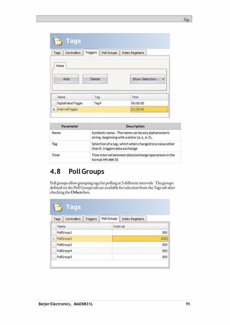
Tags
Parameter Description
Name Symbolic name. Thenamecanbeanyalphanumericstring, beginningwith a letter (a-z, A-Z).
Tag Selectionof a tag,whichwhenchanged to a valueotherthan0, triggers data exchange
Time Time interval betweendataexchangeoperations in theformatHH:MM:SS
4.8 PollGroups
Poll groups allow grouping tags for polling at 5 different intervals. The groupsdefined on the PollGroups tab are available for selection from theTags tab afterchecking theOthers box.
Beijer Electronics, MAEN831L 95

Tags
Parameter Description
Name Symbolic name. Thenamecanbeanyalphanumericstring, beginningwith a letter (a-z, A-Z).
Interval Polling interval inms
4.9 StationHandling
For some controllers, it is possible for the operator to define fromwhich controllerstation to read orwrite values. The station number is given as a prefix to thecontroller address.The stationnumber for each controller is defined on theControllers tab of theTags configuration page, by clicking the Settings button.The default station is set on the Settings tab, and the stations are defined on theStations tab.
In this example, from anEthernet driver, Station 0 is the default station.
Beijer Electronics, MAEN831L 96

Tags
The default station is the station addressedwithout using a prefix. The otherstations can be addressed either as a fixednumber or as an index register. Withfixed stationnumbers, an object is always connected to the same controlleraddress, and only the value of this controller address can be used in the object.When addressing for exampleD10 in station 2, the following syntax is used:2:D10
Related information
Using IndexRegisters for StationHandling
4.10 IndexRegisters
With index addressing, it is possible for the operator to select fromwhich tag anobject is to collect the shown value. Without index addressing an object is alwaysconnected to the same controller address, and only the value of this address canbe shown in the object.
Beijer Electronics, MAEN831L 97

Tags
Which tags to use for indexing are defined on the IndexRegisters tab of the tagsconfiguration page. Up to eight different index registers can be used for eachcontroller, and each index register can be used formore than one object. Indexregisters can be connected to any tag in the global tag list, but the tag has to beselected for each controller.Tags are connected to index registers on theTags tab.In general index addressing can be formulated as:Display value = the content in tag (the object’s address + the content in the indexregister)If the content in the index register is 2, and the address of the tag specified in theobject is 100, the value shown in the object will be collected from address 102.If the value in the index register is changed to 3, the value in the object will becollected from address 103 instead.
4.10.1 IndexAddressingExample
Using index registersmay be convenientwhen for example controlling torque andspeed of a number of connectedmotors from the same screen,without having toconfigure and displaymaneuverable objects for eachmotor.The following example is based upon the presumption of threemotors, and thetorque and speed of eachmotor is held in a different tag:
Motor1 Motor2 Motor3
Torque Speed Torque Speed Torque Speed
D11 D21 D12 D22 D13 D23
1. Create a project where theDemoController is selected as controller.
Beijer Electronics, MAEN831L 98
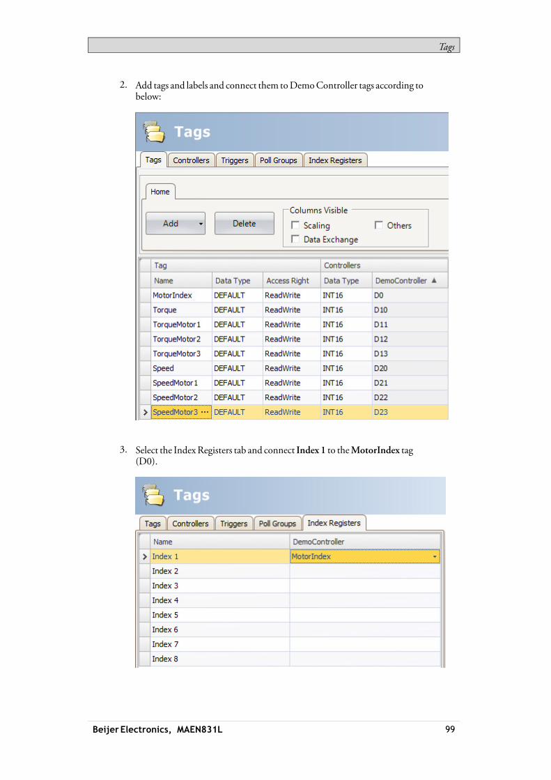
Tags
2. Add tags and labels and connect them toDemoController tags according tobelow:
3. Select the IndexRegisters tab and connect Index 1 to theMotorIndex tag(D0).
Beijer Electronics, MAEN831L 99

Tags
4. Select theTags tab again and check theOthers box in order to display theIndexRegisters column.
5. Connect theTorque and Speed tags to IndexRegister 1.
6. Now, create aComboBox object for selection ofmotor, and two analognumeric objects thatwill display (or set) theTorque and Speed tags for eachmotor. Also add explaining labels.
7. ClickConfigureTexts for theComboBox object, connect the object to theMotorIndex tag, and add three texts and values according to below.
8. Connect the analog numeric objects to theTorque andSpeed tags.9. In order to test that the index addressingworks even thoughno controller is
connected, addmaneuverable objects, e.g. sliders, and connect them to theD11–D13 andD21–D23 tags.
Beijer Electronics, MAEN831L 100
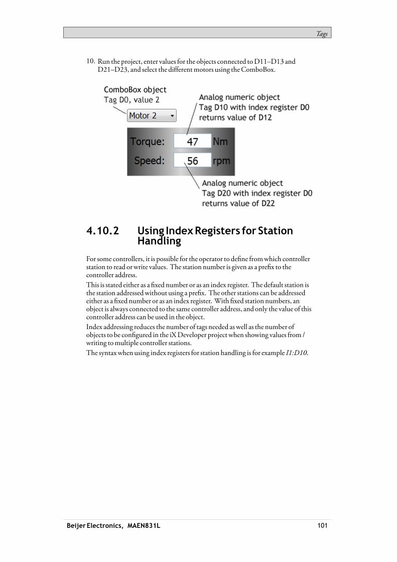
Tags
10. Run the project, enter values for the objects connected toD11–D13 andD21–D23, and select the differentmotors using theComboBox.
4.10.2 Using IndexRegisters for StationHandling
For some controllers, it is possible for the operator to define fromwhich controllerstation to read orwrite values. The station number is given as a prefix to thecontroller address.This is stated either as a fixed number or as an index register. The default station isthe station addressedwithout using a prefix. The other stations can be addressedeither as a fixed number or as an index register. With fixed station numbers, anobject is always connected to the same controller address, and only the value of thiscontroller address can be used in the object.Index addressing reduces the number of tags needed aswell as the number ofobjects to be configured in the iXDeveloper project when showing values from /writing tomultiple controller stations.The syntaxwhenusing index registers for station handling is for example I1:D10.
Beijer Electronics, MAEN831L 101

Tags
Thismeans that the value in the controller address connected to Index 1will pointoutwhich controller station number to read orwrite values.
Beijer Electronics, MAEN831L 102

Tags
Related information
StationHandling
4.11 Expressions
TheExpressions functionality is usedwhen connecting an object to a tag andthe purpose is not to use the tag value as it is. Expressions enable the user to e.g.extract a bit froma tag, add a dynamic offset or gain, and then to use this value fora specific object.
Note:Static offset andgain for a tag is set in the tags configurationpage.
The same expression can be connected tomore than one object in the project.
4.11.1 Definition
An expression is a one line return statement inC#. The default expression code is“value”.
4.11.2 UsingExpressions
Right-click on an object and then click the button ... next to SelectTag. TheExpressions dialog is displayed.
Beijer Electronics, MAEN831L 103

Tags
ClickNew to create an expression and expression group (optional). Existingexpressions are available from the Select Expressiondrop-downmenu. Use theEdit andDelete buttons to edit or delete existing expressions.Select among the tags, operators and functions to insert. It is also possible totype the expressionmanually, butwithout assistance from IntelliSense (autocompletion). If an expression is not valid, an errormessage is givenwhenvalidating the project. The expression is run, when the value of the original tagthat is connected to the object is changed.Expressions added to an object in a project are available only in the current project.If an object with a local expression is saved into theComponent Library, the objectcan be used in an other project, but the expression is not included. In order to reuseexpressions, they have to be saved in the expressions library.
Related information
LibraryExpressions
4.11.3 LibraryExpressions
Examples of expressions (how to extract bits from an int) are includedwheninstalling iXDeveloper and can be added to the project by clickingLoad.Expressions can be reused in other projects by saving them in the expressionlibrary. Select the expression in the drop-down list and clickSave. The expressionis saved to a file in the PC.To load the expression in another project, clickLoad. A
Beijer Electronics, MAEN831L 104

Tags
selection dialog is displayed. Select the expression in the drop-down list and clickOK.If you have saved expressions to the library that youwant to remove, clickDeleteand select among the saved expressions in a dialog. Expressions includedwheninstalling iXDeveloper are not listed, since these cannot be deleted.
4.11.4 Limitations
An expression is executed only on read, i.e. when the value is changed in thecontroller.Whenwriting a value (from e.g. an analog numeric tag), the expression is notexecuted.If another tag than the original tag is used in the expression, the expression is nottriggered on its value change.If an expression that is used inmore than one location is either renamed or deleted,references are not updated. A build error is given.Expressions can be used for all data connections except for• actions• the Property grid• recipe item tags• current language tag inMultiple languages configuration• trigger tags• index tags• scheduler tags• dynamic text for alarm items
Expressions use explicit bool comparison.
Example:Donotuse: value;Globals.Tags.Tag1.ValueUse: value != 0;GlobalsTags.Tag1.Vaule ==1
4.12 DataExchange
Data exchange betweendifferent controllers is supported; also between controllersof different brands. The data exchange can be performedwhen a digital tag is set,or at a certain time interval. Data exchange can be selected for individual tags,array tags or for the complete range of tags.
Note:Thedataexchange function is isolated fromgeneral tag/controller settings. Forexample, a tag assigned readaccess only for theoperator,may still be readandwrittenby thedata exchange function.
Follow the steps below to set up data exchangewith three different controllersinvolved:
Beijer Electronics, MAEN831L 105
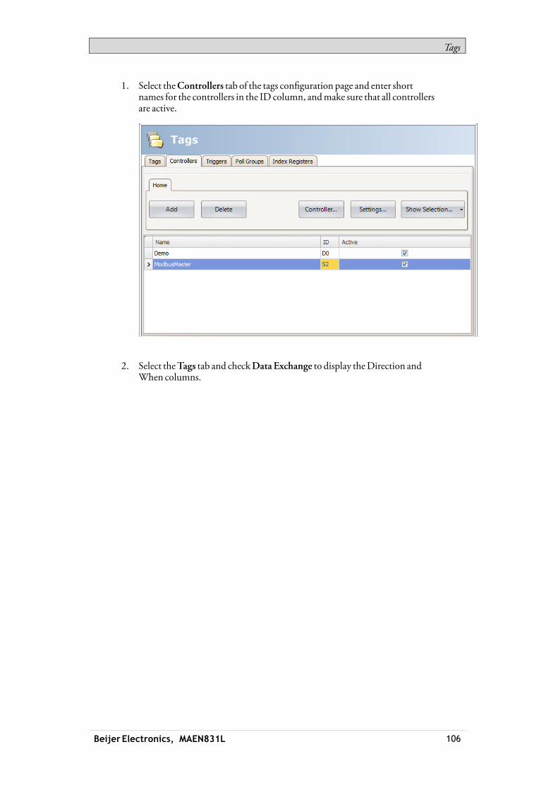
Tags
1. Select theControllers tab of the tags configuration page and enter shortnames for the controllers in the ID column, andmake sure that all controllersare active.
2. Select theTags tab and checkData Exchange to display theDirection andWhen columns.
Beijer Electronics, MAEN831L 106

Tags
3. Select an address that is represented in all of the controllers.
If an array tag is selected, the complete address range corresponding to thearray sizewill be exchanged:
Beijer Electronics, MAEN831L 107

Tags
4. Click ... in theDirection column to set up the direction of the data exchange.
5. Add a trigger tag on theTriggers tabwith time interval for data exchangeor use a tag, whichwhen greater than 0,will trigger the data exchange.Alternatively, set up a trigger that includes both value change and a timeinterval.
Beijer Electronics, MAEN831L 108

Tags
6. Return to theTags tab and select which trigger to use.
Note:If thepoll group containsmany tag values that change frequently, the time requiredfor themtobehandled couldexceed the set poll time. This could lead toproblemsupdating thedataexchangebetween thecontrollers. Set thePollGroup Interval to ahigher valueor use a time trigger to control thedataexchangeoperations.
Related information
Triggers
4.13 ImportingandExportingTags
Tags can be imported to and exported from an iXDeveloper project, to, forexample, be edited inExcel or a text editor, or to be transferred to another project.The complete tag listmay be imported and exported, or the actions can be basedon connected controllers.The import function also allows selecting individual tags for import.
4.13.1 HandlingColumns
The import function allows skipping columns, or binding columns in the importfile to any column in theTags configuration page.TheName andDataType columnsmust always be bound.A columnmay only be bound once.
4.13.2 Saving the ImportConfiguration
For repetitive import actions the import configuration, e.g. how columns arebound and fromwhich row to start the import, can be saved and reused. Theimport configuration is saved by clicking the Savemapping as importmodulebutton prior to performing the import. Next time the ImportTags dialog isopened, the configuration is available from the Importmoduledrop-down list.Saving import configurations is valid only for files in text or Excel format.
Beijer Electronics, MAEN831L 109

Tags
Note:In order to import or export .xls-filesMicrosoft Excelmust be installed.
4.13.3 Tag ImportExample
If the controller in the project is changed to a systemwith other names for the tagsused, thesemust be changed:1. Click onTags in the Project Explorer.2. Click on the arrow to the right of the Import/Exportbutton to display the
available options of import and export operations.
3. SelectExport tags from the desired controller to export the list to a text file oranExcel sheet. Enter a file name andbrowse to a location. Define how theto separate the columns andwhich columns to export. Use the arrows if youwant to change position of the columns.
Note:In order to import or export .xls-filesMicrosoft Excelmust be installed.
Beijer Electronics, MAEN831L 110
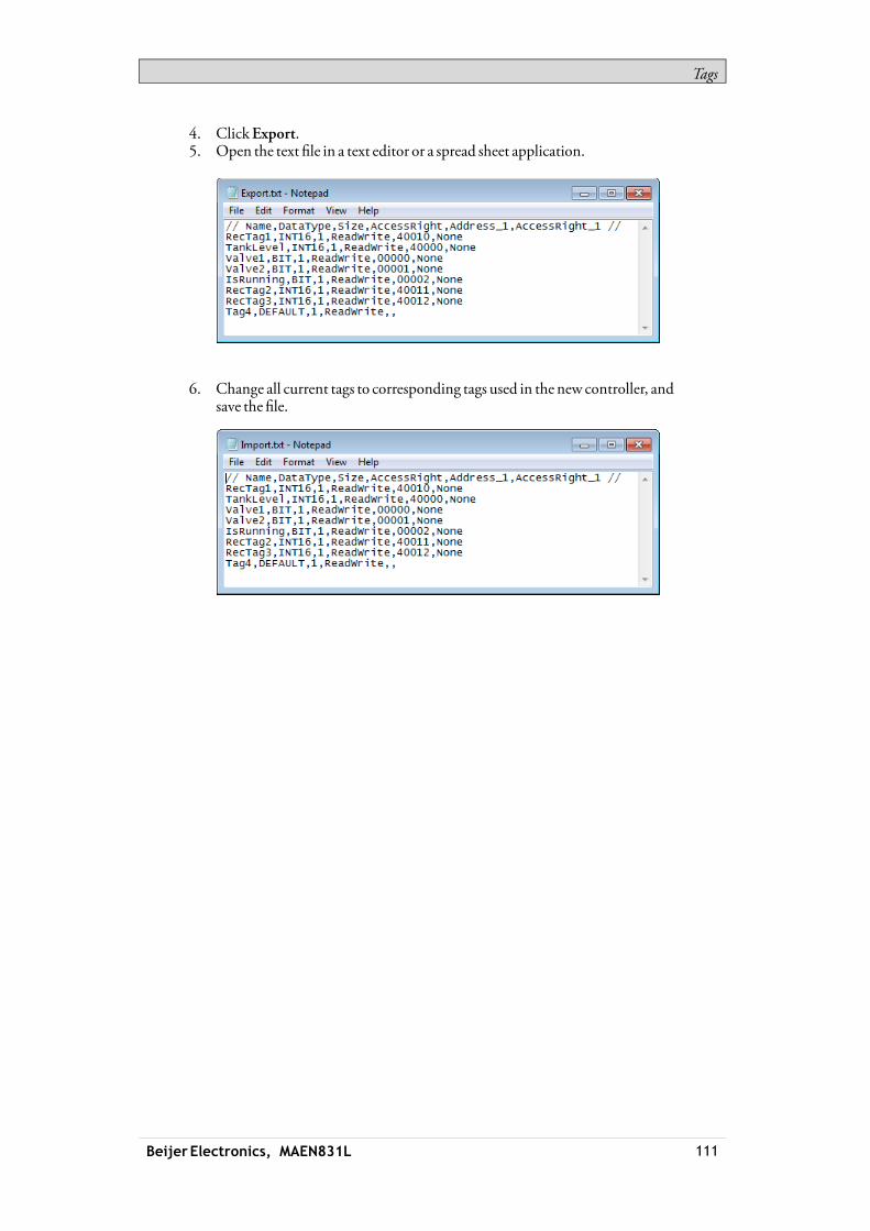
Tags
4. ClickExport.5. Open the text file in a text editor or a spread sheet application.
6. Change all current tags to corresponding tags used in the new controller, andsave the file.
Beijer Electronics, MAEN831L 111

Tags
7. Select Import tags to the desired controller and browse to the updatedfile. If desired, select a row fromwhich to start the import. It is possible torebind columns before importing to the project, and to exclude columns.These settings can be saved by clicking the Savemapping as importmodulebutton, andwill then bemade available for selection from the Importmoduledrop-down list at next import.
Beijer Electronics, MAEN831L 112

Tags
8. Click Import. It is nowpossible to deselect import of some tags.
Beijer Electronics, MAEN831L 113
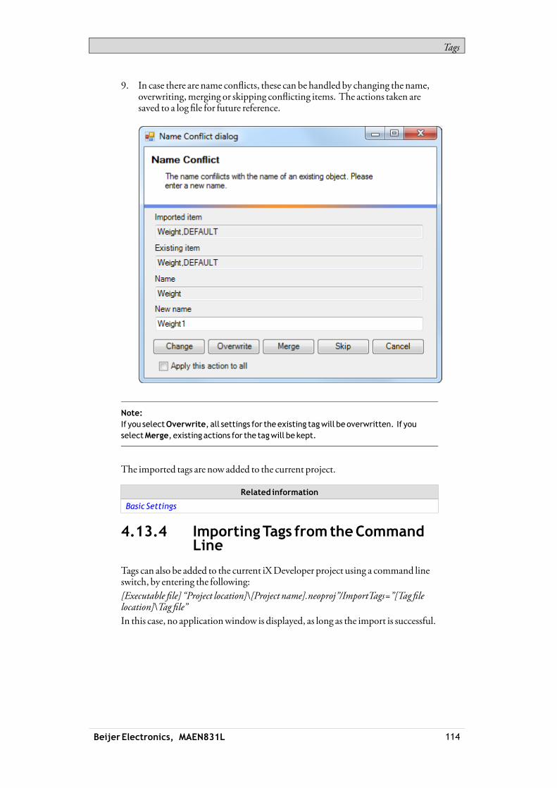
Tags
9. In case there are name conflicts, these can be handled by changing the name,overwriting,merging or skipping conflicting items. The actions taken aresaved to a log file for future reference.
Note:If you selectOverwrite, all settings for theexisting tagwill beoverwritten. If youselectMerge, existing actions for the tagwill be kept.
The imported tags are now added to the current project.
Related information
Basic Settings
4.13.4 ImportingTags fromtheCommandLine
Tags can also be added to the current iXDeveloper project using a command lineswitch, by entering the following:[Executable file] “Project location]\[Project name].neoproj”/ImportTags=”[Tag filelocation]\Tag file”In this case, no applicationwindow is displayed, as long as the import is successful.
Beijer Electronics, MAEN831L 114
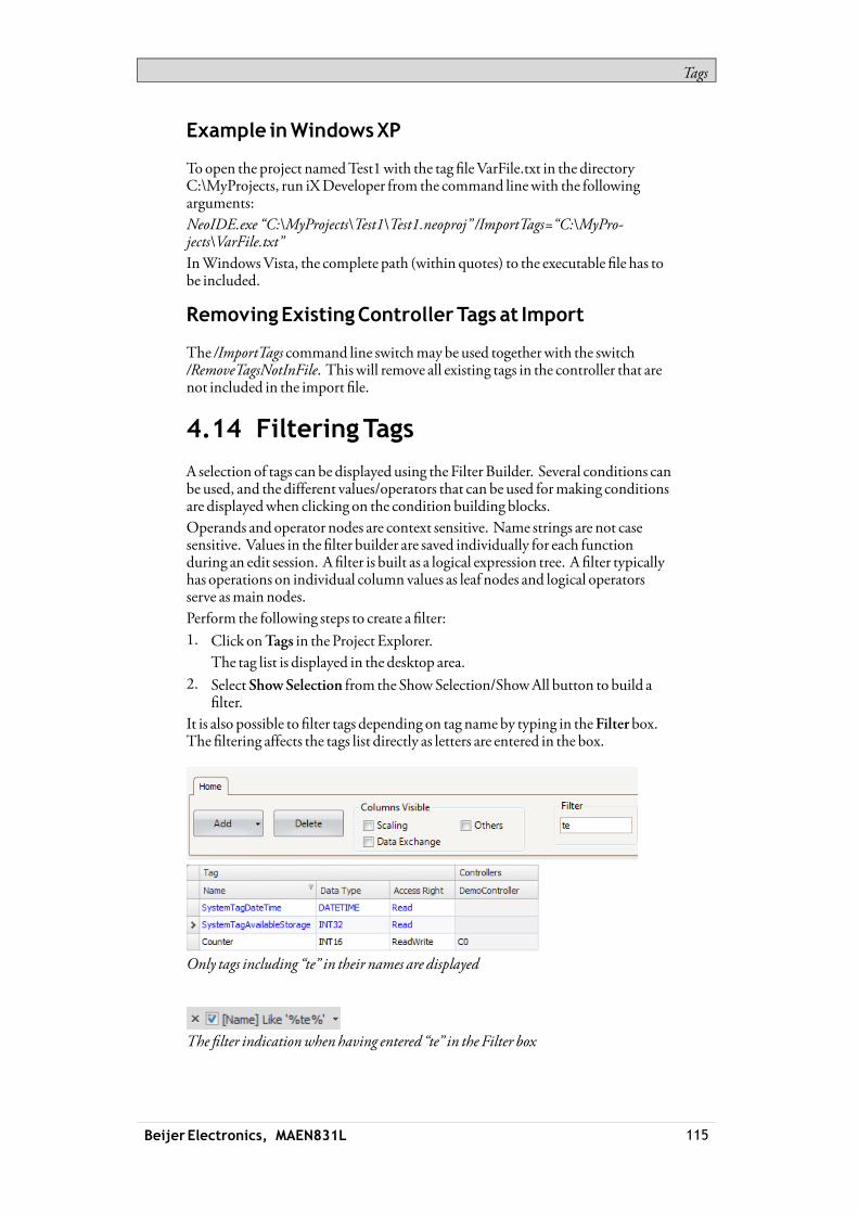
Tags
Example inWindowsXP
Toopen the project namedTest1with the tag fileVarFile.txt in the directoryC:\MyProjects, run iXDeveloper from the command linewith the followingarguments:NeoIDE.exe “C:\MyProjects\Test1\Test1.neoproj” /ImportTags=“C:\MyPro-jects\VarFile.txt”InWindowsVista, the complete path (within quotes) to the executable file has tobe included.
RemovingExistingControllerTags at Import
The /ImportTags command line switchmay be used togetherwith the switch/RemoveTagsNotInFile. This will remove all existing tags in the controller that arenot included in the import file.
4.14 FilteringTags
A selection of tags can be displayed using the Filter Builder. Several conditions canbe used, and the different values/operators that can be used formaking conditionsare displayedwhen clicking on the condition building blocks.Operands and operator nodes are context sensitive. Name strings are not casesensitive. Values in the filter builder are saved individually for each functionduring an edit session. A filter is built as a logical expression tree. A filter typicallyhas operations on individual column values as leaf nodes and logical operatorsserve asmain nodes.Perform the following steps to create a filter:1. Click onTags in the Project Explorer.
The tag list is displayed in the desktop area.2. Select ShowSelection from the ShowSelection/ShowAll button to build a
filter.It is also possible to filter tags depending on tag nameby typing in theFilterbox.The filtering affects the tags list directly as letters are entered in the box.
Only tags including “te” in their names are displayed
The filter indicationwhen having entered “te” in the Filter box
Beijer Electronics, MAEN831L 115

Tags
Related information
Filtering Items
4.15 TagFormat
The following tag formats (data types) are available in the dialog for a tag, providedthat the selected driver orOPC server supports the tag format.
Format Data type Range
DEFAULT Treatedas INT16
Bit BIT 0and1
Bit BOOL Values canbe“false” (0) or “true” (1)(1)
Signed16-bit INT16 -32,768 – +32,767
Unsigned16-bit UINT16 0 – +65,535
Signed32-bit INT32 -2,147,483,648 – +2,147,483,647(2)
Unsigned32-bit UINT32 0– +4,294,967,295(2)
Floatwithexponent,64-bit
DOUBLE 1.7 ×10308 (1)
Floatwithexponent,32-bit
FLOAT ±3.4 ×1038 (1)
7 × Signed16-bit DATETIME AnAnalogNumeric object canpresent the timeformat(1)
Syntax(3): <yyyy-MM-ddhh:mm:ss>7 consecutiveregisters areused to store a time:
Dx, seconds, 0–59
Dx+1,minutes, 0–59
Dx+2, hours, 0–23
Dx+3, day, 1–31
Dx+4,month, 1–12
Dx+5, year, 100–9999
Dx+6,weekday, 1–7
String STRING Storing character strings in tags. For this data type,size canbe selected.
(1)Controller representation for this type is dependent on thedriver software.(2)Regarding resolution of values in 32-bit format: both iXDeveloper and theoperatorpanel canhandleup to six decimal digits of an integer 32-bit value. Remainingdigitswill be truncatedor changed into zeros.(3)yyyy=year,MM=month,dd=date,hh=hour,mm=minute, ss=second.
For use in script code, the following table shows the type representation inC#.This is usedwhen there is a need to do a type casting, for example in calculationsthat are using overloaded operators.
Beijer Electronics, MAEN831L 116
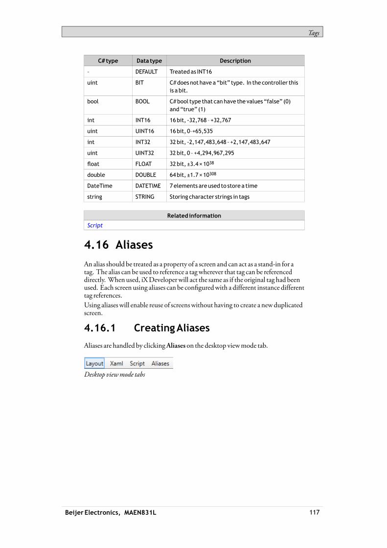
Tags
C# type Data type Description
– DEFAULT Treatedas INT16
uint BIT C#doesnot have a“bit” type. In the controller thisis a bit.
bool BOOL C#bool type that canhave the values “false” (0)and“true” (1)
int INT16 16bit, -32,768 – +32,767
uint UINT16 16bit, 0–+65,535
int INT32 32bit, -2,147,483,648 – +2,147,483,647
uint UINT32 32bit, 0 – +4,294,967,295
float FLOAT 32bit, ±3.4 ×1038
double DOUBLE 64bit, ±1.7 ×10308
DateTime DATETIME 7elements areused to store a time
string STRING Storing character strings in tags
Related information
Script
4.16 Aliases
An alias should be treated as a property of a screen and can act as a stand-in for atag. The alias can be used to reference a tagwherever that tag can be referenceddirectly. When used, iXDeveloperwill act the same as if the original tag had beenused. Each screen using aliases can be configuredwith a different instance differenttag references.Using aliases will enable reuse of screenswithout having to create a newduplicatedscreen.
4.16.1 CreatingAliases
Aliases are handled by clickingAliases on the desktop viewmode tab.
Desktop viewmode tabs
Beijer Electronics, MAEN831L 117

Tags
Clicking theAdd button adds an alias to the list. Make settings for each addedalias. When predefined values are available, these can be selected by clicking thearrow at the right of the table cell.
Basic Settings
EnterAlias name andDefault value for the alias. If no default value is entered, thealiaswill be treated as a local screen variable.
Parameter Description
AliasName Symbolic name. Thenamecanbeanyalphanumeric string,beginningwith a letter (a-z, A-Z).
DefaultValue Selectionof tags to createaliases of. If no tag is selectedthe aliaswill be treatedas a local screenvariable.
Thedefault valuewill be thedefault value for thealias inthe created instances. Itwill also be the reference for thedefault instance. See Instances.
DataType Selectionof data type. This setting is enabledby firstclicking theDataTypecheckbox.
Thedata typewill by default reflect thedata typeof theselectedDefault Value.
4.16.2 Instances
The aliases created in the project are presented in a table on the instances tab. Itis possible to change the value for the aliases in this tab, in order to override thedefault value configured in the aliases tab.If a value for an alias is changed in the instances tab, the new value is displayedwithbold text to indicate that it differs from the alias’ default value.To revert back to thedefault value, delete the value followed by pressing [Enter].Thedefault value can be changed in the aliases tab.
Beijer Electronics, MAEN831L 118

Tags
Parameter Description
Instance Symbolic name. Thenamecanbeanyalphanumeric string,beginningwith a letter (a-z, A-Z).
Aliases Thenames of all aliases created in theprojectwill bedisplayed in the columnsheaders. Thevalues connectedto thealiaseswill be listed in each columns.
Using the“ShowScreen”Actionwith Instances
The "ShowScreen” action can be used to display a specific screen. For screensthat have aliases, it is also possible to select which instance of the screen to use, andthereby alsowhich set of tags to assign to the screen’s aliases.TheDefault option is a virtual instance configuredwith the alias’ default values.
“ShowScreen” Action Parameters.
Related information
ActionGroups
Limitations
• Aliases do not support array tags.• Aliases can not be used in connectionwith expressions.• Aliases can not be usedwith theTrendViewer object.• Aliases can not be used on background screens.• No scripting support for value changed event on an alias.
Beijer Electronics, MAEN831L 119

Controller
5 Controller
iX panels can be connected tomany types of automation equipment, such asPLCs, servos, anddrives.The expression controller is used as a general term for the connected equipment.It is possible to connect a tag tomore than one controller simultaneously.Thismakes it possible to use the same applicationwith different controllers.Controllers can be enabled anddisabled in runtime. A project can containmultiple controller connections.A project can also be connected to an externalOPC server.
Related information
MultipleControllers
ExternalOPCServer
InternalTags
5.1 AddingaController
When anewproject is created, one of the steps is to choosewhich controller brandandmodel to connect to. Clicking onTags in the Project Explorer, selecting theController tab displays theController configuration page.
Beijer Electronics, MAEN831L 120

Controller
Parameter Description
Name Symbolic name. Thenamecanbeanyalphanumericstring, beginningwith a letter (a-z, A-Z).
ID Optional short name for controller; displayed in functionssuchasDataexchange.
Active Selectionofwhich controllers are tobeactive in runtime.Changeof active controllers canalso beperformed inruntimeusing anactionor script.
Controllers are added and deleted using theAdd andDelete buttons.ClickingController allows selecting another controller, andSettingsdisplayssettings for the selected driver.ClickingHelp in the driver settings dialog opens the help file for the driver.
Related information
SelectController
5.1.1 NotifyWindow
If a communication error between the application and the controller is detectedin runtime, this will result in a communication error, and aNotifyWindowwillbe displayed in the operator panel. TheNotifyWindow is a floatingwindow thatstarts in the upper left corner of the screen. It is also used to display the alarmindicator.TheNotifyWindow can bemoved to any position on the current screen.
5.2 DEMOController
TheDEMOcontroller is used and selected in the sameway as a regular controllerdriver, to design and test a project directly on the development PCwithoutconnection to an external controller.A number of predefined tags can be selected:
Data type Tag ID Description
BIT,BOOL M0 -M99 Digital tags
INT16,UINT16 D0 -D99 Analog tags
TheDEMOcontroller also includes counters anddigital tagswith predefinedfunctions:
Data type Tag ID Description
BIT M100 -M104 TogglesOFFandONevery 1,000ms
INT16 C0 -C4 Counts from0 to100with1,000ms intervalbydefault;min/maxvalues canbedefined
Beijer Electronics, MAEN831L 121
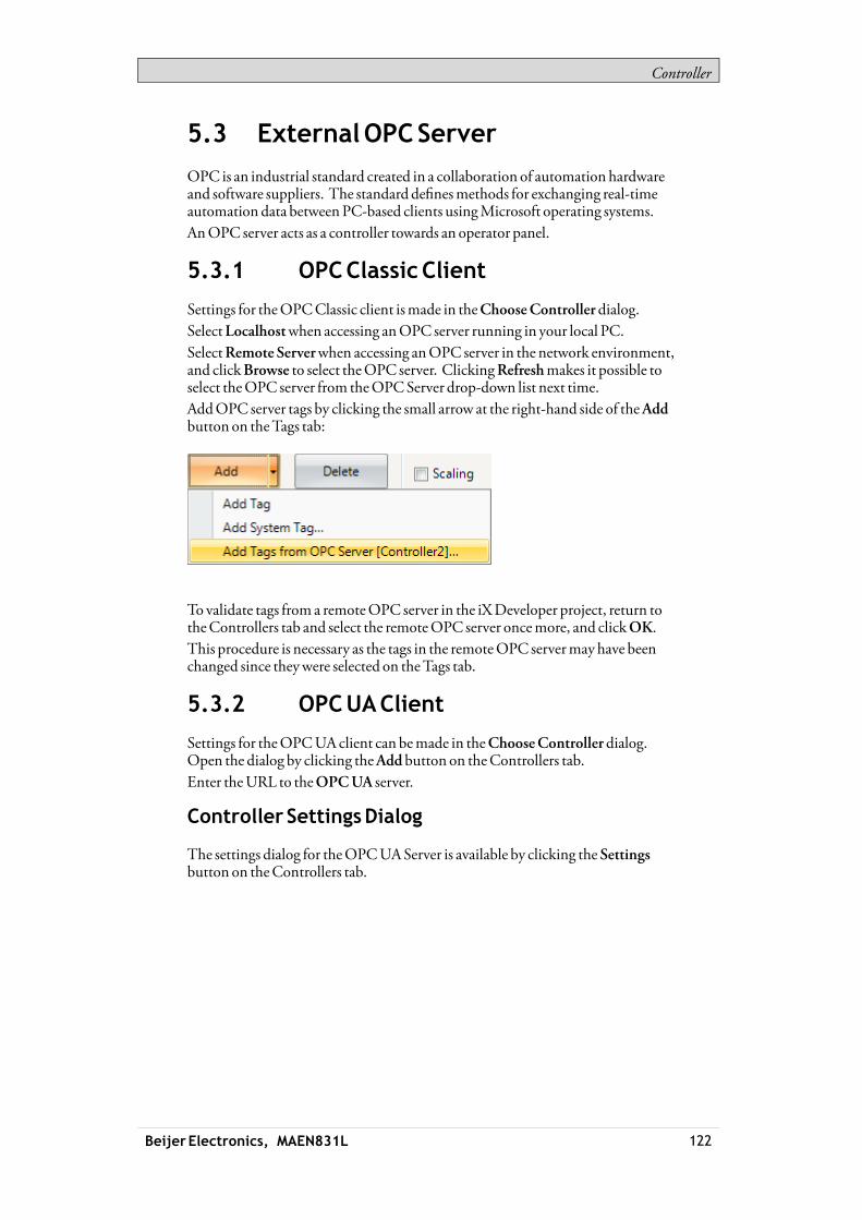
Controller
5.3 ExternalOPCServer
OPC is an industrial standard created in a collaboration of automation hardwareand software suppliers. The standard definesmethods for exchanging real-timeautomation data betweenPC-based clients usingMicrosoft operating systems.AnOPC server acts as a controller towards an operator panel.
5.3.1 OPCClassicClient
Settings for theOPCClassic client ismade in theChooseControllerdialog.SelectLocalhostwhen accessing anOPC server running in your local PC.SelectRemote Serverwhen accessing anOPC server in the network environment,and clickBrowse to select theOPC server. ClickingRefreshmakes it possible toselect theOPC server from theOPCServer drop-down list next time.AddOPC server tags by clicking the small arrow at the right-hand side of theAddbutton on theTags tab:
To validate tags from a remoteOPC server in the iXDeveloper project, return totheControllers tab and select the remoteOPC server oncemore, and clickOK.This procedure is necessary as the tags in the remoteOPC servermayhave beenchanged since theywere selected on theTags tab.
5.3.2 OPCUAClient
Settings for theOPCUAclient can bemade in theChooseControllerdialog.Open the dialog by clicking theAddbutton on theControllers tab.Enter theURL to theOPCUA server.
Controller SettingsDialog
The settings dialog for theOPCUAServer is available by clicking theSettingsbutton on theControllers tab.
Beijer Electronics, MAEN831L 122

Controller
Parameter Description
URL EnterURL to theOPCUA server.
OnlyUATCPBinary is supportedwhichmeans theURLmuststartwith “opc.tcp://”
Authenticationsettings
Choosewhether to useanonymous login or enter ausernameandpassword toenable a secured login.
Namespace settings This setting offers apossibility to declare anamespaceURIandbind it to aprefix.
Namespace separator character: Enter a character tobeused to separate thenamespaceURI prefix fromthe tag IDwhenpresentedon the tag tab.
TagViewsettings
Default namespace: Select thedefault namespaceURIprefix tobeusedwhenenteringa tag on the tag tab.
Maxsubscriptions: Enter themaximumnumber ofsubscriptions supportedby the server(1)
Subscription settings
Max itemsper subscription: Enter themaximumnumberof itemsper subscription supportedby the server(1)
(1) Please refer to the servermanual for limitations
AddTags fromOPCUAServer
AddOPCUAserver tags by clicking theAddbutton on theTags tab.Enter theTag ID alongwith the preferred namespaceURI prefix, defined in thecontroller settings dialog. Make sure to separate the valueswith the separatorcharacter.Example: “NS3:tag” .TheTag ID, in the example above, correspondswithBrowseName in theOPCUA server.
Beijer Electronics, MAEN831L 123

Controller
If no namespaceURI prefix is entered, the default namespaceURI prefix asdefined in the controller settings dialogwill be used.Noprefix is neededwhen connecting to an iX server.
Note:Array tags are not supportedbyOPCUAcontrollers.
SupportedFunctions
DataAccess (UApart 8) is supported.All variables of data types that are used in iXDeveloper is supported. Read /writeof objects, structs and arrays is not supported.
Limitations
Limitation Description
Browsing Browsing of servers / nodes is not supported.
Address input inGUI NameSpaceandBrowseName is used to identify avariable in the server.
If this combination is not unique, the client cannot identifythe variable.
This is not aproblemwhenconnecting to an iX server, sinceall tag names (variables) areunique.
Related information
OPCUAServer
5.4 UpdatingDrivers
Drivers can be updated via Internet or fromfile.
Beijer Electronics, MAEN831L 124
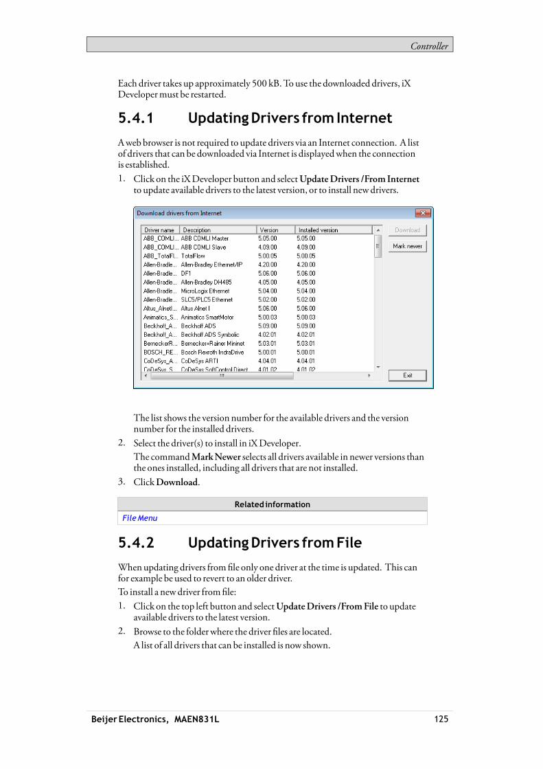
Controller
Each driver takes up approximately 500 kB.To use the downloaded drivers, iXDevelopermust be restarted.
5.4.1 UpdatingDrivers from Internet
Awebbrowser is not required to update drivers via an Internet connection. A listof drivers that can be downloaded via Internet is displayedwhen the connectionis established.1. Click on the iXDeveloper button and selectUpdateDrivers /From Internet
to update available drivers to the latest version, or to install newdrivers.
The list shows the version number for the available drivers and the versionnumber for the installed drivers.
2. Select the driver(s) to install in iXDeveloper.The commandMarkNewer selects all drivers available in newer versions thanthe ones installed, including all drivers that are not installed.
3. ClickDownload.
Related information
FileMenu
5.4.2 UpdatingDrivers fromFile
Whenupdating drivers fromfile only one driver at the time is updated. This canfor example be used to revert to an older driver.To install a newdriver fromfile:1. Click on the top left button and selectUpdateDrivers /FromFile to update
available drivers to the latest version.2. Browse to the folderwhere the driver files are located.
A list of all drivers that can be installed is now shown.
Beijer Electronics, MAEN831L 125

Controller
3. Select the driver to install in iXDeveloper.MarkNewer selects the driver when there is a newer version than the currentlyinstalled.
4. Click Install.
Related information
FileMenu
5.5 Synchronizing theControllerClock
In order to synchronize the controller clockwith the iXDeveloper project, thesystem tags hour,minute, second, need to be added to the project from theTagsconfiguration page. These are then connected to addresses in the controller.
When the value is changed in any of the system tags, theywill bewritten to thecontroller.
Related information
SystemTags
Beijer Electronics, MAEN831L 126
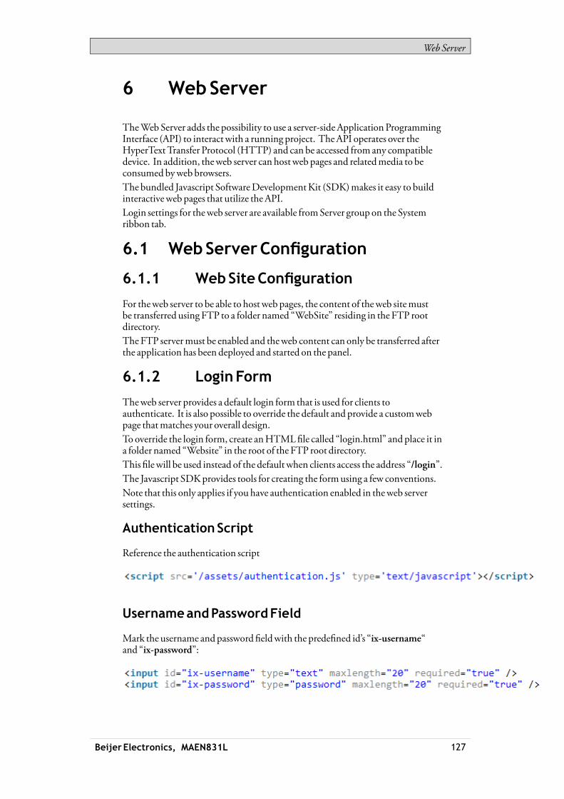
WebServer
6 WebServer
TheWebServer adds the possibility to use a server-sideApplicationProgrammingInterface (API) to interact with a running project. TheAPI operates over theHyperTextTransfer Protocol (HTTP) and can be accessed from any compatibledevice. In addition, theweb server can hostweb pages and relatedmedia to beconsumed byweb browsers.The bundled Javascript SoftwareDevelopmentKit (SDK)makes it easy to buildinteractiveweb pages that utilize theAPI.Login settings for theweb server are available fromServer group on the Systemribbon tab.
6.1 WebServerConfiguration
6.1.1 WebSiteConfiguration
For theweb server to be able to host web pages, the content of theweb sitemustbe transferred using FTP to a folder named “WebSite” residing in the FTP rootdirectory.The FTP servermust be enabled and theweb content can only be transferred afterthe application has been deployed and started on the panel.
6.1.2 LoginForm
Theweb server provides a default login form that is used for clients toauthenticate. It is also possible to override the default and provide a customwebpage thatmatches your overall design.To override the login form, create anHTMLfile called “login.html” and place it ina folder named “Website” in the root of the FTP root directory.This filewill be used instead of the default when clients access the address “/login”.The Javascript SDKprovides tools for creating the formusing a few conventions.Note that this only applies if you have authentication enabled in theweb serversettings.
AuthenticationScript
Reference the authentication script
UsernameandPasswordField
Mark the username andpassword fieldwith the predefined id’s “ix-username“and “ix-password”:
Beijer Electronics, MAEN831L 127

WebServer
LoginButton
Mark a login buttonwith the predefined id “ix-login”. Any element can be used.
InvalidCredentials
Optionally add an elementwith the predefined id “ix-invalid-credentials” thatwill be shown if the login fails.
6.2 Javascript SDK
6.2.1 Javascript SDKOverview
The JavaScript SDKprovides a rich set of client-side functionality for accessingthe server-sideAPI calls. This enables the possibility to build highly interactiveweb pages that uses tags defined in the project.1. The first step to build an interactiveweb page is to reference the SDKby
inserting the following script into to the header of the html.
Note:TheSDK is bundledwith jQuery 1.7 (http://jquery.com/).
2. Next, the SDKneeds to be initialized. In its simples form the following linesneed to be added after the reference to the SDK:
Thiswillmake it possible to use the defined tagmetadata attributes to incorporatethe project tags into theweb page.The following linewill, for example, insert the value ofTag1 into theHTMLdocument:
Beijer Electronics, MAEN831L 128

WebServer
TagValueorProperties
To insert the current value of a tag or tag property into aHTMLelement, thedata-ix-tag attribute can be used. The value of the attribute should be the nameof the tag as defined in the project and the property of a tag. Separate the nameswith a dot “.”.If no property is provided, the value of the tag is used.
Formatting
Formatting of a tag value can be applied to a tag of numeric type or a datetime. Theformat is defined using thedata-ix-format attribute.
The following table describes the customdate and time format specifiers anddisplays a result string produced by each format specifier.Tuesday, February 07, 2012 12:27:24 PM is used as input.
Tagvalue Description Result
d Thedayof themonth, from01 through31. 07
D Theabbreviatednameof thedayof theweek (inenglish)
Tue
j Theday of themonth, from1 through 31 7
l The full nameof thedayof theweek Tuesday
S Ordinal number for thedateof themonth (eg -st, -nd,-rd, -th etc)
th
w Dayof theweekas anumber. 2
z Day of the year 37
W Weekof the year 05
F The full nameof themonth. February
m Gets theday of themonth from00 to 31 02
M Theabbreviatednameof themonth. Feb
n Themonth of the year 1 to 12 2
t Number of days in themonth 29
L Is leap year, 1 if true, otherwise 0 1
Y Theyear as a four-digit number. 2012
Beijer Electronics, MAEN831L 129

WebServer
Tagvalue Description Result
y Theyear, from00 to 99 12
a TheAM/PMdesignator lower case. pm
A TheAM/PMdesignator upper case. PM
g Thehour, using a12-hour clock from1 to12. 12
G Thehour, using a24-hour clock from0 to23. 12
h Thehour, using a12-hour clock from01 to 12. 12
H Thehour, using a24-hour clock from00 to 23. 12
i Theminute, from00 through59 27
s The second, from00 through59. 24
X Themilliseconds, from000 through 999. 000
O Hours offset fromGMT,with a leading zero for asingle-digit value.
+0100
Z Timezoneoffset, in seconds 3600
q Quarter 1
Beijer Electronics, MAEN831L 130

WebServer
The following table describes the customnumeric format specifiers and displayssample output produced by each format specifier:
ResultTagValue
DescriptionValue Format
4 00→ 04
4.5 0.00→ 4.50
0 Digit
.1 0.00×1000 →1.00 ×10-01
# Digit, zero showsas absent 4 ##→ 4
. Decimal separator ormonetarydecimal separator
4.5 0.00→ 4.50
5.55 0.0 × 1000→ 5.6 ×1000E Separatesmantissa andexponentin scientificnotation 1000000 0.0 × 1000→ 1.0 ×1006
1000 0,0→ 1,000, Grouping separator
1000 0,#→ 1,000
-5 plus;minus→minus
5 plus;minus→plus
0 plus;minus;zero→ zero
; Separates positive andnegativesubpatterns
-5 0;(0.0);0.000→ (5.0)
700 [>500]###.##;[<1000]###;###.#→ 700.00
400 [>500]medium;[>1000]###;###.#→400
[] Customsubpatterns
1001 [>2000]high;[>1000]nor-mal;[>500]low→normal
SettingTagValue
To set the value of a tag, two elementsmust be defined.The first element have thedata-ix-setter attribute on the positionwhere the tagvalue can be entered.The second element has thedata-ix-submitbutton attribute used to submit thenew tag value.Thedata-ix-submitbutton attribute takes the tag names, separated by comma“,”, to be submittedwhen the button is clicked. To submit all tags an asterisk “*”can be used.
Beijer Electronics, MAEN831L 131
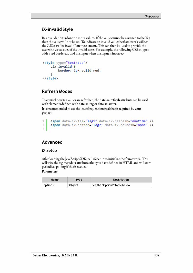
WebServer
iX-invalid Style
Basic validation is done on input values. If the value cannot be assigned to theTagthen the valuewill not be set. To indicate an invalid value the frameworkwill settheCSS class “ix-invalid” on the element. This can then be used to provide theuserwith visual cues of the invalid state. For example, the followingCSS snippetadds a red border around the inputwhen the input is incorrect:
RefreshModes
To control how tag values are refreshed, thedata-ix-refresh attribute can be usedwith elements definedwithdata-ix-tag ordata-ix-setter.It is recommended to use the least frequent interval that is required by yourproject.
Advanced
iX.setup
After loading the JavaScript SDK, call iX.setup to initialize the framework. Thiswill wire the tagmetadata attributes that you have defined inHTMLandwill startperiodical polling if this is needed.Parameters:
Name Type Description
options Object See the“Options” tablebelow.
Beijer Electronics, MAEN831L 132

WebServer
Options
Property Type Description ArgumentDe-fault
refreshInterval Int The refresh interval of tag valuesinms. Forperformance reasonsit is recommendednot to use lowvalues for this setting.
Optional 5000
refreshMode String Overrides thedefault refreshmodeof tag values.
Acceptedmodes are: none,onetime, interval.
Optional one-time
refreshMode-Setter
String Overrides thedefault refreshmodeof tag setters.
Acceptedmodes are: none,onetime, interval.
Optional one-time
Example:This examplewill set periodical refresh interval to 10 seconds, set the refreshmodeofHTMLelementsmarkedwith thedata-ix-tag attribute to interval and set therefreshmode ofHTMLelementsmarkedwith thedata-ix-setter attribute torefresh only once.
iX.refreshElements
Refreshes the tag values of the provided elementsmanually. The attributedata-ix-refreshbutton can be used to achieve the same function.
Note:Only anelement that havebeenmarkedwith a valid data-ix-tag or data-ix-setter canbe refreshed. Thevaluewill be refreshed regardless of the refreshmode set on theelement.
Parameters:
Name Type Description
elementIds Array A list of strings containing theHTMLelementids. If not providedall tagelements areupdated.
Example:This example showhowyouprogrammatically can achieve the same behaviorasmarking an elementwithdata-ix-refreshbutton. In the example, theHTMLelementwith id "tag1Id"will be updatedwhen the elementwith id"refreshButton" is clicked. This example uses jQuery (bundledwith iX.js) to bindto the click event of the "refreshButton"
Beijer Electronics, MAEN831L 133

WebServer
InHTML:
In Javascript:
iX.refreshTags
Refreshes the tag values of the provided tag namesmanually.
Note:Only tags used in conjunctionwithdata-ix-tag or data-ix-setter or createdbyiX.createTag canbe refreshed.
Parameters:
Name Type Description
tagName String (Optional) A list of strings containing thenamesof the tags to refresh. If not providedall defined tags are refreshed.
Example:This example showhow to programmatically refresh the tag values of "tag1" and"tag2". When refreshButton is clicked the "tag1" and "tag2"will be refreshed evenif the refreshmodewas set to 'none' when creating the tag.
iX.createTag
Creates a representation of a server-side tag on the client-side.Parameters:
Beijer Electronics, MAEN831L 134

WebServer
Name Type Description
tagName String Thenameof the tag in theproject tocreatea connection to.
valueRefreshedCallback Function Optional: Function that is calledwhenthe tag valuehas changed. The functionis not calledwhen the tag value is thesameas last checked.
Functionmay take twooptionalparameters. Thefirst parameter isthe tag that changed the value, thesecond theold values of the tagbefore itchanged.
refreshMode String Optional: Overrides thedefault refreshmodeof tag. Acceptedmodes are: none,onetime, interval.
Note that themore frequentrefreshMode is always used. Forexample, if the tag is createdwithonetimebut anelementdefinesdata-ix-refreshmode=”interval” forthe same tag then the tagwill have arefreshModeof interval.
Returns:
Type Description
iX.Tag An instanceof iX.Tag. SeeTagClass for a completedescription.
Example:This example showhow to display awarning if the value of "tag1" exceeds 70. Theexample is using jQuery (bundledwith iX.js) to hide and show thewarning box.
iX.getTag
Retrieves a tag by name.Parameters:
Name Type Description
tagName String Thenameof the tag to retrieve.
Beijer Electronics, MAEN831L 135

WebServer
Returns:
Type Description
iX.Tag An instanceof iX.Tag. SeeTagClass for a completedescription.
Example:This example shows how to retrieve an instance of a tag after it has been created."tag1" and "tag1Again"will refer to the same tag instance.
iX.commitTagValue
Commits any unsaved tag values thatwas changed using iX.Tag.setValue for theprovided tag names.Parameters:
Name Type Description
tagNames Array (Optional) A list of strings containing thenames of the tags to commit. If not providedall defined tags are committed.
Example:This example showhow to commit changes to tag values on the server in a batch.Note that the valuemustmatch the data type of the tag on the server.
TagClass
iX.Tag is a class representing aTag. Themethods and properties of aTagmustbe accessed through an instance of iX.Tag and not the class itself. Typically aTaginstance obtained using iX.createTag or iX.getTagmethods.
Beijer Electronics, MAEN831L 136

WebServer
iX.TagProperties
Name Type Description
isDirty Bool Flag indicating if the local value has beenchanged.
tagProperties Object Anobjectwithdata retrieved fromthe server.See tagmetadatabelow. Note that theseareonly available after thefirst refresh. Also, onlyvalue is refreshednot all of themetadata.
value Flexible Thevalueof the tag. The typeof the valuedepends on thedata type in theproject. Neveruse this property to set the value.
TagProperties:
Name Type Description
controllers Array Anarrayof controller names that the tag isconnected to.
description String The tagdescription, null if not defined.
dataType String The tagdataType, e.g int16,datetime,default
initialValue Flexible The initial valueof the tag, null if not defined.
readonly Bool True if the tag is readonly, otherwise false
quality String Indicates thequality of the tag value:Unknown,Good,Bad
iX.Tag.setValue
Set the tag valuemanually. To commit the value to the server side call iX.commit.It’s vital that the value that is set corresponds to the data type of the tag.Parameter:
Name Type Description
newValue Flexible Thenewvalue. Mustmatch thedata typeofthe tag.
iX.Tag.subscribeToChange
Adds a callback that is calledwhen the server-side value has changed.
Parameter:
Name Type Description
fn Function Thecallback to register
Beijer Electronics, MAEN831L 137

WebServer
iX.Tag.unsubscribeToChange
Unsubscribe from changes.
Name Type Description
fn Function The samecallback thatwasusedwithiX.Tag.subscribeToChange
iX.Tag.refresh
Refreshes this tag. It is recommended to refresh tags in batch (using iX.refresh)instead of refreshing individual tags.
iX.Tag.commit
Commit this tags value if the value has been changed. It is recommended tocommit tags in batch (using iX.commit) instead of refreshing individual tags.
6.3 WebServiceAPI
6.3.1 RESTfulWebServiceAPI
iXDeveloper provides anAPI for interactingwith tags. The tags can be read orwritten to using theHTTP verbsGET,PUT andPOST.GET to read tags,PUTto set the value of a tag orPOST to performbatch operation.
6.3.2 General
AcceptedTypes
It is possible to negotiatewhichmedia type thatwill be returned as a representationof the resource being retrieved. Use theAccept header in the request to specify thedesiredmedia type. text/html and application/jsonmedia types are understood asresponse formats for tag related resources.A client request providing an unsupportedmedia typewill be respondedwith thefollowingmessage: “406 -Not understood”.
6.3.3 RESTAPI
TagsResource
Lists tags available in the project.
TagsResource
Verbs: GET
Uri: /Tags
Beijer Electronics, MAEN831L 138

WebServer
TagsResourceExample
TagResource
Resource for interactingwith individual tags. Toperformmultiple operations ontags it is recommended to useTagBatch resource instead.
TagResource
Verbs: GET, PUT
Uri: /tags/:name
GETparams: Name: Thenameof the tag, e.g., Tag1 SystemTagDateTime
Name: Thenameof the tag, e.g., Tag1 SystemTagDateTimePUTparams:
Value: Thevalue to set the tag to, e.g., 12, "foo"
TagResourceExample
TagBatchResource
TheTagBatch resource is a resource used to performbatch operations on tags.
TagBatchResource
Verbs: POST
Uri: /tagbatch
Beijer Electronics, MAEN831L 139

WebServer
TagBatchResource
includeMetadata: boolean indicating if only the tag valueor thefull tagmetadata shouldbe fetched
getTags: List of tag names to return
POSTparams:
setTags: List name, valuepairs representing new tagvalues.
Beijer Electronics, MAEN831L 140
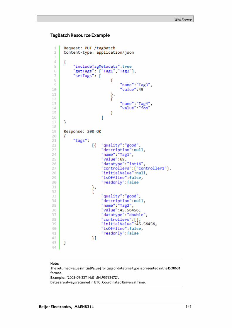
WebServer
TagBatchResourceExample
Note:The returned value (initialValue) for tags of datetime type is presented in the ISO8601format.Example: "2008-09-22T14:01:54.9571247Z".Dates are always returned inUTC,CoordinatedUniversal Time.
Beijer Electronics, MAEN831L 141
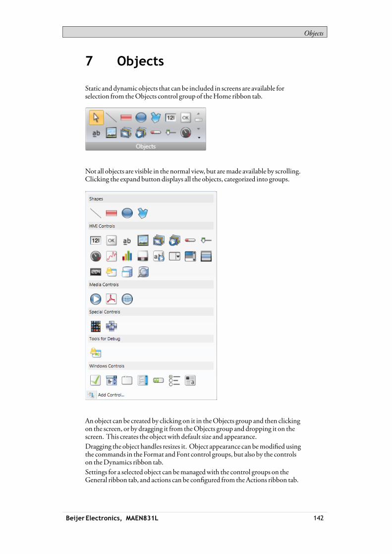
Objects
7 Objects
Static and dynamic objects that can be included in screens are available forselection from theObjects control group of theHome ribbon tab.
Not all objects are visible in the normal view, but aremade available by scrolling.Clicking the expand button displays all the objects, categorized into groups.
An object can be created by clicking on it in theObjects group and then clickingon the screen, or by dragging it from theObjects group and dropping it on thescreen. This creates the object with default size and appearance.Dragging the object handles resizes it. Object appearance can bemodified usingthe commands in the Format andFont control groups, but also by the controlson theDynamics ribbon tab.Settings for a selected object can bemanagedwith the control groups on theGeneral ribbon tab, and actions can be configured from theActions ribbon tab.
Beijer Electronics, MAEN831L 142
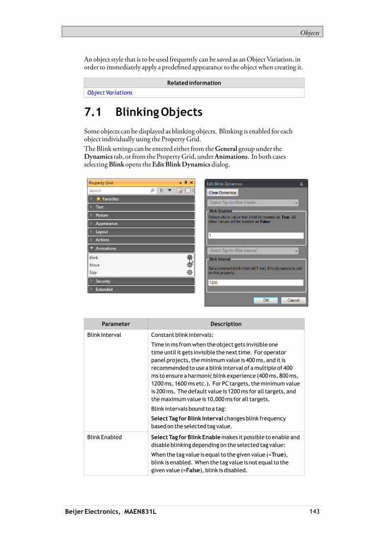
Objects
Anobject style that is to be used frequently can be saved as anObjectVariation, inorder to immediately apply a predefined appearance to the object when creating it.
Related information
ObjectVariations
7.1 BlinkingObjects
Some objects can be displayed as blinking objects. Blinking is enabled for eachobject individually using the PropertyGrid.TheBlink settings can be entered either from theGeneral group under theDynamics tab, or from the PropertyGrid, underAnimations. In both casesselectingBlink opens theEdit BlinkDynamicsdialog.
Parameter Description
Blink Interval Constant blink intervals:
Time inms fromwhen theobject gets invisible onetimeuntil it gets invisible thenext time. Foroperatorpanel projects, theminimumvalue is 400ms, and it isrecommended touseablink interval of amultiple of 400ms toensureaharmonic blink experience (400ms, 800ms,1200ms, 1600msetc.). For PC targets, theminimumvalueis 200ms. Thedefault value is 1200ms for all targets, andthemaximumvalue is 10,000ms for all targets.
Blink intervals bound to a tag:
SelectTag forBlink Interval changesblink frequencybasedon the selected tag value.
Blink Enabled SelectTag forBlinkEnablemakes it possible to enable anddisableblinkingdepending on the selected tag value:
When the tag value is equal to the given value (=True),blink is enabled. When the tag value is not equal to thegiven value (=False), blink is disabled.
Beijer Electronics, MAEN831L 143

Objects
Security has higher priority than blink, and an object hidden by security cannotbemade visible through blink.It is not recommend to useBlink onobjects that should be used for userinteraction.
Related information
GeneralGroup
7.1.1 Limitations foroperatorpanelTargets
Blink is not supported for the following objects in operator panel targets:
AlarmDistributorViewer
AlarmViewer Audit Trail Viewer
CheckBox ComboBox DatabaseViewer
GroupBox List Box Media Player
PdfViewer Progress Bar RadioButton
WebBrowser - -
Related information
GeneralGroup
7.2 Shapes
Static shapes such as Line, Rectangle andPoly Line can be used to drawbackground graphics. Tags can be linked to shapes underDynamics, to changetheir appearance (e.g. color andposition) depending on value changes ofcontroller tags.Points for an existing Poly Line object can be adjusted by selectingEdit Pointsfrom the contextmenu.
Ellipse Line Polyline Rectangle
Note:Bevel for Poly Line andEllipse is only supported for projects designed for PC targets.
7.3 HMIControls
Dynamic objects such as buttons, analog numerics, sliders,meters and trendviewers are linked to tags in order to create control andmonitoring functions.The tag associatedwith an object can be selected and changed from theTag/Security group on theHomeorGeneral ribbon tabs, or from the context
Beijer Electronics, MAEN831L 144

Objects
menu. Links to tags (controller tags, internal tags or system tags) are selected intheTag drop-down list.Objects containing text can be edited directly from the keyboard, either when justcreated, orwhen a single selection is done on the text area of the object.It is also possible to use script code to control the text contents of buttons, textsor text boxes.
Note:Useof braces arounddigits, such as ‘{0}’, is not allowed in text objects. Thiswill resultin anerrorwhenopening the screen.
The followingHMI controls are described:
ActionMenuObject
AlarmViewerObject
AnalogNumericObject
AnimatedGIF
AnimatedLabelObject
Audit Trail Viewer ButtonObject CircularMeterObject
ChartObject DatabaseViewerObject
Digital ClockObject
LinearMeterObject
Multi PictureObject
PictureObject Roller PanelObject
SliderObject
TextObject TouchComboBoxObject
TouchList BoxObject
TrendViewerObject
7.3.1 ActionMenuObject
TheActionmenuobject is used to displaymultiplemenu groups, each containingits own sets of actionswhich can be triggered in iXRuntime from the actionmenuobject.Settings for theActionMenuobject are available from theGeneral ribbon tabwhile the object is selected:
Beijer Electronics, MAEN831L 145

Objects
SettingsGroup
Parameter Description
Edit Actions Opens theEdit Actions dialog
View type ChoosebetweenBar, ExpandandTab
ItemWidth Set thewidthof the items. This is only available for theBarandExpandView types.
ItemHeight Set the height of the items
Orientation Set the orientationof the items. This is only available fortheBarView type.
PictureWidth Set thewidthof thepictures for the items
PictureHeight Set the height of thepictures for the items
ScrollBarWidth Set thewidthof the scroll bar.
TouchSettingsGroup
Parameter Description
Scroll Sensitivity Set the sensitivity of the scroll. Minimumvalue is 1,maximumvalue is 10.
EditActionsDialog
TheActions tab in theEdit Actions dialog contains the following properties:
Parameter Description
Text The text tobedisplayed for the item
Picture Thepicture tobedisplayed for the item
MakeTransparent Set transparencyon the item
Action Configure the actionwhen the item is clicked
TheMenuGroups tab in the Edit Actions dialog contains the followingproperties:
Parameter Description
MenuGroupName Thenameof themenugroup
Picture Thepicture tobedisplayed for themenugroup
MakeTransparent Set transparencyon themenugroup
Note:Make surenot to use semi-transparent pictures in projects targeted for operator panel.Since these targets donot fully support opacity, semi-transparent picturesmay turnout unclear.
Beijer Electronics, MAEN831L 146

Objects
AddingaNewAction
In theEdit Actionsdialog select theActions tab. Click theAddbutton. Anewitemwill be added and placed last in the list. To configure the actions for the item,click the “…”button in theAction column.
AddingaNewMenuGroup
In theEdit Actionsdialog select theMenuGroups tab. Click theAdd button. Anewmenu groupwill be added andplaced last in the list. Themenu groupwill bedisplayed in theActions tab as a newmenu group tab.
ActionMenuDynamics
It is also possible to set dynamics, i.e. tag dependent values for theActionMenuproperties. These can be found in theDynamics tab in the ribbon bar.
Related information
DynamicsRibbonTab
7.3.2 AlarmViewerObject
TheAlarmViewer is used to display andmanage alarm items, for exampleindication of out-of-bounds tag values. The viewer consists of a list area and abutton area.
Related information
AlarmManagement
AlarmViewer
7.3.3 AnalogNumericObject
TheAnalogNumeric object displays a boxwith a numeric or alphanumeric value.The value can be connected to a tag.Settings for the analog numeric object are available from theGeneral ribbon tabwhile the object is selected:
DisplayFormatGroup
Parameter Description
Type Selectionof Integer,Decimal, String,HexorBinarydisplayformat
Number ofDecimals Maximumnumber of decimals to display in theobject.
Only availablewhenType=Decimal. Thenumber ofdecimalswill be representedby a“#” symbol on theanalognumeric object.
Beijer Electronics, MAEN831L 147

Objects
Parameter Description
Limit Characters to Makes it possible tomaximize thenumber of displayedcharacters. Thenumber of characterswill be representedbya“#” symbol on theanalog numeric object.
Zero Fill Fills empty character positionswith zeros, to let themaximumnumber of characters alwaysbedisplayed
Note:The“LimitCharacters to” function, in combinationwith the string format type isnot supported for theTraditional Chinese, SimplifiedChineseand SimplifiedChinese(Compact) languages.
Prefix/SuffixGroup
Parameter Description
Prefix/Suffix Text value thatwill precede/follow theobject value
Tag/SecurityGroup
Parameter Description
Select Tag Connection to a tag fromthe tags configuration page
Select SecurityGroups Allows limiting access of the object basedon securitygroups. If left empty, theobject canbeaccessedbyanyone.
SelectVisibility Configuration of visibility:
Default: Thevisibility specifiedon theGeneral tabof theSecurityManager is used.
Disabled: Theobject is disabled for userswith insufficientaccess rights
Hidden: Theobject is invisible for userswith insufficientaccess rights
Normal: Theobject looks normal also for userswithinsufficient access rights
FormatGroup
Parameter Description
Auto StretchFont Resizes the font tofit theheight of theobject. Defaultsetting for theanalognumeric object.
DisableOperator Input Disables input in runtime
Transparent Makes theobject transparent, i.e. makes the frameandbackgroundcolor invisible
Beijer Electronics, MAEN831L 148

Objects
TextAlignmentGroup
Parameter Description
Horizontal /Vertical Adjusts theobject horizontally or vertically
ValidationGroup
Parameter Description
On Input Input values are validated, basedonLower Limit andUpper Limit,when thebox is checked
OnDisplay Backgroundcolor changes according toOtherColors on theFormat tab if upperor lower limit are violated,when thebox is checked
Lower Limit/UpperLimit
Minimum/maximumvalue that canbeentered inruntimewhenOn Input is checked, or thatwill changethebackgroundcolor of theobjectwhenOnDisplay ischecked
Note:The font sizeof theanalognumeric object is auto-sizedwhen resizing theobject framebydefault, and is not adjusted in the Font control of theHome ribbon tab. UncheckAuto StretchFont in theText groupfirst, and then change the font size on theHomeribbon tab.
7.3.4 AnimatedGIF
TheAnimatedGIF (Graphics Interchange Format) object allows includingamoving graphic picture in the iXDeveloper project. AnimatedGIFs canbe imported to the project by browsing the PC environment for graphicfiles. Imported animatedGIFs are added to the Project Picture folder in theComponent Library.TheAnimatedGIF can be connected to a tagwhich controls animation. Whenthe value of the connected tag is 0, then animation is turned off and the picture isdisplayed static in its initial design. AnAnimatedGIFnot connected to a tag runsanimated continuously.Settings for theAnimatedGIF object are available from theGeneral ribbon tabwhile the object is selected:
SettingsGroup
Parameter Description
ChangePicture Opens abrowsedialog for selectionof picture
Reset Picture Restores original height andwidth topicture
Stretch Adapts height andwidth to the selection framewhenresizing thepicture
Transparent Makes theobject transparent, i.e. makes the frameandbackgroundcolor invisible
Beijer Electronics, MAEN831L 149

Objects
Note:Make surenot to use semi-transparent pictures in projects targeted for operator panel.Since these targets donot fully support opacity, semi-transparent picturesmay turnout unclear.
Tag/SecurityGroup
Parameter Description
Select Tag Connection to a tag fromthe tags configuration page
Select SecurityGroups Allows limiting access of the object basedon securitygroups. If left empty, theobject canbeaccessedbyanyone.
SelectVisibility Configuration of visibility:
Default: Thevisibility specifiedon theGeneral tabof theSecurityManager is used.
Disabled: Theobject is disabled for userswith insufficientaccess rights
Hidden: Theobject is invisible for userswith insufficientaccess rights
Normal: Theobject looks normal also for userswithinsufficient access rights
7.3.5 AnimatedLabelObject
TheAnimated Label object is used to display an animated text label iniXRuntime.Settings for theAnimated Label object are available from theGeneral ribbon tabwhile the object is selected:
Note:Using theanimated label object creates a slightly higher loadon theCPU.
Parameter Description
Text The text tobedisplayed in theanimated label
Animated If enabled, the text starts to animate
Animation speed Set the speed for theanimation. Minimumvalue is 1,maximumvalue is 32,767.
AnimationDirection Set the animationdirection:
Fromright to left
From left to right
Fromright to left to right
From left to right to left
Fromdown toup
Fromup todown
Fromdown toup todown
Fromup todown toup
Beijer Electronics, MAEN831L 150

Objects
AnimatedLabelDynamics
It is possible to set dynamics, i.e. tag dependent values for theAnimated Labelproperties. These can be found in theDynamics tab in the ribbon bar.
Related information
DynamicsRibbonTab
7.3.6 AuditTrail ViewerObject
TheAudit Trail Viewer displays information about operator changes that havebeen loggedwith the audit trail function.
Related information
Audit Trail
Audit Trail Viewer
7.3.7 ButtonObject
TheButton tool draws a buttonwith a text and/or picture. The button can beconfigured to performa specific task in runtime via theActions ribbon tab or usingscript. The text on the button object can also be set to depend directly on a tagvalue using theGeneral control on theDynamics ribbon tab. If a picture is used,the picture file is added to the Project Pictures folder in theComponent Library.Settings for the button object are available from theGeneral ribbon tabwhile theobject is selected:
PictureGroup
Parameter Description
Picture Selects apicture todisplayon thebutton. Pictures fromtheProject Pictures folder is available for selectiondirectly. It is also possible tobrowse thePCenvironmentfor apicture.
SelectNoPicture to removeapreviously selectedpicture.
Checking theMulti Picture checkboxwillmakeit possible todisplay different pictures basedonthe valueof a connected tag according to sectionConfigureMulti Pictures.
Multi Picture Multi Pictureor single picturedisplayedonbutton.
Transparent Makes thepicture transparent
Note:Make surenot to use semi-transparent pictures in projects targeted for operator panel.Since these targets donot fully support opacity, semi-transparent picturesmay turnout unclear.
Beijer Electronics, MAEN831L 151

Objects
ConfigureMulti Pictures
Different pictures can be displayed on the button based on the value of aconnected tag, following the steps below:1. Check theMulti Picture checkbox.2. Click on thePicture control on the Picture group of theGeneral tab.3. Select a tag to control which picture to display.4. ClickAdd to addpictures and configure start and end values for each picture.
You can browse the PC for pictures, or select pictures from the current project.
5. ClickOK.The picture on the buttonwill now change according to the value of theselected tag. When the value is out of limits, no picture is displayed.
PictureAlignmentGroup
Parameter Description
Vertical Alignment/Horizontal Alignment
Set alignment for thepicture
Clicking the small arrow in the lower right corner of the PictureAlignment groupdisplays the picture propertieswith a number of additional picture settings.
StyleGroup
Parameter Description
Style Predefinedgraphical styles for thebutton
Appearance Theappearanceof thebutton, includingpossibility tomake thebutton roundedand settings for eachcorner ofthebutton.
Additional predefined styles for this object are found in theObjectVariationsgroup.
Beijer Electronics, MAEN831L 152

Objects
Note:Whenediting default button styleproperties, for example corner radius, appearancein runtimemay sometimesdiffer fromwhendesigning theproject in iXDeveloper.
Related information
ObjectVariations
TextGroup
Parameter Description
Text Text displayedon thebutton
Multiline Lets the text run overmore thanone line, using [Enter].
Confirm the text entrybypressing [Ctrl] + [Enter].
WordWrap Wraps the text tofit thewidthof thebutton
ConfigureTexts Links thedisplayed text to a tag. TheTextfield value isshown if the selected tag is notwithin the set limits
TextAlignmentGroup
Parameter Description
Horizontal /Vertical Adjusts the text on thebuttonhorizontally or vertically
VisibilityGroup
Parameter Description
Transparent Makes theobject transparent
CreatingaButtonwithMomentaryFunction
In order to create a buttonwith amomentary function, youneed to combine a SetTag action forMouseDownwith aResetTag action forMouseUp .
Related information
ActionsRibbonTab
Script
Component Library
Beijer Electronics, MAEN831L 153

Objects
7.3.8 CircularMeterObject
TheCircularMeter represents a numeric value, and displays the value of aconnected tag.Different styles can be used to change the graphical profile of themeter, and also ifthemeter is to be full, half or quarter.
Circularmeters in Black Full style, ChromeHalf style andVintageQuarter style
Settings for themeter object are available from theGeneral ribbon tabwhile theobject is selected:
Angular SettingsGroup
Parameter Description
Start Angle /EndAngle Determines theplacement of the scale on themeter.Theangular value is basedona start (0 degrees) at threeo’clock, in a counter clockwisedirection fromthere. TheStart Anglemust differ fromtheEndAngle.
TextRotation SelectParallel to let thenumbers follow theoutlineof themeter, orNone to display thenumbers alignedhorizontally.
Clockwise Determines rotation orientation, clockwiseor counterclockwise.
RegionSettingsGroup
Parameter Description
LowRegion/MediumRegion /HighRegionMin/Max
Definecolors for up to 3 regions, andatwhich values tostart and stopeach region. Entering 0 for bothminimumandmaximumvaluesdisplays no region color.
ValueScaleGroup
Parameter Description
MinValue/MaxValue Start/end valueof scale.
These values can consist of onedecimal digit.
Major Ticks Numberof labeled scalemarks on themeter
Minor Ticks Numberof scale ticks between twoadjacentmajor ticks
Beijer Electronics, MAEN831L 154

Objects
StyleGroup
Parameter Description
Style Predefinedgraphical styles for themeter. The smallerstyles are intended inparticular to allow full visibility inthe smaller operator panels.
Appearance Theappearanceof themeter; full, half or quarter
Additional predefined styles for this object are found in theObjectVariationsgroup.
Related information
ObjectVariations
Needle SettingsGroup
Parameter Description
AnalogAnimation Animation that creates a smoothmovement of theneedleat value change.
Oscillation Animation of needle initially oscillating around thenewvalue. The function is only available in combinationwithAnalogAnimation.
WhenAnalogAnimation is selected, it is possible to activateShortest Path in theproperty grid underAppearance. The setting affects the direction of the animatedneedle, resulting in a counter clockwisemovement if this is the shortest pathbetween two indicated values.
Note:TheShortest Pathproperty is not available for PC targets.
Note:Using animationon thecircularmeterobjects creates ahigher loadon theCPU.Therefore it is recommended to limit theuseof theneedle animation to only a fewcircularmeters per screen, especially for the smaller panelmodels.
Tag/SecurityGroup
Parameter Description
Select Tag Connection to a tag fromthe tags configuration page
Select SecurityGroups Allows limiting access of the object basedon securitygroups. If left empty, theobject canbeaccessedbyanyone.
SelectVisibility Configuration of visibility:
Default: Thevisibility specifiedon theGeneral tabof theSecurityManager is used.
Beijer Electronics, MAEN831L 155

Objects
Parameter Description
Disabled: Theobject is disabled for userswith insufficientaccess rights
Hidden: Theobject is invisible for userswith insufficientaccess rights
Normal: Theobject looks normal also for userswithinsufficient access rights
VisibilityGroup
Parameter Description
Transparent Makes theobject transparent
Scale Whenunchecked, the scale color of themeter ismadetransparent. Scale color is set fromOtherColors on theFormat tab.
7.3.9 ChartObject
The chart object is used to display values of connected array tags.Settings for the chart object are available from theGeneral ribbon tabwhile theobject is selected:
Chart SettingsGroup
Parameter Description
Edit Series Add, removeandedit the current series for this chart
Chart Types Choose chart type. Available types are:
Area
AreaHorizontal
Bar
Bar Join
Donut
Histogram
Kagi
Line
LineFast
LineHorizontal
LinePoint
Pie
Points
Radar
Header Set the name that is displayedabove thechart
3DView Set a3D lookand feel for the chart
Beijer Electronics, MAEN831L 156

Objects
XAxis SettingsGroup
Parameter Description
Visible Set the visibility of theX axis
GridVisible Set the visibility of theX axis grid lines.
Automatic Automatically calculates theminimumandmaximumXaxis values. Overrides theMinimumandMaximumproperties
Minimum Set theminimumvalueof theXaxis. If automatic is set,this value is ignored
Maximum Set themaximumvalue of theXaxis. If automatic is set,this value is ignored
Y1Axis SettingsGroup
Parameter Description
Visible Set the visibility of theY1axis
GridVisible Set the visibility of theY1axis grid lines.
Automatic Automatically calculates theminimumandmaximumY1axis values. Overrides theMinimumandMaximumproperties.
Minimum Set theminimumvalueof theY1axis. If automatic is set,this value is ignored.
Maximum Set themaximumvalue of theY1axis. If automatic is set,this value is ignored. Whenusing chartswith visible labelson curves themaximumvalue is extended tomake roomfor label.
Y2Axis SettingsGroup
Parameter Description
Visible Set the visibility of theY2axis
GridVisible Set the visibility of theY2axis grid lines.
Automatic Automatically calculates theminimumandmaximumY2axis values. Overrides theMinimumandMaximumproperties.
Minimum Set theminimumvalueof theY2axis. If automatic is set,this value is ignored.
Maximum Set themaximumvalue of theY2axis. If automatic is set,this value is ignored. Whenusing chartswith visible labelson curves themaximumvalue is extended tomake roomfor label.
Beijer Electronics, MAEN831L 157
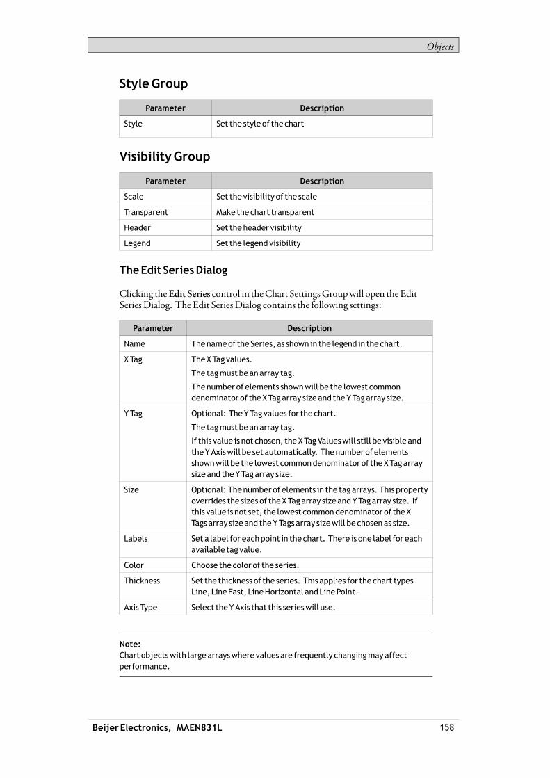
Objects
StyleGroup
Parameter Description
Style Set the style of the chart
VisibilityGroup
Parameter Description
Scale Set the visibility of the scale
Transparent Make the chart transparent
Header Set the header visibility
Legend Set the legend visibility
TheEdit SeriesDialog
Clicking theEdit Series control in theChart SettingsGroupwill open theEditSeriesDialog. The Edit SeriesDialog contains the following settings:
Parameter Description
Name Thenameof the Series, as shown in the legend in the chart.
X Tag TheXTag values.
The tagmust beanarray tag.
Thenumber of elements shownwill be the lowest commondenominator of theXTagarray size and theYTagarray size.
YTag Optional: TheYTag values for the chart.
The tagmust beanarray tag.
If this value is not chosen, theXTagValueswill still be visible andtheYAxiswill be set automatically. Thenumber of elementsshownwill be the lowest commondenominator of theXTagarraysize and theYTagarray size.
Size Optional: Thenumber of elements in the tag arrays. This propertyoverrides the sizes of theXTagarray size andYTagarray size. Ifthis value is not set, the lowest commondenominator of theXTags array size and theYTags array sizewill be chosen as size.
Labels Set a label for eachpoint in the chart. There is one label for eachavailable tag value.
Color Choose the color of the series.
Thickness Set the thickness of the series. This applies for the chart typesLine, LineFast, LineHorizontal andLinePoint.
Axis Type Select theYAxis that this serieswill use.
Note:Chart objectswith large arrayswhere values are frequently changingmayaffectperformance.
Beijer Electronics, MAEN831L 158
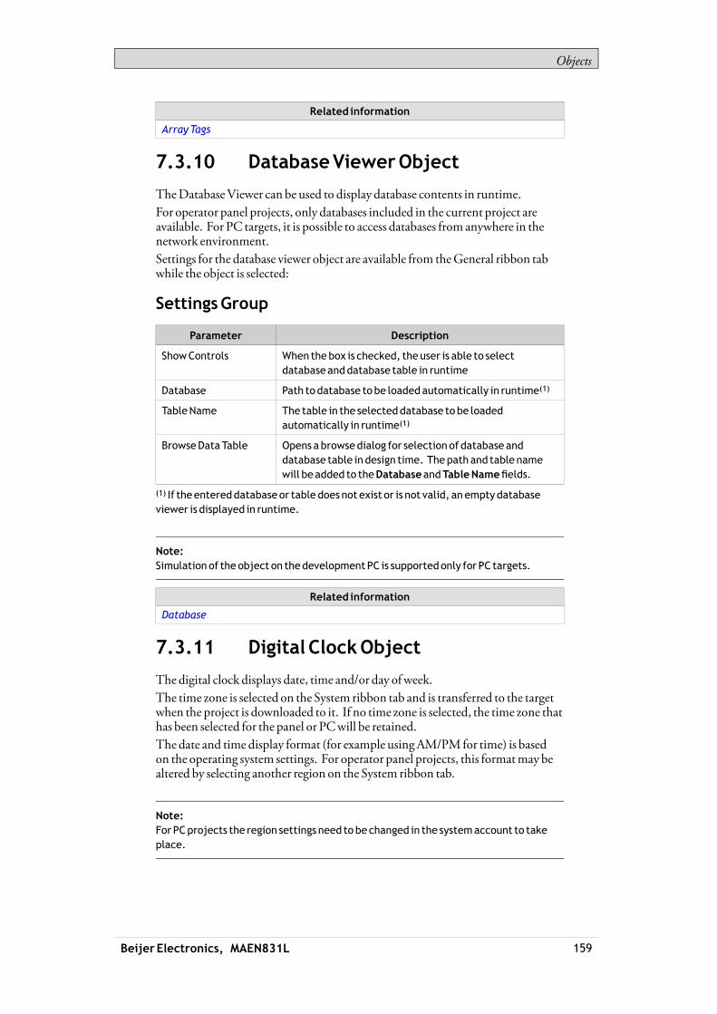
Objects
Related information
ArrayTags
7.3.10 DatabaseViewerObject
TheDatabaseViewer can be used to display database contents in runtime.For operator panel projects, only databases included in the current project areavailable. For PC targets, it is possible to access databases from anywhere in thenetwork environment.Settings for the database viewer object are available from theGeneral ribbon tabwhile the object is selected:
SettingsGroup
Parameter Description
ShowControls When thebox is checked, theuser is able to selectdatabaseanddatabase table in runtime
Database Path todatabase tobe loadedautomatically in runtime(1)
TableName The table in the selecteddatabase tobe loadedautomatically in runtime(1)
BrowseDataTable Opens abrowsedialog for selectionof database anddatabase table indesign time. Thepath and table namewill beadded to theDatabaseandTableNamefields.
(1) If theentereddatabaseor table doesnot exist or is not valid, an emptydatabaseviewer is displayed in runtime.
Note:Simulation of the object on thedevelopmentPC is supportedonly for PC targets.
Related information
Database
7.3.11 Digital ClockObject
The digital clock displays date, time and/or day ofweek.The time zone is selected on the System ribbon tab and is transferred to the targetwhen the project is downloaded to it. If no time zone is selected, the time zone thathas been selected for the panel or PCwill be retained.The date and time display format (for example usingAM/PM for time) is basedon the operating system settings. For operator panel projects, this formatmay bealtered by selecting another region on the System ribbon tab.
Note:For PCprojects the region settings need to bechanged in the systemaccount to takeplace.
Beijer Electronics, MAEN831L 159

Objects
Related information
Date,Time,andRegionGroup
DisplayFormatGroup
Parameter Description
DateAndTime/Date/Time Selectionof date and timecomponents
ShowDayofWeek Whenchecked,dayofweek is displayed
ShowSeconds Whenchecked, seconds aredisplayed
7.3.12 LinearMeterObject
TheLinearMeter represents a numeric value, and displays the value of a connectedtag.Different styles can be used to change the graphical profile of themeter, and also ifthemeter is to be horizontal or vertical.
Linearmeters inClassicHorizontal style andEclipse Vertical style
Settings for themeter object are available from theGeneral ribbon tabwhile theobject is selected:
ValueScaleGroup
Parameter Description
MinValue/MaxValue Start/end valueof scale
These values can consist of onedecimal digit.
Major Ticks Numberof labeled scalemarks on themeter
Minor Ticks Numberof scale ticks between twoadjacentmajor ticks
Beijer Electronics, MAEN831L 160

Objects
StyleGroup
Parameter Description
Style Predefinedgraphical styles for themeter. The smallerstyles are intended inparticular to allow full visibility inthe smaller operator panels.
Appearance Theappearanceof themeter; horizontal or vertical
Tag/SecurityGroup
Parameter Description
Select Tag Connection to a tag fromthe tags configuration page
Select SecurityGroups Allows limiting access of the object basedon securitygroups. If left empty, theobject canbeaccessedbyanyone.
SelectVisibility Configuration of visibility:
Default: Thevisibility specifiedon theGeneral tabof theSecurityManager is used.
Disabled: Theobject is disabled for userswith insufficientaccess rights
Hidden: Theobject is invisible for userswith insufficientaccess rights
Normal: Theobject looks normal also for userswithinsufficient access rights
VisibilityGroup
Parameter Description
Transparent Makes theobject transparent; only indicator bar and scalewill be visible
Scale Whenunchecked, the scale color of themeter ismadetransparent. Scale color and indicator color are set fromOtherColors on theFormat tab.
7.3.13 Multi PictureObject
TheMulti Picture object allows using a set of pictures as an object. The pictureschange in runtime depending on intervals of a tag value.Pictures can be imported to the project by browsing the hard disk for graphic files.Imported pictures are added to the Project Pictures folder in theComponentLibrary.Settings for theMulti Picture object are available from theGeneral ribbon tabwhile the object is selected:
Beijer Electronics, MAEN831L 161
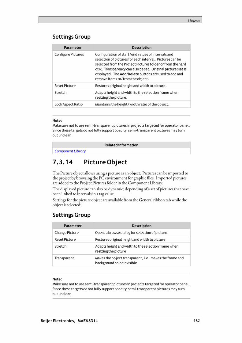
Objects
SettingsGroup
Parameter Description
ConfigurePictures Configuration of start/endvalues of intervals andselectionof pictures for each interval. Pictures canbeselected fromtheProject Pictures folder or fromtheharddisk. Transparency canalso be set. Original picture size isdisplayed. TheAdd/Deletebuttons areused to addandremove items to/fromtheobject.
Reset Picture Restores original height andwidth topicture.
Stretch Adapts height andwidth to the selection framewhenresizing thepicture.
LockAspectRatio Maintains the height/width ratio of theobject.
Note:Make surenot to use semi-transparent pictures in projects targeted for operator panel.Since these targets donot fully support opacity, semi-transparent picturesmay turnout unclear.
Related information
Component Library
7.3.14 PictureObject
ThePicture object allows using a picture as an object. Pictures can be imported tothe project by browsing the PC environment for graphic files. Imported picturesare added to the Project Pictures folder in theComponent Library.The displayed picture can also be dynamic; depending of a set of pictures that havebeen linked to intervals in a tag value.Settings for the picture object are available from theGeneral ribbon tabwhile theobject is selected:
SettingsGroup
Parameter Description
ChangePicture Opens abrowsedialog for selectionof picture
Reset Picture Restores original height andwidth topicture
Stretch Adapts height andwidth to the selection framewhenresizing thepicture
Transparent Makes theobject transparent, i.e. makes the frameandbackgroundcolor invisible
Note:Make surenot to use semi-transparent pictures in projects targeted for operator panel.Since these targets donot fully support opacity, semi-transparent picturesmay turnout unclear.
Beijer Electronics, MAEN831L 162

Objects
Related information
Component Library
7.3.15 RollerPanelObject
TheRoller Panel object is used to display predefined texts for certain tag values.Settings for theRoller Panel object are available from theGeneral ribbon tabwhilethe object is selected:
SettingsGroup
Parameter Description
Title Set the title for theRoller Panel
TitleVisible Determines if the title is visible or not
Loop Scroll Determines if the valueswill looparoundor not
DisableOperator Input Determines if theRoller Panel is editable or not
TouchSettingsGroup
Parameter Description
Scroll Sensitivity Set the sensitivity of the scroll
Scroll Friction Set the frictionof the scroll
TextGroup
Parameter Description
ConfigureTexts Opens theConfigureTexts dialog
ConfigureTextDialog
TheConfigureTexts dialog contains the following properties:
Parameter Description
Text The text tobedisplayed for the item
Start Value The starting value forwhen this itemshouldbe selected
EndValue Theending value forwhen this itemshouldbe selected
RollerPanelDynamics
It is also possible to set dynamics, i.e. tag dependent values for theRoller Panelproperties. These can be found in theDynamics tab in the ribbon bar.
Related information
DynamicsRibbonTab
Beijer Electronics, MAEN831L 163

Objects
7.3.16 SliderObject
The Slider can be used to adjust a numeric value. The slider sets a value to aconnected tag. If the tag value changes for other reasons, the slider control handlewill show the actual value in runtime.
Sliders inChrome andEclipseHorizontal styles, andVintage Vertical style
Settings for the slider object are available from theGeneral ribbon tabwhile theobject is selected:
ValueScaleGroup
Parameter Description
MinValue/MaxValue Start/end valueof scale
These values can consist of onedecimal digit.
Major Ticks Numberof labeled scalemarks on the slider
Minor Ticks Numberof scale ticks between twoadjacentmajor ticks
StyleGroup
Parameter Description
Style Predefinedgraphical styles for the slider. The smallerstyles are intended inparticular to allow full visibility inthe smaller operator panels.
Appearance Theappearanceof the slider; horizontal or vertical
Beijer Electronics, MAEN831L 164

Objects
Tag/SecurityGroup
Parameter Description
Select Tag Connection to a tag fromthe tags configuration page
Select SecurityGroups Allows limiting access of the object basedon securitygroups. If left empty, theobject canbeaccessedbyanyone.
SelectVisibility Configuration of visibility:
Default: Thevisibility specifiedon theGeneral tabof theSecurityManager is used.
Disabled: Theobject is disabled for userswith insufficientaccess rights
Hidden: Theobject is invisible for userswith insufficientaccess rights
Normal: Theobject looks normal also for userswithinsufficient access rights
VisibilityGroup
Parameter Description
Transparent Makes theobject transparent
Scale Whenunchecked, the scale color of the slider ismadetransparent. Scale color and indicator color (color of thehandle) are set fromOtherColors on theFormat tab.
7.3.17 TextObject
TheText object is used to display read-only information for the operator. Thedisplayed text can be static, or linked to intervals in a tag value that containdifferent strings. The text object can also be set to dependdirectly on a tag valueusing theGeneral control on theDynamics ribbon tab.Settings for the text object are available from theGeneral ribbon tabwhile theobject is selected:
TextGroup
Parameter Description
Text Text that theobject displays
Multiline Lets the text run overmore thanone line, using [Enter].
Confirm the text entrybypressing [Ctrl] + [Enter].
WordWrap Wraps the text tofit thewidth of theobject. Not availableif Autosize is selected.
ConfigureTexts Links thedisplayed text to a tag. TheTextfield value isshown if the selected tag is notwithin the set limits.
Beijer Electronics, MAEN831L 165

Objects
Parameter Description
Auto StretchFont Resizes the font tofit theheight of theobject. Notavailable if Autosize is selected.
Auto Size Resizes the object according to the size of thedefault textstring lengthand font size. Default setting for the textobject.
TextAlignmentGroup
Parameter Description
Horizontal /Vertical Adjusts the text in theobject horizontally or vertically.Not available if Autosize is selected.
7.3.18 TouchComboBoxObject
TheTouchComboBox object is used to create text selections from a drop-downlist.Settings for theTouchComboBox object are available from theGeneral ribbontabwhile the object is selected:
SettingsGroup
Parameter Description
Auto Size ItemHeight TheTouchComboBoxwill ignore the ItemHeight value andsize the values automatically
ItemHeight Set the height of the individual items in theTouchComboBox
ArrowBoxWidth Set thewidthof theArrowBox
ScrollBarWidth Set thewidthof the scroll bar
TextGroup
Parameter Description
ConfigureTexts Opens theConfigureTexts dialog
ConfigureTextDialog
TheConfigureTexts dialog contains the following properties:
Parameter Description
Text The text tobedisplayed for the item
Start Value The starting value forwhen this itemshouldbe selected
EndValue Theending value forwhen this itemshouldbe selected
Beijer Electronics, MAEN831L 166
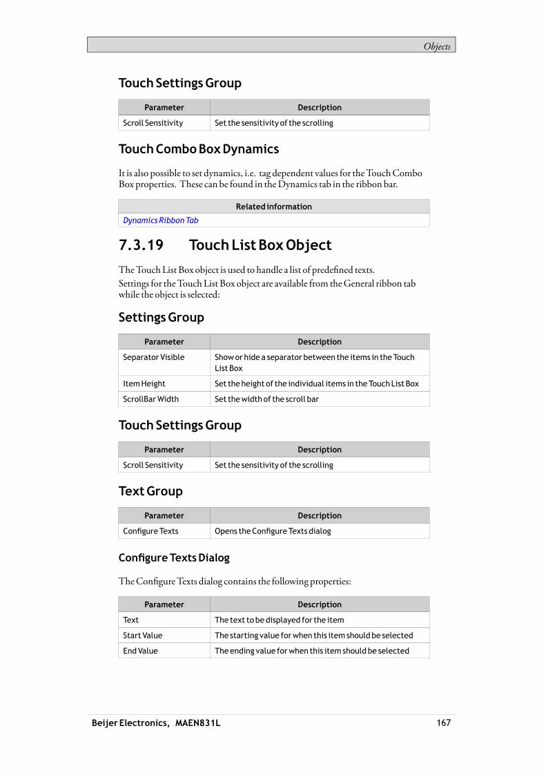
Objects
TouchSettingsGroup
Parameter Description
Scroll Sensitivity Set the sensitivity of the scrolling
TouchComboBoxDynamics
It is also possible to set dynamics, i.e. tag dependent values for theTouchComboBox properties. These can be found in theDynamics tab in the ribbon bar.
Related information
DynamicsRibbonTab
7.3.19 TouchListBoxObject
TheTouchList Box object is used to handle a list of predefined texts.Settings for theTouchList Box object are available from theGeneral ribbon tabwhile the object is selected:
SettingsGroup
Parameter Description
Separator Visible Showor hide a separator between the items in theTouchList Box
ItemHeight Set the height of the individual items in theTouchList Box
ScrollBarWidth Set thewidthof the scroll bar
TouchSettingsGroup
Parameter Description
Scroll Sensitivity Set the sensitivity of the scrolling
TextGroup
Parameter Description
ConfigureTexts Opens theConfigureTexts dialog
ConfigureTextsDialog
TheConfigureTexts dialog contains the following properties:
Parameter Description
Text The text tobedisplayed for the item
Start Value The starting value forwhen this itemshouldbe selected
EndValue Theending value forwhen this itemshouldbe selected
Beijer Electronics, MAEN831L 167

Objects
TouchListBoxdynamics
It is also possible to set dynamics, i.e. tag dependent values for theTouchList Boxproperties. These can be found in theDynamics tab in the ribbon bar.
Related information
DynamicsRibbonTab
7.3.20 TrendViewerObject
Trend viewers are used to display values of connected tags. Trend viewer curvesrepresent tag values over time. A trend viewer object can show any number oftrend viewer curves.
Note:A largenumber of trend viewerpens and short sampling intervalsmayaffectcommunicationperformance.
Related information
TrendViewer
CurvesGroup
CommunicationPerformance
7.4 MediaControls
Themedia controls are used to displaymedia files, pdf files andweb pages inruntime. The followingmedia controls are described:
MediaPlayerObject PDFViewerObject WebBrowserObject
7.4.1 MediaPlayerObject
Media files can be added to themedia player object, which allows selecting,starting and stopping the files in runtime. For operator panels, files in .mpeg1 and.wmv format are supported. The files are added to theComponent Library.
Note:WindowsMediaPlayer 10or later is required.
Beijer Electronics, MAEN831L 168

Objects
BrowseFoldersGroup
Parameter Description
Project Files Default option for browsing. Theprojectfiles are listedin theComponent Library. At least oneof the folders hastobechosen.
ExternalMemoryCard Select this option for browsing if projectfiles are placedonanexternalmemory card. At least oneof the folders hastobechosen.
SettingsGroup
Parameter Description
Media Source Select amediafile to add to themediaplayer, from theprojectfiles folder or bybrowsing thePC
Note:Theobject is not supportedon iXTxA targets. Simulationof theobject on thedevelopmentPC is supportedonly for PC targets.
Note:Connecting a tag to aMedia PlayerObjectwill cause themediaplayer to try toplay amedia clipwith a name that corresponds to the tag’s value, ignoring the configuredMedia Sourceparameter.
Scripting to theMediaPlayerObject
When scripting to theMedia Player object, the name of the currentmedia file hasto be stated, for example:MediaPlayer1.Source = “Bear.wmv”;Prior to running the script, themedia file has to be addedmanually to the ProjectFiles folder. When the script is executed, the file will be copied to the outputdirectory.Events for themedia player can be used, for example:MediaPlayer1.Play();
Related information
Component Library
7.4.2 PDFViewerObject
PDFfiles can be displayed in runtime using the PDFviewer object. The addedfiles are available from theComponent Library.
Beijer Electronics, MAEN831L 169

Objects
Note:AdobeReader 9or 9.5 is required.
BrowseFoldersGroup
Parameter Description
Project Files Default option for browsing. Theprojectfiles are listedin theComponent Library. At least oneof the folders hastobechosen.
ExternalMemoryCard Select this option for browsing if projectfiles are placedonanexternalmemory card. At least oneof the folders hastobechosen.
SettingsGroup
Parameter Description
PDFFile Select aPDFfile to add to thePDF viewer, fromtheprojectfiles folder or bybrowsing thePC
Buttons Selectwhichbuttons tomakeavailable in runtime
In an operator panel, all PDFfiles in the project files folderwill be available forselection in runtime, if theOpen button is checked.
Note:Whenusing aPDFviewerobject in apopup screen, only thedefault style for thepopupscreen is supported.
Note:Theobject is not supportedon iXTxA targets. Simulationof theobject on thedevelopmentPC is supportedonly for PC targets.
Related information
Component Library
PopupScreen
AdobeReader notRecognized
7.4.3 WebBrowserObject
Webpages can be displayed using theweb browser. It is possible to set up thewebbrowserwith regular web browsing functionality, with selection ofweb addressesin a list or input via the virtual keyboard. It is also possible to allow showing certaindefinedweb pages only, or a localHTM/HTMLfile.
Note:Microsoft Internet Explorer 9 or later is required.
Beijer Electronics, MAEN831L 170
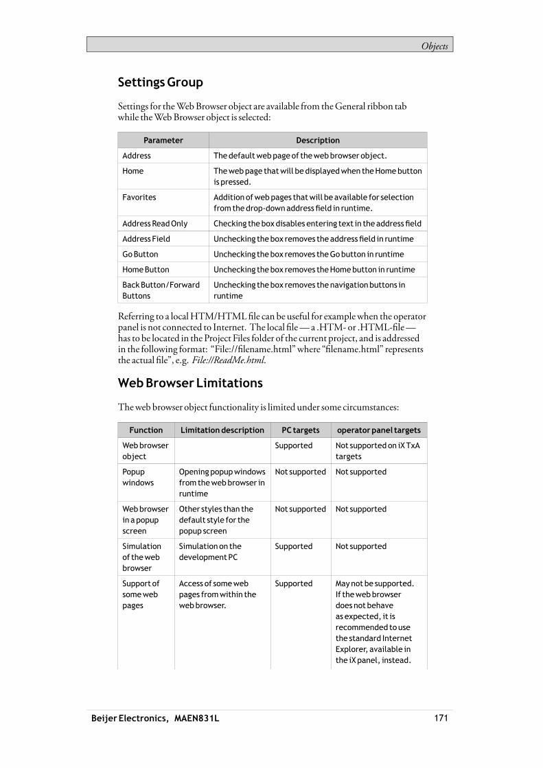
Objects
SettingsGroup
Settings for theWebBrowser object are available from theGeneral ribbon tabwhile theWebBrowser object is selected:
Parameter Description
Address Thedefaultwebpageof thewebbrowser object.
Home Thewebpage thatwill bedisplayedwhen theHomebuttonis pressed.
Favorites Addition ofwebpages thatwill beavailable for selectionfromthedrop-downaddressfield in runtime.
Address ReadOnly Checking theboxdisables entering text in theaddressfield
Address Field Unchecking thebox removes theaddressfield in runtime
GoButton Unchecking thebox removes theGobutton in runtime
HomeButton Unchecking thebox removes theHomebutton in runtime
BackButton/ForwardButtons
Unchecking thebox removes thenavigationbuttons inruntime
Referring to a localHTM/HTMLfile can be useful for examplewhen the operatorpanel is not connected to Internet. The local file—a .HTM-or .HTML-file—has to be located in the Project Files folder of the current project, and is addressedin the following format: “File://filename.html”where “filename.html” representsthe actual file”, e.g. File://ReadMe.html.
WebBrowserLimitations
Theweb browser object functionality is limited under some circumstances:
Function Limitationdescription PC targets operatorpanel targets
Webbrowserobject
Supported Not supportedon iXTxAtargets
Popupwindows
Openingpopupwindowsfromthewebbrowser inruntime
Not supported Not supported
Webbrowserin apopupscreen
Other styles than thedefault style for thepopup screen
Not supported Not supported
Simulationof thewebbrowser
Simulationon thedevelopmentPC
Supported Not supported
Support ofsomewebpages
Access of somewebpages fromwithin thewebbrowser.
Supported Maynot be supported.If thewebbrowserdoesnot behaveas expected, it isrecommended tousethe standard InternetExplorer, available inthe iXpanel, instead.
Beijer Electronics, MAEN831L 171

Objects
Function Limitationdescription PC targets operatorpanel targets
The standard InternetExplorer canbe startedusing theRunactionandexecuting theiesample.exefile.
Related information
PopupScreen
7.5 Special Controls
The special controls are used to create attractive navigation facilities in runtime.
Navigation List BoxObject ScreenCarouselObject
7.5.1 NavigationList BoxObject
Screennavigation using theNavigation List Box object is performed viathumbnails, and scripting can be used for advanced functionality.
Note:Theobject is supportedonly for iXTxCandPC targets.
GeneralGroup
Parameter Description
Orientation Select horizontal or vertical orientation for runtime scrolling.
Scroll Tolerance Defines tolerance of pressing the touch screen (or scrollingwith the cursor) slightly outsideof anavigation list box item inruntimebefore thenavigation is actually carriedout.
ItemSettingsGroup
Parameter Description
Configure Items Definitionof items included in thenavigation list box object;seebelow.
Height/Width Sizeof the items in thenavigation list box.
Margin Marginbetweennavigation list box items.
BorderWidth Widthof navigation list box itemborders.
CornerRadius Corner radius of navigation list box items.
ShowText Selection ofwhether to show text belownavigation list boxitems.
Beijer Electronics, MAEN831L 172

Objects
The individual items in the navigation list box object are handled by clickingConfigure Items. Use theAdd andDeletebuttons to add and remove itemsto/from the navigation list box.
Parameter Description
Picture Selection of picture bybrowsing thePCenvironment or amongtheprojectfiles.
Screen Selection of screen tonavigate to.
Script Info Optional text to serveas a reminder if scripts are used.
Text Text displayedunder eachnavigation list box item.
Only visible if ShowText is checkedunder ItemSettings.
Use the up and down arrows to facilitate reorganizing of navigation list box items.
Related information
Script
7.5.2 ScreenCarouselObject
Screennavigation using the ScreenCarousel object is performed via thumbnailsin a 3Dview. The screen carousel can be configured to rotate automatically, oractions can be configured to control screen carousel behavior.
Note:Theobject is supportedonly for iXTxCandPC targets.
Note:If the iXDeveloper systemrequirements for the graphic card arenot fulfilled, thevisualizationof theobjectwill have limitations. Hardwareacceleration is required.
Beijer Electronics, MAEN831L 173

Objects
GeneralGroup
Parameter Description
Number ofVisibleItems
Maximumnumber of visible items.
Scroll Duration (ms) Timeused for an itemtomove to thenext position in thecarousel.
UseReflection Adds a reflecting layout to the object.
Auto Scroll Makes theobject rotate automatically.
ItemSettingsGroup
Parameter Description
Configure Items Definition of items included in the screencarousel object;seebelow.
Height/Width Size of the items in the screencarousel.
Margin Marginbetween screencarousel items.
BorderWidth Widthof screencarousel itemborders.
CornerRadius Corner radius of screen carousel items.
ShowText Selectionofwhether to show text below screencarouselitems.
The individual items in the screen carousel object are handled by clickingConfigure Items. Use theAdd andDeletebuttons to add and remove itemsto/from the screen carousel.
Parameter Description
Picture Selectionof picturebybrowsing thePCenvironment oramong theprojectfiles.
Screen Selectionof screen tonavigate to.
Beijer Electronics, MAEN831L 174

Objects
Parameter Description
Script Info Optional text to serveas a reminder if scripts areused.
Text Text displayedunder each screencarousel item.
Only visible if ShowText is checkedunder ItemSettings.
Use the up and down arrows to facilitate reorganizing of screen carousel items.
Related information
ActionsRibbonTab
7.6 DebugTools
Debug tools are used for troubleshooting andmonitoring.
AlarmDistributorViewerObject
–
7.6.1 AlarmDistributorViewerObject
TheAlarmDistributorViewer is a debug tool, used to display information fromtheAlarmDistributor function.
Related information
AlarmManagement
AlarmDistributorViewer
7.7 WindowsControls
The followingWindows controls are described:
CheckBoxObject ComboBoxObject GroupBoxObject List BoxObject
Progress BarObject
RadioButtonObject
Text BoxObject
–
7.7.1 CheckBoxObject
TheCheckBox object controls a digital tag value. The connected tag gets thevalue 1when the box is checked and the value 0when the box is unchecked.The appearance of the text can be adjusted in the Font group of theHome ribbontab.
Beijer Electronics, MAEN831L 175
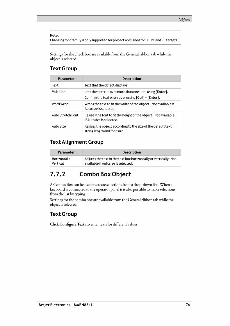
Objects
Note:Changing font family is only supported for projects designed for iXTxCandPC targets.
Settings for the check box are available from theGeneral ribbon tabwhile theobject is selected:
TextGroup
Parameter Description
Text Text that theobject displays
Multiline Lets the text runovermore thanone line, using [Enter].
Confirm the text entrybypressing [Ctrl] + [Enter].
WordWrap Wraps the text tofit thewidthof theobject. Not available ifAutosize is selected.
Auto StretchFont Resizes the font tofit theheight of theobject. Not availableif Autosize is selected.
Auto Size Resizes the object according to the sizeof thedefault textstring lengthand font size.
TextAlignmentGroup
Parameter Description
Horizontal /Vertical
Adjusts the text in the text boxhorizontally or vertically. Notavailable if Autosize is selected.
7.7.2 ComboBoxObject
AComboBox can be used to create selections from a drop-down list. When akeyboard is connected to the operator panel it is also possible tomake selectionsfrom the list by typing.Settings for the combobox are available from theGeneral ribbon tabwhile theobject is selected:
TextGroup
ClickConfigureTexts to enter texts for different values.
Beijer Electronics, MAEN831L 176

Objects
Select a tag, and then clickAdduntil there are enough rows in the table. Enter textsand start values.It is also possible to use script code to control the contents of a combo box.
Example
The following script code relies on the existence of a combobox (ComboBox1)and a set of predefined recipes (“Book” and “TV”).
When the screen opens, the script clears the box andwrites the recipe name stringsin the box. Selection from the combobox triggers loading of a recipe.
Related information
Script
RecipeManagement
7.7.3 GroupBoxObject
TheGroupBox is used to draw a labeled frame around a group of objects.
7.7.4 List BoxObject
TheList Box handles a list of predefined texts.
Beijer Electronics, MAEN831L 177

Objects
TextGroup
ClickConfigureTexts to enter texts for different values.
Select a tag, and then clickAdduntil there are enough rows in the table. Enter textsand start values.It is also possible to use script code to control the contents of a list box.
Example
The following script code includes two objects on Screen1, a button (Button1)and a list box (ListBox1).
When the button is clicked, the script is triggered and a string is written to the listbox and the value of an internal counter (count) is incremented.
Related information
Script
7.7.5 ProgressBarObject
TheProgress Bar displays ameter without numeric scaling, representing an analogvalue. The value can be connected to a tag.The other properties, such as orientation,minimumandmaximumvalues, andmeter color (foreground property) are set in the Property grid.
Beijer Electronics, MAEN831L 178

Objects
Related information
PropertyGrid
7.7.6 RadioButtonObject
ARadioButton controls the value of a connected digital tag.The appearance of the text can be adjusted in the Font group of theHome ribbontab.Settings for the radio button are available from theGeneral ribbon tabwhile theobject is selected:
TextGroup
Parameter Description
Text Text that the object displays
Multiline Lets the text runovermore thanone line, using [Enter].
Confirm the text entry bypressing [Ctrl] + [Enter].
WordWrap Wraps the text tofit thewidthof theobject. Not availableif Autosize is selected.
Auto StretchFont Resizes the font tofit the height of theobject. Not availableif Autosize is selected.
Auto Size Resizes theobject according to the sizeof thedefault textstring length and font size.
TextAlignmentGroup
Parameter Description
Horizontal /Vertical Adjusts the radio button text horizontally or vertically. Notavailable if Autosize is selected.
It is possible to use script code tomake a group of radio buttons enable combinedcontrol of a tag value. Exactly one of the radio buttons is active (set to 1) at anytime. The following example includes 3 radio buttons and a tag of int16 type.
Beijer Electronics, MAEN831L 179

Objects
Radio buttons are grouped based onwhich screen they belong to.
Related information
Script
7.7.7 TextBoxObject
TheTextBox is used to include a boxwithmultiple rows of text.By default, the text can bemodifiedwhen clicking on the box in runtime. Theentered text is not saved in runtime;when the screen changes the valuewill bereset. The text box can also be configured as read-only.Settings for the text box object are available from theGeneral ribbon tabwhile theobject is selected:
Beijer Electronics, MAEN831L 180
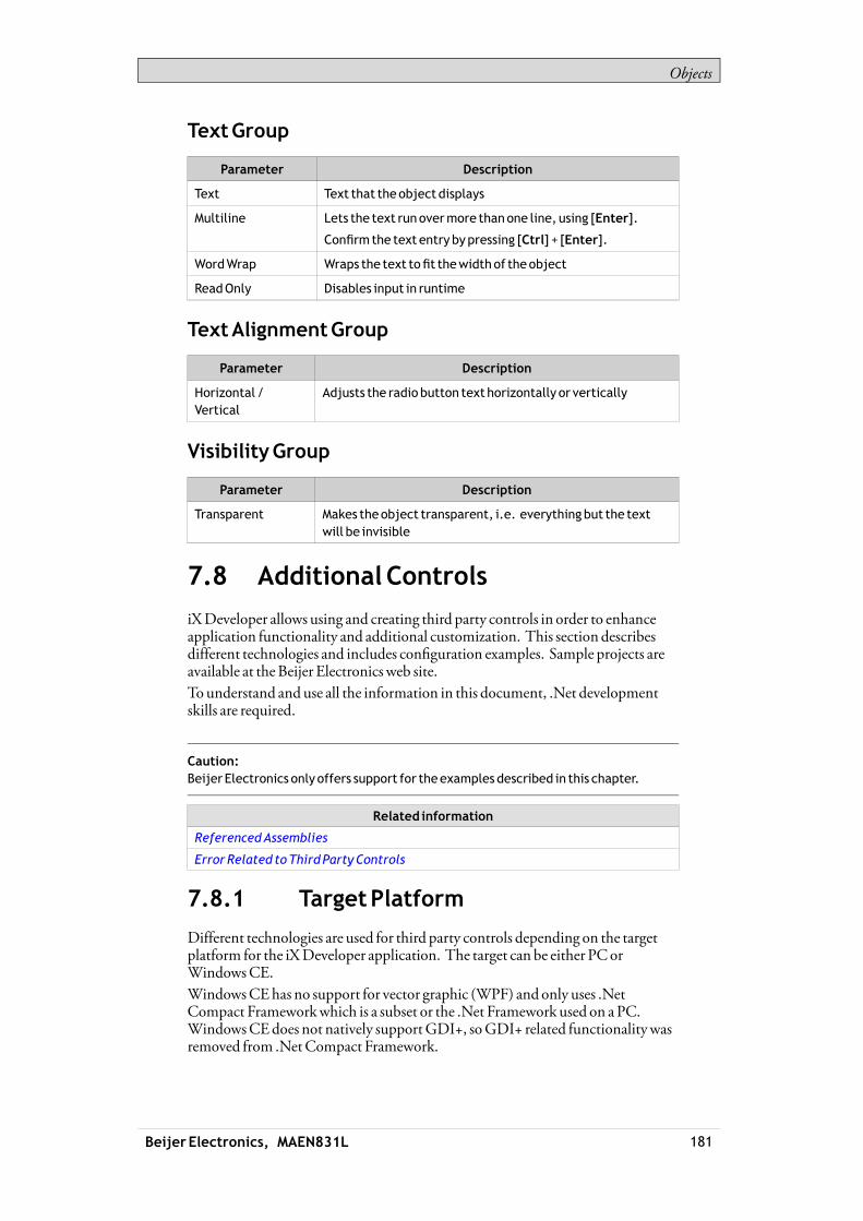
Objects
TextGroup
Parameter Description
Text Text that theobject displays
Multiline Lets the text runovermore thanone line, using [Enter].
Confirm the text entry bypressing [Ctrl] + [Enter].
WordWrap Wraps the text tofit thewidthof theobject
ReadOnly Disables input in runtime
TextAlignmentGroup
Parameter Description
Horizontal /Vertical
Adjusts the radio button texthorizontally or vertically
VisibilityGroup
Parameter Description
Transparent Makes theobject transparent, i.e. everythingbut the textwill be invisible
7.8 AdditionalControls
iXDeveloper allows using and creating third party controls in order to enhanceapplication functionality and additional customization. This section describesdifferent technologies and includes configuration examples. Sample projects areavailable at theBeijer Electronics web site.To understand and use all the information in this document, .Net developmentskills are required.
Caution:Beijer Electronics only offers support for theexamples described in this chapter.
Related information
ReferencedAssemblies
ErrorRelated toThirdPartyControls
7.8.1 TargetPlatform
Different technologies are used for third party controls depending on the targetplatform for the iXDeveloper application. The target can be either PCorWindowsCE.WindowsCEhas no support for vector graphic (WPF) and only uses .NetCompact Frameworkwhich is a subset or the .Net Framework used on aPC.WindowsCEdoes not natively supportGDI+, soGDI+ related functionalitywasremoved from .NetCompact Framework.
Beijer Electronics, MAEN831L 181
Objects
PCTarget
Twodifferent technologies can be used for a PC target:• StandardWindows forms andGDI+• WPF (Windows Presentation Foundation)
WPFuses vector graphics, and the appearance of the control is described inXAML. Since iXDeveloper is aWPF application, it is recommended to useWPFwhen developing customized controls or user controls for a PC target.Controls developed inWPF can bind to a tag value in iXDeveloper, in opposite toWindows forms controls, that cannot be bound to tag values.
WindowsCETarget
WindowsCEonly uses the .NetCompact Framework (a subset or the .NetFramework used on aPC), anddoes not support vector graphics (WPF).WindowsCEdoes not natively supportGDI+, soGDI+ related functionalitywasremoved from the .NetCompact Framework.
Limitations
Some of the limitations regarding third party controls are listed below:• ControlDesigners (a designer class that can extend design time support) are
currently not supported.• TypeConverters in a separate design dll are not supported.• Complex property editing in the property grid is not supported. All complex
properties have to be set up in script.• .NetCompact Framework controls can include design dll and so called
AssmetaData dll to handle attributes that are not supported inWindowsCE.Currently this is not supported by iXDeveloper. Because of this, it isimportant to always test the code on the target platform.
• The Script Editor allows scripting against properties andmethods that are notsupported inWindowsCE.Because of this, it is important to always test thecode on the target platform.
7.8.2 AddingControls to the iXDeveloperToolbox
Third party controls can be added to theObjects toolbox in iXDeveloper,following the steps below:
Caution:Beijer Electronics only offers limited support for thirdparty controls.
Beijer Electronics, MAEN831L 182
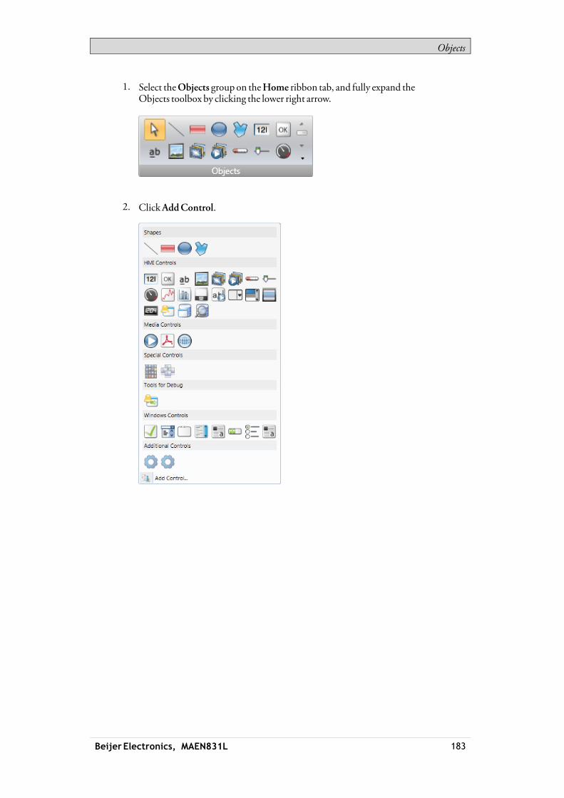
Objects
1. Select theObjects group on theHome ribbon tab, and fully expand theObjects toolbox by clicking the lower right arrow.
2. ClickAddControl.
Beijer Electronics, MAEN831L 183

Objects
3. Select controls to add among the default controls, or clickBrowse to addcustomized controls.
4. ClickOK.The added controls are now available underAdditionalControls in theObjectstoolbox.
7.8.3 Default Controls and InstalledControls
Default controls include controls added by the user and the .Net 4 controlsinstalledwith the .Net Framework.Installed controls include all controls that are installed in theGAC (GlobalAssemblyCache) on your computer.
Note:Thirdparty controls that areused in aproject arenot copied to theproject folder. Thismeans that it is not possible to openaprojectwith thirdparty controls onanotherdevelopmentPCwithout installing the controls. But theapplicationwillwork inruntimeonanother target, since references are copied to theoutput folderwhenbuilding theproject.
7.9 WPFControls
WPF (Windows PresentationFoundation) uses vector graphics, and theappearance of the control is described inXAML. Since iXDeveloper is aWPF
Beijer Electronics, MAEN831L 184

Objects
application, it is recommended to useWPFwhen developing customized controlsor user controls for a PC target. Controls developed inWPF can bind to a tag valuein iXDeveloper.User controls and customcontrols are supported inWPF.
7.9.1 WPFUserControls
AWPFuser control can be described as a composition of different user interfacecontrols. Creating aWPFuser control is similar to creating awindow:• Youhave aXAMLfile andC# class file for a user control.• The class file extends the user control class, adding additional behavior and
properties.• TheXAMLfile encapsulates the composing controls; styles, templates,
animations andwhatever necessary for “Look&Feel”.
Since theWPFuser control is a just composition, it is really easy to create. It doesnot require a lot ofWPFUImodel knowledge.
7.9.2 WPFCustomControls
WPFcustom controls aremore flexible, but aremore complicated than a usercontrol, and require a profoundunderstanding of theWPFuser interfacemodel.• Anumber of certain user interface controls, such as button, progress bar or
speedometer has to be extended.• The appearance of the custom control has to be defined inXAML, as the
custom control itself has no look.
Most of the controls in iXDeveloper are custom controls, whichmakes it possibleto restyle them to various different layoutswithout changing the code files; just theXAML.
A roundedmeter in different styles
7.9.3 Creating aWPFUserControlwithTagConnection
The following example describes how to create aWPFuser control that can beconnected to a tag.The complete code is included at the end of the example.
Beijer Electronics, MAEN831L 185
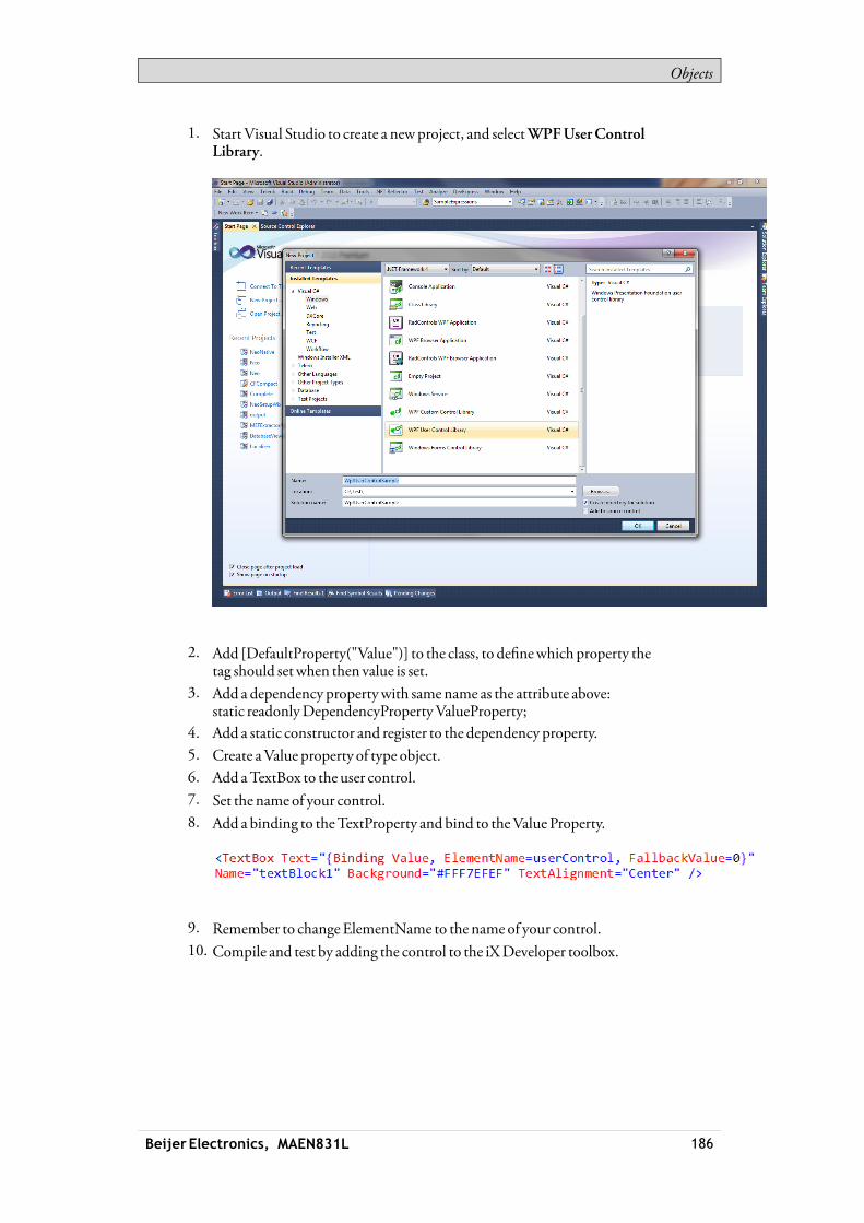
Objects
1. Start Visual Studio to create a newproject, and selectWPFUserControlLibrary.
2. Add [DefaultProperty("Value")] to the class, to definewhich property thetag should set when then value is set.
3. Add a dependency propertywith samename as the attribute above:static readonlyDependencyPropertyValueProperty;
4. Add a static constructor and register to the dependency property.5. Create aValue property of type object.6. Add aTextBox to the user control.7. Set the name of your control.8. Add a binding to theTextProperty and bind to theValue Property.
9. Remember to changeElementName to the name of your control.10. Compile and test by adding the control to the iXDeveloper toolbox.
Beijer Electronics, MAEN831L 186

Objects
Note:Whenanupdate ismade, theexisting controlmust beupdatedunderC:\Users\Public\Documents\Beijer ElectronicsAB\iXDeveloper\Thirdparty\WindowsXP:C:\Documents andSettings\AllUsers\Documents\Beijer ElectronicsAB\iXDeveloper\Thirdparty\
ExampleCode
7.9.4 Creating aWindowsFormsUserControl for aPCTarget
The following example describes how to create aWindows Forms user controldesignated for a PC target.
Beijer Electronics, MAEN831L 187

Objects
Note:Windows Formscontrol objects areplacedon topofWPF control objects in PC targets.
1. Start Visual Studio to create a newproject, and selectWindows FormsControl Library.
2. Add aTextBox and aButton to the design surface.3. AddEventHandler for Button click.4. AddEventHandler forTextBox lost focus.
Beijer Electronics, MAEN831L 188

Objects
5. Add aValue Property and INotifyPropertyChanged implementation:
Beijer Electronics, MAEN831L 189

Objects
6. Use the following code to connect the control to a tag value in iXDeveloper:
The code shows how the value is set on the user control when the tag changesits value, andhow the tag value is changedwhen the user control changes itsvalue.
7.9.5 Creating aWindowsFormsUserControl for aCETarget
The following example describes how to create aWindows Forms user controldesignated for aCE target (a iXTxAor iXTxBoperator panel).
Note:Windows Formscontrol objects areplacedon topof control objects createdwith theiXDeveloper software.
Beijer Electronics, MAEN831L 190
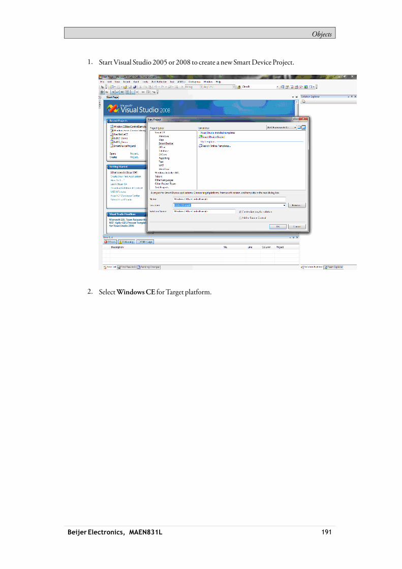
Objects
1. Start Visual Studio 2005 or 2008 to create a newSmartDevice Project.
2. SelectWindowsCE for Target platform.
Beijer Electronics, MAEN831L 191
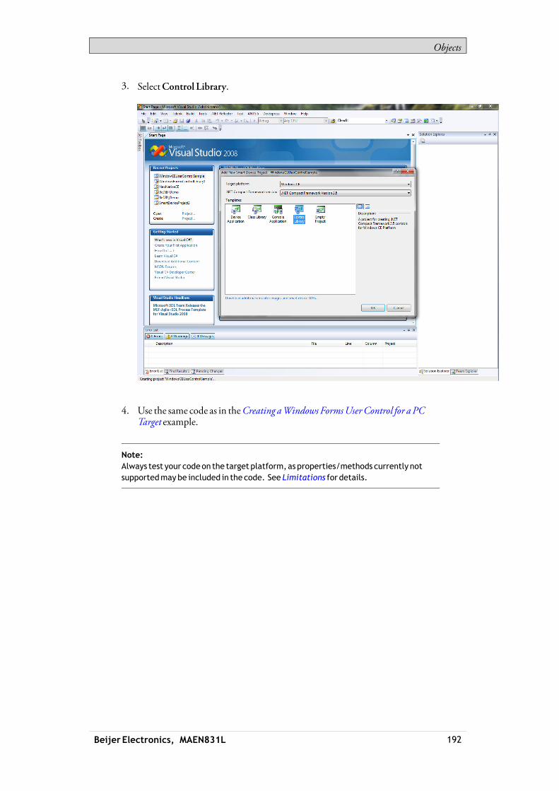
Objects
3. SelectControl Library.
4. Use the same code as in theCreating aWindows FormsUserControl for a PCTarget example.
Note:Always test your codeon the target platform,as properties/methods currently notsupportedmaybe included in the code. See Limitations for details.
Beijer Electronics, MAEN831L 192

RibbonTabs
8 RibbonTabs
Each of the ribbon tabs holds a set of one ormore groups. Each group holds a set ofone ormore controls that are used tomanage screens and functions in a project.
The behavior of the ribbon tabs can be configured to be context dependent usingtheOptions button in the Filemenu.Double-click on any of the ribbon tab headings to collapse the ribbon area. Adouble-click on a ribbon tab, when the ribbon is collapsed, brings back the originalstyle. This can also be changed from the contextmenu of theQuickAccesstoolbar. Tooltips are displayed for all controls on the ribbon tabs. The tooltipoffers a brief description of the selected control.iXDeveloper contains the following ribbon tabs:
HomeRibbonTab
ProjectRibbonTab
SystemRibbonTab
InsertRibbonTab
ViewRibbonTab
DynamicsRibbonTab
General RibbonTab
ActionsRibbonTab
Related information
Options
QuickAccess Toolbar
8.1 HomeRibbonTab
TheHome ribbon tab contains groups of controls for editing screens in theproject:
ClipboardGroup
ScreenGroup
ObjectsGroup
FontGroup
Beijer Electronics, MAEN831L 193

RibbonTabs
FormatGroup
Tag/SecurityGroup
NameGroup
8.1.1 ClipboardGroup
TheClipboard group contains the paste, cut, copy and format painter controls.
Cut
Cuts the selection to the clipboard. Also available from the keyboardwith[Ctrl] + x or from the contextmenu.
Copy
Copies the selection to the clipboard. Also available from the keyboardwith[Ctrl] + c or from the contextmenu.
Paste
Copies the clipboard to the current screen. Also available from the keyboardwith[Ctrl] + v or from the contextmenu.
Note:Text fromacompatible source, e.g. clipboard text,will be converted to aText Boxobjectwhenpasted into a screen.
FormatPainter
TheFormat Painter control is used to copy formatting fromone object to another.This is useful when creating a uniformappearance for objects.To apply formatting to another object:1. Click on an objectwith the desired format and font properties. Click on the
FormatPainter control. Themouse pointer changes to a paintbrush.2. Click on the object to format.The format properties from the first object is applied to the selected object.Format and font properties can be copied between objects of different types, forexample from a rectangle to anHMI control.
Beijer Electronics, MAEN831L 194

RibbonTabs
Note:Modification to anobject using theOtherColors control is not appliedwhenusing theFormatPainter.
Related information
OtherColors
8.1.2 ScreenGroup
The Screen control group contains the add screen, background screen, deletescreen and current language commands. Screens can also be added and deletedfromother controls, such as theNavigationManager and the contextmenu of theProject Explorer.
AddScreen
TheAddScreen command creates a new empty screen that opens for editing.Clicking the lower part of theAdd Screen button shows a selection of screentemplates that are available for selection.
DeleteScreen
TheDelete Screen command removes the current screen from the project, andalso disconnects any associations fromother screens to the removed screen.
Note:Adeleted screencannot be restoredwith theUndo command.
BackgroundScreen
Any screen can be used as background to the current screen.All objects in a background screenwill work as designed in the project application.Objects in a background screenmust be edited in the screen that they residein. Objects in a background screenwill be dimmed in the current screen in thedevelopment environment.
CurrentLanguage
Current language is the language that is being used at the particularmoment thatthe project is designed. Ifmultiple languages are not used in the project, onlyDefault is available.
Beijer Electronics, MAEN831L 195

RibbonTabs
Related information
Screens
LanguageManagement
8.1.3 ObjectsGroup
TheObjects control group contains static anddynamic objects that can be addedto a screen.
Related information
Objects
8.1.4 ObjectVariations
Formany of the objects it is possible to apply a preset style, using theObjectVariations feature. For theButton object and theCircularMeter object there is alarge number of different styles available as default, whereas formost other objectsit is possible to save user-defined styles.
To display theObjectVariationsmenu, click on one of the objects in theObjectsmenu. TheObject Variationsmenu appears to the right of theObjectsmenu,provided that there are some styles available for the selected object.To add user-defined styles in theObject Variationsmenu:1. Select an object to start from.2. Modify the object, using the tools under theHome ribbon tab or theProperty
Grid.3. Select the designed object and right-click to open the contextmenu.4. Select SaveVariations to save themodification.
Beijer Electronics, MAEN831L 196

RibbonTabs
Thenew variationwill appear in theObject Variationsmenuwhen clicking on theobject type it originated from.
Objects supportingSaveVariation
Rectangle Ellipse AnalogNumeric Button
Text LinearMeter Slider CircularMeter
TrendViewer Chart ActionMenu AnimatedLabel
Digital Clock AlarmViewer - -
The object properties are shown in thePropertyGrid. When saving the variationthe following properties are saved (when applicable):
Beijer Electronics, MAEN831L 197

RibbonTabs
Variations saved (whereapplicable)
Color Font Rotation Size
Visibility Security groupsrequired
Audit traildescription
DelayMouse/Touch Input
Visibility onaccessdenied
Opacity Horizontal andvertical alignment
Picture horizontaland verticalalignment
In addition to the general properties listed above, a number of object specificproperties are saved:
Object Property
ActionMenuObject View type
Orientation
AlarmViewerObject Buttonposition
AnalogNumericObject Limit number of characters
Number of characters
Number of decimals
Prefix
Suffix
AnimatedLabelObject Animationdirection
View type
ChartObject Chart type
3Dview
Showheader
Show legend
Showscale
Digital ClockObject Display format
Showseconds
LinearMeterObject Orientation
Scale
Transparency
SliderObject Orientation
Scale
Transparency
TextObject Horizontal alignment
Vertical alignment
TrendViewerObject Major value ticks
Minor value ticks
Rectangle Radius
Effects
Beijer Electronics, MAEN831L 198

RibbonTabs
Note:Features only supported inPCenvironmentmight notworkonotherplatforms.
Related information
Objects
8.1.5 FontGroup
All fonts available in the development PC are available for selectionwhendesigning the project. All fonts used in the project are includedwhen downloadingthe project to the target.
Note:For PCandTxCnon-standard fonts arenot transferredor installed to the target. Installnon-standard fontsmanually on the target.
Note:Thenumber of fonts needs tobeconsideredwhen calculating the total size of aproject.
Note:Thedefault fontTahomadoesnot support Chinese characters in operator panelprojects in runtime. The font has tobechanged to a font that supportsChinesecharacters, e.g. MS Song. Keep inmind that some fonts require a lot of projectmemory.
TheFont group is used to change text style. The text style is defined for thecurrently selected object.
Font andFont Size
Select font from the drop-down list. Use the increase/decrease font size buttons orset a specific font size.
Note:Objects, forwhichAuto StretchFont is selected,will not beaffectedby thesesettings. The font sizewill be autosizedwhen resizing theobject height.
Beijer Electronics, MAEN831L 199

RibbonTabs
Style andColor
An italic, underlined or bold style can be selected for the text. The style staysregular if all the boxes are left unchecked. Use the FontColor drop-down list toset the color of the text.
8.1.6 FormatGroup
TheFormat group controls the color and position of a selected object. Predefinedquick styles offer selection of uniform appearance for different objects. Selectionofmultiple objectsmakes it possible to easily affectmore than one object at thesame time.
Clicking the small arrow in the lower right corner of the Format group displays theshadow, fill and outline propertieswith a number of additional format settings.It is possible to use the Format Painter (in theClipboard group) to copy color andfont properties fromone object andpaste it to another object.
Related information
SelectingMultipleObjects
Arrange
TheArrange control can be used to order, group, resize, align anddistribute screenobjects.
Beijer Electronics, MAEN831L 200

RibbonTabs
OrderObjects
The commands in theOrderObjects group are used to send objects to the front orback of each other.
Command Description
Bring to Front Positions the selectedobject on topof anyoverlappingobjects
Send toBack Positions the selectedobject behindany overlappingobjects
Bring Forward Makes the selectedobject swapplacewith thenearestoverlapping object
SendBackward Makes the selectedobject swapplacewith thenearestobscuredobject
Beijer Electronics, MAEN831L 201

RibbonTabs
Note:TheObject Browser offers an easywayof arranging objects to the front or backof eachother.
Related information
ObjectBrowser
GroupObjects
TheGroupObjects commands are used tomanage selections ofmultiple objects.A grouped object ismoved and treated as one object with respect to formatting andresizing, and can also be stored in theComponent Library for reuse.Any selection of objects on the screen can be grouped.Whenmultiple objects are selected, one object is the primary selection. This isshownwith an orange frame,while other objects in the group have blue frames.Click on any object in the group to change this to the primary selection.A grouped object can be resolved into individual objects using theUngroupcommand. A property thatwas given to the groupwill be kept by each of theobject, provided that the property is applicable.
MakeSameSize
TheMake Same Size commands are used to adjust the size of a group of selectedobjects. The sizewill be determined by the primary selection (the guide object).
PositionObjects
ThePositionObjects commands can be used to align and distributemultipleobjects neatly. Objects can be aligned vertically and horizontally using the primaryselection for the group as guide object. Objects can be alignedwith respect to theircenter (center/middle) or their edges (top/bottom/right/left).
Related information
Component Library
SnapObjects toOtherObjects
Grid
QuickStyles
TheQuick Styles control contains a number of preset visual object color schemesthat can be applied to screen objects.The predefined graphical stylesmake it possible to achieve a uniformappearanceon items likemeters and trend viewers. An object that has a style applied can befurther customized, for examplewith font settings.It is also possible to customize the predefined styles to styles of your ownpreference. The quick styles are not specific to the current project. Theywill beavailable for all iXDeveloper projects.
Beijer Electronics, MAEN831L 202

RibbonTabs
Note:Controls in the Style groupon theGeneral tab canbeused to reshapeobjects such asmeter, slider and trend viewer topredefined styles. These styles arenot the sameasthequick styles.
Related information
FontGroup
OtherColors
Color settings for special properties of an object, for example scale color for ameteror out-of-range validation of an analog numeric object, are available from theOtherColors control.
ShapeFill
TheShape Fill control is used to alter the fill color and gradient of the selectedshape. A previewof the colors in the Shape Fill selectionwindow is displayeddirectly on the object on the screen as the pointer hovers over the different colors.
ShapeOutline
TheShapeOutline control is used to alter the outline color and outlinewidth ofthe selected shape.
ShapeEffects
ShapeEffectsmakes it possible to add bevel style and shadow effects.
Note:Bevel in combinationwithfill color “nofill” is only supported for iXTxCandPC targets.Thebevelwill notbe visible in runtimeonother operatorpanel targets.
8.1.7 Tag/SecurityGroup
Connection to controller tags as well as object access (based on security groups)and visibility are configured from theTag/Security group.
Tag/Security groupwithout andwith selections
Beijer Electronics, MAEN831L 203

RibbonTabs
Parameter Description
Select Tag Connection to a tag fromthe tags configuration page. Tagsmayalso beaddeddirectly, butwill be remain internaluntil connected to a controller tag. Click ... to configureexpressions.
Select SecurityGroups Allows limiting access of the object basedon securitygroups. If left empty, theobject canbeaccessedbyanyone.
SelectVisibility Configuration of visibility:
Default: Thevisibility specifiedon theGeneral tabof theSecurityManager is used
Disabled: Theobject is disabled for userswith insufficientaccess rights
Hidden: Theobject is invisible for userswith insufficientaccess rights
Normal: Theobject looks normal also for userswithinsufficient access rights
Note:Whenaccess rights arenot fulfilled, showing anaccess deniedmessageor openingalogindialog canbeconfiguredusing the security function.
Related information
Expressions
AddingTagsduring Editing
SecurityManagement
8.1.8 NameGroup
All objects and screens are automatically namedwhen they are created. The nameis displayed and can be edited in theName group. Screen names can also be editedin the Project Explorer.The name of an object is a symbolic identifier and is an alphanumeric string,beginningwith a letter. Name strings can contain letters (a-z, A-Z), numbers(0-9), and underscore (‘_’) characters.
Note:Renamingobjects and screens included in scriptswill cause the scripts not to function.
Beijer Electronics, MAEN831L 204

RibbonTabs
Related information
Project Explorer
InvalidNames
8.2 ProjectRibbonTab
TheProject ribbon tab contains a number of project related functions, dividedinto the following groups:
RunGroup
TransferGroup
ProjectGroup
8.2.1 RunGroup
TheRun group enables validation, rebuilding, simulation and debugging of theproject.
Build
The build control validates the script code and compiles the current project.Recompiling the project using theBuild control will result in only the changesbeingmade to project to be recompiled. To fully recompile the project, insteaduse theRebuild control.
Rebuild
The rebuild control validates the script code and recompiles the complete project.
Run
A test of the project can be executed directly on the PC.ClickingRunwill performa validation and start a simulation, if the project can be built. If errors are foundduring validation, an errormessagewill be displayed.During simulation, the projectwill communicate directlywith the configuredcontrollers, provided that the controllers are correctly connected to thedevelopment environment.If there are unused tags in the project, theRun,Build, andRebuild commandswillresult in a notification about this. TheCheckForUnusedTags function can bedisabled or enabled underOptions in theFilemenu.
Beijer Electronics, MAEN831L 205

RibbonTabs
Note:If project build fails, check that theabsolutepath to theproject, including itscomponents, does not exceed260 characters.
Note:Projectsmust be storedon the local harddrive for iXDeveloper tobe able to runorsimulate them.
Simulate
It is also possible to test and run the application on the development PCwithoutconnection to the selected controller, by clickingSimulate. If the project is valid,the simulation is started.
Debug
TheDebug commandwill allow the user to debug scripts in a real c# debuggerwith the possibility to set breakpoints etc. The commandbuilds and checks thecurrent project, and launches the application associatedwith the generated file.The function scans the development PC for an installed debugger. If no debuggeris found, a link for downloading debugger is presented. User preferences for thescript debuggermay be entered underOptions, available from the Filemenu.
Note:Visual Studio 2008 requires SP1 in order for associatedfiles to beopenedautomatically(i.e. using theDebug command).Debuggingof aprojectwith Scriptmodule included is not supportedusingVisual Studio2010.Debuggingof aCEproject is not supportedusingVisual Studio 2010.
Related information
Output
Database
Options
RemovingUnusedTags
8.2.2 TransferGroup
TheTransfer group enables download to operator panel, upload database andexport to folder functions.
Beijer Electronics, MAEN831L 206

RibbonTabs
Note:Timezone, region or daylight saving settingswill not be transferred if these settingshavebeenchangedmanually in thepanel.
Download
TheDownload control sends the project to an operator panel or a PCwith aniXRuntime installation, in the network environment.
Parameter Description
Connected targets Choosea target type to transfer theproject to.
Download Start theproject transfer.
Click the“Downloadall sourcecode ( for laterupload)”checkbox to compress theproject and save it as aZIPfile ontarget.
Click the“Passwordprotected” checkboxandenter apassword toprotect theZIPfile.
Download is supported for TA, PCRT,QTERM, iXTxA, iXTxB,and iXTxC targets, and forPC targetswith a iXRuntimeinstallation.
Click the“Copydownloadedproject toMemoryCard”checkbox to copy thedownloadedproject and the targets IP
Beijer Electronics, MAEN831L 207

RibbonTabs
Parameter Description
settings to thememory card. When theproject is copied tothememory card, it canbeused for restoring theproject(1).
Verify Theverify function enables the user to check if a targetplatformconfiguration is identical to theprojectconfiguration.
Verify is supported for iXTxA, iXTxBand iXTxC targets. Ifgreyedout, please update to latest “Systemprogram”.
Log Show thedatabeing loggedduring thedownloadandverifyprocess.
(1) Supported for panel iXTxA (image version 803orhigher), and iXTxB (imageversion103or higher).
An automatic check is done formismatch between the iXDeveloper version andthe target system versions. All version parameters are considered. If the target isindicated as being incompatiblewith the version of the iXDeveloper that hosts theproject, please update the target with the latest iXRuntime and systemprogramversions.If the target for the download contains newer files or files that don’t exist in theproject, a dialogwill appear prompting forwhichfiles to be kept, overwritten ordeleted.
If the same project is to be downloaded to a panel again, the original datalogger inthe panel will be replaced if any settings have been changed in the datalogger sincethe last download.
Related information
iX panelUpgrade
Downloading aProject toanoperatorpanel or aPCwithaniXRuntime installation
1. Connect the operator panel to the development PCvia anEthernetconnection.
2. ClickDownload.
Beijer Electronics, MAEN831L 208

RibbonTabs
3. The download dialog opens and all panels connected in the network arelistedwith information about IP address and panel type. Select the panel todownload to in the list.
4. Check that the IP address is correct and clickDownload.a. Optional: Click the “Include compressed project” checkbox to compress
the project and save it as aZIPfile.b. Optional: Click the “Passwordprotected” checkbox and enter a password
to protect theZIPfile.c. Optional: Click the “Copy downloadedproject toMemory card”
checkbox to enable SD-card backup of operator panel project andsettings.
The panel responds to a download request by stopping any current project.The panel displays that it is ready for project download. When the download iscompleted, the newproject automatically starts running.The project folder is located at the following path. Only for PC targets!%public%\Documents\Beijer Electronics AB\iXDeveloperRuntime\Project.WindowsXP:Documents andSettings\AllUsers\Documents\BeijerElectronics AB\iXDeveloperRuntime\Project.The panel settings can be controlled from the Servicemenu in the panel.
Note:It is necessary to openTCPport 9999andUDPport 9999 in thefirewall for the runtimePCapplication.
Note:Donot attempt touse theDownload command if a project openedwith the .exefile isopen. Thismight fail to close theproject and the transferwill not be completed.
Note:If Chineseor Korean languages are tobeused in theoperator panel, thenfirewallsinWindowsmust be configured to allowTransferClient.exe full access onall ports,otherwiseproject transfermight fail.
Related information
ServiceMenu
Starting a iXRuntimeproject onaPC
Downloading aProject toanoperatorpanel or aPCwithaniXRuntime installationUsingFTP
Aproject can be loaded to the panel via FTP.To be able to load a project remotelyan external storage device (SDcard orUSB stick)must be attached, and aconfigurationfile namedProjectCopy.configmust be present in the root directoryof the storage device.Set up the configurationfile as follows. Use # for parameters to be ignored.
Beijer Electronics, MAEN831L 209

RibbonTabs
Parameter Description
automatic thedownloadof theproject automatically starts,without anydialogs,whenaprojectfile is loaded tothe storagedeviceand thepanel is rebooted
path "\StorageCard\Project3"
thepath to theproject, ifmultiple projects arestoredon the storagedevice. SDcards use thepath\StorageCard\ anddevices attached toUSBuse\HardDisk\
applyipsettings applies saved IP settings
deletesource deletes the sourcefile from the storagedeviceafterthedownload
deleteconfigfile deletes the configurationfile after thedownload. Ifthe configurationfile is left on the storagedevice it isinitiatedeach time thepanel is rebooted.
Note:This is only supported in the latest released images.
Example:In the followingexample,without displaying anydialogs, theproject found in thefolder Project_5 locatedon theUSB stick is loaded, theproject is deleted fromtheUSBstick, and the configurationfile is deleted. The IP-settings arenotupdated.• automatic• path "\HardDisk\Project_5"• #applyipsettings• deletesource• deleteconfigfile
UploadDatabase
TheUploadDatabase commandwill collect the database fromanoperator panelin the network environment to a file on the development PC.The panel will pauseduring the upload, andwill be started automatically afterwards.The databasemay only be collected froma panel running the same project (i.e.a project with the same name andof the same size) as the current iXDeveloperproject.
CollectingaDatabase fromanoperatorpanel
1. Connect the operator panel to the development PCvia anEthernetconnection.
2. ClickUploadDatabase.3. TheUploadDatabase dialog opens and all panels connected in the network
are listedwith information about IP address and panel type. Select the panel tocollect from in the list.
4. Check that the IP address is correct and clickBackup.5. Select location of the saved database.
Beijer Electronics, MAEN831L 210

RibbonTabs
Export
Exports the project to a folder. The export dialog allows creating a new folder.When exporting the project to Folder the user can selectwhether the panel IPsettings should be set. If yes, theTarget Settings dialog is opened.
Assigning IP Settings is only supported for iXTxA, iXTxB andTA targets.
Exporting aProject toanoperatorpanel or aPCwithaniXRuntime Installation
Aproject can be exported to an operator panel or a PCwith an iXRuntimeinstallation via theExport command. The project can be exported to aUSB stickor, on the condition that a network connection is configured, directly to a folder inthe runtimePC.The project in the runtimePC is started by running the .exe file located in theproject folder.Therewill also be created aTransferClient .exe file, a binaries folder anda configuration file. TheTransferClient is a standalone application fordownloading the exported project to a target. It works in the sameway as theDownload control from inside iXDeveloper. It is possible to view a log for theexport by clicking theLog button on theTransferClientdialog.
Note:It is not recommended tohandle further project transfers fromaPCalreadyusedasa target for export. If additional transfers are tobedone, thenkeepusing the sameexportmethod for all.
Related information
Download
Starting a iXRuntimeproject onaPC
Beijer Electronics, MAEN831L 211
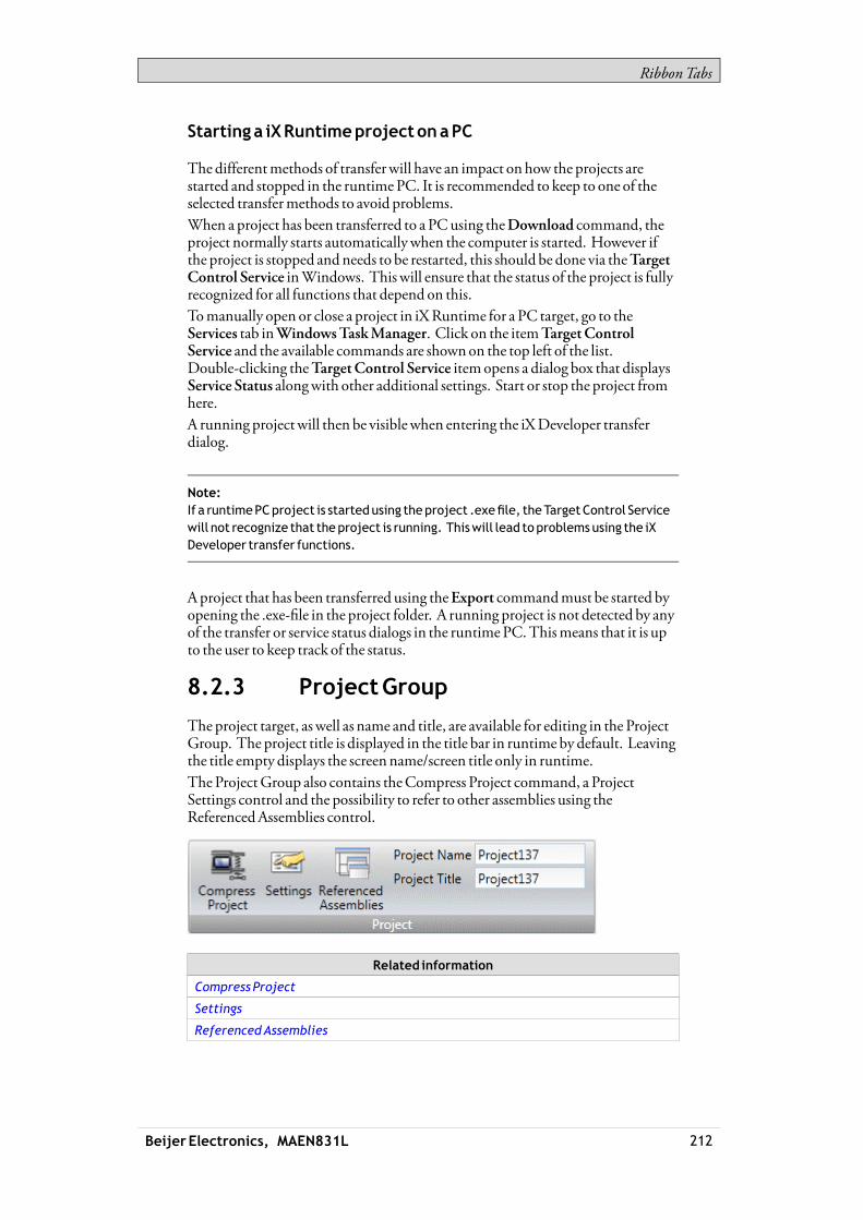
RibbonTabs
Starting a iXRuntimeprojectonaPC
The differentmethods of transferwill have an impact onhow the projects arestarted and stopped in the runtimePC. It is recommended to keep to one of theselected transfermethods to avoid problems.When a project has been transferred to a PCusing theDownload command, theproject normally starts automaticallywhen the computer is started. However ifthe project is stopped andneeds to be restarted, this should be done via theTargetControl Service inWindows. This will ensure that the status of the project is fullyrecognized for all functions that depend on this.Tomanually open or close a project in iXRuntime for a PC target, go to theServices tab inWindowsTaskManager. Click on the itemTargetControlService and the available commands are shownon the top left of the list.Double-clicking theTargetControl Service itemopens a dialog box that displaysService Status alongwith other additional settings. Start or stop the project fromhere.A running projectwill then be visiblewhen entering the iXDeveloper transferdialog.
Note:If a runtimePCproject is startedusing theproject .exefile, theTargetControl Servicewill not recognize that theproject is running. Thiswill lead toproblemsusing the iXDeveloper transfer functions.
Aproject that has been transferred using theExport commandmust be started byopening the .exe-file in the project folder. A running project is not detected by anyof the transfer or service status dialogs in the runtimePC.Thismeans that it is upto the user to keep track of the status.
8.2.3 ProjectGroup
The project target, as well as name and title, are available for editing in the ProjectGroup. The project title is displayed in the title bar in runtime by default. Leavingthe title empty displays the screenname/screen title only in runtime.TheProjectGroup also contains theCompress Project command, a ProjectSettings control and the possibility to refer to other assemblies using theReferencedAssemblies control.
Related information
Compress Project
Settings
ReferencedAssemblies
Beijer Electronics, MAEN831L 212
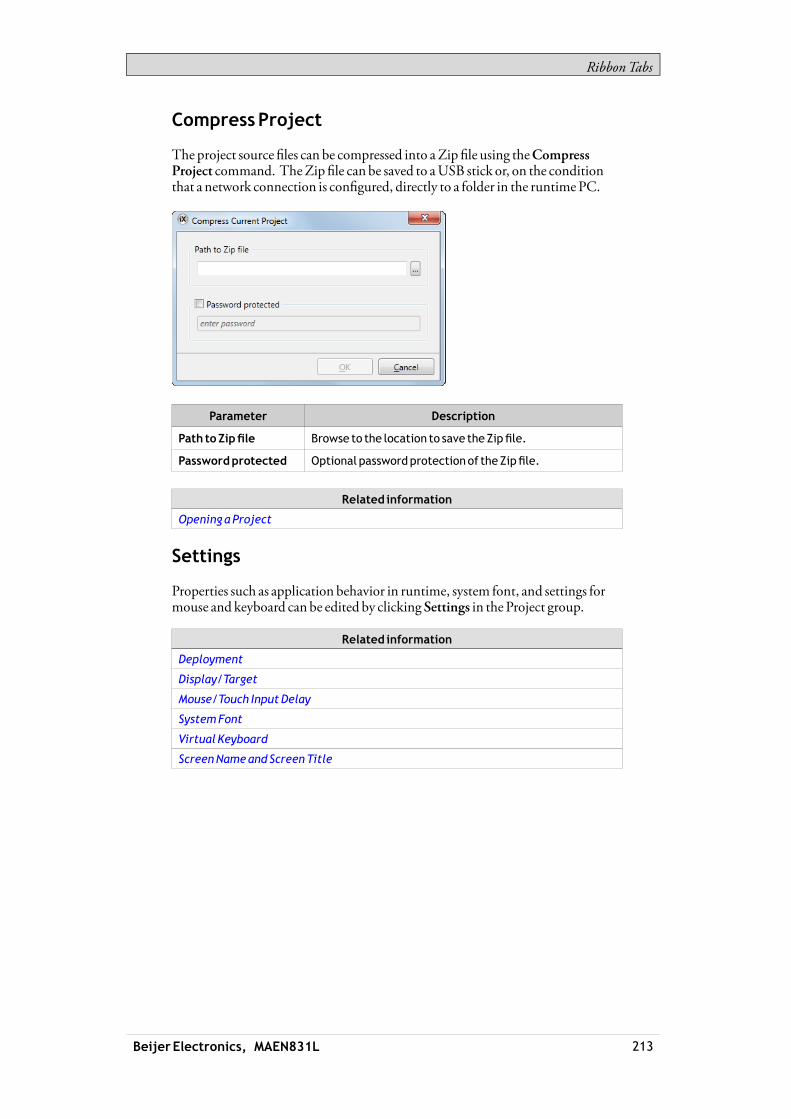
RibbonTabs
CompressProject
The project source files can be compressed into aZip file using theCompressProject command. TheZip file can be saved to aUSB stick or, on the conditionthat a network connection is configured, directly to a folder in the runtimePC.
Parameter Description
Path toZipfile Browse to the location to save theZipfile.
Passwordprotected Optional passwordprotectionof theZipfile.
Related information
Openinga Project
Settings
Properties such as application behavior in runtime, system font, and settings formouse and keyboard can be edited by clicking Settings in the Project group.
Related information
Deployment
Display/Target
Mouse/Touch InputDelay
SystemFont
Virtual Keyboard
ScreenNameandScreenTitle
Beijer Electronics, MAEN831L 213
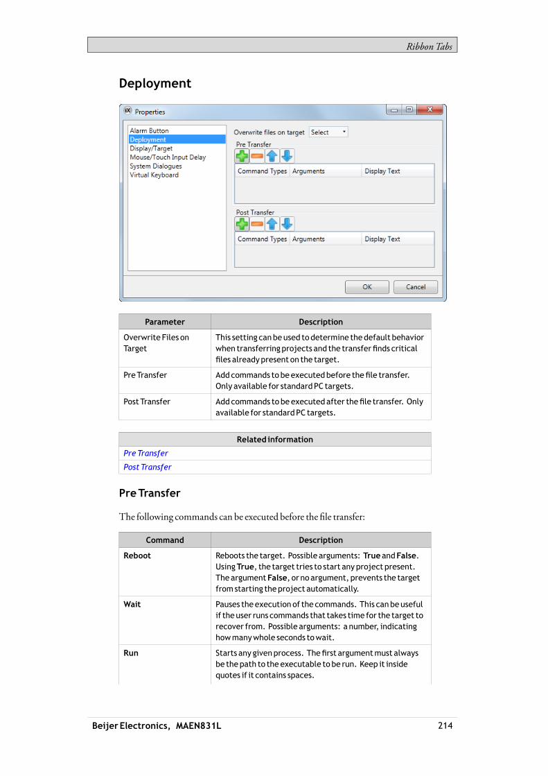
RibbonTabs
Deployment
Parameter Description
Overwrite Files onTarget
This setting canbeused todetermine thedefault behaviorwhen transferringprojects and the transferfinds criticalfiles alreadypresent on the target.
PreTransfer Addcommands tobeexecutedbefore thefile transfer.Only available for standardPC targets.
PostTransfer Addcommands tobeexecutedafter thefile transfer. Onlyavailable for standardPC targets.
Related information
PreTransfer
Post Transfer
PreTransfer
The following commands can be executed before the file transfer:
Command Description
Reboot Reboots the target. Possible arguments: TrueandFalse.UsingTrue, the target tries to start anyproject present.TheargumentFalse, or noargument, prevents the targetfromstarting theproject automatically.
Wait Pauses theexecution of the commands. This canbeusefulif theuser runs commands that takes time for the target torecover from. Possible arguments: a number, indicatinghowmanywhole seconds towait.
Run Starts any givenprocess. Thefirst argumentmust alwaysbe thepath to theexecutable tobe run. Keep it insidequotes if it contains spaces.
Beijer Electronics, MAEN831L 214

RibbonTabs
Command Description
Other arguments:
/p: or -p: areparameters for theprocess to start. Theparametersmust be insidequotes and separatedbyspaces.
/noshellor -noshellmeans that theprocess shouldbe runoutsideof the command shell.
/wd: or -wd: meansworkingdirectory for theprocess torun. If left emptydefaults to activeprojects directory.Theparametersmust be inside quotes.
/wait: or -wait: means that theTargetControlServiceshouldwait until theprocess has exitedbefore continuing.If theprocess does not exit by itself, this argument shouldbe left out.
It is possible to use the followingmacros in conjunctionwith theRun commands:
Macro Description
$projectpath$ Replacedby targetproject folder. If theuser hasdownloadedanexecutable togetherwith theproject andwants to run it, thismacro represents thedestination folder.
Example: "$projectpath$\dbbackup.exe"/p:"backup.bak" -noshell -wait
This runs thedbbackup.exewith the startupargumentbackup.bak, it runs outside the command shelldue to-noshell, and the transfer does not continueuntil theprocess has exited due to -wait.
$startproject$ Registers and starts theproject. The transfer continues.
$finished$ Tells the systemthat the transfer isfinishedandclosesconnections. Theproject does not start. Should onlybeused inPost Transfer.
Note:Only available for iXTxCandPC targets.
PostTransfer
The same commands andmacros as for the PreTransfer can be used, but areexecuted after the file transfer.
Note:Only available for PC targets.
Related information
PreTransfer
Beijer Electronics, MAEN831L 215

RibbonTabs
Display/Target
Parameter Description
NoTitle Bar(1) Displays theprojectwithout title bar in runtime.
Title Bar Displays theprojectwith its title anda set ofminimize,maximizeandclosebuttons in the title bar.
CloseButton Displays theprojectwith its title andaclosebutton in thetitle bar.
Topmost Makes theproject the topmost application in runtime.
Only available for iXTxCandPC targets.
MaximizeOn Startup Makes theprojectmaximized in runtime.
Only available for PC targets.
ScreenSize Screen resolution.
Only available for PC targets.
PanelRotate Displays selected rotation. It is possible to change therotationof thepanel andpanel content by0, 90, 180or 270degrees. Only available for T7A, T10Aand iXTxB targets.
PanelType Displays selected target. It is possible to select anothertarget.
(1) NoTitle Bar cannot beused for popup screens.
Beijer Electronics, MAEN831L 216

RibbonTabs
Related information
ChangingProjectTarget
ChangingProjectTarget
When changing to another target, you can select to automatically resize objects tothe new target size. Different scale factors are used horizontally and vertically, tooptimize conversion to and fromwide screen targets. In this case, the aspect ratioof objects changes.The following items are resizedwith the same factorwhen having selectedautomatic resizing:
Item
Graphical objects
Popup screens
Font(1)
Dynamics size andmove
(1)Aminimumscaled font of 10pixels ensures readability in the smaller operatorpanels.
Not all objects and styles are supported for all project targets. When changing toanother project target, objects and styles that are not supported in the new targetare deleted and are possible to restore. Removed objects are logged, and displayedin awindow after the transformation. The logmay be saved to file. Build files arealways cleaned and project saved after transformation.
Note:Changingback to theprevious target does not restore removedobjects.
Mouse/Touch InputDelay
It is possible to configure a delay ofmouse and touch screen input in runtime.This setting is global and affects all objects forwhichDelayMouse/Touch Inputis selected. The Property grid is used to enable delay ofmouse and touch screeninput for individual objects.
Beijer Electronics, MAEN831L 217
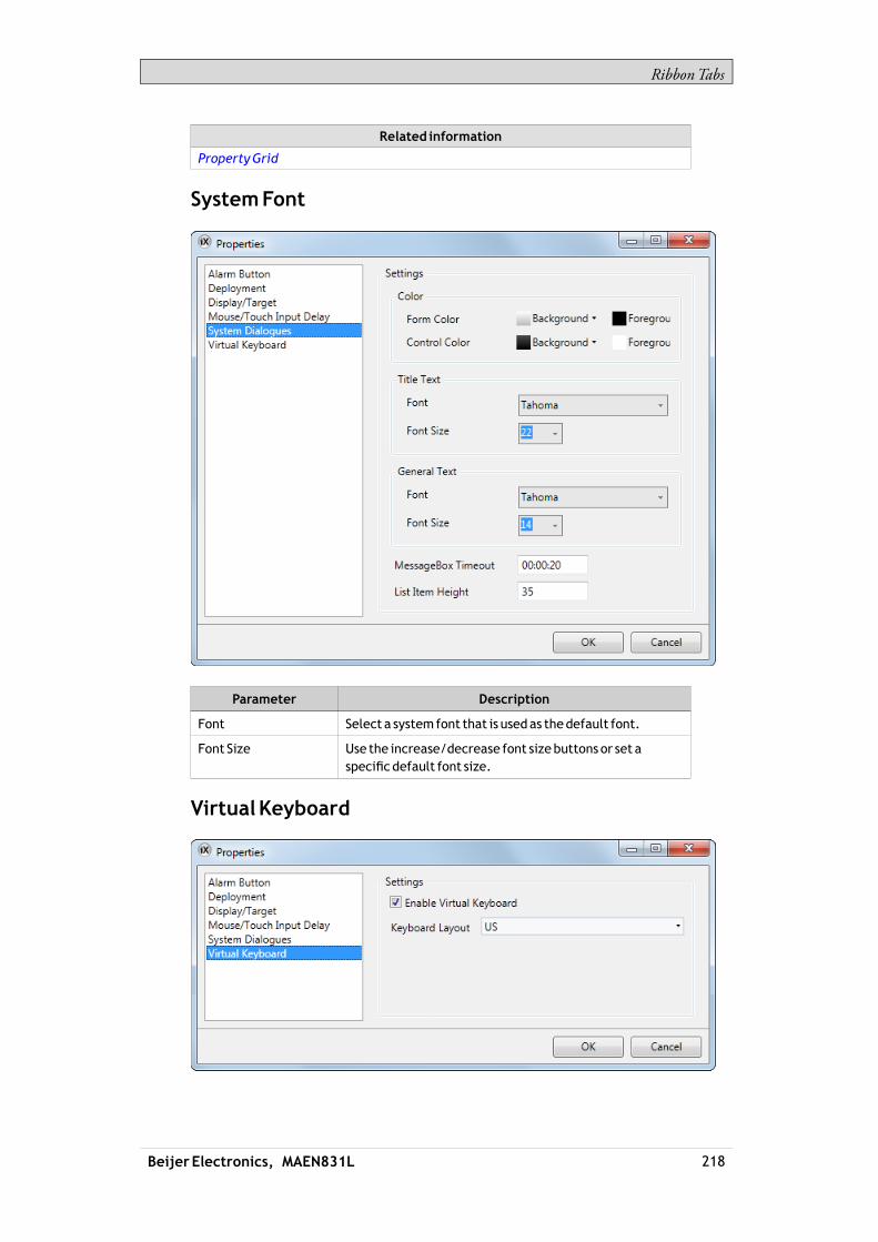
RibbonTabs
Related information
PropertyGrid
SystemFont
Parameter Description
Font Select a systemfont that is usedas thedefault font.
Font Size Use the increase/decrease font sizebuttons or set aspecificdefault font size.
VirtualKeyboard
Beijer Electronics, MAEN831L 218

RibbonTabs
Parameter Description
EnableVirtualKeyboard
Selectwhether a virtual keyboard is to bedisplayedwhenalphanumerical input is needed.
Keyboard Layout The layout of the virtual keyboard.
The virtual keyboard that is displayed in runtime depends on settingsmade fortheMultiple Languages function. If only the default language is used, the projectsettings (above) are used.Some of the virtual keyboards available in iXDeveloper provide a user dictionarywhere all newwords entered are saved. If the built-in login dialog is used, thenpasswords are not saved, but if a custom login dialog is created by scripting, thenpasswordswill be saved.
Related information
LanguageManagement
ReferencedAssemblies
TheReferencedAssemblies commandmakes it possible to refer to your ownor third-party .Net assemblies (.dll). Theirmethods and properties aremadeavailablewhen scripting and are included by the name completion function, in thesameway as for built-in components.1. Click onReferencedAssemblies.2. ClickAdd.3. Browse to the desired dll file in your PC environment and clickOpen.Themethods and properties of the added dll file are now available for scripting.
When referencing your own third-party assembly (.dll file)make sure not to havetwo fileswith the same fully qualified assembly name in the same folder:
Beijer Electronics, MAEN831L 219

RibbonTabs
Example:Youhave thefiles "Iocomp.Instrumentation.CF2005.Ultra.dll" and"Iocomp.Instrumentation.CF2005.Ultra.WindowsCE.asmmeta.dll" in the samefolder. Both have the same fully qualifiedassemblyname (but differentfile names).Trying to add acontrol from thefirst assembly seems towork. Howeverwhen theapplicationuses namespaces in theXAML to locate the correct assembly it picks oneof them,and itmightbeeither of them. If it is thewrongassembly you get amessagesaying that there is an error in theXAML.
8.3 SystemRibbonTab
The System ribbon tab controls system settings. These settings are divided intothe following groups:
Date,Time,andRegionGroup
BuzzerGroup
BacklightGroup
Serial PortsGroup
ServersGroup
OutputDevicesGroup
ServiceMenuGroup
8.3.1 Date,Time, andRegionGroup
National settings aremade in theDate, Time andRegion group.
Select time zone, whether to adjust for daylight saving, and region. If no time zoneis selected, the time zone that has been selected for the panel or PCwill be retained.Choose SNTP time synchronization if the panel clock is to be synchronizedagainst an external SNTP (SimpleNetworkTimeProtocol) server. Enter thename of the SNTP server and the time interval for the synchronization.
Note:TheSNTP time synchronization is supported from iXTxAversion 703 and iXTxB version231.
The date and time display format (for example usingAM/PM for time) is basedon the operating system settings. For operator panel projects, this formatmaybe altered by selecting another region.
Beijer Electronics, MAEN831L 220

RibbonTabs
For a PC the regional settings for date and time display need to be changed in thesystem account to be carried out correctly.1. Go to theControl Panel and selectClock, Language andRegion, then
Region andLanguage.2. Make the regional settings in the dialog box under theFormats tab.3. Then go to theAdministrative tab and clickCopy settings.4. In the dialog box that appears, checkCopy current settings to: Welcome
screen and system accounts, and clickOK.5. Reboot the system to apply the new settings.
Note:iX TxC targets only:If the regional settings are changedonly for theuser accountwithout copying themtothe systemaccount, thenewsettingswill not beappliedwhendownloading aproject,even after a reboot.
8.3.2 BuzzerGroup
Selectwhether to let a key beep soundwhenmaking keyboard input in runtime.Only availablewhen an operator panel is selected as target.
8.3.3 BacklightGroup
Select to automatically turn off the backlight after a certain number of seconds,andwhether to keep the backlight on if a notifierwindow (e.g. alarm indicator orcommunication errormessage) is visible.The backlight settings for a project are saved in the operator panel. Consequently,changes of the backlight settings for the present project will revert to the operatorpanel values. However downloading another project will overwrite the settings.Backlight settings are supported only for operator panel targets. For other targets,theMicrosoftWindows screen savermay be used.
Beijer Electronics, MAEN831L 221
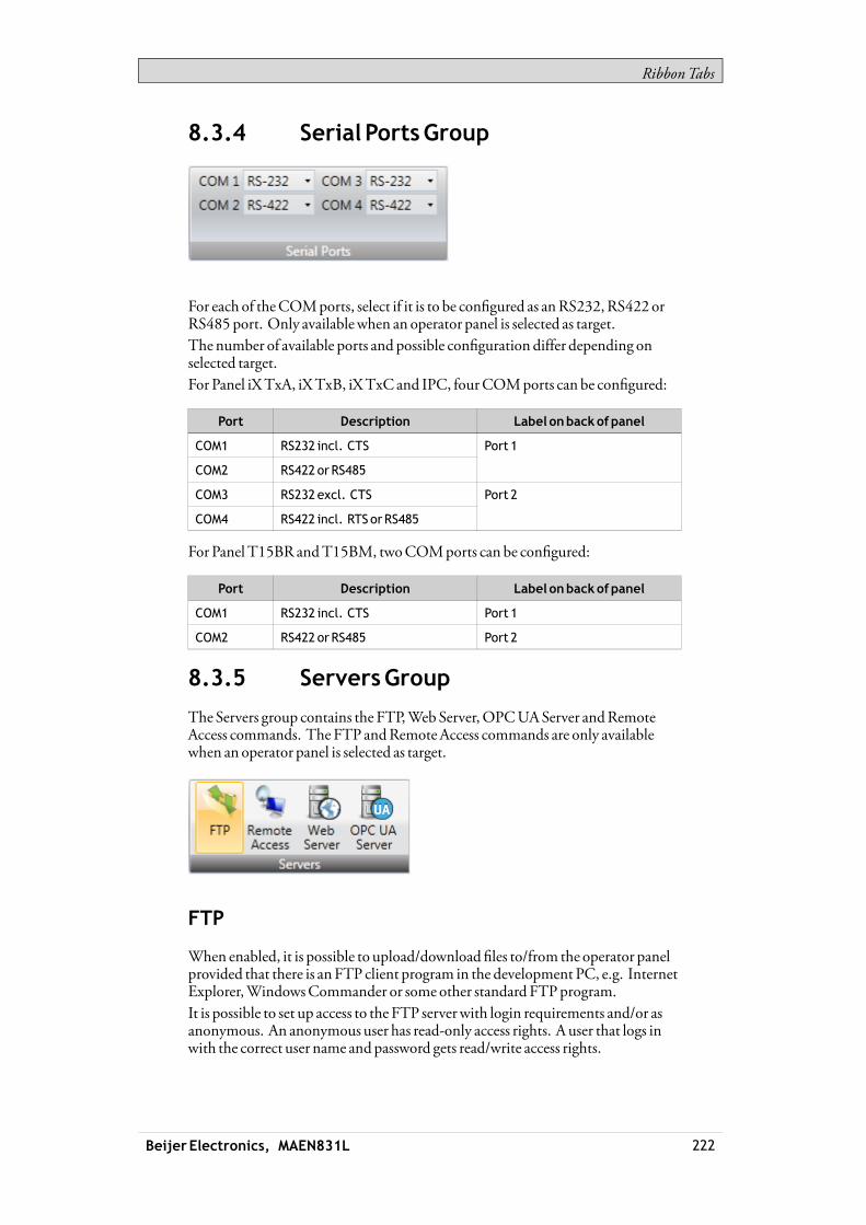
RibbonTabs
8.3.4 Serial PortsGroup
For each of theCOMports, select if it is to be configured as anRS232,RS422 orRS485 port. Only availablewhen an operator panel is selected as target.The number of available ports and possible configuration differ depending onselected target.For Panel iXTxA, iXTxB, iXTxC and IPC, fourCOMports can be configured:
Port Description Label onbackofpanel
COM1 RS232 incl. CTS
COM2 RS422 orRS485
Port 1
COM3 RS232excl. CTS
COM4 RS422 incl. RTS orRS485
Port 2
For Panel T15BR andT15BM, twoCOMports can be configured:
Port Description Label onbackofpanel
COM1 RS232 incl. CTS Port 1
COM2 RS422 orRS485 Port 2
8.3.5 ServersGroup
The Servers group contains the FTP,WebServer,OPCUAServer andRemoteAccess commands. The FTP andRemoteAccess commands are only availablewhen an operator panel is selected as target.
FTP
When enabled, it is possible to upload/download files to/from the operator panelprovided that there is anFTP client program in the development PC, e.g. InternetExplorer,WindowsCommander or some other standard FTPprogram.It is possible to set up access to the FTP serverwith login requirements and/or asanonymous. An anonymous user has read-only access rights. A user that logs inwith the correct user name andpassword gets read/write access rights.
Beijer Electronics, MAEN831L 222
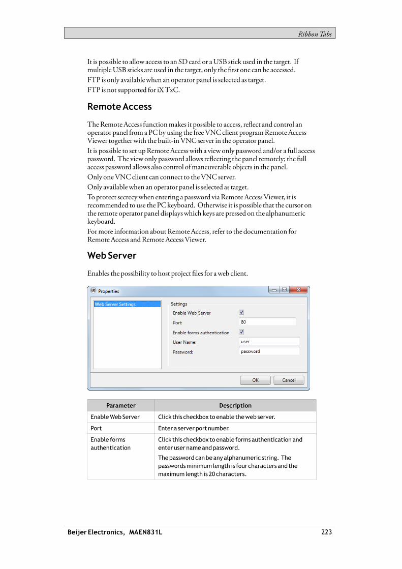
RibbonTabs
It is possible to allow access to an SDcard or aUSB stick used in the target. IfmultipleUSB sticks are used in the target, only the first one can be accessed.FTP is only availablewhen an operator panel is selected as target.FTP is not supported for iXTxC.
RemoteAccess
TheRemoteAccess functionmakes it possible to access, reflect and control anoperator panel from aPCby using the freeVNCclient programRemoteAccessViewer togetherwith the built-inVNC server in the operator panel.It is possible to set upRemote Access with a viewonly password and/or a full accesspassword. The view only password allows reflecting the panel remotely; the fullaccess password allows also control ofmaneuverable objects in the panel.Only oneVNCclient can connect to theVNC server.Only availablewhen an operator panel is selected as target.To protect secrecywhen entering a password viaRemoteAccessViewer, it isrecommended to use the PCkeyboard. Otherwise it is possible that the cursor onthe remote operator panel displayswhich keys are pressed on the alphanumerickeyboard.Formore information aboutRemoteAccess, refer to the documentation forRemoteAccess andRemoteAccessViewer.
WebServer
Enables the possibility to host project files for aweb client.
Parameter Description
EnableWebServer Click this checkbox toenable theweb server.
Port Enter a server port number.
Enable formsauthentication
Click this checkbox toenable formsauthentication andenter user nameandpassword.
Thepassword canbeanyalphanumeric string. Thepasswordsminimum length is four characters and themaximum length is 20 characters.
Beijer Electronics, MAEN831L 223

RibbonTabs
Related information
WebServer
OPCUAServer
Enables the possibility to publish tagswith anOPCUAServer.
Parameter Description
EnableOPCUAServer Click this checkbox toenable theOPCUA server.
Port Enter a server port number.
Allowanonymous login Click this checkbox toenable anonymous login. For asecured loginenter user nameandpassword and leave thecheckboxunchecked.
Address space
All tags, except array tags, defined in project will be shown.The tagswill be put in a folder namedTags inNamespaceTagProvider on theserver.TheNodeClass of all tagswill beVariable.All tag valueswill be published scaledwith the offset and gain of the tag.
TagPropertiesMapping
Parameter Description
Tagproperty UAServerAttribute
Name DisplayName/
BrowseName
DataType DataType
AccessRight AccessLevel /
UserAccessLevel
Description Description
Poll Group Interval MinimumSamplingInterval
Beijer Electronics, MAEN831L 224

RibbonTabs
Certificate
Acertificatewill be auto generated and self-signedwhen the server first starts up.The certificatewill be valid for 20 years.The certificate contains no IP address since this could change after the certificatehas been generated.
Limitations
Limitation Description
Discovery Not supported
Encoding /Transport OnlyUATCPBinary
User authentication Only user name/password
Only one account
Security Noencryption support
Related information
OPCUAClient
8.3.6 OutputDevicesGroup
Printer devices can be set up by clicking the Settings control in theOutputDevicesgroup.
PrinterDevice
USBPrinterConnection
Beijer Electronics, MAEN831L 225

RibbonTabs
Parameter Description
PrinterConnector SelectUSB
Printer Type Select printer type. Selection possibilities: PCLINKJETandPCLLASERJET.
Printer supports PCL5c
Click this checkbox if theprinter supports thePCL5ccolorprinterprotocol.
This option is only available if theprinter type is set toPCLLASERJET.
Network settings Not available
Serial settings Not available
PageOrientation Portrait or landscapeorientation of theprintout
EthernetPrinterConnection
Parameter Description
PrinterConnector Select Ethernet
Printer Type Select printer type. Selection possibilities: PCLINKJETandPCLLASERJET.
Printer supports PCL5c
Click this checkbox if theprinter supports thePCL5ccolorprinterprotocol.
This option is only available if theprinter type is set toPCLLASERJET.
Enter Printer name/path
Enter username
Network settings
Enter password
Serial settings Not available
PageOrientation Portrait or landscapeorientation of theprintout
Beijer Electronics, MAEN831L 226

RibbonTabs
Serial PrinterConnection
Parameter Description
PrinterConnector Select Serial
Printer Type Not available
Printer supports PCL5c Not available
Network settings Not available
PortName: SelectwhichCOM-port theprinter isconnected to
BaudRate: Select thebaud rate for transmission of data.
DataBits: Select thenumber of databits in eachcharacter.
Parity: Set theparity bit. Theparity bit in eachcharactercanbe set to none , odd,even,markor space.
StopBits: Select the number of stopbits to be sent at theendof every character. Selectionpossibilities: None,One,TwoorTwoPointFive.
HandShake: Selectwhich handshakingprotocol to beused. Selectionpossibilities: XON/XOFF,CTS/RTS.
Serial Settings
NewLineCharacter: Select endof line character.Selectionpossibilities: None,CR/LF,CRor LF.
Beijer Electronics, MAEN831L 227

RibbonTabs
Parameter Description
PageLength (lines): Select thenumber of lines tobeprintedout before form feed. Form feedwill not takeplace if thepage length is set to 0.
PageWidth (characters): Set thepagewidth specifiedasthemaximumcharacters in a single line of text.
Serial Settings
Codepage: Thecodepageconsists of a table ofvalues that describes the character set for aparticularlanguage. Thedefault codepage in iXDeveloper is 850.
PageOrientation Not available
Printouts viaoperatorpanel
Whenprinting to a serial printer from anoperator panel, the printermust supportIBMcharacter set (850).When printing to aUSBprinter from an operator panel, the printermust supportPCL levels according to the table below:
Printer typePrinter classrequirement
Recommendedprintermodel
Color laser printer USB+PCL5c HPLaserJet 2700
Monochrome laser printer USB+PCL5e HPLaserJet 1320
Color ink-jet printer USB+PCL3e HPDeskjet 5652
Whenprinting via Ethernet from anoperator panel, the network printermust be ashared resource in theWindows network.Connecting a printer via Ethernet requires that a PC is connected between theoperator panel and the printer.Printing to a color laser printer via Ethernet is not supported for operator panels.PCL6 is not supported at all on operator panels.
8.3.7 ServiceMenuGroup
The ServiceMenu groupprovides a possibility to protect the servicemenuwith apin code.
Parameter Description
Pincode Enter a pincode for the servicemenu. Nopincodeenablesthe servicemenu for all users. Only numbers (0–9) areallowed.
Beijer Electronics, MAEN831L 228

RibbonTabs
Related information
ServiceMenu
8.4 InsertRibbonTab
TheFunctions group, available from the Insert ribbon tab, contains functions andscreen that can be added to the project.
FunctionsGroup
8.4.1 FunctionsGroup
All added components are available fromProject Explorer folders. The ProjectExplorer already includes alarm server,multiple languages, security functions andtags. All functions aremanaged through their configuration pages.
Parameter Description
Text Library With the text library function, text tables canbecreated,where values are linked to texts.
Data Logger Data canbe loggedand saved to adatabaseon timeintervals or depending on changedvalues.
AlarmDistributor Alarms canbedistributedbetweenoperator panels,withnotification via printer, SMSor e-mail using thealarmdistributor.
Script A scriptmodule canbe included toprogram features notcoveredby included functions andactions, or tobeused toshare functionality among functions.
RecipeManagement Several recipes canbe inserted in theproject. Each recipefunction handles apre-defined setof recipe items.
FunctionKeys Function keys for operator panels aswell as for the regularPCkeyboard canbeconfigured.
Scheduler A scheduler canbeused to control events in theprocessat special times.
Audit Trail TheAudit Trail functionenables tracking of operatoractions.
Reports The reports functionallowsadding Excel report templatesto theproject.
Screens TheScreencontrol adds newscreens to the currentproject.
Beijer Electronics, MAEN831L 229

RibbonTabs
Related information
Project Explorer
ConfigurationPages
8.5 ViewRibbonTab
TheWindows group, available from theView ribbon tab, contains controls totoggle visibility of the tool windows:
WindowsGroup
8.5.1 WindowsGroup
The tool controls in theWindows group are highlightedwhen active.
Toolwindow Description DefaultPosition
ProjectExplorer
Showsall screens and componentsincluded in theapplication
Docked to the left part oftheapplicationwindow
Output Displays detailed informationconcerning theproject validation andbuild
Docks to the lowerpart oftheapplicationwindow
CrossReference
Provides anoverviewofwhereaspecific tag is used
Docks to the right part oftheapplicationwindow
Error List Displays informationabout problemsanderrors detectedduring build
Docks to the lowerpart oftheapplicationwindow
NavigationOverview
Provides anoverviewof all screensincluded in theproject,with zoomingfacilities.
Floatingwindow
NavigationManager
Manages screens and screennavigation Desktoparea
PropertyGrid
Showsdetailedproperties of a selectedscreenor object
Docks to the right part oftheapplicationwindowasa tab
Beijer Electronics, MAEN831L 230

RibbonTabs
Toolwindow Description DefaultPosition
ObjectBrowser
Displays anoverviewof all objects inthe current screenandenables settingvisibility and lockingobjects easily, aswell as placing objects in front or backof eachother.
Floatingwindow
ComponentLibrary
Contains predefinedaswell asuser-definedgraphical components
Docks to the right part oftheapplicationwindowasa tab
8.6 DynamicsRibbonTab
TheDynamics ribbon tab includes the following groups:
LayoutGroup
ColorGroup
GeneralGroup
The controls on theDynamics tab are used to change the properties of an objectdepending on a changed tag value.
A lock icon resembling a chain indicates that a specific dynamic setting ismadefor the selected object.If, for example, dynamic fill settings aremade, it is not possible tomake fill settingsfor the object from the Format group on theHome tab.
Note:Security has higherpriority thandynamics.Visibility has higherpriority thanblink.
Note:Scripting to aproperty forwhichDynamics has beenconfigureddisables thedynamicsettings.
To release an object from adynamic control, click the control with the lock iconand clickClearDynamics in the appearing dialog.
Beijer Electronics, MAEN831L 231

RibbonTabs
8.6.1 LayoutGroup
Move
TheMove control in the Position group changes an object’s position, based on atag value.Position coordinates on the screen are given in pixels of the screen resolution. Theposition 0,0 corresponds to the upper left corner of the screen.Tomove an object verticallywhen a tag value changes:1. Draw and position the object at the start position. Keep the object selected.2. Click onMove on theDynamics tab to open theMoveDynamics Editor.3. Select the tag to control themovement.4. Enter a start and end value for the tag.
Start and endpositions are suggested based on the current start position. Aghost object will appear at the suggested finish position. A guide line thatconnects the center of the original object with the ghost object appears.
5. Move the ghost object in the screen to its final position.The coordinates for the object is updated. An animation of themove appearson the screen. Coordinate values can also be updated directly in the numericalfields (EndTop, EndLeft). The coordinates for start and finishwill limit themovement of the object irrespective if the tag value is outside its start and endvalue.
6. ClickOK to save and close theMoveDynamics Editor.
Beijer Electronics, MAEN831L 232
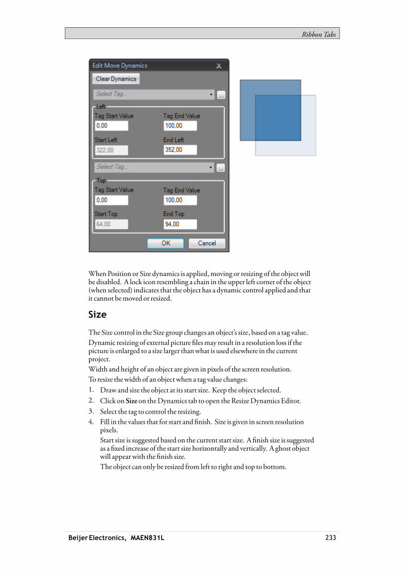
RibbonTabs
WhenPosition or Size dynamics is applied,moving or resizing of the object willbe disabled. A lock icon resembling a chain in the upper left corner of the object(when selected) indicates that the object has a dynamic control applied and thatit cannot bemoved or resized.
Size
The Size control in the Size group changes an object’s size, based on a tag value.Dynamic resizing of external picture filesmay result in a resolution loss if thepicture is enlarged to a size larger thanwhat is used elsewhere in the currentproject.Width and height of an object are given in pixels of the screen resolution.To resize thewidth of an object when a tag value changes:1. Draw and size the object at its start size. Keep the object selected.2. Click on Size on theDynamics tab to open theResizeDynamics Editor.3. Select the tag to control the resizing.4. Fill in the values that for start and finish. Size is given in screen resolution
pixels.Start size is suggested based on the current start size. A finish size is suggestedas a fixed increase of the start size horizontally and vertically. A ghost objectwill appearwith the finish size.The object can only be resized from left to right and top to bottom.
Beijer Electronics, MAEN831L 233
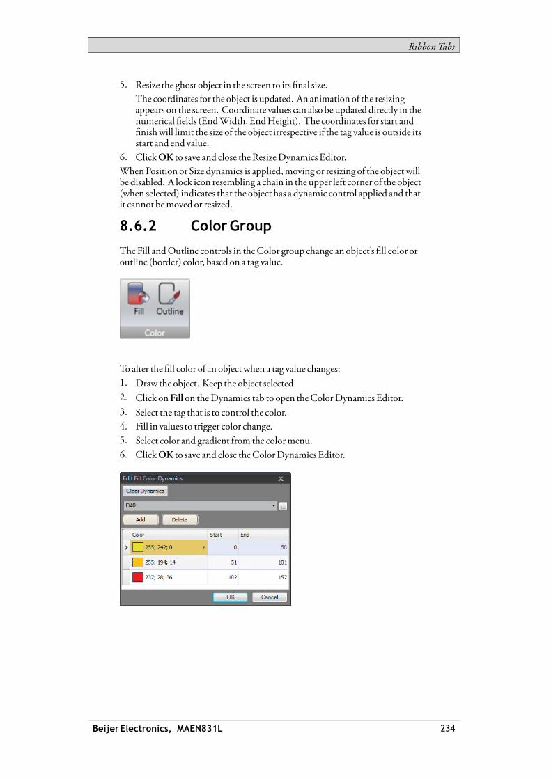
RibbonTabs
5. Resize the ghost object in the screen to its final size.The coordinates for the object is updated. An animation of the resizingappears on the screen. Coordinate values can also be updated directly in thenumerical fields (EndWidth, EndHeight). The coordinates for start andfinishwill limit the size of the object irrespective if the tag value is outside itsstart and end value.
6. ClickOK to save and close theResizeDynamics Editor.WhenPosition or Size dynamics is applied,moving or resizing of the object willbe disabled. A lock icon resembling a chain in the upper left corner of the object(when selected) indicates that the object has a dynamic control applied and thatit cannot bemoved or resized.
8.6.2 ColorGroup
TheFill andOutline controls in theColor group change an object’s fill color oroutline (border) color, based on a tag value.
To alter the fill color of an object when a tag value changes:1. Draw the object. Keep the object selected.2. Click onFill on theDynamics tab to open theColorDynamics Editor.3. Select the tag that is to control the color.4. Fill in values to trigger color change.5. Select color and gradient from the colormenu.6. ClickOK to save and close theColorDynamics Editor.
Beijer Electronics, MAEN831L 234

RibbonTabs
8.6.3 GeneralGroup
Visibility
TheVisible control in theVisibility groupdetermines if an object is to bedisplayed in the screen or not, based on a tag value.To hide an object when a tag value changes:1. Draw the object. Keep the object selected.2. Click onVisible on theDynamics tab.3. Select the tag that is to control visibility. The object will be visible on the
screen at a certain tag value.The selected valuewill be treated asTrue (visible). All other valueswill be treatedas False (invisible).
Blink
It is possible to select a tag to enable blinking depending on the tag’s current value.The selected valuewill be treated asTrue (blink enabled). All other valueswill betreated as False (blink disabled).The blink interval can be set dynamically or constantly.
Note:Security has higherpriority thandynamics.Visibility has higherpriority thanblink.
Beijer Electronics, MAEN831L 235

RibbonTabs
Related information
BlinkingObjects
General
The general control offers a possibility to alter the properties of objects iniXRuntime.
ConverterOperators
Converter operators are used to alter the properties of the objects. The converteroperators can be selected from theEdit general dynamicsdialog.
Parameter Description
BoolConverter Converts 0 to false andall other values totrue.
ColorConverter Converts value intervals to specifiedcolors.
LinearConverter Converts values according to the linearequation.
RawConverter Converts the value to anewvaluematching the target type.
TextLibraryGroupconverter Converts a value to a text.
EditGeneralDynamics
TheEdit general dynamicsdialog contains different properties depending onwhich object is selected. The dialog is accessed by clicking theGeneral controlon theGeneral group.
Parameter Converter Object Description
3DView ·bool Chart Set a 3D lookand feel for thechart
Acknowledgeall ·bool Alarmviewer Set visibility for theAcknowledgeAll button.
Beijer Electronics, MAEN831L 236
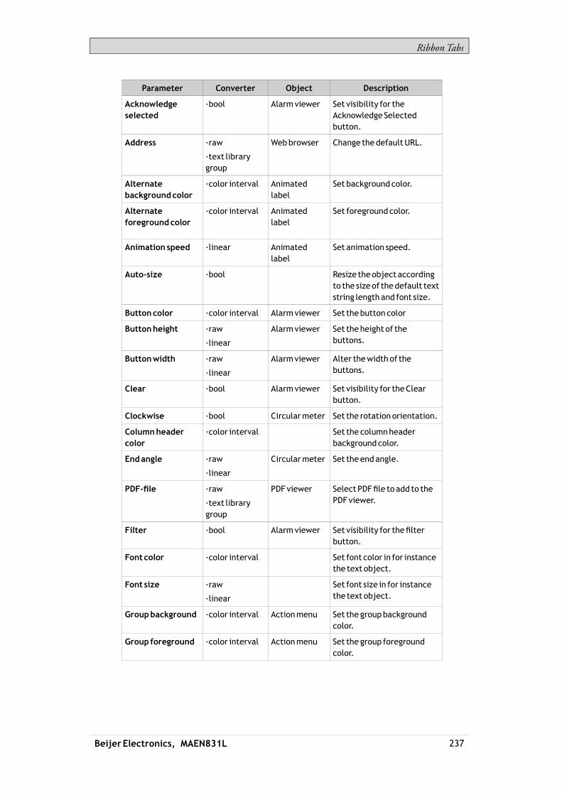
RibbonTabs
Parameter Converter Object Description
Acknowledgeselected
·bool Alarmviewer Set visibility for theAcknowledge Selectedbutton.
Address ·raw
·text librarygroup
Webbrowser Change thedefaultURL.
Alternatebackgroundcolor
·color interval Animatedlabel
Set backgroundcolor.
Alternateforegroundcolor
·color interval Animatedlabel
Set foregroundcolor.
Animation speed ·linear Animatedlabel
Set animation speed.
Auto-size ·bool Resize theobject accordingto the size of thedefault textstring lengthand font size.
Buttoncolor ·color interval Alarmviewer Set thebutton color
Buttonheight ·raw
·linear
Alarmviewer Set the height of thebuttons.
Buttonwidth ·raw
·linear
Alarmviewer Alter thewidthof thebuttons.
Clear ·bool Alarmviewer Set visibility for theClearbutton.
Clockwise ·bool Circularmeter Set the rotation orientation.
Columnheadercolor
·color interval Set the columnheaderbackgroundcolor.
Endangle ·raw
·linear
Circularmeter Set the endangle.
PDF-file ·raw
·text librarygroup
PDFviewer Select PDFfile to add to thePDFviewer.
Filter ·bool Alarmviewer Set visibility for thefilterbutton.
Font color ·color interval Set font color in for instancethe text object.
Font size ·raw
·linear
Set font size in for instancethe text object.
Groupbackground ·color interval Actionmenu Set the groupbackgroundcolor.
Group foreground ·color interval Actionmenu Set the group foregroundcolor.
Beijer Electronics, MAEN831L 237

RibbonTabs
Parameter Converter Object Description
Header ·raw
·text librarygroup
Chart Set the header.
HighRegionColor ·color interval Circularmeter Set the high region color.
HighRegionMax ·raw
·linear
Circularmeter Set themaximumvalue ofthe high region indicator.
HighRegionMin ·raw
·linear
Circularmeter Set theminimumvalueofthe high region indicator.
Indicator color ·color interval Set the indicator color in forinstance the circularmeterobject.
Info ·bool Alarmviewer Set visibility for the infobutton.
Active ·bool Chart Activateor stop thedatainput.
Enabled ·bool Enableor disable anobject.
Showheader ·bool Chart Set visibility for theheader.
Show legend ·bool Chart Set visibility for the legend.
Readonly ·bool Controlwhether for instanceananalognumeric objecteditable or not.
Auto-scaleX-axis ·bool Chart Usedwith the chartobject to togglewhetheriXRuntimeautomaticallyshould calculate theminimumandmaximumXAxis values or not.
ShowX-axis grid ·bool Chart Set visibility for theXAxisgrid.
ShowX-axis ·bool Chart Set visibility for theXAxis.
Auto-scaleY1-axis ·bool Chart Usedwith the chartobject to togglewhetheriXRuntimeautomaticallyshould calculate theminimumandmaximumY1Axis values or not.
ShowY1-axis grid ·bool Chart Set visibility for theY1Axisgrid.
ShowY1-axis ·bool Chart Set visibility for theY1Axis.
Beijer Electronics, MAEN831L 238

RibbonTabs
Parameter Converter Object Description
Auto-scaleY2-axis ·bool Chart Thebool converter canbeusedwith the chart object totogglewhether iXRuntimeautomatically shouldcalculate theminimumandmaximumY2Axis valuesor not.
ShowY2-axis grid ·bool Chart Set visibility for theY2Axisgrid.
ShowY2-axis ·bool Chart Set visibility for theY2Axis.
Lockaspect ratio ·bool Multi picture Usedwith themulti pictureobject to toggle theheight/width ratio of theobject.
Lowregioncolor ·color interval Circularmeter Set the low region color.
Lowregionmax ·raw
·linear
Circularmeter Set themaximumvalue ofthe low region indicator.
Lowregionmin ·raw
·linear
Circularmeter Set theminimumvalueofthe low region indicator.
Major ticks ·raw
·linear
Set the number of labeledtimemarks in for instancethe linearmeter object.
Maximum ·raw
·linear
Set the endvalueof thescale in for instance thelinearmeter object.
Majorvalue tics ·raw
·linear
Trendviewer Set the number of labeledscalemarks on the scale.
Maxvalue ·raw
·linear
Trendviewer Set the endvalueof thescale.
Minvalue ·raw
·linear
Trendviewer Set the start valueof thescale.
Minor value ticks ·raw
·linear
Trendviewer Set the number of scaleticks between twoadjacentmajor ticks on the scale.
Mediumregioncolor
·color interval Circularmeter Set themediumregion color.
Mediumregionmax
·raw
·linear
Circularmeter Set themaximumvalueof themediumregionindicator.
Mediumregionmin ·raw
·linear
Circularmeter Set theminimumvalueof themediumregionindicator.
Beijer Electronics, MAEN831L 239

RibbonTabs
Parameter Converter Object Description
Minimum ·raw
·linear
Set the start valueof thescale in for instance thelinearmeter object.
Minor ticks ·raw
·linear
Set the number of scaleticks between twoadjacentmajor ticks.
Lower limit ·raw
·linear
Analognumeric
Set theminimumvalue thatcanbeentered.
Opacity ·raw
·linear
Set the opacity of forinstance thePDF viewerobject.
Outline thickness ·raw
·linear
Set the outline thickness offor instance the rectangleobject.
Pictureheight ·raw
·linear
Button Set pictureheight.
Picturename ·raw
·text librarygroup
Picture Set thepicture shown in thepicture object.
Picture stretch ·bool Button Stretch apicture.
Picturewidth ·raw
·linear
Button Set thepicturewidth.
Play/Pause ·bool Alarmviewer Set visibility for thepausebutton.
Prefix ·raw
·text librarygroup
Analognumeric
Set aprefix to thedigitsentered.
RadiusX ·raw
·linear
Rectangle Set the radius of theXaxis inthe rectangle object.
RadiusY ·raw
·linear
Rectangle Set the radius of theYaxis.
Scale color ·color interval Circularmeter Set the scale color.
Scale ·bool Circularmeter Set visibility for the scale.
Selectedbackground
·color interval Actionmenu Set thebackgroundcolor ofthe selectedaction.
Selectedforeground
·color interval Actionmenu Set the foregroundcolor ofthe selectedaction.
Selected groupbackground
·color interval Actionmenu Set thebackgroundcolor ofthe selectedmenugroup.
Selected groupforeground
·color interval Actionmenu Set the foregroundcolor ofthe selectedmenugroup.
Separator color ·color interval Set the separator color.
Beijer Electronics, MAEN831L 240
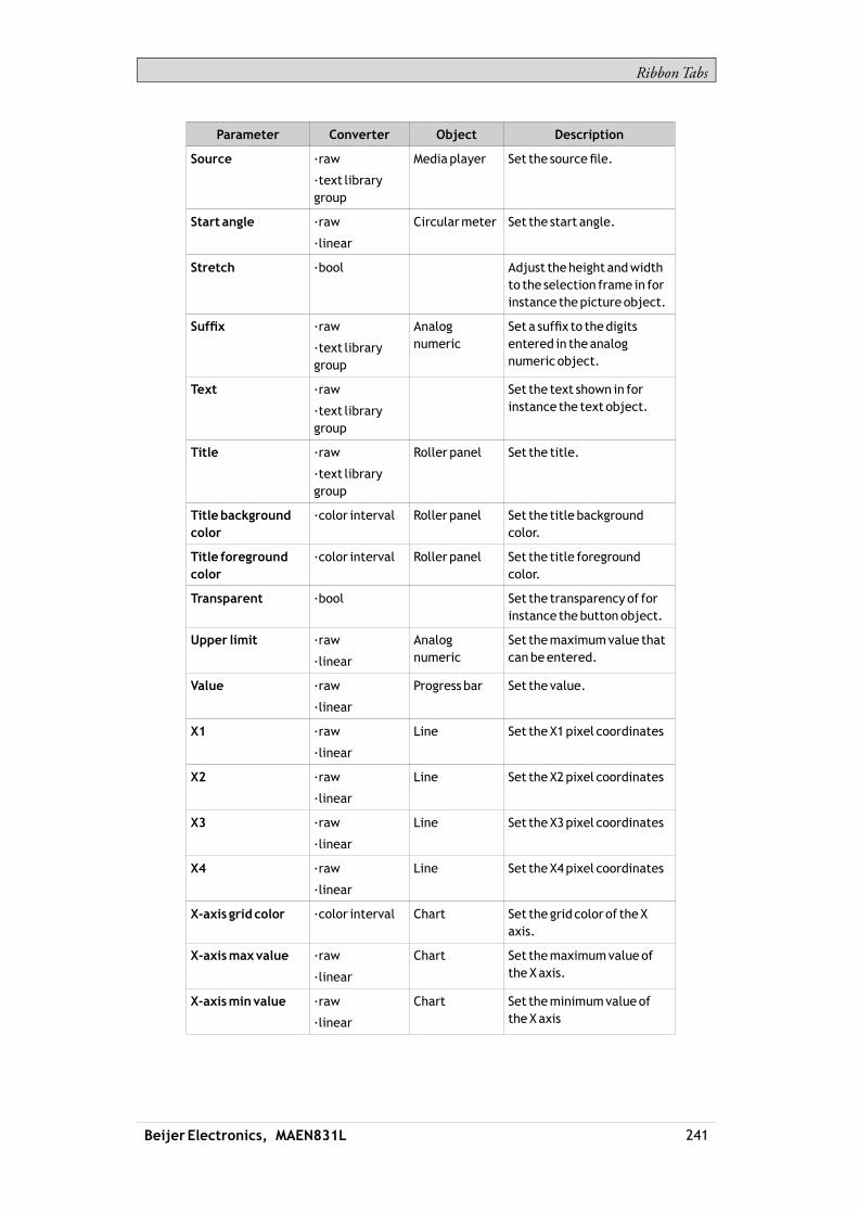
RibbonTabs
Parameter Converter Object Description
Source ·raw
·text librarygroup
Mediaplayer Set the sourcefile.
Start angle ·raw
·linear
Circularmeter Set the start angle.
Stretch ·bool Adjust theheight andwidthto the selection frame in forinstance thepictureobject.
Suffix ·raw
·text librarygroup
Analognumeric
Set a suffix to thedigitsentered in theanalognumeric object.
Text ·raw
·text librarygroup
Set the text shown in forinstance the text object.
Title ·raw
·text librarygroup
Roller panel Set the title.
Titlebackgroundcolor
·color interval Roller panel Set the title backgroundcolor.
Title foregroundcolor
·color interval Roller panel Set the title foregroundcolor.
Transparent ·bool Set the transparency of forinstance thebutton object.
Upper limit ·raw
·linear
Analognumeric
Set themaximumvalue thatcanbeentered.
Value ·raw
·linear
Progress bar Set the value.
X1 ·raw
·linear
Line Set theX1pixel coordinates
X2 ·raw
·linear
Line Set theX2pixel coordinates
X3 ·raw
·linear
Line Set theX3pixel coordinates
X4 ·raw
·linear
Line Set theX4pixel coordinates
X-axis grid color ·color interval Chart Set the grid color of theXaxis.
X-axismaxvalue ·raw
·linear
Chart Set themaximumvalue oftheXaxis.
X-axisminvalue ·raw
·linear
Chart Set theminimumvalueoftheXaxis
Beijer Electronics, MAEN831L 241

RibbonTabs
Parameter Converter Object Description
Y1-axis grid color ·color interval Chart Set the grid color of theY1axis.
Y1-axismaxvalue ·raw
·linear
Chart Set themaximumvalue oftheY1axis.
Y1-axisminvalue ·raw
·linear
Chart Set theminimumvalueoftheY1axis.
Y2-axis grid color ·color interval Chart Set the grid color of theY2axis.
Y2-axismaxvalue ·raw
·linear
Chart Set themaximumvalue oftheY2axis.
Y2-axisminvalue ·raw
·linear
Chart Set theminimumvalueoftheY2axis.
Related information
Text Library
8.7 GeneralRibbonTab
TheGeneral ribbon tab contains different property groups and controls fordifferent objects. Appearance can bemodified for graphical shapes and objects.Scale settings can bemade formeters and trend viewers. Additional settings can bemade for some objects.TheTag/Security group is available also on theHome ribbon tab.The general properties are described separately for each object.
Related information
HMIControls in theObjects group
MediaControls in theObjects group
Special Controls in theObjects group
WindowsControls in theObjects group
Tag/SecurityGroupon theHomeRibbonTab
8.8 ActionsRibbonTab
Actions can be triggered in variousways, for example by clicking a button. TheActions tab controls are used to define actions for objects. Alternatively, a scriptcan be used to trigger an action.An action is something that is performed, for example closing a screen. An actiontrigger is the act that generates an action, for example clicking a button.TheActions ribbon tab contains different control groups for different objects.
Beijer Electronics, MAEN831L 242
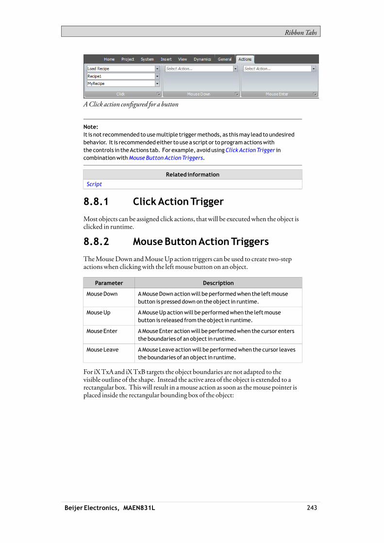
RibbonTabs
AClick action configured for a button
Note:It is not recommended tousemultiple triggermethods, as thismay lead toundesiredbehavior. It is recommendedeither to usea script or to programactionswiththe controls in theActions tab. For example, avoid usingClickActionTrigger incombinationwithMouseButtonActionTriggers.
Related information
Script
8.8.1 ClickActionTrigger
Most objects can be assigned click actions, thatwill be executedwhen the object isclicked in runtime.
8.8.2 MouseButtonActionTriggers
TheMouseDown andMouseUp action triggers can be used to create two-stepactionswhen clickingwith the leftmouse button on an object.
Parameter Description
MouseDown AMouseDownactionwill beperformedwhen the leftmousebutton is presseddownon theobject in runtime.
MouseUp AMouseUpactionwill beperformedwhen the leftmousebutton is released fromtheobject in runtime.
MouseEnter AMouseEnter actionwill beperformedwhen the cursor enterstheboundaries of anobject in runtime.
MouseLeave AMouseLeave actionwill beperformedwhen thecursor leavestheboundaries of anobject in runtime.
For iXTxA and iXTxB targets the object boundaries are not adapted to thevisible outline of the shape. Instead the active area of the object is extended to arectangular box. This will result in amouse action as soon as themouse pointer isplaced inside the rectangular bounding box of the object:
Beijer Electronics, MAEN831L 243

RibbonTabs
8.8.3 FunctionKeyActionTriggers
TheKeyDown andKeyUp action triggers can be used to create two-step actionsfor function keys.
Parameter Description
KeyDown AKeyDownactionwill beperformedwhena function key ispressed in runtime.
KeyUp AKeyUpactionwill beperformedwhena function key isreleased in runtime.
8.8.4 ValueChangedActionTriggers
Parameter Description
InputValueChanged
The InputValueChangedactionwill beperformedwhenavalueis enteredby theoperator.
ValueChanged TheValueChangedactionwill beperformedwhen the valueoftheobject has changed.
8.8.5 FocusActionTriggers
Parameter Description
GotFocus TheGot Focus actionwill be performedwhen theobject isselected.
Lost Focus TheLost Focus actionwill beperformedwhen theobject is nolonger selected.
8.8.6 NavigationActionTriggers
Parameter Description
Navigated TheNavigatedactionwill beperformedwhenhaving navigatedto the address entered in theaddressfield of theWebbrowserobject.
Navigating TheNavigating actionwill beperformedwhenhavingentered,but not reached, anaddress in theaddressfield of theWebbrowser object.
Beijer Electronics, MAEN831L 244
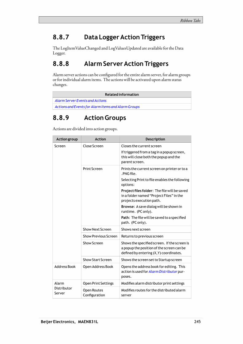
RibbonTabs
8.8.7 DataLoggerActionTriggers
TheLogItemValueChanged andLogValuesUpdated are available for theDataLogger.
8.8.8 AlarmServerActionTriggers
Alarm server actions can be configured for the entire alarm server, for alarm groupsor for individual alarm items. The actionswill be activated upon alarm statuschanges.
Related information
AlarmServer Events andActions
Actions andEvents forAlarm ItemsandAlarmGroups
8.8.9 ActionGroups
Actions are divided into action groups.
Actiongroup Action Description
Close Screen Closes the current screen
If triggered froma tag in apopup screen,thiswill closeboth thepopupand theparent screen.
Print Screen Prints the current screenonprinter or to a.PNGfile.
SelectingPrint tofile enables the followingoptions:
Projectfiles folder: Thefilewill be savedin a folder named“Project Files” in theprojects executionpath.
Browse: A savedialogwill be shown inruntime. (PConly).
Path: Thefilewill be saved to a specifiedpath. (PConly).
ShowNext Screen Showsnext screen
ShowPrevious Screen Returns toprevious screen
ShowScreen Shows the specified screen. If the screen isa popup thepositionof the screen canbedefinedbyentering (X,Y) coordinates.
Screen
ShowStart Screen Shows the screen set to Startup screen
Address Book OpenAddress Book Opens theaddress book for editing. Thisaction is used forAlarmDistributorpur-poses.
OpenPrint Settings Modifies alarmdistributorprint settingsAlarmDistributorServer
OpenRoutesConfiguration
Modifies routes for thedistributedalarmserver
Beijer Electronics, MAEN831L 245

RibbonTabs
Actiongroup Action Description
AcknowledgeAllAlarms
Acknowledges all alarms in all AlarmViewers
AcknowledgeSelectedAlarm
Acknowledges the selectedalarm in theAlarmViewer
Alarm Info Performs theaction configured for theAlarmevent info requested in theAlarmServer. Theaction is performedon theselectedAlarmViewer.
ClearAll Alarms Removeall alarms in all AlarmViewers
Filter Alarms Shows thefilter configuration dialog forthe selectedAlarmViewer
AlarmViewer(1)
PauseViewer Starts andpauses the selectedAlarmViewer
AuditTrail Export AuditTrailDatabase
Exports the audit trail database to aUSBstick (operatorpanel) or to a folder (PC).When this is done theaudit trail log iscleared.
Theexportwill be saved in a .SDFfile.
PanDown Pansdown in selectedchart
PanLeft Pans left in selected chart
PanRight Pans right in selected chart
PanUp Pansup in selectedchart
ResetView Resets anypanning and zoom in selectedchart
Zoom In Zooms into selected chart
Chart
ZoomOut Zoomsout of selected chart
BackupDatabase Performsabackupof theproject database
BackupDatabase forproject restore
Performsabackupof theproject databaseto thememory card. This action canbeusedwhenproject is copied tomemorycard, to update thedatabaseon thememory card. Whenaction is performed,theexisting databaseon thememory cardis replaced.
Only supported for iXTxAand iXTxBtargets.
Database
DatabaseExport Exports selecteddatabase in csv format
ClearDatalogger Clears the specifieddatalogger
LogOnce Makes the specifieddatalogger logonce
Start Logging Enables the specifieddatalogger
Datalogger
Stop Logging Disables the specifieddatalogger
Beijer Electronics, MAEN831L 246
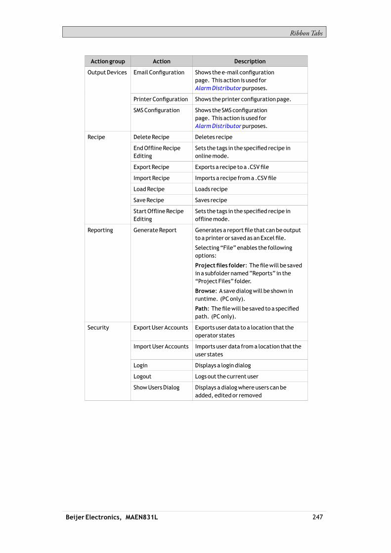
RibbonTabs
Actiongroup Action Description
Email Configuration Shows thee-mail configurationpage. This action is used forAlarmDistributorpurposes.
PrinterConfiguration Shows theprinter configurationpage.
OutputDevices
SMSConfiguration Shows the SMSconfigurationpage. This action is used forAlarmDistributorpurposes.
DeleteRecipe Deletes recipe
EndOfflineRecipeEditing
Sets the tags in the specified recipe inonlinemode.
Export Recipe Exports a recipe to a .CSVfile
Import Recipe Imports a recipe froma .CSVfile
LoadRecipe Loads recipe
SaveRecipe Saves recipe
Recipe
StartOfflineRecipeEditing
Sets the tags in the specified recipe inofflinemode.
Reporting GenerateReport Generates a reportfile that canbeoutputto aprinter or savedas anExcelfile.
Selecting“File” enables the followingoptions:
Projectfiles folder: Thefilewill be savedin a subfoldernamed”Reports” in the“Project Files” folder.
Browse: A savedialogwill be shown inruntime. (PConly).
Path: Thefilewill be saved to a specifiedpath. (PConly).
ExportUserAccounts Exports user data to a location that theoperator states
ImportUserAccounts Imports user data froma location that theuser states
Login Displays a logindialog
Logout Logs out the current user
Security
ShowUsersDialog Displays adialogwhereusers canbeadded, editedor removed
Beijer Electronics, MAEN831L 247

RibbonTabs
Actiongroup Action Description
ClearNon-VolatileValues
Clears all stored values for tagsmarkedasnon-volatile
DecrementAnalog(2) Decrements tag value
IncrementAnalog(2) Increments tag value
ResetTag(2) Resets tag to 0
SetAnalog(2) Sets tag to the specifiedvalue
Set String(2) Sets tag to the specified string
SetTag(2) Sets tag to 1
Tag
ToggleTag(2) Toggles tagbetween0 and1
ShowTrendViewerLegend
Displays the legend tool in the selectedtrend viewer,with apossibility to showandhide curves and todisplay values of aspecific trend viewer sample.
TrendViewer
TrendViewerHistory TheTrendViewerHistory action includesthe following choices (all applicable to theselected trend viewer):
On: Shows trendhistory fromwhentheactionwas triggered (includingoffset settingsmadeusing trend viewerdynamics).
Off: Returns to showing real time trendviewerdata.
Toggle: Allows entering and terminatinghistorymodeusing the sameobject (forexample abutton).
ShowDialog: Lets the user select a periodof time, forwhich to show trendviewerhistory.
ChangeActiveControllers
Defineswhich controllers are tobeactiveafter having restarted theproject
RunScript Executes a scriptmethod saved in a scriptmodule.
CloseApplication Closes the runtimeapplication.
CopyDebug Log toUSBMemory
Copies thedebug log to aUSBmemory.
DisableDebug Logger Disables thedebug logger.
EnableDebug Logger Enables thedebug logger.
Run Starts an external application
Scroll Left Scrolls the screencarousel object left
Scroll Right Scrolls the screencarousel object right
SetDateandTime Allows changingdateand time in theoperator panel
Other
Beijer Electronics, MAEN831L 248

RibbonTabs
Actiongroup Action Description
Set Language Sets the language in the operator panel tothe selected language
SetTimeZone,RegionandDaylightSaving
Allows changing timezone, regionanddaylight saving settings in theoperatorpanel
ShowBacklightSettings
Allows changingbacklight settings in theoperator panel
Whenapproaching 0%backlight, changesinbrightness levelmayno longer benoticeable in thepanel.
Completedimming (to 0%) is only possibleto achievewith themarinepanel types,such as iXT7AMand iXT15BM.
Show IP Settings Shows the IP settings in theoperator panel
(1)All AlarmViewer actionsmust beassociatedwith anAlarmViewer in the same screenas the objectwith theaction configured. This also applies to actions that affect allAlarms.(2)This action canbeusedwithAliases.
8.8.10 ScriptAction
Script actions are used to execute scriptmethods in scriptmodules, triggered byactions. Scriptmodules in the project can be selected, and for each scriptmoduleallmethods are listed alongwith their exposed parameters. Staticmethods arenot supported.
To apply a script to a selected object:1. Go to theActions group and select the appropriate action trigger.2. Select actionRunScriptunderOther.3. Select one of the scripts fromScriptModules.4. This results in a list of available scriptmethods for that specific scriptmodule.
Select scriptmethod.5. The parameters for the script appears in a dialogwith information about the
parameter name and type. Complete the settings by entering a tag or a fixedvalue for each parameter, and clickOK.
Beijer Electronics, MAEN831L 249

RibbonTabs
The script actionwill nowbe executedwhen the object is triggered.
Note:Script actionswill haveprecedenceover other script code for anobject.
Related information
Script
8.8.11 MultipleActions
Multiple actions can be configured by clicking small arrow in the lower rightcorner of any action group.
Note the small arrow in the lower right corner
The propertieswindow allows configuring and sorting additional actions. Theactions available dependofwhich object is selected in the screen prior to selectingtheActions ribbon tab.
Beijer Electronics, MAEN831L 250

RibbonTabs
After configuringmultiple actions, this is indicated for the action group on theActions tab.
Beijer Electronics, MAEN831L 251

TrendViewer
9 TrendViewer
This section describes the trend viewer object. TrendViewers are used to presentchronological data from controller tags. The curves in a trend viewer can havedifferent sources of data.The source of data can be a log item for a data logger. The values of the tagconnected to the log item is then stored in the projects database.The source can also be aTag. The trend viewer curve then only shows real-timevalues and is stored in aRAMcache.
Related information
Database
DatabaseExport
9.1 DefiningTrendViewerObjects
It is possible to define several independent trend viewer objects, in the same screenor in different screens. The number of trend viewer curves is limited only by theavailable amount ofmemory in the panel.
Note:A largenumber of trend viewerpens and short sampling intervalsmayaffectcommunicationperformance.
Related information
CommunicationPerformance
9.1.1 AddingaTrendViewerObject
A trend viewer object is added to a screen from theObjects group on theHomeribbon tab.Settings for the trend viewer object are available from theGeneral ribbon tabwhilethe trend viewer object is selected:
CurvesGroup
Trend viewer curves are defined using theEditCurves control.
Parameter Description
Add Adds anewcurve to the trend viewer object
Remove Removes the selected curve fromthe trend viewer object
Beijer Electronics, MAEN831L 252

TrendViewer
Parameter Description
Name The symbolic nameof the curve. This name is shown if aTrendViewer Legend is used.
Tag The tag topresent values for
Log Item The itemtobe logged
Expression Expression onacurve is evaluatedandappliedwhen thecurve is drawn. If theexpression valuewhen the tag isloggedor cached is of interest, theexpressionon the logitemor the tag canbeused. See sectionExpressions
Color Thecolor of the curve
Thickness Line thickness
MinimumValueTag A tag that dynamically setswhat valueon thecurve thatcorresponds to theminimumvalueof theYaxis. Thispropertywill scale the curvewhen the valueof the tag isdifferent fromtheminimumvalueof theYaxis (optional).
MaximumValueTag The tag that dynamically setswhat value on thecurvethat corresponds to themaximumvalueof theYaxis. Thispropertywill scale the curvewhen the valueof the tag isdifferent fromthemaximumvalueof theYaxis (optional)
DynamicsGroup
Several trend viewer properties can bemade dynamic, i. e. dependent on tagvalues. Thismay be useful, for example, whenwanting to present trend viewervalues of different formats in the same trend viewer object.If dynamic trend viewer properties are used, the corresponding property settingsmade in theValue Scale group for the trend viewer object are ignored.
Parameter Description
Value ScaleMin/ValueScaleMax
Minimum/maximumvalue of theY-scale. Thedesignmodevalue is usedonly for increasedunderstanding indesign timewhen tag values donotaffect theminimumandmaximumvalues.
TimeSpan The time spanof theX-axis in seconds.
TimeOffset inHistoryMode
Makes it possible to useanoffset to stepback in historymode. The start value iswhenhistorymodewasentered.Theunit is seconds.
If theTimeSpan value is increased, the trend viewerwill initially display only theprevious number of entries (thatwas displayed before the increased time span).It will not collect older data for display. Onlywhen the additional time addedonto the time span has elapsed, the cachewill be filledwith data and a full curveis displayed.
Beijer Electronics, MAEN831L 253
TrendViewer
ValueScaleGroup
The value scale group controls the vertical scale (y-axis). If dynamic trend viewerproperties are used, the settingsmade for these properties in the value scale groupwill be ignored.
Parameter Description
MinValue/MaxValue Start/end valueof scale
Major Ticks Numberof labeled scalemarks on the scale
Minor Ticks Numberof scale ticks between twoadjacentmajor ticks
TimeScaleGroup
Parameter Description
TimeRange Visible time span for a trend viewer inHour:Minute:Secondformat. Allowedvalues range from00:00:00 to 23:59:59.
Major Ticks Numberof labeled timemarks. This propertywill beignored inHistoricalMode inTrendViewer.
StyleGroup
Parameter Description
Style Predefinedgraphical styles for the trend viewer
VisibilityGroup
Parameter Description
Scale Whenunchecked, the scale color of the trend ismadetransparent. Scale color is set fromOtherColors in theFormat groupon theHome ribbon tab.
Grid Whenunchecked, thegrid color of the trend viewer ismade transparent. Grid color is set fromOtherColors inthe Format groupon theHome ribbon tab.
9.1.2 TrendViewerLegend
In runtime, it is possible to display a trend viewer legend tool using the ShowTrendViewer Legend action. The trend viewer legend tool is a floatingwindowthat displays the name and color of the curves in the current trend viewer object.Curves can bemade invisible by clicking the visibility icon.Use the needle directly in the trend viewer to select a specific occasion. The valuesof all curves at the current position are displayed in the trend viewer legend tool.
Beijer Electronics, MAEN831L 254

TrendViewer
9.2 HistoricalMode inTrendViewer
Tobe able to showhistorical data in a trend viewer, the curves needs to beconnected to log items from a data logger.To show trend viewer history, it is necessary to define trend actions to show andclose the historical trend viewer. These actions can for example be programmed asbutton click actions. It is also possible to let the user select a time period.Major ticks settings for time axis will be ignored in historical trend viewers. Inhistorical trend viewers the date and timewill be viewed at start and end time. Thetext “history” is visible in themiddle of the time axis.
Related information
Performance in the operator panel
Database
ClickActionTrigger
Beijer Electronics, MAEN831L 255

Data Logger
10 DataLogger
Data can be logged and saved in the iXDeveloper database.Anynumber of tags can be connected to a data logger, and data values irrespectiveof type can be logged. A project can havemultiple data loggers with differentsampling alternatives.When installing iXDeveloper, aDatabaseViewer is automatically installed andavailable fromWindows Startmenu. TheDatabaseViewermakes it possible toopen the database file and inspect logged data, and to export the file to Excel.Logged data can also be viewed in the trend viewer object by selecting a LogItemfor a curve in the EditCurves dialog.If iXRuntime is restarted at somepoint during the data logging, an additionalempty row is added in theData Logger table in order to clearly visualize theinterruption in theTrendViewer.
Note:Logging of data consumes systemresources andmemory. To savememory, it ispreferable that all LogItems that shouldbe loggedwith the same sampling intervals areplaced in the samedata logger.
Note:In order to import or export .xls-filesMicrosoft Excelmust be installed.
Any individual data logger database can be exported in csv format using theDatabase Export action. It is recommended to use the database exportmethodrather than the backupmethod.
Related information
Database
DatabaseExport
Adding aTrendViewerObject
10.1 DataLogging Strategies
Logging of data can bemade at time intervals or based on changed tag values.Logging of data can bemade either by collecting all samples at every log event, orby collecting only changed values. Collecting only changed values savesmemoryand improves performance.
10.1.1 LoggingBasedonTime Interval
To collect data that changes frequently, logging data based on time interval isrecommended.
Beijer Electronics, MAEN831L 256

Data Logger
10.1.2 LoggingBasedonChangedTagValue
To control sampling of data by othermeans than regular time interval, you haveto set up a separate tag to be used as a trigger. When the value of the trigger tagchanges the log item is logged.
10.1.3 Maximizing theLifetimeof theStorageMedia
The storagemedia in the iXpanel is based onFlash SSD (Solid StateDrive).Flash SSDhas nomoving ormechanical parts, which gives high and reliableperformance. The Flash SSDcan handle data very fast and efficiently and thedata is controlled by the drivemanufacturers’ confidential algorithm. As thealgorithm is intellectual property it is not possible to calculate the lifetime, thedrivemanufacturers only publish the numbers of reads andwrites.Best practise is tominimize number ofwrites tomaximize the lifetime of the FlashSSD. Follow the advice below to reduce the risk of prematurewear out (before theestimated lifetime). Anonworking Flash SSD stops the panel fromoperating.• Donot log valueswith higher accuracy than needed. For example, avoid
logging of floating point values.• Reduce high fluctuating values by using the hysteresis functionality in the
connected controller.• Collect valueswith high fluctuating values in the same logger and do notmix
with stable values. Collect slow changing values in other loggers.• Donot logwith higher refresh rate thanneeded.• Disable logging completelywhen information is not needed, for example
when themachine is not running.• Use default settingLog changes only in the property setting of the logger.• Keep the log size to aminimum, as few rows as needed.• Avoid extensive filewritingwhen controlling storage via script.
10.2 AddingaDataLogger
Adata logger can be added to the project from the Insert ribbon tab. The datalogger configuration pages are used to set upwhich values to log.
Beijer Electronics, MAEN831L 257
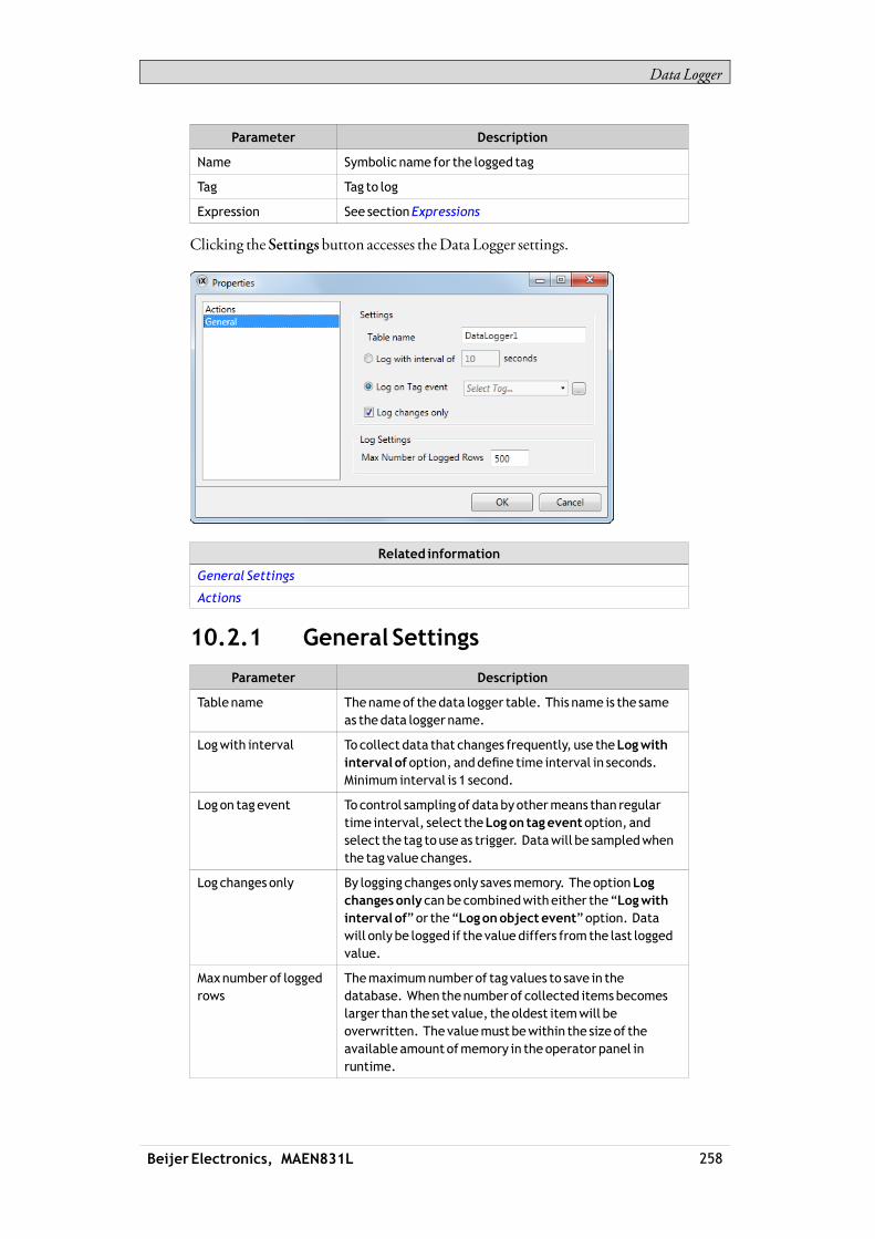
Data Logger
Parameter Description
Name Symbolic name for the logged tag
Tag Tag to log
Expression See sectionExpressions
Clicking the Settings button accesses theData Logger settings.
Related information
General Settings
Actions
10.2.1 General Settings
Parameter Description
Tablename Thenameof thedata logger table. This name is the sameas thedata logger name.
Logwith interval To collect data that changes frequently, use theLogwithinterval ofoption, anddefine time interval in seconds.Minimum interval is 1 second.
Logon tagevent To control sampling of databyothermeans than regulartime interval, select theLogon tageventoption, andselect the tag touse as trigger. Datawill be sampledwhenthe tag value changes.
Log changes only By logging changes only savesmemory. TheoptionLogchangesonly canbe combinedwitheither the“Logwithinterval of”or the“Logonobjectevent”option. Datawill only be logged if the valuediffers from the last loggedvalue.
Maxnumber of loggedrows
Themaximumnumberof tag values to save in thedatabase. When thenumberof collected itemsbecomeslarger than the set value, theoldest itemwill beoverwritten. Thevaluemust bewithin the sizeof theavailable amountofmemory in theoperator panel inruntime.
Beijer Electronics, MAEN831L 258
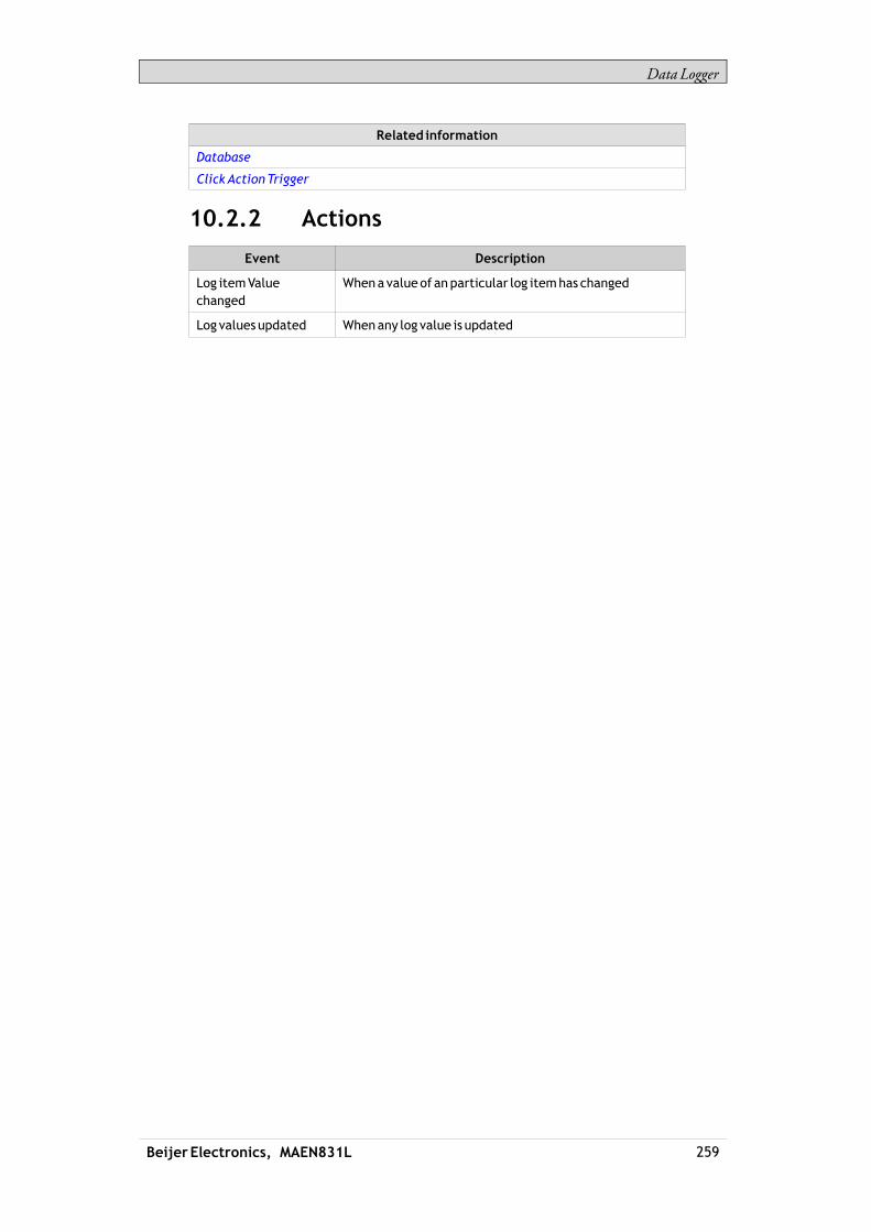
Data Logger
Related information
Database
ClickActionTrigger
10.2.2 Actions
Event Description
Log itemValuechanged
Whenavalueof anparticular log itemhas changed
Log values updated Whenany log value is updated
Beijer Electronics, MAEN831L 259
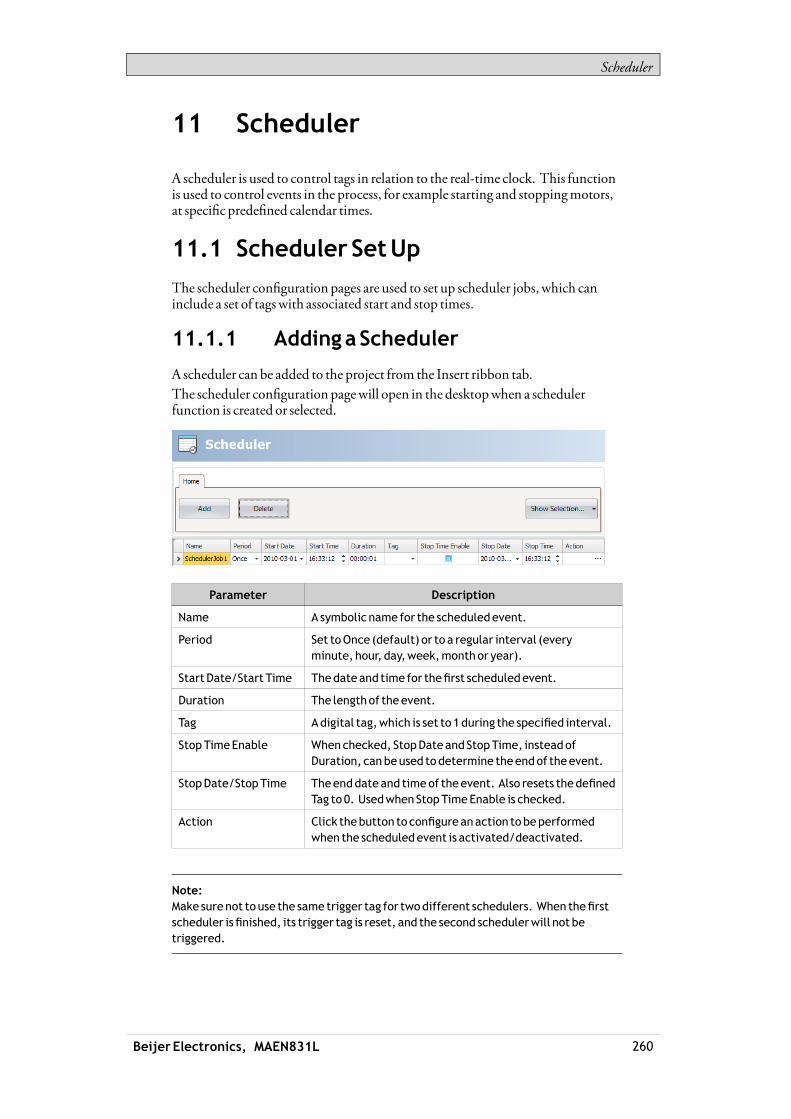
Scheduler
11 Scheduler
A scheduler is used to control tags in relation to the real-time clock. This functionis used to control events in the process, for example starting and stoppingmotors,at specific predefined calendar times.
11.1 Scheduler SetUp
The scheduler configuration pages are used to set up scheduler jobs, which caninclude a set of tagswith associated start and stop times.
11.1.1 AddingaScheduler
A scheduler can be added to the project from the Insert ribbon tab.The scheduler configuration pagewill open in the desktopwhen a schedulerfunction is created or selected.
Parameter Description
Name A symbolic name for the scheduledevent.
Period Set toOnce (default) or to a regular interval (everyminute, hour, day,week,monthor year).
Start Date/Start Time Thedateand time for thefirst scheduledevent.
Duration The lengthof the event.
Tag Adigital tag,which is set to 1during the specified interval.
StopTimeEnable Whenchecked, StopDateand StopTime, insteadofDuration, canbeused todetermine theendof theevent.
StopDate/StopTime Theenddateand timeof theevent. Also resets thedefinedTag to 0. UsedwhenStopTimeEnable is checked.
Action Click thebutton to configureanaction tobeperformedwhen the scheduledevent is activated/deactivated.
Note:Make surenot to use the same trigger tag for twodifferent schedulers. When thefirstscheduler isfinished, its trigger tag is reset, and the second schedulerwill not betriggered.
Beijer Electronics, MAEN831L 260

Reports
12 Reports
The report generator allows generatingExcel reports based on anMicrosoft Excelmade report template.The generated report can be output to a printer or saved as anExcel file.
12.1 ReportsTemplateSetup
The tag data to be displayed in the report file are set up in the template file using“placeholders”.The placeholders acts as substitute for the actual tag data that is to be insertedwhen the report is generated in iXRuntime.To add a placeholder, enter the following text inside a cell in the Excel reporttemplate:<#Tag(TagName)>Replace “TagName”with the actual name of the tag to be displayed.When the template file is complete it needs to be added to the iXDeveloperproject.
Note:The tagplaceholders canonlybeused in the cells of theExcel templatefile, they cannot beused in, for example,Microsoft ExcelWordArt texts.
12.1.1 Limitations
• Microsoft Excel xlsx format is not supported by the report generator.• Microsoft Excel xls format only supports 65536 rows. Ifmore data is stored in
the report, informationmay be lost.• Reports containing charts and pictures can not be printed from apanel target.• The report generation is not an instant process. Itmay elapse a shorter period
of time between the first sampled tag and the last sampled tag, depending onthe number of tags to process.
12.1.2 DatabaseDrivenReports
Tobe able to create database driven reports, the report templatemust be preparedas described in these instructions:
ConfigurationSheet
The configuration sheet is a repositorywhere configurations on theMicrosoftExcel report template can bemade. This sheetwill not be visible in the generatedreport.1. Create a newworksheet in the report template. Name the sheet <#Config>.
Beijer Electronics, MAEN831L 261

Reports
2. Row10, and all rows below, in columnA andB canbe used to configure theSQLqueries. Enter the SQLquery in columnB.Use the corresponding cell incolumnA to enter a name for the query. The namewill be used to refer to thequery in the report template.
Enter the SQLqueries in the following format:SQL(DatabaseName; SQLquery)Example: SQL(General; SELECT*FROMDataLogger1)There are two available databases: General andAuditTrail.
Present theDatabaseData in theReport
The data retrieved from the SQLdatabase, using the queries in the configurationsheet, can be presented in the report using “named ranges” inMicrosoft Excel.A named range is created inMicrosoft Excel by following these steps:1. Select the cells to be included in a named range.2. Click theDefinename command from the Insertmenu. (InExcel 2007, go
to theFormulas tab and chooseNameManager).3. Enter a name for the range. The namemust be entered in the following
format:“__QueryName__”.Replace “QueryName”with the name that you have chosen for your SQLquery.
To present the data in the report, enter the following syntax into the cells includedin the named range:<#QueryName.DatabaseColumnName>Replace the “DatabaseColumnName” entrywith the actual name of the table inthe SQLdatabase that youwish to present in the report.
Note:It is possible to use thenamed range cells inMicrosoft Excel charts and functions.Tobeable touse thenamed range in functions, anempty rowmust be insertedunderthenamed rangecells. This empty rowmust also be included in the function.
Related information
Adding aReport
12.2 Reports SetUp
The reports configuration page are available from the Insert ribbon tab.
Related information
InsertRibbonTab
Beijer Electronics, MAEN831L 262

Reports
12.3 AddingaReport
Add aMicrosoft Excel report template by pressingAdd in the reportsconfiguration page. In the appearingAdd report dialog, type in or browse to thelocation of the Excel template file.If any changes aremade to a report template after it has been uploaded to theproject, the template has to be uploaded again.The template files being added to the projectmust have unique file names.
Parameter Description
Name A symbolic name for the report.
File name Thenameof theMicrosoft Excel report template.
TheShowSelection/ShowAll button can be used to set up a filter of displayeditems.
Related information
Performance in the operator panel
Filtering Items
ConfigurationPages
ActionGroups
OutputDevicesGroup
Beijer Electronics, MAEN831L 263

RecipeManagement
13 RecipeManagement
Recipesmake it possible for a set of tags to be saved in the operator panel tobe downloaded at later time. The operator can download a saved recipe tothe controller, whichwill start workingwith the new values. Recipe librariesconsisting of recipeswith different sets of parameters can be created, allowingreuse of large sets of parameters.Recipes can be created during the design of the project or from the operator panel.Recipe data is stored in the operator panel database. Recipe handling functionssuch as loading, storing, copying and deleting recipes are handledwith actions.
Related information
Database
ActionsRibbonTab
13.1 RecipeSetup
Recipes consist of a set of recipe tags and of recipe data (values).
13.1.1 AddingaRecipeManager
The recipe function is added to the project from the Insert ribbon tab. Therecipe configuration pages are used tomanage tag sets and values via theTagConfiguration tab and theRuntimeData tab.
TagConfigurationTab
First add tags to be used by the recipe function from the tags configuration page.Then define a set of recipe items on theTagConfiguration tab of theRecipefunction, and connect them to the tags you defined. The data type is already set inthe configuration of the tags.
Beijer Electronics, MAEN831L 264

RecipeManagement
RuntimeDataTab
The actual recipes are created under theRuntimeData tab. Give the recipe a title,and type a value for each recipe item. A recipe can include amaximumof 256items.The recipe namehas to be an alphanumeric string, beginningwith a letter.Name strings can contain letters (a-z, A-Z), numbers (0-9), and underscore (‘_’)characters. Some systemdevice names such asCOM1andAUXare invalid.
Related information
InvalidNames
Beijer Electronics, MAEN831L 265

RecipeManagement
13.2 Recipes in the iXpanel
Some recipe actions can be performed by the operator in runtime.
13.2.1 LoadingRecipes
Recipes can be transferred to the controller using aLoad recipe actionwhen theoperator panel is running. Thismeans that the recipe values are transferred to thecontroller. A list of available recipes is displayedwhen theLoad recipe action isactivated. Select a recipe in the list and press [Enter] tomake the controller runwith the downloaded values.
13.2.2 SavingRecipes
TheSave recipe action can be usedwhen the operator panel is running. Tagsdefined on theTagConfiguration tab are included in the recipe. Correspondingtag values are stored in the selected recipe filewhen Save recipe is performed. It ispossible to define an explicit recipe, thatwill be overwritten if it already exists whenperforming the SaveRecipe action.
13.2.3 CreatingRecipes in the iXpanel
The Save recipe action is also used to create recipes in runtime. Instead of definingan explicit recipe to overwrite, the recipe data field is left open. In this case, theoperatorwill be prompted to save the recipewith anyname, or to overwrite anexisting recipe.
13.2.4 EditingRecipesOffline
It is possible to edit existing recipes in the panel without transferring values to thecontroller, by setting the recipe tags in offlinemode. Recipe tags in offlinemodewill not receive any data from the controller, and no valueswill bewritten to thecontroller.In offlinemode, the Load recipe and Save recipe actionswill not affect values inthe controller.Internal tagsmay be used for recipes, butwill not be affected by offlinemode.Actions are used to start and endofflinemode:
Beijer Electronics, MAEN831L 266

RecipeManagement
Action Description
Start offline recipeediting
Sets the tags in the specified recipe in offlinemode. Anotificationmessage is shown.
Endoffline recipeediting
Sets the tags in the specified recipe in onlinemode, andthe tags areupdated fromthe controller.
Anotificationmessage is displayed during offlinemode.
Example
1. ClickRecipe on the Insert ribbon tab.TheRecipe configuration page opens in the desktop area.
2. Add recipe tags on theTagConfiguration tab of theRecipe configurationpage and connect them to controller tags.
3. Add a recipe on theRuntimeData tab.4. Create a screenwith four buttons.5. Connect two of the buttons to theLoadRecipe and SaveRecipe actions.
Select the recipe title from theRuntimeData tab forRecipeData.6. Connect the other two buttons to the Start offline recipe editing andEnd
offline recipe editing actions.7. Run the project and test the functionality:
a. Click Start offline recipe editing.The tags are set in offlinemode.
b. Click Start offline recipe editing.The tags are filledwith data from the recipe.
c. Change the data.d. Click Save recipe.
The data in the tags is written to the recipe.e. ClickEndoffline recipe editing.
The tags are set in onlinemode and the values are updatedwith data fromthe controller.
13.3 RecipeExport
A recipe can be exported as a .csv file and saved to aUSB stick, an externalmemorycard or to the project files folder. The export is configured through the “ExportRecipe” action available from theRecipe action group.
Note:Recipeexport is not supportedduring project simulation.
Beijer Electronics, MAEN831L 267

RecipeManagement
13.3.1 RecipeExport fromanoperatorpanelTarget
It is possible to selectExport to the Project Files Folder,Export toUSB, orExportto externalmemory card, and also to set another name of the export file.It is also possible to select the requested delimiter in the .csv file (commaorsemicolon).
Beijer Electronics, MAEN831L 268

RecipeManagement
13.3.2 RecipeExport fromaPCTarget
It is possible to selectBrowse and Select an export path,Export to Path or theExport toProject Files folder, and also setting another name of the export file.TheBrowse andSelect an export path option allows browsing for desired exportdestination in runtime. Thismay be useful if available folders in runtime areunknownwhendesigning the project.Select theExport toPath optionwhen youwant to set the pathwhen designing theproject. If the pre-defined path is not valid in runtime, the operatormay browsethe PC environment by clicking a browse button.It is also possible to select the requested delimiter in the .csv file (commaorsemicolon).
13.4 Recipe Import
A recipe that previously has been exported as a .csv file, can be imported back intorecipe database. The import is configured through the “ImportRecipe” actionavailable from theRecipeAction group.
Beijer Electronics, MAEN831L 269

RecipeManagement
Note:Recipe import is not supportedduring project simulation.
13.4.1 Recipe Import to an iXpanelTarget
It is possible to import the csv file using the Import fromUSB, Import fromexternalmemory card or the Import fromProject Files folder selections and alsosetting the name of the import file.It is also possible to select the requested delimiter in the .csv file (commaorsemicolon).It can be selectedwhether to ignore the newdata or replace the old data, if therecipe data already exists.
Beijer Electronics, MAEN831L 270

RecipeManagement
13.4.2 Recipe Import to aPCTarget
It is possible to selectBrowse and Select a path for import file, Import frompathor Import fromProject Files folder, and also setting the name of the import file.TheBrowse andSelect a path for import file option allows browsing for desiredimport destination in runtime. Thismay be useful if available folders in runtimeare unknownwhen designing the project.Select the Import frompath optionwhen youwant to set the pathwhen designingthe project.It is also possible to select the requested delimiter in the .csv file (commaorsemicolon).It can be selectedwhether to ignore the newdata or replace the old data, if therecipes already exists.
Beijer Electronics, MAEN831L 271

FunctionKeys
14 FunctionKeys
Function keys can be configured to run actions or to run scripts.
14.1 Definitions
A standardPCkeyboard has 12 function keys, F1 - F12.A function key can be configured to affect only a particular screen or to be global.Global function keys behave identically for all screens. A global definition canalways be accessedwhen the operator panel is running, provided that the currentscreen does not have a screen definition for that function key. Screen functionkeys have higher priority than global function keys. Function keys included inbackground screens have lower priority than screen function keys, but higherpriority than global function keys.For touch panel andPC targets, the Function keys function is added via theInsert ribbon tab, and allows configuration of up to 24 function keys (even if theconnected keyboard does not supportmore than 12 function keys).
Related information
SecurityManagement
14.2 ConfiguringFunctionKeys
Function keys can be configured to run actions or to run scripts.
14.2.1 FunctionKeyActions
Todefine function key actions:1. Click onFunctionKeys in the Project Explorer to open the function keys
configuration page.2. SelectGlobal orScreen.3. Select the function key to be defined.
Beijer Electronics, MAEN831L 272

FunctionKeys
4. Click on the buttonnext to the action to display the actions editor. Define theaction to be performedwhen the function key is pressed or released.
5. In the column Security groups required it is possible to specify security groupaccessibility for the function key.
Multiple actions can be configured for a function key.It is only possible to activate two tags connected to function keys at the same time.Thismeans that ifmore than two function keys are pressed at the same time, onlythe first twowill be activated.Should further function key actions be needed in addition to those available forthe panel in question, this could be solved by adding buttons or other objects onscreen, connecting these to the desired actions.
Note:The function keyswill bedisabled if thebacklight of thepanel is disabled.
Related information
FunctionKeyActionTriggers
MultipleActions
Beijer Electronics, MAEN831L 273
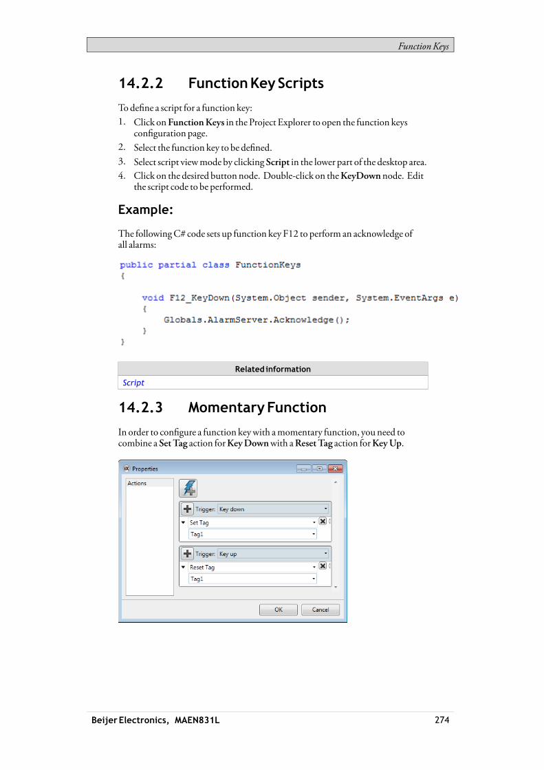
FunctionKeys
14.2.2 FunctionKeyScripts
Todefine a script for a function key:1. Click onFunctionKeys in the Project Explorer to open the function keys
configuration page.2. Select the function key to be defined.3. Select script viewmode by clicking Script in the lower part of the desktop area.4. Click on the desired buttonnode. Double-click on theKeyDownnode. Edit
the script code to be performed.
Example:
The followingC# code sets up function key F12 to perform an acknowledge ofall alarms:
Related information
Script
14.2.3 MomentaryFunction
In order to configure a function keywith amomentary function, youneed tocombine a SetTag action forKeyDownwith aResetTag action forKeyUp.
Beijer Electronics, MAEN831L 274

FunctionKeys
Changeof ScreenDuringMomentaryExecution
There are a few special cases to be aware ofwhen, during execution of themomentary function, another screen is opened that contains settings for thefunction key in use.Then, dependent on theFunctionKeyContext settings,Global orScreen (local),therewill be different outcomes:• Case 1: A local function key is pressed.
A change to another screen occurs.Result: The up action for the local key is executed. Nonewdownor upactions are executed on the second screen as long as the key is pressed.
• Case 2: Aglobal function key is pressed.A change to another screen occurs, inwhich there is no local setting for thesame key.Result: Nothing happens at screen change. The up action for the global keyis executedwhen the key is released.
• Case 3: Aglobal function key is pressed.A change to another screen occurs, inwhich there is a local setting for the samekey.Result: The up action for the global key is executed. Nonewdownor upactions are executed on the second screen as long as the key is pressed.
Note:AScreen (local) function key commandhaspriority over aGlobal function keycommand.
Beijer Electronics, MAEN831L 275

AlarmManagement
15 AlarmManagement
An alarm is used to call attention to an event that requires immediate action. Analarm is set when a certain condition ismet. An alarm condition is designed as alogical evaluation of a tag value. Alarms can be divided into groups to create anorder of priority.Alarmnotification can bemade in the followingways:
Alarm Indicator
AlarmViewer
Distribution via SMS, e-mail or printer via theAlarmDistributor
The alarm server database can be exported in csv format using theDatabaseExport action.
Related information
DatabaseExport
15.1 AlarmConditions
Alarms can assume the following conditions:
Alarmcondition Description
Active Thealarmcondition ismet, and thealarm is notacknowledged
Inactive Thealarmhas returned tonormal condition, but has notbeenacknowledged
Acknowledged Thealarmcondition is stillmet, but the alarm isacknowledged
Normal Thealarmhas returned tonormal conditionandhasbeenacknowledged
15.2 AlarmServer
The alarm server function is predefined in the Project Explorer. Clicking on itopens the alarm server configuration pages in the desktop.General alarm server properties are available by clicking the Settings button.
Beijer Electronics, MAEN831L 276
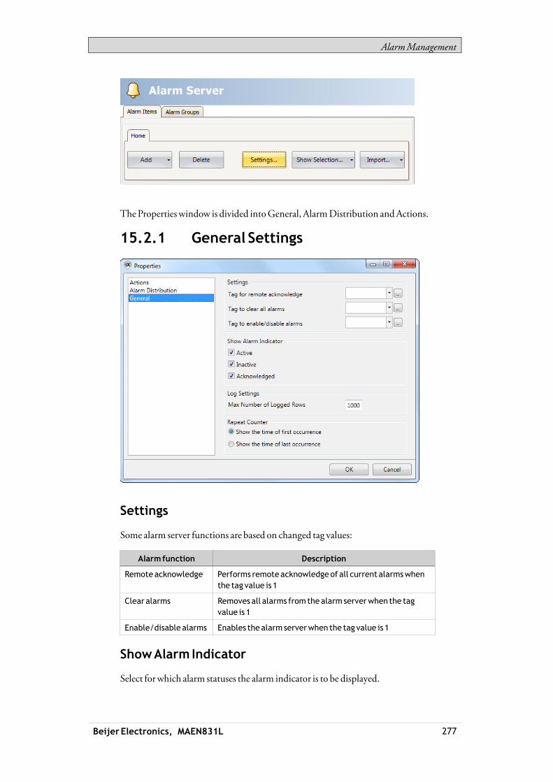
AlarmManagement
TheProperties window is divided intoGeneral, AlarmDistribution andActions.
15.2.1 General Settings
Settings
Some alarm server functions are based on changed tag values:
Alarmfunction Description
Remoteacknowledge Performs remoteacknowledgeof all current alarmswhenthe tag value is 1
Clear alarms Removes all alarms fromthealarm serverwhen the tagvalue is 1
Enable/disable alarms Enables the alarm serverwhen the tag value is 1
ShowAlarm Indicator
Select forwhich alarm statuses the alarm indicator is to be displayed.
Beijer Electronics, MAEN831L 277
AlarmManagement
LogSettings
Parameter Description
MaxNumberof LoggedRows
Themaximumnumberof alarms to save in thedatabase. Ifthe number of collected itemsbecomes larger than the setvalue, theoldest itemwill bedeleted. The valuemust bewithin the sizeof the available amount ofmemory in theoperator panel in runtime.
RepeatCounter
To avoid that an alarm that is triggered repeatedly results inmultiple entries in thealarm list,RepeatCount can be used. The current alarmwill then only appearonce in the alarm list, and number of times the alarm is triggeredwill be includedin the alarm text. For display in theAlarmViewer and for logging, select whetherto show the time of the first or last occurrence of the alarm.
15.2.2 AlarmServerEvents andActions
Actions can be configured for the entire alarm server. One ormultiple actions canbe configuredwhen a particular alarm server event occurs.SelectActions in theAlarmServer properties page to configure actions for thealarm server.Actions for the following alarm server events can be configured:
AlarmAcknowledge
The specified actions are triggered once for every alarm that is acknowledged.
AlarmActive
The specified actions are triggered once for every alarm that becomes active.
AlarmDeleted
The specified actions are triggered oncewhen theClear button in theAlarmViewer is pressed, if at least one alarm is deleted.
AlarmEvent InfoRequested
The specified actions for the selected alarm are triggeredwhen the Infobutton intheAlarmViewer is pressed.The actions are applied for the individual alarmfirst. If no action is specified forthe alarm, the actions are applied for the group. If no action is specified for thegroup, the actions are applied for the alarm server.
Alarm Inactive
The specified actions are triggered once for each alarm, forwhich the alarmcondition is no longermet.
Beijer Electronics, MAEN831L 278

AlarmManagement
AlarmNormal
The specified actions are triggered once for each acknowledged alarm, forwhichthe alarm condition is no longermet.
AlarmsChanged
This event is intended primarily for scripting, in order to avoid performanceloss thatmay occurwhenmany alarms change status at once. AlarmsChangedincludes status changes based onAlarmAcknowledge, AlarmActive, AlarmNormal andAlarm Inactive, but notAlarmDeleted.The specified actions are triggered oncewhen the status of several alarms change atone occasion. A collection of alarms is returned.
AlarmsDeleted
This event is intended primarily for scripting, in order to avoid performanceloss thatmay occurwhenmany alarms are deleted at once, by pressing theClearbutton in theAlarmViewer.The specified actions are triggered oncewhen a number of alarms are deleted atone occasion. A collection of alarms is returned.
AnyAcknowledged
The specified actions are triggered based on alarm logic: when the alarm servertoggles between containing acknowledged alarms or not.
AnyActive
The specified actions are triggered based on alarm logic: when the alarm servertoggles between containing active alarms or not.
Any Inactive
The specified actions are triggered based on alarm logic: when the alarm servertoggles between containing inactive alarms or not.
15.2.3 AlarmDistributionSettings
To enable sending alarms to printer, or via SMSor e-mail, theAlarmDistributoris used. In addition to the settings below, theEnableDistribution option for thealarm groups or alarm items also has to be checked.
Beijer Electronics, MAEN831L 279
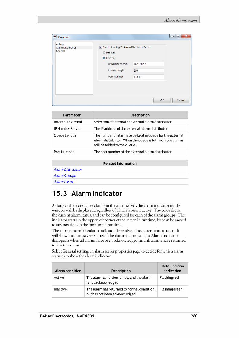
AlarmManagement
Parameter Description
Internal/External Selectionof internal or external alarmdistributor
IPNumber Server The IP address of theexternal alarmdistributor
Queue Length Thenumber of alarms tobe kept inqueue for theexternalalarmdistributor. When thequeue is full, nomore alarmswill beadded to thequeue.
PortNumber Theport number of theexternal alarmdistributor
Related information
AlarmDistributor
AlarmGroups
Alarm Items
15.3 Alarm Indicator
As long as there are active alarms in the alarm server, the alarm indicator notifywindowwill be displayed, regardless of which screen is active. The color showsthe current alarm status, and can be configured for each of the alarm groups. Theindicator starts in the upper left corner of the screen in runtime, but can bemovedto any position on themonitor in runtime.The appearance of the alarm indicator depends on the current alarm status. Itwill show themost severe status of the alarms in the list. TheAlarm Indicatordisappears when all alarms have been acknowledged, and all alarms have returnedto inactive status.SelectGeneral settings in alarm server properties page to decide forwhich alarmstatuses to show the alarm indicator.
Alarmcondition DescriptionDefault alarmindication
Active Thealarmcondition ismet, and thealarmis not acknowledged
Flashing red
Inactive Thealarmhas returned to normal condition,but has not beenacknowledged
Flashing green
Beijer Electronics, MAEN831L 280

AlarmManagement
Alarmcondition DescriptionDefault alarmindication
Acknowledged Thealarmcondition ismet, and thealarmis acknowledged
Flashing green
Normal The alarmhas returned to normal condition,andhasbeenacknowledged
-
Related information
General Settings
15.4 Alarm Items
Alarm items are added from theAlarm Items tab of the alarm server configurationpages.ClickAdd to define a new alarm.
Parameter Description
Name Symbolic name for thealarm itemthatwill show inanAlarmViewer.
Text Anoptional alarm text thatwill be shown in theAlarmViewer. Parts of the text canbemadedynamicby clicking...
Tag The tag (digital or analog),which generates the alarmwhen it assumes the specified status.
Expression See sectionExpressions
Condition Equal to/Notequal to: Thealarm is setwhen the valueof the tag is equal/not equal to the value specified in theTriggerValuefield.
Greater than/Less than: The alarm is setwhen thevalueof the tag is greater/less than the value specified in theTriggerValuefield.
Equal to greater than/Equal to less than: Thealarm is setwhen thevalueof the tag is equal to or greater/less thanthe value specified in theTriggerValuefield.
Rising/FallingEdge: The alarm is setwhen the specifiedtag goes to one/zero.
Beijer Electronics, MAEN831L 281
AlarmManagement
Parameter Description
TriggerValue Numeric value to trigger alarmwithwhen:
<tag value><condition><trigger value>= true.
History Specifieswhen the alarm is tobe removed fromthealarmlist. Checking this boxmeans that the alarmwill remainin the list until the list is full. Leaving it uncheckedmeansthat thealarmwill be removed fromthe listwhen it isacknowledgedandno longer active. IfAcknowledgeRequired is not checked, thealarmwill be removed fromthe list as soonas it is no longer active.
AcknowledgeRequired
Indicateswhether thealarm is to beacknowledgedornot. Checking theboxmeans that the alarmmust beacknowledged, leaving it uncheckedmeans that the alarmreturns to normal directlywhen thealarm status becomesinactive.
RemoteAcknowledge Adigital tag that acknowledges all thealarmwhen set to 1
RemoteAckExpression
See sectionExpressions
EnableDistribution Enables distributionof thealarmvia printer/SMS/e-mail.Only available if alarmdistribution is enabled for thealarmserver. If theEnableDistributionoption for the alarmgroup is checked, distribution of individual alarms in thegroupareautomatically enabled.
RepeatCount Toavoid that analarm that is triggered repeatedly resultsinmultiple entries in thealarm list,RepeatCount canbeused. Thecurrent alarmwill thenonly appear once in thealarm list, and thenumberof times thealarm is triggeredwill be included in thealarm text. It is also possible to showaCount column in theAlarmViewer. Theactive timecanbe showneither for thefirst timeor for the last time thealarmoccurred.
Action Makes it possible to configure oneormultiple actionswhenaparticular alarmevent occurs for the current alarm.
Note:Analarmcondition is triggeredbyafixedvalue. The trigger valuedefined for ananalogalarm tag cannotbecontrolled froma register. It is not supported to trigger alarmson intervals.
Related information
Actions andEvents forAlarm ItemsandAlarmGroups
15.4.1 Exporting and ImportingAlarmItems
Alarm items can be exported and imported using the Import/Export button in theAlarms configuration page. The procedure is similar to exporting and importingtags.
Beijer Electronics, MAEN831L 282

AlarmManagement
Related information
Importing andExportingTags
Tag Import Example
15.5 AlarmGroups
Alarms can be divided into groups, for example to indicate the priority of thealarms. One alarm group is defined by default.Color attributes can be individually set for each alarm group. Alarms can be sortedby group in theAlarmViewer.
15.5.1 DefiningAlarmGroups
Alarmgroups are added from theAlarmGroups tab of the alarm serverconfiguration pages.
Parameter Description
Name Anoptional name for thealarmgroup.
Text Anoptional text for thealarmgroup.
Colors Select foregroundandbackgroundcolor for each alarmstatus
RemoteAcknowledge
Adigital tag that acknowledges all thealarms in the groupwhen set to 1
RemoteAckExpression
See sectionExpressions
Beijer Electronics, MAEN831L 283

AlarmManagement
Parameter Description
EnableDistribution Enables distributionof thealarms in the group viaprinter/SMS/e-mail. Only available if alarmdistribution isenabled for the alarm server.
Action Makes it possible to configureoneormultiple actionswhenaparticular alarmevent occurs for the current alarmgroup.
Note:TheAlarmFilterwill revert to thedefault settings if theAlarmGroup is renamed.
Related information
Actions andEvents forAlarm ItemsandAlarmGroups
15.6 ActionsandEvents forAlarm ItemsandAlarmGroups
Actions can be configured for individual alarms or for alarm groups. One ormultiple actions can be configuredwhen a particular alarm event occurs for thecurrent alarmor alarm group.Actions for individual alarms are configured from theAction column for the alarmon theAlarm Items tab.Actions for alarm groups are configured from theAction column for the alarmgroup on theAlarmGroups tab.
15.6.1 Actions andEvents
Actions for the following alarm events and alarm group events can be configured:
AlarmAcknowledge
The specified actionswill be triggeredwhen the selected alarm/an alarm in theselected alarm group is acknowledged.
AlarmActive
The specified actionswill be triggeredwhen the selected alarm/an alarm in theselected alarm groupbecomes active.
AlarmEvent InfoRequested
The specified actions are triggeredwhen the Info button in theAlarmViewer ispressed.These actions are applied for the individual alarmfirst. If no action is specified forthe alarm, the actions are applied for the group. If no action is specified for thegroup, the actions are applied for the alarm server.
Beijer Electronics, MAEN831L 284
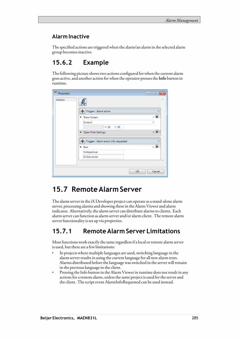
AlarmManagement
Alarm Inactive
The specified actions are triggeredwhen the alarm/an alarm in the selected alarmgroupbecomes inactive.
15.6.2 Example
The following picture shows two actions configured forwhen the current alarmgoes active, and another action forwhen the operator presses the Infobutton inruntime.
15.7 RemoteAlarmServer
The alarm server in the iXDeveloper project can operate as a stand-alone alarmserver, processing alarms and showing these in theAlarmViewer and alarmindicator. Alternatively, the alarm server can distribute alarms to clients. Eachalarm server can function as alarm server and/or alarm client. The remote alarmserver functionality is set up via properties.
15.7.1 RemoteAlarmServerLimitations
Most functionswork exactly the same regardless if a local or remote alarm serveris used, but there are a few limitations:• In projectswheremultiple languages are used, switching language in the
alarm server results in using the current language for all new alarm texts.Alarms distributed before the languagewas switched in the serverwill remainin the previous language in the client.
• Pressing the Info button in theAlarmViewer in runtime does not result in anyactions for a remote alarm, unless the same project is used for the server andthe client. The script event AlarmInfoRequested can be used instead.
Beijer Electronics, MAEN831L 285

AlarmManagement
• Unless the same project is used for the server and the client, filtering (pressingthe Filter button in the alarm viewer) can only bemade in runtime for remotealarms, since the remote servermay include e.g. alarm groups that aredifferent from the project inwhich the alarm viewerwas configured.
15.7.2 RemoteAlarmServerProperties
The following properties, located in theServerMode groupunder theSettingsbutton, need to be set up for the remote alarm server:
Property Description
Maximumnumberof alarmevents todistribute
Thenumber of events todistribute to the clients. Thenumberof distributedalarmsaffects performance.
ServerMode Thealarm server can assume the followingmodes:
Disabled: Thealarm server is disabledandnoalarmsareprocessed
Local: Thealarm serverprocesses alarmsof its own.
Remote: Alarmsaredistributed to remote clients.
Both: Thealarm server processes alarmsof its ownandalsodistributes themto remote clients
Server Port Any available port. Theport needs to correspond to theportsetting for the remotealarmclient.
15.7.3 RemoteAlarmClient
Theproperties for the remote alarm client are set by adding theAlarmDistributorViewer object, found in theObjects group under theHome tab.The settings are done in the PropertyGrid underExtended.
Property Description
Server address The IP address of the remotealarm server.
Server port Anyavailableport. Theport needs to correspond to theport setting for the remotealarm server.
Beijer Electronics, MAEN831L 286

AlarmManagement
15.8 AlarmDistributor
TheAlarmDistributormakes it possible to send alarmnotification via printer,SMSor e-mail. The function can be enabled internally in a project, or in anotheroperator panel that acts as a server towards several connected clients. Regardlessof acting as server or client, distributed alarms are saved temporarily in the localproject database to ensure that information is not lost in case of e.g. interruptedpower. After receiving alarms froma client, the serverwill send a confirmation tothe client. The alarmswill then be removed from the client’s database.
15.8.1 AlarmDistributionRoles
Using InternalAlarmDistributionServerFunctions(ActingasClient andServer)
The following actions are required for using distributed alarm functions in thecurrent project:
Action Component Location
Activatingdistribution ofalarms in theproject
AlarmDistributionServer
Insert ribbon tab
Enabling internaldistribution of alarms
AlarmServer Settingsbutton/AlarmDistributionproperties
Beijer Electronics, MAEN831L 287

AlarmManagement
Action Component Location
Enabling distribution ofalarmgroups or individualalarms
AlarmServer AlarmGroupsorAlarmItems tab
Configurationof alarmdistribution routes
AlarmDistributionServer
Receivers,AlarmFilterand Scheduler tabs
Configurationof alarmdistributiondevices
AlarmDistributionServer
ConfigureDistributionDevicesbutton (e-mail,printer and/or SMS)
UsingExternalAlarmDistributionServerFunctions(ActingasClient)
The following actions are required for using distributed alarm functions inanother operator panel/PCproject:
Action Component Location
Activatingdistribution ofalarms in theproject
AlarmDistributionServer
Insert ribbon tab
Enabling externaldistribution of alarms
AlarmServer Settingsbutton/AlarmDistributionproperties
Enabling distribution ofalarmgroups or individualalarms
AlarmServer AlarmGroupsorAlarmItems tab
CollectingAlarms forDistribution (Actingas Server)
The following actions are required for using distributed alarm functions inanother operator panel/PCproject:
Action Component Location
Activatingdistribution ofalarms in theproject
AlarmDistributionServer
Insert ribbon tab
Configurationof alarmdistribution routes
AlarmDistributionServer
Receivers,AlarmFilterand Scheduler tabs
Configurationof alarmdistributiondevices
AlarmDistributionServer
ConfigureDistributionDevicesbutton (e-mail,TCP server, printer and/orSMS)
15.8.2 AddinganAlarmDistributor
TheAlarmDistributor can be added to the project from the Insert ribbon tab. Theconfiguration pages are opened in the desktop area.
Beijer Electronics, MAEN831L 288

AlarmManagement
Route
A route defines a number of filtering rules for distribution of alarms. Multipleroutesmakes it possible to send different kinds of notifications to various receivers.
ReceiversTab
The receivers of distributed alarms for each route are set up on theReceivers tab.
AddressBook
Click on theAddress Bookbutton to enter names, e-mail addresses and/or phonenumbers of the persons that are to be available for selection for distributed alarmmessages.
TheShowSelection/ShowAll button can be used to set up a filter of displayeditems.
Beijer Electronics, MAEN831L 289
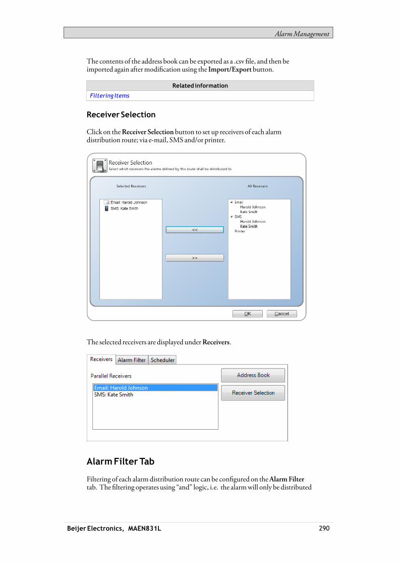
AlarmManagement
The contents of the address book can be exported as a .csv file, and then beimported again aftermodification using the Import/Exportbutton.
Related information
Filtering Items
Receiver Selection
Click on theReceiver Selection button to set up receivers of each alarmdistribution route; via e-mail, SMS and/or printer.
The selected receivers are displayed underReceivers.
AlarmFilterTab
Filtering of each alarmdistribution route can be configured on theAlarmFiltertab. The filtering operates using “and” logic, i.e. the alarmwill only be distributed
Beijer Electronics, MAEN831L 290
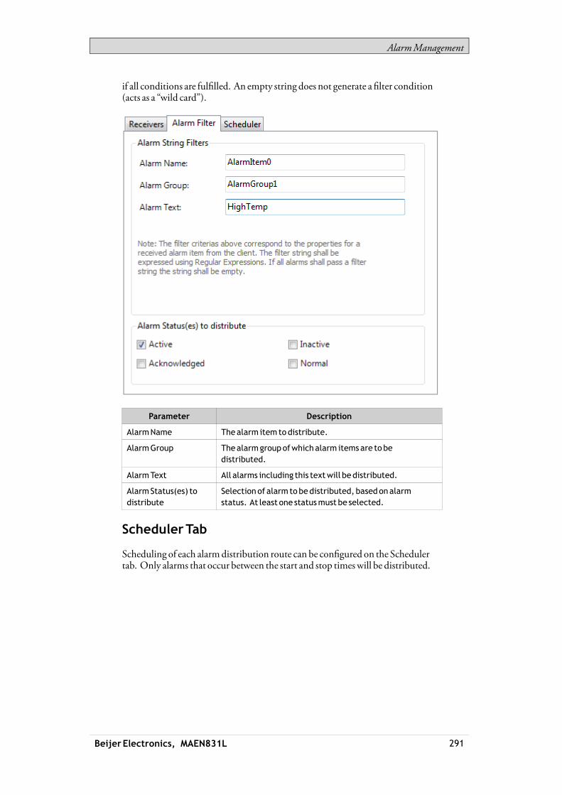
AlarmManagement
if all conditions are fulfilled. An empty string does not generate a filter condition(acts as a “wild card”).
Parameter Description
AlarmName Thealarm itemtodistribute.
AlarmGroup Thealarmgroupofwhichalarm itemsare tobedistributed.
AlarmText All alarms including this textwill bedistributed.
AlarmStatus(es) todistribute
Selectionof alarm tobedistributed, basedonalarmstatus. At least one statusmust be selected.
SchedulerTab
Scheduling of each alarmdistribution route can be configured on the Schedulertab. Only alarms that occur between the start and stop timeswill be distributed.
Beijer Electronics, MAEN831L 291
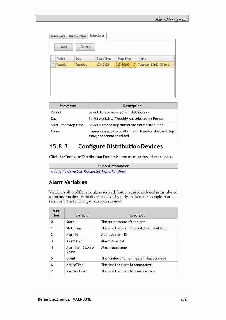
AlarmManagement
Parameter Description
Period Select daily orweekly alarmdistribution
Day Selectweekday, ifWeeklywas selected forPeriod
Start Time/StopTime Select start and stop timeof thealarmdistribution
Name Thename is automaticallyfilled inbasedon start and stoptime, andcannot beedited
15.8.3 ConfigureDistributionDevices
Click theConfigureDistributionDevices button to set up the different devices.
Related information
ModifyingAlarmDistribution Settings in Runtime
AlarmVariables
Variables collected from the alarm server definitions can be included in distributedalarm information. Variables are enclosed by curly brackets; for example “Alarmtext: {3}”. The following variables can be used:
Num-ber Variable Description
0 State The current state of the alarm
1 StateTime The time thealarmentered the current state
2 AlarmId Aunique alarm ID
3 AlarmText Alarm itemtext
4 AlarmItemDisplay-Name
Alarm itemname
5 Count Thenumber of times thealarmhasoccurred
6 ActiveTime The time thealarmbecameactive
7 InactiveTime The time thealarmbecame inactive
Beijer Electronics, MAEN831L 292
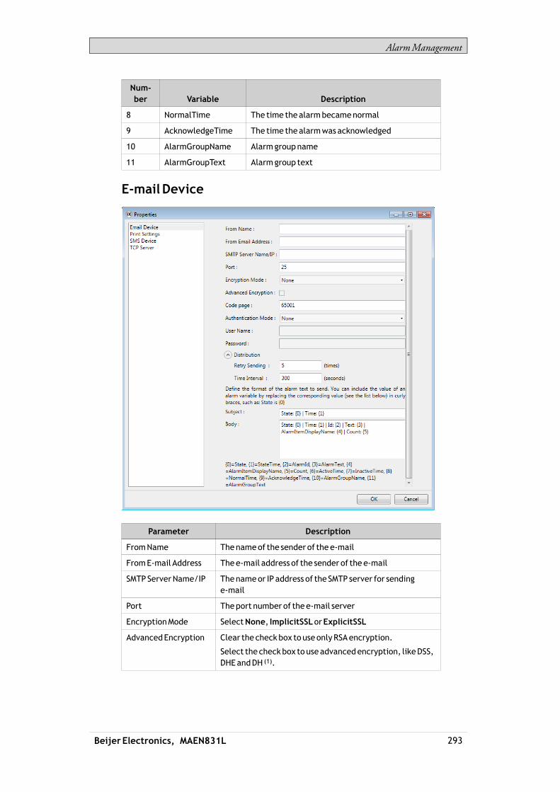
AlarmManagement
Num-ber Variable Description
8 NormalTime The time thealarmbecamenormal
9 AcknowledgeTime The time thealarmwasacknowledged
10 AlarmGroupName Alarmgroupname
11 AlarmGroupText Alarmgroup text
E-mail Device
Parameter Description
FromName Thenameof the senderof the e-mail
FromE-mail Address Thee-mail address of the sender of the e-mail
SMTPServerName/IP Thenameor IP address of the SMTP server for sendinge-mail
Port Theport number of thee-mail server
EncryptionMode SelectNone, ImplicitSSLorExplicitSSL
AdvancedEncryption Clear the checkbox touseonlyRSAencryption.
Select the checkbox touseadvancedencryption, likeDSS,DHEandDH (1).
Beijer Electronics, MAEN831L 293
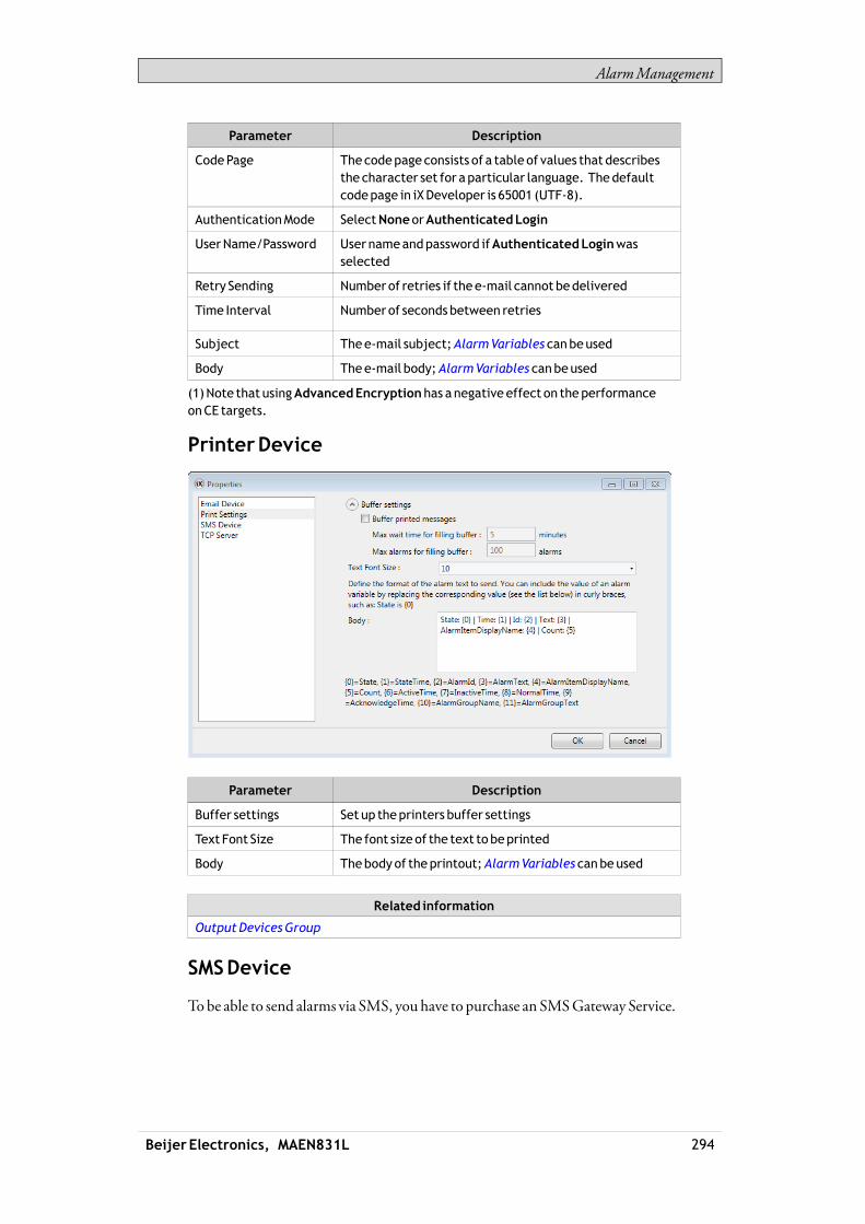
AlarmManagement
Parameter Description
CodePage Thecodepageconsists of a table of values that describesthe character set for aparticular language. Thedefaultcodepage in iXDeveloper is 65001 (UTF-8).
AuthenticationMode SelectNoneorAuthenticatedLogin
UserName/Password User nameandpassword ifAuthenticatedLoginwasselected
Retry Sending Numberof retries if thee-mail cannot bedelivered
Time Interval Numberof secondsbetween retries
Subject Thee-mail subject;AlarmVariables canbeused
Body Thee-mail body;AlarmVariables canbeused
(1)Note that usingAdvancedEncryptionhas anegative effect on the performanceonCE targets.
PrinterDevice
Parameter Description
Buffer settings Set up theprinters buffer settings
Text Font Size The font sizeof the text tobeprinted
Body Thebodyof theprintout;AlarmVariables canbeused
Related information
OutputDevicesGroup
SMSDevice
Tobe able to send alarms via SMS, youhave to purchase an SMSGateway Service.
Beijer Electronics, MAEN831L 294

AlarmManagement
Parameter Description
BasicURL forwebSMS TheURLconfiguration stringaccording to the SMSGatewayService supplier thatmust include twovariables: {0} fortelephonenumber and {1} for SMSbody
Retry Sending Numberof retries if the SMS cannot bedelivered
Time Interval Numberof secondsbetween retries
Body TheSMSbody;AlarmVariables canbeused
TCPServer
Define theTCP server port. Thismust correspond to the port defined for theAlarmDistribution settings for the alarm server.
15.9 AlarmDistributorViewer
TheAlarmDistributorViewer is a debug tool, used for test and verification of thealarmdistribution setup.Clicking the Settings button in runtimemakes it possible to edit the address bookandmake settings for alarmdistribution.
Beijer Electronics, MAEN831L 295

AlarmManagement
Related information
ModifyingAlarmDistribution Settings in Runtime
15.10AlarmViewer
TheAlarmViewer can be used to showmore detailed alarm information than thealarm indicator. Alarms presented in theAlarmViewer presents alarm texts fromthe alarm server. The alarm list shows the latest alarms. It is arranged in alarmgroup order.The default design of the alarm viewer depends on the size of the selected operatorpanel target, in order to allow full visibility and usability of the alarm viewer in thesmaller operator panels.Settings such as font andbuttonwidth are available in the Property grid.The colors of theAlarmViewer object can be set from the Property grid. Thecolors of the different alarm statuses are set in theAlarmServer settings.Ifmillisecond resolution is needed for the alarm timestamps, then this can beactivated using ShowMilliseconds in theGeneral tab in theRibbon or underExtended in the Property grid.
Note:Someof the color effects require thatVista Style is activatedunderExtended in theproperty grid (default setting).
Settings for theAlarmViewer are available from theGeneral ribbon tabwhile theobject is selected:
15.10.1 ButtonsGroup
Parameter Description
Position Controls towhichof theborders thebuttonswill lineup
Acknowledge Selected Acknowledges the selectedalarm in theAlarmViewer
AcknowledgeAll Acknowledges all alarms in all AlarmViewers
Clear Removes all alarms in all AlarmViewers
Beijer Electronics, MAEN831L 296

AlarmManagement
Parameter Description
Filter(1) Shows thefilter configurationdialog for the selectedAlarmViewer
Info Performs theaction set byAlarmEvent InfoRequested
Play/Pause Starts andpauses the selectedAlarmViewer
EnableContextMenu ShowsAlarmViewer commands in contextmenu in run-time
(1)Not supported in keyboardoperatedpanels
15.10.2 Display SettingsGroup
Parameter Description
ConfigureColumns Selectionandconfigurationof columns todisplay in run-time
Filter Settings(1) Filter alarm statuses todisplay in runtime
MaxNumberof Rows Themaximumnumberof alarms todisplay. If thenumberof alarmsdoes notfit in the object in runtime, scroll barswill bemadeavailable. If thenumber of alarmsexceedsthemaximumnumber, theoldest itemwill bedeleted.
ShowColumnHeaders Shows/hides thealarmviewers columnheaders
ShowSummary Shows status information in thebottomof theAlarmViewer
(1)Not supported in keyboardoperatedpanels
15.10.3 AlarmViewerCommands
In addition to using theAlarmViewer buttons, the same functions are availableusing actions.
Related information
Script
PropertyGrid
15.11AlarmManagement inRuntime
Alarmnotification can bemade in the followingways:
Alarm Indicator
AlarmViewer
Distribution via SMS, e-mail or printer via theAlarmDistributor
15.11.1 AlarmAcknowledgement
An alarm canbe acknowledged in the followingways:• right-clicking on the alarm line and selectingAcknowledge• selecting the alarm line and pressing on theAcknowledge Selected button
Beijer Electronics, MAEN831L 297
AlarmManagement
• pressing theAcknowledgeAll button to acknowledge all current alarms• script actions
Inactive alarms that have been acknowledged can be removed from the list bypressing theClear button.
15.11.2 Sorting
Pressing on the columnheading in runtime sorts the alarm list by that column.This pauses theAlarmViewer.
15.11.3 Filtering
Pressing the Filter button in theAlarmViewer opens a dialog that allows the userto enter a filtering profile to control which alarms to display in the alarm list.Filtering can bemade based on any combination of the following conditions:• Alarmgroup: The first column in the filter window shows the alarm group
name. Check theEnable box to show alarms from the group.• Alarm status: Displays alarmswith the status corresponding to the checked
status values.
Note:TheAlarmFilterwill revert to thedefault settings if theAlarmGroup is renamed.
15.11.4 Play/PauseButton
TheAlarmViewerwindow canbe paused frombeing updatedwith incomingalarms using the Play/Pause button. This allows the operator to inspect and sortthe list without interference from any incoming alarms. The list also pauseswhenan alarm is selected.The alarm list starts updating againwhen• the Play button is pressed• the operator changes screen and returns to the same screen (or goes to another
screen showing theAlarmViewer)• after a 5minute time-out
15.11.5 InfoButton
Pressing the Info button in theAlarmViewer triggers the action specified in theAlarmEvent InfoRequested group on theActions tab,when an item in the alarmserver is selected.Any action in the list can be selected.
Beijer Electronics, MAEN831L 298

AlarmManagement
This actionwill be applied for the individual alarmfirst. If no action is specified forthe alarm, the actionwill be applied for the group. If no action is specified for thegroup, the actionwill be applied for the alarm server.
Related information
AlarmGroups
AlarmConditions
AlarmEvent InfoRequested
15.11.6 ModifyingAlarmDistributionSettings inRuntime
It is possible to configure actions, or to use theAlarmDistributionViewer tomodify the address book and alarmdistribution settings in runtime.
Note:If theAlarmDistributionViewer or alarmdistribution actions are used in runtime, it ispossible that alarmdistribution settings havebeenmodified. Next timeyoudownloadaproject to theoperator panel, youwill get a notification, and selection to overwritepanel settings or not.
Related information
Address BookActionGroups
OutputDevicesActionGroups
Beijer Electronics, MAEN831L 299

SecurityManagement
16 SecurityManagement
Using security groups and passwords in the operator panelmakes it possible tocreate a security system for the project. Operators can easily be assigned differentauthorizations in the project to restrict access to objects and functions. Securitygroup information andpasswords are stored in the project database.It is not necessary to use this function if unrestricted access is acceptable. Thesecurity function is a predefined component of the Project Explorer.
16.1 General Security Settings
General settings for the security function are available by clicking on Security inthe Project Explorer, selecting theUsers tab and clicking the Settings button.
Parameter Description
Select action onaccess denied
Whenausers’s access rights arenot sufficient to e.g. modify anobject or carry out anaction, it is possible todisplay an accessdeniedmessageor openinga login dialog. SelectingNoneperformsnoaction.
Select visibility Whenauserwith insufficient access rights tries to affect anobject, it is possible to specify visibility for thoseobjects:
Disabled: Only userswith sufficient access rights can affectthe object. Theobject is visible, but disabled, for userswithinsufficient access rights.
Hidden: Only userswith sufficient access rights can see theobject. Theobject is invisible for userswith insufficient accessrights
Normal: Only userswith sufficient access rights canaffect theobject. Theobject looks normal for userswith insufficientaccess rights
Automatic logout Checking theboxmakes it possible to log out usersautomatically after a certain number ofminutes of inactivity.After anautomatic logout is executed, a screen jump to thestart screenwill be performed.
Beijer Electronics, MAEN831L 300
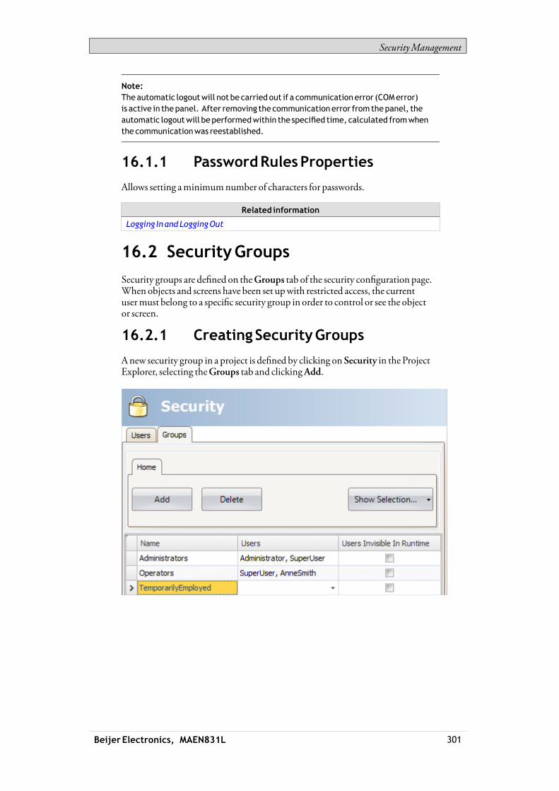
SecurityManagement
Note:Theautomatic logoutwill not be carried out if a communicationerror (COMerror)is active in thepanel. After removing the communicationerror fromthepanel, theautomatic logoutwill beperformedwithin the specified time, calculated fromwhenthe communicationwas reestablished.
16.1.1 PasswordRulesProperties
Allows setting aminimumnumber of characters for passwords.
Related information
Logging In andLoggingOut
16.2 SecurityGroups
Security groups are defined on theGroups tab of the security configuration page.When objects and screens have been set upwith restricted access, the currentusermust belong to a specific security group in order to control or see the objector screen.
16.2.1 Creating SecurityGroups
Anew security group in a project is defined by clicking on Security in the ProjectExplorer, selecting theGroups tab and clickingAdd.
Beijer Electronics, MAEN831L 301

SecurityManagement
Parameter Description
Name Anyalphanumeric string, beginningwith a letter (a-z, A-Z)
Users Selectionof users definedon theUsers tab tobe includedin thegroup
Users Invisible inRuntime
When thebox is checked, theusers in the current groupwill not be available for selection fromtheLogindialog inruntime. Itwill still be possible to type in theusernameandpassword to login.
operator panel targets only: In order to enable thepossibility tomanually enter a user nameandpassword, itis necessary to click the“Login” header on the Logindialogin runtime. Doing so and thenclickingon theUser—fieldwill present theuserwith a keyboardonwhichauser namecanbeentered.
16.3 Users
Users and passwords for login are defined on theUsers tab of the securityconfiguration page.
Parameter Description
Name Anyalphanumeric string, beginningwith a letter (a-z, A-Z)
Password Anyalphanumeric string;minimum lengthaccording toPasswordRulesproperties. Thepassword is converted toasterisks as you leave thepassword input cell.
Description Anoptional descriptionof theuser
Groups Selectionof security groups for theuser
It is also possible to addusers and change passwords directly in a running project,using theShowUsersDialog action.
Beijer Electronics, MAEN831L 302

SecurityManagement
16.3.1 Logging In andLoggingOut
The login dialog can be displayed in runtime by, for example, clicking a button,forwhich theLogin action has been specified. It is possible to change passwordfrom the login dialog.
The login dialog lists all users that have been configured for the current project,except for users in groups forwhichUsers Invisible inRuntimewas selected.It is also possible to configure a general behavior that brings up the login dialog anytime a user tries to affect an object that is notwithin the current user’s access rights.This behavior is configured from the Properties window for the Security function,and selectingShowLoginDialog for action on access denied.TheLogout action is used to perform a logout.Usersmay also be logged out automatically after a certain number ofminutes ofinactivity by configuringAutomatic logout in thePropertieswindow for theSecurity function.
Note:After logging out, the function ShowPrevious Screen for function keys and touchkeyswill be ignored. This is a security feature toprevent unauthorizedpersons fromaccessing screensprotectedbypasswords.
Related information
General Security Settings
ActionsRibbonTab
16.4 Object Security andVisibility
Object access can be restricted to a certain security group. Each security groupcontains a set of users and eachuser has an individual password. To be able tocontrol an object with a security setting, the usermust belong to the definedsecurity group, and has to login.Object security is controlled by selecting the object, and then opening theTag/Security group of theHomeorGeneral ribbon tabs.Whenno security is set for an object, the object will be available to everyone, i.e.loginwill not be requested.
Beijer Electronics, MAEN831L 303
SecurityManagement
Note:Security has higherpriority thandynamics.It is not possible to set security on function keys.
The visibility and behavior settings specified in the securitymanagerwill be usedwhen a security group is set but no explicit visibility is specified. The followingoptions can be set:
Visibility Description
Default Theobject looks normal and is visible for anyone.
Disabled Only users in the selected security groups canaffect theobject. Theobject is visible butdisabledandgreyedout,for userswith insufficient access rights.
Hidden Only users in the selected security groups can see theobject. Theobject is invisible for userswith insufficientaccess rights.
Normal Only users in the selected security groups canaffect theobject. Theobject looks normal for userswith insufficientaccess rights.
Related information
Tag/SecurityGroup
FunctionKeys
Screen Security
Beijer Electronics, MAEN831L 304
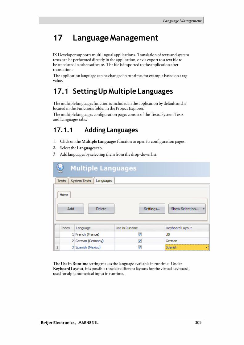
LanguageManagement
17 LanguageManagement
iXDeveloper supportsmultilingual applications. Translation of texts and systemtexts can be performed directly in the application, or via export to a text file tobe translated in other software. The file is imported to the application aftertranslation.The application language can be changed in runtime, for example based on a tagvalue.
17.1 SettingUpMultipleLanguages
Themultiple languages function is included in the application by default and islocated in the Functions folder in the Project Explorer.Themultiple languages configuration pages consist of theTexts, SystemTextsandLanguages tabs.
17.1.1 AddingLanguages
1. Click on theMultiple Languages function to open its configuration pages.2. Select theLanguages tab.3. Add languages by selecting them from the drop-down list.
TheUse inRuntime settingmakes the language available in runtime. UnderKeyboard Layout, it is possible to select different layouts for the virtual keyboard,used for alphanumerical input in runtime.
Beijer Electronics, MAEN831L 305

LanguageManagement
Note:The sizeof the virtual keyboards varybetween languages.Examples of keyboard sizes (the values are approximative)• Arabic: 18MB• Chinese - simplified: 12MB• Hebrew: 6MB• Korean: 21MB• Latin alphabets: 0.1MB.
Each added language is assigned an index number. Index number 0 is reserved forthe default language (the language that the applicationwas first created in).TheAdd andDelete buttons can be used to add and delete languages.TheSettings button allows connecting the language to a tag. Thismakes itpossible to change the project language based on a changed value.Use theShowSelection/ShowAll button if youwant to filter the languages in thecurrent view.
Related information
Virtual Keyboard
Filtering Items
17.2 SystemTexts
System texts belong to functions (e.g. alarm server or security), to the system(e.g. time zone) and to objects (e.g. buttons or sliders), excluding text that thedeveloper has entered.Select theSystemTexts tab in theMultiple Languages configuration pages to editsystem texts.Several preinstalled translations of the system texts are available for selection:• English• German• French• Brazilian Portuguese• Chinese, traditional• Chinese, simplified
Beijer Electronics, MAEN831L 306

LanguageManagement
Use theShowSelection/ShowAll button if youwant to filter the current view.The Import/Exportbutton can be used to export a system language to a text filefor translation, and then import the language after translation.
Note:Regional expressions for time, date, andweekdays arebydefault equal to the settingsin the systemaccount, but can to someextent be changed in theDate, TimeandRegionGroupunder the SystemRibbon tab.
Related information
Filtering Items
Exporting Languages
Importing Languages
Date,Time,andRegionGroup
17.3 UserTexts
Texts that have been added to objects by the developer are available from theTexts tab in theMultiple Languages configuration pages. The texts in the defaultlanguage can be edited aswell.
Beijer Electronics, MAEN831L 307

LanguageManagement
Use theShowSelection/ShowAll button if youwant to filter the current view.The Import/Exportbutton can be used to export a system language to a text filefor translation, and then import the language after translation.
Note:Whenanobject is connected to a text in theText library, theobject’s internaldenomination (that is not displayed in runtime)will bepresented in grey color in theTexts list, to indicate that editing the textwill not affect the runtimeproject.
Related information
Filtering Items
Exporting Languages
Importing Languages
Text Library
17.4 Text ID
TheText ID function is available from theText IDs tab on theMultipleLanguages configuration page.To enable theText ID function, check the “Text IDs enabled” checkbox on theText IDs tab.
Beijer Electronics, MAEN831L 308

LanguageManagement
TheText IDs tab consist of the following columns: Text ID,DefaultText and onecolumn for each language. The text in the columnDefault Text corresponds tothe default language used in iXDeveloper.ClickingAdd adds a rowwith aText ID that is equal to the highest existingTextIDplus 1.Use theShowSelection/ShowAll button if youwant to filter the current view.The Import/Exportbutton can be used to export a system language to a text filefor translation, and then import the language after translation.
Related information
ScreenGroup
Filtering Items
Exporting Languages
Importing Languages
17.4.1 Text IDBrowser
If theText ID function is enabled, all text box controls in iXDeveloper, includingtexts used in iXRuntime,will be replacedwith theText IDbrowser control.TheText IDs are accessed from apopup list by clicking the combobox arrownextto theText IDbrowser control.TheText IDbrowser consists of two tabs, one for usingText ID and one for usingDynamicText ID.• If the requestedText ID text is known in iXDeveloper, theText ID tab should
be used.• If the requestedText ID text is to be decided dynamically in runtime, then the
DynamicText ID tab should be used.
Text ID
The popup list consist of the following columns: Text ID,Default Text and onecolumn for each language. Right-clicking the columnheader opens up a contextmenu that lists all available columns. The contextmenu offers a possibility toconfigurewhich columns to be displayed in the popup list.
Beijer Electronics, MAEN831L 309

LanguageManagement
Parameter Description
Add Adds a rowwithaText ID thatequals to thehighest existingText IDplus 1
Reset Removes theText ID connection and the text falls back tothepreviously unconnected text
OK Connects theobject text to the selectedText ID
Cancel Closes thepopup list. No changes aremade.
When an object is connected to aText ID, the displayed text in theText IDbrowser control will be presented in the followingmanner:“Text ID –Text”Text corresponds to the default language used in iXDeveloper.
When opening the popup list, the text field acts as a filter for the popup list.The object itself will only show the corresponding text, withoutText ID, whichis disabled for editing.When the language in iXDeveloper or in iXRuntime is changed, a text connectedto aText IDwill be updated to the corresponding text entered in theText IDs tab.DynamicText ID
TheDynamicText ID tab consist of two tabs—Tags andAliases—and acts as anormal tag/alias selector.
Beijer Electronics, MAEN831L 310

LanguageManagement
In addition, it is also possible for the graphical components to set aDefaultValueUsed inDesignMode. This valuewill be displayed in the object in designtime,but not be used in runtime.
Parameter Description
Add Adds a tag/alias
Reset Removes theDynamicText ID connection and the textfalls back to thepreviously unconnected text
OK Connects theobject text to the selected tag/alias
Cancel Closes thepopup list. No changes aremade.
When an object is connected to a tag, the displayed text in theText IDbrowsercontrolwill be presented as “TagName”, whereTagName is the name of the tag.When an object is connected to an alias, the displayed text in theText IDbrowsercontrolwill be presented as “#AliasName”, whereAliasName is the name of thealias.When configured, the tag value in runtime represents the key (Text ID) to theTextID table. The displayed text is the corresponding translation for current languagefor the given key (Text ID). If the tag value is not found as a key in theText IDtable, an empty text is displayed.
17.5 AutomaticTranslation
iXDeveloper includes a translation tool that usesMicrosoft Translator (www.mi-crosoft.com/translator) orGoogleTranslate (translate.google.com) to offer quicktranslations of user-defined texts or system texts. Due to license requirements youhave to sign up for an account at one of the translation providers to get the required
Beijer Electronics, MAEN831L 311

LanguageManagement
keys. If no keys are entered iXDeveloper usesMicrosoft Translator to translate alimited number ofwords permonth.
Note:Automatic translations provide limited functionality; especially combinationofwordsorwordswith synonymsmaybe returnedas incorrect translations.
The translation tool is available by clickingTranslate on theTexts or SystemTextstabs of theMultiple Languages configuration pages. Each language is translatedseparately.
Beijer Electronics, MAEN831L 312

LanguageManagement
Parameter Description
TranslationProvider Select translationprovider amongavailable providers.
MicrosoftTranslator C-lient Id
TypeaClient Id. Youneed to get anaccount onWindowsAzureMarketplaceand subscribe toMicrosoft TranslatorAPI to get aClient IdandaClientSecret.
MicrosoftTranslator C-lient Secret
TypeaClient Secret key. Youneed to get anaccountonWindowsAzureMarketplaceand subscribe toMicrosoft TranslatorAPI to get aClient IdandaClientSecret.
Googleuser Key TypeaPublic API Access Sever key. Youneed to create aGoogleDevelopers account anduse theproductGoogleTranslateAPI to get the key.
SaveKey Saves theMicrosoft Translator Id andClient Secret or theGoogleuser Key in your userprofile on thedevelopmentPC.
Translatate from Selectionof source language for the translationoperation;thedefault language (reference language) or oneof thelanguages that havebeenadded to theproject.
Translate to Selectionof target language for the translationoperation.
ReferenceLanguage Select reference language; i.e. the language inwhich theprojectwas created.
Only translate itemsthathavenot yet beentranslated
Clear the checkbox to replace also already translateditems in theproject.
Note:Since the translation tool accesses online translation providers, the translationoperationmay sometimesbepausedor delayeddue toanexcess of onlineusers.
17.6 ExportingLanguages
Languages can be exported to a text file for e.g. translation.1. SelectExport from the Import/Export button.2. Specify format, location, delimiter (for text file format) and language
selection, and clickOK.
Beijer Electronics, MAEN831L 313

LanguageManagement
Parameter Description
Format Select format of theexportedfile; textfile or Excelfile.
Path Browse to the location for theexportedfile
Delimiter IfTextfile formatwas selected, select delimiter fromthedrop-down list; comma, semicolon, spaceor tab
Languages Selectwhich languages to export
The exported filewill also include the default language.
Note:Todisplay certain characters (such asChineseorArabic) correctly in Excel selectUnicode (UTF-8) in the Excel import dialog.
Note:In order to import or export .xls-filesMicrosoft Excelmust be installed.
17.7 ImportingLanguages
After translation or other editing, the updated language file can be imported tothe project again.1. Select Import from the Import/Export button.2. Specify location and language selection, and clickOK.
Beijer Electronics, MAEN831L 314

LanguageManagement
Parameter Description
Format Select format of thefile to import; textfile or Excelfile.
Path Browse to the locationof thefile to import
Languages Selectwhich languages to import
Import Strategy SelectingKeyperforms the import according to theDesignerandObject columns in themultiple languagesconfigurationpage. ReferenceTextperforms the importaccording to theText column. If youhavechangedthe texts of thedefault language after exporting thelanguages, it is recommended to selectKey.
The imported filewill also include the default language.
Note:Make sure tomakeabackupcopyof theproject before importing languages, in casetherearemismatchesbetween theexisting and the imported languages.
Note:In order to import or export .xls-filesMicrosoft Excelmust be installed.
Beijer Electronics, MAEN831L 315

Audit Trail
18 AuditTrail
TheAudit Trail functionmakes it possible to track operator actions.TheAudit Trail database can be exported in csv format using theDatabase Exportaction. It is recommended to use the database exportmethod rather than thebackupmethod.
Related information
DatabaseExport
18.1 LoggingStrategies
Tomeet FDA (Food andDrugAdministration) demands, it is possible to logactions in a strictmanner. FDA logging implies that no log entries will everbe overwritten. If the size of the audit trail database is close to being exceeded(approximately 80%of the limit), a notificationwindowwill be displayed,wherethe user is warned, anddemanded to export the data. Alternatively, the size oftheAudit Trail database can be increased. If the limit of the database is exceeded,the logging is terminated and the operator panelwill be blocked for any furtheroperator actions. This is indicated by an errormessage.With circular buffering, the oldest log entry is overwrittenwhen the database isfull. Nowarningmessage is displayedwhen reaching the limit of the database.The database can be exported using an action, regardless of logging strategy.The log entries are saved in theAudit Trail database, and the information can bedisplayed using theAudit Trail Viewer.
18.2 Using theAuditTrail Function
The function is enabled by selectingAuditTrail from the Insert ribbon tab. Theconfiguration page opens in the desktop area. All actions available for loggingare listed. It is possible to log all or only some actions. It is also possible to log tagchanges only (without logging actions).
Beijer Electronics, MAEN831L 316

Audit Trail
Parameter Description
LogAll/LogNone Click thebuttons toquickly select all or noactions fromthe list
Logging strategy Select FDAorCyclic Buffering
Max sizeof database Themaximumsizeof theAudit Trail database
Value change on tags, performed by user actions, can be logged by selectingLog toAuditTrail in the tags configuration page. This option is enabled only if the audittrail function is activated in the project.
Related information
Others inAddingTags section
18.2.1 AuditTrail Description
It is possible to add a description for each object that is logged to theAuditTraildatabase using the PropertyGrid.
The descriptionwill be saved to theDescription columnof theAudit Traildatabase, and is limited to 255 characters.
Beijer Electronics, MAEN831L 317
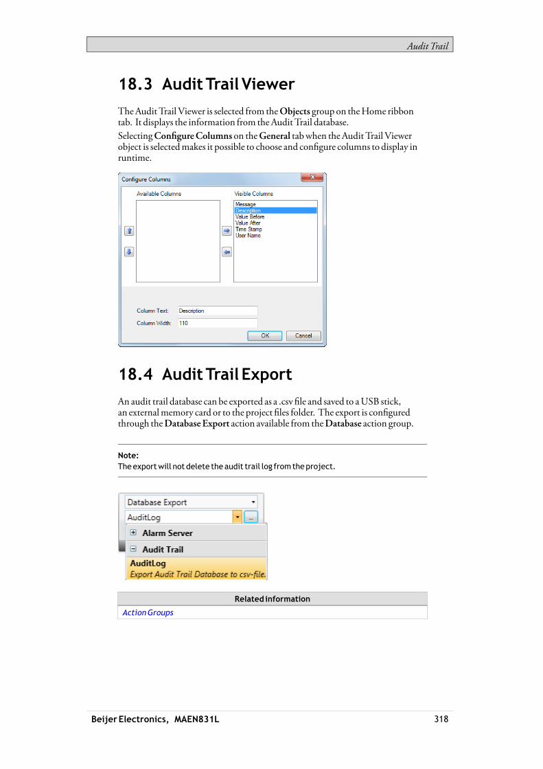
Audit Trail
18.3 AuditTrail Viewer
TheAudit Trail Viewer is selected from theObjects group on theHome ribbontab. It displays the information from theAudit Trail database.SelectingConfigureColumns on theGeneral tabwhen theAudit Trail Viewerobject is selectedmakes it possible to choose and configure columns to display inruntime.
18.4 AuditTrail Export
An audit trail database can be exported as a .csv file and saved to aUSB stick,an externalmemory card or to the project files folder. The export is configuredthrough theDatabase Export action available from theDatabase action group.
Note:Theexportwill not delete theaudit trail log fromtheproject.
Related information
ActionGroups
Beijer Electronics, MAEN831L 318

Audit Trail
18.4.1 AuditTrail Export froman iXpanelTarget
It is possible to select export toUSB, export to externalmemory card or export totheProject Files folder, and also setting another name of the export file.It is also possible to select the requested delimiter in the .csv file (commaorsemicolon).
18.4.2 AuditTrail Export fromaPCTarget
It is possible to selectBrowse and Select an export path,Export to Path or theExport toProject Files folder, and also setting another name of the export file.TheBrowse andSelect an export path option allows browsing for desired exportdestination in runtime. Thismay be useful if available folders in runtime areunknownwhendesigning the project.
Beijer Electronics, MAEN831L 319

Audit Trail
Select theExport toPath optionwhen youwant to set the pathwhen designing theproject. If the pre-defined path is not valid in runtime, the operatormay browsethe PC environment by clicking a browse button.It is also possible to select the requested delimiter in the .csv file (commaorsemicolon).
Beijer Electronics, MAEN831L 320

Text Library
19 TextLibrary
With the text library function, text tables can be created,where values are linkedto texts. The text library function can be used for presentation of each sequencestep in sequence control. Another possible application is to present error codes,where an analog signal generates error codes connected to texts in a text library.The function can also be used to give analog values specific values, depending onthe selected texts.The text library function is activated by selecting it from the Insert ribbon tab.
Texts and groups can be added from theAdd button.It is also possible to add start and end values for eachmessage, thatmakes the textin the connected object change depending on the value of the tag.
Note:TheStartValueandEndValuecanonlybegiven as integers. This could result inproblemsupdating the textwhen the input value is enteredwithdecimals, especially ifthe input value jumps in andout of the given range. If this is the case, use theConfigureText function instead. This is available under theGeneral tabwhen theobject isselected.
Note:Adefault text that has beenentered inConfigureTextwill not bepresentedoutsidea range that hasbeendefined in theTextLibrary. In this case, useConfigureText todefineall text presentations for theobject.
Related information
HMIControls
Beijer Electronics, MAEN831L 321
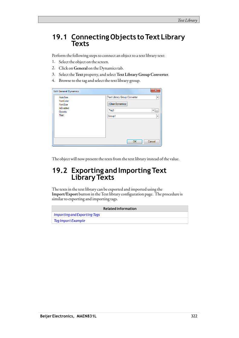
Text Library
19.1 ConnectingObjects toTextLibraryTexts
Perform the following steps to connect an object to a text library text:1. Select the object on the screen.2. Click onGeneral on theDynamics tab.3. Select theText property, and selectText LibraryGroupConverter.4. Browse to the tag and select the text library group.
The object will nowpresent the texts from the text library instead of the value.
19.2 Exportingand ImportingTextLibraryTexts
The texts in the text library can be exported and imported using theImport/Export button in theText library configuration page. The procedure issimilar to exporting and importing tags.
Related information
Importing andExportingTags
Tag Import Example
Beijer Electronics, MAEN831L 322
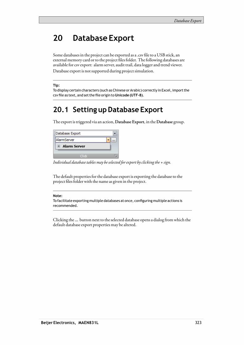
Database Export
20 DatabaseExport
Somedatabases in the project can be exported as a .csv file to aUSB stick, anexternalmemory card or to the project files folder. The following databases areavailable for csv export: alarm server, audit trail, data logger and trend viewer.Database export is not supported during project simulation.
Tip:Todisplay certain characters (such asChineseorArabic) correctly in Excel, import thecsvfile as text, and set thefile origin toUnicode (UTF-8).
20.1 SettingupDatabaseExport
The export is triggered via an action,Database Export, in theDatabase group.
Individual database tablesmay be selected for export by clicking the + sign.
The default properties for the database export is exporting the database to theproject files folderwith the name as given in the project.
Note:To facilitateexportingmultiple databases at once, configuringmultiple actions isrecommended.
Clicking the ... button next to the selected database opens a dialog fromwhich thedefault database export propertiesmay be altered.
Beijer Electronics, MAEN831L 323

Database Export
20.1.1 DatabaseExport fromoperatorpanelTarget
It is possible to select export toUSB stick or externalmemory card, and also settinganother name of the export file. Leaving theOverwrite box unchecked adds dateand time to the export file name, thus avoiding overwriting an existing export file.
Note:Whenexporting fromaCE target (iXTxAor iXTxBoperator panel) note that theoptionsExternalMemoryCardandUSBarenot available onaPC. If theTargetType in theproject is changed fromaCE target to aPC the selection is clearedandhas tobemadeagain.
20.1.2 DatabaseExport fromPCTarget
Beijer Electronics, MAEN831L 324
Database Export
It is possible to set another name of the export file. Leaving theOverwriteboxunchecked adds date and time to the export file name, thus avoiding overwritingan existing export file.TheBrowse andSelect anExport Pathoption allows browsing for desired exportdestination in runtime. Thismay be useful if available folders in runtime areunknownwhendesigning the project.Select theExport toPath optionwhen youwant to set the pathwhen designing theproject. If the pre-defined path is not valid in runtime, the operatormay browsethe PC environment by clicking a browse button.
Note:Whenexporting fromPC toaCE target (iXTxAor iXTxBoperator panel) it is not possibleto use paths to anExternalMemoryCardor aUSB. If theTargetType in theproject ischanged fromaPC toaCE target the selection is clearedandhas tobemadeagain.
Related information
ActionsRibbonTab
Simulate
MultipleActions
Beijer Electronics, MAEN831L 325
iX panel System Software
21 iXpanel SystemSoftware
In the operator panel, iXRuntime comes pre-loaded ondelivery.iXRuntime can be replaced, that is, updated to a newer version, either via PCorvia externalmemory card.An Image Loader is used to download systemprograms to the operator panel via aPC.The Image Loader is available from theweb site.
Note:The ImageLoader requires that .NETFramework2.0 is installedon thePC.
Note:Whenupdating anoperatorpanel, it is important to ensure that power is notinterruptedduring the transfer.It is not recommended todowngrade the systemsoftware to aprevious version.
21.1 WelcomeScreen
When the operator panel is started, thewelcome screen is displayed. Thefollowing items about the operator panel are listed:• Size of internalmemory card, if applicable• IP address• Image version
If there is a project in the panel, it will be loaded automatically.If there is no project in the panel, touching the screenwill display the Servicemenu.If there is an SDcard inserted into the panel, and the project on the SD card differsfromwhat is saved in the operator panel, then the user is asked if the project andIP-settings should be restored.
Related information
ServiceMenu
21.2 ServiceMenu
The servicemenu for the operator panel can be accessed before a project isdownloaded.
21.2.1 ServiceMenu inanEmptyPanel
Whenno project is loaded in the panelmemory, the panel will boot, displaying theWelcome screen.• Press anywhere on the panel display to enter the servicemenu.
Beijer Electronics, MAEN831L 326

iX panel System Software
21.2.2 ServiceMenu in iXTxA/iXTxBPanels
Perform the following steps to enter the servicemenu:1. Apply power to the panel.2. When the hourglass appears, press a finger on the screen and hold for
approximately 20 seconds.3. If the servicemenu is password protected, youwill be prompted for a pin code.
Enter pin code.4. The touch calibration screenwill display the followingmessage:
“Tap anywhere on screen or touch calibrate will start in 10 seconds.”5. Press finger once again to enter the servicemenu.
21.2.3 ServiceMenuOptions
IP Settings
Select to obtain an IP address automatically viaDHCP, or specify an IP address.The IP address can also be set during project transfer.For panels with twoEthernet ports, select port according to the illustration below.
The port that is currently connected is recognized by a *.
Date/Time
Use theDate/Time Settingsdialog to set the time zone, date and time for thepanel.
EraseProject
The erase functionwill detect if the project is located in the panelmemory or on amemory card. PressingEraseProjectwill completely remove the project and all itscomponents from the panelmemory/thememory card.
CopyProject
SelectingCopyProjectwill copy a project from a connectedmemory card to thepanelmemory.If there is already a stored project in the target panel, the copy commandwill resultin a dialog asking if a backup of the existing project should be saved on thememorycard.
Beijer Electronics, MAEN831L 327

iX panel System Software
If IP settings are stored in thememory card, a dialogwill appear, asking if the IPsettings should be applied to the target panel. It is necessary to reboot the panel forthe IP address to be updated.The copy function can also be used to copy a project from aUSBmemory,howeverwithout the possibility to transfer IP settings.
TouchCalibrate
SelectTouchCalibrate if the touch screen needs to be calibrated. Follow theinstructions on the screen to perform a calibration.
Close
PressClose to exit the servicemenu.
21.3 iXpanelUpgrade
The operator panel can be upgraded using the Image Loader application.
21.3.1 Requirements
Updating of the operator panel systemprogram requires the following:• APCwith Image Loader application.• AnEthernet connection between the PC and the operator panel.• The operator panel IP address.• The Image file from theweb site.
21.3.2 Transfer Image
1. Double-click on the executable Image Loader file to start the transfer program.2. Follow the instructions.
Transferprocedure in iXTxApanels
The image transfer procedure is completelymenu-driven. The operator panelwill be ready for transfer directly afterwards, provided that all steps are performedand completed.The following steps outline the transfer procedure:1. Disconnect the power supply from the panel.2. Press a finger on the screen and apply power3. Start the Image loader software on the computer, and follow the instructions
on screen.4. Select the operator panel to upgrade by entering its IP address.5. ClickUpgrade.6. When the upgrade is finished, disconnect power from the operator panel.7. Reconnect power to the operator panel.8. Once the systemfiles have been updated, a project can be downloaded to the
operator panel.
Beijer Electronics, MAEN831L 328
iX panel System Software
Note:Whenupdating anoperatorpanel, it is important to ensure that power is notinterruptedduring the transfer.
Transferprocedure in iXTxBpanels
The image transfer procedure is completelymenu-driven. The operator panelwill be ready for transfer directly afterwards, provided that all steps are performedand completed.The iXTxBpanels can be updated either by using aUSBflash drive, or using theEthernet connection to transfer the files.
Transferprocedureusing aUSBflashdrive
1. Start the Image loader software on the computer.2. Plug an emptyUSBflash drive into the computer running the Image loader
software.3. Select theUSBflash drive in the Image loader software.4. ClickCreate.5. Disconnect power from the operator panel6. Plug theUSBflash drive into the operator panel.7. Reconnect power to the operator panel.8. Once the systemfiles have been updated, any existing project in the panelwill
be started.
Note:Whenupdating anoperatorpanel, it is important to ensure that power is notinterruptedduring the transfer.
Transferprocedureusing theEthernet connection
1. Start the Image loader software on the computer.2. Select the operator panel to upgrade by entering its IP address.3. ClickUpdate. Any project running in the panelwill be stopped, and the
update sequencewill begin.4. When the upgrade is finished, disconnect power from the operator panel.5. Reconnect power to the operator panel.6. Once the systemfiles have been updated, any existing project in the panelwill
be started.
Note:Whenupdating anoperatorpanel, it is important to ensure that power is notinterruptedduring the transfer.
Beijer Electronics, MAEN831L 329

Multiple Controllers
22 MultipleControllers
It is possible to usemultiple drivers with one operator panel. Thismeans that theoperator panel can communicatewith different controllers simultaneously. Thecontrollers can be connected to the serial ports on the operator panel and via theEthernet port.
Note:If the same tag is connected to addresses inmore thanoneactive controller, there is noway to control fromwhich controller the value is read in runtime.
22.1 AddingaController
Click onTags in the Project Explorer, select theController tab and clickAdd toadd a new controller in the current project, and selectwhich controllermodel anddriver that is to be used.Tags are added and controller is selected on theTags tab.
Related information
Adding aController
Beijer Electronics, MAEN831L 330

Multiple Controllers
22.1.1 Addressing
Addressing of the tags in the controllers is carried out according to the help filefor each driver.When assigning a tag to an object, all tags, regardless of controller connection, areavailable for selection.
22.1.2 Examples
The following examples show configurationswheremultiple drivers are used inthe operator panel.
The operator panel communicatingwith one controller and one frequency converter.
Beijer Electronics, MAEN831L 331

Multiple Controllers
The operator panel communicating in series with one controller via Ethernet andwithcontrollers of anothermake.
The operator panel communicatingwith two controllers of differentmakes viaEthernet.
Beijer Electronics, MAEN831L 332

Troubleshooting
23 Troubleshooting
This section describes tools to use in case of unexpected behavior in iXDeveloper.
23.1 ProjectBuildFailure
If project build fails, check that the absolute path to the project, including itscomponents, does not exceed 260 characters.
23.2 BackupProject Issues
Make sure that project that is fetched using theBackup command is identical tothe current iXDeveloper project; i.e. has the samename and is of the same size.
Related information
UploadDatabase
23.3 InvalidNames
If using systemdevice nameswhennaming objects such as controllers, screens,recipemanagers, data loggers and scriptmodules, an errormessagewill bedisplayed, stating that this is an invalid name. Examples of systemdevice names:AUX,COM1,CON,LPT3,NUL, PRN.
Related information
NameGroup
23.4 AdobeReadernotRecognized
In order for the PDFViewer object to recognize that AdobeReader is installed inthe development PC aswell as in the target, the settingDisplay PDF in browserhas to be enabled inAdobeReader.1. OpenAdobeReader and selectEdit/Preferences/Internet.2. Check theDisplay PDF in browserbox.
23.5 ExpressionCannotBeFound
If an error indicating that an expression cannot be found is generated at projectvalidation,make sure that objects inserted from theComponent library usesglobal expressions only.
Related information
Using Expressions
Beijer Electronics, MAEN831L 333
Troubleshooting
23.6 Performance IssueRelated toGraphicsCard
Whendesigning iXDeveloper projects, theCPU loadmay suddenly increasewhen performing actions such asmoving objects on the screen or hovering overbuttons, depending onwhich graphics card is used.This problemmay be solved by adjusting the hardware acceleration of the graphicscard.InWindowsXP, follow the steps below tomake needed adjustments:1. Double-click on theDisplay icon in theWindows control panel.2. Select the Settings tab and click on theAdvanced button.3. Select theTroubleshoot tab and decrease or turn off the hardware acceleration
by dragging the slider.
Note:Should youexperienceproblemswith the graphic rendering,make sure the latestgraphical driver is used. If the latest graphical driver is usedand rendering issues stilloccur, upgrade to abetter graphics card.
Related information
SystemRequirements andLimitations
23.7 ErrorRelated toThirdPartyControls
Whenopening a project including third party controls, the third party controlshave to be included in the iXDeveloper third party control folder. Otherwise theprojectmay terminate, or unexpected errormessagesmay be displayed.When referencing third-party assemblies (.dll files),make sure not to place twofileswith the same fully qualified assembly name in the same folder, otherwiseerrorsmay occur.
23.8 Performance IssueWhenNavigating in ScriptTreeView
If you areworkingwith a large iXDeveloper project, especially a project withmany tags and alarms, youmay find that navigating the script tree view is slow.The performance can be improved by saving the project.
Related information
Script
Beijer Electronics, MAEN831L 334