pro-2200 two reader module installation manual two reader module installation manual part number:...
TRANSCRIPT

PRO-2200Two Reader ModuleInstallation Manual
Part Number: PRO22R2
TD1143 rev 0501
A division of Northern Computers, Inc.


PRO-2200 Two Reader Module PRO22R2 3Installation Guide
Contents
Warnings and Cautions ........................................................................................ 4Disclaimer........................................................................................................... 6Product Liability; Mutual Indemnification................................................................ 6Unpacking Procedure ........................................................................................... 6Shipping Instructions ............................................................................................ 7Limited Warranty ................................................................................................. 7Confidentiality ..................................................................................................... 8Description .......................................................................................................... 9Set Up ................................................................................................................ 9LED Operation .................................................................................................. 11Power................................................................................................................ 11Communications ............................................................................................... 11Reader Wiring ................................................................................................... 12Alarm Contact Wiring ........................................................................................ 13Control Output Wiring ....................................................................................... 13Mounting Options ............................................................................................. 14Suggested Installation Sequence ......................................................................... 14Specification...................................................................................................... 15Wiring Diagram for Connectors 1 through 7 ........................................................ 16Wiring Diagram for Connectors 6 through 10 ...................................................... 17

4 PRO-2200 Two Reader Module PRO22R2Installation Guide
Warnings and Cautions
WARNING
Before installation, TURN OFF the external circuit breaker which supplies power to thesystem.
Before connecting the device to the power supply, verify that the output voltage is withinspecifications of the power supply.
Do not apply power to the system until after the installation has been completed.Personal injury or death could occur, and the equipment could be damaged beyondrepair, if this precaution is not observed!
WARNING
Fire Safety and Liability Notice
Never connect card readers to any critical entry, exit door, barrier, elevator or gatewithout providing an alternative exit in accordance with all fire and life safety codespertinent to the installation. These fire and safety codes vary from city to city and youmust get approval from local fire officials whenever using an electronic product to controla door or other barrier. Use of egress buttons, for example, may be illegal in some cities.In most applications, single action exit without prior knowledge of what to do is a lifesafety requirement. Always make certain that any required approvals are obtained inwriting. DO NOT ACCEPT VERBAL APPROVALS, AS THEY ARE NOT VALID.
Engineered Systems never recommends using the PRO-2200 or related products as aprimary warning or monitoring system. Primary warning or monitoring systems shouldalways meet local fire and safety code requirements. The installer must also test thesystem on a regular basis by instructing the end user in appropriate daily testing proce-dures. Failure to test a system regularly could make installer liable for damages to the enduser if a problem occurs.
WARNING
EARTH ground all enclosures, for proper installation.
WARNING
Use suppressors on all door strikes. Use S-4 suppressors for installation. EngineeredSystems recommends only DC strikes.
The information in this document is subject to change without notice.

PRO-2200 Two Reader Module PRO22R2 5Installation Guide
CAUTION
IF ANY DAMAGE TO THE SHIPMENT IS NOTICED, A CLAIM MUST BE FILED WITHTHE COMMERCIAL CARRIER RESPONSIBLE.
CAUTION
Electro-static discharge can damage CMOS integrated circuits and modules.
To prevent damage always follow these procedures:
Use static shield packaging and containers to transport all electronic components,including completed reader assemblies.
Handle all ESD sensitive components at an approved static controlled workstation. Theseworkstations consist of a desk mat, floor mat and an ESD wrist strap. Workstations areavailable from various vendors.
NOTICE
This equipment has been tested and found to comply with the limits for a Class A digitaldevice, pursuant to part 15 of the FCC Rules. These limits are designed to providereasonable protection against harmful interference when the equipment is operated in acommercial environment. This equipment generates, uses, and can radiate radio fre-quency energy and, if not installed and used in accordance with the instruction manual,may cause harmful interference to radio communications. Operation of this equipment ina residential area is likely to cause harmful interference in which case the user will berequired to correct the interference at his own expense.
NOTICE
This document and the data in it shall not be duplicated, used or disclosed to others forprocurement or manufacture, except as authorized by and with the written permission of,Engineered Systems The information contained in this document or in the product itself isconsidered the exclusive property and trade secrets of Engineered Systems. Copyrightlaws of the United States protect all information in this document or in the softwareproduct itself.
NOTICE
Any use of this product is subject to the terms and acceptance of the Engineered Sys-tems Software Agreement. Please request a copy from Engineered Systems, and reviewthe agreement carefully.

6 PRO-2200 Two Reader Module PRO22R2Installation Guide
Disclaimer
Product Liability; Mutual Indemnification
In the event that a Customer receives a claim that a Product or any component thereofhas caused personal injury or damage to property of others, Customer shall immediatelynotify Engineered Systems in writing of all such claims. Engineered Systems shall defendor settle such claims and shall indemnify and hold Customer harmless for any costs ordamages including reasonable attorneys’ fees which Customer may be required to pay asa result of the defective Product or the negligence of Engineered Systems, its agents, orits employees.
Customer shall hold harmless and indemnify Engineered Systems from and against allclaims, demands, losses and liability arising out of damage to property or injury topersons occasioned by or in connection with the acts or omissions of Customer and itsagents and employees, and from and against all claims, demands, losses and liability forcosts of fees, including reasonable attorneys’ fees, in connection therewith.
Unpacking Procedure
CAUTION
If any damage to the shipment is noticed before unpacking, a claim must be filed with thecommercial carrier.
All containers should be opened and unpacked carefully in order to prevent damage tothe contents.
The following steps are used to unpack equipment in preparation for installation:
1. Open the container and remove the unit(s) and all packing material. Retain thecontainer and all packing materials. They may be used again for reshipmentof the equipment, if needed.
2. Inspect the contents for shortage. If items are missing items, contact the order entrydepartment.
3. Visually check contents. If damage is discovered, perform the following:
If shipping caused damage to the unit, a claim must be filed with thecommercial carrier.
If any other defect is apparent, call 800-323-4576 for a return authorization.

PRO-2200 Two Reader Module PRO22R2 7Installation Guide
Shipping Instructions
To ship equipment back to Engineered Systems:
1. Contact the customer service department before returning equipment at 800-323-4576.When calling, please have available:
• A description of the problem or reason for returning the equipment.
• Original purchase order number, invoice number and if the unit is under warranty.
• A new purchase order number if the unit is not under warranty
2. Obtain the Return Authorization Number (RMA) from the customer servicedepartment at 800-323-4576.
3. Show the RMA number on all packages shipped. Packages, which are not marked withan RMA number will be refused at the factory and returned COD.
4. Carefully pack the equipment for shipment. Use the original packing material wheneverpossible
Limited Warranty
All Products sold or licensed by Engineered Systems include a warranty registration cardwhich must be completed and returned to Engineered Systems by or on behalf of the enduser in order for Engineered Systems to provide warranty service, repair, credit orexchange. All warranty work shall be handled through Customer which shall notifyEngineered Systems and apply for a Return Merchandise Authorization (RMA) numberprior to returning any Product for service, repair, credit or exchange. Engineered Systemswarrants that its Products shall be free from defects in materials and workmanship for aperiod of two years from date of shipment of the Product to Customer. The warranty onTerminals, Printers, Communications Products and Upgrade kits is 90 days from date ofshipment. Satisfaction of this warranty shall be limited to repair or replacement ofProducts which are defective or defective under normal use. Engineered Systems’warranty shall not extend to any Product which, upon examination, is determined to bedefective as a result of misuse, improper storage, incorrect installation, operation ormaintenance, alteration, modification, accident or unusual deterioration of the Product dueto physical environments in excess of the limits set forth in Product manuals. THEREARE NO WARRANTIES WHICH EXTEND BEYOND THIS PROVISION. THIS WARRANTYIS IN LIEU OF ALL OTHER WARRANTIES WHETHER EXPRESS, IMPLIED OR STATU-TORY, INCLUDING IMPLIED WARRANTIES OF MERCHANTABILITY OR FITNESS FORANY PARTICULAR PURPOSE. NO REPRESENTATION OR WARRANTY OF THEDISTRIBUTOR SHALL EXTEND THE LIABILITY OR RESPONSIBILITY OF THEMANUFACTURER BEYOND THE TERMS OF THIS PROVISION. IN NO EVENT SHALLENGINEERED SYSTEMS BE LIABLE FOR ANY RE-PROCUREMENT COSTS, LOSSOF PROFITS, LOSS OF USE, INCIDENTAL, CONSEQUENTIAL OR SPECIAL DAM-AGES TO ANY PERSON RESULTING FROM THE USE OF ENGINEERED SYSTEMS’PRODUCTS.

8 PRO-2200 Two Reader Module PRO22R2Installation Guide
Confidentiality
All software, drawings, diagrams, specifications, catalogs, literature, manuals and othermaterials furnished by Engineered Systems relating to the design, use and service of theProducts shall remain confidential and shall constitute proprietary rights of EngineeredSystems and Customer agrees to treat such information as confidential. Customer shallacquire no rights in the design of the Products or the related materials except to use suchinformation solely for the purpose of and only during the time it sells the Products. Cus-tomer shall not copy the design of any of the Products or use or cause to be used anyProduct design or related materials for its own benefit or for the benefit of any other party.The covenants contained in this section shall remain effective throughout the term of thisAgreement and thereafter unless specifically waived by Engineered Systems in writing.

PRO-2200 Two Reader Module PRO22R2 9Installation Guide
N-1000-IV FourN-1000-IV FourN-1000-IV FourN-1000-IV FourN-1000-IV FourReader BoardReader BoardReader BoardReader BoardReader Board
Description
The Two Reader Board provides support for up to two access control doors by providingconnections for Wiegand or Clock/Data type readers, supervised inputs and relay outputs.This board can be rack mounted, in which case, only one edge is accessible for wiring.Mounting the board flat increases the amount of available I/O slightly but also significantlydecreases the number of boards that can be mounted in one enclosure.
The I/O terminals are organized to support two doors. Starting at the bottom of the rack-mount side of the board, the first connector provides power to the board. The next connec-tor provides communication with the Intelligent Controller (PRO22IC). The next set ofterminals is used to connect reader 2. The next set of terminals is used to connect the I/Otypically associated with reader 2, namely the Door Status and REX status inputs and theDoor Lock and Lock Status relay outputs. Continuing up this edge the next two connec-tors provide the reader and associated I/O terminals for reader 1. The last connector onthe rack-mount edge provides terminals for two additional general-purpose alarm inputs
When the board is mounted flat, two additional relay outputs and two additional general-purpose alarm inputs are available along with two dedicated alarm inputs for cabinettamper and power fault detection on the opposite edge of the board.
The reader interface accepts a Wiegand signal of Data 1 and Data 0 or a Clock and Datasignal and provides 5 VDC or 12 VDC reader power, a tri-stated LED control and buzzercontrol. Two of the six form-C relay outputs are sized for the inductive load of door locksand the other four are designed to handle dry-circuit signals. All of the inputs are capableof four-state supervision except the two dedicated inputs. Communication to the controlpanel is accomplished via an RS-485 interface. This board requires 12 VDC input power.
When communication to the control panel is lost this board can grant access based onfacility code only. General purpose outputs will retain the setting at the time communica-tion was lost. Up to eight facility codes may be active in each PRO22R2. Keypad inputmust follow the reader input format and is in place of or multiplexed with the reader data.
Set Up
Jumper Settings:
Jumper Setting Default Selected
J1OFF * Port 1 RS-485 EOL terminator is not active
ON Port 1 RS-485 EOL terminator is active
J25 * Reader 1 Power Terminal provides 5 VDC
12 Reader 1 Power Terminal provides 12 VDC
J35 Reader 2 Power Terminal provides 5 VDC
12 Reader 2 Power Terminal provides 12 VDC
*

10 PRO-2200 Two Reader Module PRO22R2Installation Guide
Dipswitch Settings:
8S 7S 6S 5S 4S 3S 2S 1S NOITCELES
FFO FFO FFO FFO NO *1SSERDDA
FFO FFO FFO NO FFO 2SSERDDA
FFO FFO FFO NO NO 3SSERDDA
FFO FFO NO FFO FFO 4SSERDDA
FFO FFO NO FFO NO 5SSERDDA
FFO FFO NO NO FFO 6SSERDDA
FFO FFO NO NO NO 7SSERDDA
FFO NO FFO FFO FFO 8SSERDDA
FFO FFO devreseR
FFO NO SPB006,9
NO FFO SPB002,91
NO NO *SPB004,83
FFO *desUtoN
* = Default

PRO-2200 Two Reader Module PRO22R2 11Installation Guide
LED Operation
The Reader board uses two on-board LEDs D79 & D80 to provide status informationduring its Power-up sequence as well as normal operation.
In addition to the status LEDs, there are 6 additional relay status LEDs on board. Whenany relay is energized or ON, its corresponding status LED will become ON also. The LEDwill remain ON for as long as the relay is energized. The assignment for each relay statusLED is shown in the following table.
#YALER 1 2 3 4 5 6DEL 37D 57D 47D 67D 77D 87D
Power
The Two Reader Board accepts 12 VDC with an operating range of 10 to 16 VDC andconsumes 400mA of current. Locate power source as close to this board as possible.Connect power with minimum of 18AWG wire. The input voltage is regulated to 5 VDC. Theregulated voltage or the 12 VDC (pass through) is available for powering the readers. Theselection is made via jumpers and is available at both reader connectors.
NOTE: POLARITY for 12 VDC power is important. Make sure the +12 VDC is connectedto the terminal labeled +12V and the return is connected to the terminal labeledGND.
Communications
The Two Reader Board communicates to host controller via an RS-485 interface. Theinterface allows for multi-drop communication of up to 4,000 feet (1,200 m) total per port.Use two twisted pair (minimum 24AWG) with shield for communication. The default speedof this port is 38.4Kbps but it can be downgraded to 19.2Kbps or 9.6Kbps if the lineconditions or receiving equipment require it (see jumper and DIP switch settings).
EDOM DEL97D
DEL08D NOITPIRCSED
pu-rewoPecneuqeS
NO FFO puteserawdrah,pu-rewoPtratS
FFO NO MARgnitseT
NO NO noitazilaitinignitelpmocdnaMORgnitseT
HSALF NO retfasemit4sehsalf97DDELdetelpmocsipu-rewoP
lamroNnoitarepO
HSALF
ecnosehsalftI.DELtaeb-traehrossecorpehtsisihT)elcycytud%02~(emitNOtrohsA.dnocesyreve
lairestsolsahroenil-ffosidraobehtsetacidniNOgnolA.draobrellortnoCehthtiwnoitacinummocenilnosidraobehtsetacidni)elcycytud%08~(emit
.draobrellortnoCehthtiwgnitacinummocdna
HSALF .troPlaireSstinoytivitcasierehtnehwhsalF

12 PRO-2200 Two Reader Module PRO22R2Installation Guide
For Wiring to an RS-485 port:
1. TR+ is the plus side of the transmit and receive differential signal.
2. TR- is the negative side of the transmit and receive differential signal.
3. GND is the signal ground. The wiring for this signal is required and NOT optional.This signal must NOT be connected to chassis GND.
4. Use 24 AWG low capacitance, two twisted-pair, shielded cable (Belden 9842 orequivalent).
+
—Common
Orange/white stripe
White/orange stripe
Note: For N-485 Communication Connections, twist the blue pair together and use as thecommon; use the orange pair as your data pair, observing polarity. Connect theexternal drain shield to the appropriate earth ground on one end.
5. When daisy-chaining RS-485 ports together connect the TR+ wires from the upstreamand downstream boards to the TR+ terminal and likewise, connect the TR– wires fromthe upstream and downstream boards to the TR– terminal.
By factory default J1 is set open. If this board is the last board on the RS-485 bus, installjumper J1 across both pins (closed). Closing J1 provides the bus termination required.
Reader Wiring
Each reader port supports a reader with TTL interface. Power to the reader is selectableas 5 VDC or 12 VDC (pass-through). This selection is done via setting of jumpers J2 forreader 1 and J3 for reader 2. Set jumper at position “5" for 5 VDC or “12” for pass-through12 VDC. The factory defaults set J2 and J3 to “5”.
For wiring to a reader port:
lanimreT roloCeriWpyT redaeRdnageiW redaeRataD/kcolC1 deR )cdV21ro5(rewoP )cdV21ro5(rewoP2 nworB lortnocDEL lortnocDEL3 wolleY lortnoCrepeeB lortnoCrepeeB4 etihW langiS1ataD langiSkcolC5 neerG langiS0ataD langiSataD6 kcalB nommoC nommoC
The LED control terminal in each reader port can be configured via host software tosupport one-wire single or bi-colored reader LED. An example of the most commonconfiguration is shown below. If Beeper control is not used, its terminal can be pro-grammed to be the 2nd wire for the two-wire bi-colored reader LED.

PRO-2200 Two Reader Module PRO22R2 13Installation Guide
Single Wire Reader LED Control Configuration
tuptuODEL >- hgiH detatS-irT woL
DELroloCelgniS nODEL ffODEL ffODEL
DELroloC-iB nODELneerG ffOsDELhtoB nODELdeR
To fully utilize each reader port, a 6-conductor cable (18AWG) is required. Reader portconfiguration is set via host software.
Alarm Contact Wiring
Inputs 1 to 8 may be configured to use normally open or normally closed contacts andnon-supervised or supervised (with standard ±1 tolerance 1K ohm). Four of these inputshave default functional definitions, but all eight can be configured to monitor general-purpose alarm sensors.
1234
1K1KNO
1K1KNC
By default, Input 1 is defined as the Door Status Input corresponding to reader 1 and Input2 is defined as the REX input corresponding to reader 1. Also by default, Input 3 isdefined as the Door Status Input corresponding to reader 2 and Input 4 is defined as theREX input corresponding to reader 2.
Inputs 5, 6, 7, and 8 are general purpose inputs that can be used to monitor alarm sen-sors or can be used as control inputs. Inputs 7 and 8 are not accessible when the board israck mounted.
Inputs TMP and PFL are typically used for monitoring cabinet tamper and power failurerespectively. These 2 inputs are not supervised and are not accessible when the board israck mounted. These inputs were primarily provided for the case when this board ismounted remotely and can not take advantage of the tamper and power fail detect inputson the controller board. If these inputs are not used, install a short piece of wire at theinput to indicated safe condition.
Input configuration including debounce and hold time is set via host software.
Control Output Wiring
Six form-C relay contacts are provided for controlling door strike or other devices. Eachmay be assigned to door-related functions or general-purpose output. They areconfigurable as standard (energize to activate) or fail-safe (de-energize to activate) viahost software.
The energized or ON time of each relay can be configured using Pulse control for single orrepeating pulses via host software. The energized or ON time for a single pulse can beextended up to 24 hours. For repeating pulses, the on/off time can be defined in 0.1second increments and be repeated up to 255 times.
14 PRO-2200 Two Reader Module PRO22R2Installation Guide
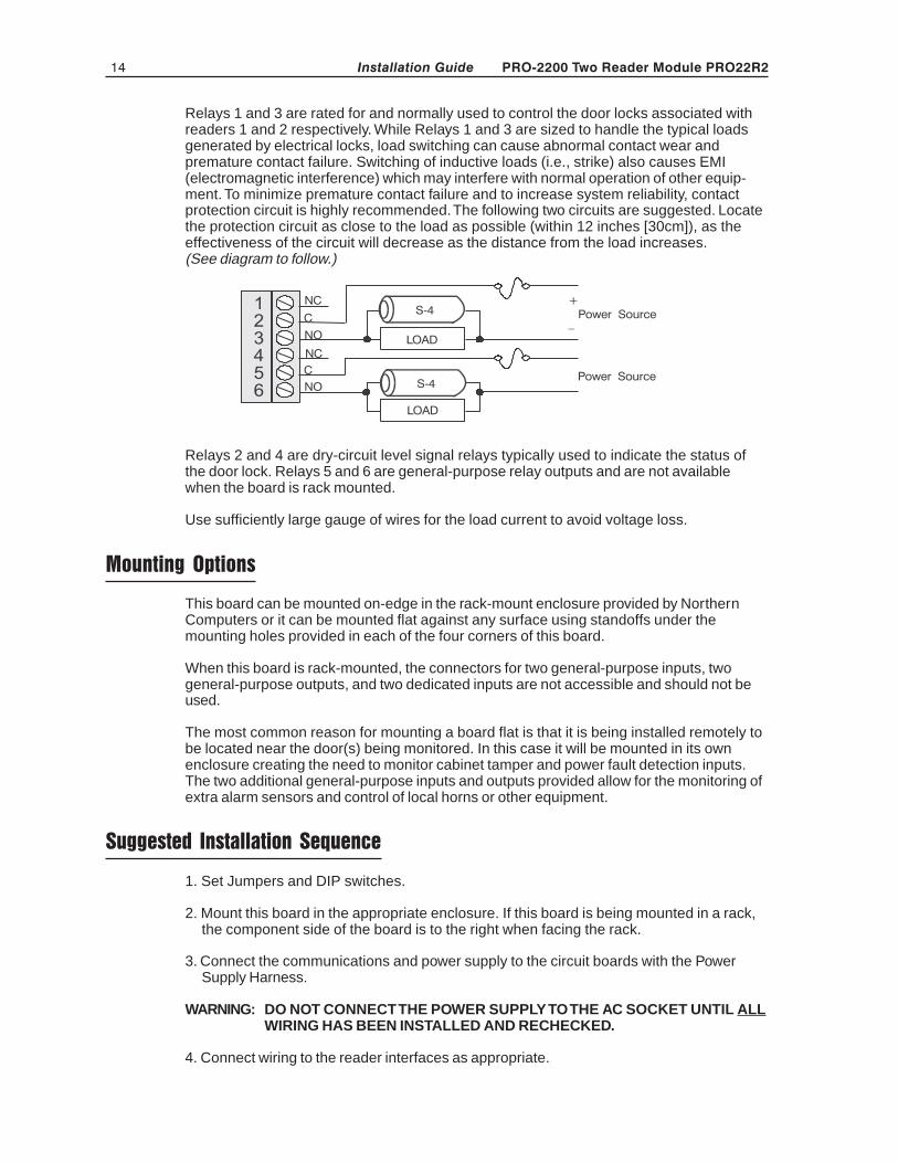
Relays 1 and 3 are rated for and normally used to control the door locks associated withreaders 1 and 2 respectively. While Relays 1 and 3 are sized to handle the typical loadsgenerated by electrical locks, load switching can cause abnormal contact wear andpremature contact failure. Switching of inductive loads (i.e., strike) also causes EMI(electromagnetic interference) which may interfere with normal operation of other equip-ment. To minimize premature contact failure and to increase system reliability, contactprotection circuit is highly recommended. The following two circuits are suggested. Locatethe protection circuit as close to the load as possible (within 12 inches [30cm]), as theeffectiveness of the circuit will decrease as the distance from the load increases.(See diagram to follow.)
Relays 2 and 4 are dry-circuit level signal relays typically used to indicate the status ofthe door lock. Relays 5 and 6 are general-purpose relay outputs and are not availablewhen the board is rack mounted.
Use sufficiently large gauge of wires for the load current to avoid voltage loss.
Mounting Options
This board can be mounted on-edge in the rack-mount enclosure provided by NorthernComputers or it can be mounted flat against any surface using standoffs under themounting holes provided in each of the four corners of this board.
When this board is rack-mounted, the connectors for two general-purpose inputs, twogeneral-purpose outputs, and two dedicated inputs are not accessible and should not beused.
The most common reason for mounting a board flat is that it is being installed remotely tobe located near the door(s) being monitored. In this case it will be mounted in its ownenclosure creating the need to monitor cabinet tamper and power fault detection inputs.The two additional general-purpose inputs and outputs provided allow for the monitoring ofextra alarm sensors and control of local horns or other equipment.
Suggested Installation Sequence
1. Set Jumpers and DIP switches.
2. Mount this board in the appropriate enclosure. If this board is being mounted in a rack,the component side of the board is to the right when facing the rack.
3. Connect the communications and power supply to the circuit boards with the PowerSupply Harness.
WARNING: DO NOT CONNECT THE POWER SUPPLY TO THE AC SOCKET UNTIL ALLWIRING HAS BEEN INSTALLED AND RECHECKED.
4. Connect wiring to the reader interfaces as appropriate.

PRO-2200 Two Reader Module PRO22R2 15Installation Guide
5. Connect wiring to alarm input sensors or install jumper wire as appropriate.
6. Connect relay output wiring as appropriate.
7. Connect communications wiring to the Intelligent Controller.
8. Recheck wiring for correct connections and continuity.
9. When all boards have been installed, connect the Power Supply Cord for properconnections and power.
10. Setup the panel controls using the host software.
Specification
The Two Reader is for use in low voltage, class 2 circuits only.
Primary power: 12VDC±10% 400mA
Relay contacts:Relays 1 & 3 outputs, Form-C, 5A @ 28 VDC, resistiveRelays 2 & 4 & 5 & 6 outputs, Form-C, 2A @ 28 VDC, resistive
Inputs:8 supervised, End of Line resistors 1k ohm ± 1% tolerance2 unsupervised dedicated inputs
Reader interfaceReader power 5 VDC (5 - 6.2) or 12 VDC (pass-through) 150mA max. eachReader LED output TTL compatible, high > 3V, low < 0.5V, 5mA
source/sink max.Reader buzzer output Open collector, 5 VDC open circuit max. 10mA sink max.Reader data inputs TTL compatible inputs
Communication:RS-485 9,600 to 38,400 bps
Wire requirements:Power 1 twisted pair, 18AWGRS-485: 24AWG, 4,000 feet (1,200m) max., 2-twisted pair with shield (120Ω,
23pf) (Belden 9842 or equivalent.)Alarm inputs 1 twisted pair per input, 30 ohms max.Outputs As required for the loadReaders 6 conductors, 18AWG, 500 feet (150m) max. shield and drain
Mechanical:Dimension 5.5" (140mm) W x 9" (229mm) L x 1" (25mm) H
Weight 12 oz. (340g) nominal
Environment:Temperature 0°C to +49°C, operating, –55°C to +85°C, storageHumidity 0% to 85% RHNC
16 PRO-2200 Two Reader Module PRO22R2Installation Guide
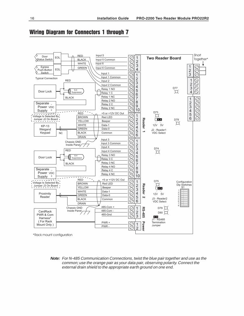
Wiring Diagram for Connectors 1 through 7
Note: For N-485 Communication Connections, twist the blue pair together and use as thecommon; use the orange pair as your data pair, observing polarity. Connect theexternal drain shield to the appropriate earth ground on one end.
1234
12
Two Reader Board
Read
er
1R
ead
er
2
Input 5 Common
Input 5RED
BLACK
DoorStatus Switch
Relay 1 C
GREEN Input 6 CommonEgressPush-Button
Switch
WHITE Input 6
Input 1
Input 1 Common
Input 2
Relay 1 NOS-4SuppressorDoor Lock
BLACK
RED
DRAIN
RED +5 or +12V DC Out
YELLOW Beeper
BROWN Red LED
BLACK Common
GREEN Data-0
NC
KP-13WeigandKeypad
SeparatePowerSupply
-VDC
+
Input 2 Common
Relay 1 NC
Relay 2 NO
Relay 2 C
Relay 2 NC
123456
10
123456789
WHITE Data-1
Chassis GNDInside Panel
123456
10
123456789
Input 3
Input 3 Common
Input 4
Input 4 Common
Relay 3 C
Relay 3 NO
Relay 3 NC
Relay 4 NO
Relay 4 C
Relay 4 NC
DRAIN
RED +5 or +12V DC Out
YELLOW Beeper
BROWN Red LED
BLACK Common
GREEN Data-0ProximityReader
WHITE Data-1
Chassis GNDInside Panel
Voltage Is Selected ByJumper J2 On Board
S-4SuppressorDoor Lock
BLACK
RED
SeparatePowerSupply
–VDC
+
EOL
EOL
123
485-Com +
485-Com -
485-GndCardRack
PWR & ComHarness*( For Rack
Mount Only )
RS
-485
Po
wer
D73
D75
D74
J1 - RS485TerminationJumper
D79
D80
12345678
S1
123456
123
1234
D77
D78
12V 5V
12V 5V
ConfigurationDip Switches
J3 - Reader2VDC Select
J2 - Reader1VDC Select
Voltage Is Selected ByJumper J3 On Board
PWR +
PWR -
Typical Connection
ShortTogether*
*Rack mount configuration
PRO-2200 Two Reader Module PRO22R2 17Installation Guide
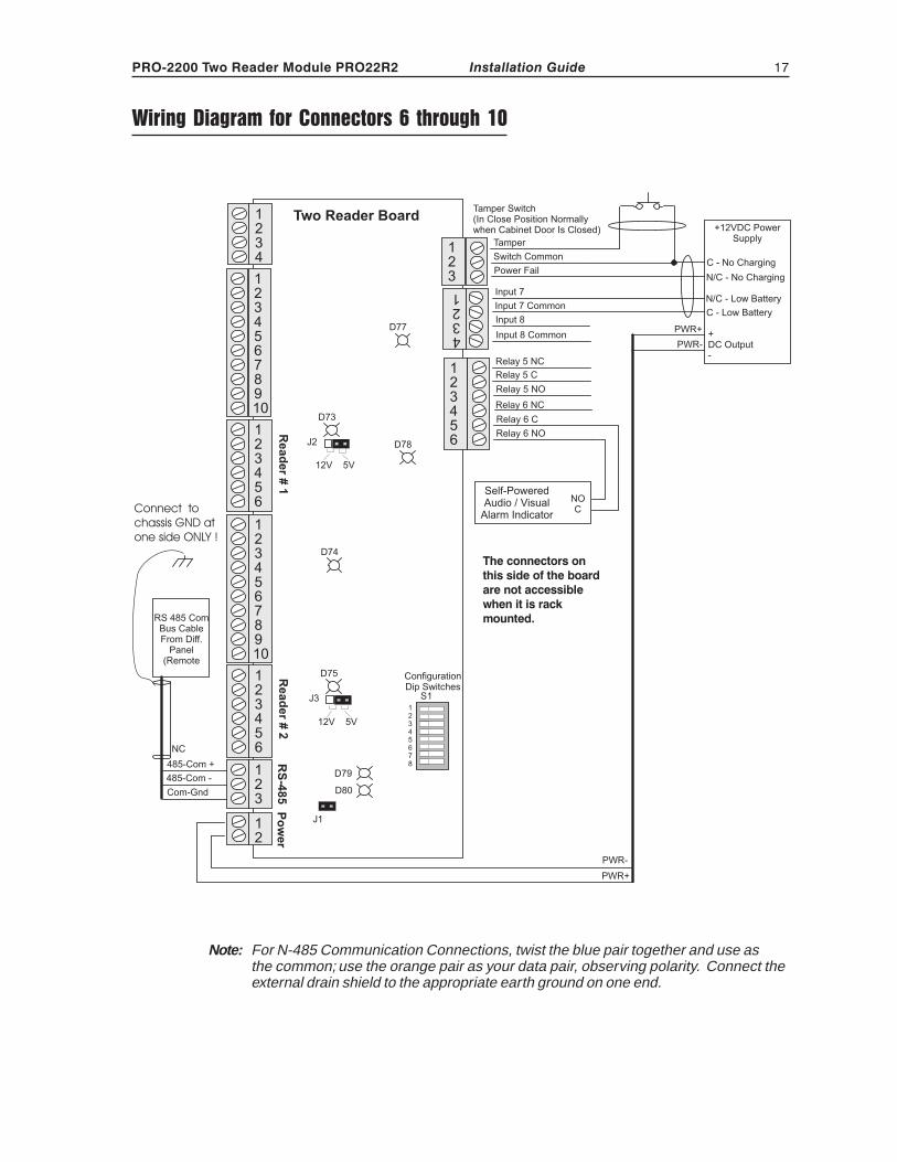
Wiring Diagram for Connectors 6 through 10
Note: For N-485 Communication Connections, twist the blue pair together and use asthe common; use the orange pair as your data pair, observing polarity. Connect theexternal drain shield to the appropriate earth ground on one end.

18 PRO-2200 Two Reader Module PRO22R2Installation Guide
NOTES


Honeywell Security & Data Collection2700 Blankenbaker Pkwy, Suite 150
Louisville, KY 40299(800) 675-3364
www.honeywellaccess.com