proactive well control practices avert dangers
TRANSCRIPT
WHEN IT COMES to well control,being proactive results in safer opera-tions and being fully prepared in theevent a well control situation does occur.This includes utilizing tools such as wellcontrol management systems, well mod-eling software and training.
Alert Disaster Control and its affiliatecompany, John Wright Company(JWC), provide a well control manage-ment system with proprietary technolo-gy and software. This approach com-bines the well engineering expertise andexperience of JWC with Alert’s practicalwell control operations and knowledgeinto a management system that identi-fies potential hazards before a well isspud.
E V E N T L E V E L S
The company considers three levels ofwell control situations, according toMike Allcorn, Managing Director forAlert Disaster Control. The first is anevent that a drilling crew can normallyhandle themselves. Second is an eventthat requires additional externalresources that are not necessarily out-side the norm. The third level is a situa-tion that requires specialized well con-trol support.
The company’s proprietary softwareassociated with the well control man-agement system provides guidance forpersonnel on how to respond effectivelyto an incident for each of the three lev-els. The guidance has been expandedsignificantly through the company’straining experience from traditionalwell control schools, advanced well con-trol programs, workshops and examin-ing case histories.
T R A I N I N G
Once the management system is inplace, specific training is provided todrilling personnel, both line and man-agement. The primary customer is theoperator. The actual interface in anevent would be with the operator’s man-agement team that encompasses itsshore-based management and engineer-ing group. It would also include thedrilling facility’s offshore installationmanager (OIM) and the contractor’sdrilling superintendent and drillingcrews.
Primary training by the company con-sists of internationally accredited stan-dards set by IADC through the WellCAPprogram or the International Well Con-trol Forum as well as specific well con-trol schools for drillers and supervisorsfor both onshore and offshore locations.Training includes actual well controlexercises. The latter is important due tothe varying amount and type of supportequipment and resources available invarious areas.
The well control management systemprovides training specific to the dutiesand responsibilities of the individualand his position. For example, the drillerwould not necessarily be provided thesame well control training as an OIM.
“However, there is a strong focus on theteam element as far as bringing the indi-viduals and their skills together toresult in a unified approach so as to mit-
igate the results of any of the threeevent levels as quickly and effectively aspossible,” Mr Allcorn said.
Training is also based on the company’swell modeling software that is used todevelop blowout contingency plans aspart of the overall well control manage-ment system. Worst case scenarios canbe modeled for a particular well prior tothe well being spud. The modeled situa-tion can be set up with advanced simu-lators where personnel can be runthrough a series of scenarios and drills,providing them with the understandingof the situation and guidance on how tocontrol a situation prior to drilling thewell.
Training is provided by the company ina classroom setting as well as on its fullsize rig floor simulators located in Sin-gapore and Dubai. Mobile training pack-ages also can be used on site at the cus-tomer’s onshore or offshore locations.
“What we have been able to do with ourmodeling capability is to develop amodel of potential scenarios for a par-ticular well,” Mr Allcorn explained. “Inaddition to the traditional well controlschool, we can add a 2-3 day advancedworkshop where we set up the simula-tors to run through scenarios of the spe-cific well to be drilled.”
The simulators can provide training forspecific potential events and how theymay be handled, for example, identify-ing lost circulation zones and then plan-ning how to react to plug and seal thatzone.
Planning for a project could take monthsor only days, depending on the complex-ity. For example, the company recentlycompleted a project on Sakhalin Islandin which it was involved for about sixmonths prior to mobilization of thedrilling rig. This particular serviceincluded assessment of the drilling rigfrom a well control standpoint, develop-ment of a management system, siteassessment as to the availability of localresources and development of a plan toassist the customer in the event of aworst case well control event.
S O F T W A R E
Alert’s proprietary software ties every-
48 D R I L L I N G C O N T R A C T O R September/October 2004
Proactive well control practices avert dangers
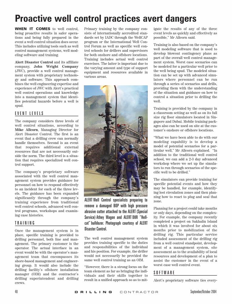
ALERT Well Control specialists preparing toremove a damaged BOP with high pressureabrasive cutter attached to the ALERT (SpecialService) Athey Wagon and ALERT D8R “Hell-cat” bulldozer. Photograph courtesy of ALERTDisaster Control.

thing together, Mr Allcorn noted. It takeselements of the well control manage-ment system, data obtained through themodeling process and combines tradi-tional training methods plus simulatorsto provide personnel with the knowledgeof what is potentially going to take placedownhole and what must be done on thesurface to control an incident.
The company’s database provides wellinformation that can be drawn upon todevelop various well control scenarios.Additionally, information from a cus-tomer’s actual well control event can beplugged into the software and simulatorto help resolve the situation. The cus-tomer would provide the company withdata obtained from the well such aspressures, temperatures, etc. Alert willuse case histories of similar events tohelp resolve the current well control sit-uation.
“Preferably, all of the information isobtained before the well is spud in orderto look at potential situations,” Mr All-corn said. “The data can be provided by
the operator from offset wells in thearea and the potential situations arebased upon our historical data and mod-eling knowledge.”
R E S O U R C E S
A critical element of the well controlmanagement system is having theresources and equipment in place,either locally or in relatively close prox-imity to the wellsite, should they becomenecessary. The company conducts awellsite assessment and meets with var-ious service companies in the region aswell as national authorities. The focus ison particular requirements to mobilizeequipment and specialized personnelinto a country in the event of a well con-trol situation.
This assessment includes identifyingperformance capabilities of local servicecompanies, and paperwork and proce-dures to bring equipment into a country.
“Those elements provide a very clearpicture of what resources are available
and if they are available within theimmediate location,” Mr Allcornexplained. “We will also know how far
September/October 2004 D R I L L I N G C O N T R A C T O R 49
ALERT Well Control specialists cutting rig sub-structure and debris with a thermal lance toclear and access the well area. Photographcourtesy of ALERT Disaster Control.

away the equipment is and what wouldbe required to bring that equipment intothe region, whether it’s pre-contractswith heavy-lift companies, shippingcompanies or other transportation com-panies.”
Alert has alliances with several equip-ment companies in addition to its ownequipment strategically placed aroundthe world.
C A S E H I S T O R I E S
Gulf of Mexico. An errant shrimp boatstruck a single caisson oil well in theGulf of Mexico, bending the well to theseabed in 24 ft of water. When the wellwas pulled back vertical, all casingstrings were observed cracked justbelow the mudline. The tubing wasapparently intact and the SCSSSV washolding.
The remedial strategy was to drive a 60-in. caisson around the well, jet the mudout below the cracks, tie-back the dam-aged casing strings and tubing with newones and bullhead the well dead.
If anything went wrong with the opera-tion, however, oil could potentially flowuncontrolled into the Gulf for over amonth while a relief well was beingdrilled. This risk was unacceptable.
JWC was called to evaluate mitigationsolutions using relief well technology.Several options were considered. Onewas to drill to the perforations andstand by while the surface operationswere performed. The perforations weregravel packed. Milling operations mightdislodge the production packer.
The chosen plan was to intersect theproblem well just above this packer, cuta notch in the 7 5/8-in. casing withoutcutting the tubing and circulate mudfrom the relief well back to the surfacethrough the problem well. With thataccomplished, a retainer could be setand a short cement plug placed in theannulus above the production packer.
This would prevent the packer frombecoming dislodged if the tubing neededto be cut. The relief well would thenstandby until the surface remediationwas complete.
The relief well was implemented asplanned. A notch was cut at 9,600 ftusing a custom mill on a motor. Therelief well U-tubed into the problem wellannulus, a short cement plug was placedand the relief well stood by to cut thetubing if a problem occurred during thesurface remediation.
Relief Well Used to Safeguard a Pro-duction Platform. Problems beganwhen a sidetracked well broached undera gas platform while attempting to cir-culate a kick. The well flowed gas andwater uncontrolled around the conduc-tors to the seabed. The flow lasted forapproximately 10 hours before the openhole collapsed around the drillpipe. Thegas did not ignite and there was noapparent major surface or structuraldamage to the rig or 12-slot platform.
JWC responded with a three-man engi-neering team to assist with control oper-ations. Wireline logs showed the well tobe crossflowing below the bridge. Flowdiagnostics using Olga-Well-Kill helped
50 D R I L L I N G C O N T R A C T O R September/October 2004

the operator make quick decisions onthe path forward. The well was subse-quently plugged above the crossflow anda replacement pressure relief well wascompleted. There was less risk to theplatform to deplete the gas than to riskescalation during a control attempt.
While attempting to bring a well adja-cent to the blowout back on stream, itwas discovered that all tubulars wereflow-cut just below the mudline. TheSCSSSV was the only barrier betweenthe platform and another blowout.
The risk was too high to attempt reme-dial operations from the surface, as theplatform could be destroyed before arelief well could be drilled. Another lessrisky method was needed. JWC wasagain commissioned to propose reliefwell intervention methods to safeguardthe platform with minimal escalationrisk.
Three options were proposed. The basicdesign strategy was to drill an interven-tion well from an adjacent bridge-con-
nected platform and intersect the prob-lem well at its production casing stringboth above and below the producingreservoir perforations. After intersec-tion was confirmed using homing-intechnology, a liner would be set in therelief well. With this accomplished, thelower intersection zone would be perfo-rated through both strings using orient-ed tubing conveyed perforating guns.
Once adequate hydraulic communica-tion was confirmed, the upper intersec-tion zone would be perforated using thesame technique.
A re-settable test packer would then berun to confirm circulation between thelower and upper perforations throughthe problem well’s production casing.When this was confirmed, a cementretainer would be set just above thelower intersection.
Cement would then be circulated downthe relief well work string, through theretainer, up the problem well’s produc-tion casing and back into the relief
well’s annulus. With this accomplishedthe relief well would circulate out excesscement from its annulus (confirmingcement circulation through the problemwell).
This would plug the tubing, perforationsand production casing annulus withcement between the lower and upperintersection depths.
As a final assurance, a balanced cementplug would be set across the upper per-forations and squeezed into the problemwell’s tubing designed to lift above theproduction packer. With the interven-tion completed, the well would be turnedinto a producer replacing the problemwell.
JWC managed the implementation of thespecial operations for this well with afour-man engineering team. The opera-tions were completed within the budget-ed time frame. Diagnostics indicated thewell was plugged as designed and theproject objectives met. n
September/October 2004 D R I L L I N G C O N T R A C T O R 51