proceedings of the 2nd gi/itg kuvs fachgespräch inter-vehicle
TRANSCRIPT
Proceedings of the 2nd GI/ITG KuVS Fachgespräch Inter-Vehicle Communication (FG-IVC 2014)
Raphael Frank, University of Luxembourg
Markus Forster, University of Luxembourg
Christoph Sommer, University of Innsbruck
Frank Kargl, Ulm University
Thomas Engel, University of Luxembourg
Luxembourg, February 2014
Technical Report: TR-SnT-2014-4 ISBN: 978-2-87971-124-9
Tho
mas
Please cite as:
R. Frank, M. Forster, C. Sommer, F. Kargl, T. Engel, “Proceedings of the 2nd GI/ITG KuVS Fachgespräch Inter-Vehicle Communication (FG-IVC 2014)“, University of Luxembourg, Interdisciplinary Centre for Security, Reliability and Trust (SnT), TR-SnT-2014-4, ISBN 978-2-87971-124-9, February 2014.

Proceedings of the 2nd GI/ITG KuVS Fachgespräch Inter-Vehicle Communication
(FG-IVC 2014)
February 20-21, 2014, Luxembourg City, Luxembourg
Preface GI/ITG KuVS Fachgespräch was organized on the topic of inter-vehicular
communication. Discussions revolved around both the state of the art and around future directions of inter-vehicle communication research, from physical layer optimizations to novel applications of vehicular networks and from microscopic evaluation metrics to problems of scale, crime, and privacy. The goal of this new Fachgespräch was again to bring together talented young researchers to follow-up on the discussions.
Over the last few years, significant efforts are being carried out by industry, academia and government agencies to improve driving safety, increase vehicle traffic efficiency and decrease fuel consumption by exploiting vehicular communications and networking technologies. These technologies, which are generally referred to as VANET (Vehicular Ad Hoc Networks), include Vehicle-to-Infrastructure (V2I), Vehicle-to-Vehicle (V2V) communications and can be based on short- and medium-range communications as well as on cellular systems.
In February 2013 the first edition of the GI/ITG KuVS Fachgespräch was held in Innsbruck, Austria. Due to its success, the Fachgespräch was reorganized in February 2014, this time in Luxembourg City, Luxembourg. With more than 25 participants, the event was well attended. Young researchers have presented twelve papers on different topics around IVC. Every presentation was followed by a discussion leading to a dynamic interaction between the participants. In addition to an academic keynote held by Prof. Claudio Casetti, a VEINS tutorial has been organized.
February 2014
Raphael Frank Markus Forster
Christoph Sommer Frank Kargl
Thomas Engel
1


Contents ���
R. Frank, M. Forster, C. Sommer, F. Kargl, T. Engel: Preface ..................................... 1
M. Forster, R. Frank, T. Engel: DRIVE: An evaluation in a Closed Border Environment ................................................................................................................... 5
C. Buettner, S. A. Huss: Anonymous Credentials and Attribute-Based Authorization Tickets in Car-to-X Communication ............................................................................. 9
E. Masalkina, D. Eckhoff, R. Berndt, R. German: Towards the City-scale Simulation and Performance Assessment of Electric Vehicles ...................................................... 13
T. Gehrsitz, W. Kellerer, H. Kellermann: In-car communication based on power line networks ....................................................................................................................... 17
M. Feiri, J. Petit, F. Kargl: An evaluation framework for pre-distribution strategies of certificates in VANETs ................................................................................................ 21
R. W. van der Heijden, F. Kargl: Open issues in differentiating misbehavior and anomalies for VANETs ................................................................................................ 23
C. Ide, K. Piontek, C. Wietfeld: Identifying LTE Connectivity Hot Spots in Vehicular Environments: A Learning Approach .......................................................................... 26
M. Feiri, J. Petit, F. Kargl: Real World Privacy Expectations in VANETs ................ 29
R. Riebl, C. Facchi: Implementation of Day One ITS-G5 Systems for Testing Purposes ....................................................................................................................... 32
M. Segata, F. Dressler, R. Lo Cigno: A Modular Approach to Platooning Maneuvers...................................................................................................................................... 36
J. Timpner, S. Rottmann, L. Wolf: Vehicular Communications in the V-Charge Project .......................................................................................................................... 40
L. Codeca, R. Frank, T. Engel: Improving Traffic in Urban Environments ................ 44


DRIVE: An evaluation in a Closed BorderEnvironment
Markus Forster, Raphael Frank, Thomas EngelInterdisciplinary Centre for Security, Reliability and Trust
University of Luxembourg, 1359, Luxembourg{markus.forster|raphael.frank|thomas.engel}@uni.lu
Abstract—In this short paper we address the problem ofabrupt breakdowns in traffic flow as a consequence of high trafficdemand in combination with small driver inaccuracies. Firstwe provide a brief overview on a Cooperative Advanced DriverAssistance System (CADAS) called Density Redistribution throughIntelligent Velocity Estimation (DRIVE) that has been proposedto mitigate jam formations. Next, we perform an analysis on thetraffic dynamics in a close border environment that enables usto run simulations with well defined vehicular densities.
Keywords— Traffic Modeling, Vehicular Networks, CongestedFlow, Shock Waves
I. INTRODUCTION
Traffic demand has significantly increased over recentdecades. The traditional solution to face this problem hasbeen the extension of the road network by constructing newroads or adding lanes to already existing ones. This strategyhowever has come to a point where in most areas physicalroad extensions are no longer possible [1]. As a possibleremedy, one should also consider the fact that, due to currentcompletely uncoordinated vehicular traffic, the already avail-able capacity is not fully exploited. Simulations and empiricalanalysis have shown that vehicular traffic is in free flow onlyfor relatively low densities when interactions between vehiclesare negligible [2].
To improve the current situation it is necessary to relyon Advanced Driver Assistance Systems (ADAS) systems thatequip vehicles with several sensors, enabling them to recognizetheir surroundings and to notify motorists to take correctiveactions or, in some cases, to implement such corrections auto-matically. An example of such a system is the Adaptive CruiseControl (ACC) that can maintain minimum safety headway tothe vehicle ahead. Such systems can react much faster thana human driver to sudden downstream vehicle maneuvers andtherefore allow to use smaller safety distances [3].
It has been until recently that researchers consider the flowdynamics to increase the efficiency of Cooperative AdaptiveCruise Control (CACC). In [4], the authors propose a strategyto stabilize traffic flow by periodically beaconing relevanttraffic information to close-by vehicles. Vehicles that detectperturbations downstream try to keep a larger gap to theirpredecessor in order to compensate traffic inhomogeneity. Theyshow that at an equipment rate of 30% free flow can be restoredeven at high traffic densities. An improvement of this work hasbeen proposed by the same authors in [5], where the modelincludes the effect of the human reaction time, confirming theprevious findings.
In this paper we perform an analysis of a previous spec-
ified network protocol used within a Cooperative AdvancedDriver Assistance System (CADAS) that connects vehiclesvia anVehicular Ad Hoc Network (VANET) and lets themexchange recent and relevant traffic information.
The proposed DRIVE protocol [6] broadcasts with an eventdriven messaging scheme critical information such as positionand velocity. This information can be used by following vehi-cles far behind to learn about the traffic situation downstream.This information is collected and evaluated in a way thatprovides a consistent picture of the traffic situation ahead.By using the Lighthill-Whitham-Richard model (LWR) [7],[8], it is possible to estimate a density gradient betweentwo communicating vehicles and use this information forvelocity estimations. The aim of this protocol is to redistributeoncoming vehicles in a way that prevents congestion shockwaves from forming. We show that, by giving individual ve-locity recommendations, even with a low number of equippedvehicles one can achieve significant improvements in overalltraffic flow and average travel times. Since this does not leadto a reduction in safety distance, full system coverage is notrequired to ensure collision-free driving.
II. PROTOCOL DESCRIPTION
The aim of the presented protocol is to improve vehicularflow in situations of high traffic demand without requiringexcessive network resources. Furthermore, the protocol shouldimprove the overall traffic flow even with low equipment rates.The flow improvement is achieved by the use of Density Redis-tribution through Intelligent Velocity Redistribution (DRIVE).For a full description of the protocol please refer to the originalpaper [6].
In the next subsection we provide an overview of themessaging mechanism of DRIVE. In the next but one subsec-tion we provide a brief insight of the recommended velocityestimation. Finally we demonstrate the execution of DRIVEwith an example.
A. Message propagation
The network protocol, used for communication ofDRIVE messages is fully compliant with the IEEE 802.11pstandard for Wireless Access in Vehicular Environments(WAVE) [9], [10].
For our analysis, we assume channel characteristics aslisted in Table I. The protocol is divided into three main parts.First part is the Message Dissemination, second part is theMessage Reception and the third part describes the Message
5

Forwarding. A complete description of those three phases isgiven in the next subsections.
TABLE I: Properties of radio channel
PHY 802.11pFrequency 5.9 HzMaximum Sending Power 20 mWThermal Noise −110 dBmSensitivity −89 dBmSignal Attenuation Threshold −89 dBmMAC 1609_4Transmission Power 20 mWBitrate 18 MbpsService Channel 2
1) Message Dissemination: DRIVE is an event drivenprotocol, meaning that messages are only disseminated whena certain event occurs. This implies that the WAVE beaconingis not used in our analysis.
The event to trigger the dissemination of a DRIVE notifi-cation is a significant slowdown or a unusually low velocity. Aslowdown is considered to be significant if the actual velocityis 10 km/h lower than the velocity one second ago. Due to thefact, that our protocol has been designed for highway scenariosvelocities lower than 50 km/h are considered as low velocities.
When detecting a slowdown event, an equipped vehiclebroadcasts a notification message containing the information:
mh = [id, x, y, t, v, TTL] (1)
where h ∈ H is a unique message identifier and id is aunique identification of the originating vehicle. x and y arethe GPS-coordinates of the originator. The remaining valuesare the timestamp of the originator at message creation (t), theactual velocity of the originator at message creation (v) and apreselected Time To Life (TTL).
2) Message Reception: The protocol will only check everysecond if a relevant notification has been received. This impliesthat messages arriving within this time interval ∆Tm have tobe precomputed and stored for further handling.
Vehicles receiving a message mj as given by the messageSpecification 1 have to check first if this message is relevantfor them. This means, if no message has been received before,within the current time interval the actual message will bestored in a temporary variable mact. In case of the presenceof an older message the algorithm first has to find out ifthe new message is more recent than the already storedone. This is done by comparing the spatial distances of themessage originators to the receiver. This means that a vehicle i,receiving a message mj will consider this message more recentthan message a mact if the spacial distance between vehicle iand j is less than that between i and the vehicle originatingmessage mact, both vehicles are driving in the same directionand vehicle j is ahead of vehicle i.
3) Message Forwarding: Each message received by a ve-hicle with opposite driving direction will be rebroadcast if themessage has not been received before or the TTL is equal zero.This is done to increase the sending range by using oppositelane vehicles as relays.
In case of equal driving directions between sender jand receiver i the message will only be rebroadcast if it isconsidered recent (cf. Message Reception phase).
vj(1) = 25 m/svi(1) = 35 m/svi,safe(1) = 29 m/s
d∗i,j = 290 m cτ = 210 m
c ≈ 15 km/h
Fig. 1: DRIVE Example
The message forwarding ends if the maximum propagationradius is reached. Since patterns of a wave are recurrent,the maximum message propagation distance has been setto the maximum wavelength of a shock wave, in our case2000 m [11].
B. Computation of Optimal Velocity
We assume that a driver always tries to drive as fast asallowed by the traffic rules. Furthermore, we assume that theonly cause of a slow down is an increasing density the trafficflow ahead. Then, having the information of the next known
0 20 40 60 80 100 120
density ρ [
1km
]0
500
1000
1500
2000flow
q [ 1 h
]
Fig. 2: Triangular fundamental diagram
vehicle in front, we estimate the unknown traffic situationbetween the receiving vehicle i and the sending vehicle j byapplying the LWR model with the solution for the TransportEquation:
c =Qj −Qi
ρj − ρi(2)
where Qj and Qi are the calculated traffic flows for vehicle jand i, respectively. ρj and ρi denote the vehicular densities cor-responding to the actual velocities. Based on this information,it is possible to estimate the traffic conditions between vehiclesi and j. Obviously, only situations where the density at thesender position ρj is greater than at receivers position ρi areof interest. Next, we can compute a velocity recommendationvi,safe:
vi,safe = vj +d∗i,j − vjT
τ(3)
d∗i,j = di,j + cτ (4)
τ =di,j
∆vi,j(5)
with di,j being the distance between vehicles j and i, ∆vi,jbeing the velocity difference between vehicles i and j and τbeing the time for vehicle i to reach vehicle j with the given
6

0 10 20 30 40 50 60Density ρ in veh/km
20
40
60
80
100
120
140
Average velocity v in km/h
0 percent10 percent50 percent100 percent
(a) Velocity density diagram
10 20 30 40 50Density ρ in veh/km
0
1
2
3
4
5
Average Message Hop Count
10 percent50 percent100 percent
(b) Average hop-count
10 20 30 40 50Density ρ in veh/km
0
1
2
3
4
5
6
7
8
Average number of sent messages per vehicle per second
10 percent50 percent100 percent
(c) Average number of sent messages
Fig. 3: Simulation results
velocity difference. vi,safe ensures that vehicle i will adapt itsvelocity in a way not to hit the tail end of the shock waveproduced by vehicle j within the time τ . For more informationwe refer the reader to [6].
C. DRIVE Example
An example of the DRIVE protocol is given in Figure 1.Suppose, vehicle j experiences a slowdown from vj(0) =35 m/s to vj(1) = 25 m/s. The onboard DRIVE equip-ment broadcasts a message mh(j) = [id, xj , yj , t, vj , TTL]according to the message given in Definition 1. A vehiclei, receiving mh(j) and considering it as most recent eventnotification, first checks if vj(1) < vi(1). If this holds true, thedensities ρj and ρi at position xj and xi are estimated. Havingan estimate of the densities and the measured values of thevelocities of both vehicles we can easily compute the densitygradient between them. In the given example and based on thetriangular fundamental diagram as given in Figure 2 this leadsto an approximated shock wave traveling with c = −15 km/hagainst traffic direction.
Knowing this, from Equations 3, 4 and 5 DRIVE computesa safe velocity for vehicle i given by vi,safe(1) = 29 m/s inorder to avoid reaching the tail end of the shock wave producedby vehicle j within the time τ as given by Equation 5, andthus reducing the risk of a traffic perturbation.
III. PROTOCOL EVALUATION
In this section we describe the simulation setup and discussthe obtained results.
Simulation Setup
All simulations presented in this paper have been per-formed using the Veins framework [12]. Veins offers aconnection link between the two well-established simulatorsOmnet++ [13] and SUMO [14]. With this setup we havea bi-coupled network, meaning that the mobility simulationinteracts with the network simulation and vice versa.
The general simulation setup is an octagonal one laneclosed loop with an overall length of 10 km. A given numberof vehicles are driving around this loop counter clockwise for2 hours. The mobility scenario is crash-free and specifies thatevery driver tries to increase his speed up to the maximum
allowed velocity vmax = 130 km/h. Previous studies haveshown that after exceeding a certain density, the inefficiency ofhuman driving will lead to slow downs [7], [8]. To reproducethis behavior with the Intelligent Driver Model (IDM) [15]used for our simulations, it is necessary to introduce a smallprobabilistic factor. In our scenario this probability is set toPd = 1% meaning that a driver will reduce its current speedby 1 m/s for 1 s with the given probability. Several simulationruns have been performed with different vehicular densitiesand different equipment rates. The aim is on the one handto show how DRIVE optimizes traffic flow and on the otherhand to provide an insight of the network characteristics of theprotocol.
The simulated densities ρ are given by the set R ={1, 2, 4, 6, 8, 10, 12, 14, 16, 18, 20, 30, 40, 50, 60} vehicles perkm per lane. To provide a detailed overview on the DRIVEprotocol, four equipment rates, ranging from uncoordinated(0%) over 10% and 50% to full coverage (100%) have beensimulated.
Simulation Results
In this section we discuss the simulation results. Fourdifferent analyses with the above mentioned equipment ratesof the DRIVE system have been performed. The results showthe impact of DRIVE on traffic flow with vehicles that mightbe equipped with a CACC but additionally takes into accountthe effects of human behavior.
Figure 3a shows the average velocity over the given setof densities R with the above mentioned equipment rates. Asexpected, the average velocities are decreasing with increasingdensity. However the DRIVE protocol alleviates this effect byredistributing the vehicles in the system in a way that enablesthem to drive with higher speeds. Between completely unco-ordinated traffic and 100% equipment rate with the DRIVEsystem, the average velocity can be increased by up to 25% inthe critical density region between 15 veh/km and 25 veh/km.
Figure 3b illustrates the average message hop-count. Thismetric indicates how far messages travel backward in the trafficchain or how often they have been forwarded. One can see thatwith increasing density, the message travel distance increasesup to a certain point (40 veh/km). Beyond that density, mostvehicles are within transmission range reducing the message
7
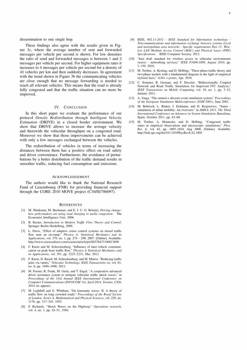
dissemination to one single hop.These findings also agree with the results given in Fig-
ure 3c, where the average number of sent and forwardedmessages per vehicle per second is shown. For low densitiesthe ratio of send and forwarded messages is between 1 and 3messages per vehicle per second. For higher equipment rates itincreases to 8 messages per vehicle per second for a density of40 vehicles per km and then suddenly decreases. In agreementwith the trend shown in Figure 3b the communicating vehiclesare close enough that no message forwarding is needed toreach all relevant vehicles. This means that the road is alreadyfully congested and that the traffic situation can no more beimproved.
IV. CONCLUSION
In this short paper we evaluate the performance of ourprotocol Density Redistribution through Intelligent VelocityEstimation (DRIVE) in a closed border environment. Weshow that DRIVE allows to increase the average velocityand therewith the vehicular throughput on a congested road.Moreover we show that those improvements can be achievedwith only a few messages exchanged between the vehicles.
The redistribution of vehicles in terms of increasing thedistances between them has a positive effect on road safetyand driver convenience. Furthermore, the avoidance of pertur-bations by a better distribution of the traffic demand results insmoother traffic, reducing fuel consumption and emissions.
ACKNOWLEDGEMENT
The authors would like to thank the National ResearchFund of Luxembourg (FNR) for providing financial supportthrough the CORE 2010 MOVE project (C10/IS/786097).
REFERENCES
[1] M. Shinkman, M. Buchanan, and E. I. U. G. Britain), Driving change:how policymakers are using road charging to tackle congestion. TheEconomist Intelligence Unit, 2006.
[2] B. Kerner, Introduction to Modern Traffic Flow Theory and Control.Springer Berlin Heidelberg, 2009.
[3] L. Davis, “Effect of adaptive cruise control systems on mixed trafficflow near an on-ramp,” Physica A: Statistical Mechanics and itsApplications, vol. 379, no. 1, pp. 274 – 290, 2007. [Online]. Available:http://www.sciencedirect.com/science/article/pii/S0378437106013690
[4] F. Knorr and M. Schreckenberg, “Influence of inter-vehicle communi-cation on peak hour traffic flow,” Physica A Statistical Mechanics andits Applications, vol. 391, pp. 2225–2231, Mar. 2012.
[5] F. Knorr, D. Baselt, M. Schreckenberg, and M. Mauve, “Reducing trafficjams via vanets,” Vehicular Technology, IEEE Transactions on, vol. 61,no. 8, pp. 3490–3498, 2012.
[6] M. Forster, R. Frank, M. Gerla, and T. Engel, “A cooperative advanceddriver assistance system to mitigate vehicular traffic shock waves,” inProceedings of the 33rd Annual IEEE International Conference onComputer Communications (INFOCOM’14), April 2014, Toronto, CND,2014 (to appear).
[7] M. Lighthill and G. Whitham, “On kinematic waves. II. A theory oftraffic flow on long crowded roads,” Proceedings of the Royal Societyof London. Series A, Mathematical and Physical Sciences, vol. 229, no.1178, pp. 317–345, 1955.
[8] P. Richards, “Shock Waves on the Highway,” Operations research,vol. 4, no. 1, pp. 42–51, 1956.
[9] IEEE, 802.11-2012 - IEEE Standard for Information technology -Telecommunications and information exchange between systems Localand metropolitan area networks - Specific requirements Part 11: Wire-less LAN Medium Access Control (MAC) and Physical Layer (PHY)Specifications. IEEE Computer Society, 2012.
[10] “Ieee draft standard for wireless access in vehicular environments(wave) - networking services,” IEEE P1609.3/D8, August 2010, pp.1–159, 2010.
[11] M. Treiber, A. Kesting, and D. Helbing, “Three-phase traffic theory andtwo-phase models with a fundamental diagram in the light of empiricalstylized facts,” ArXiv e-prints, Apr. 2010.
[12] C. Sommer, R. German, and F. Dressler, “Bidirectionally CoupledNetwork and Road Traffic Simulation for Improved IVC Analysis,”IEEE Transactions on Mobile Computing, vol. 10, no. 1, pp. 3–15,January 2011.
[13] A. Varga, “The omnet++ discrete event simulation system,” Proceedingsof the European Simulation Multiconference (ESM’2001), June 2001.
[14] M. Behrisch, L. Bieker, J. Erdmann, and D. Krajzewicz, “Sumo -simulation of urban mobility: An overview,” in SIMUL 2011, The ThirdInternational Conference on Advances in System Simulation, Barcelona,Spain, October 2011, pp. 63–68.
[15] M. Treiber, A. Hennecke, and D. Helbing, “Congested trafficstates in empirical observations and microscopic simulations,” Phys.Rev. E, vol. 62, pp. 1805–1824, Aug 2000. [Online]. Available:http://link.aps.org/doi/10.1103/PhysRevE.62.1805
8

Anonymous Credentials and Attribute-BasedAuthorization Tickets in Car-to-X Communication
Carsten BüttnerAdam Opel AG
Advanced TechnologyRüsselsheim, Germany
Sorin A. HussTechnische Universität Darmstadt
Integrated Circuits and Systems LabDarmstadt, Germany
Abstract—In this paper we propose an approach that allowsan ITS vehicle station (IVS) to anonymously authenticate itself atapplications with attribute-based access restrictions. For authen-tication purposes we use attribute-based authorization tickets,which are granted after the IVS proved, that it fulfills all accessrestrictions. For the proof of attributes we rely on anonymouscredentials, which are sets of verified attributes. The resultingsystem supports billing of service usage and revocation of anIVS, tickets, anonymous credentials or single attributes, whileprotecting the privacy of the IVS.
I. INTRODUCTION
In safety relevant communication over ETSI ITS-G5A [1]an ITS Vehicle Station (IVS) authenticates itself by signingall messages with the help of an Authorization Ticket (AT).Besides these safety applications the IVS can also use non-safety applications over ETSI ITS-G5B or cellular commu-nication. To authenticate this kind of communication it is notsufficient to sign all messages with the help of an AT for safetyapplications, as some applications will have access restrictions.A possible restriction could be for example, that the IVS is of aspecific brand or certain sensors or features have to be present.Some Service Providers (SP) might also want to bill the IVSfor usage of their application.
In this paper we propose a system that relies on anonymouscredentials to issue attribute-based authorization tickets. Eachticket can only be used for specific applications. An IVScan take these tickets to anonymously authenticate itself atapplications with access restriction. If the application requiresbilling, the IVS may pay with anonymous digital money. Inaddition our system supports the revocation of an IVS, tickets,anonymous credentials, or single attributes. We thus protect theprivacy of the IVS to the SP as well as to the other entities.
The rest of this paper is organized as follows: In Sec-tion II we discuss anonymous credentials. The entities usedin our system are described in Section III. Previous work inauthenticating an IVS in Car-to-X communication is reviewedin Section IV. We introduce the new system with attribute-based authorization tickets in V. In Section VI we discuss thedifferent kinds of possible revocation supported in our system.Finally, we conclude in Section VII.
II. ANONYMOUS CREDENTIALS
In an anonymous credential system, introduced byChaum [2], an issuer provides credentials to users, whereas
a credential denotes a set of attributes certified by the issuer.An attribute consists of a key (e.g., brand) and a value (e.g.,Opel). With this credential the user can prove to a verifier thathe or she possesses certain attributes certified in the credential.To convince the verifier, she derives a token that only containsthe subset of attributes she wants to prove. So, the verifierlearns only the necessary attributes of the user. A user canalso prove that the content of a ciphertext produced for a thirdparty is the value of a certain attribute without revealing theattribute to the verifier. Several proofs of the same attributescannot be linked, because each time another token is beingderived. It is possible to prove predicates like or, and, greaterthan, smaller than and equals over the attributes.
Possible attributes for an IVS are brand or production dateand features like traffic sign recognition, electric engine orBluetooth.
As an example, Equation 1 shows how it is possible tocheck if an IVS is manufactured by GM, without leaking thebrand of the IVS. This is realized by checking for all GMbrands, if the attribute brand equals to the name of the brand.The derived token then indicates, if the equation is true or falseand so reveals only the manufacturer and not the brand to theverifier.
brand = ”Opel”∨ brand = ”Chevrolet”∨ brand = ... (1)
Equation 2 can be used to prove that an IVS is not olderthan x days. From the result a verifier learns, that the IVS ismanufactured less than x days ago but not the exact date.
production_date > today − x (2)
III. ENTITIES
We use the following entities in our system to obtainattribute-based certificates:
Root CA: The Root Certification Authority (CA) is thetrust anchor of the system. It certifies the Enrolment andAuthorization Authorities. Every IVS in the system has to trustthe Root CA in order to trust the other entities.
IVS Enrolment Authority: The IVS Enrolment Authority(IVS EA) issues the Enrolment Certificate (EC) and credentialto the IVS. In order to issue credentials, the IVS EA has adatabase with all attributes of all ITS Vehicle Stations it isresponsible for.
9
Root CA
IVS AuthorizationAuthority
IVS
(IV.A2)
(IV.B2)
(IV.B4)
(IV.B1)
(IV.B5)
(IV.B3)
IVS EnrolmentAuthority
(IV.A1)
IVS
(IV.C)
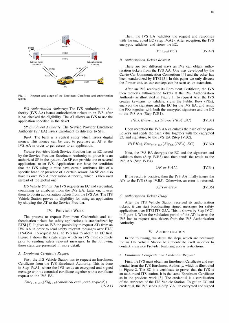
Fig. 1. Request and usage of the Enrolment Certificate and authorizationtickets
IVS Authorization Authority: The IVS Authorization Au-thority (IVS AA) issues authorization tickets to an IVS, afterit has checked the eligibility. The AT allows an IVS to use theapplication specified in the ticket.
SP Enrolment Authority: The Service Provider EnrolmentAuthority (SP EA) issues Enrolment Certificates to SPs.
Bank: The bank is a central entity which issues digitalmoney. This money can be used to purchase an AT at theIVS AA in order to get access to an application.
Service Provider: Each Service Provider has an EC issuedby the Service Provider Enrolment Authority to prove it is anauthorized SP in the system. An SP can provide one or severalapplications to an IVS. Applications can have the conditionthat the IVS using it must have certain attributes like of aspecific brand or presence of a certain sensor. An SP can alsohave its own IVS Authorization Authority, which is then usedinstead of the global one.
ITS Vehicle Station: An IVS requests an EC and credential,containing its attributes from the IVS EA. Later on, it usesthem to obtain authorization tickets from the IVS AA. The ITSVehicle Station proves its eligibility for using an applicationby showing the AT to the Service Provider.
IV. PREVIOUS WORK
The process to request Enrolment Credentials and au-thentication tickets for safety applications is standardized byETSI [3]. It gives an IVS the possibility to request ATs from anIVS AA in order to send safety relevant messages over ETSIITS-G5A. To request ATs, an IVS has to obtain an EC first.Figure 1 shows the single steps which an IVS must completeprior to sending safety relevant messages. In the followingthese steps are presented in more detail.
A. Enrolment Certificate Request
First, the ITS Vehicle Station has to request an EnrolmentCertificate from the IVS Enrolment Authority. This is donein Step IV.A1, where the IVS sends an encrypted and signedmessage with its canonical certificate together with a certificaterequest to the IVS EA.
EncIV S_EA(SigIV S(canonical cert., cert. request))(IV.A1)
Then, the IVS EA validates the request and responseswith the encrypted EC (Step IV.A2). After reception, the IVSencrypts, validates, and stores the EC.
EncEC(EC) (IV.A2)
B. Authorization Tickets Request
There are two different ways an IVS can obtain autho-rization tickets from the IVS AA. One was developed by theCar-to-Car Communication Consortium [4] and the other hasbeen standardized by ETSI [3]. In this paper we only discussthe former one, as our concept can be seen as an extension.
After an IVS received its Enrolment Certificate, the IVSthen requests authorization tickets at the IVS AuthorizationAuthority as illustrated in Figure 1. To request ATs, the IVScreates key-pairs to validate, signs the Public Keys (PKs),encrypts the signature and the EC for the IVS EA, and sendsthe PKs together with both the encrypted signature and the ECto the IVS AA (Step IV.B1).
PKs,EncIV S_EA(SigEC(PKs), EC) (IV.B1)
Upon reception the IVS AA calculates the hash of the pub-lic keys and sends the hash value together with the encryptedEC and signature, to the IVS EA (Step IV.B2).
H(PKs), EncIV S_EA(SigEC(PKs), EC) (IV.B2)
Next, the IVS EA decrypts the EC and the signature andvalidates them (Step IV.B3) and then sends the result to theIVS AA (Step IV.B4).
OK or FAIL (IV.B4)
If the result is positive, then the IVS AA finally issues theATs to the IVS (Step IV.B5). Otherwise, an error is returned.
ATs or error (IV.B5)
C. Authorization Tickets Usage
After the ITS Vehicle Station received its authorizationtickets, it can start broadcasting signed messages for safetyapplications over ETSI ITS G5A. This is shown by Step IV.C1in Figure 1. When the validation period of the ATs is over, theIVS has to request new tickets from the IVS AuthorizationAuthority.
V. AUTHENTICATION
In the following, we detail the steps which are necessaryfor an ITS Vehicle Station to authenticate itself in order tocontact a Service Provider featuring access restrictions.
A. Enrolment Certificate and Credential Request
First, the IVS must obtain an Enrolment Certificate and cre-dential from the IVS Enrolment Authority, which is illustratedin Figure 2. The EC is a certificate to prove, that the IVS isan authorized ITS station. It is the same Enrolment Certificateas in the previous work [3]. The credential is a certificationof the attributes of the ITS Vehicle Station. To get an EC andcredential, the IVS sends in Step V.A1 an encrypted and signed
10

Root CA
IVS AuthorizationAuthority
SP
SP EnrolmentAuthority
Bank IVS
IVS EnrolmentAuthority
(V.A1)
(V.A2)
(V.B1)
(V.B2)
Fig. 2. Request of the Enrolment Certificate, credential and money
message with its canonical certificate and a certificate requestto the IVS EA.
EncIV S_EA(SigIV S(canonical cert., cert. request))(V.A1)
Then, the IVS EA validates the request, issues the EC andcredential, and sends them encrypted to the IVS (Step V.A2).After reception, the IVS encrypts, validates, and stores them.
EncEC(EC,Credential) (V.A2)
B. Money Request
After the IVS received its EC and credential, it can requestdigital money from the bank as illustrated in Figure 2. Thiscan be done multiple times. Blind signatures can be usedfor digital money [5]. If blind signatures are used, the IVSgenerates random values, blinds them, and sends the blindedvalues together with its authorization to the bank in order torequest digital money (Step V.B1). The bank then blindly signsthe values, debits the bank account of the driver, and returnsthe blind signed values back to the IVS (Step V.B2).
blinded_values, auth_info (V.B1)
digital_money (V.B2)
The IVS now has digital money from the bank, which canbe used to pay for applications.
C. Attribute-Based Authorization Ticket Request
The ITS Vehicle Station can now request attribute-basedauthorization tickets to use specific applications, with the helpof its Enrolment Certificate, credential and, if necessary, thedigital money from the IVS Authorization Authority. Whenrequesting attribute-based ATs, the IVS first checks if theattributes necessary for the application are present as illustratedin Figure 3 (Step V.C1).
Now, the IVS encrypts the hash of its EC for the IVSEA. Then it derives a token containing the necessary attributesand a proof for the ciphertext. Afterwards it creates the keypairs to sign. Now it signs the name of the application andthe public keys to certify. This signature is then, together with
Root CA
IVS AuthorizationAuthority
SP
SP EnrolmentAuthority
IVS
IVS EnrolmentAuthority
(V.C1)
(V.C8)
(V.C3)
(V.C4)
(V.C5)
(V.C6)
(V.C7)(V.C2)
Bank
Fig. 3. Request of attribute-based authorization tickets
the EC, encrypted for the IVS EA. Finally, the IVS sends theapplication name, the encrypted parts, the token, the PKs, andthe necessary money to the IVS AA (Step V.C2).
app_name,EncIV S_EA(SigEC(app_name, PKs), EC),
EncIV S_EA(hash), tokenattr+hash, PKs, digital_money(V.C2)
On reception, the IVS AA validates the token and sendsthe encrypted parts together with a hash over the applicationname and the public keys to the IVS EA (Step V.C3).
H(app_name, PKs), EncIV S_EA(hash),
EncIV S_EA(SigEC(app_name, PKs), EC)(V.C3)
The IVS EA encrypts everything and checks in Step V.C4if the EC and the signature are valid and if the hash fits thisEC. Afterwards, the IVS EA returns the result of this validationto the IVS AA. (Step V.C5)
OK or FAIL (V.C5)
If the validation was successful and the IVS has to pay forthe application usage, the IVS AA forwards the digital moneyfrom the IVS to the bank (Step V.C6). There the money istransfered to the the account of the IVS Authorization Au-thority. Subsequently, the bank returns the validity information(Step V.C7).
digital_money (V.C6)
OK or FAIL (V.C7)
Finally, the IVS AA issues the attribute-based authorizationtickets for the application to the IVS (Step V.C8), if allprevious steps were executed successfully. Otherwise an erroris transmitted.
ATsapp_name or error (V.C8)
The outlined system supports two different kinds of billing- per request or per time period. If the IVS has to pay perrequest, each AT can be used for one request only. When theIVS uses an AT to access an application, the AT is revokedimmediately at the SP to prevent further usage. The IVS getsas many ATs as it has payed for. When per time period billing
11
Root CA
IVS AuthorizationAuthority
SP
SP EnrolmentAuthority
IVS
IVS EnrolmentAuthority
Use service with AT
Bank
Fig. 4. Application usage
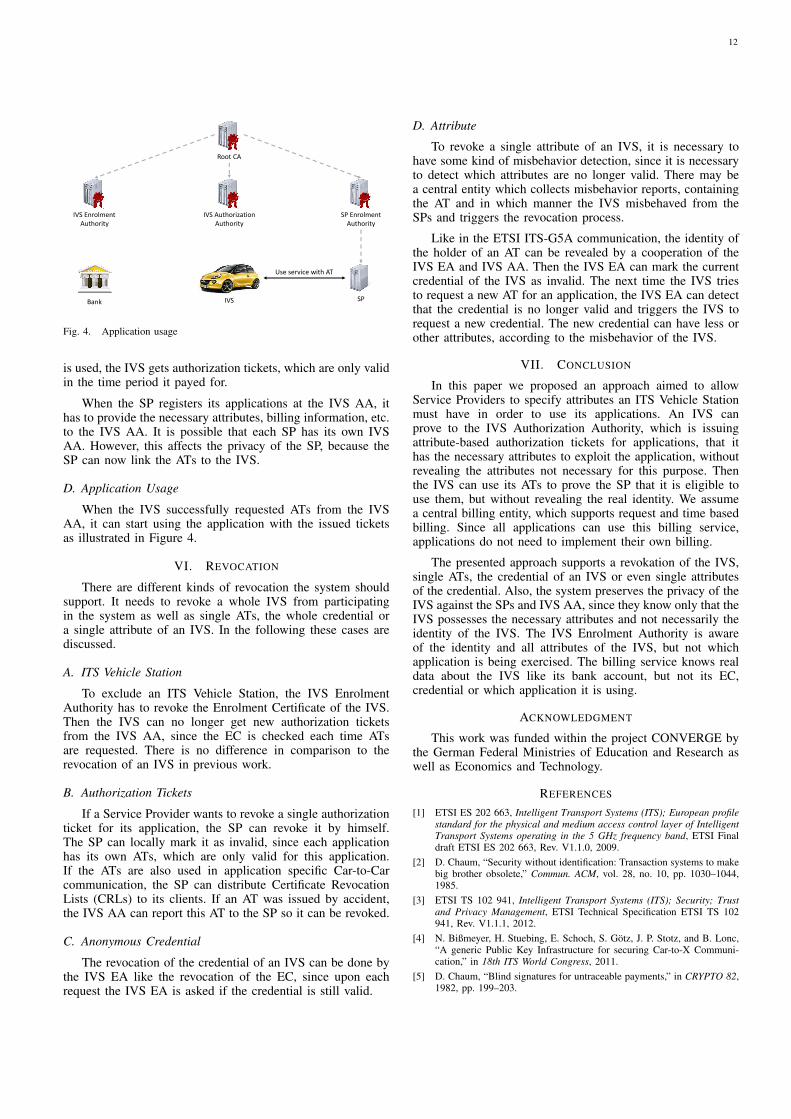
is used, the IVS gets authorization tickets, which are only validin the time period it payed for.
When the SP registers its applications at the IVS AA, ithas to provide the necessary attributes, billing information, etc.to the IVS AA. It is possible that each SP has its own IVSAA. However, this affects the privacy of the SP, because theSP can now link the ATs to the IVS.
D. Application Usage
When the IVS successfully requested ATs from the IVSAA, it can start using the application with the issued ticketsas illustrated in Figure 4.
VI. REVOCATION
There are different kinds of revocation the system shouldsupport. It needs to revoke a whole IVS from participatingin the system as well as single ATs, the whole credential ora single attribute of an IVS. In the following these cases arediscussed.
A. ITS Vehicle Station
To exclude an ITS Vehicle Station, the IVS EnrolmentAuthority has to revoke the Enrolment Certificate of the IVS.Then the IVS can no longer get new authorization ticketsfrom the IVS AA, since the EC is checked each time ATsare requested. There is no difference in comparison to therevocation of an IVS in previous work.
B. Authorization Tickets
If a Service Provider wants to revoke a single authorizationticket for its application, the SP can revoke it by himself.The SP can locally mark it as invalid, since each applicationhas its own ATs, which are only valid for this application.If the ATs are also used in application specific Car-to-Carcommunication, the SP can distribute Certificate RevocationLists (CRLs) to its clients. If an AT was issued by accident,the IVS AA can report this AT to the SP so it can be revoked.
C. Anonymous Credential
The revocation of the credential of an IVS can be done bythe IVS EA like the revocation of the EC, since upon eachrequest the IVS EA is asked if the credential is still valid.
D. Attribute
To revoke a single attribute of an IVS, it is necessary tohave some kind of misbehavior detection, since it is necessaryto detect which attributes are no longer valid. There may bea central entity which collects misbehavior reports, containingthe AT and in which manner the IVS misbehaved from theSPs and triggers the revocation process.
Like in the ETSI ITS-G5A communication, the identity ofthe holder of an AT can be revealed by a cooperation of theIVS EA and IVS AA. Then the IVS EA can mark the currentcredential of the IVS as invalid. The next time the IVS triesto request a new AT for an application, the IVS EA can detectthat the credential is no longer valid and triggers the IVS torequest a new credential. The new credential can have less orother attributes, according to the misbehavior of the IVS.
VII. CONCLUSION
In this paper we proposed an approach aimed to allowService Providers to specify attributes an ITS Vehicle Stationmust have in order to use its applications. An IVS canprove to the IVS Authorization Authority, which is issuingattribute-based authorization tickets for applications, that ithas the necessary attributes to exploit the application, withoutrevealing the attributes not necessary for this purpose. Thenthe IVS can use its ATs to prove the SP that it is eligible touse them, but without revealing the real identity. We assumea central billing entity, which supports request and time basedbilling. Since all applications can use this billing service,applications do not need to implement their own billing.
The presented approach supports a revokation of the IVS,single ATs, the credential of an IVS or even single attributesof the credential. Also, the system preserves the privacy of theIVS against the SPs and IVS AA, since they know only that theIVS possesses the necessary attributes and not necessarily theidentity of the IVS. The IVS Enrolment Authority is awareof the identity and all attributes of the IVS, but not whichapplication is being exercised. The billing service knows realdata about the IVS like its bank account, but not its EC,credential or which application it is using.
ACKNOWLEDGMENT
This work was funded within the project CONVERGE bythe German Federal Ministries of Education and Research aswell as Economics and Technology.
REFERENCES
[1] ETSI ES 202 663, Intelligent Transport Systems (ITS); European profilestandard for the physical and medium access control layer of IntelligentTransport Systems operating in the 5 GHz frequency band, ETSI Finaldraft ETSI ES 202 663, Rev. V1.1.0, 2009.
[2] D. Chaum, “Security without identification: Transaction systems to makebig brother obsolete,” Commun. ACM, vol. 28, no. 10, pp. 1030–1044,1985.
[3] ETSI TS 102 941, Intelligent Transport Systems (ITS); Security; Trustand Privacy Management, ETSI Technical Specification ETSI TS 102941, Rev. V1.1.1, 2012.
[4] N. Bißmeyer, H. Stuebing, E. Schoch, S. Götz, J. P. Stotz, and B. Lonc,“A generic Public Key Infrastructure for securing Car-to-X Communi-cation,” in 18th ITS World Congress, 2011.
[5] D. Chaum, “Blind signatures for untraceable payments,” in CRYPTO 82,1982, pp. 199–203.
12

Towards the City-scale Simulation and PerformanceAssessment of Electric Vehicles
Ekaterina Masalkina, David Eckhoff, Rudiger Berndt and Reinhard GermanComputer Networks and Communication Systems
Dept. of Computer Science, University of Erlangen, Germany{ekaterina.masalkina,david.eckhoff,ruediger.berndt,reinhard.german}@fau.de
Abstract—Electric vehicles are believed to soon play an im-portant role in urban traffic. In order to fully understand theirperformance in terms of range and battery management large-scale simulations can offer valuable insights. In this work wepresent a simulation framework to study these and other aspectsof future mobility.
We develop a computationally inexpensive battery and energyconsumption model that accounts for rolling and air resistancesand only requires preset constant parameters and speed updatesof a vehicle to compute the battery’s State of Charge. Wefurthermore show that—based on real map data—it is possible toconduct city-scale simulations with 100 000 vehicles to investigatea wide range of effects considering an increasing proportion ofelectric vehicles. Finally, the framework also allows to investigatebattery management strategies which are based upon inter-vehicle communication.
Index Terms—Electromobility; IVC; lithium-ion battery model
I. INTRODUCTION
The absence of direct CO2 emission makes electric vehiclesa promising approach to lower pollution and reduce the CO2
footprint. Therefore, the German Government released plansto increase the number of electric vehicles on German roadsto 1 million by the year 2020 [1]. To reach this goal, themain challenge for electric vehicles has to be overcome: theirlimited range. One approach is to use rechargeable lithium-ionbatteries; given a high energy density and low self-dischargerate, they can boost the effectiveness and thereby the popularityof electric cars. Unfortunately, the performance of lithium-ion batteries deteriorates over time [2], caused by age andthe number of charge cycles. One possible solution for thisproblem is advanced battery management [3].
Fully understanding the effects of different managementstrategies from Field Operational Test (FOT) is a cost-intensiveand time-consuming approach. Large-scale simulations offera promising solution to this problem, however, they requirerealistic traffic and battery models in order to produce meaning-ful results. Especially when battery management includes theutilization of inter-vehicle communication [3], a comprehensivesimulation framework can help predict the batteries’ behaviorunder numerous conditions and to find approaches for extendingthe batteries’ life-times.
In this paper, we present our work towards such a framework.Our contribution can be summarized as follows:
• We present a computationally efficient battery and energyconsumption model that only requires preset engine
parameters and data obtained by a microscopic trafficsimulator
• We show how to conduct city-scale traffic simulationusing SUMO and the OMNeT++ simulator to examine(potentially aided by wireless communication) batterymanagement strategies.
• We discuss possible directions where inter-vehicularcommunication can help extend battery life-time.
II. RELATED WORK
Lithium-ion battery modeling has been subject to numerousstudies.
The authors of [4] present a behavioral lithium-ion batterymodel in a general sense without going into kinematic details.They discuss the dependency of the battery discharge capacityon the discharge rate and temperature. In [3] Tielert et al.analyse how ambient temperature, road gradient, auxiliaryconsumers and driver behavior impact the energy consumptionof electric vehicles [3]. They study how vehicular networks, inparticular traffic-light-to-vehicle communication, can decreasebattery energy consumption and find that electric cars couldprofit from longer information distances. By doubling theinformation distance from 300m to 600m up to tripled batteryenergy savings were observed.
Using the presented battery model, we aim to furtherinvestigate the possibilities of wireless communication in city-scale simulations. In this work we perform the simulation ofelectric vehicles on city roads, implement a battery module andbuild it in our simulation setup. This enables us to evaluatethe traffic flow, vehicular networks and the impact of differentfactors on the battery State of Charge (SOC) simultaneously.
III. BATTERY MODEL
This section describes our computationally inexpensivebattery and energy consumption model that only requires presetengine parameters and that can operate solely on vehiclesspeeds, for example obtained by a microscopic traffic simulator.At this stage the model of lithium-ion battery is temperatureindependent and does not account for battery recuperation orroad gradients. These extensions are subject of future work.
In each time step of the traffic simulation, the SOC iscomputed as a function of the vehicle speed ~v, the acceleration~a and the angular speed of the wheels ~wR (see Figure 1).However, given only ~v, the acceleration ~a is found as a rate
13
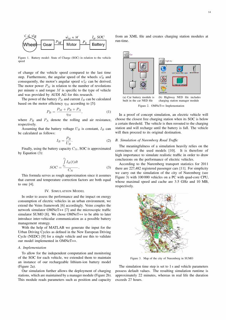
Figure 1. Battery model: State of Charge (SOC) in relation to the vehiclespeed
of change of the vehicle speed compared to the last timestep. Furthermore, the angular speed of the wheels ~wR andconsequently, the motor’s angular speed ~wM can be derived.The motor power PM in relation to the number of revolutionsper minute n and torque M is specific to the type of vehicleand was provided by AUDI AG for this research.
The power of the battery PB and current IB can be calculatedbased on the motor efficiency ηM according to [5]:
PB =PM + PR + PA
ηM, (1)
where PR and PA denote the rolling and air resistance,respectively.
Assuming that the battery voltage UB is constant, IB canbe calculated as follows:
IB =PB
UB. (2)
Finally, using the battery capacity CN , SOC is approximatedby Equation (3):
SOC =
t1∫t0
IB(t)dt
CN. (3)
This formula serves as rough approximation since it assumesthat current and temperature correction factors are both equalto one [4].
IV. SIMULATION MODEL
In order to assess the performance and the impact on energyconsumption of electric vehicles in an urban environment, weextend the Veins framework [6] accordingly. Veins couples thenetwork simulator OMNeT++ [7] and the microscopic trafficsimulator SUMO [8]. We chose OMNeT++ to be able to laterintroduce inter-vehicular communication as a possible batterymanagement strategy.
With the help of MATLAB we generate the input for theUrban Driving Cycles as defined in the New European DrivingCycle (NEDC) [9] for a single vehicle and use this to validateour model implemented in OMNeT++.
A. Implementation
To allow for the independent computation and monitoringof the SOC for each vehicle, we extended them to maintainan instance of our rechargeable lithium-ion battery model(Figure 2a).
Our simulation further allows the deployment of chargingstations, which are maintained by a manager module (Figure 2b).This module reads parameters such as position and capacity
from an XML file and creates charging station modules atrun-time.
(a) Car battery module isbuilt in the car NED file
(b) Highway NED file includescharging station manager module
Figure 2. OMNeT++ Implementation
In a proof of concept simulation, an electric vehicle willchoose the closest free charging station when its SOC is belowa certain threshold. The vehicle is then rerouted to the chargingstation and will recharge until the battery is full. The vehiclewill then proceed to its original destination.
B. Simulation of Nuremberg Road Traffic
The meaningfulness of a simulation heavily relies on thecorrectness of the used models [10]. It is therefore ofhigh importance to simulate realistic traffic in order to drawconclusions on the performance of electric vehicles.
According to the Nuremberg transport statistics for 2011there are 227,482 registered passenger cars [11]. For simplicitywe carry out the simulation of the city of Nuremberg (seeFigure 3) with 100 000 vehicles on a PC with quad-core CPU,whose maximal speed and cache are 3.5 GHz and 10 MB,respectively.
Figure 3. Map of the city of Nuremberg in SUMO
The simulation time step is set to 1 s and vehicle parameterspossess default values. The resulting simulation runtime isapproximately 22 minutes, whereas in real life the durationexceeds 27 hours.
14

To also investigate the performance of electric vehicles, westarted by simulating one electric vehicle in a smaller sectionof the map (see Figure 4). The distance between the start anddestination points of the route is about 3.5 km. We placed twocharging stations in close proximity to the chosen route.
One possible outcome of such simulations is an approxima-tion of the optimal positioning of charging stations. In a firststep we assume that regular gas stations are also equipped withplug charging connectors for electric cars. This allows us todraw conclusions whether (and how many) additional chargingstations are required considering a desired maximum waitingtime.
Figure 4. Individually simulated electric vehicle on the Nuremberg map
V. SIMULATION RESULTS
Figure 5 shows an example SOC curve of an individuallysimulated electric vehicle on the Nuremberg map. It can beseen that after 377 s with an average speed of 10.8 m/s anda top speed of 14 m/s the SOC is reduced by less than 7 %(corresponding to 0.84 kW h).
To prove the correctness of our OMNeT++ model we usedthe SUMO mobility trace as an input to the MATLAB model.The comparison of the SOC behavior in Veins and MATLABsimulation models shows no difference.
Figure 5. Speed and State of Charge of one individually simulated electricvehicle
In a second simulation, we use our battery model to simulatea typical urban driving cycle as defined by the NEDC [9].Figure 6 can be seen as a benchmark for the comparison againstother battery models and to investigate the effect of futurefeatures such as recuperation and temperature dependency. It
Figure 6. Speed, energy consumption and state of charge of a vehicle’s runthrough the NEDC
also allows us to validate our model based on data from realexperiments. We observe that after 780 s and a covered distanceof 4067 m the battery is drained by less than 7 %.
VI. INTER-VEHICULAR COMMUNICATION
The communication among vehicles and between vehiclesand infrastructure can be a promising tool to further reducebattery drain and thereby increase the range of electric vehi-cles. For example, Green Light Optimized Speed Advisorysystems [4], [12] and vehicular communication based on IEEE802.11p [13] and/or UMTS/LTE cannot only be used to avoidunnecessary stops but also to choose an optimal recuperationstage to obtain the best possible energy gain.
But also other vehicles can provide valuable information:for example, a car driving ahead can inform the electric vehicleabout its deceleration rate or planned lane changes to avoidan energetic suboptimal driving maneuver and again aid inchoosing the correct recuperation stage.
Vehicular networks can also be helpful in reducing thewaiting times at charging stations for electric cars. Receivinginformation about the location and current occupancy ofcharging stations could enable drivers of electric vehicles toreserve a spot at the most suitable charging station in advance.
VII. CONCLUSION AND FUTURE WORK
In this work we introduce a computationally inexpensivelithium-ion battery and energy consumption model whichconsiders rolling and air resistance and is only based onpredefined engine parameters and speed of a vehicle. Wepresented a simulation model, which is used to simulateelectric vehicles in the city of Nuremberg and investigate theirperformance together with their impact on energy consumption.The simulation results show that the developed model can beused to further study the performance of electric vehicles undercertain conditions.
Future work will concentrate on extending model to alsoaccount for recuperation as well as the influence of ambienttemperature. Furthermore we will focus on the simulation ofrealistic city-wide traffic based on empiric data to evaluatethe impact of the substitution of common combustion engine
15

vehicles with their electric counterparts. Based on these steps,we will then investigate possible benefits of inter-vehicularcommunication on battery management.
ACKNOWLEDGEMENT
This work is funded by the German national programSchaufenster Elektromobilitat, e-NUE. We would like to thankAUDI AG and N-ERGIE Aktiengesellschaft for providing thenecessary data to conduct this research.
REFERENCES
[1] The German Federal Government, “German Federal Government’sNational Electromobility Development Plan,” press release, August 2009.
[2] J. Vetter, P. Novak, M. R. Wagner, C. Veit, K.-C. Moller, J. O. Besenhard,M. Winter, M. Wohlfahrt-Mehrens, C. Vogler, and A. Hammouche,“Ageing mechanisms in lithium-ion batteries,” Journal of Power Sources,vol. 147, pp. 269–281, September 2005.
[3] T. Tielert, D. Rieger, H. Hartenstein, R. Luz, and H. Hausberger,“Can V2X Communication Help Electric Vehicles Save Energy?” in12th International Conference on ITS Telecommunications (ITST 2012).Taipei, Taiwan: IEEE, November 2012, pp. 232–237.
[4] L. Gao, S. Liu, and R. A. Dougal, “Dynamic Lithium-ion BatteryModel for System Simulation,” IEEE Transactions on Components andPackaging Technologies, vol. 25, no. 3, pp. 495–505, September 2002.
[5] D. G. Fink and J. M. Carroll, Handbook for Electrical Engineers.McGraw-Hill Inc, October 1978.
[6] C. Sommer, R. German, and F. Dressler, “Bidirectionally CoupledNetwork and Road Traffic Simulation for Improved IVC Analysis,” IEEETransactions on Mobile Computing, vol. 10, no. 1, pp. 3–15, January2011.
[7] A. Varga and R. Hornig, “An overview of the OMNeT++ simulationenvironment,” in 1st ACM/ICST International Conference on SimulationTools and Techniques for Communications, Networks and Systems(SIMUTools 2008). Marseille, France: ACM, March 2008.
[8] D. Krajzewicz, G. Hertkorn, C. Rossel, and P. Wagner, “SUMO(Simulation of Urban MObility); An Open-source Traffic Simulation,”in 4th Middle East Symposium on Simulation and Modelling (MESM2002), Sharjah, United Arab Emirates, September 2002, pp. 183–187.
[9] “Council Directive 91/441/EEC of 26 June 1991 amending Directive70/220/EEC on the approximation of the laws of the Member Statesrelating to measures to be taken against air pollution by emissions frommotor vehicles,” The Council of the European Communities, Directive91/441/EEC, June 1991.
[10] F. Dressler, C. Sommer, D. Eckhoff, and O. K. Tonguz, “Towards Real-istic Simulation of Inter-Vehicle Communication: Models, Techniquesand Pitfalls,” IEEE Vehicular Technology Magazine, vol. 6, no. 3, pp.43–51, September 2011.
[11] Stadt Nurnberg, “Auszug der Bezirkstabellen und Karten aus denInnergebietlichen Strukturdaten Nurnberg 2012,” Amt fur Stadtforschungund Statistik, Innergebietliche Strukturdaten Nurnberg 2012, December2012.
[12] D. Eckhoff, B. Halmos, and R. German, “Potentials and Limitations ofGreen Light Optimal Speed Advisory Systems,” in 5th IEEE VehicularNetworking Conference (VNC 2013). Boston, MA: IEEE, December2013, pp. 103–110.
[13] “Wireless Access in Vehicular Environments,” IEEE, Std 802.11p-2010,July 2010.
16

In-car communication based on power line networks
Thomas GehrsitzInstitute for Communication Networks
Technische Universitat MunchenMunchen, Germany
Wolfgang KellererInstitute for Communication Networks
Technische Universitat MunchenMunchen, Germany
Helmut KellermannBMW Research and Technology
Munchen, [email protected]
Abstract—The number of electronic control units in today’scars is permanently increasing. As the demand for informationexchange between these units is also increasing, the complexityof the in-car communication infrastructure also increases. In thepast more and more bus-segments have been added to cope withthe growing demands. In order to reduce the complexity andthe costs for the future in-car communication infrastructure,the approach of using power line communication for the in-car communication has been analyzed. By using power linecommunication, the cabling can be reduced to the minimum.In this paper the challenges of today’s and the requirement forfuture in-car systems are summarized. The HomePlug GreenPHY standard, which has been designed for smart grid applica-tions, will be analyzed according to its applicability to the in-carcommunication. A proposal and its evaluation for the reductionof the overhead will be presented.
I. INTRODUCTION
In the past decades the demand for information exchangebetween ECUs (electronic control units) in vehicles rapidlyraised. Prior to the digital data transmission, mainly electricalsignals have been used for the information exchange. Withthe increasing number of safety and comfort functions, thedemand for a data exchange between a huge number ofECUs increases from vehicle generation to vehicle generation.Over the years different communication systems emerged fordifferent applications.
In the 1980s the CAN-bus (controller area network) [1]has been designed and released. The CAN bus was one of thefirst widely spread communication busses in vehicles. With anincrease in body and comfort functions, the wish for a cheapand simple communication system came up. For this purposethe LIN-bus (local interconnect network) [2] has been defined.It is mainly used for the body and comfort functions wheresafety requirements are typically low and no high data ratesare needed. In the beginning of the 21 century the requirementfor a new in-car communication system came up. FlexRay[3] has been designed to provide a communication system fortime-critical functions like safety functions.
In a today’s upper class vehicle more than 40-50 ofthese communication busses can be found. This introduceschallenges in planning, deployment and the maintenance ofthe harness. Additionally the high number of wires lead tohigher costs and also weight, which directly translates in fuelconsumption.
The highest rate of changes is typically observed in thebody and comfort area, where the LIN-bus is dominant. Upperclass vehicles already contain up to 20-30 of these busses
distributed over the whole vehicle. If information has to betransmitted to another LIN-bus, gateways have to be used.
One possibility to reduce the cabling of the ECUs is theusage of wireless communication. But with wireless commu-nication additional challenges arise. The interference to andfrom other devices in the surrounding of the vehicle have tobe considered. Measurements [4] have shown, that the effectivearea of influence is quite large. The positioning of the antennahas to be chosen carefully and the transmit power should beas low as possible.
Another possibility is the application of power line com-munication (PLC). With PLC the need for dedicated commu-nication lines besides the power line disappears. Thereby thecabling will be reduced to the minimum - the power supply.Measurements [5] have shown, that the physical transmissionof PLC signals on a car body is possible. But the EMC still hasto be investigated in order to meet automotive requirements.
Various PLC standards for the in-house application likeG.hn or HomePlug AV are available. The latter one hasbeen investigated according to its applicability for the in-carcommunication.
In this paper, starting from a today’s vehicle, the challengesand requirements for the future in-car communication will bestated. The HomePlug Green PHY standard will be examinedaccording to its applicability for the in-car communication.
In section II a short overview on a today’s in-car communi-cation infrastructure will be given. In Section III requirementsfor a future in-car PLC communication protocol will belisted. Section IV will summarize the main features of theHomePlug Green PHY standard and its applicability for the in-car communication will be discussed. In section V simulationresults with a modified protocol are presented. A conclusionwill be given in section VI.
II. TODAY’S IN-CAR COMMUNICATION
[Final paper content: Overview on the in-car commu-nication infrastructure, commonly used bus-systems]
Today’s cars include highly interconnected ECUs coveringa wide rage of applications. Upper class vehicles - dependingon the configuration of the features - may contain up to 50-100 ECUs. Besides these ECUs there are also sensors andactuators, which have to be connected. The cabling needed forthe interconnection of the ECUs easily reaches summed uplength of more than 1-2 km. Widely spread bus-systems whichcan be found in such a vehicle are: CAN, LIN and FlexRay.
17

Multiple busses of each type are typically deployed in a carand most of them are interconnected by a gateway. As a highrate of change from vehicle generation to vehicle generation isin the body and comfort area where the LIN-bus is dominant,the focus of this paper is to replace the LIN-infrastructureby a PLC-system. The low safety-requirements on the LIN-bus are another reason for choosing its replacement in a firstrealization.
The LIN-bus is a comparatively cheap bus-system mostlyused for non safety-critical communication in the body andcomfort domain. The maximum data rate is 20 kbit/s. How-ever the possible savings of replacing the LIN-infrastructure byPLC is quite high, because of the high number of LIN-bussesin a car covering almost every part of the vehicle. A today’supper class vehicle already includes over 20 LIN-busses, whichcomes along with a very high effort in wiring.
The high number of LIN-busses lead to various challenges.The increasing complexity enlarges the effort in planning,installation, management and the diagnosis of the harness. Theweight is also increasing which directly translates into a higherfuel consumption.
III. PLC FOR THE IN-CAR COMMUNICATION
[Final paper content: PLC protocol requirements forthe future in-car communication infrastructure]
The requirements for the in-car communication differ fromtypical home area networks (HANs). Typical HANs consist ofa small number of nodes interconnected by a network withcomparably high data rate. For a high throughput, the framestypically carry some hundred bytes in order to reduce theoverhead. For the in-car communication in contrast, a highnumber of nodes has to be connected while the exchangedinformation is typically in the range of only 1-8 byte. Thusa protocol for the in-car communication should be able tosupport a high number of nodes while minimizing the overheadfor the short payloads.
Most protocols for the home and wide area networksare non-deterministic. Regarding diagnosis, determinism is adesirable property for in-car communication systems.
Another point is the quality of service (QoS). Most proto-cols support a kind of QoS but for the in-car communicationsome functions have strict requirements regarding the latency.Functions like control loops often produce periodic trafficeither continuously or at least for a period of time.
Thus a protocol should be suitable to transport periodictraffic on the one hand and support event based traffic on theother hand.
The requirements for a in-car communication system canroughly be summarized as follows:
• Scalability: The protocol has to be able to handle ahigh number of nodes (one hundred or even more)
• The overhead has to be minimized; in case of the LIN-bus the payload will be less or equal to 8 byte
• Determinism is a desired feature (at least for periodictraffic)
TABLE I. HOMEPLUG GREEN PHY ROBO MODES
mode PHY rate # copies PHY block
Mini-ROBO 3.8 Mbit/s 5 PB136
Standard-ROBO 4.9 Mbit/s 4 PB520
High Speed ROBO 9.8 Mbit/s 2 PB520
• Support for periodic traffic and additionally supportfor event based traffic
IV. IEEE 1901 AND HOMEPLUG GREEN PHY
[Final paper content: Short introduction in IEEE 1901and the HomePlug standard, protocol overhead whenusing the HomePlug Green PHY standard, solution toreduce the overhead by using the frame control for frametransmission]
The IEEE 1901 standard [6] has been defined to providecoexistence between different PLC standards. Thus IEEE 1901includes the HomePlug standard. In the following a briefoverview on the HomePlug standard will be given.
The HomePlug 1.0 standard has been released in 2001by the HomePlug Alliance. HomePlug AV as an extensionhas been released in 2005. HomePlug AV currently supportsdata rates up to 500 Mbit/s. The new HomePlug AV2 standardalready supports data rates of approximately 1 Gbit/s.
For Smart Grid applications the HomePlug Green PHY(HP GP) standard has also been released in 2005. HomePlugGreen PHY is a subset of the HomePlug AV standard with thefocus on a robust communication. The robustness is reached byusing only QPSK modulation and using the so-called ROBO(robust) modes. With the ROBO modes multiple copies of thesame signal are simultaneously transmitted over the OFDM(orthogonal frequency division multiplex) carriers.
For the organization and synchronization of a network onenode is selected to act as a central coordinator (CCo). TheCCo periodically sends beacons to synchronize the network.In between beacons two medium access methods can be used.The first one is the mandatory CSMA which uses a backoff-mechanism for collision avoidance. The optional TDMA is thesecond access method. In the TDMA access period, stationscan ask the CCo for a reservation of transmission time.
As a dynamic reservation of transmission time accordingto the HomePlug AV standard is not a suitable solution for thein-car communication, only CSMA is considered in this paper.
In table I, the HomePlug Green PHY ROBO modes arelisted. In the last column the physical block size is shown.PB136 denotes a physical block with 136 byte length, PB520corresponds to a physical block with 520 byte in length. ThesePBs are the smallest amount of data which will be transmittedon the channel. Each PB consists of a PB header and a PBcheck sequence (each 4 byte in length). For a PB136 this leadsto a PB payload (PB body) of 128 byte. In this payload theMAC protocol data unit (MPDU) is transported. A MAC frameconsists of a 2 byte header and a 4 byte checksum. In the caseof a PB136 this leads to a MAC payload of 122 byte.
Considering typical in-car frame length of up to 8 byte,even the usage of the smallest PHY block size of 136 byte
18
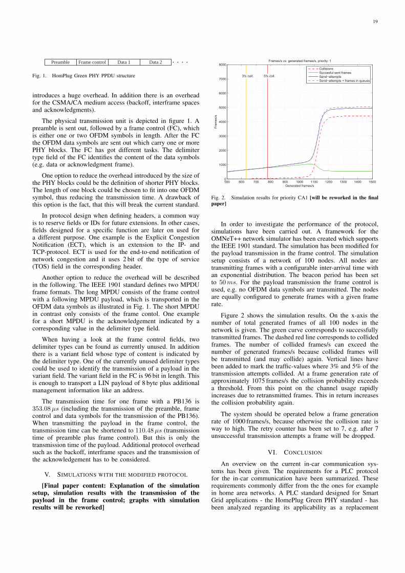
Preamble Frame control Data 1 Data 2
Fig. 1. HomPlug Green PHY PPDU structure
introduces a huge overhead. In addition there is an overheadfor the CSMA/CA medium access (backoff, interframe spacesand acknowledgments).
The physical transmission unit is depicted in figure 1. Apreamble is sent out, followed by a frame control (FC), whichis either one or two OFDM symbols in length. After the FCthe OFDM data symbols are sent out which carry one or morePHY blocks. The FC has got different tasks. The delimitertype field of the FC identifies the content of the data symbols(e.g. data or acknowledgment frame).
One option to reduce the overhead introduced by the size ofthe PHY blocks could be the definition of shorter PHY blocks.The length of one block could be chosen to fit into one OFDMsymbol, thus reducing the transmission time. A drawback ofthis option is the fact, that this will break the current standard.
In protocol design when defining headers, a common wayis to reserve fields or IDs for future extensions. In other cases,fields designed for a specific function are later on used fora different purpose. One example is the Explicit CongestionNotification (ECT), which is an extension to the IP- andTCP-protocol. ECT is used for the end-to-end notification ofnetwork congestion and it uses 2 bit of the type of service(TOS) field in the corresponding header.
Another option to reduce the overhead will be describedin the following. The IEEE 1901 standard defines two MPDUframe formats. The long MPDU consists of the frame controlwith a following MPDU payload, which is transported in theOFDM data symbols as illustrated in Fig. 1. The short MPDUin contrast only consists of the frame contol. One examplefor a short MPDU is the acknowledgement indicated by acorresponding value in the delimiter type field.
When having a look at the frame control fields, twodelimiter types can be found as currently unused. In additionthere is a variant field whose type of content is indicated bythe delimiter type. One of the currently unused delimiter typescould be used to identify the transmission of a payload in thevariant field. The variant field in the FC is 96 bit in length. Thisis enough to transport a LIN payload of 8 byte plus additionalmanagement information like an address.
The transmission time for one frame with a PB136 is353.08µs (including the transmission of the preamble, framecontrol and data symbols for the transmission of the PB136).When transmitting the payload in the frame control, thetransmission time can be shortened to 110.48µs (transmissiontime of preamble plus frame control). But this is only thetransmission time of the payload. Additional protocol overheadsuch as the backoff, interframe spaces and the transmission ofthe acknowledgement has to be considered.
V. SIMULATIONS WITH THE MODIFIED PROTOCOL
[Final paper content: Explanation of the simulationsetup, simulation results with the transmission of thepayload in the frame control; graphs with simulationresults will be reworked]
500 600 700 800 900 1000 1100 1200 1300 1400 15000
1000
2000
3000
4000
5000
6000
7000
8000
Generated frames/s
Fram
es/s
Frames/s vs. generated frames/s, priority: 1
3% coll. 5% coll.
CollisionsSuccesful sent framesSend−attemptsSend−attempts + frames in queues
Fig. 2. Simulation results for priority CA1 [will be reworked in the finalpaper]
In order to investigate the performance of the protocol,simulations have been carried out. A framework for theOMNeT++ network simulator has been created which supportsthe IEEE 1901 standard. The simulation has been modified forthe payload transmission in the frame control. The simulationsetup consists of a network of 100 nodes. All nodes aretransmitting frames with a configurable inter-arrival time withan exponential distribution. The beacon period has been setto 50ms. For the payload transmission the frame control isused, e.g. no OFDM data symbols are transmitted. The nodesare equally configured to generate frames with a given framerate.
Figure 2 shows the simulation results. On the x-axis thenumber of total generated frames of all 100 nodes in thenetwork is given. The green curve corresponds to successfullytransmitted frames. The dashed red line corresponds to collidedframes. The number of collided frames/s can exceed thenumber of generated frames/s because collided frames willbe transmitted (and may collide) again. Vertical lines havebeen added to mark the traffic-values where 3% and 5% of thetransmission attempts collided. At a frame generation rate ofapproximately 1075 frames/s the collision probability exceedsa threshold. From this point on the channel usage rapidlyincreases due to retransmitted frames. This in return increasesthe collision probability again.
The system should be operated below a frame generationrate of 1000 frames/s, because otherwise the collision rate isway to high. The retry counter has been set to 7, e.g. after 7unsuccessful transmission attempts a frame will be dropped.
VI. CONCLUSION
An overview on the current in-car communication sys-tems has been given. The requirements for a PLC protocolfor the in-car communication have been summarized. Theserequirements commonly differ from the the ones for examplein home area networks. A PLC standard designed for SmartGrid applications - the HomePlug Green PHY standard - hasbeen analyzed regarding its applicability as a replacement
19

for the LIN-bus. Even though the HomePlug Green PHYstandard has been designed for Smart Grid applications, theminimum MAC payload is 122 byte when using the smallestPHY block size (PB136). Currently the payload length ofa LIN or a CAN frame is limited to 8 byte which is farbelow the minimum payload of a Green PHY frame. In orderto reduce the overhead, the transmission of the payload inthe variant field of the frame control has been suggested.Thereby the transmission time of one frame can be reducedfrom 353.08µs to 110.48µs. Simulations have shown, thatthe additional protocol overhead (backoff, interframe spacesand acknowledgements) still produce a huge overhead. Thecollision probability increases with increasing traffic load.Thus using a pure CSMA/CA medium access might not meetthe requirements for some applications. If this is the case, thecombination of CSMA/CA and TDMA might be a solution,as defined in the HomePlug AV standard.
REFERENCES
[1] “CAN specification version 2.0,” Robert Bosch GmbH, 1991.[2] “LIN specification package revision 2.1,” LIN Consortium, 2006.[3] “Flexray protocol specification v3.0.1,” Flexray Consortium, 2010.[4] M. Blesinger, E. Biebl, T. Gehrsitz, J. Eberspacher, P. Fertl, O. Klemp,
and H. Kellermann, “Angle-dependent path loss measurements impactedby car body attenuation in 2.45 ghz ism band,” in Vehicular TechnologyConference (VTC Spring), 2012 IEEE 75th, 2012, pp. 1–5.
[5] M. Lienard, M. Carrion, V. Degardin, and P. Degauque, “Modeling andanalysis of in-vehicle power line communication channels,” VehicularTechnology, IEEE Transactions on, vol. 57, no. 2, pp. 670–679, 2008.
[6] “IEEE standard for broadband over power line networks: Medium accesscontrol and physical layer specifications,” IEEE Std. 1901-2000, 2000.
20

An evaluation framework for pre-distributionstrategies of certificates in VANETs
Michael FeiriServices, Cybersecurity and Safety
University of TwenteThe Netherlands
Email: [email protected]
Jonathan PetitServices, Cybersecurity and Safety
University of TwenteThe Netherlands
Email: [email protected]
Frank KarglInstitute of Distributed Systems
University of UlmUlm, Germany
Email: [email protected]
Abstract—Security and privacy in vehicular communicationare expected to be ensured by the pervasive use of pseudonymouscertificates and signed messages. The design and establishmentof necessary public key infrastructure and hierarchies of cer-tificate authorities is ongoing in industry consortia, such asthe Car-to-Car Communication Consortium. The privacy pre-serving dissemination of pseudonymous certificates is howeverstill expected to be limited to single-hop exchanges betweenvehicles. This limitation to one-hop strategies might not be ideal,especially considering the importance of ensuring trustworthystateless information exchange upon reception of the very firstcommunication packets. We propose to investigate multi-hop pre-distribution strategies for certificates to significantly reduce thisfirst encounter problem.
I. INTRODUCTION AND RELATED WORK
A core requirement for effective vehicular communicationis secure information exchange between vehicles. As thevolatility of vehicular networks makes stable secure channelsimpractical, the commonly accepted solution for inter vehiclecommunication (V2V) is to use authenticated messages, basedon a common vehicular public key infrastructure (PKI) and ac-credited certificate authorities (CA). Relevant standardizationefforts at ETSI [1] and IEEE [2] have proposed appropriateprotocols to implement such architectures. In order to addi-tionally assure privacy for the passengers of vehicles in sucharchitectures it is foreseen to issue multiple pseudonymousidentities to vehicles, which can be switched according to givenrulesets. The goal of providing multiple pseudonymous iden-tities to vehicles is to provide location privacy to passengers.
The dissemination of certificates to vehicles is indirectlyspecified in ETSI and IEEE by means of direct inclusionof certificates in signed messages or through the possibilityto explicit requests the inclusion of certificates. There areno universal rules that define the inclusion or omission ofcertificates, but the fact that certificates represent a significantamount of data makes it attractive to minimize the amountof certificate inclusions while maximizing the service quality.Service quality in this context is the ability to verify incomingmessages of previously unknown vehicles as fast as possible.Waiting periods for exchanges of certificates after the firstencounter of a vehicle in communication range need to beminimized. Existing research and suggestions in relevant stan-dardization effort limit themselves to one-hope dissemination.
PKI systems, such as S/MIME [3], rely on similarly boot-strapping secure communication through an initial exchange
of certificates between communication partners over not-yet-secured channels or messages. In case a communication partneris not available for the initial exchange of certificates it ispossible to use a third party cache of certificates. This ispossible because the trust in certificates does not depend onsecure delivery but instead is solely hinged on (a chain or setof) trust anchors that certify the authenticity of the enclosedpublic keys. The concept of public cache server is popularfor the related PGP/MIME [4] system, where keyservers arecommonly relied on to deliver public key material alongwith cross certifications added by third party entities for theformation of a web-of-trust.
Communication system operating on public internet infras-tructure can be expected have relatively stable connections andto tolerate varying amounts of latency to complete such aninitial exchange of certificates to bootstrap secure communi-cation. No matter if it is done end-to-end between endpoints orusing caches located in keyservers. Vehicular communicationon the other hand operates under more constrained conditionsand under stricter requirements. Hidden station effect canprevent two way communication, the reachability of cachesin RSUs or backend infrastructure (V2I) can not be assumedat all times, and the availability of certificate material mustbe guaranteed within reasonable latencies with respect to thebeacon frequency and the relative trajectories of the movingvehicles.
Within the specific constraints of vehicular communicationpatterns, it is still possible to envision protocols that use cachesfor more effective dissemination of certificates. Also, anotherway to investigate dissemination of certificates beyond 1-hopneighborhood is to adapt protocols that propose to disseminateneighbor information through 2-hop piggybacking [5]. Suchprotocols have been specifically proposed for purposes of dis-tributed congestion control (DCC) in vehicular communicationnetworks. Both approaches will be investigated using analyticalmodels to predict the suitability of these approaches to enhancethe efficiency and effectiveness of certificate distribution inVANETs.
II. REQUIREMENTS
Pseudonymous certificates are the foundation for bothsecurity and privacy in vehicular communication networks.Vehicles are expected to locally cache at least a small setof certificates to have the capability to immediately verify
21

the messages of all nearby vehicles even if the (chain of)relevant certificates are not included in every message. Thiscan occur when a signed message only includes the digest ofa certificate instead of the full (chain of) certificates in orderto save bandwidth.
For the purpose of our analysis we assume that the size ofa single certificate including compressed NIST P-256 ECDSAkeys is 140 bytes [6]. One GiB of storage space couldstore approximately 7.669.584 certificates. Considering that inEurope alone an estimated number of more than 250 millionvehicles are in use it becomes immediately obvious that pre-distributing all certificates is not a realistic option. A globalestimate of motor vehicle registrations indicated about 1 billionvehicles in 2010. Assuming each vehicle would be equippedwith a set of 100.000 pseudonyms to cover every possible 5minute period over the course of a full year yields and upperestimate of 100 trillion pseudonymous identities. Storing thisamount of pseudonyms would require about 12 EiB of storage.We assume as a requirement for our analysis that a vehicleson-board unit (OBU) are limited to a maximum of 1GiB ofstorage space for caches of certificate material.
Another requirement exists relative to a baseline of band-width consumption for the simple inclusion of certificates inevery message sent by vehicles. For the purpose of our studywe only investigate periodic beacon messages. Combined witha synthetic channel model and estimates of average vehiclesdensities this allows us to calculate probabilities for channelload and packet loss under various protocols. To derive mean-ingful metrics of application level service quality, we calculatethe expected awareness quality (AQ) [7] for the awareness ofnearby vehicles in a safety relevant area of 300 m aroundvehicles. A penalty for increased latency between the firstencounter of a new vehicle and the first successfully verifiablesecured message is implicitly included in the AQ metric. Anypre-distribution scheme should improve the AQ compared tothe baseline case of including full certificates in all periodicmessages. Ideally, a new pre-distribution scheme would alsoprovide improved AQ over certificate omission schemes suchas Neighbor-based Certificate Omission [8] and Congestion-based Certificate Omission [6].
A third requirement for a new pre-distribution scheme is tonot influence the privacy of passengers by not compromisingthe unlinkability of pseudonyms used by a vehicle. This isa relevant aspect due to the basic fact that pre-distributionwill leak the expected future location of vehicles and theirpseudonym. Even under hierarchic, geographic, or temporalscoping rules, it should be hard for an attacker to linkpseudonyms as belonging to a single vehicle. We assume anattacker model that matches common expectations of not beingtoo powerful in terms of network coverage and not beingmobile enough to outright follow a tracked vehicle.
III. SOLUTIONS AND FUTURE WORK
The solution space for certificate pre-distribution can bepartitioned into three broad techniques, all of which will beaugmented with directional scoping:
• n-hop dissemination.
• store-and-forward dissemination.
• probabilistic dissemination.
These techniques emphasize different forwarding methods,but are essentially all based on pushing information where itis expected to be needed. The opposite approach of pullinginformation that might be needed along a given trajectorywould require the ability to accurately predict the positionsof vehicles that are far outside communication range and tobroadcast pull requests beyond the intended trajectory. Bothaspects are deemed prohibitive for efficient use of the availablecommunication channels.
To ensure the unlinkability of pseudonyms it seems intu-itively plausible to not pre-distribute multiple pseudonymouscertificates that belong to the same vehicle, as this creates alink between the two identities. On the other hand, the model ofan attacker against location privacy assumes that a local mobilefollower can watch pseudonym changes anyway. It is evenpossible to argue that the pre-distribution of valid pseudonymcertificates without claiming the actual presence of users ofthese certificates enlarges the size of the k-anonymity groupwithout having a negative effect on the service quality throughan introduction of phantom vehicles.
An attractive opportunity to implement pre-distributionof certificates in VANETs presents itself in the context ofproposed DCC systems [5]. Such systems optimize channelutilization by aiming to maintain a constant channel busy ratio(CBR). A CBR value below the ideal target value can beinterpreted as an indication of unused bandwidth. An optionalservice quality enhancement scheme such as pre-distributionof certificates could be a useful consumer of such unusedbandwidth.
As future work we will develop an analytical model thatallows us to model the AQ of different push disseminationstrategies for certificate pre-distribution, and compare theeffectiveness and efficiency against existing inclusion andomission schemes. Additionally, we will investigate the impactof certificate pre-distribution on location privacy and possibleinteractions with DCC systems.
REFERENCES
[1] ETSI TC ITS, “ETSI TS 102 731 v1.1.1 - intelligent transport systems(ITS); security; security services and architecture,” Standard, TC ITS,2010.
[2] IEEE, “IEEE 1609.2v2 - Standard for Wireless Access in Vehicular Envi-ronments (WAVE) - Security Services for Applications and ManagementMessages,” 2011.
[3] B. Ramsdell, “Secure/multipurpose internet mail extensions (s/mime)version 3.1 message specification,” 2004.
[4] M. Elkins, “Mime security with pretty good privacy (pgp),” 1996.[5] T. Tielert, D. Jiang, Q. Chen, L. Delgrossi, and H. Hartenstein, “Design
methodology and evaluation of rate adaptation based congestion controlfor vehicle safety communications,” in VNC, 2011, pp. 116–123.
[6] M. P. Feiri, J. Y. Petit, and F. Kargl, “Evaluation of congestion-basedcertificate omission in vanets,” in Proceedings of the IEEE VehicularNetworking Conference (VNC 2012), Seoul, Korea. USA: IEEE,November.
[7] R. K. Schmidt and T. Leinmuller, “A spatio-temporal metric for the eval-uation of cooperative awareness,” in 18th World Congress on IntelligentTransport Systems, 2011.
[8] E. Schoch and F. Kargl, “On the efficiency of secure beaconing in vanets,”in Proceedings of the third ACM conference on Wireless network security,ser. WiSec ’10. New York, NY, USA: ACM, 2010, pp. 111–116.
22

Open issues in differentiating misbehavior andanomalies for VANETs
Rens W. van der Heijden and Frank KarglInstitute of Distributed Systems
University of UlmAlbert-Einstein-Allee 11, 89081, Ulm, Germany
Email: {rens.vanderheijden,frank.kargl}@uni-ulm.de
Abstract—This position paper proposes new challenges indata-centric misbehavior detection for vehicular ad-hoc networks(VANETs). In VANETs, which aim to improve safety andefficiency of road transportation by enabling communicationbetween vehicles, an important challenge is how vehicles canbe certain that messages they receive are correct. Incorrectnessof messages may be caused by malicious participants, damagedsensors, delayed messages or they may be triggered by softwarebugs. An essential point is that due to the wide deploymentin these networks, we cannot assume that all vehicles willbehave correctly. This effect is stronger due to the privacyrequirements, as those requirements include multiple certificatesper vehicle to hide its identity. To detect these incorrect messages,the research community has developed misbehavior data-centricdetection mechanisms, which attempt to recognize the messagesby semantically analyzing the content. The detection of anomalousmessages can be used to detect and eventually revoke thecertificate of the sender, if the message was malicious. However,this approach is made difficult by rare events –such as accidents–,which are essentially anomalous messages that may trigger thedetection mechanisms. The idea we wish to explore in this paperis how attack detection may be improved by also considering thedetection of specific types of anomalous events, such as accidents.
I. INTRODUCTION
The ultimate goal of the development of vehicular ad-hocnetworks (VANETs) is to improve both safety and efficiencyof road transportation. Although applications in the near futureare designed with drivers in mind, it is conceivable thatVANETs will be combined with recent developments on auto-mated driving in the future. For this reason, it is especially im-portant that we develop a secure communication platform fromthe ground up. Another important aspect is user-acceptance,which will deteriorate if the system reports incorrect warnings.Developments of these security mechanisms have requiredseveral innovations from the security community, especiallyin order to deal with the new challenges that VANETs pose.Notably, these challenges include the strict privacy require-ments, bandwidth constraints, the ephemeral nature of thenetwork, lack of permanent access to infrastructure and thepublic nature of the messages that are exchanged. We refer theinterested reader to [1] for a more detailed discussion of thesechallenges. In summary, it has become clear that pro-activesecurity mechanisms like digital signatures are not sufficientto provide security in VANETs; the research community hasproposed complementary reactive security mechanisms, whichdetect malicious messages even when they are authentic. Thisprocess is also known as misbehavior detection.
Over the past decade, many security mechanisms for de-tecting misbehavior have been developed. These can be clas-sified as either data- or node-centric, representing a focus thecorrectness of the content or the trust in a network participantrespectively. A deeper classification and its applications toother types of networks can be found in [2].
During our study of the literature, we have observed thatthe evaluation of these mechanisms is typically performedagainst normal/baseline behavior and that same scenario con-taining one or more attacker. In this paper, we will focus ondata-centric mechanisms that look at the data alone; goodexamples of these mechanisms include those proposed byLeinmuller et al. [3]; among other mechanisms, they describethe detection of unrealistic speeds, e.g. a claimed speed of500km/h. One might imagine a similar detection mechanismcould be used for sudden speed drops, but this could leadto problems: a crashing vehicle may also portray an unusualpattern (e.g., a very sharp drop in speed). Clearly we cannotclassify a crashing vehicle as a malicious one. This illustratesthat for data-centric misbehavior detection mechanisms, animportant open issue is that we cannot automatically classifyanomalous data as being malicious.
Partially in response to this issue, several authors haveproposed a new class of data-centric detection mechanisms,which use the driver’s response as a model for correctness [4],[5]. The idea is that a driver will correctly react to scenariossuch as an accident, even when all detection mechanismsfail. These mechanisms can be used to eventually expel themalicious senders from the network. This can significantlyreduce the impact of attackers and damaged sensors, but itdoes not prevent the spread of malicious or incorrect messagesthroughout the network until the driver should already haveresponded to the event. This is undesirable from a user-perspective: if the driver receives potentially false warnings allthe time, the user acceptance of the applications will go down,or the users may simply turn the system off. Therefore, weidentify a need to combine both approaches; we need detectionmechanisms that use the driver’s behavior as a baseline, aswell as detection mechanisms that prevent malicious messagesbefore they arrive.
In the remainder of this paper, we discuss two open issuesregarding data-centric misbehavior detection: the similaritywith the detection of events, such as a crashing vehicle, and theevaluation of misbehavior detection. Before discussing theseopen issues, we discuss how multiple misbehavior detectionmechanisms can be combined into a framework, and we
23
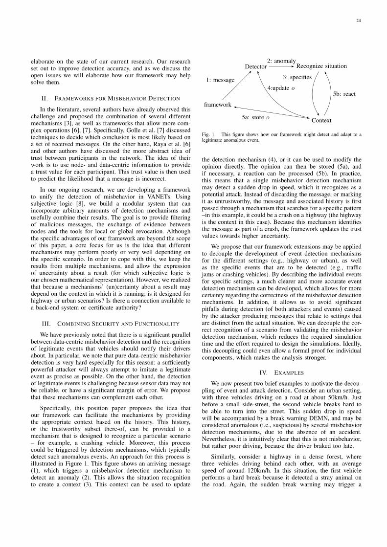
elaborate on the state of our current research. Our researchset out to improve detection accuracy, and as we discuss theopen issues we will elaborate how our framework may helpsolve them.
II. FRAMEWORKS FOR MISBEHAVIOR DETECTION
In the literature, several authors have already observed thischallenge and proposed the combination of several differentmechanisms [3], as well as frameworks that allow more com-plex operations [6], [7]. Specifically, Golle et al. [7] discussedtechniques to decide which conclusion is most likely based ona set of received messages. On the other hand, Raya et al. [6]and other authors have discussed the more abstract idea oftrust between participants in the network. The idea of theirwork is to use node- and data-centric information to providea trust value for each participant. This trust value is then usedto predict the likelihood that a message is incorrect.
In our ongoing research, we are developing a frameworkto unify the detection of misbehavior in VANETs. Usingsubjective logic [8], we build a modular system that canincorporate arbitrary amounts of detection mechanisms andusefully combine their results. The goal is to provide filteringof malicious messages, the exchange of evidence betweennodes and the tools for local or global revocation. Althoughthe specific advantages of our framework are beyond the scopeof this paper, a core focus for us is the idea that differentmechanisms may perform poorly or very well depending onthe specific scenario. In order to cope with this, we keep theresults from multiple mechanisms, and allow the expressionof uncertainty about a result (for which subjective logic isour chosen mathematical representation). However, we realizedthat because a mechanisms’ (un)certainty about a result maydepend on the context in which it is running; is it designed forhighway or urban scenarios? Is there a connection available toa back-end system or certificate authority?
III. COMBINING SECURITY AND FUNCTIONALITY
We have previously noted that there is a significant parallelbetween data-centric misbehavior detection and the recognitionof legitimate events that vehicles should notify their driversabout. In particular, we note that pure data-centric misbehaviordetection is very hard especially for this reason: a sufficientlypowerful attacker will always attempt to imitate a legitimateevent as precise as possible. On the other hand, the detectionof legitimate events is challenging because sensor data may notbe reliable, or have a significant margin of error. We proposethat these mechanisms can complement each other.
Specifically, this position paper proposes the idea thatour framework can facilitate the mechanisms by providingthe appropriate context based on the history. This history,or the trustworthy subset there-of, can be provided to amechanism that is designed to recognize a particular scenario– for example, a crashing vehicle. Moreover, this processcould be triggered by detection mechanisms, which typicallydetect such anomalous events. An approach for this process isillustrated in Figure 1. This figure shows an arriving message(1), which triggers a misbehavior detection mechanism todetect an anomaly (2). This allows the situation recognitionto create a context (3). This context can be used to update
framework
Detector
1: message
Recognize situation2: anomaly
Context
3: specifies
4:update o
5a: store o
5b: react
Fig. 1. This figure shows how our framework might detect and adapt to alegitimate anomalous event.
the detection mechanism (4), or it can be used to modify theopinion directly. The opinion can then be stored (5a), andif necessary, a reaction can be processed (5b). In practice,this means that a single misbehavior detection mechanismmay detect a sudden drop in speed, which it recognizes as apotential attack. Instead of discarding the message, or markingit as untrustworthy, the message and associated history is firstpassed through a mechanism that searches for a specific pattern–in this example, it could be a crash on a highway (the highwayis the context in this case). Because this mechanism identifiesthe message as part of a crash, the framework updates the trustvalues towards higher uncertainty.
We propose that our framework extensions may be appliedto decouple the development of event detection mechanismsfor the different settings (e.g., highway or urban), as wellas the specific events that are to be detected (e.g., trafficjams or crashing vehicles). By describing the individual eventsfor specific settings, a much clearer and more accurate eventdetection mechanism can be developed, which allows for morecertainty regarding the correctness of the misbehavior detectionmechanisms. In addition, it allows us to avoid significantpitfalls during detection (of both attackers and events) causedby the attacker producing messages that relate to settings thatare distinct from the actual situation. We can decouple the cor-rect recognition of a scenario from validating the misbehaviordetection mechanism, which reduces the required simulationtime and the effort required to design the simulations. Ideally,this decoupling could even allow a formal proof for individualcomponents, which makes the analysis stronger.
IV. EXAMPLES
We now present two brief examples to motivate the decou-pling of event and attack detection. Consider an urban setting,with three vehicles driving on a road at about 50km/h. Justbefore a small side-street, the second vehicle breaks hard tobe able to turn into the street. This sudden drop in speedwill be accompanied by a break warning DEMN, and may beconsidered anomalous (i.e., suspicious) by several misbehaviordetection mechanisms, due to the absence of an accident.Nevertheless, it is intuitively clear that this is not misbehavior,but rather poor driving, because the driver braked too late.
Similarly, consider a highway in a dense forest, wherethree vehicles driving behind each other, with an averagespeed of around 120km/h. In this situation, the first vehicleperforms a hard break because it detected a stray animal onthe road. Again, the sudden break warning may trigger a
24
misbehavior detection mechanism in the following vehicles todetect misbehavior, until they detect the animal.
In both cases, the context (the side street and the denseforest, respectively) provides an additional explanation forthe detected event that might otherwise have identified thesending vehicle as malicious. Similarly, attack detection maybe improved by this decoupling, as it allows the detection ofattacks that imitate the incorrect context. For example, when anattacker attempts to create a high-speed crash scenario basedon a highway setting in an urban one, we can detect that thesequence of messages does not match the twists and turns ofthe road. In addition, the approach simplifies the developmentof misbehavior detection mechanisms, because they no longerneed to provide a generic mechanism capturing all possiblescenarios, but rather can be designed to deal with specificscenarios.
V. CONCLUSION
In this position paper, we have proposed several ideason how to improve data-centric misbehavior detection inVANETs. We have briefly discussed existing work, includingapproaches that attempt to provide a framework for generalmisbehavior detection, and we have pointed out several openissues. We have then proposed several ideas that can be used toimprove data-centric misbehavior detection and its evaluation,which we hope provide the material for an exciting discussionof the topic during the Fachgesprach.
ACKNOWLEDGMENT
The authors would like to thank the participants of theprevious edition of the Fachgesprach Inter-vehicle Communi-cation for their insightful discussion and ideas, parts of whichhave inspired this work.
REFERENCES
[1] M. Raya and J.-P. Hubaux, “Securing vehicular adhoc networks,” Journal of Computer Security, vol. 15,no. 1, pp. 39–68, Jan. 2007. [Online]. Available:http://iospress.metapress.com/content/CH4D4DG8YL2QHR0W
[2] R. van der Heijden, S. Dietzel, and F. Kargl, “Misbehavior Detection inVehicular Ad-hoc Networks,” in 1st GI/ITG KuVS Fachgesprach Inter-Vehicle Communication (FG-IVC 2013), Innsbruck, Austria, February2013.
[3] T. Leinmuller, E. Schoch, F. Kargl, and C. Maihofer, “Decentralizedposition verification in geographic ad hoc routing,” Security andCommunication Networks, vol. 3, no. 4, pp. 289–302, Jul. 2010.[Online]. Available: http://doi.wiley.com/10.1002/sec.56
[4] W. Bamberger, J. Schlittenlacher, and K. Diepold, “A trust model forintervehicular communication based on belief theory,” in 2010 IEEESecond International Conference on Social Computing (SocialCom),2010, pp. 73–80.
[5] M. Ghosh, A. Varghese, A. Gupta, A. A. Kherani, and S. N. Muthaiah,“Detecting misbehaviors in VANET with integrated root-cause analysis,”Ad Hoc Networks, vol. 8, no. 7, pp. 778–790, Sep. 2010. [Online]. Avail-able: http://linkinghub.elsevier.com/retrieve/pii/S157087051000034X
[6] M. Raya, P. Papadimitratos, V. D. Gligor, and J.-P. Hubaux, “On data-centric trust establishment in ephemeral ad hoc networks,” in The27th Conference on Computer Communications IEEE INFOCOM 2008.IEEE, Apr. 2008, pp. 1238–1246.
[7] P. Golle, D. Greene, and J. Staddon, “Detecting and correcting maliciousdata in VANETs,” in Proceedings of the 1st ACM international workshopon Vehicular ad hoc networks, ser. VANET ’04. ACM, 2004, p. 2937.[Online]. Available: http://dl.acm.org/citation.cfm?id=1023881
[8] A. Jøsang, R. Hayward, and S. Pope, “Trust network analysis withsubjective logic,” in Proceedings of the 29th Australasian ComputerScience Conference - Volume 48, ser. ACSC ’06. Darlinghurst, Australia,Australia: Australian Computer Society, Inc., 2006, pp. 85–94. [Online].Available: http://dl.acm.org/citation.cfm?id=1151699.1151710
25

Identifying LTE Connectivity Hot Spots inVehicular Environments: A Learning Approach
Christoph Ide, Kai Piontek and Christian WietfeldCommunication Networks Institute
TU Dortmund University44227 Dortmund, Germany
e-mail: {Christoph.Ide, Kai.Piontek, Christian.Wietfeld}@tu-dortmund.de
Abstract—Due to the increasing demand of mobile Machine-Type Communications (MTC), the interaction between MTC andhuman services is a recent problem for cellular communicationsystems like Long Term Evolution (LTE). In order to reduce thenegative impact of MTC on human communication, a Learning-based Channel-Aware Transmission (L-CAT) scheme will beintroduced in this paper. The algorithm bases on a learningprocess of cellular connectivity hot spots and is designed for non-time-critical vehicular data applications like extended FloatingCar Data (xFCD) transmissions for traffic forecast systems. Theresults based on real-world measurements show that L-CAT leadsto a much faster data transmission that correlates with a moreresource efficient MTC.
I. INTRODUCTION AND RELATED WORK
Many mobile devices follow the routes of driving vehicles.This routes are not randomly, but follow special patterns. Forexample the same routes are taken by a vehicle many times: theway to work or to good friends. This fact can be used in orderto predict mobility of a cellular communication device that ismounted on a car. The mobility prediction is a feasible inputfor traffic management systems. It can be predicted how manyvehicles will pass a certain highway and if this would cause atraffic jam, some of them could be rerouted. But the mobilityestimation can also be useful for communication issues. In [1]a method to improve handover quality of cellular communi-cation systems by means of a mobility forecast algorithm isshown. However, the same routes correspond also to a similarcommunication connectivity. This fact will be used in thispaper to improve non-real-time vehicular data applications.We present Learning-based Channel-Aware Transmission (L-CAT), a decentralized communication approach that uses alearning process of cellular connectivity in vehicular environ-ments. L-CAT detects good communication locations, storesthem, provides them to others users and uses them for thenext drive at the same route to improve the communicationefficiency.
The transmission scheme can be used to provide vehicularsensor data (so called extended Floating Car Data (xFCD) [2])very efficiently to a traffic management server. This Machine-Type Communication (MTC), which can be carried e.g. bya Long Term Evolution (LTE) network, should interfere as
less as possible with other human users in the communicationnetwork. LTE MTC is a recent topic in the evolution ofthe standardization of LTE technology follower [3] [4]. Anoverview about vehicular LTE data communication can befound in [5].
The usage of the channel quality for efficient cellularcommunication is a common approach on different layers ofthe communication system. Channel-dependent scheduling [6](also for the uplink [7]) is one famous example for usingthe channel quality, aggregated at the base station of manyactive LTE users, to schedule the users to the best resources intime and frequency domain. In contrast to channel-dependentscheduling, L-CAT works on the application layer and decen-tralized without the need of an active communication link.In [8] a channel-aware transmission scheme is presented forrandom access networks. This scheme works without learningprocess and uses a threshold function for the transmission de-cision. A forecast algorithm for mobile connectivity in the areaof wireless and cellular communication systems is presented in[9]. The scheme takes active performance indicators (e.g. datarate) into account for the prediction of good communicationlocations for WiFi and cellular communication networks.
The key contributions of this paper are:
• The L-CAT scheme that uses a learning process of thecellular connectivity (cf. Sec. II).
• L-CAT implementation for the performance evaluation byreal world measurements (cf. Sec. III).
• L-CAT leads to a much faster data transmission due toa local transmission decision that is based on the LTEconnectivity (cf. Sec. IV).
• The faster data transmission is correlated with a moreresource efficient communication, so that L-CAT needsless physical resources for the same MTC payload size.
II. L-CAT CONCEPT
In [10], a channel-aware transmission scheme is proposedfor xFCD transmissions. The transmission policy is extendedby a learning component of the cellular connectivity in thispaper. Fig. 1 illustrates the L-CAT concept. The transmission
26

decision is done locally in the LTE device mounted on a ve-hicle. It depends on the data priority and cellular connectivity.The LTE connectivity estimation is based on two components,historical data and live measurements of passive indicators likeReference Signal Receive Power (RSRP) and Reference SignalReceived Quality (RSRQ). The historical data contains passiveas well as active connectivity indicators (e.g. local dependentdata rate) and the historical mobility. The live measurementsare only focused on passive performance indicators so thatno active connection to the cellular communication system isneeded before the transmission decision is done locally in theLTE device.
The cellular communication carries the xFCD in the uplinkas well as the traffic state and forecast from the traffic serverin the downlink. Connectivity maps that are generated by thedevices are also stored in the server. We suggest a bidirectionalupdate of the map in the vehicular and server via WiFi (e.g.ones in a week).
Traffic server
L-CAT: Local transmissiondecision dependent on- Data priority- Connectivity quality
LTE UE in vehicle
LTE eNodeB
Live, passive measurements- LTE RSRP and RSRQ- GPS position
Historical data- Passive LTE connectivity(RSRP and RSRQ map)
- Active LTE connectivity(data rate map)
- Mobility
LTE connectivity estimation
Traffic state andforecast information
xFCD
Bid
ire
ctio
na
l u
pd
ate
via
WiF
i
Fig. 1: Illustration of the L-CAT Concept.
III. IMPLEMENTATION OF L-CAT FOR LTE FIELD TESTS
This section summarizes the so far implemented function-alities of L-CAT. According to Fig. 1, we implemented afirst version in an Android app. The app contains four basiccomponents that are needed for L-CAT in the device:
• A look up map, where the historical connectivity mapis stored. In the app, local dependent connectivity issimplified by good connectivity hot spots. These areGlobal Positioning System (GPS) locations with a radiusthat describes regions with a very good connectivity (weuse RSRP > -90 dBm).
• A measurement function that monitors passively thecurrent LTE parameters.
• The LTE connectivity estimation is simplified in a func-tion that calculates the time until the next connectivity hotspot is reached by the current GPS position and velocity.
• The transmission decision in our app depends on goodconnectivity hot spots. We transmit a User DatagramProtocol (UDP) packet of 100 kByte if we are in such ahot spot or if we predict that the next hot spot is morethan five minutes away.
The measurements are performed in the public LTE networkof Deutsche Telekom. As performance indicator we measurethe transmission time. We will show in the result section thatthis indicator is strongly correlated with the number of LTEResource Blocks (RBs).
IV. RESULTS
For the performance analysis of L-CAT, we performed fieldtests in Dortmund, Germany. A map with measured LTE RSRPvalues of one example test drive is illustrated in Fig. 2. TheRSRP over time is shown in Fig. 3. On the one hand, thedriving route includes regions where no LTE coverage is given:e.g. at location B, a tunnel shadows the LTE signal. On theother hand, there are locations where the LTE signal qualityis very good. Nearby to position D, an LTE base station islocated. This results in RSRP values to up to -75 dBm.
The average RSRP is -99 dBm. This is also the averagevalue if no CAT is applied, which means that the data is trans-mitted periodically. By applying L-CAT, the average RSRP
RSRP [dBm]-120 -75-90-105
A
B
C
D
E
Fig. 2: Map of Example Measurement with RSRP Measure-ments. c© Google.
0 2 4 6 8 10 12 14 16 18 20 22-120
-110
-100
-90
-80
-70
Time [min]
RS
RP
[dB
m]
A
D
E
B C
No LTE coveragedue to tunnel
Very good LTE coveragedue to base station nerby
no CAT
CAT
Avergare RSRP:L-CAT
Fig. 3: RSRP over Time for one Example Measurement incl.RSRP Improvement due to CAT and L-CAT.
27

for triggering an LTE communication, increases to -85 dBm.This is due to the fact that locations D and E are identifiedas hot spots. For CAT, an average RSRP of -89 dBm can beachieved. The communication under better channel conditionsleads to a much faster data transmission. Fig. 4 illustratesthe transmission time of 100 kByte uplink data as box plots.These results are gained from a measurement campaign of2 h duration. It can be seen from the figure that a very widerange of transmission times is given for a transmission withoutCAT. The very high values result from LTE communicationsat location A or between D and E, where the connectivity isvery bad. For CAT, the average transmission time decreases to540 ms in contrast to 720 ms for a periodical transmission. Thefact that many transmissions are also very fast (< 1 s) withoutCAT is caused by the good LTE coverage in the surroundingsof location D. By applying L-CAT, the average transmissiontime can be deceased to 430 ms. Furthermore, peaks with avery high transmission time can be avoided by the usage ofthese hot spots. In our measurement campaign, the maximumtransmission time with L-CAT is 730 ms. These results showthat the LTE connectivity based on a passive indicator (weuse the RSRP) recorded in previous measurements can beused in order to optimize an active LTE communication inthe presence.
We have shown in [11] that the same LTE deploymentprovides a scheduler that is similar to a max rate scheduling forsmall packets. This means that users with a very low RSRPvalue are assigned less RBs in the frequency domain thanusers with good channel conditions. This leads to the factthat for a low RSRP, the duration of the transmission is notonly longer because more total resource are necessary (dueto a more robust modulation and coding and retransmissions),but also because the resources in the frequency domain arerestricted. However, there is still a strong correlation betweentransmission time and total number of RBs given. This rela-tionship is shown in Fig. 4. These LTE field measurements aregained with the same setup used in [11]. By means of a real-time spectrum analyzer, the RBs in time and frequency domainare captured at seven different locations with various channelconditions. The correlation coefficient between transmissiontime and total number of RBs is 0.82.
V. CONCLUSION AND FUTURE WORK
In this paper, we have presented L-CAT, a decentralizedtransmission protocol for vehicular data applications. Thetransmission decision is based on a learning process of thecellular communication connectivity. The performance of L-CAT is analyzed by real-world measurements. It is shown thatthe communication policy leads to a much faster vehiculardata transmission that is correlated with a much higher LTEresource efficiency. In the future, we will validate the L-CATscheme by protocol simulations and extent the transmissiondecision by taken application characteristics into account. In
0
1
2
3
4
Tra
nsm
issio
n tim
e [s]
w/o CAT CAT L-CAT
0 400 800 12000
1
2
3 x 10⁴
Time [ms]
Tota
l num
ber
of R
Bs
Linear fit
Fig. 4: Comparison of the Transmission Time for without CAT,CAT and L-CAT as well as Correlation between TransmissionTime and Total Resource Allocation (100 kByte).
addition, we will develop more complex forecasting algorithmsin order to predict the mobility in challenging scenarios.
ACKNOWLEDGMENT
Part of the work on this paper has been supported byDeutsche Forschungsgemeinschaft (DFG) within the Collab-orative Research Center SFB 876 “Providing Informationby Resource-Constrained Analysis”, project B4. The authorswould like to thank Stephan Frieling for implementing the app.
REFERENCES
[1] S. Michaelis and C. Wietfeld, Comparison of User Mobility PatternPrediction Algorithms to Increase Handover Trigger Accuracy, The 63rdIEEE Vehicular Technology Conference 2006, Melbourne, Australia,May 2006.
[2] M. L. W. Huber and R. Ogger, Extended Floating-Car Data forthe Acquisition of Traffic Information, World Congress on IntelligentTransport System, Toronto, Canada, 1999.
[3] 3GPP TR 23.888 V11.0.0, System Improvements for Machine-TypeCommunications, Sep. 2012.
[4] 3GPP TS 22.368 V12.2.0, Service Requirements for Machine-TypeCommunications, Mar. 2013.
[5] G. Araniti et al., LTE for Vehicular Networking: A Survey, IEEECommunications Magazine, vol. 51, no. 5, May. 2013.
[6] J. Jang and K. B. Lee, Transmit Power Adaptation for Multiuser OFDMSystems, IEEE J. Sel. Areas Commun., vol. 21, pp. 171-178, Feb. 2003.
[7] J. Lim et al, Channel-Dependent Scheduling of Uplink Single CarrierFDMA Systems, IEEE 64th Vehicular Technology Conference (VTC-Fall), Montreal, Canada, Sep. 2006.
[8] S.-H. Wang, A.-D. Lin and Y.-W. P. Hong, Channel-Aware TransmissionControl for Cooperative Random Access Networks, IEEE 76th VehicularTechnology Conference (VTC-Spring), Taipei, Taiwan, May. 2010.
[9] A. J. Nicholson and B. D. Noble, BreadCrumbs: Forecasting MobileConnectivity, ACM International Conference on Mobile Computing andNetworking, San Francisco, USA, Sep. 2008.
[10] C. Ide, B. Dusza, M. Putzke and C. Wietfeld, Channel SensitiveTransmission Scheme for V2I-based Floating Car Data Collection viaLTE, IEEE International Conference on Communications (ICC), Ottawa,Canada, Jun. 2012.
[11] C. Ide et al., Performance of Channel-Aware M2M Communicationsbased on LTE Network Measurements, 24th IEEE International Sympo-sium on Personal, Indoor and Mobile Radio Communications (PIMRC),London, UK, Sep. 2013.
28
Real World Privacy Expectations in VANETs
Michael FeiriServices, Cybersecurity and Safety
University of TwenteThe Netherlands
Email: [email protected]
Jonathan PetitServices, Cybersecurity and Safety
University of TwenteThe Netherlands
Email: [email protected]
Frank KarglInstitute of Distributed Systems
University of UlmUlm, Germany
Email: [email protected]
Abstract—Vehicular communication technology is nearing de-ployment in the market. We see initial plug tests in 2013 to con-firm interoperability of multiple independent implementations.As the entrance into the market is coming closer it is time toconsider the privacy expectations of the relevant standards. Theseexpectations are built upon location privacy through unlinkablepseudonyms. In this paper we focus on the real world privacyexpectations that can be fulfilled in the first generation ofvehicular communication technology using pseudonymity. Whatlevel of privacy is really achievable and does the effort to achievethis level privacy justify the cost and complexity of introducingpseudonymity into vehicular communication?
I. INTRODUCTION AND RELATED WORK
Privacy for passengers of cooperative vehicles was iden-tified as a requirement for market acceptance quite earlyin the process of developing vehicular communication in-frastructure. The SEcure VEhicular COMmunication project(SeVeCom) [1] collected relevant attacker scenarios and pro-posed pseudonyms as a useful approach to provide privacyin vehicular contexts. The use of pseudonyms does not implyanonymity, because short-term identities are still attached tovehicles to ensure accountability and non-repudiation. Thekey requirement for the effectiveness of pseudonyms is theirunlinkability for attackers, while authorities may have theability to resolve pseudonymous identities to the owner of avehicle.
Major standardization efforts for vehicular communicationsystems at ETSI [2] and IEEE [3] consider pseudonymity intheir security architectures. However, important details remainunderspecified and subject to research. The biggest openquestion concerns the strategy for pseudonym changes, whichhas a large influence on the effectiveness of pseudonyms.Previous research efforts have already highlighted challengesof performing effective pseudonym changes. According tothese efforts it requires drastic measures, such as silent pe-riods [4], [5] or context sensitive collaborative operations inmix-zones [6], [7] to ensure meaningful k-anonymity. Onlyrecently have researchers started to investigate the impact ofpseudonym change strategies on service quality [8]. Never-theless the full consequences and practicability of pseudonymchange strategies in realistic environments are still not wellunderstood.
The implications of these issues raise concerns aboutthe practicability of meaningful privacy guarantees throughpseudonym changes. Is effective location privacy attainablewithout severe penalties for service quality? Is it attainable if asignificant amount of collaborative vehicles is simply unwilling
or unable to participate in adequate pseudonym change proto-cols? What kind of attacker can pseudonym change protocolseven protect against?
II. ASSUMPTIONS AND ATTACKER MODELS
A. Service quality assumptions
The potential for Sybil attacks has been identified inprevious works related to security and privacy in vehicular net-works [9], [10], which is a reason to strictly limit the validity ofpseudonymous certificates. Recommendations for deploymentsof pseudonymous certificates suggest lifetimes of around fiveminutes [11]. However such configurations would preventpseudonym change strategies that rely on unpredictable contextsensitive and/or collaborative pseudonym change strategies.Any unpredictable pseudonym change strategy requires theavailability of multiple valid pseudonyms. Proof-of-work sys-tems might counter simple sybil attack scenarios, thoughfundamentally the risk of sybil attacks remains.
Recent research by Lefevre and Petit [8] has highlighted thesevere impact of silent periods [4], [5] as part of a pseudonymchange strategy on service quality of Intersection CollisionAvoidance (ICA) applications. This observation is unlikelyto be limited to ICA applications. Cooperative awareness isthe fundamental building block of many safety applicationsin vehicular networks, such as ICA. An unfortunately timedpseudonym change could break the stability of cooperativeawareness. The basic position beacons that all vehicles areexpected to broadcast to announce their position and trajectoryare sometimes even called Cooperative Awareness Messages(CAM) [12]. These are mandatory messages and the awarenessof the exact position of surrounding vehicles is a key enablerfor most safety applications. The need for awareness of sur-rounding entities is a fundamental requirement. Privacy preser-vation efforts must not interfere with this requirement. If a fullyanonymous communication protocol was available, it wouldnot be an applicable solution for vehicular communicationnetworks. This is because it would make entities untrackableeven in close proximity, thus breaking the correctness of theawareness of surrounding vehicles. Local trackability is thefoundation of cooperative safety.
As pointed out by Lefevre and Petit [8], if pseudonymchanges include long silent periods, it would become untenableto build services that provide safety critical services. It appearsreasonable to only allow silent periods in situations withoutany safety relevant interactions with other vehicles. However,it is not predictable if and how frequently such situations
29

will occur. Furthermore due to hidden station effects even thedetection of such situations is unlikely to be reliable enough forconsideration in combination with safety critical applications.
Mix Zones [6] have been proposed as a way to collabo-ratively perform pseudonym changes. This technique can givea reasonable amount of expected k-anonymity even under theassumption that an attacker can observe the entire pseudonymchange process. The Mix Zones concept achieves a consid-erable effectiveness in this scenario, however the attacker isconsidered to be a passive observer. The synchronization ofpseudonym changes with other entities implies that privacydecisions depend on external input. Unavailability, inability oreven malicious unwillingness to participate in a pseudonymchange process might prevent vehicles from ever changingtheir pseudonyms. Additionally the adherence to as combinedsilent period would be problematic for the above mentionedreasons. This also applies to encrypting messages insteadof stopping to send messages, as proposed by Freudiger(CMIX) [7]. The potential inability of nearby vehicles toprocess messages would have a similarly negative effect onservice quality, while high resolution tracking would still allowfor tracking of even encrypted beacons.
B. Attacker models
The natural upper bound for an attacker is an all seeingobserver with the ability to perform active attacks. A combina-tion of mix zones and silent periods could thwart an all seeingpassive attacker, but as discussed previously, silent periods andreliance on cooperative pseudonym change protocols may notbe realistic options in practice. A study about the effectivenessof an all seeing attacker using Multi Hypothesis Tracking(MHT) was performed by Wiedersheim et.al. [13] and showshigh levels of success for the attacker, even under noisy dataand extremely frequent pseudonym changes. We are not awareof effective countermeasures against an all seeing passive oractive observer under realistic service quality requirements.
Even with gaps in the coverage of the attacker it is highlylikely that an attacker can simply watch and match vehiclesacross pseudonym changes. Advanced tracking algorithms arevery effective at tracking and predicting vehicle mobility.A set of studies examining plausibility checks of locationclaims reveals high success rates of vehicle tracking usingKalman filters [14], [15] and Particle filters [16]. Such localtracking of nearby vehicles also reveals an interesting lowerbound on attacker capabilities. There is no effective way ofdefending location privacy against a single mobile attacker,which simply follows a vehicle. Such following can be basedon the position beacons or alternatively on sensor readingsthat work in close proximity to the surveilled vehicle. Themobile attacker can then watch the surveilled vehicle, triviallyobserving and linking any pseudonym change in the vehicularcommunication channel.
III. FUTURE WORK
We see that the pseudonym changes are ineffective againstpowerful all seeing observers and ineffective against small butmobile observers. The protection level against medium sizedattackers is subject to further research. It is likely dependenton attacker mobility and the coverage of the relevant area.
Covering for example intersections and considering knowledgeof pseudonym change strategies should enable very effec-tive tracking. Reliably privacy protection within the existingpseudonymity framework is only provided against small im-mobile attackers. We see that that pseudonym changes underrealistic assumptions can only protect effectively against thiskind of weak attacker. It becomes reasonable to wonder ifpseudonym changes at the beginning and at the end of a tripmight suffice.
Ultimately, it might be worth questioning if the cost and thecomplexity of implementing pseudonymous communication isjustified by the limited level of attainable privacy. It mightalso be worth considering whether the concealment of vehicleidentification is necessary to protect the privacy of passengers.Car sharing models might make it questionable to directlylink vehicle ownership to the identity of the human driver.Moreover, what if an autonomous vehicle does not even carrya passenger? Meanwhile, passengers do expect privacy in thesense of being anonymous, while pseudonym change strategiescan only offer unlinkability against small and medium sizedimmobile attackers.
REFERENCES
[1] P. Papadimitratos, A. Kung, J.-P. Hubaux, and F. Kargl, “Privacy andidentity management for vehicular communication systems: A positionpaper,” in Workshop on Standards for Privacy in User-Centric IdentityManagement, Zurich, Switzerland, July 2006.
[2] ETSI TC ITS, “ETSI TS 102 731 v1.1.1 - intelligent transport systems(ITS); security; security services and architecture,” Standard, TC ITS,2010.
[3] IEEE, “IEEE 1609.2v2 - Standard for Wireless Access in VehicularEnvironments (WAVE) - Security Services for Applications and Man-agement Messages,” 2011.
[4] K. Sampigethaya, L. Huang, M. Li, R. Poovendran, K. Matsuura, andK. Sezaki, “CARAVAN: Providing location privacy for VANET,” in 3rdWorkshop on Embedded Security in Cars (ESCAR ’05), 2005, pp. 1–15.
[5] L. Huang, H. Yamane, K. Matsuura, and K. Sezaki, “Towards mod-eling wireless location privacy,” in Privacy Enhancing Technologies.Springer, 2006, pp. 59–77.
[6] A. Beresford and F. Stajano, “Location privacy in pervasive computing,”Pervasive Computing, IEEE, vol. 2, no. 1, pp. 46–55, 2003.
[7] J. Freudiger, M. Raya, M. Felegyhazi, P. Papadimitratos et al., “Mix-zones for location privacy in vehicular networks,” in Proceedings ofthe first international workshop on wireless networking for intelligenttransportation systems (Win-ITS), 2007.
[8] S. Lefevre, J. Petit, R. Bajcsy, C. Laugier, and F. Kargl, “Impact of v2xprivacy strategies on intersection collision avoidance systems,” in IEEEVehicular Networking Conference, 2013.
[9] T. Zhou, R. R. Choudhury, P. Ning, and K. Chakrabarty, “Privacy-preserving detection of sybil attacks in vehicular ad hoc networks,”in Mobile and Ubiquitous Systems: Networking & Services, 2007.MobiQuitous 2007. Fourth Annual International Conference on. IEEE,2007, pp. 1–8.
[10] F. Schaub, Z. Ma, and F. Kargl, “Privacy requirements in vehicularcommunication systems,” in Computational Science and Engineering,2009. CSE’09. International Conference on, vol. 3. IEEE, 2009, pp.139–145.
[11] ETSI TC ITS, “ETSI TS 102 867 v1.1.1 - intelligent transport systems(ITS); security; stage 3 mapping for ieee 1609.2,” Standard, TC ITS,2012.
[12] ETSI, “Intelligent transport systems (ITS); vehicular communications;basic set of applications; part 2: Specification of cooperative awarenessbasic service,” EN 302 637-2.
30

[13] B. Wiedersheim, Z. Ma, F. Kargl, and P. Papadimitratos, “Privacyin inter-vehicular networks: Why simple pseudonym change is notenough,” in 7th International Conference Wireless On-demand NetworkSystems and Services (WONS ’10), 2010, pp. 176–183.
[14] H. Stubing, A. Jaeger, C. Schmidt, and S. A. Huss, “Verifying mobilitydata under privacy considerations in car-to-x communication,” in 17thITS World Congress, 2010.
[15] A. Jaeger, N. Bimeyer, H. Stbing, and S. Huss, “A novel frameworkfor efficient mobility data verification in vehicular ad-hoc networks,”International Journal of Intelligent Transportation Systems Research,vol. 10, no. 1, pp. 11–21, 2012.
[16] N. Bismeyer, S. Mauthofer, K. Bayarou, and F. Kargl, “Assessmentof node trustworthiness in vanets using data plausibility checks withparticle filters,” in Vehicular Networking Conference (VNC), 2012 IEEE,2012, pp. 78–85.
31
Implementation of Day One ITS-G5 Systemsfor Testing Purposes
Raphael RieblTechnische Hochschule Ingolstadt
Research CentreEmail: [email protected]
Christian FacchiTechnische Hochschule Ingolstadt
Research CentreEmail: [email protected]
Abstract—As the finalisation of several components of the Intel-ligent Transport System (ITS) network stack for communicationin the 5.9 GHz spectrum (ITS-G5) is taking shape, it is abouttime to evaluate the performance of the European Inter-VehicleCommunication (IVC) communication variant as backed by theCAR 2 CAR Communication Consortium (C2C-CC) as a whole.In order to evaluate the performance of ITS-G5 stations, it isuseful to study the interaction of the involved network layers.In this paper, progress made towards an ITS-G5 implementationcapable to be used in embedded and simulation environments ispresented.
I. INTRODUCTION
After several years of design and research in IVC some notyet finalised standards are now expected to get approved soon.For example, the GeoNetworking (GN) specification [1] is atthe time of writing in the final approval procedure. Some otherstandards as the p amendment to IEEE 802.11, also knownas pWLAN for short, are established for years already. Inthe context of this paper an IVC system is a network stackaccording to recent ETSI ITS specifications and configured asdescribed by the C2C-CC Basic System Standards Profile [2].
While a few hundred milliseconds latency might not becritical for informational services, it can be fatal for safety-critical services, if data is not disseminated within a short timeframe, depending on the particular use case. For that reason, itis necessary to assure, that the designed communication systemas well as a particular implementation is capable to satisfysuch time frames even under stressful conditions. As has beenshown in [3], there arise problems like oscillating DistributedCongestion Control (DCC) states when channel load is justincreased enough. Therefore, it is promising to investigate ifit is still possible to maintain low-latency requirements forsafety-critical messages.
Taking these considerations into account, testing of pWLANbased Vehicular Ad Hoc Networks (VANETs) should be possi-ble in a cost-efficient, reliable and replicable manner. Further-more, a testing setup shall be able to handle scenarios witha lot of vehicles and therefore a crowded radio channel, soa network stack’s behaviour can be studied with suboptimalcommunication premises.
Though large-scale field tests have been conducted in thepast [4], these tend to be expensive and it is hard to repeatthose. As the system evolves, tests have to be carried outagain though. An appropriate way out of this dilemma are
simulations. In the following, an extended version of theVeins framework 2.1 [5] is presented. Veins already supportsthe coupling of network communication and realistic vehiclemobility simulation, which are the fundamental aspects of IVC.The extension covers an complete ITS-G5 stack and enablesthe integration of real communication devices. Since there arealready experts working on measurements of the radio signalitself, e.g. as part of ETSI ITS Plugtests in November 2013,the following simulation-based test setup focuses on protocolinteractions from access layer upwards, but not on physicalradio propagation phenomena like multipath, reflections etcetera. Instead, a simplified model supplied with Veins [6] isused to determine if vehicles are within communication range.
Simulations have already been conducted for various aspectsof VANETs, which are either limited to certain layers orsingle use cases though. Since the simulations presented in[3] are also utilising the Veins framework, they are similarto those designated in this paper. However, they had a focuson the physical and access layer. Other aspects like multi-hoptransport types and its implications are not considered.
II. DESIGN
One problem inherent to simulations is to make sure,that the simulation model and its assumptions match realworld conditions appropriately. This issue is approached in thefollowing with the conception of an ETSI ITS-G5 compliantstack named Vanetza, which is intended to be usable for eventdiscrete simulations like Veins and is nonetheless executableon embedded systems. It can be handy to run the networkstack on a real device for testing the interoperability with otherimplementations and thereby validate the simulation model, atleast partly. Furthermore, an outline is given of a possibility totest a Device Under Test (DUT) with channel load generatedby a simulated environment, as it is sketched in Figure 1. Forthis purpose a DUT can interact with the simulation over itsradio interface. The radio interface is chosen, because it iscommon for all ITS-G5 devices and all layers of the DUT areincluded in this way.
As a guideline for the features required to implement forDay One usage as propagated by the C2C-CC, refer to itsBasic System Standards Profile [2] and the accompanyingdocument concerning DCC [7].
32

A. Simulation
Simulations enable investigation of scenarios with po-tentially lots of participating vehicles. Veins [6] employsOMNeT++ [8] for the simulation of network communicationand SUMO [9] for vehicle mobility. Since OMNeT++ is basedon the concept of discrete event simulation, time progress iscontrolled by an event scheduler maintaining an event list.Therefore, the network stack’s awareness of time progress iscaused by increasing time stamps provided by the simulation.In order to handle timeouts internal to the network stack, e.g.the BEACON timer of GN [1] or expiration of location tableentries, the network stack can propose the next invocationtime stamp. Hence an appropriate event can be scheduled.Furthermore, the Vanetza network stack has to be capable toget instantiated multiple times in the same simulation systemprocess. This is not achievable with the proprietary networkstack implementations known to us.
B. Embedded System
For demonstration of the Vanetza communication stack onembedded systems, the well-known MK2 of Cohda Wireless1
is deployed. This device allows injection and interception ofcustom packets at the Medium Access (MAC) layer through araw packet socket Application Programming Interface (API).Since there are only constrained hardware resources availableon embedded systems like the MK2, it is mandatory to keepresource usage by the network stack low. In addition, thisrequirement holds true for powerful machines where the simu-lation is executed, because these have to run possibly hundredsof network stack instances in parallel. Events from outside, i.e.data indications from the MAC layer or data requests from theapplication layer, are handled quite similar to the simulationmode. Occurrence and order of these events, however, is notscheduled in advance but caused by environmental stimuli. Incontrast to the simulation mode, there is an additional timercomponent in embedded systems mode, which triggers theinternal events of the network stack.
The MAC layer is accessed in both cases through a light-weight interface which unifies the network stack’s communi-cation to the simulated MAC interface in Veins and the rawpacket socket on Cohda’s MK2 device.
C. Combination of Simulation and Embedded System
Beside purely simulative or embedded use cases, a hybridapproach is useful for testing devices. Therefore, bridging thegap between both worlds by coupling simulation and a DUTis beneficial.
Figure 1 gives a conceptional overview of a simulationarchitecture, which integrates a real ITS-G5 device, so itcan interact with the simulation. In the simulation a singlevehicle is selected, which shall represent the Ego vehicle.It represents movement and communication behaviour of thereal hardware DUT in the simulated world. This simulatedvehicle is special, because its upper network stack is not
1http://www.cohdawireless.com/product/mk2.html
„traffic & mobility”
OMNeT++
Simulation: Veins + extensions
proxy
DUT
Messages
Ego-GPS positions
Scenario: map, vehicles, routes…
pWLAN
„Ego”Messages
invisible to Ego
„communication”
SUMO
from & to Ego
Fig. 1. Simulation architecture
part of the simulation, but executed on the DUT . When theEgo vehicle’s simulated MAC layer receives a packet from itsvirtual environment, this packet is relayed to DUT througha component called pWLAN proxy. This pWLAN proxy isa MK2 device with a custom application connected to thesimulation over Ethernet. At the same time pWLAN proxyand DUT are able to communicate over the air. However, notall packets sent by simulated vehicles are relayed. Only thosepackets with a signal strength above a predefined thresholdare forwarded to the proxy. Signal strength degrades withincreasing distance of signal path and number of obstaclesalong this path, as presented in [6]. The other way roundpackets emitted by the DUT are captured by the proxy andinjected in the simulation and virtually transmitted to Egovehicle’s neighbours. There is also a data stream of GlobalPositioning System (GPS) positions going from the simulationto DUT , which allows us to fake GPS positions for the networkstack running on DUT .
Since the simulation has to react on external stimuli,the event scheduler of the event discrete simulation toolOMNeT++ used by Veins has to be replaced with a customimplementation. While the default scheduler tries to makeprogress as fast as possible, i.e. the simulated time is notbound to wall clock time, the customized scheduler namedProxyScheduler tries to keep simulated and wall clock timesynchronized. In Figure 2 an example of ProxyScheduler’sbehaviour is depicted as sequence chart. Instead of continuingwith the following event immediately as the default schedulerdoes, ProxyScheduler listens for messages from outsideuntil the wall clock time catches up. If a message is receivedin the meantime, a new simulation event is generated andput into OMNeT++’s event data structure cMessageHeap
appropriately. The communication connection to the outsideenvironment is provided through the CohdaProxy, whichincorporates the data exchange between simulation and proxy.Of course, this mechanism works only as long as the computeris able to process simulation events faster then the wall clocktime progresses. If there are too many simulated vehicles, thisis no longer the case. A speedup in simulation execution mightbe achievable through parallelization though. At the momentall events are processed in strict sequential order.
In order to keep hardware costs low, a single MK2 devicehas to handle the packets of several simulated vehicles. Thus
33

getNextEvent()
: ProxyScheduler : cMessageHeap : CohdaProxy
peekFirst()
nextEvent
determineTimeoutValue(nextEvent)
receive(timeout)
packetData
createProxyMessage(packetData)
insert(proxyMessage)proxyMessage
Fig. 2. Scheduling of a simulation event due to an incoming DUT packet
latency experiments were conducted to see if such a deviceis capable to do so. The measurement series in Figure 3shows the round-trip-time for a packet with 500 bytes of MACpayload sent by one MK2 (ping) and returned by another(echo). A lot of round-trip-times are located around 4.9, 6.0and 6.5 ms. Interestingly, there are also repeated peeks upto 10 ms with uniform intervals. Since there is no increasein packet loss at the same time, this is possibly causedby a temporarily increased processor load, e.g. a periodickernel task delaying packet processing slightly. Channel loadis controlled through an artificial pause of 2 ms between twopings, whereas echoes are replied as fast as possible. Reducingthe pause by 1 ms caused an immense increase of measuredround-trip-time. Increasing the pause, however, did not affectthe reliability of the transmission significantly. A 2 ms pausemeans 500 messages per second just sent by one MK2 andthe double number of messages occupying the channel in thesame time. Because of size constraints, presentation of furtherresults for other packet lengths and timings are omitted. Ifchannel load regulations are considered as enforced by DCC[7], which restricts the average maximum message rate inrelaxed state to less than 20 messages per second per station,the load of at least 25 neighbour stations could be representedwith one MK2 device. Consequently, it is possible to reducethe number of required communication devices significantly.
III. IMPLEMENTATION
For the basic services, namely the Physical (PHY) and MAClayers of IEEE 802.11p, it is possible to rely on alreadyavailable implementations. Since the interfaces provided byVeins’ implementation of these layers were too limited to acertain use case, some minor customisations were necessaryto make them more generic.
In the following, some implementation decisions are high-lighted and explained, how these simplify reasoning aboutspecifications. For demonstration purposes the GN layer asspecified in [1] is used. The motivation to employ C++
0 200 400 600 800 1,000
4
6
8
10
Pings
Rou
nd-t
rip-
time[m
s]
measurement 1measurement 2measurement 3
Fig. 3. Latencies for 2 ms intervals and 500 bytes payload
for the network stack implementation stems from the desireof reasonable performance and easy interaction with APIswritten in C like the Cohda Software Development Kit (SDK).Furthermore, simulation tools like OMNeT++ are written inC++ too.
To simplify reasoning about the specification the sourcecode should be kept as close to the specification language aspossible. Consequently, maintenance code should be kept at abare minimum, i.e. it is unfavourable to clutter code alignedto the specification text with memory management and low-level maintenance of data structures. Instead, it is favourableto have compact and expressive code.
A. Byte order
Though byte order is not a new difficulty, it can still causesome headaches. If a field in GN headers consists of multiplebytes, it has to be transmitted in big endian byte order [1,p. 12]. The host byte order of e.g. x86 processors, however, islitte endian. There are a number of C functions for swappingbytes, but there is no way to distinguish which kind of order ispresent in a particular variable. Developers have to rememberthe used byte order, which causes subtle errors when valueswith different byte orders are mixed carelessly. Since it issyntactically valid code, the compiler will not produce anywarnings though. In Linux kernel development a dedicatedtool is used for detection of semantic errors as e.g. illegalassignment of little endian values to big endian variables andvice versa [10]. This, however, requires an additional stepduring the build process. Vanetza’s way to deal with byteorder, however, is based on C++’s type system and thereforeenforced by the C++ compiler. Types as e.g. uint16le_tand uint16be_t are distinct types based on standard C++’suint16_t type with the associated byte order encoded aspart of the type information. Sequence numbers within GNheaders for example are of type uint16be_t and thus stored
34
in big endian order, whereas for arithmetic manipulation inprogram logic they are available in host byte order. At runtimethese custom types just occupy as much memory as theirunderlying type. Through byte swapping they can be convertedinto each other seamlessly while retaining appropriate byteorder information. The accompanying byte swapping functionsare left out if two variables’ byte order matches already andresult in no performance loss at runtime. In the end, thedescribed approach helped to get rid of byte order confusionsand hence data fields transmitted in wrong byte order.
B. Encoding of Quantities
Quantities, consisting of a magnitude and a unit, are en-coded in various ways in GN header fields. For example,heading values have a precision of 1/10 degree in Long PositionVectors whereas the angle in a GeoBroadcast (GBC) headerhas a precision of 1 degree. Thus, a value of 10 has to beinterpreted as 1 degree and 10 degree respectively, though bothfields are of 16 bit unsigned integer type. It might also befavourable to use another unit internally, because the C/C++math library expects angle values in radian measure insteadof angular degree. Fortunately, there is already a librarycalled Boost.Units available [11], which allows to enrichscalar types like double with unit information and evenprovides dimensional analysis at compile time. Based on thislibrary, special types for header field quantities can be built,which relieve developers from the burden to remember thecurrently involved scaled unit and convert appropriately. Withthe introduction of these types it was possible to track downseveral implementation errors. Without these types carefulsource code analysis and time-consuming debugging wouldhave been necessary. Furthermore, there is now a lower risk tointroduce bugs during source code changes, e.g. due to missingscaling of values.
IV. CONCLUSION
During the implementation of the GN layer, some unsoundparts were discovered and reported to our project partner andafter internal review to ETSI for further discussion. As oneexample, an unnecessary delay when a source station is goingto send a GBC message utilising Contention Based Forwarding(CBF) [1, Annex E.3] has been found. While for forwarderoperation the CBF timers are essential, they are meaninglessfor source operation because the message originates fromsource station. In the worst case this introduces a delay of100 ms, the maximum duration of a packet in the CBF buffer.This reduces the total time available for a receiving vehicle toreact on a possibly safety-critical message.
Another example concerns the buffering of GBC packets.Since the CBF algorithm might execute the greedy forwardingalgorithm, a GBC packet might be buffered in a unicast bufferby greedy forwarding. Consequently, the intended behaviourof the GN layer is unclear at this point. In this case a proposalhas been made to buffer it in the semantically correct broadcastbuffer and re-execute the forwarding algorithm which causedthe buffering in first place when flushing the buffer later on.
As the presented implementation has not yet been finished,possibly more feedback can be given soon for eliminationof remaining glitches, so a reference system as envisagedby C2C-CC can be built with less effort. Furthermore, theauthors are looking forward to simulate large scenarios withC2C-CC Day One compliant communication stacks as soonas all Day One features are covered. When the network stackrunning on an embedded system is adjudged to be conformantto the specification, it can be concluded due to the commoncode base, that its simulation counter-part is most probablyconformant as well. This increases the confidence into futuresimulation results.
ACKNOWLEDGEMENT
The authors would like to thank the AUDI AG for support-ing their research on this topic.
REFERENCES
[1] European Telecommunications Standards Institute,Draft ETSI EN 302 636-4-1, 1.2.0, Oct. 2013.
[2] B. van der Kluit, T. Buburuzan, et al., C2C-CC BasicSystem Standards Profile, 1.0, 2013.
[3] D. Eckhoff, N. Sofra, and R. German, “A PerformanceStudy of Cooperative Awareness in ETSI ITS G5 andIEEE WAVE,” in Wireless On-demand Network Systemsand Services (WONS), 10th Annual Conference on,2013, pp. 196–200.
[4] simTD Konsortium, simTD | fakten, Jun. 2013. [Online].Available: http://www.simtd.org.
[5] C. Sommer, R. German, and F. Dressler, “Bidirection-ally Coupled Network and Road Traffic Simulation forImproved IVC Analysis,” IEEE Transactions on MobileComputing, vol. 10, no. 1, pp. 3–15, 2011.
[6] C. Sommer, D. Eckhoff, R. German, and F. Dressler, “AComputationally Inexpensive Empirical Model of IEEE802.11p Radio Shadowing in Urban Environments,” inWireless On-Demand Network Systems and Services,Eighth International Conference on, 2011, pp. 84–90.
[7] J. Rey, N. Sofra, and K. Sjöberg, C2C-CC DistributedCongestion Control (DCC) for Day One, 1.0, 2013.
[8] A. Varga and R. Hornig, “An overview of theOMNeT++ simulation environment,” in Proceedings ofthe 1st international conference on Simulation tools andtechniques for communications, networks and systems& workshops, 2008, pp. 1–10.
[9] D. Krajzewicz, J. Erdmann, M. Behrisch, and L. Bieker,“Recent Development and Applications of SUMO -Simulation of Urban MObility,” International JournalOn Advances in Systems and Measurements, vol. 5, no.3&4, pp. 128–138, Dec. 2012.
[10] L. Torvalds, P. Machek, and B. Copeland, sparse,Oct. 17, 2013. [Online]. Available: https:/ /git .kernel .org / cgit / linux / kernel / git / torvalds / linux . git / tree /Documentation/sparse.txt?id=refs/tags/v3.10.
[11] M. C. Schabel and S. Watanabe, Boost.Units 1.1.0,Boost 1.55.0, Nov. 2013.
35

A Modular Approach to Platooning ManeuversMichele Segata∗†, Falko Dressler∗, Renato Lo Cigno†
∗Computer and Communication Systems, Institute of Computer Science, University of Innsbruck, Austria†Department of Information Engineering and Computer Science, University of Trento, Italy
{segata,dressler}@ccs-labs.org, [email protected]
Abstract—Driving vehicles in platoons has the potential toimprove traffic efficiency, increase safety, reduce fuel consump-tion, and make driving experience more enjoyable. A lot ofeffort is being spent in the development of technologies, likeradars, enabling automated cruise control following and ensuringemergency braking if the driver does not react in time; butthese technologies alone do not empower real platooning. Asplatoons will initially share the road with human-driven vehicles,interesting new questions regarding the interactions between thetwo categories of vehicles arise. In this paper we briefly describethe focus of our research, i.e., the analysis of interferences causedby non-automated vehicles during a maneuver. As an example,we consider the JOIN maneuver. We define the application layerprotocol to support the maneuver, together with situations thatcan prevent successful termination, and describe how they canbe detected. We then show the validity of the idea by simulatingsome sample scenarios, showing either that the maneuver cansuccessfully be performed, or safely be aborted. As final contri-bution, we describe our idea toward a modular approach, i.e.,the development of complex maneuvers by combining smallersub-maneuvers, aiming to ease development and safety analysis.
I. INTRODUCTION
Better road usage and increased safety will pass throughthe capability of vehicles to implement cooperative driving,platooning for short. Albeit recently there has been a strongfocus on autonomous or semi-autonomous driving [1], whereInter-Vehicular Communication (IVC) is not needed, onlyplatooning, which requires fully developed IVC, can guaranteeimproved road safety, while increasing the infrastructure usageand reducing fuel consumption [2].
Platooning is much more than simple car following. Platoonsmust be built and split, vehicles must be able to join andleave, the platoon leader must be changed, e.g., becausethe driver is tired or has reached his destination. All thepossible maneuvers must be supported by a proper applicationlevel protocol, providing the communication primitives orApplication Programming Interface (API) needed to implementthem. Indeed, this is only the starting point, as the API mustprovide also the means to cope with impairments, unexpectedsituations, partially failing communications, interfering vehicles,and finally also the emergency maneuver to relinquish thevehicles’ control to all the drivers safely in case there are nomore the conditions to operate the platoon.
In this paper, we briefly analyze the application layer protocolfor a join maneuver, which is able to handle interferencesby human driven vehicles. We implement the protocol intoour platooning extension for Veins [3], [4], and show how itperforms in two sample scenarios. Finally we describe howwe intend to further tackle this problem in our future research,i.e., moving toward a modular approach.
II. RELATED WORK
The scientific community investigated different ways to per-form maneuvers in an Automated Highway System (AHS), bothwith and without the infrastructure cooperation. One approachassuming infrastructure cooperation tackles the problem froma control theoretic point of view, defining the laws to controlthe vehicles during the maneuvers, together with higher layermechanisms to the cars involved [5], [6].
Another high level approach is presented in [7]. The authorsdescribe a set of different communication patterns that can beused in order to exchange data while performing a maneuver.Moreover, they define a set of controllers each of thoseresponsible for a different situation. For instance, there isa controller dedicated to obstacle avoidance. However, notmuch details on how a particular fault should be detected andcommunicated to other parties are given.
Other works focus on mechanical and network fault handling,investigating how to detect and to react to them in order tominimize risks [8] or performance loss [9].
Recently, mixed highway scenarios have gained more atten-tion [10]. The aim is to make platoons able to travel on publicroads, avoiding the deployment of dedicated infrastructure.This poses new challenges that need to be addressed due tothe presence of human drivers which might interfere withplatooning operations. In [11], for example, the authors studymechanisms to perform cooperative maneuvers (e.g., a lanechange by an entire platoon) to avoid dangerous situation.
In this context, the challenge of defining an application levelprotocol that support the different maneuvers, seen as differentapplications, has not been tackled to the best of our knowledge.The identification of external events due to the presence ofother road users, or to other impairments as communicationfaults, and the algorithms that the applications deploy to reactto the situation are extremely important to make platooningsafe and acceptable by the broad public.
III. MANEUVERS AND SCENARIOS
To properly support platooning, a set of required maneuversneeds to be implemented. The first and most studied one is theFOLLOW maneuver, i.e., standard cruising, where interestingissues on multi-body control have to be solved and thatrepresent the steady-state of a platoon. From a communi-cations perspective FOLLOW can be realized with standardDSRC/WAVE beacons; a working version implementing thecontroller defined in [6] is available in an extension of Veinssimulator we use for evaluation [3], [4].
From a protocol point of view the maneuvers to form andto manage a platoon are more challenging, e.g., JOIN, LEAVE,
36

(a) Normal procedure
(b) Interference by slower vehicle in front
Figure 1. Graphical sketch of different situations for the JOINMIDDLEmaneuver. Automated cars shown in dark color.
MERGE, and SPLIT require a more sophisticated coordinationamong cars than simply receiving beacons from the other carsin the platoon. Moreover, they have additional parameters, e.g.,the position in the platoon where a car wants to JOIN.
Here, we are instead interested in shedding some insight onplatoons management and the communication challenges theypose, specially in face of “external threats”, such as humandriven vehicles interfering with the maneuvers.
As a representative of management maneuvers in thispaper we focus on the JOIN procedure, assuming that onecar joins the platoon in the middle, which is clearly morechallenging than joining at the head or at the tail of the platoon.Besides considering the plain procedure, we also include inthe protocol “escape” procedures, to handle cases when thereare interferences by human-driven vehicles. For the sake ofsimplicity the escape is just aborting the maneuver and returningto normal platooning.
An example of a JOIN maneuver is shown in Figure 1. Inthe standard setup (Figure 1a), a vehicle creates a gap to letanother one in. A slower human-driven vehicles may howeverbe encountered while approaching the platoon which preventsthe joiner to conclude the maneuver (Figure 1b). This situationmust be detected and reported to the high layer logic whichshould decide what is the best action to undertake.
In this paper we consider two specific scenarios. In anextended version of this work we considered more situations,but for the sake of brevity we have chosen a subset and triedto focus on the idea:
• Scenario 1 (far truck interference): the joining vehicleencounters a truck on the lane where it is trying to join, butthe truck does not prevent the conclusion of the maneuveras it is far enough.
• Scenario 2 (close truck interference): as for Scenario 1, aslow truck obstructs the joining vehicle, but this time itis forced to abort to avoid a collision.
We assume that vehicles are controlled and travel asenvisioned in the SARTRE project [10]: drivers instruct the
vehicle, which are otherwise entirely autonomous, througha Human Machine Interface (HMI). Actions like steering ortouching the brakes disengage the Cooperative Adaptive CruiseControl (CACC) and lead to the platoon split. How this happens,however, is out of the scope of this paper.
All platooning-capable vehicles are equipped with an IEEE802.11p compliant device, a GPS receiver, and a radar. TheCACC, in order to safely perform automated close-following,needs acceleration and speed values of a subset of vehiclesin the platoon. Such subset depends on the design of thecontroller itself. We adopt the controller designed during thePATH project [6], where each vehicle requires acceleration andspeed of the platoon’s leader and the vehicle in front. Otherdesigns, with different characteristics, are possible [9], but donot influence the maneuvers we focus on.
All protocols are implemented on top of standard broadcastbeacons transmitted at 10Hz as commonly required [12].“Unicast” messages are obtained by identifying the intendedrecipient at the application level, with a proper tagging inmessages, which however can be read by any other vehicle,adding redundancy and reliability to the system.
The number of events that can interfere with platoonmaneuvering are humongous, but here we only consider the oneenvisaged in the scenarios already described: the goal of thiswork is verifying the feasibility of automatic maneuveringcontrolled via a standard DSRC/WAVE vehicular networkenvironment in a mixed scenario, and we do not pretend tomake an exhaustive study.
We think that the scenarios we consider (Figure 1b) canbe very common in case of platooning cars, which travelfaster than trucks. Note that whether the truck is equippedwith communication devices or not is irrelevant: it will inany case interfere with the maneuver. We want to explore ifimplementing proper reactions to this situation, i.e., completingthe maneuver if the truck is far enough or abort it if the truckis too close, is feasible and if the situations are distinguishablewith the on-board sensing (the radar).
There are other situations which can prevent the successfultermination of the maneuver, e.g., when an unauthorized human-driven car enters the platoon, or when a network fault occur.We addressed these problems but we intentionally omit them inhere, as the aim is mainly to show future research directions.
IV. JOIN APPLICATION PROTOCOL
Consider the JOIN maneuver, in particular with a car enteringin the middle of the platoon. Three vehicles are “actively”involved in the procedure. The joiner M sends a join requestto the leader L, which replies back with the position at whichM is supposed to join. M then moves into position on oneof the two lanes adjacent to the platoon. When M is in theposition indicated by L, car F opens a gap to let M in. Mand F close their gaps and the procedure terminates.
All packets sent for notification, i.e., to perform state changes,must be reliably transmitted at least to the vehicle that has theactive role in the maneuver. This is obtained including in thebroadcast beacons the identity of the intended recipient, whichwill return an application layer acknowledgement enabling the
37

idlecomputeposition
wait Mposition
waitF gap
wait Min lane
wait Fclose
recv req
send nack
send ack
ackpos
ack gapack lane
ack
clos
e
(a) Leader L
idlewaitreply
moveto join
lane
move toposition
waitgap
moveto lane
follow
send req
recv nack
recv ack
inlane
ack posrecv gap
ack lane
(b) Joining vehicle M
idleopengap
templeader
closegap
recv open gapack
open
recv close gap
ack
clos
e
(c) Follower F
Figure 2. State machines for the vehicles involved in a JOINMIDDLE maneuver.No fault/misbehavior detection included.
detection of lost packets and possibly triggering retransmissions.It is conceivable to achieve the same goal by using IEEE802.11p unicast frames. This possibility, however, has thedrawback that the other cars do not receive this message, sothey miss part of the information about the maneuver status.
The state machines at the different vehicles that define thisJOIN protocol are shown in Figure 2. We only represent themaneuver itself for the sake of clarity, without including all thedetails to detect faults and impairments and the actions taken tocounter them: considering every possible fault or impairmentis more a task for a standard specification than for a proof-of-concept prototype. In our implementation when the maneuverscannot be completed as intended, it is simply aborted, i.e., Mdoes not join the platoon. The ‘idle’ state corresponds indeedto the steady state platooning for all the cars but M , whichuntil has received the positive join acknowledgement fromL remains human driven. At the end of the procedures allcar return to the steady state ‘idle’ platooning, thus for thejoiner M entering the ‘follow’ state of this procedure means
move toposition
waitgap
monitor
monitor
abort
detect
ackposition
ackposition
leave
detect danger
detect danger
detect
leave
detect danger
detect danger
Figure 3. State machine for the detection of a slow vehicle in front.
becoming a normal follower car.We now extend the state machine to cope with the situation
in which M detects a vehicle in front while trying to get in thecorrect position to join the platoon. This can happen duringthe “move to position” and the “wait gap” statuses of the statemachine in Figure 2b. To handle this case we can extend thestate machine of M as shown in Figure 3, where the two statesenclosed in the dotted line are the same states of Figure 2b.When M detects a vehicle in front, it first switches to the“monitor” state. The radar can indeed detect objects whichare up to 200m to 300m distant, which do not immediatelyinterfere with the maneuver. Whenever a dangerous situation isdetected, e.g., the Adaptive Cruise Control (ACC) is mandatingto decelerate to avoid a collision, then the maneuver is aborted.
Notice that being in the “monitor” state does not preventto continue the maneuver. If M is able to move to the joinposition, and the vehicle in front does not endanger maneuver’ssafety, it can continue waiting for F to open the gap and, incase, successfully complete the maneuver.
V. IMPLEMENTATION AND EVALUATION
For the protocol evaluation, we implemented it into theplatooning enabled extension of Veins [3] and test it theaforementioned scenarios. To show the validity of our approach,we implement anomaly detection mechanism connected to basiccountermeasure procedures. In particular, to detect the presenceof a slow vehicle in front, we exploit data obtained from theradar, and compute the acceleration that the ACC would apply.If the deceleration becomes greater than 3m/s2, then the systemissues a warning. The countermeasure connected to this warningis to make the joiner M send an abort message to the leader,disabling CACC and switching back to ACC.
We analyze the maneuver in the different scenarios from avehicle dynamics point of view. Plots in Figure 4 show thedynamics of the vehicles in the platoon, plus the dynamics ofthe joiner M . The figures plot the distance from the vehiclein front as perceived by the radar.
38

truck in front
40 50 60 70 80
0
20
40
60
80
time (s)
radar
distance
(m)
car 2car 3 (gap opener)
car 4joiner
(a) Scenario 1
truck in front
car 3 closes gap
joiner behind truck
40 50 60 70 80
0
20
40
60
80
time (s)
radar
distance
(m)
car 2car 3 (gap opener)
car 4joiner
(b) Scenario 2
Figure 4. Vehicles dynamics for the different scenarios showing radar distance measured by car x.
We start with the analysis of Scenario 1 (Figure 4a). The plotshows how the maneuver is correctly performed. The joinerM approaches the platoon from the side, and when in position,F and car 4 slow down to open a gap. The joiner M detects atruck in front, as shown by the radar trace, but it is far enoughto let M in. The gap is then slowly closed, and the procedureterminates.
In Scenario 2 (Figure 4b) instead, M reaches the joinposition, F starts to open the gap, but M has to abort to avoid acollision. At this time, M switches to ACC and remains behindthe truck, while F closes the gap and the platoon continues todrive as before.
These results show how the protocol can be easily extendedto detect and react to anomalies in the procedure. Usingthe same approach, we can develop the state machines forother interferences, or for other maneuvers, analyze possibleweaknesses, and study how to tackle them.
VI. CONCLUSION – TOWARD A MODULAR APPROACH
This work has proposed and analysed an application levelprotocol to support JOIN maneuver in two sample scenarios,showing that relatively simple logic can support complexmaneuvers as letting a vehicle join a platoon in the middleof the same, while guaranteeing that in case of interferencethe maneuver can safely be aborted. The state machines ofFigure 2, however, do not handle all possible situations thatmight occur, and as previously mentioned they need to beextended. When including all possible kind of interferencesand network faults, state machines might become very large,and thus their verification become difficult.
Consider the JOIN maneuver we described beforehand. Wecan split it as follows: M performs a LANECHANGE followedby a LARGEDISTANCEFOLLOW of the car in front of F , then Fshould OPENGAP, M must JOINATBACK the first sub-platoon,and F should finally CLOSEGAP. Now imagine that M wantsto leave the platoon. M and F should OPENGAP, M leavesinvoking LANECHANGE, and the platoon can continue after Fperforms CLOSEGAP. Moreover, some of these sub-maneuverscan further be split, e.g., JOINATBACK or OPENGAP. Thelatter can be performed by combining LEADERCHANGE withLARGEDISTANCEFOLLOW.
We think that the smaller is the procedure, the easier is itsdesign and its verification. Our future work thus includes a cleardefinition of a basic set of maneuvers that can be composedin order to perform more complex ones.
REFERENCES
[1] T. Luettel, M. Himmelsbach, and H.-J. Wuensche, “Autonomous GroundVehicles–Concepts and a Path to the Future,” Proceedings of the IEEE,vol. 100, no. 13, pp. 1831–1839, May 2012.
[2] A. Davila, E. Aramburu, , and A. Freixas, “Making the best out ofaerodynamics: Platoons,” in SAE Technical Paper 2013-01-0767, 2013.
[3] M. Segata, F. Dressler, R. Lo Cigno, and M. Gerla, “A SimulationTool for Automated Platooning in Mixed Highway Scenarios,” ACMSIGMOBILE Mobile Computing and Communications Review, vol. 16,no. 4, pp. 46–49, October 2012.
[4] C. Sommer, R. German, and F. Dressler, “Bidirectionally CoupledNetwork and Road Traffic Simulation for Improved IVC Analysis,” IEEETransactions on Mobile Computing, vol. 10, no. 1, pp. 3–15, 2011.
[5] R. Horowitz and P. Varaiya, “Control Design of an Automated HighwaySystem,” Proceedings of the IEEE, vol. 88, no. 7, pp. 913–925, July2000.
[6] R. Rajamani, H.-S. Tan, B. K. Law, and W.-B. Zhang, “Demonstrationof Integrated Longitudinal and Lateral Control for the Operation ofAutomated Vehicles in Platoons,” IEEE Transactions on Control SystemsTechnology, vol. 8, no. 4, pp. 695–708, July 2000.
[7] F. Michaud, P. Lepage, P. Frenette, D. Letourneau, and N. Gaubert,“Coordinated Maneuvering of Automated Vehicles in Platoons,” IEEETransactions on Intelligent Transportation Systems, vol. 7, no. 4, pp.437–447, December 2006.
[8] R. Rajamani, A. Howell, C. Chen, J. Hedrick, and M. Tomizuka, “AComplete Fault Diagnostic System for Automated Vehicles Operating ina Platoon,” IEEE Transactions on Control Systems Technology, vol. 9,no. 4, pp. 553–564, July 2001.
[9] J. Ploeg, E. Semsar-Kazerooni, G. Lijster, N. van de Wouw, andH. Nijmeijer, “Graceful Degradation of CACC Performance Subjectto Unreliable Wireless Communication,” in 16th International IEEEConference on Intelligent Transportation Systems (ITSC 2013). TheHague, The Netherlands: IEEE, October 2013.
[10] C. Bergenhem, Q. Huang, A. Benmimoun, and T. Robinson, “Challengesof Platooning on Public Motorways,” in World Congress on IntelligentTransport Systems, Busan, Korea, October 2010.
[11] S. Lam and J. Katupitiya, “Cooperative Autonomous Platoon Maneuverson Highways,” in IEEE/ASME International Conference on AdvancedIntelligent Mechatronics (AIM 2013). Wollogong, Australia: IEEE, July2013, pp. 1152–1157.
[12] J. Ploeg, B. Scheepers, E. van Nunen, N. van de Wouw, and H. Nijmeijer,“Design and Experimental Evaluation of Cooperative Adaptive CruiseControl,” in IEEE International Conference on Intelligent TransportationSystems (ITSC 2011). Washington, DC: IEEE, October 2011, pp. 260–265.
39

Vehicular Communications in the V-Charge Project(Extended Abstract)
Julian Timpner, Stephan Rottmann, Lars WolfInstitute of Operating Systems and Computer Networks
Technische Universitat BraunschweigEmail: (timpner|rottmann|wolf)@ibr.cs.tu-bs.de
Abstract—Future requirements for drastic reduction of CO2
production and energy consumption will lead to significantchanges in the way we see mobility in the years to come. However,the automotive industry has identified significant barriers to theadoption of electric vehicles, including reduced driving rangeand greatly increased refueling times. The V-Charge Project,funded by the European Commission, seeks to address theseproblems simultaneously by developing an electric automatedcar, outfitted with close-to-market sensors, which is able toautomate valet parking and recharging for integration into afuture transportation system. In this paper, we describe theresearch challenges associated with providing a wireless Vehicle-to-X (V2X) communication infrastructure for V-Charge-enabledparking areas.
I. INTRO
As part of their “Europe 2020” program, the EuropeanCommission has outlined a number of ambitious targets forEurope to meet by the year 20201. These targets address awide range of social, environmental, and economic issues. Partof the strategy is to address the problem of climate change, toreduce greenhouse gas emissions, to move toward renewablesources of energy, and to increase energy efficiency. One aspectof this challenge will be the reduction in reliance on fossil fuelsand the move to electric motor vehicle transport. However,the automotive industry has identified significant barriers tothe electrification of vehicles, including reduced driving rangeand increased refueling times [1]. The European V-ChargeProject seeks to address these problems simultaneously bydeveloping an electric automated car, outfitted with close-to-market sensors, which is able to automate valet parkingand recharging for integration into a future transportationsystem. [2]
To illustrate the vision of V-Charge, we use the followingsmart car system scenario: A traveling person seeks to catch aflight, possibly having a tight schedule. At large transportationhubs like airports, the process of finding comfortable parkingclose to one’s departure terminal is usually quite cumbersomeand time-consuming. V-Charge improves this situation signifi-cantly, allowing the driver to stop the car at a designated drop-off zone in front of the terminal and to directly proceed tothe departure gate. Meanwhile, a back-end server, called theV-Charge ParkingManager [3], which is in charge of the effi-cient parking resource management, provides the vehicle withrelevant mission information, such as an assigned chargingstation or parking spot, a map of the premises, etc., via Vehicle-to-Infrastructure (V2I) communications. These data allow the
1http://ec.europa.eu/europe2020/europe-2020-in-a-nutshell/targets/indexen.htm
Fig. 1. The initial experimental platforms for the V-Charge project.
vehicle to autonomously navigate and maneuver to its assignedtarget destination. Similarly, when the driver returns, he canremotely command the vehicle to the pick-up zone by issuingan according request to the back-end using his smartphone.
This implies three major fields of research: (i) vehiclefunctionality, onboard localization, detection of static anddynamic obstacles, and on-board planning using only close-to-market sensors, (ii) logistics, optimal scheduling of chargingstations and assignment of parking spots, and (iii) infrastruc-ture, development of a secure and reliable communicationframework to store and share a database of information aboutthe parking area. [2]
This paper will present an overview of the research fields(ii) and (iii) of the V-Charge project, with a focus on thecommunications aspect. The experimental platform consists oftwo VW Golf, shown in Fig. 1, which have been modifiedto support fully automated driving using only close-to-marketsensors.
II. PARKING MANAGEMENT
Since the number of charging stations at large parkingareas, due to cost reasons, will be limited, the search for anavailable (and charging-capable) parking spot will be typicallyeven more complicated and time-consuming for electric vehi-cle (EV) drivers than for drivers of internal combustion engine(ICE) cars. V-Charge therefore provides an automated parkingand charging system, based on a central back-end server whichis in charge of an efficient parking resource management. Italso provides each vehicle with relevant mission informationallowing it to navigate to its assigned target destination. Sincethe developed management algorithms are generally applica-ble, however, they are also beneficial for non-autonomous (e.g.,human valet parking) or non-electric usage scenarios.
To enable this system functionality, two main contributionsto the management and infrastructure part of the project are
40

made. First, the abovementioned concepts for efficient parkingmanagement are developed. Based on driver requirements, e.g.,prospective parking time, current battery charging level andrequired travel distance, the V-Charge ParkingManager [4]assigns (schedules) available parking resources, such as regularparking spots and, in particular, scarce charging stations to con-nected vehicles. Requirements for charging station schedulingas well as a short overview of first evaluation results are givenin [5]. Several scheduling algorithms have been developed andevaluated [3] in detail in a dedicated simulation environment,considering different usage scenarios. For the simulation setup,real-world parking statistics obtained from Hamburg Airportand the City of Braunschweig, Germany, are used.
Second, a framework for V2I and Vehicle-to-Vehicle (V2V)(both terms are often subsumed as V2X) communicationsis developed and described in Section III. This frameworkenables the distribution of mission information to connectedvehicles. Mission information includes assigned charging sta-tions or parking spots, a digital map of the premises withmarker and docking positions at charging stations, etc. Sensordata aggregated by roaming and parking vehicles, e.g., roadconditions and parking occupancy (relevant in mixed-modescenarios), are transferred back to the server, where they aremerged with the central map. Further, the framework providesglobal system monitoring and remote debugging. Of course,state-of-the-art security and trust concepts are factored in, asdescribed in Section IV. Driver interaction (status check, drop-off, pick-up) is realized via mobile user devices (smartphones).In Section V, we show how to collect network connectivity in-formation and how to use it for advanced parking managementdecisions.
III. V2I COMMUNICATIONS ARCHITECTURE
All in-vehicle modules, such as sensors, localization andon-board planning, share information in the form of broad-casts or point-to-point connections using the Data Distribu-tion Service (DDS) middleware. Therefore, we examined thefeasibility of exploiting the middleware on the wireless linkfor V2I communications (as suggested in [4]). This wouldafford a homogeneous protocol stack and possibly synergyeffects between project partners. Our evaluations, however,have shown that in our usage scenarios, DDS on the wirelesslink has some drawbacks such as lack of addressing specificnodes, high overhead for implementing security, and lack ofmulti-hop support. Thus, DDS will be used both on the vehicleand server side, but not between them.
Instead, an efficient and powerful framework based on aDelay-/Disruption-Tolerant Network (DTN) [6] is being devel-oped for V2X communication. Because of the limited com-munication range of wireless radios and the highly dynamicstructure of Vehicular Ad Hoc Networks (VANETs), oftenthere is no end-to-end path between any two network nodeswilling to exchange data. DTNs overcome this intermittentconnectivity with a store-carry-forward approach and thereforedo not require stable links. In a DTN, messages are stored at anode as long as there is no next hop available for forwardinga message. The node carries the message along its way andforwards it as soon as a new connection for forwardingbecomes available. Additionally, as an overlay network, DTNscan bridge different network technologies (e.g., IEEE 802.11
V-Charge Server
Parking Resource Mgmt
Mission/Task Planning
DDSDTNDDS-to-DTN
DDS
DDS
On-board DDSDTN-to-DDS
Fig. 2. Mission control architecture. A disruption-tolerant network and theDDS middleware are used for V2I and intra-component communications,respectively.
and IEEE 802.15.4), ensuring information exchange acrossnetwork limits and thus reaching a larger set of potentialcommunication partners.
Although originating from interplanetary communications,DTN seems more practical than DDS for the transmissionof mission-related traffic. For this purpose, we utilize IBR-DTN2 [7], a lightweight and modular Bundle Protocol [6]implementation. Due to the integrated routing modules, nodirect connection between the source and the individuallyaddressable sink of the data is required—the routes can bedetermined dynamically. While assuming direct connectionsbetween nodes in the parking lot as the default, vehicles orstationary nodes can also be used as relay stations to extend thenetwork coverage, as described in Section V. Moreover, datacan easily be encrypted, but still be routed via other nodes. Anoverview of the resulting communication architecture is givenin Fig. 2.
IV. V2I SECURITY
An interesting research challenge in the context of vehicu-lar DTNs is the question how drivers can securely register theirvehicle with the V-Charge service and deploy keys for securingV2I communications [8]. By means of a smartphone-based reg-istration and key deployment process for V2I communications,we are able to achieve a high degree of user independencefrom third parties, since nobody but the owner (not even theOEM) ever possesses the vehicle’s private key. Further, ouropen and easily auditable protocol warrants user trust in theunderlying cryptographic principles. Although we propose asolution aiming at the V-Charge project, our concepts are moregenerally applicable. For instance, any vehicular cloud servicerelying on a Public Key Infrastructure (PKI) could use thesame process, since we provide an application-independentmeans for secure key deployment without entrusting the ser-vice provider or a third party with the private key. Moreover,the proposed solution is applicable to vehicles that come pre-deployed with the required communication technologies aswell as refitted ones. Besides local ParkingManagers (PMs)communicating securely with vehicles via DTN, the V-Chargeservice consists of several central components: (a) the Cus-tomerManager, (b) the Authorization Server, and (c) the DTNCertificate Authority (CA).
(a) The CustomerManager [4] provides registration func-tionality and all necessary service methods (pick-up, drop-off,status checking) via RESTful Web services that are being inter-faced by the V-Charge smartphone application. All methods of
2http://www.ibr.cs.tu-bs.de/projects/ibr-dtn/
41

generate 〈pkp, skp〉,CSRp
requestCertificate(CSRp)
deploy(certp, certca )
p:ParkingManager ca:DTN CA
Fig. 3. Deployment of certificates issued for local ParkingManagers.
the interface are protected by the OAuth 2.0 standard [9]. (b) Acentral OAuth Authorization Server handles all OAuth sessionsand provides verification methods. The connection betweensmartphone and the RESTful Web services itself is secured bySSL. (c) The DTN CA manages certificates deployed to allparticipants in the DTN, i.e., PMs and vehicles.
As depicted exemplarily in Fig. 3, a public/private key pair〈pkp, skp〉 is generated by each PM p. The DTN CA processesp’s Certificate Signing Request (CSR) after it physically re-ceived it from p and sends back an certificate certp signedwith the CA’s secret key skca . After certp has been deployedon p, vehicles equipped with the DTN CA’s root certificatecertca can verify if Bundles are affiliated to a PM (i.e., signedwith skp) and are thus allowed to issue control commands(i.e., drop-off, pick-up). For more details, the interested readeris referred to [8].
V. CONNECTIVITY MAP
In order to allow the central parking management systemto efficiently and safely communicate with vehicles and tosend them to assigned parking spots and charging stations,it is paramount to ensure that vehicles will not be sent toareas of the parking area/garage where the reception of thewireless signal is too weak or where there is no receptionat all, as we have previously described in [10]. Otherwise, avehicle sent to such an area might not be able to communicatewith the parking management system anymore and will thusnot be able to receive further mission commands—it wouldrequire manual intervention to retrieve it. Further, dependingon the operational use case, there are extended requirementsto the communication link that go well beyond of what asimple “reception/no reception” evaluation is able to achieve.For instance, some use cases (emergency stop, operating datamonitoring, etc.) require a certain minimum Quality of Service(QoS) level in terms of reliability, latency or throughput.
The concept of the Connectivity Map [11] is used tomeet these requirements. The basic idea is that vehicles inthe parking area perform measurements in terms of currentcommunication properties as a byproduct of V2I communica-tions. The collected data, exemplarily depicted in Fig. 4, canbe transferred and stored on a central back-end, allowing theestimation of the network characteristics for other vehicles.Therefore, areas where the QoS requirements cannot be metor where “white spots” occur can be determined in advance toavoid them in future mission planning or to use the networkcharacteristics for sophisticated scheduling.
Fig. 4. Overlay heatmap of the RSS in an indoor scenario.
In the following, we will present some use cases for theconnectivity map which allows us to create a cost- and energyefficient system.
A. Dynamic Optimization of Utilization of Infrastructure Com-ponents
The installation of (wired) infrastructure for providingnetwork coverage of parking garages or large parking areasnear fairgrounds is quite cumbersome and expensive. Solar-powered and battery-supported access points with a wireless(directional) uplink can be used to simplify the installation.Energy restrictions, however, require taking efficiency andenergy consumption into account. Options are to power thosenodes up only when they are absolutely needed or switchingbetween different links for communication, depending on theapplication’s needs. For example, a radio with low energyrequirements, e.g., IEEE 802.15.4, may have a small (but insome cases sufficient) data rate, while IEEE 802.11 can achievea higher throughput and larger communication range. For eachradio, power control settings should be used to ensure a stablecommunication link while keeping the transmission power aslow as possible.
The PM [4] makes decisions on the vehicles’ positionsin the car park and thus has the possibility to position themin a cluster, for instance, which allows wireless infrastructurecomponents in deserted areas to be kept powered off.
B. Multi-Hop
Data on the network quality like signal strength or band-width sensed by vehicles in the parking area can be used tocollect real-time, real-life information on the network status.Radio failures of single infrastructure components can bedetected and according countermeasures can be taken. Forexample, a supervisor can be informed and the schedulingmodules can handle the area as a (temporarily) white spot andnavigate vehicles around the affected region.
In traditional V2I systems, vehicles in white spot areascould not be addressed by the back-end. In our system,however, the multi-hop features of the DTN software can beused to establish a communication with those cars. Thus, theycan be requested to move to another parking spot with networkcoverage, for example.
C. QoS-based Parking Management
In [4], it was shown how a parking management system canaccommodate different (and contradicting) user requirements
42

such as estimated parking time, state-of-charge for electricvehicles, etc. The Connectivity Map enables us to extend thissystem by making advanced parking management and schedul-ing decisions based on the abovementioned QoS requirements.
For parked vehicles, different QoS requirements can bedefined. If a user wants large amounts of data such as mediafiles or digital maps uploaded to his vehicle during the stay,it should be parked in high throughput areas. When all datatransfers are finished, the car can be automatically moved inorder to free high-connectivity parking spots. At all times,it has to be ensured that a basic connection to each vehiclecan be established. Using multi-hop communications, this maybe even ensured for white spots by adeptly parking vehiclesnearby and using them as relays. Overall, this approach enablesus to minimize infrastructure costs, e.g., Access Points (APs)installations and maintenance effort.
VI. CONCLUSION
In this paper, we have presented an overview of researchchallenges in the V-Charge project, with a focus on thecommunications aspect. This includes a DTN-based V2Xcommunication architecture, that allows us to facilitate IBR-DTN’s built-in features in order to increase the stability andreliability of the wireless link. Moreover, security challenges inthe V-Charge system have been addressed. We have describedour vision of advanced parking management decision support.
ACKNOWLEDGMENT
The project has received funding from the European Com-munity’s Seventh Framework Programme (FP7/2007-2013)under Grant Agreement Number 269916.
REFERENCES
[1] European Council for Automotive R&D, “The Electrification ofthe Vehicle and the Urban Transport System,” http://www.eucar.be/publications.
[2] P. Furgale, U. Schwesinger, M. Rufli, W. Derendarz, H. Grimmett,P. Muhlfellner, S. Wonneberger, J. Timpner, S. Rottmann, B. Li,B. Schmidt, T. N. Nguyen, E. Cardarelli, S. Cattani, S. Bruning,S. Horstmann, M. Stellmacher, H. Mielenz, K. Koser, M. Beermann,C. Hane, L. Heng, G. H. Lee, F. Fraundorfer, R. Iser, R. Triebel,I. Posner, P. Newman, L. Wolf, M. Pollefeys, S. Brosig, J. Effertz,C. Pradalier, and R. Siegwart, “Toward Automated Driving in Citiesusing Close-to-Market Sensors, an Overview of the V-Charge Project,”in Proceedings of the IEEE Intelligent Vehicle Symposium (IV ’13).Gold Coast, Australia: IEEE, Jun. 2013, pp. 809–816.
[3] J. Timpner and L. Wolf, “Design and Evaluation of Charging StationScheduling Strategies for Electric Vehicles,” IEEE Transactions onIntelligent Transportation Systems, 2013.
[4] ——, “A Back-end System for an Autonomous Parking and ChargingSystem for Electric Vehicles,” in Proceedings of the IEEE InternationalElectric Vehicle Conference (IEVC ’12), Greenville, SC, Mar. 2012, pp.693–700.
[5] ——, “Efficient Charging Station Scheduling for an AutonomousParking and Charging System,” in Proceedings of the 9th ACMInternational Workshop on VehiculAr Inter-NETworking, Systems, andApplications (VANET ’12), ser. VANET ’12. Low Wood Bay, LakeDistrict, UK: ACM Press, 2012, pp. 145–148. [Online]. Available:http://doi.acm.org/10.1145/2307888.2307918
[6] K. Scott and S. Burleigh, “Bundle Protocol Specification,” RFC 5050(Experimental), Internet Engineering Task Force, Nov. 2007. [Online].Available: http://www.ietf.org/rfc/rfc5050.txt
[7] S. Schildt, J. Morgenroth, W.-B. Pottner, and L. Wolf, “IBR-DTN: Alightweight, modular and highly portable Bundle Protocol implementa-tion,” Electronic Communications of the EASST, vol. 37, Jan 2011.
[8] J. Timpner, D. Schurmann, and L. Wolf, “Secure Smartphone-basedRegistration and Key Deployment for Vehicle-to-Cloud Communica-tions,” in Proceedings of the ACM Workshop on Security, Privacy andDependability for Cyber Vehicles (CyCAR ’13). Berlin, Germany:ACM Press, Nov. 2013, pp. 31–36.
[9] D. Hardt, “The OAuth 2.0 Authorization Framework,” RFC 6749(Proposed Standard), Internet Engineering Task Force, Oct. 2012.[Online]. Available: http://www.ietf.org/rfc/rfc6749.txt
[10] T. Pogel, J. Timpner, S. Rottmann, and L. Wolf, “Estimation ofVehicular Connectivity in Autonomous Parking Scenarios,” PIK - Praxisder Informationsverarbeitung und Kommunikation, vol. 36, no. 4, pp.243–248, 2013.
[11] T. Pogel and L. Wolf, “Prediction of 3G network characteristicsfor adaptive vehicular Connectivity Maps (Poster),” in VehicularNetworking Conference (VNC), 2012 IEEE, Seoul, Korea, Nov.2012, pp. 121–128. [Online]. Available: http://ieeexplore.ieee.org/xpl/articleDetails.jsp?tp=&arnumber=6407420
43

Improving Traffic in Urban Environments
Lara Codeca, Raphael Frank, Thomas EngelInterdisciplinary Centre for Security, Reliability and Trust
University of Luxembourg, 2721, [email protected], [email protected], [email protected]
Abstract—The vehicular traffic in the cities is increasing everyyear. The road infrastructure in many metropolitan areas is notable to sustain the rush-hour traffic demand and the extensionof the road network cannot easily be done. There are somesolution proposed to improve the traffic situation, among them,the optimization of the resources already available by means ofcollecting real time Floating Car Data (FCD) from the vehiclesand use them to suggest dynamic routes in order to minimizetravel delays. The centralized infrastructure able to achieve thisgoal has already been presented in ”Improving Traffic in UrbanEnvironments applying the Wardrop Equilibrium” (Codeca, L. etal., 2013). In this extended abstract we present the decentralizedversion of the system and the preliminary results of its evaluation.
Keywords—Intelligent Transportation Systems, Urban Traffic,Traffic Flow Optimization, Wardrop Equilibrium
I. INTRODUCTION
The vehicular traffic demand in metropolitan areas isincreasing and the road infrastructure has often reached itslimit; alternative means of transportation will play a majorrole in relieving traffic congestion, but it is likely that with theeconomic growth and its flexibility requirements, the demandfor individual mobility must be taken into account.The level of complexity of a model able to describe themetropolitan environment is high due to its characteristic: shortroad segments, different types of intersections, different typesof vehicles, pedestrians, and unexpected obstacles. In the past,civil engineers, mathematicians and physicists proposed manymodels to describe and analyse vehicular mobility [1] and [2].In order to accommodate the growing traffic demand, wepropose to optimise the usage of the resources already avail-able through a collaborative traffic management system. Thesolution proposed in this paper is the extension of what hasbeen proposed in [3]. Several papers have recently proposedmethods for efficiently sensing traffic-relevant information,among them [4], [5], and [6].To optimize the resources already available, the participatingvehicles receive a dynamically adapted route to their desti-nation based on the Real Time Traffic Situation (RTTS). Inthis work the best route is defined in terms of the EstimatedTravel Time (ETT) from source to destination and is basedon the first Wardrop principle [7]. This principle is known asthe user-optimal equilibrium and provides the best solution foreach individual user.The evaluation of the protocol is done by means of simulationusing well-known tools such as SUMO [8], OMNet++ [9]and Veins [10]. In this work, to model the urban trafficdynamics we use the Krauss car-following model [11] thatis implemented in SUMO.
II. WARDROP’S FIRST PRINCIPLE OF EQUILIBRIUM
In this work we apply the selfish user-centred policydefined by Wardrop’s first principal of equilibrium [7]. Incase of network games based on congested transportation ortelecommunication networks, an accepted solution is providedby the Wardrop equilibria. The first principle states that everyplayer selects a route that minimises the travel cost betweensource and destination. We shall call Rs,d the set of all thepossible routes from the source s to the destination d and theroute chosen by the vehicle i as routei.
routeis,d = min(Rs,d).
Since users selfishly choose their routes to minimise theircosts, this principle is known as the user-optimal equilibrium.It must be taken into account that the solution is not necessarilysystem-optimal. Wardrops second principle is the one related tothe optimality of the whole system. It states that users minimisethe overall total travel time of the system. Due to the fact thatour aim is to find an efficient solution deployable in a city, theselfish solution implies an immediate benefit for the single userand thus increases the chance of a greater initial acceptance.
III. PROTOCOL DESCRIPTION
The topology we used is a 10x10 Manhattan grid. Eachroad segment measures 500 meters, has the same priority, andhas only one lane in every direction. Each intersection followsthe right-before-left priority rule, and deploys a 802.11 accesspoint. The architecture of the system is based on a Vehicle-to-Infrastructure (V2I) communication network in which thevehicles in the monitored area communicate with a localTraffic Coordination Point (TCP) using their On-Board Unit(OBU). The communication protocol is the same as presentedin [3] and is divided in two parts, Information Beaconing andRoute Management. Both of these parts need to use a reliableoverview of the system.
Real Time Traffic Situation (RTTS): With RTTS werefer to all the different data collected and aggregated toestimate the traffic conditions. We use this information tocompute the user equilibrium and decide the best route fora vehicle.
Information Beaconing: The participating vehiclesmove through the road network, while the OBU collects thetraffic metrics (location, direction and speed) and sends themevery 60 seconds to the local TCP located at the intersection.The TCPs aggregate these metrics dynamically to update theRTTS.
44

Fig. 1. Simulation scenario. 10x10 Manhattan grid topology with accesspoints on the intersections.
Route Management: The OBU sends the route requestcontaining the current location and desired destination to thelocal TCP. The optimal route computed using the RTTS issent as a reply to the OBU. If the optimal route changes dueto varying traffic conditions, the OBU receives a route update.
The minimum delay route is computed using Dijkstra’sshortest path algorithm [12] with dynamic edge costs usingas weight the Estimated Travel Time (ETT). The ETTs for aroad segment is computed using its length, ls, divided by theaverage speed vs of all vehicles currently travelling along thatsegment.
vs =1
ns
ns∑
i=1
vi,
ETTs =lsvs
.
where ns is the number of vehicles on the segment and vi isthe velocity of the vehicle i. A route is composed of multiplesegments and its overall cost ETTr is obtained as follows:
ETTr =
mr∑
i=1
ETTsi .
where mr is the number of segments composing the route.The minimum delay route mdr between the origin o and thedestination d is the one that minimises the ETT.
mdrio,d = min(ETTRo,d).
The mdrio,d is the route provided to the vehicle i from thesystem.
IV. SIMULATION SETUP AND PRELIMINARY RESULTS
Simulation environment: To build the simulation envi-ronment for this scenario we used Veins, a simulation frame-work able to provide the bi-directional coupling mechanismto link OMNet++ for the wireless network model, and SUMOfor the vehicular mobility model. SUMO provides differentmobility models, for all our simulations we use the Krauss car-following model. Each trip has a source and destination chosen
0.5
1
1.5
2
2.5
3
3.5
0 10 25 50 60 70 80 90 100
Vel
ocity
[m/s
]
Users participation rate [%]
Overall Average Velocity - RTTS with external information
Access Pointcoverage
10%25%50%60%70%80%90%
100%
Fig. 2. Comparison of the average velocity of all the vehicle in the simulationwith external information.
at random among all the edges of the Manhattan topology andthe route for each trip is computed using duarouter, a toolprovided by SUMO that uses Dijkstra’s algorithm to choosethe path having the minimum cost. Here the cost is determinedby the length and priority of the segment.
Evaluation parameters: Based on the results obtainedpreviously [3], we fixed some parameters such as the beacon-ing time and the route update to 60 seconds. The simulationstarted with 10,000 vehicles and the aim was to measure thetime necessary to all of them to reach their destinations. Forevery vehicle, we measured the average velocity.In this work we evaluated the performances of the protocolwith different participation rate for the users and differentcoverage of the intersection in terms of access points. Wecompared the performances of it with two different sets ofinformation aggregated as the Real Time Traffic Situation(RTTS). In the first scenario, the RTTS is computed usingthe information collected form the OBU of the participatingvehicles, aggregated with external information provided by theSUMO global knowledge. This can be motivated with the useof external information sources such as inductive loops andtraffic cameras. In the second scenario, the RTTS is computedusing only the information collected form the OBU of theparticipating vehicles.
Figures 2 and 3 show the average velocity in m/s for thedifferent participation rate of users and access point coveragein the two different scenarios. In Figure 2 the RTTM used tocompute the user equilibrium contains external information.By keeping in mind that the current number of finalizedsimulations is not yet statistically representative, we can seethat the protocol is always improving the traffic situation whenexternal information is used to maintain the RTTM, and thisis true even with 25% of access point coverage. In Figure3 the RTTM contains only the information provided by theactive users through the OBU; here we can see that if thereis no external information available, the coverage plays animportant role. Furthermore, with 80% or more coverage, theperformance is similar to the one with external information,even with low user participation. When the coverage is 60%
45

0.5
1
1.5
2
2.5
3
3.5
0 10 25 50 60 70 80 90 100
Vel
ocity
[m/s
]
Users participation rate [%]
Overall Average Velocity - RTTS with only OBU information
Access Pointcoverage
10%25%50%60%70%80%90%
100%
Fig. 3. Comparison of the average velocity of all the vehicle in the simulationwith information collected only through the active OBU.
less, the information collected is misleading, which results inincreasing the congestion instead of mitigating it.This behaviour can be explained by the fact that when thereis no network coverage, the overview of the situation isincomplete and the user equilibrium is computed with onlypartial information. Further investigations are needed to fullyunderstand this phenomenon and how it can be avoided.The use of heuristics to compute the RTTS could be usedmitigate the errors in absence of reliable information. Anotherpossibility is to use more sophisticated models to compute theuser equilibrium and the route updates. Finally, further investi-gations are required to understand and explain the anomaly inFigure 2 with 50% user’s participation, and 100% coverage.
V. CONCLUSIONS AND FUTURE WORK
In this paper we presented the preliminary results ofthe decentralized version of a traffic management system tocoordinate vehicular flows in urban environments. It is basedon real time traffic information gathered by an On-Board Unitsand transmitted via wireless network to the local Traffic Co-ordination Point (TCP) for aggregation. The routing algorithmis based on the first Wardrop principle and computes theminimum delay route using Dijkstra’s shortest path algorithmwith dynamic edge costs. We evaluated the system using Veins,on a 10x10 Manhattan grid topology.The preliminary results show that using the proposed techniqueincreases the average velocity for a network coverage greaterthan 80% and a user participation greater then 10%. In caseof partial coverage, the protocol fails to relieve congestion anddue to incomplete information it even makes it worse (possibleattacker scenario). This phenomenon requires further investi-gations. Future work we will also consist in evaluating moreparameters such as average waiting per vehicle, number ofmessages exchanged and number of route update per vehicle.
ACKNOWLEDGMENT
The present project is supported by the National ResearchFund, Luxembourg.
REFERENCES
[1] Wong, G. C. K. et al. (2002). A multi-class traffic flow model: anextension of LWR model with heterogeneous drivers. TransportationResearch Part A: Policy and Practice.
[2] Geroliminis, N. et al. (2008). Existence of urban-scale macroscopic fun-damental diagrams: Some experimental findings. Transportation ResearchPart B: Methodological.
[3] Codeca, L. et al. (2013). Improving Traffic in Urban Environmentsapplying the Wardrop Equilibrium. In Vehicular Communication andApplication (VCA)
[4] Frank, R. et al. (2013) Energy-Efficient Rate-Adaptive Passive TrafficSensing using Smartphones. Proceedings of the 12th Annual Mediter-ranean Ad Hoc Networking Workshop, MedHocNet 2013
[5] Kjaergaard, M. B. et al. (2009). Entracked: energy-efficient robust posi-tion tracking for mobile devices in Proceedings of the 7th internationalconference on Mobile systems, applications, and services, ser. MobiSys09.
[6] Paek, J. et al. (2010). Energy-efficient rate-adaptive GPS-based position-ing for smartphones in Proceedings of the 8th international conferenceon mobile systems, applications, and services, ser. MobiSys 10.
[7] J. G. Wardrop. (1952). Some theoretical aspects of road traffic research.Proceedings of the Institute of Civil Engineers, Part II.
[8] Behrisch, M. et al. (2011). SUMO - Simulation of Urban MObility:An Overview In: SIMUL 2011, The Third International Conference onAdvances in System Simulation.
[9] Varga, A. (2010). OMNeT++. In Modeling and Tools for NetworkSimulation (pp. 35-59). Springer Berlin Heidelberg.
[10] Sommer, C. et al. (2011). Bidirectionally coupled network and roadtraffic simulation for improved IVC analysis. Mobile Computing, IEEETransactions on.
[11] Krauss, S. (1998). Microscopic modeling of traffic flow: Investigationof collision free vehicle dynamics. Diss. Universitat zu Koln.
[12] Chen, J. C. (2003). Dijkstras shortest path algorithm. Journal ofFormalized Mathematics 15.
46