proceedings of the institution of mechanical engineers...
TRANSCRIPT
http://pif.sagepub.com/Transit
Engineers, Part F: Journal of Rail and Rapid Proceedings of the Institution of Mechanical
http://pif.sagepub.com/content/227/4/310The online version of this article can be found at:
DOI: 10.1177/0954409713486778
published online 26 April 2013 2013 227: 310 originallyProceedings of the Institution of Mechanical Engineers, Part F: Journal of Rail and Rapid Transit
Hamed Rowshandel, Gemma L Nicholson, Claire L Davis and Clive Robertscracks in rails using an alternating current field measurement sensor
An integrated robotic system for automatic detection and characterisation of rolling contact fatigue
Published by:
http://www.sagepublications.com
On behalf of:
Institution of Mechanical Engineers
can be found at:Proceedings of the Institution of Mechanical Engineers, Part F: Journal of Rail and Rapid TransitAdditional services and information for
http://pif.sagepub.com/cgi/alertsEmail Alerts:
http://pif.sagepub.com/subscriptionsSubscriptions:
http://www.sagepub.com/journalsReprints.navReprints:
http://www.sagepub.com/journalsPermissions.navPermissions:
http://pif.sagepub.com/content/227/4/310.refs.htmlCitations:
What is This?
- Apr 26, 2013OnlineFirst Version of Record
- Jun 24, 2013Version of Record >>
at Inst. of Mechanical Engineers on January 9, 2014pif.sagepub.comDownloaded from at Inst. of Mechanical Engineers on January 9, 2014pif.sagepub.comDownloaded from

Special Issue Original Article
An integrated robotic systemfor automatic detection andcharacterisation of rolling contactfatigue cracks in rails using an alternatingcurrent field measurement sensor
Hamed Rowshandel, Gemma L Nicholson, Claire L Davisand Clive Roberts
Abstract
This paper considers the development of an integrated robotic system which may be used to automatically locate and
then systematically scan rolling contact fatigue cracks on rails to provide more detailed information on the cracks’ sub-
surface size. The system consists of a mechanised trolley, a robot, a commercially available AMIGO alternating current
field measurement (ACFM) system and a laser distance sensor. The dynamic results, when the trolley moves at a
controlled speed to detect defects, and the static results, when the defect location has been determined and the
robot arm is used to characterise (size) the defect, are both considered. During field trials it was found that in the
detection test most of the artificial cracks were detected automatically by employing a novel combined threshold and
signature match (CTSM) method. The results of the characterisation test also suggest that the system can automatically
take reliable constant lift-off ACFM measurements over the cracks at close to optimum range for characterisation where
the relative angle offset between the ACFM sensor and the crack is bounded to be within 5�.
Keywords
Robotic inspection, non-destructive evaluation, alternating current field measurement, rolling contact fatigue, combined
threshold and signature match method
Date received: 8 November 2012; accepted: 26 March 2013
Introduction
The increasing desire for continuous railway oper-ation, heavier axle loads and higher-speed trainsintensifies the demand for more reliable and effectiverail inspection techniques. Therefore, the accuracy ofcurrent rail inspection methods should be furtheradvanced in order to minimise service disruptionand maintenance costs. At present, high-speed vehi-cle-mounted and low-speed walking stick systems arethe inspection approaches being used in the rail indus-try.1 In the former case, the location of the inspectionsensor (e.g. ultrasonic, eddy current, alternating cur-rent field measurement (ACFM) or magnetic fluxleakage) is fixed. This generally provides informationon defect locations but less robust data aboutdefect sizes, which can be provided by hand-heldsystems. However, hand-held systems require expertoperators and, hence, are costly and time consumingto operate.
ACFM is a non-destructive evaluation tech-nique that is capable of both detecting and sizing
surface-breaking defects in metals. It has been usedprimarily in the oil and gas industry and recently ithas drawn attention from the rail industry (e.g. walk-ing stick carrying an ACFM probe supplied by TSCInspection Systems) for the inspection of rail tracksdue to its advantages (e.g. non-contact, no need forsurface pre-conditioning, no calibration duringinspection).2,3 Earlier studies have proven the applic-ability of the ACFM technique for use in the railindustry, where the results suggest that the techniqueis able to detect rolling contact fatigue (RCF) crackseven at high speeds.4 However, due to the change insensor lift-off during testing at high speed, the
Birmingham Centre for Railway Research and Education, University of
Birmingham, UK
Corresponding author:
Hamed Rowshandel, School of Electronic, Electrical and Computer
Engineering, University of Birmingham, Birmingham B15 2TT, UK.
Email: [email protected]
Proc IMechE Part F:
J Rail and Rapid Transit
227(4) 310–321
! IMechE 2013
Reprints and permissions:
sagepub.co.uk/journalsPermissions.nav
DOI: 10.1177/0954409713486778
pif.sagepub.com
at Inst. of Mechanical Engineers on January 9, 2014pif.sagepub.comDownloaded from

collected data were not reliable enough to enablesizing of the defects in that study. In addition, simu-lation results along with experimental work have pre-viously shown that the ACFM sensor’s relativeposition and angle with respect to an RCF defectshould be controlled to allow reliable and accurateRCF crack inspection.5,6 As the RCF crack surfaceangle with respect to the rail length can vary in therange7 35�–70�, it is impossible for existing systems toposition the ACFM sensor at an appropriate angle toobtain optimal data for sizing all defects. Moreover,wear of the railhead results in profile changes that willresult in variable ACFM sensor lift-off which maysignificantly reduce the sizing accuracy if not takeninto account.
In this research, an autonomous robotic systemhas been developed that utilises a six-degree-of-freedom FS02N Kawasaki robot arm, an ACFMsensor supplied by TSC Inspection Systems for thedetection and sizing of RCF cracks, a commerciallaser distance sensor for accurate measurement ofthe rail profile, an industrial high-resolution rotaryencoder sensor for measuring the position and speedof the moving system relative to a fixed datum and acommercial frequency inverter used to drive theinduction motor for moving the trolley. The principaladvantage of the developed system is the ability toboth detect and characterise RCF defects and itaims to improve the accuracy and reliability of exist-ing rail track inspection capabilities by acquiringhigher quality and more reliable data on the defects
found. In this paper, a brief review of the ACFMtechnique is provided in the next section. The methodsare discussed in the section ‘Methods’, details of theexperimental setup are given in the section‘Experimental setup’ and results and conclusions arediscussed in the sections ‘Results’ and ‘Conclusions’,respectively.
ACFM principles
In the ACFM method, an inducer coil carrying ahigh-frequency alternating current is used to inducea locally uniform electric field in a specimen while twosensor coils are used to monitor the components ofthe resultant magnetic field. The application ofACFM is limited to surface-breaking defects only(i.e. it may not be used to detect internal defects)due to the skin effect which is caused by opposingeddy currents induced by the alternating magneticfield. With the 5 kHz probe used in this study and inthe absence of a defect, the skin depth (the depth atwhich the current density reaches about 37% of itssurface value) is about 0.1mm for ferromagneticmild steel. In the absence of a defect, the inducedfield remains uniform; however, the presence of adefect forces the induced current to flow around anddown the faces of the crack introducing non-unifor-mity in the components of the magnetic field(Figure 1). Near the crack ends the current linesbecome closer as they pass the defect. This gives riseto changes in the component of the magnetic flux
Figure 1. Illustration of the ACFM principle.
Reproduced with permission from Lugg et al., 2006.8
Rowshandel et al. 311
at Inst. of Mechanical Engineers on January 9, 2014pif.sagepub.comDownloaded from

around the crack ends (Bx). A rotation of the currentaround the crack ends also occurs, which produces anon-zero component of the magnetic field normal tothe surface of the specimen (Bz). Furthermore, as thecurrent goes down the face of the crack it produces atrough in the Bx signal. The reduction in the Bx signalcan be related to the pocket length and shape ofthe defect through complex mathematical inversionalgorithms and calibration curves.9,10 The calculationof the approximate defect surface length from theACFM signal is straightforward; it is the distancebetween the peak and the trough in the Bz signal towithin an acceptable accuracy (within 10% error11)provided that the ACFM sensor is oriented alongthe crack’s opening.
Methods
Using the programming language Cþþ, an integratedgraphical user interface (GUI) has been developed(Figure 2(a)), which serves as the core of the roboticsystem (Figure 2(b)) where all the real-time data log-ging, analysis, optimisation and decision-making takeplace. It can be used in either manual or automaticmode and offers various functionalities such as auto-matic calibration of the robot arm, rail profile meas-urement, a static three-dimensional (3D) grid ACFMscan following the rail profile for crack characterisa-tion and a dynamic ACFM scan for crack detection.The GUI software communicates with the motioncontrol agent, the laser sensor, the robot arm control-ler and the ACFM instrument. Figure 3 is a blockdiagram of the robotic system. The laser sensor andACFM probe sensor are integrated into the robot armend-effecter and a rotary encoder is attached to a non-powered spring-loaded measurement wheel. The func-tionality of the software is discussed in more detail inthe next sections.
Detection mode
In the RCF crack detection mode, the trolley travelsat a moderate speed (4–20 km=h) while the roboticsystem holds the ACFM sensor in a fixed positionat a pre-determined angle to the running directionof the rail (set at 52� based on average RCF crackorientation) in order to maximise the likelihood ofdetecting RCF defects present in the rail. Once thelocations of the defects have been found in an initialidentification pass of the trolley, the robotic systemcan travel back to these locations and use the robotarm to perform a 3D grid scan following the rail pro-file at a constant lift-off in order to obtain the moredetailed data needed for accurate sizing and shapeestimation, this is the characterisation mode describedin the next section. Any difference in the ACFMprobe sensor angle (e.g. 45� in this case) and thecrack’s surface-breaking component with respect tothe rail running direction will result in a reductionin the crack signal, however, the resultant cracksignal should still be detected for offset angles of�20� since the change in signal (with respect to itsbackground) is predicted to be approximately 2.5%for a 5mm pocket length crack.5 The software theninstructs the motion controller module to move the
Figure 2. (a) Screenshot of the developed GUI software and (b) the developed robotic system.
Figure 3. Block diagram representation of the GUI software.
312 Proc IMechE Part F: J Rail and Rapid Transit 227(4)
at Inst. of Mechanical Engineers on January 9, 2014pif.sagepub.comDownloaded from

trolley a certain distance at a controlled speed while theACFM sensor along with the position signal aresampled and stored in the software memory. Using 2GB of RAM, the software can store the inspection dataup to 31 km running at average speed of 5 km=h.
The collected data from the ACFM sensor (Bx) arepost-processed offline by a combined threshold andsignature match (CTSM) method. In this process,the signal reduction with respect to its local back-ground level is calculated. To achieve this, the signalis first low-pass filtered and shifted backward by aspeed-dependent latency parameter � (equation (1))and then subtracted from the original filtered signal.The resultant signal (equation (2)) contains informa-tion on variation of the Bx signal due to the presenceof defects or rail joints. In either case, the signal vari-ation would be significant with respect to its localbackground. Therefore, the presence of cracks canbe detected by setting an appropriate thresholdvalue. Nevertheless, due to inevitable mechanicalnoise (e.g. random lift-off change due to hunting ofthe trolley and vibration during movement) and pro-cess noise, other signals may be present. In this paper,a novel CTSM method is employed to improve on theuncertainty introduced in the threshold method. Inthe CTSM method, each crack candidate signal isexamined by a non-linear curve fitting algorithmwhich tries to fit a crack signature to the candidatesignal. The crack signature is approximated by ananalytical function (equation (3)), which is thenegated derivative of the generalised normal distribu-tion function (Figure 4 top). The unknown param-eters of the crack signature �i (04 i4 2) areoptimised by the least-square method using theLevenberg–Marquardt optimisation algorithm. Theacceptance of each candidate signal is judged basedon the quality of the fit after optimisation which isdetermined from the normalised norm of residuals(equation (4)). It should be noted that the joint signals
may be easily removed from the successful candidatesignals based on their known positions. A flowdiagram of the crack detection algorithm is givenin Figure 5.
� ¼ Kd
�vt
� �ð1Þ
�Bx ið Þ ¼ Bx ið Þ � Bx iþ �ð Þ ð2Þ
S ið Þ ¼ a0a1 i� a2ð Þe�a1 i�a2ð Þ2
ð3Þ
QOF ¼ 1�
Pni¼n �Bx ið Þ � S ið Þð Þ
2Pni¼1 �Bx ið Þ2
!� 100
" #ð4Þ
where � is a dimensionless latency correction factor, dis the signal drop region (unit: m), �v is the averageinspection speed (unit: m/s), t is the sampling interval(unit: s) and QOF is a dimensionless integer valuebetween zero and 100 representing the quality of fit.
Characterisation mode
A characterisation scan for accurate sizing is achievedby feeding the location of the defects found back tothe software. The software instructs the roboticsystem to travel to a defect location and moves therobot arm holding the ACFM sensor over the defectto characterise the defect. The tasks performed by therobotic system during the characterisation process areshown in Figure 6. These tasks are described in moredetail in the following sections.
Motion control. A programmable interface control-ler-based closed-loop control sequence (Figure 7) hasbeen developed to control the trolley’s speed and pos-ition. The developed firmware and hardware regulatesthe speed of the frequency inverter through an
Figure 4. Representation of the analytical signature for Bx signal (top) and its derivative �Bx (bottom).
Rowshandel et al. 313
at Inst. of Mechanical Engineers on January 9, 2014pif.sagepub.comDownloaded from

analogue input to propel the motorised trolley. A pro-portional controller has been found to be appropriatefor this application due to its relatively rapidresponse time, simplicity and easy implementation.
The proportional controller is tuned online usingthe Ziegler–Nichols method.12 For a specific locationon the rail track where a characterisation scanis required, the software moves the trolley to the
Figure 6. Flow chart representation for the characterisation scan.
Figure 5. Flow chart representation of the detection scan.
314 Proc IMechE Part F: J Rail and Rapid Transit 227(4)
at Inst. of Mechanical Engineers on January 9, 2014pif.sagepub.comDownloaded from

desired location. In the process, the software sends theposition set-point signal to the controller which con-tinues regulating the speed of the trolley until the con-vergence criterion on position is met (steady stateerror <30mm). Meanwhile, the software goes intothe idle state until it is informed that the positionconvergence criterion has been met. The knownsteady state position error may then be compensatedfor by the robot arm (a position error beyond 50mmwill not be tolerated by the system as for scan points,the robot arm could not be set in a certain pose).
Profile measurement. The rail profile is measuredusing the laser distance sensor. A local measurementof the rail profile prior to the characterisation scan iscrucial, as the robot must recognise its relative loca-tion with respect to the rail surface. Also, variations inthe rail profile can be taken into account; this ensuresconsistency of the ACFM probe lift-off and orienta-tion throughout the characterisation process.10 Therail profile is smoothed by fitting a high-degree poly-nomial (equation (5)) to the measured profile whichreduces the inaccuracies introduced due to processnoise and quantisation error, which has the potentialto affect the alignment of the ACFM probe. Theunknown coefficients of the fitted polynomialpj (j¼ 0, . . ., k) are optimised using the Levenberg–Marquardt approach on the basis of minimising thecost function J expressed in equation (6)
y�i ¼Xkj¼0
pjxji ð5Þ
J ¼Xni¼1
yi � y�i� �2
ð6Þ
where k is the degree of the polynomial to be fitted, nis the number of measurement points and yi and y�i arethe measured value and the fitted value, respectively.There is no fixed rule for finding the optimum value ofk. Small values result in under-fitting while largevalues may result in over-fitting. In this application,a value of 13 has been found to be appropriate. Withthe curve fitted to the rail profile, for each point the
robot tool trajectory is calculated in such a way as tomaintain a normal angle between the ACFM probeand the rail surface.
Automatic correction of the ACFM probe angle.Any angle offset between the crack and the probewill result in a reduction of the Bx signal.Misalignments will result in an underestimation ofthe crack pocket length.5 To this end, the robot armmoves the probe at a constant speed, lift-off andorientation along the rail length while the ACFMsensor samples Bx and Bz. This process is repeatedlycarried out across the rail head within a pre-definedarea containing the defect (Figure 8). The data areexamined by a searching algorithm which calculatesthe surface orientation of the defect to within a 5�
error. The algorithm works on the basis of detectingthe locations of the peaks of the Bx signal in the meas-urement grid (Figure 9). The accuracy of the algo-rithm has been previously reported by Rowshandelet al.10 The peak locations correspond to the crackends where the induced eddy current density riseswhich leads to a rise in the Bx signal. This informationis exploited by the software in order to intelligentlydetect the real crack surface angle and correct theACFM probe orientation. Hence, the final ACFMscan along the crack opening is carried out at aclose to optimal lift-off and angle which leads to anenhancement of the crack-sizing process, compared tothe use of a fixed sensor orientation. It should be
Figure 7. Block diagram of the closed-loop motion controller.
Figure 8. Illustration of the scan region on the rail profile.
Rowshandel et al. 315
at Inst. of Mechanical Engineers on January 9, 2014pif.sagepub.comDownloaded from
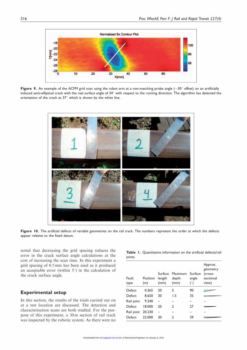
noted that decreasing the grid spacing reduces theerror in the crack surface angle calculations at thecost of increasing the scan time. In this experiment agrid spacing of 0.5mm has been used as it producedan acceptable error (within 5�) in the calculation ofthe crack surface angle.
Experimental setup
In this section, the results of the trials carried out onat a test location are discussed. The detection andcharacterisation scans are both studied. For the pur-pose of this experiment, a 30m section of rail trackwas inspected by the robotic system. As there were no
Figure 10. The artificial defects of variable geometries on the rail track. The numbers represent the order at which the defects
appear relative to the fixed datum.
Figure 9. An example of the ACFM grid scan using the robot arm at a non-matching probe angle (�30� offset) on an artificially
induced semi-elliptical crack with the real surface angle of 34� with respect to the running direction. The algorithm has detected the
orientation of the crack as 37� which is shown by the white line.
Table 1. Quantitative information on the artificial defects/rail
joints.
Fault
type
Position
(m)
Surface
length
(mm)
Maximum
depth
(mm)
Surface
angle
(�)
Approx.
geometry
(cross-
sectional
view)
Defect 0.365 20 5 90
Defect 8.650 30 1.5 35
Rail joint 9.240 – – – –
Defect 18.000 20 2 27
Rail joint 20.230 – – – –
Defect 22.000 30 2 39
316 Proc IMechE Part F: J Rail and Rapid Transit 227(4)
at Inst. of Mechanical Engineers on January 9, 2014pif.sagepub.comDownloaded from

indications of RCF defects on the desired section ofthe track, several artificial defects of simple geometrywere induced at different positions along the railtrack in order to mimic RCF cracks (Figure 10).The inspection length also contained two rail joints.The positions of these defects/joints were measuredwith respect to a fixed datum on the rail track,see Table 1.
Results
Detection scan
The rail was inspected by the robotic system at aspeed of 5 km=h while the ACFM probe was held atan initial lift-off of 3mm and an angle of 45� withrespect to the running direction. The results of two
Figure 11. The results of detection scan with the robotic system at 5 km=h with an initial ACFM probe lift-off of 3 mm and an angle
of 45� to the running direction for the (a) first and (b) second trials. In each of (a) and (b) above the top graph represents the Bx signal,
the middle graph represents the relative change of Bx signal with respect to its local background (�Bx) and the bottom graph
represents the instantaneous position of the trolley.
Rowshandel et al. 317
at Inst. of Mechanical Engineers on January 9, 2014pif.sagepub.comDownloaded from
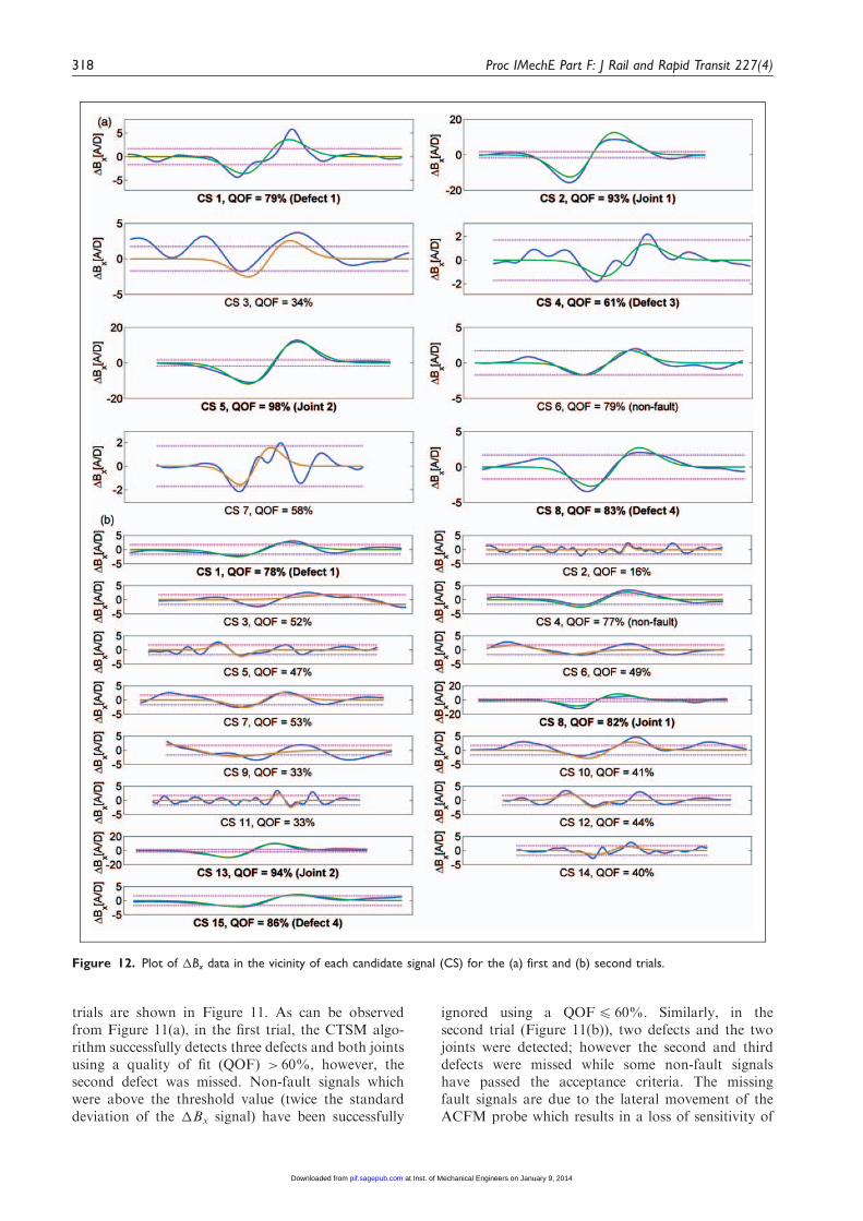
trials are shown in Figure 11. As can be observedfrom Figure 11(a), in the first trial, the CTSM algo-rithm successfully detects three defects and both jointsusing a quality of fit (QOF) > 60%, however, thesecond defect was missed. Non-fault signals whichwere above the threshold value (twice the standarddeviation of the �Bx signal) have been successfully
ignored using a QOF4 60%. Similarly, in thesecond trial (Figure 11(b)), two defects and the twojoints were detected; however the second and thirddefects were missed while some non-fault signalshave passed the acceptance criteria. The missingfault signals are due to the lateral movement of theACFM probe which results in a loss of sensitivity of
Figure 12. Plot of �Bx data in the vicinity of each candidate signal (CS) for the (a) first and (b) second trials.
318 Proc IMechE Part F: J Rail and Rapid Transit 227(4)
at Inst. of Mechanical Engineers on January 9, 2014pif.sagepub.comDownloaded from

Figure 14. (a) The normalised contour plot of automatic ACFM scans over the second defect at a constant lift-off of 3 mm and
orientation angle of 45� relative to the running direction. The white line shows the crack orientation (32.5�) as calculated by the
automatic crack surface angle detection algorithm. (b) The rail profile measured by the robot arm using the laser distance sensor in the
vicinity of the second defect. (c) Comparison between the COMSOL simulation and experimental result of the ACFM scan over the
second defect at 3 mm lift-off and relative angle offset of 10�.
Figure 13. The real-time position and velocity plot of the robotic system travelling to the location of the second defect which is at
8.65 m relative to the datum.
Rowshandel et al. 319
at Inst. of Mechanical Engineers on January 9, 2014pif.sagepub.comDownloaded from

the ACFM signal to a defect (either due to excessivelift-off or deviation of the probe from the fault). Inaddition, any sudden up-down movement of theprobe due to mechanical imbalances such as misalign-ment of the rail tracks at the rail joint has the poten-tial to develop a crack-like signature as the ACFMsignal is lift-off dependent. Figure 12 shows a moredetailed plot of the candidate signals withQOF> 60% and4 60%. The limitations in ACFMprobe lift off and trolley hunting could be addressedusing ACFM array sensors to cover wider area of therail head.
Characterisation scan
To study the characterisation scan independently, theknown position of the second defect was given to theGUI software. The robotic system was theninstructed to move forward at a constant speedand stop in close proximity (within 30mm) of thesecond defect which is located 8.65mm relative tothe datum. The position control mode becameactive once the absolute position error fell below1.5m. Figure 13 demonstrates the real-time positionand speed of the robotic system as recorded by thesoftware until convergence. As it can be observed,the robotic system successfully stopped in the vicinityof the defect with a position error of 23mm.Subsequently, the system was instructed to performa characterisation scan over the defect. This wasinitiated by first performing a profile measurementfollowed by a constant ACFM probe lift-off of3mm and orientation angle of 45� with respect tothe running direction. Figure 14(a) shows the resultof 3D ACFM scans over the measured profile(Figure 14(b)). The sensor output has been normal-ised with respect to its background level.10 The max-imum signal reduction scan line has also beencompared with COMSOL simulation data for acrack of 1.5mm depth (details of the COMSOLmodelling approach can be found in Nicholson andDavis5 and is carried out assuming a flat surfacerather than the curved rail surface) which showsclose agreement (Figure 14(c)). This close agreementindicates that the signal can be used with the sizingalgorithm (based on the COMSOL modelling) togive accurate crack sizes. The initial ACFM orienta-tion angle of 45� was chosen to give a 10� angleoffset relative to the defect which, if not taken intoaccount, will cause the crack depth to be underesti-mated. Following the constant lift-off ACFM scanover the measured rail profile, the on-line cracksurface angle detection algorithm reported a cracksurface angle of 32.5� which when taken intoaccount, leads to a reduced angle offset of 2.5�.This demonstrates the capability of the developedrobotic system to autonomously travel to a desiredlocation and obtain high quality and reliable data onthe unknown defect.
Conclusions
Experimental results from robotic inspection, usingan automated trolley, of the artificial defects on railtracks, have demonstrated that the developed systemhas the capability to both detect and characterise sur-face-breaking defects autonomously (the applicabilityof ACFM for sizing of real RCF defects has been pre-viously confirmed in a different study13). Therefore,the system can be used to improve on the accuracyand reliability of existing inspection systems (e.g.hand-held ACFM walking stick) in crack sizing bytaking constant lift-off ACFM measurements alongthe crack’s opening at close to the optimum conditionwhere the relative offset angle between the ACFMprobe and the unknown crack is bounded to bewithin 5�. The use of a CTSM algorithm, ratherthan a simple threshold approach, has a high reliabil-ity in automatically detecting the surface-breakingdefects even in the presence of lift-off change and pro-cess noise, although it is still necessary for the ACFMsensor to pass directly over the defects. This limitationmay be addressed by employing ACFM array sensorswhich survey a wider area of the rail head in oneinspection pass. It was also found that any suddenup-down movement of the ACFM probe can developcrack-like signatures which could pass the detectioncriterion of the CTSM algorithm. This event, how-ever, could be detected by simultaneously monitoringthe ACFM sensor lift-off using a low-cost laser dis-tance sensor.
Funding
This research has received funding from the European
Community’s Seventh Framework Programme (FP7/2007-2013) under grant SCP8-GA-2009-234040 (INTERAILProject www.interailproject.eu).
Acknowledgement
Special thanks are due to the members of staff at LongMarston Railway for provision of their facilities and timeduring the field trials.
References
1. Papaelias MP, Roberts C and Davis CL. A review onnon-destructive evaluation of rails: state-of-the-art andfuture development. Proc IMechE, Part F: J Rail RapidTransit 2008; 222: 367–384.
2. Gaynor T, Roberts D, Homan E and Dover W.Reduction in fatigue failures through crack detectionby alternating current field measurement. SPE Drilling
& Completion 1997; 12: 37–42.3. Papaelias MP and Lugg M. Detection and evaluation of
rail surface defects using alternating current field meas-
urement techniques. Proc IMechE, Part F: J Rail RapidTransit 2012; 226: 530–541.
4. Papaelias MP, Lugg MC, Roberts C and Davis CL.
High-speed inspection of rails using ACFM techniques.NDT & E Int 2009; 42: 328–335.
320 Proc IMechE Part F: J Rail and Rapid Transit 227(4)
at Inst. of Mechanical Engineers on January 9, 2014pif.sagepub.comDownloaded from

5. Nicholson GL and Davis CL. Modelling of the responseof an ACFM sensor to rail and rail wheel RCF cracks.NDT & E Int 2012; 46: 107–114.
6. Rowshandel H, Nicholson GL, Davis CL and RobertsC. A robotic system for non-destructive evaluation ofRCF cracks in rails using an ACFM sensor. In: The
fifth IET conference on railway condition monitoring andnon-destructive testing, Derby, UK, 29–30 November,2011, pp.1–6.
7. Stock R and Pippan R. RCF and wear in theory andpractice—the influence of rail grade on wear and RCF.Wear 2011; 271: 125–133.
8. Lugg M, Topp D and Keynes M. Recent developments
and applications of the ACFM inspection method andACSM stress measurement method. In: Proceedings ofECNDT. Berlin, Germany 2006.
9. Ravan M, Sadeghi SHH and Moini R. Using a waveletnetwork for reconstruction of fatigue crack depth profilefrom AC field measurement signals. NDT & E Int 2007;
40: 537–544.
10. Ravan M, Sadeghi SHH and Moini R. Neural networkapproach for determination of fatigue crack depth pro-file in a metal, using alternating current field measure-
ment data. IET Sci Meas Technol 2008; 2: 32–38.11. Rowshandel H, Nicholson GL, Davis CL and Roberts
C. A robotic approach for NDT of RCF cracks in rails
using an ACFM sensor. Insight -Non-Destr Test CondMonit 2011; 53: 368–376.
12. Ziegler JG and Nichols NB. Optimum settings for auto-
matic controllers. J Dyn Syst Meas Control 1993; 115:220–222.
13. Nicholson GL, Kostryzhev AG, Hao XJ and Davis CL.Modelling and experimental measurements of idealised
and light-moderate RCF cracks in rails using an ACFMsensor. NDT & E Int 2011; 44: 427–437.
Rowshandel et al. 321
at Inst. of Mechanical Engineers on January 9, 2014pif.sagepub.comDownloaded from