proceedings of the institution of mechanical engineers...
TRANSCRIPT
http://pic.sagepub.com/Engineering Science
Engineers, Part C: Journal of Mechanical Proceedings of the Institution of Mechanical
http://pic.sagepub.com/content/217/1/1The online version of this article can be found at:
DOI: 10.1243/095440603762554569
1 2003 217:Proceedings of the Institution of Mechanical Engineers, Part C: Journal of Mechanical Engineering Science
D T Pham and S S Dimovthe key enablers for rapid manufacturing−−Rapid prototyping and rapid tooling
Published by:
http://www.sagepublications.com
On behalf of:
Institution of Mechanical Engineers
can be found at:Engineering ScienceProceedings of the Institution of Mechanical Engineers, Part C: Journal of MechanicalAdditional services and information for
http://pic.sagepub.com/cgi/alertsEmail Alerts:
http://pic.sagepub.com/subscriptionsSubscriptions:
http://www.sagepub.com/journalsReprints.navReprints:
http://www.sagepub.com/journalsPermissions.navPermissions:
http://pic.sagepub.com/content/217/1/1.refs.htmlCitations:
What is This?
- Jan 1, 2003Version of Record >>
at Cardiff University on April 4, 2012pic.sagepub.comDownloaded from
SPECIAL ISSUE PAPER
Rapid prototyping and rapid tooling—the key enablersfor rapid manufacturing
D T Pham* and S S DimovManufacturing Engineering Centre, School of Engineering, Cardiff University, Wales, UK
Abstract: Rapid manufacturing is a new mode of operation that can greatly improve the competitiveposition of companies adopting it. The key enabling technologies of rapid manufacturing are rapidprototyping (RP) and rapid tooling (RT). This paper classi�es the existing RP processes and brie�ydescribes those with actual or potential commercial impact. The paper then discusses �ve importantRP applications: building functional prototypes, producing casting patterns, making medical andsurgical models, creating artworks and fabricating models to assist engineering analysis. F inally, thepaper gives an overview of indirect and direct RT methods for quickly producing up to severalthousand parts together with examples illustrating different applications of RT.
Keywords: rapid prototyping, rapid tooling, rapid manufacturing
1 INTRODUCTION
Global competition, mass customization, acceleratedproduct obsolescence and continued demands for costsavings are forcing companies to look for new ways toimprove their business processes. Rapid prototyping(RP) and rapid tooling (RT) have emerged as keyenablers for rapid manufacturing, a new mode ofoperation promising improvements to the competitiveposition of companies adopting it.
RP is a technology for quickly fabricating physicalmodels, functional prototypes and small batches of partsdirectly from computer aided design (CAD) data. RTgenerally concerns the production of moulds and toolinginserts using RP. RP and RT are means for compressingthe time-to-market of products and, as such, arecompetitiveness-enhancing technologies.
This paper starts with a classi�cation of existing RPprocesses and a brief description of those currently witha signi�cant commercial impact or expected to be insuch a position in the near future. Five differentapplication areas of RP are discussed, in particular:building functional prototypes, patterns for castings,medical and surgical models, artworks and models forengineering analysis. The paper then reviews indirect
and direct RT methods that are, or shortly will be,available for production runs of up to several thousandparts in a material identical or very similar to that of the�nal production part. Three examples illustratingdifferent applications of RT conclude the paper.
2 RAPID PROTOTYPING
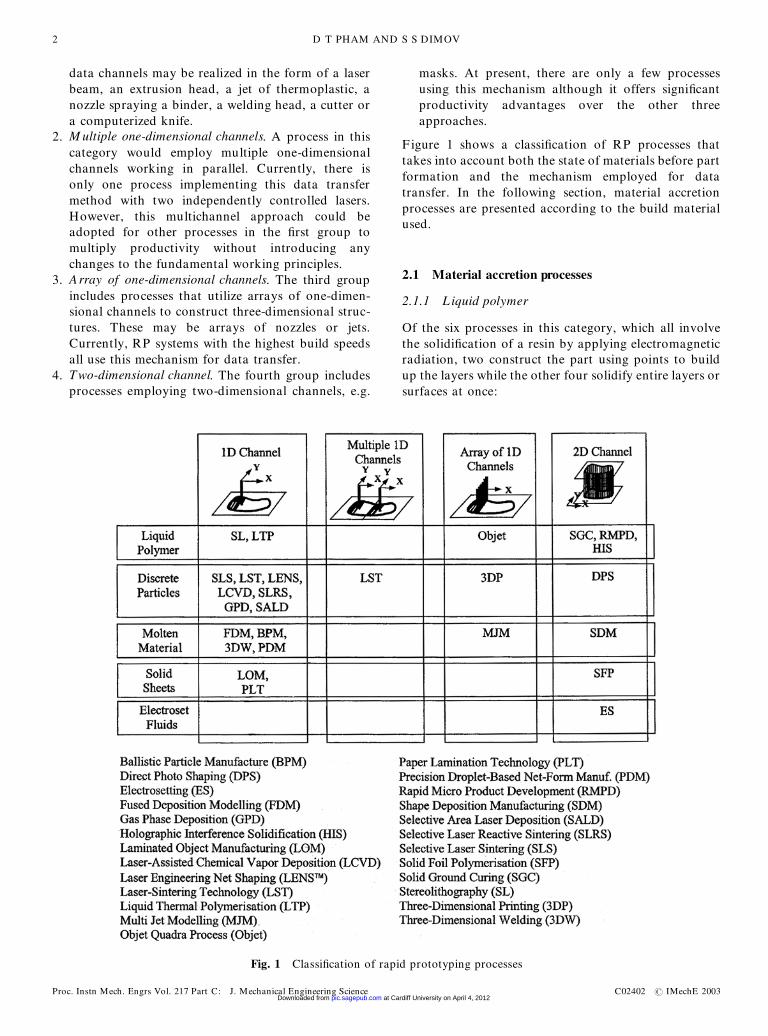
RP processes may be divided broadly into thoseinvolving the addition or the removal of material.According to Kruth [1], material accretion processesmay be categorized by the state of the prototypematerial before part formation, namely liquid, powderor solid sheets. Liquid-based processes may entail thesolidi�cation of a resin on contact with a laser, thesolidi�cation of an electrosetting �uid or the melting andsubsequent solidi�cation of the prototype material.Processes using powders (discrete particles) aggregatethem either with a laser or by the selective application ofbinding agents. Those processes that employ solid sheetsmay be classi�ed into two types depending on whetherthe sheets are bonded with light or with an adhesive.
Material accretion processes may also be clusteredaccording to the mechanism employed for transferringdata from the sliced three-dimensional models intophysical structures. Following this method of categor-ization, the processes fall into one of four groups:
1. One-dimensional channel. The �rst group of processestransfers data using one-dimensional channels. These
The M S was received on 19 February 2002 and was accepted afterrevision for publication on 25 July 2002.* Corresponding author: M anufacturing Engineering Centre, School ofEngineering, Cardiff University, PO Box 925, Newport Road, CardiffCF24 OY F, UK.
1
C02402 # IMechE 2003 Proc. Instn Mech. Engrs Vol. 217 Part C: J. Mechanical Engineering Science at Cardiff University on April 4, 2012pic.sagepub.comDownloaded from
data channels may be realized in the form of a laserbeam, an extrusion head, a jet of thermoplastic, anozzle spraying a binder, a welding head, a cutter ora computerized knife.
2. M ultiple one-dimensional channels. A process in thiscategory would employ multiple one-dimensionalchannels working in parallel. Currently, there isonly one process implementing this data transfermethod with two independently controlled lasers.However, this multichannel approach could beadopted for other processes in the �rst group tomultiply productivity without introducing anychanges to the fundamental working principles.
3. Array of one-dimensional channels. The third groupincludes processes that utilize arrays of one-dimen-sional channels to construct three-dimensional struc-tures. These may be arrays of nozzles or jets.Currently, RP systems with the highest build speedsall use this mechanism for data transfer.
4. Two-dimensional channel. The fourth group includesprocesses employing two-dimensional channels, e.g.
masks. At present, there are only a few processesusing this mechanism although it offers signi�cantproductivity advantages over the other threeapproaches.
F igure 1 shows a classi�cation of RP processes thattakes into account both the state of materials before partformation and the mechanism employed for datatransfer. In the following section, material accretionprocesses are presented according to the build materialused.
2.1 Material accretion processes
2.1.1 L iquid polymer
Of the six processes in this category, which all involvethe solidi�cation of a resin by applying electromagneticradiation, two construct the part using points to buildup the layers while the other four solidify entire layers orsurfaces at once:
Fig. 1 Classi�cation of rapid prototyping processes
D T PHAM AND S S DIMOV2
Proc. Instn Mech. Engrs Vol. 217 Part C: J. Mechanical Engineering Science C02402 # IMechE 2003 at Cardiff University on April 4, 2012pic.sagepub.comDownloaded from
1. Stereolithography ( SL ) . This process relies on aphotosensitive liquid resin which forms a solidpolymer when exposed to ultraviolet (UV) light. SLsystems consist of a build platform (substrate) whichis mounted in a vat of resin and a UV helium–cadmium or argon ion laser [2]. The �rst layer of thepart is imaged on the resin surface by the laser usinginformation obtained from the three-dimensionalsolid CAD model. Once the contour of the layerhas been scanned and the interior hatched, theplatform is lowered and a new layer of resin isapplied. The next layer may then be scanned. Oncethe part is completed, it is removed from the vat andthe excess resin drained. The ‘green’ part is thenplaced in a UV oven to be post-cured. To broadenthe application area of SL, research and technologydevelopment efforts have been directed towardsprocess optimization [3, 4].
2. L iquid thermal polymerization ( LTP) . This process issimilar to SL except that the resin is thermosettingand an infrared laser is used to create voxels (three-dimensional pixels). This means that the size of thevoxels may be affected through heat dissipation,which can also cause unwanted distortion andshrinkage in the part [1]. The system is still beingresearched.
3. Holographic interference solidi�cation ( HIS) . Aholographic image is projected into the resin, causingan entire surface to solidify. Data are still obtainedfrom the CAD model, although not as slices [1].There are no commercial systems available yet.
4. Solid ground curing ( SGC) . This system again utilizesphotopolymerizing resins and UV light [5]. Datafrom the CAD model are used to produce electro-statically a mask on a glass that is developed using atoner. Then the mask is placed above the resinsurface and the entire layer is illuminated with apowerful UV lamp. Once the layer has been cured,the excess resin is wiped away and any spaces are�lled with wax. The wax is cooled with a chill plate,milled �at and the wax chips removed. A new layer ofresin is applied and the process is repeated.
5. Rapid micro product development ( RM PD) . TheRMPD process is a mask-based technology verysimilar to that of photolithography as used inmicroelectronics manufacture [6]. CAD data areemployed to produce masks for laser polymerizationof a liquid photoresin in a layer-by-layer fashion. Theprocess allows micro components to be built with aminimum layer thickness of 1 mm and X–Y resolutionof 10 mm. In addition, this process can be used tocreate complex micro systems that integrate electro-nics, optical and mechanical components.
6. Objet Quadra process. The process employs 1536nozzles to build parts by spreading layers ofphotosensitive resin that are then cured, layer bylayer, using two UV lights. The intensity of the lights
and the exposure are controlled so that modelsproduced by the system do not require post-curing.To support overhanging areas and undercuts, Objetdeposits a second material that can be separatedeasily from the model [7].
2.1.2 M olten material
There are six processes that involve the melting andsubsequent solidi�cation of the part material. Of these,the �rst �ve deposit the material at discrete points whilethe sixth manufactures whole layers at once:
1. Ballistic particle manufacture ( BPM ) . The processbuilds parts by ejecting a stream of molten materialfrom a nozzle. The stream separates into dropletsthat hit the substrate and immediately cold-weld toform the part [8]. Commercial systems based on thisprocess were available until 1998.
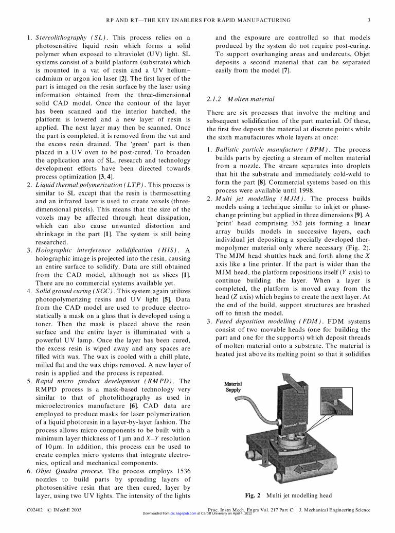
2. M ulti jet modelling ( M JM ) . The process buildsmodels using a technique similar to inkjet or phase-change printing but applied in three dimensions [9]. A‘print’ head comprising 352 jets forming a lineararray builds models in successive layers, eachindividual jet depositing a specially developed ther-mopolymer material only where necessary (Fig. 2).The MJM head shuttles back and forth along the Xaxis like a line printer. If the part is wider than theMJM head, the platform repositions itself (Y axis) tocontinue building the layer. When a layer iscompleted, the platform is moved away from thehead (Z axis) which begins to create the next layer. Atthe end of the build, support structures are brushedoff to �nish the model.
3. Fused deposition modelling ( FDM ) . FDM systemsconsist of two movable heads (one for building thepart and one for the supports) which deposit threadsof molten material onto a substrate. The material isheated just above its melting point so that it solidi�es
Fig. 2 Multi jet modelling head
RP AND RT—THE KEY ENABLERS FOR RAPID MANUFACTURING 3
C02402 # IMechE 2003 Proc. Instn Mech. Engrs Vol. 217 Part C: J. Mechanical Engineering Science at Cardiff University on April 4, 2012pic.sagepub.comDownloaded from
immediately after extrusion and cold-welds to theprevious layers [10].
4. Three-dimensional welding ( 3DW ) . This experimentalsystem uses an arc-welding robot to deposit materialon a platform as simple shapes which may then bebuilt into more complex structures [11]. Unlike mostRP processes, the prototypes are built using compu-ter numerically controlled (CNC) programs gener-ated directly from the CAD �les instead of employingslice data. Another experimental system deposits theweld material in layers. Feedback control is estab-lished by means of thermocouples which monitor thetemperature and operate an on-line water coolingsystem. A grit-blasting nozzle minimizes the oxidiza-tion of the part and a suction pump and vacuumnozzle remove excess water vapour and grit [12].
5. Precision droplet-based net-form manufacturing( PDM ) . This is a droplet-based net-forming manu-facturing technique [13]. The process exploits thecapillary instability phenomenon of liquid jets forproducing uniform liquid metal droplets. The ther-mal state and mass �ux of the droplets can becontrolled to tailor the microstructure of the deposit.There is no commercial system based on this process.
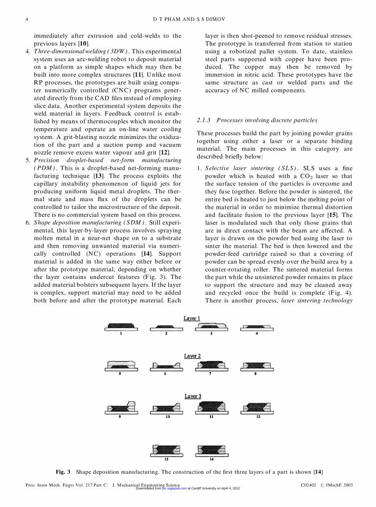
6. Shape deposition manufacturing ( SDM ) . Still experi-mental, this layer-by-layer process involves sprayingmolten metal in a near-net shape on to a substrateand then removing unwanted material via numeri-cally controlled (NC) operations [14]. Supportmaterial is added in the same way either before orafter the prototype material, depending on whetherthe layer contains undercut features (F ig. 3). Theadded material bolsters subsequent layers. If the layeris complex, support material may need to be addedboth before and after the prototype material. Each
layer is then shot-peened to remove residual stresses.The prototype is transferred from station to stationusing a robotized pallet system. To date, stainlesssteel parts supported with copper have been pro-duced. The copper may then be removed byimmersion in nitric acid. These prototypes have thesame structure as cast or welded parts and theaccuracy of NC milled components.
2.1.3 Processes involving discrete particles
These processes build the part by joining powder grainstogether using either a laser or a separate bindingmaterial. The main processes in this category aredescribed brie�y below:
1. Selective laser sintering ( SLS) . SLS uses a �nepowder which is heated with a CO2 laser so thatthe surface tension of the particles is overcome andthey fuse together. Before the powder is sintered, theentire bed is heated to just below the melting point ofthe material in order to minimize thermal distortionand facilitate fusion to the previous layer [15]. Thelaser is modulated such that only those grains thatare in direct contact with the beam are affected. Alayer is drawn on the powder bed using the laser tosinter the material. The bed is then lowered and thepowder-feed cartridge raised so that a covering ofpowder can be spread evenly over the build area by acounter-rotating roller. The sintered material formsthe part while the unsintered powder remains in placeto support the structure and may be cleaned awayand recycled once the build is complete (F ig. 4).There is another process, laser sintering technology
Fig. 3 Shape deposition manufacturing. The construction of the �rst three layers of a part is shown [14]
D T PHAM AND S S DIMOV4
Proc. Instn Mech. Engrs Vol. 217 Part C: J. Mechanical Engineering Science C02402 # IMechE 2003 at Cardiff University on April 4, 2012pic.sagepub.comDownloaded from
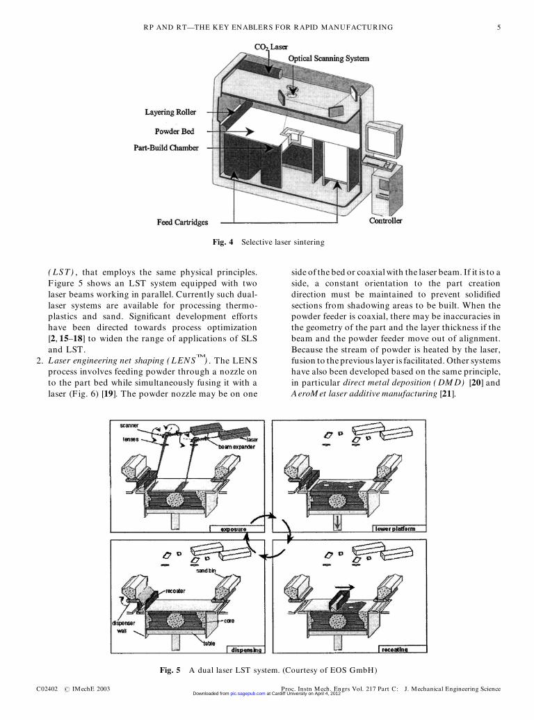
( LST) , that employs the same physical principles.F igure 5 shows an LST system equipped with twolaser beams working in parallel. Currently such dual-laser systems are available for processing thermo-plastics and sand. Signi�cant development effortshave been directed towards process optimization[2, 15–18] to widen the range of applications of SLSand LST.
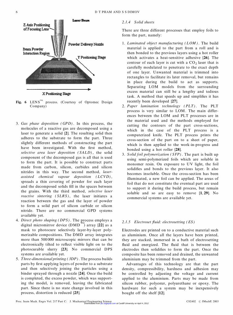
2. Laser engineering net shaping ( LENSTM
) . The LENSprocess involves feeding powder through a nozzle onto the part bed while simultaneously fusing it with alaser (F ig. 6) [19]. The powder nozzle may be on one
side of the bed or coaxialwith the laser beam. If it is to aside, a constant orientation to the part creationdirection must be maintained to prevent solidi�edsections from shadowing areas to be built. When thepowder feeder is coaxial, there may be inaccuracies inthe geometry of the part and the layer thickness if thebeam and the powder feeder move out of alignment.Because the stream of powder is heated by the laser,fusion to the previous layer is facilitated. Other systemshave also been developed based on the same principle,in particular direct metal deposition ( DM D) [20] andAeroM et laser additive manufacturing [21].
Fig. 4 Selective laser sintering
Fig. 5 A dual laser LST system. (Courtesy of EOS GmbH)
RP AND RT—THE KEY ENABLERS FOR RAPID MANUFACTURING 5
C02402 # IMechE 2003 Proc. Instn Mech. Engrs Vol. 217 Part C: J. Mechanical Engineering Science at Cardiff University on April 4, 2012pic.sagepub.comDownloaded from
3. Gas phase deposition ( GPD) . In this process, themolecules of a reactive gas are decomposed using alaser to generate a solid [2]. The resulting solid thenadheres to the substrate to form the part. Threeslightly different methods of constructing the parthave been investigated. With the �rst method,selective area laser deposition ( SALD) , the solidcomponent of the decomposed gas is all that is usedto form the part. It is possible to construct partsmade from carbon, silicon, carbides and siliconnitrides in this way. The second method, laser-assisted chemical vapour deposition ( LCVD) ,spreads a thin covering of powder for each layerand the decomposed solids �ll in the spaces betweenthe grains. With the third method, selective laserreactive sintering ( SLRS ) , the laser initiates areaction between the gas and the layer of powderto form a solid part of silicon carbide or siliconnitride. There are no commercial GPD systemsavailable yet.
4. Direct photo shaping ( DPS) . The process employs adigital micromirror device (DMD
TM
) array [22] as amask to photocure selectively layer-by-layer poly-merizable compositions. The DMD array integratesmore than 500 000 microscopic mirrors that can beelectronically tilted to re�ect visible light on to thephotocurable slurry [23]. No commercial DPSsystems are available yet.
5. Three-dimensional printing ( 3DP) . The process buildsparts by �rst applying layers of powder to a substrateand then selectively joining the particles using abinder sprayed through a nozzle [24]. Once the buildis completed, the excess powder, which was support-ing the model, is removed, leaving the fabricatedpart. Since there is no state change involved in thisprocess, distortion is reduced [25].
2.1.4 Solid sheets
There are three different processes that employ foils toform the part, namely:
1. Laminated object manufacturing ( LOM ) . The buildmaterial is applied to the part from a roll and isthen bonded to the previous layers using a hot rollerwhich activates a heat-sensitive adhesive [26]. Thecontour of each layer is cut with a CO2 laser that iscarefully modulated to penetrate to the exact depthof one layer. Unwanted material is trimmed intorectangles to facilitate its later removal, but remainsin place during the build to act as supports.Separating LOM models from the surroundingexcess material can still be a lengthy and tedioustask. A method that speeds up and simpli�es it hasrecently been developed [27].
2. Paper lamination technology ( PLT) . The PLTprocess is very similar to LOM. The main differ-ences between the LOM and PLT processes are inthe material used and the methods employed forcutting the contours of the part cross-sections,which in the case of the PLT process is acomputerized knife. The PLT process prints thecross-section of the part on to a sheet of paper,which is then applied to the work-in-progress andbonded using a hot roller [28].
3. Solid foil polymerization ( SFP) . The part is built upusing semi-polymerized foils which are soluble inmonomer resin. On exposure to UV light, the foilsolidi�es and bonds to the previous layer. It alsobecomes insoluble. Once the cross-section has beenilluminated, a new foil can be applied. The areas offoil that do not constitute the eventual part are usedto support it during the build process, but remainsoluble and so are easy to remove [1, 29]. Nocommercial systems are available yet.
2.1.5 Electroset �uid: electrosetting ( ES)
Electrodes are printed on to a conductive material suchas aluminium. Once all the layers have been printed,they are stacked, immersed in a bath of electrosetting�uid and energized. The �uid that is between theelectrodes then solidi�es to form the part. Once thecomposite has been removed and drained, the unwantedaluminium may be trimmed from the part.
Advantages of this technology are that the partdensity, compressibility, hardness and adhesion maybe controlled by adjusting the voltage and currentapplied to the aluminium. Parts may be made fromsilicon rubber, polyester, polyurethane or epoxy. Thehardware for such a system may be inexpensivelybought off the shelf [12].
Fig. 6 LENSTM
process. (Courtesy of Optomec DesignCompany)
D T PHAM AND S S DIMOV6
Proc. Instn Mech. Engrs Vol. 217 Part C: J. Mechanical Engineering Science C02402 # IMechE 2003 at Cardiff University on April 4, 2012pic.sagepub.comDownloaded from
2.2 Material removal processes
This category includes two processes, desktop milling( DM ) and laser milling ( LM ) . DM is a process thatremoves material from the workpiece, as in traditionalmachining, instead of creating the part by gradualmaterial build-up [30]. Prototypes can be made with ahigh degree of accuracy because they do not deformafter they have been completed.
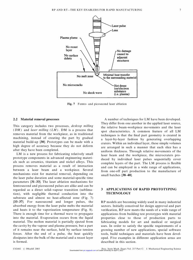
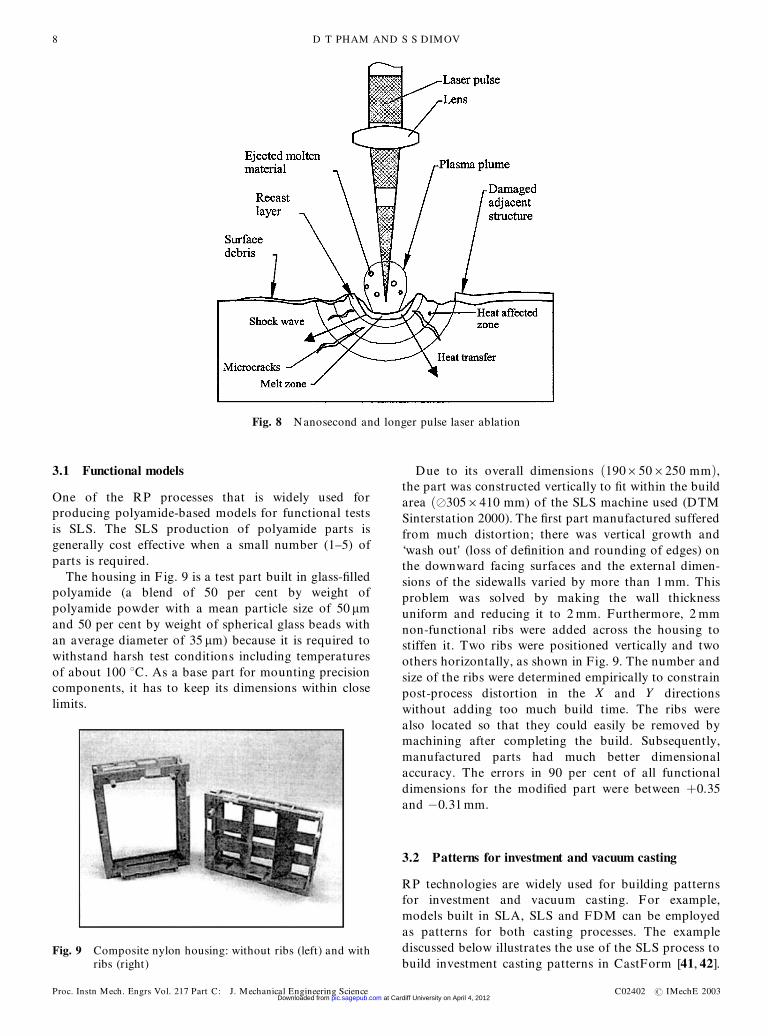
LM is a new process for fabricating relatively smallprototype components in advanced engineering materi-als such as ceramics, titanium and nickel alloys. Thisprocess removes material as a result of interactionbetween a laser beam and a workpiece. Severalmechanisms exist for material removal, depending onthe laser pulse duration and some material-speci�c timeparameters [31–33]. The laser ablation mechanisms forfemtosecond and picosecond pulses are alike and can beregarded as a direct solid–vapour transition (sublima-tion), with negligible thermal conduction into thesubstrate and almost no heat-affected zone (F ig. 7)[33–37]. For nanosecond and longer pulses, theabsorbed energy from the laser pulse melts the materialand heats it to the vaporization temperature (Fig. 8).There is enough time for a thermal wave to propagateinto the material. Evaporation occurs from the liquidmaterial. The molten material is partially ejected fromthe cavity by the vapour and plasma pressure, but a partof it remains near the surface, held by surface tensionforces. After the end of a pulse, the heat quicklydissipates into the bulk of the material and a recast layeris formed.
A number of techniques for LM have been developed.They differ from one another in the applied laser source,the relative beam-workpiece movements and the laserspot characteristics. A common feature of all LMtechniques is that the �nal part geometry is created ina layer-by-layer fashion by generating overlappingcraters. Within an individual layer, these simple volumesare arranged in such a manner that each slice has auniform thickness. Through relative movements of thelaser beam and the workpiece, the microcraters pro-duced by individual laser pulses sequentially covercomplete layers of the part. The LM process is �exibleand can be employed in a wide range of applications,from one-off part production to the manufacture ofsmall batches [38–40].
3 APPLICATIONS OF RAPID PROTOTYPINGTECHNOLOGY
RP models are becoming widely used in many industrialsectors. Initially conceived for design approval and partveri�cation, RP now meets the needs of a wide range ofapplications from building test prototypes with materialproperties close to those of production parts tofabricating models for art and medical or surgicaluses. In order to satisfy the speci�c requirements of agrowing number of new applications, special softwaretools, build techniques and materials have been devel-oped. F ive examples in different application areas aredescribed in this section.
Fig. 7 Femto- and picosecond laser ablation
RP AND RT—THE KEY ENABLERS FOR RAPID MANUFACTURING 7
C02402 # IMechE 2003 Proc. Instn Mech. Engrs Vol. 217 Part C: J. Mechanical Engineering Science at Cardiff University on April 4, 2012pic.sagepub.comDownloaded from
3.1 Functional models
One of the RP processes that is widely used forproducing polyamide-based models for functional testsis SLS. The SLS production of polyamide parts isgenerally cost effective when a small number (1–5) ofparts is required.
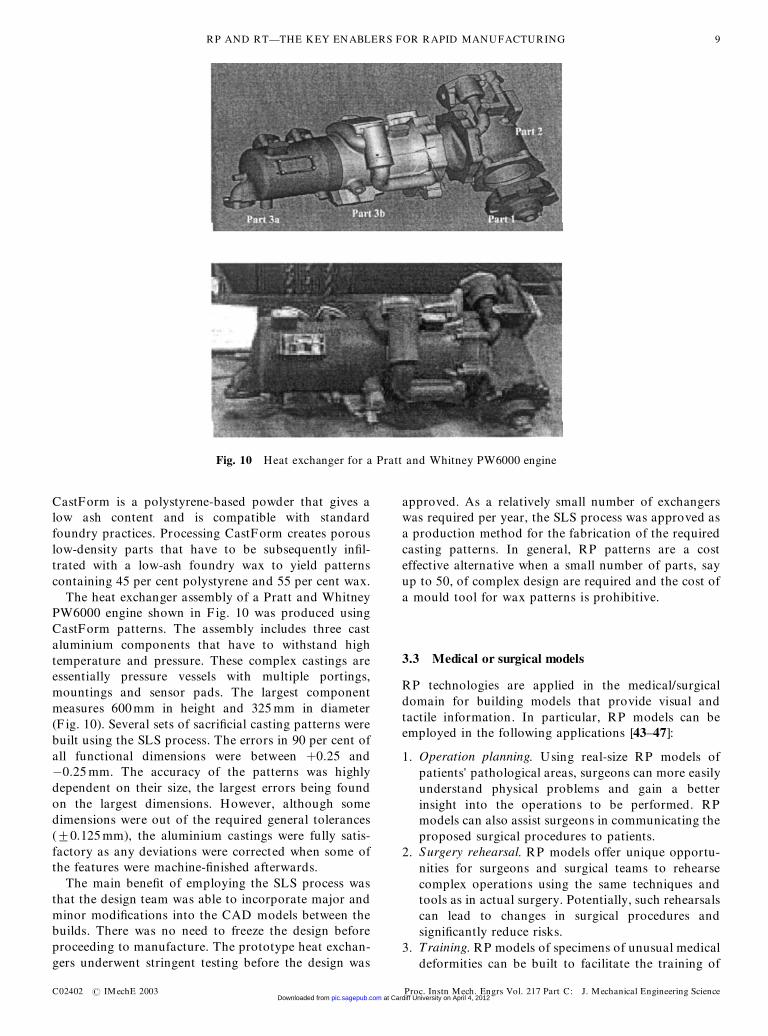
The housing in F ig. 9 is a test part built in glass-�lledpolyamide (a blend of 50 per cent by weight ofpolyamide powder with a mean particle size of 50 mmand 50 per cent by weight of spherical glass beads withan average diameter of 35 mm) because it is required towithstand harsh test conditions including temperaturesof about 100 8C. As a base part for mounting precisioncomponents, it has to keep its dimensions within closelimits.
Due to its overall dimensions …1906506250 mm†,the part was constructed vertically to �t within the buildarea …¬3056410 mm) of the SLS machine used (DTMSinterstation 2000). The �rst part manufactured sufferedfrom much distortion; there was vertical growth and‘wash out’ (loss of de�nition and rounding of edges) onthe downward facing surfaces and the external dimen-sions of the sidewalls varied by more than 1 mm. Thisproblem was solved by making the wall thicknessuniform and reducing it to 2 mm. Furthermore, 2 mmnon-functional ribs were added across the housing tostiffen it. Two ribs were positioned vertically and twoothers horizontally, as shown in Fig. 9. The number andsize of the ribs were determined empirically to constrainpost-process distortion in the X and Y directionswithout adding too much build time. The ribs werealso located so that they could easily be removed bymachining after completing the build. Subsequently,manufactured parts had much better dimensionalaccuracy. The errors in 90 per cent of all functionaldimensions for the modi�ed part were between ‡0.35and ¡0.31 mm.
3.2 Patterns for investment and vacuum casting
RP technologies are widely used for building patternsfor investment and vacuum casting. For example,models built in SLA, SLS and FDM can be employedas patterns for both casting processes. The examplediscussed below illustrates the use of the SLS process tobuild investment casting patterns in CastForm [41, 42].
Fig. 9 Composite nylon housing: without ribs (left) and withribs (right)
Fig. 8 Nanosecond and longer pulse laser ablation
D T PHAM AND S S DIMOV8
Proc. Instn Mech. Engrs Vol. 217 Part C: J. Mechanical Engineering Science C02402 # IMechE 2003 at Cardiff University on April 4, 2012pic.sagepub.comDownloaded from
CastForm is a polystyrene-based powder that gives alow ash content and is compatible with standardfoundry practices. Processing CastForm creates porouslow-density parts that have to be subsequently in�l-trated with a low-ash foundry wax to yield patternscontaining 45 per cent polystyrene and 55 per cent wax.
The heat exchanger assembly of a Pratt and WhitneyPW6000 engine shown in F ig. 10 was produced usingCastForm patterns. The assembly includes three castaluminium components that have to withstand hightemperature and pressure. These complex castings areessentially pressure vessels with multiple portings,mountings and sensor pads. The largest componentmeasures 600mm in height and 325 mm in diameter(F ig. 10). Several sets of sacri�cial casting patterns werebuilt using the SLS process. The errors in 90 per cent ofall functional dimensions were between ‡0.25 and¡0.25 mm. The accuracy of the patterns was highlydependent on their size, the largest errors being foundon the largest dimensions. However, although somedimensions were out of the required general tolerances(+0.125 mm), the aluminium castings were fully satis-factory as any deviations were corrected when some ofthe features were machine-�nished afterwards.
The main bene�t of employing the SLS process wasthat the design team was able to incorporate major andminor modi�cations into the CAD models between thebuilds. There was no need to freeze the design beforeproceeding to manufacture. The prototype heat exchan-gers underwent stringent testing before the design was
approved. As a relatively small number of exchangerswas required per year, the SLS process was approved asa production method for the fabrication of the requiredcasting patterns. In general, RP patterns are a costeffective alternative when a small number of parts, sayup to 50, of complex design are required and the cost ofa mould tool for wax patterns is prohibitive.
3.3 Medical or surgical models
RP technologies are applied in the medical/surgicaldomain for building models that provide visual andtactile information. In particular, RP models can beemployed in the following applications [43–47]:
1. Operation planning. Using real-size RP models ofpatients’ pathological areas, surgeons can more easilyunderstand physical problems and gain a betterinsight into the operations to be performed. RPmodels can also assist surgeons in communicating theproposed surgical procedures to patients.
2. Surgery rehearsal. RP models offer unique opportu-nities for surgeons and surgical teams to rehearsecomplex operations using the same techniques andtools as in actual surgery. Potentially, such rehearsalscan lead to changes in surgical procedures andsigni�cantly reduce risks.
3. Training. RP models of specimens of unusual medicaldeformities can be built to facilitate the training of
Fig. 10 Heat exchanger for a Pratt and Whitney PW6000 engine
RP AND RT—THE KEY ENABLERS FOR RAPID MANUFACTURING 9
C02402 # IMechE 2003 Proc. Instn Mech. Engrs Vol. 217 Part C: J. Mechanical Engineering Science at Cardiff University on April 4, 2012pic.sagepub.comDownloaded from
student surgeons and radiologists. Such models canalso be employed for student examinations.
4. Prosthesis design. RP models can be used to fabricatemaster patterns which are then replicated using abiocompatible plastic material. Implants produced inthis way are much more accurate and cost effectivethan those created conventionally.
The following example, reported by a company inQueensland, Australia, demonstrates the use of RPmodels in the medical domain. Two SLA medicalmodels were built for a patient suffering from asecondary carcinoma of the right superior orbitalmargin and the adjacent frontal bone. The �rst modelwas used to plan the resection of the cancerous bone andalso as an operation reference and patient consent tool.The SLA model can be cut with the same surgical toolsas those used for bone resectioning. A resectionedtemplate was created in plastic following the surgeon’sdesired resection line. The fabricated plastic templatewas placed over the model to check the match with thesurgeon’s resection line (F ig. 11). The second model wasthen employed to construct an acrylic custom implant(F ig. 12). The unaffected left superior orbital marginwas mirrored across to assist the design of the implant.The resection template and the custom implant wereprepared for the operation by gas sterilization. Thetemplate was then placed on to the lesion and theresection line traced out and the bone cut away. F inally,the implant was inserted into the space vacated by theremoved bone. The operation was reported as acomplete success and the surgeon was fully satis�edwith the quality and the cost of utilizing RP models.
3.4 Art models
Another growing application area for RP technologies isart and design. Through building RP models, artists canexperiment with complex artworks that support and
enhance their creativity. Initially, the high cost of RPmodels meant strict limits on the size of the models.However, recently, with the introduction of conceptmodellers, which are relatively inexpensive RP machinesfor quickly producing design models, it has become costeffective to employ RP techniques in many artisticapplications. Taking into account the accuracy of artmodels and the RP materials available, the technologicalcapabilities of concept modellers are more than ade-quate for the majority of art applications.
The two examples described below demonstrate theuse of RP techniques in art. These were part of workconducted within the CALM (creating art with layermanufacture) project [48], which was supported by theHigher Education Funding Council for England as partof an initiative to promote the use of informationtechnology (IT) within the art and design community inUK higher education.
The �rst example is an artwork representing a splashspanning the inside of a plexiglass vitrine (F ig. 13). In its�nal installation, the RP model (F ig. 14) will beincorporated into a plexibox exactly the width of thesplash itself.
The second example is a cybersculpture representingan artefact that cannot be created using any conven-tional methods. The initial intentions of the artist wereto produce an RP pattern and then cast it in bronze.However, after the SLS model (F ig. 15) was built, it wasimmediately recognized that this model, in conjunctionwith the lace-like Moire surface patterns, satis�es theproject requirements [48].
3.5 Engineering analysis models
Computer aided engineering (CAE) analysis is anintegral part of time-compression technologies. Varioussoftware tools exist, mainly based on �nite elementanalysis (FEA), to speed up the development of newproducts by initiating design optimization before
Fig. 11 The SLA model with the resection template [45] Fig. 12 The SLA model together with the template and theimplant [45]
D T PHAM AND S S DIMOV10
Proc. Instn Mech. Engrs Vol. 217 Part C: J. Mechanical Engineering Science C02402 # IMechE 2003 at Cardiff University on April 4, 2012pic.sagepub.comDownloaded from
physical prototypes are available. However, the creationof accurate FEA models for complex engineering objectssometimes requires signi�cant amounts of time andeffort [49–51]. By employing RP techniques it is possibleto begin test programmes on physical models muchearlier and complement the CAE data. Four applica-tions of RP models for engineering analysis aredescribed below:
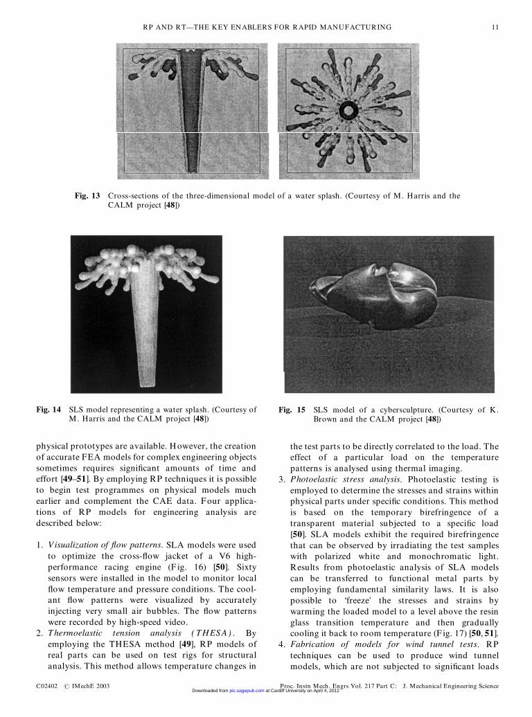
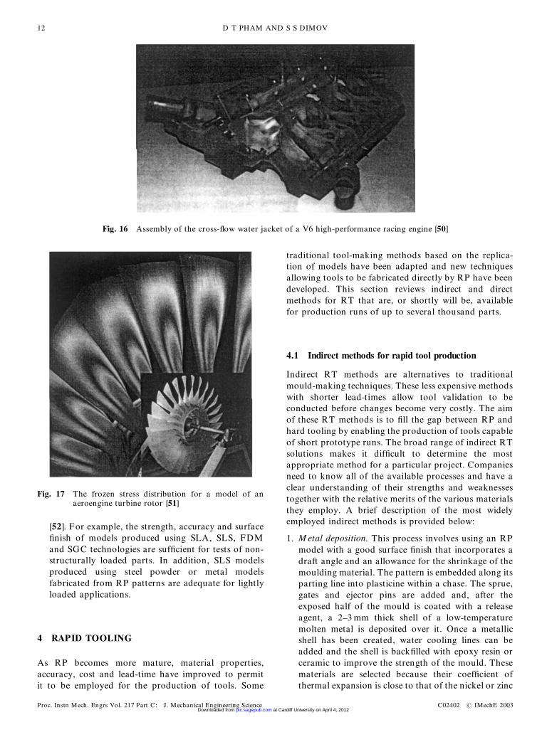
1. Visualization of �ow patterns. SLA models were usedto optimize the cross-�ow jacket of a V6 high-performance racing engine (F ig. 16) [50]. Sixtysensors were installed in the model to monitor local�ow temperature and pressure conditions. The cool-ant �ow patterns were visualized by accuratelyinjecting very small air bubbles. The �ow patternswere recorded by high-speed video.
2. Thermoelastic tension analysis ( THESA) . Byemploying the THESA method [49], RP models ofreal parts can be used on test rigs for structuralanalysis. This method allows temperature changes in
the test parts to be directly correlated to the load. Theeffect of a particular load on the temperaturepatterns is analysed using thermal imaging.
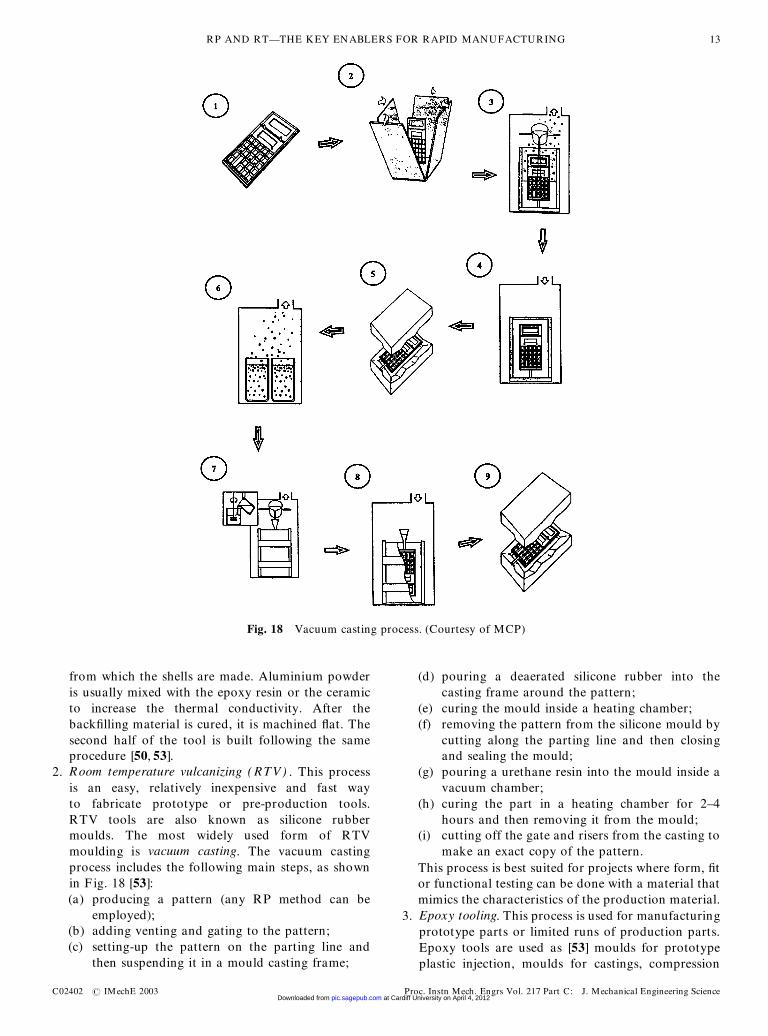
3. Photoelastic stress analysis. Photoelastic testing isemployed to determine the stresses and strains withinphysical parts under speci�c conditions. This methodis based on the temporary birefringence of atransparent material subjected to a speci�c load[50]. SLA models exhibit the required birefringencethat can be observed by irradiating the test sampleswith polarized white and monochromatic light.Results from photoelastic analysis of SLA modelscan be transferred to functional metal parts byemploying fundamental similarity laws. It is alsopossible to ‘freeze’ the stresses and strains bywarming the loaded model to a level above the resinglass transition temperature and then graduallycooling it back to room temperature (F ig. 17) [50, 51].
4. Fabrication of models for wind tunnel tests. RPtechniques can be used to produce wind tunnelmodels, which are not subjected to signi�cant loads
Fig. 14 SLS model representing a water splash. (Courtesy ofM. Harris and the CALM project [48])
Fig. 15 SLS model of a cybersculpture. (Courtesy of K.Brown and the CALM project [48])
Fig. 13 Cross-sections of the three-dimensional model of a water splash. (Courtesy of M. Harris and theCALM project [48])
RP AND RT—THE KEY ENABLERS FOR RAPID MANUFACTURING 11
C02402 # IMechE 2003 Proc. Instn Mech. Engrs Vol. 217 Part C: J. Mechanical Engineering Science at Cardiff University on April 4, 2012pic.sagepub.comDownloaded from
[52]. For example, the strength, accuracy and surface�nish of models produced using SLA, SLS, FDMand SGC technologies are suf�cient for tests of non-structurally loaded parts. In addition, SLS modelsproduced using steel powder or metal modelsfabricated from RP patterns are adequate for lightlyloaded applications.
4 RAPID TOOLING
As RP becomes more mature, material properties,accuracy, cost and lead-time have improved to permitit to be employed for the production of tools. Some
traditional tool-making methods based on the replica-tion of models have been adapted and new techniquesallowing tools to be fabricated directly by RP have beendeveloped. This section reviews indirect and directmethods for RT that are, or shortly will be, availablefor production runs of up to several thousand parts.
4.1 Indirect methods for rapid tool production
Indirect RT methods are alternatives to traditionalmould-making techniques. These less expensive methodswith shorter lead-times allow tool validation to beconducted before changes become very costly. The aimof these RT methods is to �ll the gap between RP andhard tooling by enabling the production of tools capableof short prototype runs. The broad range of indirect RTsolutions makes it dif�cult to determine the mostappropriate method for a particular project. Companiesneed to know all of the available processes and have aclear understanding of their strengths and weaknessestogether with the relative merits of the various materialsthey employ. A brief description of the most widelyemployed indirect methods is provided below:
1. M etal deposition. This process involves using an RPmodel with a good surface �nish that incorporates adraft angle and an allowance for the shrinkage of themoulding material. The pattern is embedded along itsparting line into plasticine within a chase. The sprue,gates and ejector pins are added and, after theexposed half of the mould is coated with a releaseagent, a 2–3 mm thick shell of a low-temperaturemolten metal is deposited over it. Once a metallicshell has been created, water cooling lines can beadded and the shell is back�lled with epoxy resin orceramic to improve the strength of the mould. Thesematerials are selected because their coef�cient ofthermal expansion is close to that of the nickel or zinc
Fig. 16 Assembly of the cross-�ow water jacket of a V6 high-performance racing engine [50]
Fig. 17 The frozen stress distribution for a model of anaeroengine turbine rotor [51]
D T PHAM AND S S DIMOV12
Proc. Instn Mech. Engrs Vol. 217 Part C: J. Mechanical Engineering Science C02402 # IMechE 2003 at Cardiff University on April 4, 2012pic.sagepub.comDownloaded from
from which the shells are made. Aluminium powderis usually mixed with the epoxy resin or the ceramicto increase the thermal conductivity. After theback�lling material is cured, it is machined �at. Thesecond half of the tool is built following the sameprocedure [50, 53].
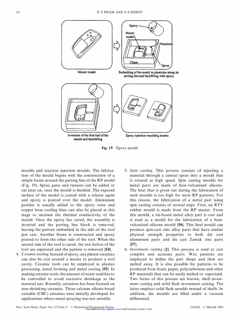
2. Room temperature vulcanizing ( RTV) . This processis an easy, relatively inexpensive and fast wayto fabricate prototype or pre-production tools.RTV tools are also known as silicone rubbermoulds. The most widely used form of RTVmoulding is vacuum casting. The vacuum castingprocess includes the following main steps, as shownin F ig. 18 [53]:(a) producing a pattern (any RP method can be
employed);(b) adding venting and gating to the pattern;(c) setting-up the pattern on the parting line and
then suspending it in a mould casting frame;
(d) pouring a deaerated silicone rubber into thecasting frame around the pattern;
(e) curing the mould inside a heating chamber;(f) removing the pattern from the silicone mould by
cutting along the parting line and then closingand sealing the mould;
(g) pouring a urethane resin into the mould inside avacuum chamber;
(h) curing the part in a heating chamber for 2–4hours and then removing it from the mould;
(i) cutting off the gate and risers from the casting tomake an exact copy of the pattern.
This process is best suited for projects where form, �tor functional testing can be done with a material thatmimics the characteristics of the production material.
3. Epoxy tooling. This process is used for manufacturingprototype parts or limited runs of production parts.Epoxy tools are used as [53] moulds for prototypeplastic injection, moulds for castings, compression
Fig. 18 Vacuum casting process. (Courtesy of MCP)
RP AND RT—THE KEY ENABLERS FOR RAPID MANUFACTURING 13
C02402 # IMechE 2003 Proc. Instn Mech. Engrs Vol. 217 Part C: J. Mechanical Engineering Science at Cardiff University on April 4, 2012pic.sagepub.comDownloaded from
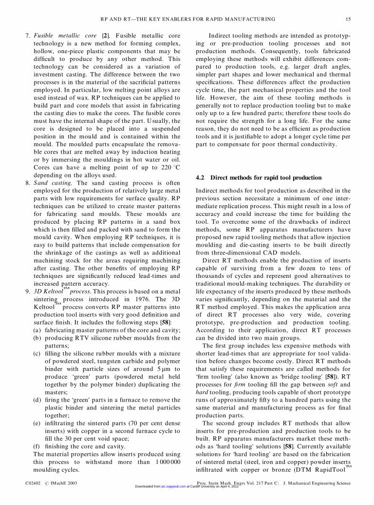
moulds and reaction injection moulds. The fabrica-tion of the mould begins with the construction of asimple frame around the parting line of the RP model(F ig. 19). Sprue gates and runners can be added orcut later on, once the mould is �nished. The exposedsurface of the model is coated with a release agentand epoxy is poured over the model. Aluminiumpowder is usually added to the epoxy resin andcopper hose cooling lines can also be placed at thisstage to increase the thermal conductivity of themould. Once the epoxy has cured, the assembly isinverted and the parting line block is removed,leaving the pattern embedded in the side of the tooljust cast. Another frame is constructed and epoxypoured to form the other side of the tool. When thesecond side of the tool is cured, the two halves of thetool are separated and the pattern is removed [54].
4. Ceramic tooling. Instead of epoxy, any plaster ceramicscan also be cast around a master to produce a toolcavity. Ceramic tools can be employed in plasticsprocessing, metal forming and metal casting [55]. Inmaking ceramic tools, the amount of water used has tobe controlled to avoid excessive shrinkage as thematerial sets. Recently, attention has been focused onnon-shrinking ceramics. These calcium silicate-basedcastable (CBC) ceramics were initially developed forapplications where metal spraying was not suitable.
5. Spin casting. This process consists of injecting amaterial through a central sprue into a mould thatis rotated at high speed. Spin casting moulds formetal parts are made of heat-vulcanized silicone.The heat that is given out during the fabrication ofsuch moulds is too high for most RP patterns. Forthis reason, the fabrication of a metal part usingspin casting consists of several steps. F irst, an RTVrubber mould is made from the RP master. F romthis mould, a tin-based metal alloy part is cast andis used as a model for the fabrication of a heat-vulcanized silicone mould [56]. This �nal mould canproduce spin-cast zinc alloy parts that have similarphysical strength properties to both die castaluminium parts and die cast Zamak zinc parts[57].
6. Investment casting [2]. This process is used to castcomplex and accurate parts. Wax patterns areemployed to de�ne the part shape and then aremelted away. It is also possible for patterns to beproduced from foam, paper, polycarbonate and otherRP materials that can be easily melted or vaporized.Two forms of this process are known, shell invest-ment casting and solid �ask investment casting. Thelatter employs solid �ask moulds instead of shells. Inaddition, the moulds are �lled under a vacuumdifferential.
Fig. 19 Epoxy mould
D T PHAM AND S S DIMOV14
Proc. Instn Mech. Engrs Vol. 217 Part C: J. Mechanical Engineering Science C02402 # IMechE 2003 at Cardiff University on April 4, 2012pic.sagepub.comDownloaded from
7. Fusible metallic core [2]. Fusible metallic coretechnology is a new method for forming complex,hollow, one-piece plastic components that may bedif�cult to produce by any other method. Thistechnology can be considered as a variation ofinvestment casting. The difference between the twoprocesses is in the material of the sacri�cial patternsemployed. In particular, low melting point alloys areused instead of wax. RP techniques can be applied tobuild part and core models that assist in fabricatingthe casting dies to make the cores. The fusible coresmust have the internal shape of the part. Usually, thecore is designed to be placed into a suspendedposition in the mould and is contained within themould. The moulded parts encapsulate the remova-ble cores that are melted away by induction heatingor by immersing the mouldings in hot water or oil.Cores can have a melting point of up to 220 8Cdepending on the alloys used.
8. Sand casting. The sand casting process is oftenemployed for the production of relatively large metalparts with low requirements for surface quality. RPtechniques can be utilized to create master patternsfor fabricating sand moulds. These moulds areproduced by placing RP patterns in a sand boxwhich is then �lled and packed with sand to form themould cavity. When employing RP techniques, it iseasy to build patterns that include compensation forthe shrinkage of the castings as well as additionalmachining stock for the areas requiring machiningafter casting. The other bene�ts of employing RPtechniques are signi�cantly reduced lead-times andincreased pattern accuracy.
9. 3D KeltoolTM
process. This process is based on a metalsintering process introduced in 1976. The 3DKeltool
TM
process converts RP master patterns intoproduction tool inserts with very good de�nition andsurface �nish. It includes the following steps [58]:(a) fabricating master patterns of the core and cavity;(b) producing RTV silicone rubber moulds from the
patterns;(c) �lling the silicone rubber moulds with a mixture
of powdered steel, tungsten carbide and polymerbinder with particle sizes of around 5 mm toproduce ‘green’ parts (powdered metal heldtogether by the polymer binder) duplicating themasters;
(d) �ring the ‘green’ parts in a furnace to remove theplastic binder and sintering the metal particlestogether;
(e) in�ltrating the sintered parts (70 per cent denseinserts) with copper in a second furnace cycle to�ll the 30 per cent void space;
(f) �nishing the core and cavity.The material properties allow inserts produced usingthis process to withstand more than 1 000 000moulding cycles.
Indirect tooling methods are intended as prototyp-ing or pre-production tooling processes and notproduction methods. Consequently, tools fabricatedemploying these methods will exhibit differences com-pared to production tools, e.g. larger draft angles,simpler part shapes and lower mechanical and thermalspeci�cations. These differences affect the productioncycle time, the part mechanical properties and the toollife. However, the aim of these tooling methods isgenerally not to replace production tooling but to makeonly up to a few hundred parts; therefore these tools donot require the strength for a long life. For the samereason, they do not need to be as ef�cient as productiontools and it is justi�able to adopt a longer cycle time perpart to compensate for poor thermal conductivity.
4.2 Direct methods for rapid tool production
Indirect methods for tool production as described in theprevious section necessitate a minimum of one inter-mediate replication process. This might result in a loss ofaccuracy and could increase the time for building thetool. To overcome some of the drawbacks of indirectmethods, some RP apparatus manufacturers haveproposed new rapid tooling methods that allow injectionmoulding and die-casting inserts to be built directlyfrom three-dimensional CAD models.
Direct RT methods enable the production of insertscapable of surviving from a few dozen to tens ofthousands of cycles and represent good alternatives totraditional mould-making techniques. The durability orlife expectancy of the inserts produced by these methodsvaries signi�cantly, depending on the material and theRT method employed. This makes the application areaof direct RT processes also very wide, coveringprototype, pre-production and production tooling.According to their application, direct RT processescan be divided into two main groups.
The �rst group includes less expensive methods withshorter lead-times that are appropriate for tool valida-tion before changes become costly. Direct RT methodsthat satisfy these requirements are called methods for‘�rm tooling’ (also known as ‘bridge tooling’ [58]). RTprocesses for �rm tooling �ll the gap between soft andhard tooling, producing tools capable of short prototyperuns of approximately �fty to a hundred parts using thesame material and manufacturing process as for �nalproduction parts.
The second group includes RT methods that allowinserts for pre-production and production tools to bebuilt. RP apparatus manufacturers market these meth-ods as ‘hard tooling’ solutions [58]. Currently availablesolutions for ‘hard tooling’ are based on the fabricationof sintered metal (steel, iron and copper) powder insertsin�ltrated with copper or bronze (DTM RapidTool
TM
RP AND RT—THE KEY ENABLERS FOR RAPID MANUFACTURING 15
C02402 # IMechE 2003 Proc. Instn Mech. Engrs Vol. 217 Part C: J. Mechanical Engineering Science at Cardiff University on April 4, 2012pic.sagepub.comDownloaded from
process, EOSINT metal from EOS, three-dimensionalprinting of metal parts from Soligen).
The most popular direct RT methods are presentedbelow:
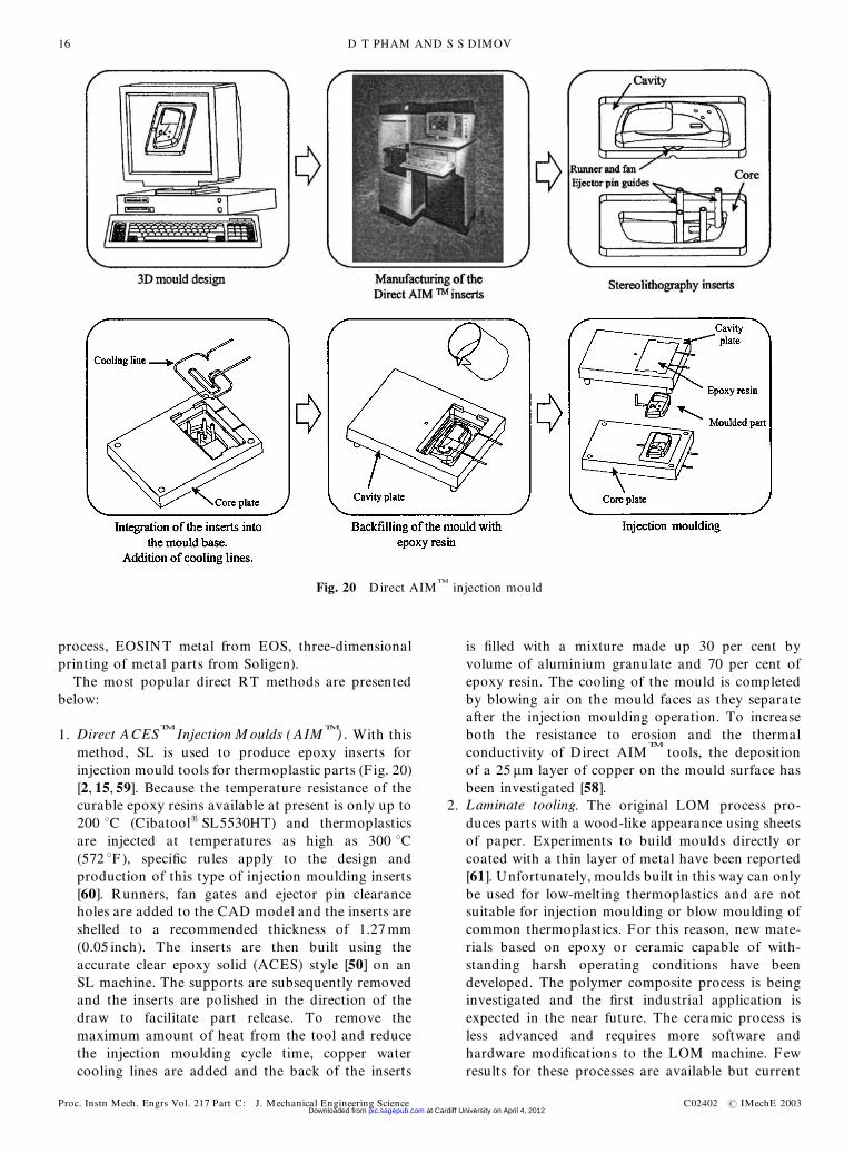
1. Direct ACESTM
Injection M oulds ( AIMTM
) . With thismethod, SL is used to produce epoxy inserts forinjection mould tools for thermoplastic parts (F ig. 20)[2, 15, 59]. Because the temperature resistance of thecurable epoxy resins available at present is only up to200 8C (Cibatool1 SL5530HT) and thermoplasticsare injected at temperatures as high as 300 8C(572 8F), speci�c rules apply to the design andproduction of this type of injection moulding inserts[60]. Runners, fan gates and ejector pin clearanceholes are added to the CAD model and the inserts areshelled to a recommended thickness of 1.27 mm(0.05 inch). The inserts are then built using theaccurate clear epoxy solid (ACES) style [50] on anSL machine. The supports are subsequently removedand the inserts are polished in the direction of thedraw to facilitate part release. To remove themaximum amount of heat from the tool and reducethe injection moulding cycle time, copper watercooling lines are added and the back of the inserts
is �lled with a mixture made up 30 per cent byvolume of aluminium granulate and 70 per cent ofepoxy resin. The cooling of the mould is completedby blowing air on the mould faces as they separateafter the injection moulding operation. To increaseboth the resistance to erosion and the thermalconductivity of Direct AIM
TM
tools, the depositionof a 25 mm layer of copper on the mould surface hasbeen investigated [58].
2. Laminate tooling. The original LOM process pro-duces parts with a wood-like appearance using sheetsof paper. Experiments to build moulds directly orcoated with a thin layer of metal have been reported[61]. Unfortunately, moulds built in this way can onlybe used for low-melting thermoplastics and are notsuitable for injection moulding or blow moulding ofcommon thermoplastics. For this reason, new mate-rials based on epoxy or ceramic capable of with-standing harsh operating conditions have beendeveloped. The polymer composite process is beinginvestigated and the �rst industrial application isexpected in the near future. The ceramic process isless advanced and requires more software andhardware modi�cations to the LOM machine. Fewresults for these processes are available but current
Fig. 20 Direct AIMTM
injection mould
D T PHAM AND S S DIMOV16
Proc. Instn Mech. Engrs Vol. 217 Part C: J. Mechanical Engineering Science C02402 # IMechE 2003 at Cardiff University on April 4, 2012pic.sagepub.comDownloaded from
indications are promising. In addition, attempts havebeen made to use unbonded laminate tooling forpressure die casting [62]. In this case, the prototypetools are fabricated by clamping together laser-cutpro�les in tool steel sheets.
3. RapidToolTM
process. This process employs SLS tobuild tooling inserts. The latest materials developedfor the RapidTool process of producing metal partsby SLS are LaserForm
TM
and copper polyamide(PA).Each of these materials requires different processingtechniques:(a) LaserForm
TM
[63]. This is a powder made of 420stainless-steel-based particles, coated with athermoplastic binder. The processing of Laser-Form can be broken down into two main stages[63]. During the �rst stage (the ‘green’ stage),tooling inserts are built layer by layer throughfusion of the binder in an SLS machine. In thesecond stage (oven cycle), the green part isconverted into a fully dense metal part byin�ltration with molten bronze. During theoven cycle, between 450 and 650 8C the polymerevaporates and at 700 8C the sintering of theremaining steel powder begins. Then the insertsare heated up to 1070 8C where bronze in�ltra-tion occurs driven by capillary action. To avoidoxidation of the steel surfaces, all processing isdone in a nitrogen atmosphere. The �nal Laser-Form inserts are 60 per cent stainless steel and 40per cent bronze fully dense parts, which can be�nished by any technique, including surfacegrinding, milling, drilling, wire erosion, EDM,polishing and surface plating.
(b) Copper PA [64]. This is a metal–plastic compositedesigned for short-run tooling applications invol-ving several hundred parts (100–400 parts) fromcommon plastics. At the CAD stage, the insertsare shelled and cooling lines, ejector pin guides,gates and runners are included in the design to bebuilt directly during the SLS process. No furnacecycle is required and un�nished tool inserts canbe produced in a day. Only subsequent �nishingis necessary before integration of the inserts inthe tool base. This includes sealing of the insertsurfaces with epoxy, �nishing them with sand-paper and �nally backing up the shell insertswith a metal alloy. The cycle times of mouldsemploying copper PA inserts are similar to thosefor metal tooling.
Development efforts have been directed towardsinsert design optimization [2], increasing heat transferrates by producing inserts with conformal coolingchannels [65] and re�ning insert �nishing techniques[2].
4. SandFormTM
tooling. SandFormTM
zirconium andsilicon materials can be used to build moulds andcores directly from three-dimensional CAD data
employing the SLS process [2]. The sand mouldsand cores produced are of equivalent accuracy andhave properties that are identical to those of mouldsand cores fabricated with conventional methods.SandForm
TM
moulds and cores can be used for low-pressure sand casting.
5. EOS DirectToolTM
process [66]. This process usesproprietary metal powders that are selectively sin-tered in a specially developed machine. The sinteredparts are porous and usually must undergo in�ltra-tion with an epoxy resin in order to increase theirstrength [66]. After in�ltration, further polishing ofthe part surfaces is possible to achieve the qualityrequired for injection moulding inserts. The Direct-Tool
TM
process is mainly utilized for rapidly produ-cing complex inserts, the surfaces of which cannot bemachined directly. The process is a viable alternativefor prototype and pre-production tooling applica-tions, requiring the manufacture of up to a fewthousand parts in common engineering plastics.
6. Direct metal tooling using 3DP. This RT process uses3DP to build tooling inserts in a range of materialsincluding stainless steel, tungsten and tungstencarbide. The process allows the fabrication of partswith overhangs, undercuts and internal volumes aslong as there is an escape route for the unused loosepowder. The production of metal parts includes thefollowing steps:(a) building the parts by combining powder and
binder employing the 3DP process;(b) sintering the printed parts in a furnace to increase
their strength;(c) in�ltration of the sintered parts with a low
melting point alloy to produce fully dense parts.The 3DP process can be easily adapted for produc-tion of parts in a variety of material systems, e.g.metallic/ceramic compositions with novel materialproperties [24, 67].
7. Topographic shape formation ( TSF) . This process isvery similar to 3DP. This technology is usedprimarily for the rapid production of moulds. Partsare built by successive layering of a silica powder andselective spraying of paraf�n wax from an X–Y –Zcontrolled nozzle. The wax binds the powder to forma new cross-section of the part and also partiallymelts the previous layer to ensure good adhesion.Once a part is completed, it is sanded, coated in waxand then employed as a mould for the customer’scomponent. Materials in use include concrete,�breglass and expanding foam [68].
Direct methods for tool production reduce the totalproduction time and the inaccuracies introduced byintermediate replication stages. The restricted range ofmaterials available is still the most severe drawback ofdirect tooling methods, but materials are continuallyimproving and new materials are regularly becoming
RP AND RT—THE KEY ENABLERS FOR RAPID MANUFACTURING 17
C02402 # IMechE 2003 Proc. Instn Mech. Engrs Vol. 217 Part C: J. Mechanical Engineering Science at Cardiff University on April 4, 2012pic.sagepub.comDownloaded from
available. Special attention should be paid to the speci�cdesign and �nishing requirements of RT inserts becausethese aspects critically affect the capabilities of theprocess [69, 70]. A promising direction for furtherimprovement of direct tooling methods is to combinetheir capabilities with those of traditional toolingmethods. In this way, the application area of directtooling methods can be extended signi�cantly.
5 APPLICATIONS OF RAPID TOOLINGTECHNOLOGY
The introduction of RT technology has enabled proto-type, pre-production and in some cases full productiontooling to be fabricated within signi�cantly reduced timeframes. A sound understanding of the capabilities andlimitations of RT processes is essential in order toimplement the technology successfully.
This section presents three examples illustrating theapplication of the RapidTool
TM
process, one of the mostdeveloped direct RT methods, to aluminium gravity diecasting, plastics injection moulding and production ofmetal parts:
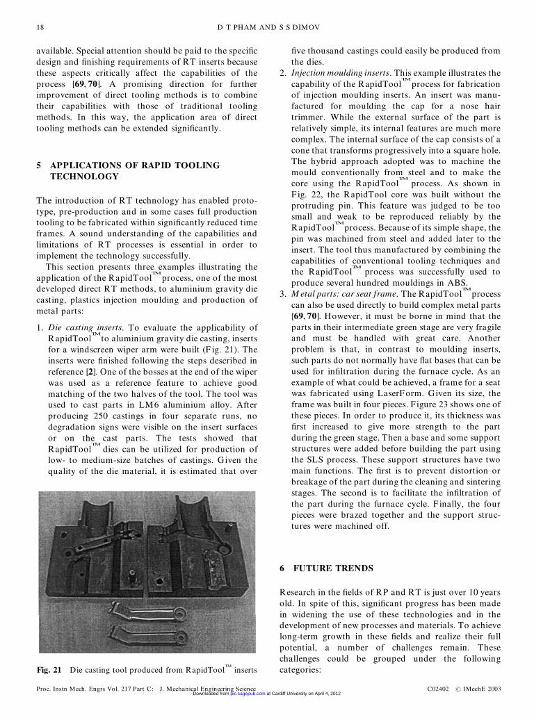
1. Die casting inserts. To evaluate the applicability ofRapidTool
TM
to aluminium gravity die casting, insertsfor a windscreen wiper arm were built (F ig. 21). Theinserts were �nished following the steps described inreference [2]. One of the bosses at the end of the wiperwas used as a reference feature to achieve goodmatching of the two halves of the tool. The tool wasused to cast parts in LM6 aluminium alloy. Afterproducing 250 castings in four separate runs, nodegradation signs were visible on the insert surfacesor on the cast parts. The tests showed thatRapidTool
TM
dies can be utilized for production oflow- to medium-size batches of castings. Given thequality of the die material, it is estimated that over
�ve thousand castings could easily be produced fromthe dies.
2. Injection moulding inserts. This example illustrates thecapability of the RapidTool
TM
process for fabricationof injection moulding inserts. An insert was manu-factured for moulding the cap for a nose hairtrimmer. While the external surface of the part isrelatively simple, its internal features are much morecomplex. The internal surface of the cap consists of acone that transforms progressively into a square hole.The hybrid approach adopted was to machine themould conventionally from steel and to make thecore using the RapidTool
TM
process. As shown inF ig. 22, the RapidTool core was built without theprotruding pin. This feature was judged to be toosmall and weak to be reproduced reliably by theRapidTool
TM
process. Because of its simple shape, thepin was machined from steel and added later to theinsert. The tool thus manufactured by combining thecapabilities of conventional tooling techniques andthe RapidTool
TM
process was successfully used toproduce several hundred mouldings in ABS.
3. M etal parts: car seat frame. The RapidToolTM
processcan also be used directly to build complex metal parts[69, 70]. However, it must be borne in mind that theparts in their intermediate green stage are very fragileand must be handled with great care. Anotherproblem is that, in contrast to moulding inserts,such parts do not normally have �at bases that can beused for in�ltration during the furnace cycle. As anexample of what could be achieved, a frame for a seatwas fabricated using LaserForm. Given its size, theframe was built in four pieces. Figure 23 shows one ofthese pieces. In order to produce it, its thickness was�rst increased to give more strength to the partduring the green stage. Then a base and some supportstructures were added before building the part usingthe SLS process. These support structures have twomain functions. The �rst is to prevent distortion orbreakage of the part during the cleaning and sinteringstages. The second is to facilitate the in�ltration ofthe part during the furnace cycle. F inally, the fourpieces were brazed together and the support struc-tures were machined off.
6 FUTURE TRENDS
Research in the �elds of RP and RT is just over 10 yearsold. In spite of this, signi�cant progress has been madein widening the use of these technologies and in thedevelopment of new processes and materials. To achievelong-term growth in these �elds and realize their fullpotential, a number of challenges remain. Thesechallenges could be grouped under the followingcategories:Fig. 21 Die casting tool produced from RapidTool
TM
inserts
D T PHAM AND S S DIMOV18
Proc. Instn Mech. Engrs Vol. 217 Part C: J. Mechanical Engineering Science C02402 # IMechE 2003 at Cardiff University on April 4, 2012pic.sagepub.comDownloaded from
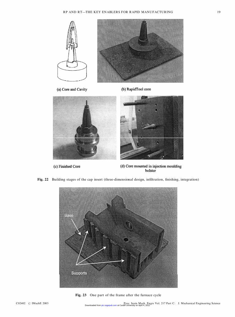
Fig. 22 Building stages of the cap insert (three-dimensional design, in�ltration, �nishing, integration)
Fig. 23 One part of the frame after the furnace cycle
RP AND RT—THE KEY ENABLERS FOR RAPID MANUFACTURING 19
C02402 # IMechE 2003 Proc. Instn Mech. Engrs Vol. 217 Part C: J. Mechanical Engineering Science at Cardiff University on April 4, 2012pic.sagepub.comDownloaded from
1. Productivity/cost of RP machines. To bene�t trulyfrom the ‘direct’ fabrication capabilities of RPprocesses, especially when the serial production ofparts is targeted, their productivity should beincreased and machine costs reduced signi�cantly.Currently, there are two main approaches to addres-sing these issues. With the �rst approach, productiv-ity is raised by increasing the number of channelsused for data transfer (multiple one-dimensionalchannels) without modifying the working principlesof a process. The second approach is to develop anew generation of RP machines that are speciallydesigned for serial production and employ newmechanisms for data transfer (multiple/arrays ofone-dimensional channels or two-dimensional chan-nels) and/or new physical principles. It is expectedthat long-term growth in the RP industry will comefrom applications that are impossible/very dif�cult,costly and time consuming to implement withconventional manufacturing techniques. Therefore,new RP machines should address the speci�crequirements of these applications. For example,these new machines should allow improved accuracyand surface �nish of RP parts, multi-axis depositionof material, direct building of multi-componentassemblies [71], fabrication of materially gradedstructures (in density and composition) and manu-facture of mesoscopic components and devices.Furthermore, it is expected that wider use of RPmachines for rapid manufacturing would lead toreduction of their cost.
2. M aterials. One of the main limitations of RPprocesses is the limited variety of materials and theirproperties, and also their relatively high cost.Signi�cant research efforts are focused on thedevelopment of a broader range of materials thatsimulate very closely the properties of the mostcommonly used engineering plastics. In particular,much research is being conducted on the develop-ment of new materials with high rigidity, high impactstrength and high tensile elongation at breaking.Also, a range of materials for fabrication of invest-ment casting patterns with low ash content, highimpact strength and good surface �nish are currentlyunder development. Recently, the fabrication ofmulti-materials and heterogeneous objects hasattracted the attention of the research community.This is quite understandable because RP is well suitedto building such objects. Functionally gradientcomponents could be manufactured from differentconstituent materials exhibiting continuously varyingcomposition and/or microstructure. Developments inthis area will make possible the fabrication of objectswith multiple and con�icting functionality. Progressin the area is directly linked with the development ofnew CAD tools that are suitable for designingheterogeneous objects.
3. Process planning. Although process plans for buildingcomplex RP parts are reduced to containing onlythree operations (these usually being building parts,inspection and �nishing, which can include painting)compared to the many steps required by conventionalmaterial removal processes, the process planningtasks associated with layer manufacturing requirespecial attention. These tasks include selecting thepart orientation, identifying the support structuresneeded, slicing and deposition path planning and thespeci�cation of process parameters. Existingapproaches to addressing these problems fall intotwo categories: algorithmic and decision-supportsolutions [72]. The algorithmic approach relies ongeometrical reasoning mechanisms to �nd solutionsfor these tasks. For example, this approach is used todetermine the part orientation in respect of someuser-de�ned criteria (minimization of the supportstructures required, avoidance of trapped volumes,improving part quality and engineering properties),to study the in�uence of different deposition patternsand process parameters on part properties, to identifyoverhanging features requiring support structuresutilizing STL �le facets, solid models or slice data,and to develop new techniques for slicing (adaptiveslicing and slicing of heterogeneous objects). Thesecond approach employs decision-support methodsto perform tasks that require quantifying the trade-offs between competing goals. Such process planningmethods employ multi-criteria optimization techni-ques, analytical models and heuristics [73]. Withincreases in part complexity and the wide range ofavailable RP materials and RP machines, there is aneed for more advanced process planning tools, inparticular tools that could relate process variables topart quality characteristics and address the process-speci�c requirements associated with the fabricationof parts from heterogeneous materials.
4. RP data formats and design tools. The stereolitho-graphy (STL) format was introduced in the earlyyears of RP technology and is considered a de factostandard for interfacing CAD and RP systems. TheSTL format has a number of drawbacks [74] that areinherent in the representation scheme employed. Theuse of other standard formats for product dataexchange such as IGES, HPGL, STEP and VRMLhave been considered in place of STL, but asproblems remain these alternative formats are notwidely accepted. Work on the development of newformats continues in order to address the growingrequirements of RP and RT applications for moreprecise methods of data representation. Also, inrecent years, with the emergence of RP processes forfabrication of heterogeneous objects, there is anincreasing interest within the research community indeveloping new CAD tools that enable objects withvarying material composition and/or microstructure
D T PHAM AND S S DIMOV20
Proc. Instn Mech. Engrs Vol. 217 Part C: J. Mechanical Engineering Science C02402 # IMechE 2003 at Cardiff University on April 4, 2012pic.sagepub.comDownloaded from
to be designed [72]. Currently, a number of CADsystems for constructing such objects are underdevelopment employing voxel-based methods [75],generalized cellular decomposition [76], �nite elementbased methods [76, 77] and constructive methods [78].As already mentioned, advances in this area aredirectly linked to research and development intechnologies capable of producing materially gradedstructures.
7 CONCLUSIONS
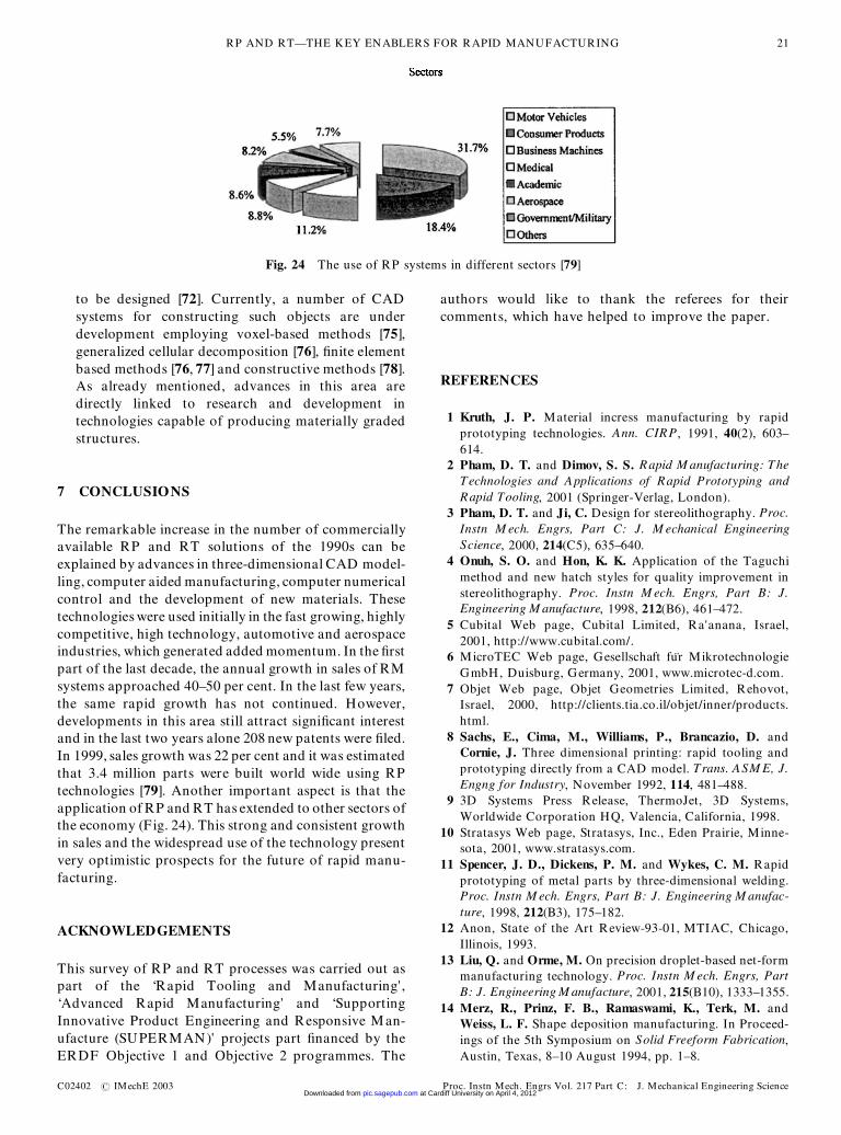
The remarkable increase in the number of commerciallyavailable RP and RT solutions of the 1990s can beexplained by advances in three-dimensional CAD model-ling, computer aided manufacturing, computer numericalcontrol and the development of new materials. Thesetechnologies were used initially in the fast growing, highlycompetitive, high technology, automotive and aerospaceindustries, which generated added momentum. In the �rstpart of the last decade, the annual growth in sales of RMsystems approached 40–50 per cent. In the last few years,the same rapid growth has not continued. However,developments in this area still attract signi�cant interestand in the last two years alone 208 new patents were �led.In 1999, sales growth was 22 per cent and it was estimatedthat 3.4 million parts were built world wide using RPtechnologies [79]. Another important aspect is that theapplication of RP and RT has extended to other sectors ofthe economy (Fig. 24). This strong and consistent growthin sales and the widespread use of the technology presentvery optimistic prospects for the future of rapid manu-facturing.
ACKNOWLEDGEMENTS
This survey of RP and RT processes was carried out aspart of the ‘Rapid Tooling and Manufacturing’,‘Advanced Rapid Manufacturing’ and ‘SupportingInnovative Product Engineering and Responsive Man-ufacture (SUPERMAN)’ projects part �nanced by theERDF Objective 1 and Objective 2 programmes. The
authors would like to thank the referees for theircomments, which have helped to improve the paper.
REFERENCES
1 Kruth, J. P. Material incress manufacturing by rapidprototyping technologies. Ann. CIRP, 1991, 40(2), 603–614.
2 Pham, D. T. and Dimov, S. S. Rapid M anufacturing: TheTechnologies and Applications of Rapid Prototyping andRapid Tooling, 2001 (Springer-Verlag, London).
3 Pham, D. T. and Ji, C. Design for stereolithography. Proc.Instn M ech. Engrs, Part C: J. M echanical EngineeringScience, 2000, 214(C5), 635–640.
4 Onuh, S. O. and Hon, K. K. Application of the Taguchimethod and new hatch styles for quality improvement instereolithography. Proc. Instn M ech. Engrs, Part B: J.Engineering M anufacture, 1998, 212(B6), 461–472.
5 Cubital Web page, Cubital Limited, Ra’anana, Israel,2001, http://www.cubital.com/.
6 MicroTEC Web page, Gesellschaft fur MikrotechnologieGmbH, Duisburg, Germany, 2001, www.microtec-d.com.
7 Objet Web page, Objet Geometries Limited, Rehovot,Israel, 2000, http://clients.tia.co.il/objet/inner/products.html.
8 Sachs, E., Cima, M., Williams, P., Brancazio, D. andCornie, J. Three dimensional printing: rapid tooling andprototyping directly from a CAD model. Trans. ASM E, J.Engng for Industry, November 1992, 114, 481–488.
9 3D Systems Press Release, ThermoJet, 3D Systems,Worldwide Corporation HQ, Valencia, California, 1998.
10 Stratasys Web page, Stratasys, Inc., Eden Prairie, Minne-sota, 2001, www.stratasys.com.
11 Spencer, J. D., Dickens, P. M. and Wykes, C. M. Rapidprototyping of metal parts by three-dimensional welding.Proc. Instn M ech. Engrs, Part B: J. Engineering M anufac-ture, 1998, 212(B3), 175–182.
12 Anon, State of the Art Review-93-01, MTIAC, Chicago,Illinois, 1993.
13 Liu, Q. and Orme, M. On precision droplet-based net-formmanufacturing technology. Proc. Instn M ech. Engrs, PartB: J. Engineering M anufacture, 2001, 215(B10), 1333–1355.
14 Merz, R., Prinz, F. B., Ramaswami, K., Terk, M. andWeiss, L. F. Shape deposition manufacturing. In Proceed-ings of the 5th Symposium on Solid Freeform Fabrication,Austin, Texas, 8–10 August 1994, pp. 1–8.
Fig. 24 The use of RP systems in different sectors [79]
RP AND RT—THE KEY ENABLERS FOR RAPID MANUFACTURING 21
C02402 # IMechE 2003 Proc. Instn Mech. Engrs Vol. 217 Part C: J. Mechanical Engineering Science at Cardiff University on April 4, 2012pic.sagepub.comDownloaded from

15 Pham, D. T., Dimov, S. S. and Lacan, F. Selective lasersintering: applications and technological capabilities. Proc.Instn M ech. Engrs, Part B: J. Engineering M anufacture,1999, 213(B5), 435–449.
16 Pham, D. T. and Wang, X. Prediction and reduction ofbuild times for the selective laser sintering process. Proc.Instn M ech. Engrs, Part B: J. Engineering M anufacture,2000, 214(B6), 425–430.
17 Childs, T. H., Berzins, M., Ryder, G. R. and Tontowi, A.Selective laser sintering of an amorphous polymer—simulations and experiments. Proc. Instn M ech. Engrs,Part B: J. Engineering M anufacture, 1999, 213(B4), 333–349.
18 Kathuria, Y. P. Metal rapid prototyping via a lasergenerating/selective sintering process. Proc. Instn M ech.Engrs, Part B: J. Engineering M anufacture, 2000, 214(B1),1–9.
19 Optomec Web page, Optomec Design Company, Albu-querque, New Mexico, 2000, http://www.optomec.com/.
20 POM Web page, Precision Optical Manufacturing, Ply-mouth, Michigan, 2001, www.pom.net.
21 AeroMet Web page, AeroMet Corporation, Eden Prairie,Minnesota, 2001, www.aerometcorp.com.
22 Texas Instruments Web page, Digital Light Processing,Texas Instruments, 2001, www.dlp.com.
23 SRI Web page, SRI International, Menlo Park, California,2001, http://pguerit.sri.com/SriWeb/srihome.html.
24 MIT Web page, MIT, Three Dimensional Printing Group,1999, http://me.mit.edu/groups/tdp/.
25 Sachs, E., Cornie, J., Brancazio, D., Bredt, J., Curodeau,A., Fan, T., Khanuja, S., Lauder, A., Lee, J. and Michaels,S. Three dimensional printing: the physics and implicationsof additive manufacturing. Ann. CIRP, 1993, 42(1), 257–260.
26 Helisys Web page, Helisys, Inc., Torrance, California,2000, http://helisys.com/.
27 Karunakaran, K. P., Dibbi, S., Shanmuganathan, P. V.,Raju, D. S. and Kakaraparti, S. Optimal stock removal inLom-Rp. Proc. Instn M ech. Engrs, Part B: J. EngineeringM anufacture, 2000, 214(B10), 947–951.
28 KIRA Web page, KIRA Corporation, Aichi, Japan, 2000,www.kiracorp.co.jp.
29 Corbel, S., Allanic, A. L., Schaeffer, P. and Andre, J. C.Computer-aided manufacture of three-dimensional objectsby laser space-resolved photopolymerization. J. Intell.Robotic Systems, 1994, 9, 310–312.
30 Song, Y. and Chen, Y. H. Feature-based robot machiningfor rapid prototyping. Proc. Instn M ech. Engrs, Part B: J.Engineering M anufacture, 1999, 213(B5), 451–459.
31 Chichkov, B. N., Momma, C., Nolte, S., von Alvensleben, F.and Tunnermann, A. Femtosecond, picosecond and nano-second laser ablation of solids. Appl. Physics, 1996, A63,109–115.
32 Momma, C., Nolte, S., Chichkov, B. N., von Alvensleben, F.and Tunnermann, A. Precise laser ablation with ultrashortpulses. Appl. Surf. Sci., 1997, 109–110, 15–19.
33 Pham, D. T., Dimov, S. S., Petkov, P. P. and Petkov, S. P.Laser milling. Proc. Instn M ech. Engrs, Part B: J.Engineering M anufacture, 2002, 216(B5), 657–667.
34 Shirk, M. D. and Molian, P. A. A review of ultrashortpulsed laser ablation of materials. J. Laser Applic., 1998,10(1), 18–28.
35 Kautek, W. and Kruger, J. Femtosecond pulse laserablation of metallic, semiconducting, ceramic and biologi-cal materials. Proc. SPIE, 1994, 2207, 600–610.
36 Preuss, S., Demchuk, A. and Stuke, M. Sub-picosecond UVlaser ablation of metals. Appl. Physics, 1995, A61, 33–37.
37 von der Linde, D. and Sokolowski-Tinten, K. The physicalmechanisms of short-pulse laser ablation. Appl. Surf. Sci.,2000, 154–155, 1–10.
38 Toenshoff, H. K., von Alvensleben, F., Ostendorf, A.,Willmann, G. and Wagner, T. Precision machining usingUV and ultrashort pulse laser. Proc. SPIE, 1999, 3680,536–545.
39 Mendes, M., Oliveira, V., Vilar, R., Beinhorn, F., Ihlemann,J. and Conde, O. XeCl laser ablation of Al2O3–TiCceramics. Appl. Surf. Sci., 2000, 154–155, 29–33.
40 Pham, D. T., Dimov, S. S., Petkov, P. P. and Petkov, S. P.Rapid manufacturing of ceramic parts. In Proceedings of17th National Conference on M anufacturing Research,2001, pp. 211–216 (Professional Engineering Publishing,Bury St Edmunds and London).
41 van de Crommert, S., Seitz, S., Esser, K. K. and McAlea, K.Sand, die and investment cast parts via the SLS selectivelaser sintering process. DTM GmbH, Hilden, Germany,1997.
42 DTM Corporation, CastForm: Guide to M aterials, 1998(DTM Corporation, Austin, Texas).
43 Anatomics Case S tudies, 2000 (Anatomics Pty Limited,Queensland, Australia), http://glacier.qmi.asn.au:80/anatomics/.
44 D’Urso, P. S., Atkinson, R. L., Lanigan, M. W., Earwaker,W. J., Bruce, I. J., Holmes, A., Barker, T. M., Effeney, D.J. and Thompson, R. G. Stereolithographic biomodelling incraniofacial surgery. Br. J. Plastic Surgery, 1998, 51(7),522–530.
45 D’Urso, P. S. and Redmond, M. J. Method for theresection of cranial tumours and skull reconstruction. Br.J. Neurosurgery, 2000, 4(6), 555–559.
46 D’Urso, P. S., Barker, T. M., Earwaker, W. J., Bruce, I. J.,Atkinson, R. L., Lanigan, M. W., Arvier, J. F. and Effeney,D. J. Stereolithographic biomodelling in cranio-maxillo-facial surgery: a prospective trial. J. Cranio-maxillofacialSurgery, 1999, 27, 30–37.
47 Materialise Product Information, Mimics software,Materialise, Leuven, Belgium, 2000, http://www.materialise.be/.
48 CALM Project F inal Report, University of CentralLancashire, Preston, 1998, http://www.uclan.ac.uk/clt/calm/overview.htm.
49 Gatrzen, J., Lingens, H., Gebhardt, A. and Schwarz, C.Optimisation using THESA. In Prototyping TechnologyInternational ’98, 1998, pp. 36–38 (UK and InternationalPress, Surrey).
50 Jacobs, P. F. Stereolithography and other RP&M technol-ogies. Society of Manufacturing Engineers–AmericanSociety of Mechanical Engineers, 1996.
51 3D Systems Newsletter: The Edge, Summer 1994 (3DSystems, Valencia, California).
52 Raymond, N. C. and Thomas, V. J. A comparison of rapidprototyping techniques used for wind tunnel modelfabrication. Rapid Prototyping J., 1998, 4(4), 185–196.
53 Pham, D. T., Dimov, S. S. and Lacan, F. Techniques for�rm tooling using rapid prototyping. Proc. Instn M ech.
D T PHAM AND S S DIMOV22
Proc. Instn Mech. Engrs Vol. 217 Part C: J. Mechanical Engineering Science C02402 # IMechE 2003 at Cardiff University on April 4, 2012pic.sagepub.comDownloaded from

Engrs, Part B: J. Engineering M anufacture, 1998, 212(B4),269–277.
54 Mueller, T. Stereolithography-based prototyping: casehistories of application in product development. In IEEETechnical Application and Conference Workshops, Port-land, Oregon, 10 October 1995, pp. 305–309.
55 Dickens, P. M. Rapid tooling: a review of the alternatives.Rapid News, 1996, 4(5), 54–60.
56 Schaer, L. Spin-casting fully functional metal and plasticparts from stereolithography models. In Proceedings of the6th International Conference on Rapid Prototyping, Day-ton, Ohio, 1995, Vol. 27, pp. 217–235.
57 Mosemiller, L. and Schaer, L. Combining RP andspin-casting. In Prototyping Technology International’97, 1997, pp. 242–246 (UK and International Press,Surrey).
58 Jacobs, P. F. Recent advances in rapid tooling fromstereolithography. White Paper, 1996 (3D Systems, Valen-cia, California).
59 Hopkinson, N. and Dickens, P. M. Using stereolithographytools for injection moulding: research into tensile toolfailure and unexpected bene�ts of the process. Proc. InstnM ech. Engrs, Part B: J. Engineering M anufacture, 2000,214(B10), 891–899.
60 Decelles, P. and Barritt, M. Direct AIMTM
PrototypeTooling, Procedural Guide, 1996 (3D Systems, Valencia,California).
61 Pak, S. S., Klosterman, D. A., Priore, B., Chartoff, R. P.and Tolin, D. R. Tooling and low volume manufacturethrough laminated object manufacturing. In PrototypingTechnology International ’97, 1997, pp. 184–188 (UK andInternational Press, Surrey).
62 Soar, R. and Dickens, P. M. Design limits of unbondedlaminate tooling for pressure die-casting. Proc. Instn M ech.Engrs, Part B: J. Engineering M anufacture, 2001, 215(B4),531–543.
63 DTM Product Information—LaserFormTM
, 2000 (DTMGmbH, Hilden, Germany); DTM Product Information,Copper Polyamide M old Insets for Plastic Injection M old-ing, June 1998 (DTM Corporation, Austin, Texas).
64 Dalgarno, K. W. and Stewart, T. D. Manufacture ofproduction injection mould tooling incorporating confor-mal cooling channels via indirect selective laser sintering.Proc. Instn M ech. Engrs, Part B: J. Engineering M anufac-ture, 2001, 215(B10), 1323–1332.
65 Fritz, E. Laser-sintering on its way up. In PrototypingTechnology International ’98, 1998, pp. 186–189 (UK andInternational Press, Surrey).
66 Sachs, E., Guo, H., Wylonis, E., Serdy, J., Brancazio, D.,Rynerson, M., Cima, M. and Allen, S. Injection moldingtooling by 3D printing. In Prototyping Technology Inter-national ’97, 1997, pp. 322–325 (UK and InternationalPress, Surrey).
67 Formus Web page, Formus, San Jose, California, 2000,www.formus.com.
68 Shi, D. and Gibson, I. Improving surface quality ofselective laser sintered rapid prototype parts using robotic�nishing. Proc. Instn M ech. Engrs, Part B: J. EngineeringM anufacture, 2000, 214(B3), 197–203.
69 Dimov, S. S., Pham, D. T., Lacan, F. and Dotchev, K. D.Rapid tooling applications of the selective laser sinteringprocess. Int. J. Assembly Technol. M anagmt, 2001, 21, 107–116.
70 Volpato, N., Childs, T. H. C., Stewart, T. D. and Watson,P. Indirect selective laser sintering of metal parts withoverhung features. Proc. Instn M ech. Engrs, Part B: J.Engineering M anufacture, 2001, 215(B6), 873–876.
71 Birnnard, M. Design by Composition for Rapid Prototyping,1st edition, 1999 (Kluwer Academic, Dordrecht, TheNetherlands).
72 Dutta, D., Prinz, F. B., Rosen, D. and Weiss, L. Layermanufacturing: current status and future trends. Trans.ASM E, J. Computing and Inf. Sci. Engng, 2001, 1, 60–71.
73 West, A. P., Sambu, S. and Rosen, D. W. A processplanning method for improving build performance instereolithography. Computer-Aided Des., 2001, 33(1), 65–80.
74 Kumar, V. and Dutta, D. An assessment of data formats forlayer manufacturing. Adv. Engng Software, 1997, 28(3),151–164.
75 Wu, Z. W., Soon, S. H. and Feng, L. NUBS-based volumemodelling. In International Workshop on Volume Graphics,Swansea, 1999, pp. 321–330.
76 Jackson, T., Liu, H., Patrikalakis, N. M., Sachs, E. M. andCima, M. J. M odelling and Designing Functionally GradedM aterial Components for Fabrication with Local Composi-tion Control, M aterials and Design, 1999, Special Issue,(Elsevier Science, Amsterdam, The Netherlands).
77 Kumar, V. A. and Wood, A. Representation and design ofheterogeneous components. In Proceedings of SFF Con-ference, Austin, Texas, 1999.
78 Bhashyam, S., Shin, K. H. and Dutta, D. An integratedCAD system for design of heterogeneous objects. RapidPrototyping J., 2000, 6(2), 107–118.
79 Wohlers, T. Wohlers Report 2000: executive summary.Time-Compression Technologies, 2000, 8(4), 29–31.
RP AND RT—THE KEY ENABLERS FOR RAPID MANUFACTURING 23
C02402 # IMechE 2003 Proc. Instn Mech. Engrs Vol. 217 Part C: J. Mechanical Engineering Science at Cardiff University on April 4, 2012pic.sagepub.comDownloaded from