product catalog - distribuidor exclusivo tranercclimas.com/literaturas-productos/chiller rtwd rtud -...
TRANSCRIPT
Series R™ Helical Rotary Liquid Chillers
80-250 Nominal Tons Model RTWD Water-Cooled80-250 Nominal Tons Model RTUD CondenserlessMade in USA (60 Hz)
October 2012 RLC-PRC029-EN
Product Catalog
© 2012 Trane All rights reserved RLC-PRC029-EN
Introduction
To meet a wide range of applications in the 75-240 ton water-cooled market, Trane is proud tointroduce the model RTWD helical-rotary liquid chiller. To meet a wide range of applications in the70-200 ton condenserless market, Trane is offering the RTUD condenserless chiller. Theintroduction of this next-generation chiller is an exciting step forward in application versatility, easeof installation, control precision, reliability, energy-efficiency, and operational cost-effectiveness.The new chiller is designed to deliver proven Series R performance, plus all the benefits of anadvanced heat transfer design with two low-speed, direct-drive compressors.
Important Design Advances and New Features
• Higher full-load energy efficiency that meets ASHRAE 90.1 and reduces both operating and life-cycle costs.
• Variable evaporator flow compensation for improved control stability with energy savingvariable flow applications.
• Single chiller time of day scheduling communication option for easier control of small jobs.
• Dual independent refrigerant circuits.
• HFC-134a optimized design.
The industrial-grade design of the Series R helical-rotary chiller is ideal for both industrial andcommercial markets, in applications such as office buildings, hospitals, schools, retail buildings,and industrial facilities. The reliable compressors, wide operating temperature range, advancedcontrols, electronic expansion valve, short anti-recycle timers, and industry-leading efficienciesmean that this latest Trane Series R chiller is the perfect choice for tight temperature control inalmost any application temperatures, and under widely varying loads.
Revision Summary
RLC-PRC029-EN (20 Oct 2012)
The following points describe the changes to this revision of the manual:
• Added seismic rating options of IBC and OSHPD, added BACnet, added Rapid Restart testing,updated revision to field wiring diagram and layout diagram, updated performance data,electrical data, lug sizes and dimensional data.

Table of Contents
RLC-PRC029-EN 3
Introduction . . . . . . . . . . . . . . . . . . . . . . . . . . . . . . . . . . . . . . . . . . . . . . . . . . . . . . . . . . . . 2
Features and Benefits . . . . . . . . . . . . . . . . . . . . . . . . . . . . . . . . . . . . . . . . . . . . . . . . . . . 4
Application Considerations . . . . . . . . . . . . . . . . . . . . . . . . . . . . . . . . . . . . . . . . . . . . . . 7
Model Number Descriptions . . . . . . . . . . . . . . . . . . . . . . . . . . . . . . . . . . . . . . . . . . . . 11
General Data . . . . . . . . . . . . . . . . . . . . . . . . . . . . . . . . . . . . . . . . . . . . . . . . . . . . . . . . . . 13
Performance Data . . . . . . . . . . . . . . . . . . . . . . . . . . . . . . . . . . . . . . . . . . . . . . . . . . . . . 21
Controls . . . . . . . . . . . . . . . . . . . . . . . . . . . . . . . . . . . . . . . . . . . . . . . . . . . . . . . . . . . . . . 35
Electrical Data . . . . . . . . . . . . . . . . . . . . . . . . . . . . . . . . . . . . . . . . . . . . . . . . . . . . . . . . . 39
Electrical Connection . . . . . . . . . . . . . . . . . . . . . . . . . . . . . . . . . . . . . . . . . . . . . . . . . . 68
Dimensions . . . . . . . . . . . . . . . . . . . . . . . . . . . . . . . . . . . . . . . . . . . . . . . . . . . . . . . . . . . 76
Mechanical Specifications . . . . . . . . . . . . . . . . . . . . . . . . . . . . . . . . . . . . . . . . . . . . . . 85

Features and Benefits
Reliability
• The Trane helical rotary compressor is a proven design resulting from years of research andthousands of test hours, including extensive testing under extraordinarily severe operatingconditions.
• Trane is the world’s largest manufacturer of large helical rotary compressors, with more than240,000 compressors installed worldwide.
• Direct drive, low-speed compressors—a simple design with only four moving parts—providesmaximum efficiency, high reliability, and low maintenance requirements.
• Suction gas-cooled motor stays at a uniformly low temperature for long motor life.
• Electronic expansion valve, with fewer moving parts than alternative valve designs, provideshighly reliable operation.
High Performance
• Advanced design enables chilled water temperature control to ±0.5°F (0.28°C) for flow changesup to 10 percent per minute, plus handling of flow changes up to 30 percent per minute forvariable flow applications.
• Two minute stop-to-start and five minute start-to-start anti-recycle timer allows tight chilledwater temperature control in constant or transient low-load applications.
• High compressor lift capabilities for use with heat recovery and waterside heat pumpapplications allows highly efficient system design with minimal operational concerns.
• Tight water temperature control extends to operation of multiple chillers in parallel or seriesconfigurations, offering further system design flexibility for maximum efficiency.
• Optional LonTalk/Tracer Summit communications interface provides excellent, trouble-freeinter operability.
Life Cycle Cost-Effectiveness
• Precise compressor rotor tip clearance ensures optimal efficiency.
• Condenser and evaporator tubes use the latest heat transfer technology for increasedefficiency.
• Electronic expansion valve enables exceptionally tight temperature control and extremely lowsuperheat, resulting in more efficient full-load and part-load operation than previouslyavailable.
• Chilled water reset based on return water temperature is standard.
• Electrical current-limiting is available as an option.
Application Versatility
• Industrial/low temperature process cooling – Excellent operating temperature range andprecise control capabilities enable tight control with single chiller or series configuration.
• Ice/thermal storage – Specifiers and operators benefit from dual setpoint control and industry-leading temperature, efficiency, and control capabilities, plus outstanding support throughpartnership with Calmac, a strong Trane partner providing proven installation examples,templates, and references that minimize design time and energy costs.
• Heat recovery – Maximum condenser temperature exceeds those of previous technologies,providing hot water and tight control that minimizes operating costs for the chilled water plantand boiler/hot water heater, while also providing consistent dehumidification.
4 RLC-PRC029-EN
Features and Benefits
• Water to water heat pump – For multi-chiller systems where there is a base or year-roundheating load the RTWD can be used as a water side heat pump by utilizing ground or surfacewater as a heat source. Leaving condenser temperature control option allows for the chiller tobe used and controlled primarily for the heat produced in the condenser.
• Dry Cooler – Allows for use with a closed condenser loop system that minimizes the potentialfor cross-contamination of the condenser loop.
• Variable primary flow – Variable evaporator flow compensation allows multi-chiller systems tovary the flow of water throughout the entire system (from the evaporator through the coolingcoils). This feature also provides additional system efficiency as the number of pumps and theflow rate in the system are reduced. Standard 2 pass or optional 3 pass evaporator allows fora wider range of flow capabilities.
• Series chiller configuration – For two-chiller systems all the system water passes through theevaporators and/or condensers of both chillers to take advantage of system efficiency gains dueto thermodynamic staging as well as downsizing the upstream chiller.
• EarthWise system – Low flow and high temperature differential installations allow for reducedpump and cooling-tower energy by decreasing the amount of water flow pumped through thesystem. This results in downsizing of all HVAC and ancillary equipment which providesinstallation and operational savings.
Simple, Economical Installation
• All units fit through standard double-width doors and most units fit through single width doors.Units are designed with bolt-together construction for disassembly to fit through smalleropenings.
• Small footprint saves valuable equipment room space and alleviates access concerns for mostretrofit jobs.
• Lightweight design simplifies rigging requirements, further reducing installation timerequirements and costs.
• Full factory refrigerant and oil charges reduce required field labor, materials, and installationcost (RTWD). An optional nitrogen charge can reduce the time and labor for projects expectingdis-assembly.
• Optional integrated forklift channels on the unit base allow for easy movement of the chiller atthe job site.
• Single or dual point power connection options simplify overall installation.
• Unit-mounted starter eliminates additional job site installation considerations and laborrequirements.
• Trane CH530 controls easily interface with Tracer Summit™,LonTalk™, or BACnet™ buildingautomation systems through single twisted-pair wire.
• Trane has conducted extensive factory testing during manufacturing, and also offers optionsfor in-person and/or documented system performance verification.
RLC-PRC029-EN 5
Features and Benefits
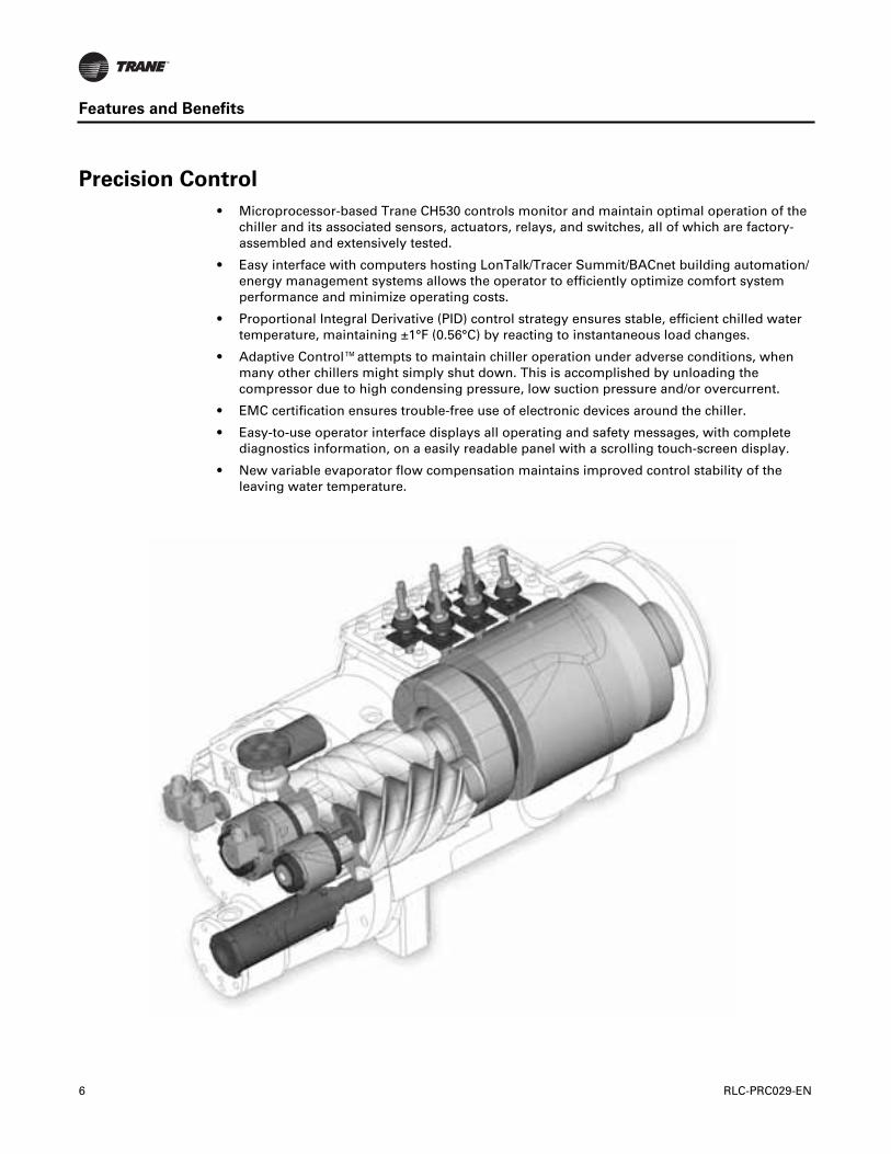
Precision Control
• Microprocessor-based Trane CH530 controls monitor and maintain optimal operation of thechiller and its associated sensors, actuators, relays, and switches, all of which are factory-assembled and extensively tested.
• Easy interface with computers hosting LonTalk/Tracer Summit/BACnet building automation/energy management systems allows the operator to efficiently optimize comfort systemperformance and minimize operating costs.
• Proportional Integral Derivative (PID) control strategy ensures stable, efficient chilled watertemperature, maintaining ±1°F (0.56°C) by reacting to instantaneous load changes.
• Adaptive Control™attempts to maintain chiller operation under adverse conditions, whenmany other chillers might simply shut down. This is accomplished by unloading thecompressor due to high condensing pressure, low suction pressure and/or overcurrent.
• EMC certification ensures trouble-free use of electronic devices around the chiller.
• Easy-to-use operator interface displays all operating and safety messages, with completediagnostics information, on a easily readable panel with a scrolling touch-screen display.
• New variable evaporator flow compensation maintains improved control stability of theleaving water temperature.
6 RLC-PRC029-EN

Application Considerations
Condenser Water Temperatures
With the model RTWD chiller, condenser head pressure control is necessary only if the unit startswith leaving condenser water temperatures below 45°F (7.2°C) or cannot rise to 55°F (12.8°C) within10 minutes.
When the application requires startup temperatures below the prescribed minimums, a variety ofsystem implementation options are available. Here are two recommended methods to control theunit operating conditions for the purpose of refrigerant differential pressure control.
1. Condenser Entering Water Temperature Control
• Tower bypass may also be a valid control method if the chiller temperature requirements canbe maintained and the loop is small.
2. Condenser Water Flow Control
• To control a 2-way or 3-way valve, select the Condenser Regulating Valve Control option forthe Trane CH530 controls. This option enables the CH530 controls to send a signal foropening and closing the valve as necessary to maintain chiller differential refrigerantpressure. The 2-way valves are available as a ship-with option.
The minimum acceptable refrigerant pressure differential between condenser and evaporator is 25psid (172.4 kPa) at all load conditions in order to ensure adequate oil circulation. The condenser andevaporator pressure differential must be 15 psid (103.4 kPa) within 2 minutes of start up. Thisequates to the condenser leaving water temperature being 17°F (9.5°C) higher than evaporatorleaving water temperature within 2 minutes of startup.
Trane Series R chillers start and operate successfully and reliably over a range of load conditionswith controlled condenser pressure. Reducing the condenser water temperature is an effectivemethod of lowering chiller power input required, but the ideal temperature for optimizing totalsystem power consumption will depend on the overall system dynamics. From a systemperspective, some improvements in chiller efficiency may be offset by the increased tower fan andpumping costs required to achieve the lower tower temperatures. Contact your local Trane systemssolution provider for more information on optimizing system performance.
Variable Evaporator Flow and Short Evaporator Water Loops
Variable evaporator flow is an energy-saving design strategy which has quickly gained acceptanceas advances in chiller and controls technology have made it possible. With its superior unloadingcompressor design and advanced Trane CH530 controls, the chiller has excellent capability tomaintain leaving water temperature control within +/-0.5°F (0.28°C), even for systems with variableevaporator flow.
Some basic rules should be followed whenever using these system design and operational savingsmethods with the chiller. The proper location of the chilled water temperature control sensor is inthe supply (outlet) water. This location allows the building to act as a buffer, and it assures a slowlychanging return water temperature. If there is insufficient water volume in the system to providean adequate buffer, temperature control can be lost, resulting in erratic system operation andexcessive compressor cycling. To ensure consistent operation and tight temperature control, thechilled water loop should be at least two minutes. If this recommendation cannot be followed, andtight leaving water temperature control is necessary, a storage tank or larger header pipe shouldbe installed to increase the volume of water in the system.
For variable primary flow applications, the rate of chilled water flow change should not exceed 10percent of design per minute to maintain +/-0.5°F (0.28°C) leaving evaporator temperature control.For applications in which system energy savings is most important and tight temperature controlis classified as +/-2°F (1.1°C), up to 30 percent change in flow per minute are possible. Flow ratesshould be maintained between the minimum and maximum allowed for any particular chillerconfiguration.
RLC-PRC029-EN 7
Application Considerations
For applications designed to operate with changes in the water flow rate, the new evaporator water-flow compensation improves the ability of the chiller to respond to increasing or decreasing waterflow. This new standard control feature works by varying the leaving evaporator temperaturecontrol gains in response to changes in evaporator water flow. By measuring the refrigerant flowin each circuit and using this value to calculate the resulting waterside temperature drop, the CH530can estimate the water flow rate through the evaporator.
With the help of a software analysis tool such as System Analyzer™, TRACE™, or EnergyPlus™,you can determine whether the anticipated energy savings justify the use of variable primary flowin a particular application. Existing constant flow chilled water systems may be relatively easilyconverted to VPF and benefit greatly from the inherent efficiency advantages.
Series Chiller Arrangements
Another energy-saving strategy is to design the system around chillers arranged in series, on theevaporator, condenser, or both. It is possible to operate a pair of chillers more efficiently in a serieschiller arrangement than in a parallel arrangement. It is also possible to achieve higher entering-to-leaving chiller differentials, which may, in turn, provide the opportunity for lower chilled waterdesign temperature, lower design flow, and resulting installation and operational cost savings(including downsizing a chiller).
The Trane screw compressor also has excellent “lift” capabilities which afford an opportunity forsavings on the evaporator and condenser water loops. Like series arrangements on the evaporator,series arrangements on the condenser may enable savings. This approach may allow reductionsin pump and tower installation and operating costs.
Maximizing system efficiency requires that the designer balance performance considerations forall system components; the best approach may or may not involve multiple chillers, or seriesarrangement of the evaporators and/or condensers. This ideal balance of design integrity withinstallation and operating cost considerations should be researched by consulting a Trane systemssolutions provider and applying the Trace™ building energy and economic analysis program.
Water-to-Water Heat Pump
The RTWD can be used as a water side heat pump by using ground or surface water as a heatsource. Leaving condenser water control option provides the ability to control the heating setpoint.Local regulation concerning limitation on minimum/maximum rejected water temperature needsto be checked before using this method.
Dry Cooler
The RTWD can be used with dry coolers. Generally this application is selected to minimize thespread of airborne contaminates associated with open tower systems. In addition, other drawbacksof cooling towers are avoided: water consumption, production of vapor, need of water treatment,etc. Another benefit of dry coolers is the ability to operate in low ambient conditions. With the useof a third party heat exchanger this design can also be used to provide free cooling to the chilledwater loop during cold weather.
8 RLC-PRC029-EN
Application Considerations
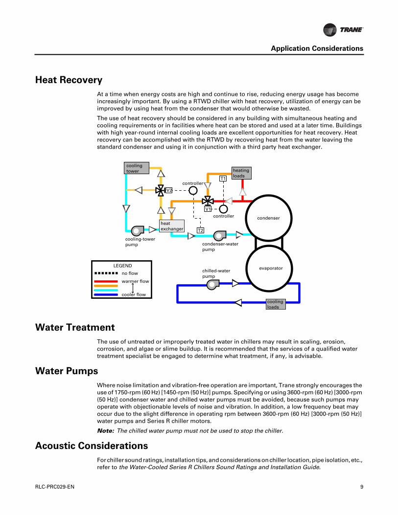
Heat Recovery
At a time when energy costs are high and continue to rise, reducing energy usage has becomeincreasingly important. By using a RTWD chiller with heat recovery, utilization of energy can beimproved by using heat from the condenser that would otherwise be wasted.
The use of heat recovery should be considered in any building with simultaneous heating andcooling requirements or in facilities where heat can be stored and used at a later time. Buildingswith high year-round internal cooling loads are excellent opportunities for heat recovery. Heatrecovery can be accomplished with the RTWD by recovering heat from the water leaving thestandard condenser and using it in conjunction with a third party heat exchanger.
Water Treatment
The use of untreated or improperly treated water in chillers may result in scaling, erosion,corrosion, and algae or slime buildup. It is recommended that the services of a qualified watertreatment specialist be engaged to determine what treatment, if any, is advisable.
Water Pumps
Where noise limitation and vibration-free operation are important, Trane strongly encourages theuse of 1750-rpm (60 Hz) [1450-rpm (50 Hz)] pumps. Specifying or using 3600-rpm (60 Hz) [3000-rpm(50 Hz)] condenser water and chilled water pumps must be avoided, because such pumps mayoperate with objectionable levels of noise and vibration. In addition, a low frequency beat mayoccur due to the slight difference in operating rpm between 3600-rpm (60 Hz) [3000-rpm (50 Hz)]water pumps and Series R chiller motors.
Note: The chilled water pump must not be used to stop the chiller.
Acoustic Considerations
For chiller sound ratings, installation tips, and considerations on chiller location, pipe isolation, etc.,refer to the Water-Cooled Series R Chillers Sound Ratings and Installation Guide.
heatexchanger
heatingloads
T1
V2
V1
T2
controller
condenser
evaporator
cooling-towerpump
coolingloads
chilled-waterpump
condenser-waterpump
cooling tower
controller
no flow
warmer flow
cooler flow
LEGEND
RLC-PRC029-EN 9

Application Considerations
Remote Condenser
The installation of a split system offers a good economic alternative to satisfy the chilled waterdemand for cooling a building, particularly in the case of new construction.
The choice of a complete Trane system, including the compressor chiller and the condenser offersthe designer, installer and owner the advantages of an optimized selection and undividedresponsibility for the design, the quality and the operation of the complete system.
The RTUD with Trane condensers has the ability to control ambients between 14°F to 125°F (-10°C-51.7°C). The RTUD with non-Trane condensers has the ability to control ambients between 5°F to125°F (-15°C-51.7°C).
Remote condensers should be located as close as possible to the chiller to ensure minimumpressure drops of discharge refrigerant. If non-Trane condensers are provided, a subcooling circuitmust be provided in order to achieve cataloged performances.
10 RLC-PRC029-EN

Model Number Descriptions
Digits 01, 02, 03, 04 – ChillerModelRTWD = Water-Cooled Series R™ ChillerRTUD = Compressor Series R Chiller
Digit 05, 06, 07 – Unit NominalTonnage070 = 70 Nominal Tons080 = 80 Nominal Tons090 = 90 Nominal Tons100 = 100 Nominal Tons110 = 110 Nominal Tons120 = 120 Nominal Tons130 = 130 Nominal Tons140 = 140 Nominal Tons150 = 150 Nominal Tons160 = 160 Nominal Tons180 = 180 Nominal Tons200 = 200 Nominal Tons220 = 220 Nominal Tons250 = 250 Nominal Tons
Digit 08 – Unit VoltageA = 200/60/3B = 230/60/3D = 380/60/3E = 400/50/3F = 460/60/3G = 575/60/3
Digit 09 – Manufacturing Plant2 = Pueblo, USA
Digit 10, 11 – Design Sequence** = First Design, etc. increment whenparts are affected for service purposes
Digits 12 – Unit Type1 = Standard Efficiency/Performance2 = High Efficiency/Performance3 = Premium Efficiency/Performance
Digit 13 – Agency Listing0 = No Agency ListingA = UL Listed to US and Canadian SafetyStandardsD = IBC Seismically Rated UnitE = UL/Canadian and IBCF = OSHPD Seismically Rated UnitG = UL/Canadian and OSHPD
Digit 14 – Pressure Vessel Code1 = ASME Pressure Vessel Code3 = Chinese Code Pressure VesselS = Special
RLC-PRC029-EN
Digit 15 – Unit ApplicationA = Std Condenser <=95°F/35°C Entering
Water TemperatureB = High Temperature Condenser >95°F
35°C Entering Water TemperatureC = Water-to-Water Heat PumpD = Remote Condenser by TraneE = Remote Condenser by Others
Digit 16 – Pressure Relief Valve1 = Single Relief Valve2 = Dual Relief Valve with 3-Way IsolationValve
Digit 17 – Water Connection TypeA = Grooved Pipe Connection
Digit 18 – Evaporator TubesA = Internal and External Enhanced
Evap Tube
Digit 19 – Number of EvapPasses2= 2 Pass Evaporator3= 3 Pass Evaporator
Digit 20 – Evaporator Water SidePressureA = 150 psi/10.5 bar Evaporator Water
Pressure
Digit 21 – EvaporatorApplication1 = Standard Cooling2 = Low Temperature3 = Ice Making
Digit 22 – Condenser TubesX = Remote CondenserA = Enhanced Fin - CopperB = Internally Enhanced 90/10 CuNi Fin
Digit 23 – Condenser Water SidePressure0 = Remote Condenser1 = 150 psi/10.5 Bar Condenser Water
Pressure
Digit 24 – Compressor StarterTypeY = Wye-Delta Closed Transition StarterX = Across-the-Line Starter
Digit 25 – Incoming Power LineConnection1 = Single Point Power Connection2 = Dual Point Power Connection
Digit 26 – Power LineConnection TypeA = Terminal Block Connection for
Incoming LinesB = Mechanical Disconnect SwitchD = Circuit BreakerE = High Fault Rated Panel with Circuit
Breaker
Digit 27 – Under/Over VoltageProtection0 = No Under/Over Voltage Protection1 = Under/Over Voltage Protection
Digit 28 – Unit OperatorInterfaceA = Dyna-View/EnglishB = Dyna-View/SpanishC = Dyna-View/Spanish-MexicoD = Dyna-View/FrenchE = Dyna-View/GermanF = Dyna-View/DutchG = Dyna-View/ItalianH = Dyna-View/JapaneseJ = Dyna-View/Portuguese-PortugalK = Dyna-View/Portuguese-BrazilL = Dyna-View/KoreanM = Dyna-View/ThaiN = Dyna-View/Simplified ChineseP = Dyna-View/Traditional ChineseR = Dyna-View/RussianT = Dyna-View/PolishU = Dyna-View/CzechV = Dyna-View/HungarianW = Dyna-View/GreekX = Dyna-View/RomanianY = Dyna-View/Swedish
11

Model Number Descriptions
Digit 29 – Remote Interface(Digital Comm)0 = No Remote Digital Communication1 = LonTalk/Tracer Summit Interface2 = Time of Day Scheduling4 = BACnet Interface
Digit 30 – External Water &Current-Limit Setpoint0 = No External Water & Current-Limit
SetpointA = External Water & Current-Limit
Setpoint - 4–20 mAB = External Water & Current-Limit
Setpoint - 2–10 Vdc
Digit 31 – Ice Making0 = No Ice MakingA = Ice Making with RelayB = Ice Making without Relay
Digit 32 – Programmable Relays0 = No Programmable RelaysA = Programmable Relays
Digit 33 – Condenser RefrigerantPressure Output Option0 = No Condenser Refrigerant Output1 = Condenser Water Control Output3 = Differential Pressure Output
Digits 34 – Outdoor Air TempSensor0 = No Outdoor Air Temp SensorA = Outdoor Air Temp Sensor-CWR/
Low Ambient
Digit 35 – Condenser LeavingHot Water Temp Control0 = No Condenser Leaving Hot Water
Temp Control1 = Condenser Leaving Hot Water
Temp Control
12
Digit 36 – Power Meter0 = No Power MeterP = Power Meter
Digit 37 – Motor Current AnalogOutput (%RLA)0 = No Motor Current Analog Output1 = Motor Current Analog Output
Digit 38 – A/C Fan Control0 = No Fan Controls (RTWD)A = Fan Control By OthersB = Integral Fan Controls
Digit 40 – InstallationAccessories0 = No Installation AccessoriesA = Elastomeric IsolatorsB = Flanged Water Connection KitC = Isolators & Flanged Water Conn. Kit
Digit 41 – Flow Switch0 = No Flow Switch1 = 150 psi NEMA 1; Flow Switch x 12 = 150 psi NEMA 1; Flow Switch x 23 = 150 psi NEMA 4; Flow Switch x 14 = 150 psi NEMA 4; Flow Switch x 27 = Factory Installed Proof of Flow
(Evap/Cond)8 = Factory Installed Proof of Flow (Evap)
Digit 42 – 2-Way WaterRegulating Valve0 = No 2-Way Water Regulating ValveA = 3” 150 psi/88.9 mm 10.5 bar 115 VB = 3” 150 psi/88.9 mm 10.5 bar 220 VC = 4” 150 psi/114.3 mm 10.5 bar 115 VD = 4” 150 psi/114.3 mm 10.5 bar 220 V
Digit 43 – Sound ReductionPackage0 = No Sound Reduction PackageA = Sound Reduction - Factory Installed
Digit 44 – Insulation0 = No Insulation1 = Factory Insulation - All Cold Parts2 = Insulation for High Humidity
Digit 45 – Factory Charge0 = Full Factory Refrig.Charge (R-134a)1 = Nitrogen Charge
Digit 46 – Base Rail Forklifting0 = No Base Rail ForkliftingB = Base Rail Forklifting
Digit 47 – Label and LiteratureLanguageB = SpanishD = EnglishE = FrenchG = Chinese - Traditional
Digit 48 – Special0 = NoneS = Special
Digit 49 – 550 = None
Digit 56 – Shipping Package0 = No Skid (Standard)1 = Skid2 = Shrink Wrap3 = Skid + Shrink Wrap
Digit 59 – Performance TestOptions0 = No Performance TestC = 1 Point Test with ReportD = 2 Point Test with ReportE = 3 Point Test with ReportF = 4 Point Test with ReportG = Witness 1 Point Test with ReportG = Witness 1 Point plus Rapid RestartH = Witness 2 Point Test with ReportJ = Witness 3 Point Test with ReportK = Witness 4 Point Test with ReportK = Witness 4 Point plus Rapid Restart
RLC-PRC029-EN
.3
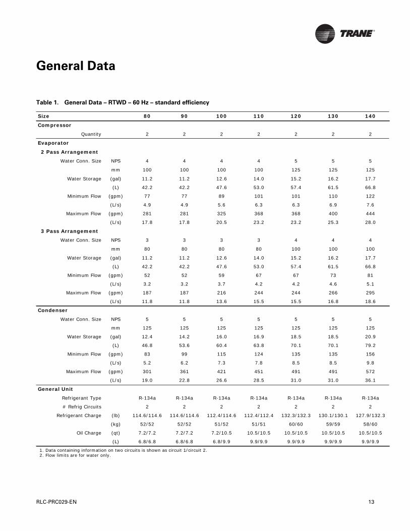
General Data
Table 1. General Data – RTWD – 60 Hz – standard efficiency
Size 80 90 100 110 120 130 140
Compressor
Quantity 2 2 2 2 2 2 2
Evaporator
2 Pass Arrangement
Water Conn. Size NPS 4 4 4 4 5 5 5
mm 100 100 100 100 125 125 125
Water Storage (gal) 11.2 11.2 12.6 14.0 15.2 16.2 17.7
(L) 42.2 42.2 47.6 53.0 57.4 61.5 66.8
Minimum Flow (gpm) 77 77 89 101 101 110 122
(L/s) 4.9 4.9 5.6 6.3 6.3 6.9 7.6
Maximum Flow (gpm) 281 281 325 368 368 400 444
(L/s) 17.8 17.8 20.5 23.2 23.2 25.3 28.0
3 Pass Arrangement
Water Conn. Size NPS 3 3 3 3 4 4 4
mm 80 80 80 80 100 100 100
Water Storage (gal) 11.2 11.2 12.6 14.0 15.2 16.2 17.7
(L) 42.2 42.2 47.6 53.0 57.4 61.5 66.8
Minimum Flow (gpm) 52 52 59 67 67 73 81
(L/s) 3.2 3.2 3.7 4.2 4.2 4.6 5.1
Maximum Flow (gpm) 187 187 216 244 244 266 295
(L/s) 11.8 11.8 13.6 15.5 15.5 16.8 18.6
Condenser
Water Conn. Size NPS 5 5 5 5 5 5 5
mm 125 125 125 125 125 125 125
Water Storage (gal) 12.4 14.2 16.0 16.9 18.5 18.5 20.9
(L) 46.8 53.6 60.4 63.8 70.1 70.1 79.2
Minimum Flow (gpm) 83 99 115 124 135 135 156
(L/s) 5.2 6.2 7.3 7.8 8.5 8.5 9.8
Maximum Flow (gpm) 301 361 421 451 491 491 572
(L/s) 19.0 22.8 26.6 28.5 31.0 31.0 36.1
General Unit
Refrigerant Type R-134a R-134a R-134a R-134a R-134a R-134a R-134a
# Refrig Circuits 2 2 2 2 2 2 2
Refrigerant Charge (lb) 114.6/114.6 114.6/114.6 112.4/114.6 112.4/112.4 132.3/132.3 130.1/130.1 127.9/132
(kg) 52/52 52/52 51/52 51/51 60/60 59/59 58/60
Oil Charge (qt) 7.2/7.2 7.2/7.2 7.2/10.5 10.5/10.5 10.5/10.5 10.5/10.5 10.5/10.5
(L) 6.8/6.8 6.8/6.8 6.8/9.9 9.9/9.9 9.9/9.9 9.9/9.9 9.9/9.9
1. Data containing information on two circuits is shown as circuit 1/circuit 2.2. Flow limits are for water only.
RLC-PRC029-EN 13
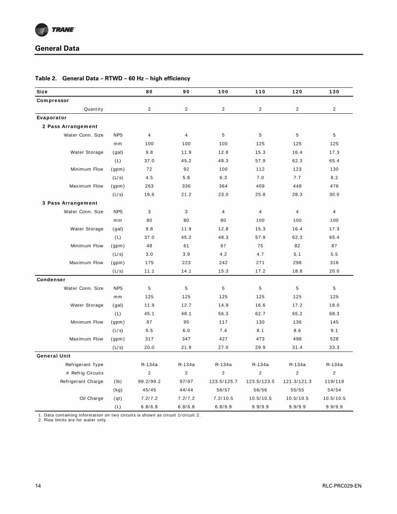
General Data
Table 2. General Data – RTWD – 60 Hz – high efficiency
Size 80 90 100 110 120 130
Compressor
Quantity 2 2 2 2 2 2
Evaporator
2 Pass Arrangement
Water Conn. Size NPS 4 4 5 5 5 5
mm 100 100 100 125 125 125
Water Storage (gal) 9.8 11.9 12.8 15.3 16.4 17.3
(L) 37.0 45.2 48.3 57.9 62.3 65.4
Minimum Flow (gpm) 72 92 100 112 123 130
(L/s) 4.5 5.8 6.3 7.0 7.7 8.2
Maximum Flow (gpm) 263 336 364 409 448 476
(L/s) 16.6 21.2 23.0 25.8 28.3 30.0
3 Pass Arrangement
Water Conn. Size NPS 3 3 4 4 4 4
mm 80 80 80 100 100 100
Water Storage (gal) 9.8 11.9 12.8 15.3 16.4 17.3
(L) 37.0 45.2 48.3 57.9 62.3 65.4
Minimum Flow (gpm) 48 61 67 75 82 87
(L/s) 3.0 3.9 4.2 4.7 5.1 5.5
Maximum Flow (gpm) 175 223 242 271 298 316
(L/s) 11.1 14.1 15.3 17.2 18.8 20.0
Condenser
Water Conn. Size NPS 5 5 5 5 5 5
mm 125 125 125 125 125 125
Water Storage (gal) 11.9 12.7 14.9 16.6 17.2 18.0
(L) 45.1 48.1 56.3 62.7 65.2 68.3
Minimum Flow (gpm) 87 95 117 130 136 145
(L/s) 5.5 6.0 7.4 8.1 8.6 9.1
Maximum Flow (gpm) 317 347 427 473 498 528
(L/s) 20.0 21.9 27.0 29.9 31.4 33.3
General Unit
Refrigerant Type R-134a R-134a R-134a R-134a R-134a R-134a
# Refrig Circuits 2 2 2 2 2 2
Refrigerant Charge (lb) 99.2/99.2 97/97 123.5/125.7 123.5/123.5 121.3/121.3 119/119
(kg) 45/45 44/44 56/57 56/56 55/55 54/54
Oil Charge (qt) 7.2/7.2 7.2/7.2 7.2/10.5 10.5/10.5 10.5/10.5 10.5/10.5
(L) 6.8/6.8 6.8/6.8 6.8/9.9 9.9/9.9 9.9/9.9 9.9/9.9
1. Data containing information on two circuits is shown as circuit 1/circuit 2.2. Flow limits are for water only.
14 RLC-PRC029-EN
General Data
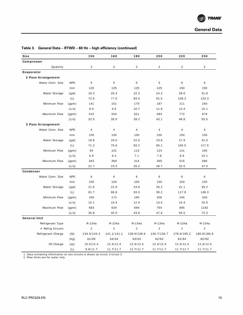
Table 3. General Data – RTWD – 60 Hz – high efficiency (continued)
Size 150 160 180 200 220 250
Compressor
Quantity 2 2 2 2 2 2
Evaporator
2 Pass Arrangement
Water Conn. Size NPS 5 5 5 5 6 6
mm 125 125 125 125 150 150
Water Storage (gal) 19.2 20.3 22.3 24.2 28.6 31.8
(L) 72.6 77.0 84.5 91.5 108.3 120.3
Minimum Flow (gpm) 141 151 170 187 211 240
(L/s) 8.9 9.5 10.7 11.8 13.3 15.1
Maximum Flow (gpm) 515 554 621 683 772 879
(L/s) 32.5 35.0 39.2 43.1 48.8 55.5
3 Pass Arrangement
Water Conn. Size NPS 4 4 4 4 4 4
mm 100 100 100 100 100 100
Water Storage (gal) 18.8 20.0 22.0 23.8 27.9 31.0
(L) 71.2 75.6 83.2 90.1 105.5 117.5
Minimum Flow (gpm) 94 101 113 124 141 160
(L/s) 5.9 6.4 7.1 7.8 8.9 10.1
Maximum Flow (gpm) 343 369 414 455 515 586
(L/s) 21.7 23.3 26.2 28.7 32.5 37.0
Condenser
Water Conn. Size NPS 6 6 6 6 6 6
mm 150 150 150 150 150 150
Water Storage (gal) 21.6 22.9 24.6 26.2 31.1 39.2
(L) 81.7 86.8 93.0 99.2 117.8 148.3
Minimum Flow (gpm) 160 173 190 206 245 326
(L/s) 10.1 10.9 12.0 13.0 15.4 20.5
Maximum Flow (gpm) 583 634 694 754 895 1192
(L/s) 36.8 40.0 43.8 47.6 56.5 75.3
General Unit
Refrigerant Type R-134a R-134a R-134a R-134a R-134a R-134a
# Refrig Circuits 2 2 2 2 2 2
Refrigerant Charge (lb) 134.5/143.3 141.1/141.1 138.9/138.9 136.7/136.7 178.6/185.2 180.8/180.8
(kg) 61/65 64/64 63/63 62/62 81/84 82/82
Oil Charge (qt) 10.5/12.4 12.4/12.4 12.4/12.4 12.4/12.4 12.4/12.4 12.4/12.4
(L) 9.9/11.7 11.7/11.7 11.7/11.7 11.7/11.7 11.7/11.7 11.7/11.7
1. Data containing information on two circuits is shown as circuit 1/circuit 2.2. Flow limits are for water only.
RLC-PRC029-EN 15
General Data
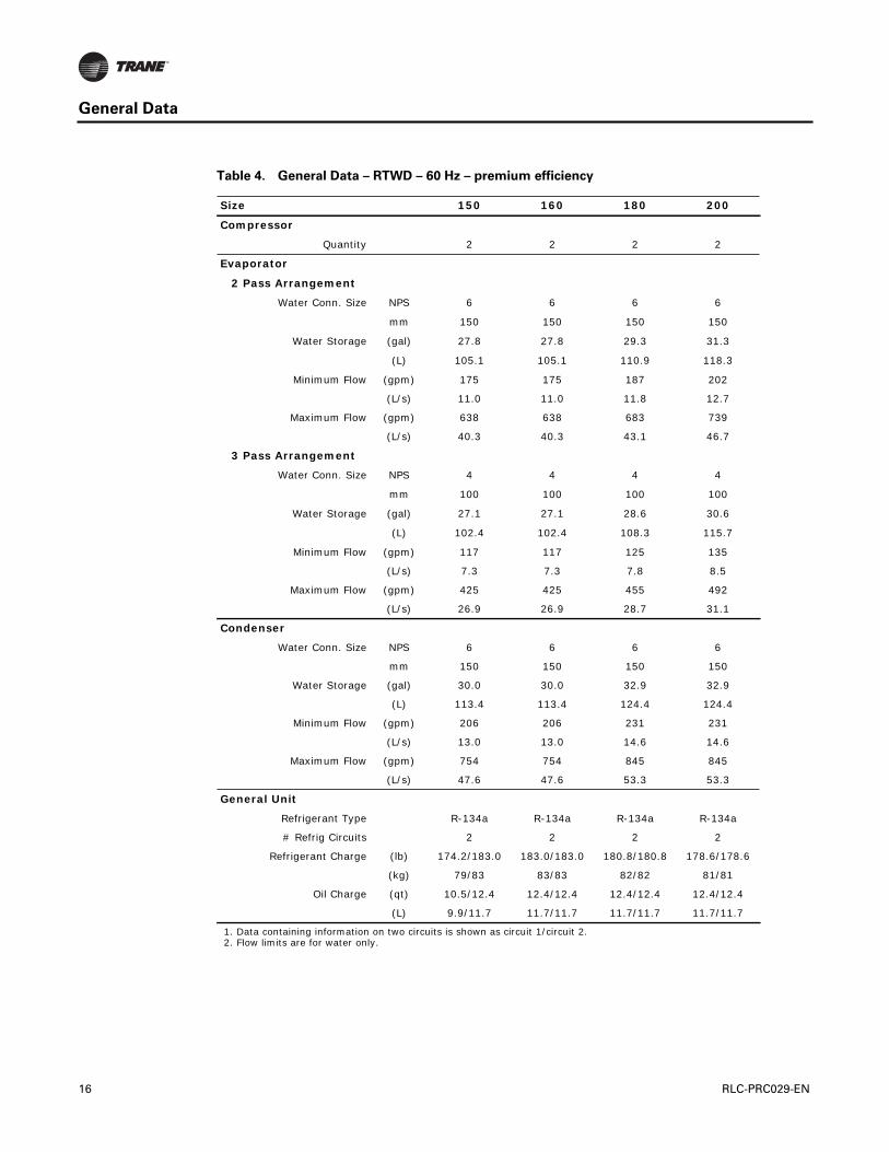
Table 4. General Data – RTWD – 60 Hz – premium efficiency
Size 150 160 180 200
Compressor
Quantity 2 2 2 2
Evaporator
2 Pass Arrangement
Water Conn. Size NPS 6 6 6 6
mm 150 150 150 150
Water Storage (gal) 27.8 27.8 29.3 31.3
(L) 105.1 105.1 110.9 118.3
Minimum Flow (gpm) 175 175 187 202
(L/s) 11.0 11.0 11.8 12.7
Maximum Flow (gpm) 638 638 683 739
(L/s) 40.3 40.3 43.1 46.7
3 Pass Arrangement
Water Conn. Size NPS 4 4 4 4
mm 100 100 100 100
Water Storage (gal) 27.1 27.1 28.6 30.6
(L) 102.4 102.4 108.3 115.7
Minimum Flow (gpm) 117 117 125 135
(L/s) 7.3 7.3 7.8 8.5
Maximum Flow (gpm) 425 425 455 492
(L/s) 26.9 26.9 28.7 31.1
Condenser
Water Conn. Size NPS 6 6 6 6
mm 150 150 150 150
Water Storage (gal) 30.0 30.0 32.9 32.9
(L) 113.4 113.4 124.4 124.4
Minimum Flow (gpm) 206 206 231 231
(L/s) 13.0 13.0 14.6 14.6
Maximum Flow (gpm) 754 754 845 845
(L/s) 47.6 47.6 53.3 53.3
General Unit
Refrigerant Type R-134a R-134a R-134a R-134a
# Refrig Circuits 2 2 2 2
Refrigerant Charge (lb) 174.2/183.0 183.0/183.0 180.8/180.8 178.6/178.6
(kg) 79/83 83/83 82/82 81/81
Oil Charge (qt) 10.5/12.4 12.4/12.4 12.4/12.4 12.4/12.4
(L) 9.9/11.7 11.7/11.7 11.7/11.7 11.7/11.7
1. Data containing information on two circuits is shown as circuit 1/circuit 2.2. Flow limits are for water only.
16 RLC-PRC029-EN

General Data
Table 5. General Data – RTUD – 60 Hz
Size 80 90 100 110 120 130
Compressor
Quantity 2 2 2 2 2 2
Evaporator
2 Pass Arrangement
Water Conn. Size NPS 4 4 4 5 5 5
mm 100 100 100 125 125 125
Water Storage (gal) 9.8 10.6 12.0 14.0 15.3 15.3
(L) 37.1 40.2 45.3 53.0 58.0 58.0
Minimum Flow (gpm) 77 79 91 99 111 111
(L/s) 4.9 5.0 5.7 6.2 7.0 7.0
Maximum Flow (gpm) 281 291 335 363 408 408
(L/s) 17.7 21.2 23.0 25.8 28.3 30.0
3 Pass Arrangement
Water Conn. Size NPS 3 3 3 4 4 4
mm 80 80 80 100 100 100
Water Storage (gal) 9.5 10.3 11.6 13.7 15.1 15.1
(L) 36.0 39.0 44.0 52.0 57.0 57.0
Minimum Flow (gpm) 51 53 61 66 74 74
(L/s) 3.2 3.3 3.8 4.2 4.7 4.7
Maximum Flow (gpm) 187 194 224 242 272 272
(L/s) 11.8 12.2 14.1 15.3 17.2 17.2
General Unit
Refrigerant Type R-134a R-134a R-134a R-134a R-134a R-134a
# Refrig Circuits 2 2 2 2 2 2
Refrigerant Charge (lb) 50/50 49/49 47/47 65/65 64/64 64/64
(kg) 22.7/22.7 22.2/22.2 21.3/21.3 29.5/29.5 29.0/29.0 29.0/29.0
Oil Charge (qt) 7.2/7.2 7.2/7.2 7.2/10.5 10.5/10.5 10.5/10.5 10.5/10.5
(L) 6.8/6.8 6.8/6.8 6.8/9.9 9.9/9.9 9.9/9.9 9.9/9.9
Discharge Connection Diameter
(inch) 2.1 2.1 2.1 2.6 2.6 2.6
Liquid Connection Diameter (inch) 1.1 1.1 1.1 1.4 1.4 1.4
1. Data containing information on two circuits is shown as circuit 1/circuit 2.2. Flow limits are for water only.
RLC-PRC029-EN 17
General Data
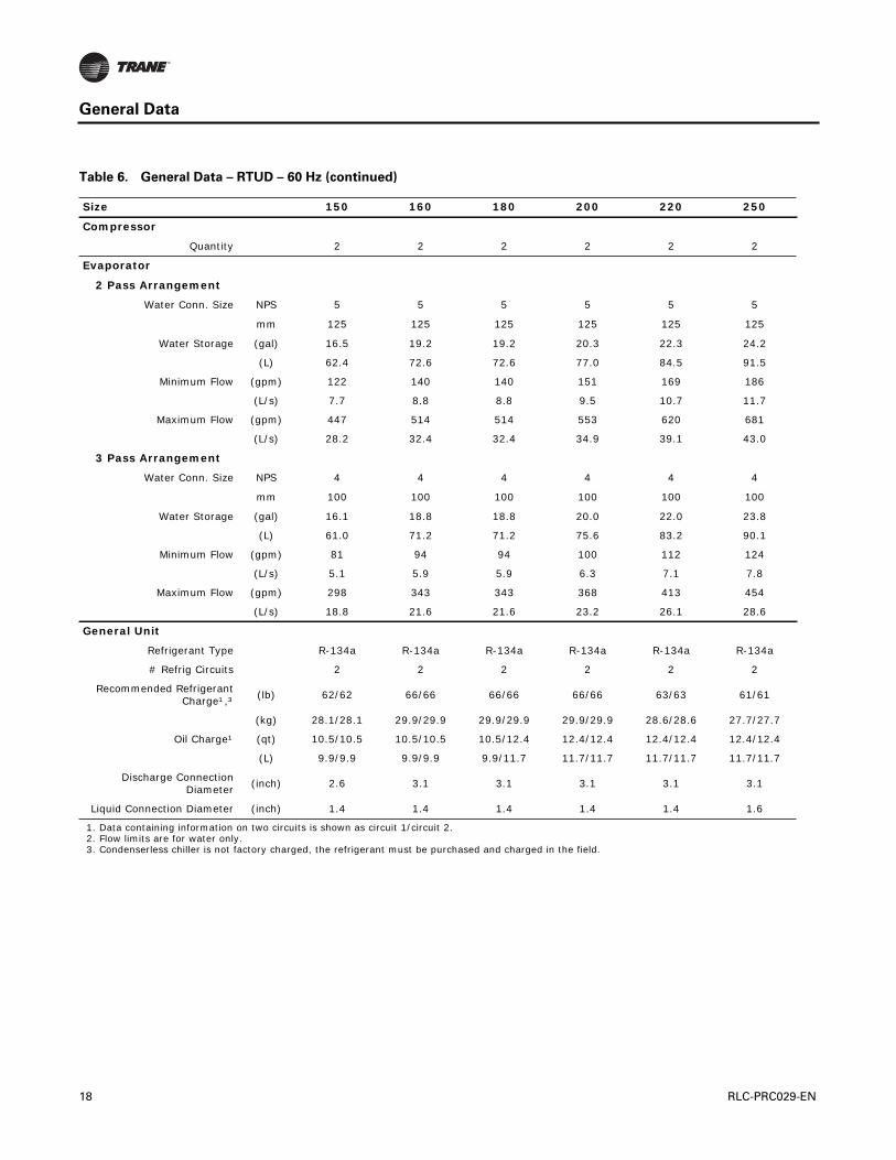
Table 6. General Data – RTUD – 60 Hz (continued)
Size 150 160 180 200 220 250
Compressor
Quantity 2 2 2 2 2 2
Evaporator
2 Pass Arrangement
Water Conn. Size NPS 5 5 5 5 5 5
mm 125 125 125 125 125 125
Water Storage (gal) 16.5 19.2 19.2 20.3 22.3 24.2
(L) 62.4 72.6 72.6 77.0 84.5 91.5
Minimum Flow (gpm) 122 140 140 151 169 186
(L/s) 7.7 8.8 8.8 9.5 10.7 11.7
Maximum Flow (gpm) 447 514 514 553 620 681
(L/s) 28.2 32.4 32.4 34.9 39.1 43.0
3 Pass Arrangement
Water Conn. Size NPS 4 4 4 4 4 4
mm 100 100 100 100 100 100
Water Storage (gal) 16.1 18.8 18.8 20.0 22.0 23.8
(L) 61.0 71.2 71.2 75.6 83.2 90.1
Minimum Flow (gpm) 81 94 94 100 112 124
(L/s) 5.1 5.9 5.9 6.3 7.1 7.8
Maximum Flow (gpm) 298 343 343 368 413 454
(L/s) 18.8 21.6 21.6 23.2 26.1 28.6
General Unit
Refrigerant Type R-134a R-134a R-134a R-134a R-134a R-134a
# Refrig Circuits 2 2 2 2 2 2
Recommended Refrigerant Charge¹,³
(lb) 62/62 66/66 66/66 66/66 63/63 61/61
(kg) 28.1/28.1 29.9/29.9 29.9/29.9 29.9/29.9 28.6/28.6 27.7/27.7
Oil Charge¹ (qt) 10.5/10.5 10.5/10.5 10.5/12.4 12.4/12.4 12.4/12.4 12.4/12.4
(L) 9.9/9.9 9.9/9.9 9.9/11.7 11.7/11.7 11.7/11.7 11.7/11.7
Discharge Connection Diameter
(inch) 2.6 3.1 3.1 3.1 3.1 3.1
Liquid Connection Diameter (inch) 1.4 1.4 1.4 1.4 1.4 1.6
1. Data containing information on two circuits is shown as circuit 1/circuit 2.2. Flow limits are for water only.3. Condenserless chiller is not factory charged, the refrigerant must be purchased and charged in the field.
18 RLC-PRC029-EN
General Data
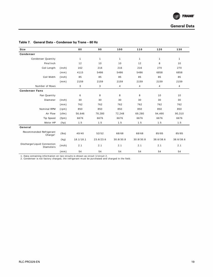
Table 7. General Data – Condenser by Trane – 60 Hz
Size 80 90 100 110 120 130
Condenser
Condenser Quantity 1 1 1 1 1 1
Fins/Inch 12 10 10 12 8 10
Coil Length (inch) 162 216 216 216 270 270
(mm) 4115 5486 5486 5486 6858 6858
Coil Width (inch) 85 85 85 85 85 85
(mm) 2159 2159 2159 2159 2159 2159
Number of Rows 3 3 4 4 4 4
Condenser Fans
Fan Quantity 6 8 8 8 10 10
Diameter (inch) 30 30 30 30 30 30
(mm) 762 762 762 762 762 762
Nominal RPM (rpm) 850 850 850 850 850 850
Air Flow (cfm) 56,646 78,280 72,248 69,280 94,490 90,310
Tip Speed (fpm) 6676 6676 6676 6676 6676 6676
Motor HP (hp) 1.5 1.5 1.5 1.5 1.5 1.5
General
Recommended Refrigerant Charge¹
(lbs) 40/40 52/52 68/68 68/68 85/85 85/85
(kg) 18.1/18.1 23.6/23.6 30.8/30.8 30.8/30.8 38.6/38.6 38.6/38.6
Discharge/Liquid Connection Diameters
(inch) 2.1 2.1 2.1 2.1 2.1 2.1
(mm) 54 54 54 54 54 54
1. Data containing information on two circuits is shown as circuit 1/circuit 2.2. Condenser is not factory charged, the refrigerant must be purchased and charged in the field.
RLC-PRC029-EN 19

General Data
Table 8. General Data – Condenser by Trane – 60 Hz (continued)
Size 150 160 180 200 220 250
Condenser
Condenser Quantity 2 2 2 2 2 2
Fins/Inch¹ 8/12 12/12 12/8 8/8 8/10 10/10
Coil Length¹ (inch) 162/162 162/162 162/216 216/216 216/216 216/216
4115/4115 4115/4115 4115/5486 5486/5486 5486/5486 5486/5486
Coil Width¹ (inch) 85/85 85/85 85/85 85/85 85/85 85/85
2159/2159 2159/2159 2159/2159 2159/2159 2159/2159 2159/2159
Number of Rows 3/3 3/3 3/3 3/3 3/4 4/4
Condenser Fans
Fan Quantity¹ 6/6 6/6 6/8 8/8 8/8 8/8
Diameter (inch) 30 30 30 30 30 30
Nominal RPM (rpm) 850 850 850 850 850 850
Air Flow¹ (cfm)60,954/56,646
56,646/56,646
56,646/81,272
81,272/81,272
81,272/72,248
72,248/72,248
Tip Speed (fpm) 6676 6676 6676 6676 6676 6676
Motor HP (hp) 1.5 1.5 1.5 1.5 1.5 1.5
General
Recommended Refrigerant Charge²,³
(lbs) 76/76 76/76 76/101 101/101 101/134 134/134
(kg) 34.5/34.5 34.5/34.5 34.5/45.8 45.8/45.8 45.8/60.8 60.8/60.8
Discharge/Liquid Connection Diameters
(inch) 2.125 2.125 2.125 2.125 2.125 2.125
(mm) 54 54 54 54 54 54
1. Data containing information on two condensers is shown as cond 1/cond 2.2. Data containing information on two circuits is shown as circuit 1/circuit 2.3. Condenser is not factory charged, the refrigerant must be purchased and charged in the field.
20 RLC-PRC029-EN

Performance Data
Table 9. Performance Data - RTWD - 60 Hz - standard efficiency - I-P units
Evaporator Leaving Water
Temperature (°F)
Condenser Entering Water Temperature (°F)
75 85 95
Unit Size Tons
kW Input EER kW/ton Tons
kW Input EER kW/ton Tons
kW Input EER kW/ton
42
80 78.7 50.3 18.8 0.64 73.8 56.7 15.6 0.768 68.5 64 12.8 0.935
90 89.7 57.3 18.8 0.639 84.6 64.4 15.7 0.762 79 72.8 13 0.921
110 116.3 74.6 18.7 0.641 109.4 84.6 15.5 0.773 102.1 96.3 12.7 0.943
120 127.6 80.5 19 0.631 120 91.1 15.8 0.759 112 103.4 13 0.923
130 135.7 85.9 18.9 0.633 127.7 97.1 15.8 0.761 119.2 110.2 13 0.924
140 148.2 94.4 18.9 0.637 139.5 106.4 15.7 0.763 130.3 120.6 13 0.925
44
80 81.8 50.7 19.4 0.62 76.7 57 16.2 0.742 71.3 64.2 13.3 0.901
90 93.2 57.7 19.4 0.62 87.9 64.8 16.3 0.737 82.2 73 13.5 0.888
100 106.6 66.4 19.3 0.622 100.5 74.8 16.1 0.745 93.9 84.8 13.3 0.903
110 120.8 75.1 19.3 0.621 113.7 84.9 16.1 0.747 106.3 96.5 13.2 0.908
120 132.6 81 19.6 0.611 124.8 91.5 16.4 0.733 116.6 103.8 13.5 0.89
130 141 86.5 19.6 0.614 132.8 97.6 16.3 0.735 124.1 110.6 13.5 0.891
140 154.1 95 19.5 0.617 145.2 107 16.3 0.737 135.7 120.9 13.5 0.891
46
80 85 51.1 20 0.601 79.8 57.3 16.7 0.718 74.2 64.5 13.8 0.869
90 96.7 58.2 19.9 0.602 91.2 65.1 16.8 0.714 85.4 73.2 14 0.857
100 110.7 66.8 19.9 0.604 104.4 75.2 16.6 0.721 97.6 85 13.8 0.871
110 125.3 75.6 19.9 0.603 118.1 85.3 16.6 0.722 110.5 96.8 13.7 0.876
120 137.7 81.7 20.2 0.593 129.8 92 16.9 0.709 121.4 104.2 14 0.858
130 146.4 87.2 20.2 0.595 138.1 98.2 16.9 0.711 129.2 111 14 0.86
140 160.1 95.7 20.1 0.598 150.9 107.6 16.8 0.713 141.2 121.4 14 0.86
48
80 88.2 51.5 20.6 0.584 82.9 57.6 17.3 0.695 77.2 64.8 14.3 0.839
90 100.3 58.7 20.5 0.585 94.7 65.5 17.3 0.692 88.8 73.5 14.5 0.828
100 114.8 67.3 20.5 0.587 108.3 75.6 17.2 0.698 101.5 85.4 14.3 0.841
110 130 76.1 20.5 0.585 122.6 85.8 17.2 0.699 114.8 97.2 14.2 0.846
120 142.9 82.3 20.8 0.576 134.8 92.6 17.5 0.687 126.2 104.6 14.5 0.829
130 152 87.9 20.7 0.578 143.4 98.8 17.4 0.689 134.4 111.6 14.5 0.83
140 166.2 96.5 20.7 0.581 156.8 108.2 17.4 0.69 146.8 121.9 14.5 0.83
50
80 91.5 51.9 21.2 0.567 86.1 58 17.8 0.674 80.3 65.1 14.8 0.81
90 104 59.2 21.1 0.569 98.3 66 17.9 0.671 92.2 73.9 15 0.801
100 119 67.8 21 0.57 112.4 76.1 17.7 0.677 105.4 85.7 14.8 0.813
110 134.7 76.7 21.1 0.569 127.2 86.3 17.7 0.678 119.3 97.6 14.7 0.818
120 148.3 83 21.4 0.56 140 93.2 18 0.666 131.2 105.1 15 0.801
130 157.8 88.7 21.3 0.562 149 99.5 18 0.668 139.6 112.1 14.9 0.803
140 172.5 97.3 21.3 0.564 162.9 108.9 17.9 0.669 152.6 122.4 15 0.802
1. Rated in accordance with AHRI Standard 550/590, based on TOPSS version 144: evaporator temperature drop of 10°F, 3 gpm/ton on the condenser, evaporator fouling factor of 0.0001°F·ft²·h/Btu and condenser fouling factor of 0.00025°F·ft²·h/Btu.
2. Performance is based on 2 pass evaporator configuration.3. Consult Trane representative for additional performance information.4. kW input is for compressors only.5. EER – Energy Efficiency Ratio (Btu/W·h). Power inputs include compressors and control power.6. Interpolation between points is permissible. Extrapolation is not permitted.
RLC-PRC029-EN 21

Performance Data
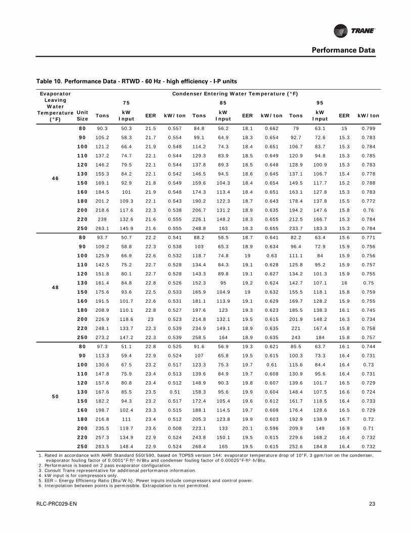
Table 10. Performance Data - RTWD - 60 Hz - high efficiency - I-P units
Evaporator Leaving Water
Temperature (°F)
Condenser Entering Water Temperature (°F)
75 85 95
Unit Size
TonskW
InputEER kW/ton Tons
kW Input
EER kW/ton TonskW
InputEER kW/ton
40
80 80.3 49.2 19.6 0.613 75.3 55.3 16.3 0.735 69.8 62.5 13.4 0.895
90 93.6 56.8 19.8 0.607 88 63.7 16.6 0.724 82 71.8 13.7 0.875
100 107.8 64.9 19.9 0.603 101.2 73.2 16.6 0.723 94.3 82.9 13.7 0.879
110 122.1 73.1 20 0.599 114.7 82.7 16.6 0.721 106.8 94 13.6 0.88
120 130 77.9 20 0.599 122.2 88.1 16.6 0.721 113.9 100.1 13.7 0.879
130 138.1 82.5 20.1 0.598 129.9 93.2 16.7 0.718 121.1 105.9 13.7 0.874
150 150.5 91.2 19.8 0.606 141.6 103 16.5 0.727 132.2 116.9 13.6 0.884
160 164.2 99.2 19.9 0.604 154.6 112 16.6 0.724 144.4 127 13.6 0.879
180 179.1 107.1 20.1 0.598 168.8 120.6 16.8 0.714 157.9 136.5 13.9 0.865
200 194.6 114.9 20.3 0.59 183.6 129.1 17.1 0.703 172 145.9 14.1 0.848
220 213 129.7 19.7 0.609 201 145.9 16.5 0.726 188.4 165 13.7 0.876
250 234.2 142.8 19.7 0.61 220.9 160.6 16.5 0.727 206.9 181.6 13.7 0.878
42
80 83.5 49.5 20.2 0.593 78.4 55.6 16.9 0.709 72.8 62.7 13.9 0.861
90 97.3 57.3 20.4 0.588 91.6 64.1 17.2 0.699 85.5 72 14.2 0.842
100 112.1 65.4 20.6 0.583 105.4 73.5 17.2 0.697 98.3 83.1 14.2 0.845
110 127 73.6 20.7 0.58 119.4 83 17.3 0.695 111.4 94.2 14.2 0.846
120 135.3 78.4 20.7 0.58 127.3 88.4 17.3 0.695 118.7 100.3 14.2 0.845
130 143.7 83 20.8 0.578 135.3 93.6 17.3 0.692 126.3 106.1 14.3 0.84
150 156.6 91.7 20.5 0.586 147.5 103.4 17.1 0.701 137.8 117.1 14.1 0.85
160 170.8 99.8 20.5 0.584 161 112.4 17.2 0.698 150.5 127.2 14.2 0.845
180 186.3 107.8 20.7 0.578 175.8 121.1 17.4 0.689 164.5 136.9 14.4 0.832
200 202.4 115.7 21 0.572 191.1 129.7 17.7 0.679 179.2 146.4 14.7 0.817
220 221.5 130.6 20.3 0.59 209.2 146.6 17.1 0.701 196.3 165.5 14.2 0.843
250 243.6 143.8 20.3 0.59 230 161.3 17.1 0.702 215.6 182.1 14.2 0.845
44
80 86.9 49.9 20.9 0.574 81.6 55.9 17.5 0.685 75.9 62.9 14.5 0.829
90 101.2 57.7 21 0.571 95.3 64.4 17.7 0.676 89.1 72.3 14.8 0.812
100 116.6 65.9 21.2 0.565 109.8 73.9 17.8 0.673 102.5 83.4 14.8 0.813
110 132.1 74.1 21.4 0.561 124.3 83.4 17.9 0.671 116.1 94.5 14.7 0.814
120 140.7 78.9 21.4 0.561 132.5 88.8 17.9 0.671 123.8 100.6 14.8 0.813
130 149.4 83.6 21.5 0.559 140.8 94 18 0.668 131.6 106.4 14.9 0.808
150 162.8 92.3 21.2 0.567 153.5 103.8 17.7 0.677 143.6 117.4 14.7 0.818
160 177.6 100.4 21.2 0.565 167.6 112.9 17.8 0.674 156.7 127.5 14.8 0.813
180 193.7 108.5 21.4 0.56 182.9 121.7 18 0.665 171.4 137.3 15 0.801
200 210.4 116.6 21.6 0.554 198.8 130.4 18.3 0.656 186.6 147 15.2 0.788
220 230.2 131.6 21 0.572 217.6 147.4 17.7 0.677 204.3 166.1 14.8 0.813
250 253.2 144.8 21 0.572 239.2 162.2 17.7 0.678 224.5 182.7 14.8 0.814
22 RLC-PRC029-EN
Performance Data
46
80 90.3 50.3 21.5 0.557 84.8 56.2 18.1 0.662 79 63.1 15 0.799
90 105.2 58.3 21.7 0.554 99.1 64.9 18.3 0.654 92.7 72.6 15.3 0.783
100 121.2 66.4 21.9 0.548 114.2 74.3 18.4 0.651 106.7 83.7 15.3 0.784
110 137.2 74.7 22.1 0.544 129.3 83.9 18.5 0.649 120.9 94.8 15.3 0.785
120 146.2 79.5 22.1 0.544 137.8 89.3 18.5 0.648 128.9 100.9 15.3 0.783
130 155.3 84.2 22.1 0.542 146.5 94.5 18.6 0.645 137.1 106.7 15.4 0.778
150 169.1 92.9 21.8 0.549 159.6 104.3 18.4 0.654 149.5 117.7 15.2 0.788
160 184.5 101 21.9 0.548 174.3 113.4 18.4 0.651 163.1 127.8 15.3 0.783
180 201.2 109.3 22.1 0.543 190.2 122.3 18.7 0.643 178.4 137.8 15.5 0.772
200 218.6 117.6 22.3 0.538 206.7 131.2 18.9 0.635 194.2 147.6 15.8 0.76
220 239 132.6 21.6 0.555 226.1 148.2 18.3 0.655 212.5 166.7 15.3 0.784
250 263.1 145.9 21.6 0.555 248.8 163 18.3 0.655 233.7 183.3 15.3 0.784
48
80 93.7 50.7 22.2 0.541 88.2 56.5 18.7 0.641 82.2 63.4 15.6 0.771
90 109.2 58.8 22.3 0.538 103 65.3 18.9 0.634 96.4 72.9 15.9 0.756
100 125.9 66.9 22.6 0.532 118.7 74.8 19 0.63 111.1 84 15.9 0.756
110 142.5 75.2 22.7 0.528 134.4 84.3 19.1 0.628 125.8 95.2 15.9 0.757
120 151.8 80.1 22.7 0.528 143.3 89.8 19.1 0.627 134.2 101.3 15.9 0.755
130 161.4 84.8 22.8 0.526 152.3 95 19.2 0.624 142.7 107.1 16 0.75
150 175.6 93.6 22.5 0.533 165.9 104.9 19 0.632 155.5 118.1 15.8 0.759
160 191.5 101.7 22.6 0.531 181.1 113.9 19.1 0.629 169.7 128.2 15.9 0.755
180 208.9 110.1 22.8 0.527 197.6 123 19.3 0.623 185.5 138.3 16.1 0.745
200 226.9 118.6 23 0.523 214.8 132.1 19.5 0.615 201.9 148.2 16.3 0.734
220 248.1 133.7 22.3 0.539 234.9 149.1 18.9 0.635 221 167.4 15.8 0.758
250 273.2 147.2 22.3 0.539 258.5 164 18.9 0.635 243 184 15.8 0.757
50
80 97.3 51.1 22.8 0.525 91.6 56.9 19.3 0.621 85.5 63.7 16.1 0.744
90 113.3 59.4 22.9 0.524 107 65.8 19.5 0.615 100.3 73.3 16.4 0.731
100 130.6 67.5 23.2 0.517 123.3 75.3 19.7 0.61 115.6 84.4 16.4 0.73
110 147.8 75.9 23.4 0.513 139.6 84.9 19.7 0.608 130.9 95.6 16.4 0.731
120 157.6 80.8 23.4 0.512 148.9 90.3 19.8 0.607 139.6 101.7 16.5 0.729
130 167.6 85.5 23.5 0.51 158.3 95.6 19.9 0.604 148.4 107.5 16.6 0.724
150 182.2 94.3 23.2 0.517 172.4 105.4 19.6 0.612 161.7 118.5 16.4 0.733
160 198.7 102.4 23.3 0.515 188.1 114.5 19.7 0.609 176.4 128.6 16.5 0.729
180 216.8 111 23.4 0.512 205.3 123.8 19.9 0.603 192.9 138.9 16.7 0.72
200 235.5 119.7 23.6 0.508 223.1 133 20.1 0.596 209.9 149 16.9 0.71
220 257.3 134.9 22.9 0.524 243.8 150.1 19.5 0.615 229.6 168.2 16.4 0.732
250 283.5 148.4 22.9 0.524 268.4 165 19.5 0.615 252.6 184.8 16.4 0.732
1. Rated in accordance with AHRI Standard 550/590, based on TOPSS version 144: evaporator temperature drop of 10°F, 3 gpm/ton on the condenser, evaporator fouling factor of 0.0001°F·ft²·h/Btu and condenser fouling factor of 0.00025°F·ft²·h/Btu.
2. Performance is based on 2 pass evaporator configuration.3. Consult Trane representative for additional performance information.4. kW input is for compressors only.5. EER – Energy Efficiency Ratio (Btu/W·h). Power inputs include compressors and control power.6. Interpolation between points is permissible. Extrapolation is not permitted.
Table 10. Performance Data - RTWD - 60 Hz - high efficiency - I-P units
Evaporator Leaving Water
Temperature (°F)
Condenser Entering Water Temperature (°F)
75 85 95
Unit Size
TonskW
InputEER kW/ton Tons
kW Input
EER kW/ton TonskW
InputEER kW/ton
RLC-PRC029-EN 23
Performance Data
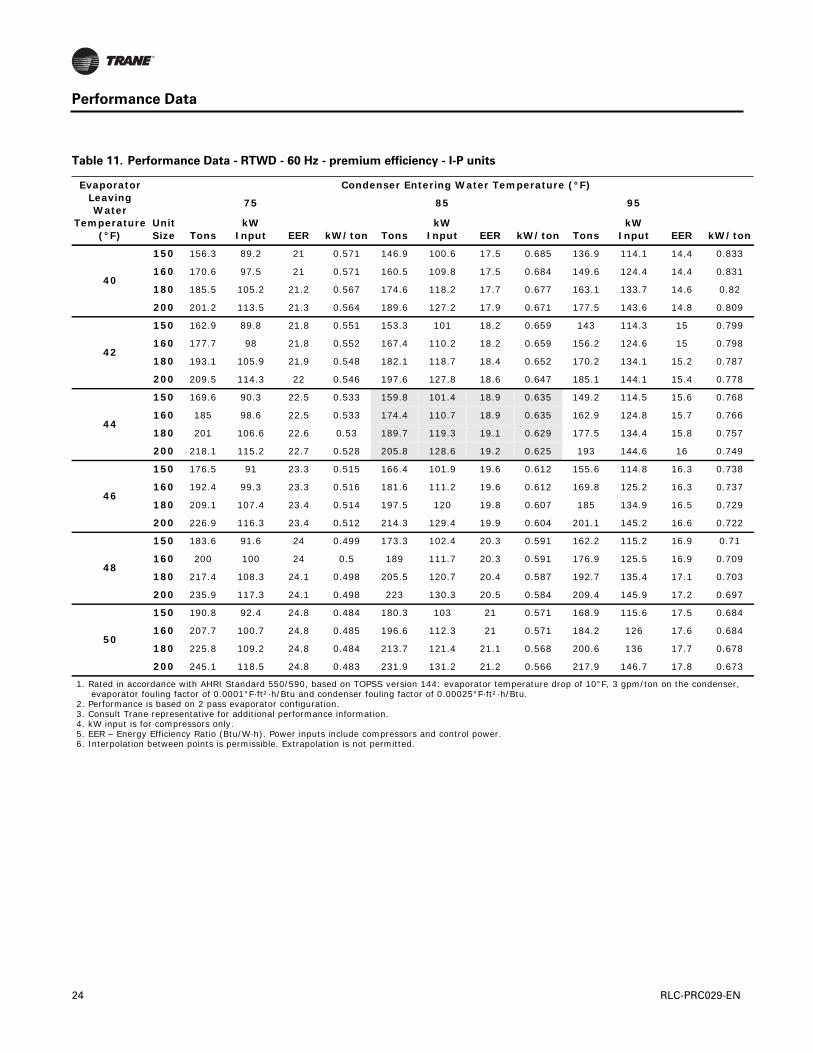
Table 11. Performance Data - RTWD - 60 Hz - premium efficiency - I-P units
Evaporator Leaving Water
Temperature (°F)
Condenser Entering Water Temperature (°F)
75 85 95
Unit Size Tons
kW Input EER kW/ton Tons
kW Input EER kW/ton Tons
kW Input EER kW/ton
40
150 156.3 89.2 21 0.571 146.9 100.6 17.5 0.685 136.9 114.1 14.4 0.833
160 170.6 97.5 21 0.571 160.5 109.8 17.5 0.684 149.6 124.4 14.4 0.831
180 185.5 105.2 21.2 0.567 174.6 118.2 17.7 0.677 163.1 133.7 14.6 0.82
200 201.2 113.5 21.3 0.564 189.6 127.2 17.9 0.671 177.5 143.6 14.8 0.809
42
150 162.9 89.8 21.8 0.551 153.3 101 18.2 0.659 143 114.3 15 0.799
160 177.7 98 21.8 0.552 167.4 110.2 18.2 0.659 156.2 124.6 15 0.798
180 193.1 105.9 21.9 0.548 182.1 118.7 18.4 0.652 170.2 134.1 15.2 0.787
200 209.5 114.3 22 0.546 197.6 127.8 18.6 0.647 185.1 144.1 15.4 0.778
44
150 169.6 90.3 22.5 0.533 159.8 101.4 18.9 0.635 149.2 114.5 15.6 0.768
160 185 98.6 22.5 0.533 174.4 110.7 18.9 0.635 162.9 124.8 15.7 0.766
180 201 106.6 22.6 0.53 189.7 119.3 19.1 0.629 177.5 134.4 15.8 0.757
200 218.1 115.2 22.7 0.528 205.8 128.6 19.2 0.625 193 144.6 16 0.749
46
150 176.5 91 23.3 0.515 166.4 101.9 19.6 0.612 155.6 114.8 16.3 0.738
160 192.4 99.3 23.3 0.516 181.6 111.2 19.6 0.612 169.8 125.2 16.3 0.737
180 209.1 107.4 23.4 0.514 197.5 120 19.8 0.607 185 134.9 16.5 0.729
200 226.9 116.3 23.4 0.512 214.3 129.4 19.9 0.604 201.1 145.2 16.6 0.722
48
150 183.6 91.6 24 0.499 173.3 102.4 20.3 0.591 162.2 115.2 16.9 0.71
160 200 100 24 0.5 189 111.7 20.3 0.591 176.9 125.5 16.9 0.709
180 217.4 108.3 24.1 0.498 205.5 120.7 20.4 0.587 192.7 135.4 17.1 0.703
200 235.9 117.3 24.1 0.498 223 130.3 20.5 0.584 209.4 145.9 17.2 0.697
50
150 190.8 92.4 24.8 0.484 180.3 103 21 0.571 168.9 115.6 17.5 0.684
160 207.7 100.7 24.8 0.485 196.6 112.3 21 0.571 184.2 126 17.6 0.684
180 225.8 109.2 24.8 0.484 213.7 121.4 21.1 0.568 200.6 136 17.7 0.678
200 245.1 118.5 24.8 0.483 231.9 131.2 21.2 0.566 217.9 146.7 17.8 0.673
1. Rated in accordance with AHRI Standard 550/590, based on TOPSS version 144: evaporator temperature drop of 10°F, 3 gpm/ton on the condenser, evaporator fouling factor of 0.0001°F·ft²·h/Btu and condenser fouling factor of 0.00025°F·ft²·h/Btu.
2. Performance is based on 2 pass evaporator configuration.3. Consult Trane representative for additional performance information.4. kW input is for compressors only.5. EER – Energy Efficiency Ratio (Btu/W·h). Power inputs include compressors and control power.6. Interpolation between points is permissible. Extrapolation is not permitted.
24 RLC-PRC029-EN

Performance Data
Table 12. Part Load Performance – RTWD – 60 Hz – I-P units
Standard Efficiency High Efficiency Premium Efficiency
Unit Size
% Load Tons kW kW/ton
IPLV kW/ton Tons kW kW/ton
IPLVkW/ton Tons kW kW/ton
IPLVkW/ton
80
100 76.7 57.0 0.742
0.556
81.6 55.9 0.685
0.51475 57.5 35.2 0.611 61.2 34.5 0.564
50 38.4 19.3 0.502 40.8 18.9 0.465
25 19.2 11.4 0.596 20.4 11.3 0.555
90
100 87.9 64.8 0.737
0.557
95.3 64.4 0.676
0.51075 65.9 39.7 0.603 71.5 39.5 0.552
50 43.9 22.3 0.508 47.7 22.2 0.466
25 22.0 13.2 0.603 23.8 13.0 0.547
100
100 100.5 74.8 0.745
0.554
109.7 73.9 0.673
0.49675 75.3 46.4 0.616 82.3 45.7 0.556
50 50.2 25.6 0.509 54.9 24.8 0.453
25 25.1 13.4 0.533 27.4 13.1 0.479
110
100 113.8 84.9 0.747
0.562
124.3 83.4 0.671
0.50675 85.3 53.1 0.622 93.2 52.1 0.559
50 56.9 28.7 0.504 62.1 28.2 0.454
25 28.4 17.3 0.609 31.1 17.0 0.548
120
100 124.8 91.5 0.733
0.555
132.5 88.8 0.671
0.50775 93.6 57.4 0.613 99.3 55.8 0.562
50 62.4 31.5 0.505 66.2 30.4 0.460
25 31.2 17.6 0.563 33.1 17.2 0.520
130
100 132.8 97.6 0.735
0.563
140.8 94.0 0.668
0.51375 99.6 61.5 0.618 105.6 59.4 0.562
50 66.4 33.6 0.506 70.4 32.4 0.460
25 33.2 20.7 0.623 35.2 20.3 0.568
140
100 145.2 107.0 0.737
0.55675 108.9 68.2 0.627
50 72.6 36.1 0.497
25 36.3 20.7 0.570
150
100 153.5 103.8 0.677
0.517
159.8 101.4 0.635
0.48375 115.1 66.4 0.577 119.8 65.1 0.543
50 76.7 35.9 0.467 79.9 34.4 0.430
25 38.4 20.3 0.528 39.9 20.3 0.509
160
100 167.6 112.9 0.674
0.521
174.4 110.7 0.635
0.49275 125.7 73.0 0.581 130.8 71.5 0.547
50 83.8 38.8 0.463 87.2 37.9 0.434
25 41.9 24.2 0.578 43.6 24.7 0.566
180
100 182.9 121.7 0.666
0.510
189.7 119.3 0.629
0.48275 137.2 78.1 0.570 142.3 76.5 0.538
50 91.4 41.7 0.456 94.8 40.5 0.427
25 45.7 24.7 0.540 47.4 25.2 0.530
RLC-PRC029-EN 25

Performance Data
200
100 198.8 130.4 0.656
0.511
205.8 128.6 0.625
0.48675 149.1 83.2 0.558 154.4 81.9 0.531
50 99.4 45.7 0.460 102.9 44.9 0.437
25 49.7 28.2 0.567 51.5 28.2 0.547
220
100 217.6 147.4 0.677
0.52775 163.2 94.9 0.582
50 108.8 52.5 0.483
25 54.4 28.5 0.523
250
100 239.2 162.2 0.678
0.52875 179.4 105.3 0.587
50 119.6 56.1 0.469
25 59.8 34.9 0.584
1. Rated in accordance with AHRI Standard 550/590, based on TOPSS version 144: evaporator leaving temperature of 44°F and 2.4 gpm/ton, 2 pass evaporator, condenser entering temperature of 85°F and 3 gpm/ton with condenser relief down to 65°F at 50% and 25% loads, evaporator fouling factor of 0.0001°F·ft²·h/Btu and condenser fouling factor of 0.00025°F·ft²·h/Btu.
2. Consult Trane representative for additional performance information.3. kW input is for compressors only. EER – Energy Efficiency Ratio (Btu/W·h). Power inputs include compressors and control power.
Table 12. Part Load Performance – RTWD – 60 Hz – I-P units
Standard Efficiency High Efficiency Premium Efficiency
Unit Size
% Load Tons kW kW/ton
IPLV kW/ton Tons kW kW/ton
IPLVkW/ton Tons kW kW/ton
IPLVkW/ton
26 RLC-PRC029-EN
Performance Data
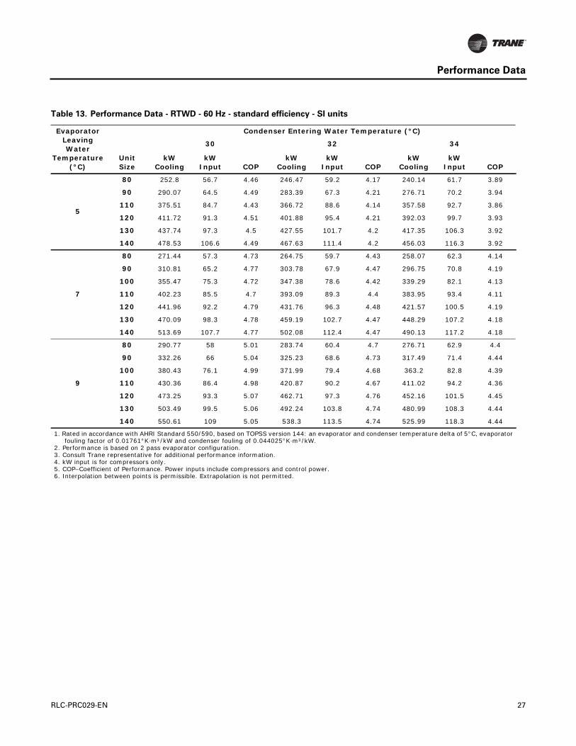
Table 13. Performance Data - RTWD - 60 Hz - standard efficiency - SI units
Evaporator Leaving Water
Temperature (°C)
Condenser Entering Water Temperature (°C)
30 32 34
Unit Size
kW Cooling
kW Input COP
kW Cooling
kWInput COP
kW Cooling
kWInput COP
5
80 252.8 56.7 4.46 246.47 59.2 4.17 240.14 61.7 3.89
90 290.07 64.5 4.49 283.39 67.3 4.21 276.71 70.2 3.94
110 375.51 84.7 4.43 366.72 88.6 4.14 357.58 92.7 3.86
120 411.72 91.3 4.51 401.88 95.4 4.21 392.03 99.7 3.93
130 437.74 97.3 4.5 427.55 101.7 4.2 417.35 106.3 3.92
140 478.53 106.6 4.49 467.63 111.4 4.2 456.03 116.3 3.92
7
80 271.44 57.3 4.73 264.75 59.7 4.43 258.07 62.3 4.14
90 310.81 65.2 4.77 303.78 67.9 4.47 296.75 70.8 4.19
100 355.47 75.3 4.72 347.38 78.6 4.42 339.29 82.1 4.13
110 402.23 85.5 4.7 393.09 89.3 4.4 383.95 93.4 4.11
120 441.96 92.2 4.79 431.76 96.3 4.48 421.57 100.5 4.19
130 470.09 98.3 4.78 459.19 102.7 4.47 448.29 107.2 4.18
140 513.69 107.7 4.77 502.08 112.4 4.47 490.13 117.2 4.18
9
80 290.77 58 5.01 283.74 60.4 4.7 276.71 62.9 4.4
90 332.26 66 5.04 325.23 68.6 4.73 317.49 71.4 4.44
100 380.43 76.1 4.99 371.99 79.4 4.68 363.2 82.8 4.39
110 430.36 86.4 4.98 420.87 90.2 4.67 411.02 94.2 4.36
120 473.25 93.3 5.07 462.71 97.3 4.76 452.16 101.5 4.45
130 503.49 99.5 5.06 492.24 103.8 4.74 480.99 108.3 4.44
140 550.61 109 5.05 538.3 113.5 4.74 525.99 118.3 4.44
1. Rated in accordance with AHRI Standard 550/590, based on TOPSS version 144: an evaporator and condenser temperature delta of 5°C, evaporator fouling factor of 0.01761°K·m³/kW and condenser fouling of 0.044025°K·m³/kW.
2. Performance is based on 2 pass evaporator configuration.3. Consult Trane representative for additional performance information.4. kW input is for compressors only.5. COP–Coefficient of Performance. Power inputs include compressors and control power.6. Interpolation between points is permissible. Extrapolation is not permitted.
RLC-PRC029-EN 27

Performance Data
Table 14. Performance Data - RTWD - 60 Hz - high efficiency - SI units
Evaporator Leaving Water
Temperature (°C)
Condenser Entering Water Temperature (C)
30 32 34
Unit Size
kW Cooling
kWInput COP
kW Cooling
kWInput COP
kW Cooling
kWInput COP
5
80 268.27 55.7 4.81 261.59 58.1 4.5 254.56 60.6 4.2
90 313.63 64.2 4.88 306.24 66.9 4.58 298.86 69.7 4.28
100 361.09 73.7 4.89 352.3 77 4.58 343.86 80.4 4.28
110 408.91 83.4 4.9 399.07 87.1 4.58 389.22 91.1 4.27
120 435.63 88.8 4.9 425.44 92.8 4.58 414.89 97 4.28
130 463.06 94 4.92 452.16 98.2 4.6 441.26 102.6 4.3
150 504.9 103.8 4.86 493.29 108.4 4.55 481.34 113.3 4.25
160 551.31 112.9 4.88 538.65 117.8 4.57 525.64 123 4.27
180 601.94 121.6 4.95 588.23 126.9 4.64 574.51 132.5 4.34
200 654.33 130.2 5.02 639.91 135.8 4.71 625.5 141.7 4.41
220 716.56 147.1 4.87 701.09 153.4 4.57 684.92 160.1 4.28
250 787.58 161.9 4.86 770 168.9 4.56 752.42 176.2 4.27
7
80 287.96 56.3 5.11 281.28 58.7 4.79 273.9 61.1 4.48
90 336.83 65 5.18 329.1 67.6 4.87 321.01 70.3 4.56
100 387.81 74.5 5.2 379.02 77.7 4.88 369.88 81 4.57
110 439.15 84.2 5.22 428.95 87.9 4.88 418.76 91.8 4.56
120 467.98 89.6 5.22 457.43 93.5 4.89 446.53 97.6 4.57
130 497.51 94.8 5.24 486.26 99 4.91 474.66 103.3 4.59
150 542.52 104.7 5.18 530.21 109.2 4.85 517.91 114 4.54
160 592.09 113.8 5.2 578.73 118.7 4.88 565.02 123.8 4.56
180 646.24 122.7 5.26 632.18 127.9 4.94 617.76 133.4 4.63
200 702.5 131.6 5.34 687.38 137.1 5.01 671.91 142.9 4.7
220 768.95 148.6 5.17 752.42 154.8 4.86 735.9 161.4 4.56
250 845.25 163.5 5.17 827.31 170.4 4.85 808.68 177.6 4.55
9
80 309.06 57 5.42 301.67 59.3 5.09 294.29 61.7 4.77
90 361.09 65.8 5.48 353.01 68.4 5.16 344.57 71.1 4.85
100 415.94 75.4 5.52 406.8 78.5 5.18 397.31 81.8 4.86
110 470.79 85.1 5.53 460.24 88.7 5.19 449.7 92.5 4.86
120 502.08 90.5 5.54 490.83 94.4 5.2 479.58 98.5 4.87
130 533.73 95.8 5.57 522.13 99.9 5.22 509.82 104.2 4.89
150 581.55 105.7 5.5 568.89 110.2 5.16 555.53 114.8 4.84
160 634.64 114.8 5.52 620.57 119.6 5.19 606.51 124.7 4.86
180 692.65 124 5.58 677.88 129.2 5.25 662.77 134.6 4.92
200 752.78 133.2 5.65 736.95 138.6 5.31 720.78 144.3 4.99
220 823.1 150.3 5.48 806.22 156.4 5.15 788.64 162.9 4.84
250 905.72 165.3 5.48 886.74 172 5.15 867.4 179.1 4.84
1. Rated in accordance with AHRI Standard 550/590, based on TOPSS version 144: an evaporator and condenser temperature delta of 5°C, evaporator fouling factor of 0.01761°K·m³/kW and condenser fouling of 0.044025°K·m³/kW.
2. Performance is based on 2 pass evaporator configuration.3. Consult Trane representative for additional performance information.4. kW input is for compressors only.5. COP–Coefficient of Performance. Power inputs include compressors and control power.6. Interpolation between points is permissible. Extrapolation is not permitted.
28 RLC-PRC029-EN
Performance Data
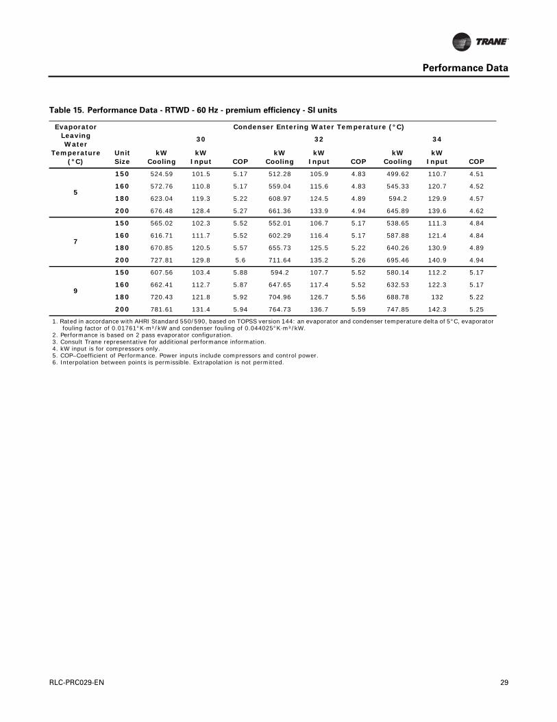
Table 15. Performance Data - RTWD - 60 Hz - premium efficiency - SI units
Evaporator Leaving Water
Temperature (°C)
Condenser Entering Water Temperature (°C)
30 32 34
UnitSize
kW Cooling
kW Input COP
kW Cooling
kW Input COP
kW Cooling
kWInput COP
5
150 524.59 101.5 5.17 512.28 105.9 4.83 499.62 110.7 4.51
160 572.76 110.8 5.17 559.04 115.6 4.83 545.33 120.7 4.52
180 623.04 119.3 5.22 608.97 124.5 4.89 594.2 129.9 4.57
200 676.48 128.4 5.27 661.36 133.9 4.94 645.89 139.6 4.62
7
150 565.02 102.3 5.52 552.01 106.7 5.17 538.65 111.3 4.84
160 616.71 111.7 5.52 602.29 116.4 5.17 587.88 121.4 4.84
180 670.85 120.5 5.57 655.73 125.5 5.22 640.26 130.9 4.89
200 727.81 129.8 5.6 711.64 135.2 5.26 695.46 140.9 4.94
9
150 607.56 103.4 5.88 594.2 107.7 5.52 580.14 112.2 5.17
160 662.41 112.7 5.87 647.65 117.4 5.52 632.53 122.3 5.17
180 720.43 121.8 5.92 704.96 126.7 5.56 688.78 132 5.22
200 781.61 131.4 5.94 764.73 136.7 5.59 747.85 142.3 5.25
1. Rated in accordance with AHRI Standard 550/590, based on TOPSS version 144: an evaporator and condenser temperature delta of 5°C, evaporator fouling factor of 0.01761°K·m³/kW and condenser fouling of 0.044025°K·m³/kW.
2. Performance is based on 2 pass evaporator configuration.3. Consult Trane representative for additional performance information.4. kW input is for compressors only.5. COP–Coefficient of Performance. Power inputs include compressors and control power.6. Interpolation between points is permissible. Extrapolation is not permitted.
RLC-PRC029-EN 29
Performance Data
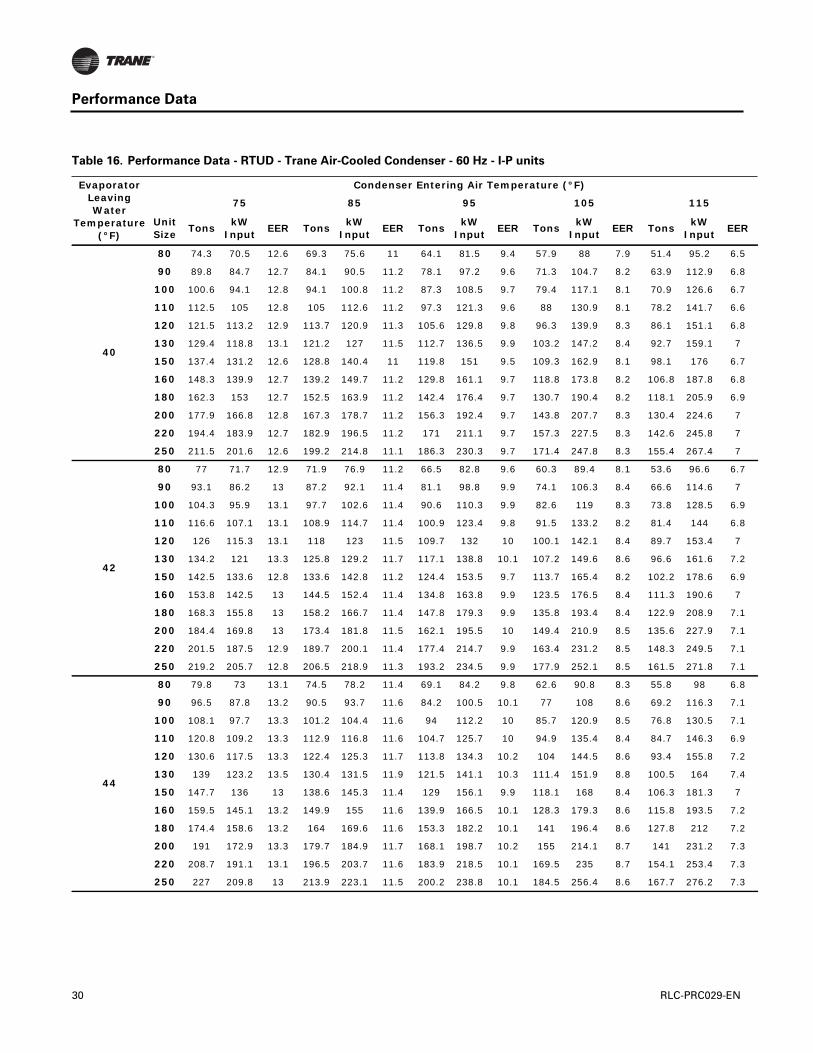
Table 16. Performance Data - RTUD - Trane Air-Cooled Condenser - 60 Hz - I-P units
Evaporator Leaving Water
Temperature (°F)
Condenser Entering Air Temperature (°F)
75 85 95 105 115
Unit Size
TonskW
InputEER Tons
kW Input
EER TonskW
InputEER Tons
kW Input
EER TonskW
InputEER
40
80 74.3 70.5 12.6 69.3 75.6 11 64.1 81.5 9.4 57.9 88 7.9 51.4 95.2 6.5
90 89.8 84.7 12.7 84.1 90.5 11.2 78.1 97.2 9.6 71.3 104.7 8.2 63.9 112.9 6.8
100 100.6 94.1 12.8 94.1 100.8 11.2 87.3 108.5 9.7 79.4 117.1 8.1 70.9 126.6 6.7
110 112.5 105 12.8 105 112.6 11.2 97.3 121.3 9.6 88 130.9 8.1 78.2 141.7 6.6
120 121.5 113.2 12.9 113.7 120.9 11.3 105.6 129.8 9.8 96.3 139.9 8.3 86.1 151.1 6.8
130 129.4 118.8 13.1 121.2 127 11.5 112.7 136.5 9.9 103.2 147.2 8.4 92.7 159.1 7
150 137.4 131.2 12.6 128.8 140.4 11 119.8 151 9.5 109.3 162.9 8.1 98.1 176 6.7
160 148.3 139.9 12.7 139.2 149.7 11.2 129.8 161.1 9.7 118.8 173.8 8.2 106.8 187.8 6.8
180 162.3 153 12.7 152.5 163.9 11.2 142.4 176.4 9.7 130.7 190.4 8.2 118.1 205.9 6.9
200 177.9 166.8 12.8 167.3 178.7 11.2 156.3 192.4 9.7 143.8 207.7 8.3 130.4 224.6 7
220 194.4 183.9 12.7 182.9 196.5 11.2 171 211.1 9.7 157.3 227.5 8.3 142.6 245.8 7
250 211.5 201.6 12.6 199.2 214.8 11.1 186.3 230.3 9.7 171.4 247.8 8.3 155.4 267.4 7
42
80 77 71.7 12.9 71.9 76.9 11.2 66.5 82.8 9.6 60.3 89.4 8.1 53.6 96.6 6.7
90 93.1 86.2 13 87.2 92.1 11.4 81.1 98.8 9.9 74.1 106.3 8.4 66.6 114.6 7
100 104.3 95.9 13.1 97.7 102.6 11.4 90.6 110.3 9.9 82.6 119 8.3 73.8 128.5 6.9
110 116.6 107.1 13.1 108.9 114.7 11.4 100.9 123.4 9.8 91.5 133.2 8.2 81.4 144 6.8
120 126 115.3 13.1 118 123 11.5 109.7 132 10 100.1 142.1 8.4 89.7 153.4 7
130 134.2 121 13.3 125.8 129.2 11.7 117.1 138.8 10.1 107.2 149.6 8.6 96.6 161.6 7.2
150 142.5 133.6 12.8 133.6 142.8 11.2 124.4 153.5 9.7 113.7 165.4 8.2 102.2 178.6 6.9
160 153.8 142.5 13 144.5 152.4 11.4 134.8 163.8 9.9 123.5 176.5 8.4 111.3 190.6 7
180 168.3 155.8 13 158.2 166.7 11.4 147.8 179.3 9.9 135.8 193.4 8.4 122.9 208.9 7.1
200 184.4 169.8 13 173.4 181.8 11.5 162.1 195.5 10 149.4 210.9 8.5 135.6 227.9 7.1
220 201.5 187.5 12.9 189.7 200.1 11.4 177.4 214.7 9.9 163.4 231.2 8.5 148.3 249.5 7.1
250 219.2 205.7 12.8 206.5 218.9 11.3 193.2 234.5 9.9 177.9 252.1 8.5 161.5 271.8 7.1
44
80 79.8 73 13.1 74.5 78.2 11.4 69.1 84.2 9.8 62.6 90.8 8.3 55.8 98 6.8
90 96.5 87.8 13.2 90.5 93.7 11.6 84.2 100.5 10.1 77 108 8.6 69.2 116.3 7.1
100 108.1 97.7 13.3 101.2 104.4 11.6 94 112.2 10 85.7 120.9 8.5 76.8 130.5 7.1
110 120.8 109.2 13.3 112.9 116.8 11.6 104.7 125.7 10 94.9 135.4 8.4 84.7 146.3 6.9
120 130.6 117.5 13.3 122.4 125.3 11.7 113.8 134.3 10.2 104 144.5 8.6 93.4 155.8 7.2
130 139 123.2 13.5 130.4 131.5 11.9 121.5 141.1 10.3 111.4 151.9 8.8 100.5 164 7.4
150 147.7 136 13 138.6 145.3 11.4 129 156.1 9.9 118.1 168 8.4 106.3 181.3 7
160 159.5 145.1 13.2 149.9 155 11.6 139.9 166.5 10.1 128.3 179.3 8.6 115.8 193.5 7.2
180 174.4 158.6 13.2 164 169.6 11.6 153.3 182.2 10.1 141 196.4 8.6 127.8 212 7.2
200 191 172.9 13.3 179.7 184.9 11.7 168.1 198.7 10.2 155 214.1 8.7 141 231.2 7.3
220 208.7 191.1 13.1 196.5 203.7 11.6 183.9 218.5 10.1 169.5 235 8.7 154.1 253.4 7.3
250 227 209.8 13 213.9 223.1 11.5 200.2 238.8 10.1 184.5 256.4 8.6 167.7 276.2 7.3
30 RLC-PRC029-EN

Performance Data
46
80 82.6 74.3 13.3 77.2 79.6 11.6 71.6 85.5 10 65 92.1 8.5 58.1 99.4 7
90 99.9 89.4 13.4 93.7 95.3 11.8 87.3 102.1 10.3 79.9 109.7 8.7 72 118.1 7.3
100 111.9 99.5 13.5 104.9 106.3 11.8 97.4 114.2 10.2 88.9 122.9 8.7 79.8 132.6 7.2
110 125 111.4 13.5 116.9 119 11.8 108.4 127.9 10.2 98.5 137.7 8.6 88 148.6 7.1
120 135.3 119.7 13.6 126.8 127.5 11.9 118 136.6 10.4 107.9 146.8 8.8 97.1 158.2 7.4
130 144 125.5 13.8 135.2 133.8 12.1 125.9 143.4 10.5 115.6 154.4 9 104.5 166.5 7.5
150 153 138.5 13.3 143.6 147.8 11.7 133.8 158.7 10.1 122.5 170.7 8.6 110.5 184 7.2
160 165.2 147.8 13.4 155.4 157.8 11.8 145 169.3 10.3 133.1 182.2 8.8 120.3 196.4 7.4
180 180.5 161.5 13.4 169.9 172.5 11.8 158.8 185.3 10.3 146.3 199.4 8.8 132.8 215.1 7.4
200 197.7 176.1 13.5 186.1 188.1 11.9 174.2 202 10.3 160.7 217.5 8.9 146.4 234.6 7.5
220 216 194.8 13.3 203.5 207.5 11.8 190.5 222.3 10.3 175.7 238.8 8.8 159.9 257.3 7.5
250 234.9 214.1 13.2 221.4 227.4 11.7 207.3 243.1 10.2 191.1 260.8 8.8 174 280.7 7.4
48
80 85.5 75.7 13.6 79.9 80.9 11.9 74.2 86.9 10.2 67.5 93.6 8.7 60.4 100.9 7.2
90 103.4 91 13.6 97.1 97 12 90.4 103.8 10.4 82.9 111.5 8.9 74.8 119.9 7.5
100 115.8 101.4 13.7 108.6 108.3 12 100.9 116.2 10.4 92.2 124.9 8.9 82.9 134.6 7.4
110 129.3 113.6 13.7 121 121.3 12 112.2 130.2 10.3 102 140.1 8.7 91.3 151 7.3
120 140.1 122 13.8 131.3 129.8 12.1 122.2 138.9 10.6 111.9 149.2 9 100.9 160.6 7.5
130 149.1 127.8 14 140 136.1 12.3 130.5 145.8 10.7 119.9 156.8 9.2 108.5 169.1 7.7
150 158.3 141 13.5 148.7 150.4 11.9 138.6 161.3 10.3 127.1 173.4 8.8 114.8 186.8 7.4
160 171.1 150.6 13.6 160.9 160.6 12 150.3 172.2 10.5 138.1 185.1 9 125 199.3 7.5
180 186.8 164.5 13.6 175.9 175.6 12 164.5 188.3 10.5 151.6 202.6 9 137.8 218.3 7.6
200 204.5 179.3 13.7 192.6 191.4 12.1 180.3 205.3 10.5 166.6 220.8 9.1 151.9 238 7.7
220 223.5 198.6 13.5 210.6 211.3 12 197.2 226.1 10.5 182 242.7 9 165.9 261.3 7.6
250 243 218.4 13.4 229.1 231.8 11.9 214.5 247.5 10.4 197.9 265.3 9 180.3 285.2 7.6
1. Rated in accordance with AHRI Standard 550/590, based on TOPSS version 144: evaporator temperature drop of 10°F, evaporator fouling factor of 0.0001°F·ft²·h/Btu, sea level altitude.
2. Performance is based on 2 pass evaporator configuration.3. Consult Trane representative for additional performance information.4. kW input is for compressors and control power.5. EER – Energy Efficiency Ratio (Btu/W·h). Power inputs include compressors and control power.6. Interpolation between points is permissible. Extrapolation is not permitted.
Table 16. Performance Data - RTUD - Trane Air-Cooled Condenser - 60 Hz - I-P units
Evaporator Leaving Water
Temperature (°F)
Condenser Entering Air Temperature (°F)
75 85 95 105 115
Unit Size
TonskW
InputEER Tons
kW Input
EER TonskW
InputEER Tons
kW Input
EER TonskW
InputEER
RLC-PRC029-EN 31
Performance Data
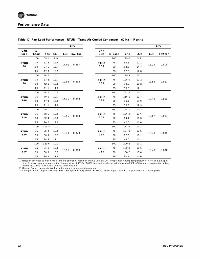
Table 17. Part Load Performance – RTUD – Trane Air-Cooled Condenser – 60 Hz - I-P units
IPLV IPLV
Unit Size
% Load Tons EER EER kw/ton
Unit Size % Load Tons EER EER kw/ton
RTUD 80
100 69.1 9.8
14.01 0.857RTUD 150
100 129.0 9.9
13.25 0.90675 51.8 12.6 75 96.8 12.1
50 34.5 15.7 50 64.6 14.7
25 17.3 12.9 25 32.3 12.0
RTUD 90
100 84.2 10.1
13.98 0.858RTUD 160
100 139.9 10.1
13.53 0.88775 63.2 12.7 75 105.0 12.2
50 42.1 15.8 50 70.0 15.2
25 21.1 11.8 25 35.0 12.1
RTUD 100
100 94.0 10.0
14.15 0.848RTUD 180
100 153.3 10.1
13.48 0.89075 70.5 12.7 75 115.1 12.4
50 47.0 15.9 50 76.7 14.9
25 21.1 11.8 25 38.3 12.3
RTUD 110
100 104.7 10.0
13.95 0.860RTUD 200
100 168.1 10.2
13.57 0.88475 78.5 12.6 75 126.2 12.6
50 52.4 15.8 50 84.1 15.3
25 26.2 12.0 25 42.0 11.0
RTUD 120
100 113.8 10.2
13.79 0.870RTUD 220
100 183.9 10.1
13.48 0.89075 85.4 12.6 75 137.9 12.5
50 56.9 16.7 50 92.0 15.1
25 28.5 11.1 25 46.0 11.1
RTUD 130
100 121.5 10.3
13.91 0.863RTUD 250
100 200.2 10.1
13.46 0.89275 91.1 12.8 75 150.3 12.6
50 60.8 15.7 50 100.2 15.0
25 30.4 11.8 25 50.1 11.0
1. Rated in accordance with AHRI Standard 550/590, based on TOPSS version 144: evaporator leaving temperature of 44°F and 2.4 gpm/ton, 2 pass evaporator, ambient air temperature of 95°F at 100% load and condenser relief down to 55°F at33% loads, evaporator fouling factor of 0.0001°F·ft²·h/Btu and sea level altitude.
2. Consult Trane representative for additional performance information.3. kW input is for compressors only. EER – Energy Efficiency Ratio (Btu/W·h). Power inputs include compressors and control power.
32 RLC-PRC029-EN

Performance Data
Table 18. Performance Data - RTUD - Condenser by Other’s- 60 Hz - I-P units
Evaporator Leaving
Water Temp (F)
Saturated Condenser Temperature (F)
105 125 145
Unit Size Tons kW Input EER Tons kW Input EER Tons kW Input EER
40
80 74.3 61.8 14.4 63.9 73.9 10.4 50.5 89.7 6.8
90 88.8 74 14.4 76.8 88.2 10.5 61.7 106.5 6.9
100 99.8 83.4 14.4 86.2 99.4 10.4 68.7 120.3 6.9
110 112.1 93.2 14.4 96.7 110.9 10.5 76.7 134.4 6.8
120 120 99.4 14.5 103.6 118.2 10.5 82.9 143.1 7
130 127.2 105.3 14.5 110.3 125.4 10.5 89.1 151.8 7
150 137.6 114 14.5 119.7 135.5 10.6 97.3 163.8 7.1
160 148.1 122.8 14.5 129.5 145.7 10.7 105.8 175.9 7.2
180 162.1 132.5 14.7 142.1 157.9 10.8 117.2 191.1 7.4
200 177.9 142.7 15 156.1 170.4 11 129.8 206.7 7.5
220 193.9 160.4 14.5 170.5 189.8 10.8 141.7 228.7 7.4
250 210.6 178.7 14.1 185.4 209.6 10.6 154.1 251.1 7.4
44
80 80.6 63.4 15.3 69.6 75.3 11.1 56 91.1 7.4
90 96.2 76 15.2 83.6 90.1 11.1 68 108.4 7.5
100 108.1 85.7 15.1 93.8 101.5 11.1 75.8 122.5 7.4
110 121.5 95.9 15.2 105.2 113.4 11.1 84.7 136.8 7.4
120 130 102.1 15.3 112.8 120.8 11.2 91.5 145.7 7.5
130 137.8 108 15.3 120 128 11.3 98.2 154.4 7.6
150 149.1 117.1 15.3 130.3 138.3 11.3 107.2 166.6 7.7
160 160.6 126.2 15.3 141 148.8 11.4 116.6 178.9 7.8
180 175.5 136 15.5 154.4 161.1 11.5 128.8 194.2 8
200 192.4 146.4 15.8 169.5 173.9 11.7 142.4 209.9 8.1
220 209.8 165.1 15.2 185.1 194.1 11.4 155.3 232.7 8
250 227.7 184.4 14.8 201.2 214.7 11.2 168.7 256 7.9
48
80 87.2 65 16.1 75.7 76.8 11.8 61.6 92.5 8
90 103.9 78.1 16 90.7 92 11.8 74.6 110.4 8.1
100 116.8 88.1 15.9 101.8 103.8 11.8 83.3 124.7 8
110 131.3 98.7 16 114.2 115.9 11.8 93 139.3 8
120 140.5 105 16.1 122.5 123.4 11.9 100.5 148.2 8.1
130 148.8 110.9 16.1 130.2 130.6 12 107.8 157 8.2
150 161.2 120.3 16.1 141.5 141.3 12 117.6 169.4 8.3
160 173.6 129.7 16.1 153 152.1 12.1 127.8 181.9 8.4
180 189.6 139.8 16.3 167.4 164.5 12.2 140.9 197.4 8.6
200 207.7 150.4 16.6 183.6 177.4 12.4 155.6 213.3 8.8
220 226.4 170.1 16 200.4 198.6 12.1 169.5 236.9 8.6
250 245.6 190.4 15.5 217.7 220.2 11.9 184 261.1 8.5
1. Rated in accordance with AHRI Standard 550/590, based on TOPSS version 144: evaporator temperature drop of 10°F, 20°F sub-cooling, evaporator fouling factor of 0.0001°F·ft²·h/Btu, sea level altitude.
2. Based on 2 pass evaporator configuration.3. Consult Trane representative for additional performance information.4. kW input is for compressors and control power.5. EER – Energy Efficiency Ratio (Btu/W·h). Power inputs include compressors and control power.6. Interpolation between points is permissible. Extrapolation is not permitted.
RLC-PRC029-EN 33

Performance Data
Table 19. Performance Data - RTUD - Condenser by Other’s - 60 Hz - SI units
Evaporator Leaving Water
Temperature (°C)
Saturated Condenser Temperature (°C)
40 50 60
Unit SizekW
CoolingkW
InputCOP
kW Cooling
kWInput
COPkW
CoolingkW
InputCOP
5
80 265.46 61.7 4.3 232.41 72.2 3.22 191.97 85.7 2.24
90 316.79 73.9 4.29 278.82 86.2 3.23 233.11 102 2.28
100 356.17 83.3 4.28 313.28 97.2 3.22 260.18 115.1 2.26
110 400.12 93.1 4.3 351.25 108.5 3.24 290.77 128.6 2.26
120 428.25 99.2 4.32 376.56 115.6 3.26 313.63 136.9 2.29
130 453.92 105.1 4.32 400.47 122.6 3.26 336.13 145.2 2.31
150 491.19 113.8 4.31 434.58 132.5 3.28 366.37 156.8 2.34
160 528.45 122.6 4.31 469.39 142.6 3.29 397.66 168.4 2.36
180 578.38 132.3 4.37 514.74 154.4 3.33 439.15 182.8 2.4
200 634.29 142.4 4.45 565.02 166.5 3.39 484.86 197.6 2.45
220 691.6 160.3 4.31 617.06 185.8 3.32 529.16 219 2.42
250 750.67 178.7 4.2 670.85 205.5 3.26 575.22 240.9 2.39
7
80 285.5 63.1 4.52 250.69 73.5 3.41 209.2 87 2.4
90 340.35 75.7 4.5 300.62 87.9 3.42 253.15 103.7 2.44
100 382.54 85.4 4.48 337.54 99.2 3.4 283.04 117.1 2.42
110 430.01 95.5 4.5 378.67 110.7 3.42 316.44 130.8 2.42
120 460.24 101.7 4.52 406.1 117.9 3.44 341.4 139.2 2.45
130 487.32 107.6 4.53 431.41 124.9 3.45 365.31 147.5 2.47
150 527.75 116.6 4.52 468.68 135.1 3.47 398.36 159.3 2.5
160 568.19 125.7 4.52 506.3 145.4 3.48 432.12 171.1 2.53
180 620.93 135.5 4.58 554.12 157.3 3.52 476.42 185.7 2.57
200 680.35 145.8 4.67 608.27 169.7 3.58 525.29 200.6 2.62
220 741.88 164.6 4.51 663.82 189.7 3.5 573.11 222.8 2.57
250 804.81 183.9 4.38 721.48 210.2 3.43 622.33 245.4 2.54
9
80 305.89 64.6 4.74 270.03 74.9 3.6 227.49 88.3 2.57
90 364.61 77.5 4.7 323.47 89.7 3.6 274.6 105.4 2.6
100 409.97 87.6 4.68 363.2 101.2 3.59 306.95 119 2.58
110 460.95 98.1 4.7 407.5 113.1 3.6 343.51 133 2.58
120 493.29 104.3 4.73 437.04 120.3 3.63 370.23 141.5 2.62
130 522.13 110.2 4.74 463.76 127.3 3.64 395.9 149.9 2.64
150 566.08 119.6 4.73 504.19 137.8 3.66 431.76 161.8 2.67
160 609.32 128.9 4.72 544.63 148.3 3.67 468.33 173.9 2.69
180 665.23 138.9 4.79 595.61 160.4 3.71 515.09 188.6 2.73
200 728.87 149.4 4.88 652.92 172.9 3.77 567.48 203.6 2.79
220 794.26 169.1 4.69 712.69 193.8 3.67 618.46 226.6 2.73
250 861.42 189.4 4.55 773.87 215.2 3.6 671.56 250 2.69
1. Based on TOPSS version 144: evaporator temperature drop of 5°C, 10°C sub-cooling, evaporator fouling factor of 0.01761°K·m³/kW and sea level altitude.2. Performance is based on 2 pass evaporator configuration.3. Consult Trane representative for additional performance information.4. kW input is for compressors and control power.5. COP–Coefficient of Performance. Power inputs include compressors and control power.6. Interpolation between points is permissible. Extrapolation is not permitted.
34 RLC-PRC029-EN

Controls
LCD Touch-Screen Display with Multi-Language Support
The standard DynaView display provided with the Trane CH530 control panel features an LCDtouch-screen, allowing access to all operational inputs and outputs. This display supports manylanguages including: English, Chinese, Dutch, French, German, Italian, Japanese, Korean,Portuguese, Spanish, and Thai.
Display Features Include:
• LCD touch-screen with LED backlighting, for scrolling access to input and output operatinginformation
• Single-screen, folder/tab-style display of all available information on individual components(evaporator, condenser, compressor, etc.)
• Manual override indication
• Password entry/lockout system to enable or disable display
• Automatic and immediate stop capabilities for standard or immediate manual shutdown
• Fast, easy access to available chiller data in tabbed format, including:
• Modes of operation, including normal cooling, ice making and hot water control
• Water temperatures and setpoints, outdoor air temperature
• Loading and limiting status and setpoints
• Average line current
• Start/stop differential timers
• Auto/Manual mode for EXV, slide valve, and head pressure control
• Pump status and override
• Chilled water reset settings
• Optional external setpoints, including:
i. Chilled water, current-limit, condenser leaving hot water temperature setpoint
ii. Ice building
• Reports, listed on a single tabbed screen for easy access, including:
• ASHRAE, containing all guideline 3 report information
• Evaporator, condenser, compressor
• Evaporator, condenser, and compressor reports containing all operational information onindividual components, including:
• Water temperatures
• Refrigerant pressures, temperatures, and approach
• Oil pressure, head pressure control command
• Flow switch status, EXV position
• Compressor starts and run-time
• Line phase percent RLA, amps, and volts
• Alarm and diagnostic information, including:
• Flashing alarms with touch-screen button of alarm condition
• Scrollable list of last ten active diagnostics
• Specific information on applicable diagnostic from list of over one-hundred
• Automatic or manual resetting diagnostic types
RLC-PRC029-EN 35

Controls
LonTalk/Tracer Summit Interface
LonTalk (LCI-C) or Tracer Summit communications capabilities are available, with communicationlink via single twisted-pair wiring to factory-installed, tested communication board.
Required features:
• LonTalk/Tracer Summit Interface
Additional options that may be used:
• Ice making, chilled water temperature reset - outdoor air
External devices required:
• Trane Tracer system or LonTalk compatible system level interface.
Easy Operation and Maintenance
• Remote monitoring and control
• Displays both current operation conditions and scheduled automated control actions
• Concise reports assist in planning for preventative maintenance and verifying performance
• Alarm notification and diagnostic messages aid in quick and accurate troubleshooting
When integrated with a Tracer Summit building management system the total building operationcan be optimized. With this system option, the full breadth of Trane’s HVAC and controls experienceare applied to offer solutions to many facility issues.
LonTalk Chiller Controls
LonTalk is a communications protocol developed by the Echelon™ Corporation. The LonMark™association develops control profiles using the LonTalk communication protocol. LonTalk is a unitlevel communications protocol.
LonTalk Communications Interface for Chillers (LCI-C) provides a generic automation system withthe LonMark chiller profile inputs/outputs. In addition to the standard points, Trane provides othercommonly used network output variables for greater interoperability with any automation system.The complete reference list of Trane LonTalk points is available on the LonMark web site.
Trane controls or another vendor’s system can use the predefined list of points with ease to givethe operator a complete picture of how the system is running.
Tracer Summit
Trane’s depth of experience in chillers and controls makes us a well-qualified choice for automationof chiller plants using water-cooled Series R chillers. The chiller plant control capabilities of theTrane Tracer Summit™ building automation system are unequaled in the industry. Our chiller plantautomation software is fully pre-engineered and tested.
Energy Efficiency
• Sequences starting of chillers to optimize the overall chiller plant energy efficiency
• Individual chillers operate as base, peak, or swing based on capacity and efficiency
• Automatically rotates individual chiller operation to equalize runtime and wear betweenchillers.
• Evaluates and selects the lowest energy consumption alternative from an overall systemperspective.
Regulatory Compliance Documentation
• Gathers information and generates the reports mandated in ASHRAE Guideline 3.
36 RLC-PRC029-EN
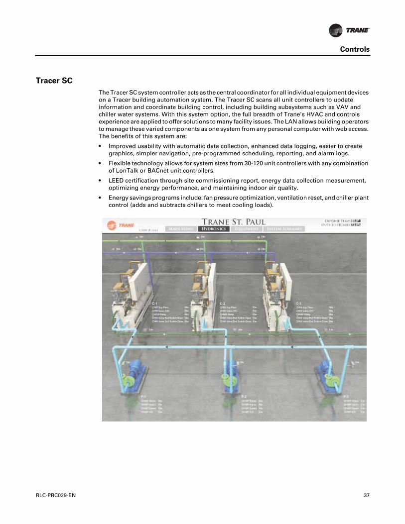
Controls
Tracer SC
The Tracer SC system controller acts as the central coordinator for all individual equipment deviceson a Tracer building automation system. The Tracer SC scans all unit controllers to updateinformation and coordinate building control, including building subsystems such as VAV andchiller water systems. With this system option, the full breadth of Trane’s HVAC and controlsexperience are applied to offer solutions to many facility issues. The LAN allows building operatorsto manage these varied components as one system from any personal computer with web access.The benefits of this system are:
• Improved usability with automatic data collection, enhanced data logging, easier to creategraphics, simpler navigation, pre-programmed scheduling, reporting, and alarm logs.
• Flexible technology allows for system sizes from 30-120 unit controllers with any combinationof LonTalk or BACnet unit controllers.
• LEED certification through site commissioning report, energy data collection measurement,optimizing energy performance, and maintaining indoor air quality.
• Energy savings programs include: fan pressure optimization, ventilation reset, and chiller plantcontrol (adds and subtracts chillers to meet cooling loads).
RLC-PRC029-EN 37

Controls
BACnet Communication Interface
BACnet communications capabilities are available, with communication link via single twisted-pairwiring.
Required features:
• BACnet Interface
Additional options that may be used:
• Ice making, chilled water temperature reset - outdoor air
External devices required:
• BACnet MS/TP network.
BACnet Chiller Controls
BACnet is an open standard communications protocol used by building automation systems.BACnet MS/TP uses RS-485 hardware. This device is a non-programmable communication modulethat connections directly to the CH530 chiller control.
Time of Day Scheduling
Time of day scheduling allows the customer to perform simple chiller scheduling without the needfor a building automation system.
This feature allows the user to set 10 events in a 7 day time period. For each event the user canspecify an activation time and the days of the week the event is active. Any setpoints available canbe specified for each event, such as the leaving chilled water temperature (standard) and thecurrent-limit setpoint (optional if ordered).
Required features:
• Time of day scheduling
Additional options that if ordered may be incorporated into the scheduling:
• External chilled water setpoint
• External current-limit setpoint
• Condenser leaving hot water temperature setpoint
• Ice making initiation
Hardwire Points
Remote devices wired from the control panel are another reliable method of providing auxiliarycontrol to a building automation system. Inputs and outputs can be communicated via a typical 4–20 mA electrical signal, an equivalent 2–10 Vdc signal, or by utilizing contact closures.
Selectable options:
• External chilled water setpoint/External current-limit setpoint
• Ice making control
• Condenser leaving hot water temperature control
• Chilled water temperature reset
• Condenser pressure output
• Motor current analog output
• Programmable relaysavailableoutputsare:alarm-latching,alarm-autoreset,generalalarm,warning, chiller limit mode, compressor running, head pressure relief request, and Tracercontrol
38 RLC-PRC029-EN

Electrical Data
Table 20. Electrical Data - RTWD - 60 Hz - standard efficiency - standard condensing temperature
Unit Size
Rated Voltage
Unit Wiring
Single Point Power - 1 Power Connection
Dual Point Power -2 Power Connections Motor Data
MCA MOP MCA MOP RLA LRA YD LRA XL
80
200/60/3 216 300 122/118 200/200 94/94 276/276 912/912
230/60/3 188 250 106/103 175/175 82/82 238/238 786/786
380/60/3 115 150 65/63 110/110 50/50 138/138 456/456
460/60/3 94 125 53/51 90/90 41/41 114/114 376/376
575/60/3 76 100 43/41 70/70 33/33 93/93 308/308
90
200/60/3 249 350 140/136 225/225 109/109 304/304 1003/1003
230/60/3 217 300 122/119 200/200 95/95 262/262 866/866
380/60/3 130 175 73/71 125/125 57/57 161/161 530/530
460/60/3 110 150 62/60 100/100 48/48 131/131 433/433
575/60/3 87 110 49/48 80/80 38/38 105/105 346/346
100
200/60/3 291 400 140/178 225/300 109/142 304/355 1003/1137
230/60/3 252 350 122/154 200/250 95/123 262/294 866/942
380/60/3 153 225 73/94 125/150 57/75 161/177 530/566
460/60/3 127 175 62/78 100/125 48/62 131/147 433/471
575/60/3 102 150 49/63 80/110 38/50 105/118 346/377
110
200/60/3 324 450 182/178 300/300 142/142 355/355 1137/1137
230/60/3 280 400 157/154 250/250 123/123 294/294 942/942
380/60/3 171 225 96/94 150/150 75/75 177/177 566/566
460/60/3 141 200 80/78 125/125 62/62 147/147 471/471
575/60/3 114 150 64/63 110/110 50/50 118/118 377/377
120
200/60/3 356 500 182/210 300/350 142/168 355/419 1137/1368
230/60/3 309 450 157/183 250/300 123/146 294/367 942/1200
380/60/3 187 250 96/110 150/175 75/88 177/229 566/747
460/60/3 155 225 79/91 125/150 62/73 147/184 471/600
575/60/3 125 175 64/74 110/125 50/59 118/148 377/483
130
200/60/3 382 500 214/210 350/350 168/168 419/419 1368/1368
230/60/3 332 450 186/183 300/300 146/146 367/367 1200/1200
380/60/3 200 250 112/110 200/175 88/88 229/229 747/747
460/60/3 166 225 93/91 150/150 73/73 184/184 600/600
575/60/3 134 175 75/74 125/125 59/59 148/148 483/483
140
200/60/3 425 600 214/253 350/450 168/202 419/487 1368/1498
230/60/3 368 500 186/219 300/350 146/175 367/427 1200/1314
380/60/3 223 300 112/133 200/225 88/106 229/260 747/801
460/60/3 185 250 93/110 150/175 73/88 184/212 600/652
575/60/3 148 200 75/88 125/150 59/70 148/172 483/528
Notes:
1. Voltage Utilization Range: +/- 10% of rated voltage Rated voltage (use range): 208/60/3 (187.2-228.8), 230/60/3(208-254), 380/60/3 (342-418), 460/60/3 (414-506), 575/60/3 (516-633)
2. MCA–minimum circuit ampacity 3. MOP–maximum overcurrent protection 4. RLA–rated load amps are rated in accordance with UL Standard 1995. 5. LRA–locked rotor amps are based on full winding starts. 6. LRA YD–Locked Rotor Amps in Wye configuration. LRA XL–Locked Rotor Amps in the Delta configuration. 7. Local codes may take precedence. 8. Data containing information on two circuits shown as follows: circuit 1/circuit 2. 9. Standard condensing temperature option refers to entering condenser water temperatures 95°F (35°C) and below.
RLC-PRC029-EN 39

Electrical Data
Table 21. Electrical Data - RTWD - 60 Hz - high efficiency - standard condensing temperature
Unit Size
Rated Voltage
Unit Wiring
Single Point Power - 1 Power Connection
Dual Point Power -2 Power Connections Motor Data
MCA MOP MCA MOP RLA LRA YD LRA XL
80
200/60/3 211 300 119/115 200/200 92/92 276/276 912/912
230/60/3 184 250 104/100 175/175 80/80 238/238 786/786
380/60/3 112 150 63/61 110/110 49/49 138/138 456/456
460/60/3 92 125 52/50 90/90 40/40 114/114 376/376
575/60/3 73 100 32/32 93/93 32/32 93/93 308/308
90
200/60/3 245 350 138/134 225/225 107/107 304/304 1003/1003
230/60/3 213 300 120/116 200/200 93/93 262/262 866/866
380/60/3 128 175 72/70 125/125 56/56 161/161 530/530
460/60/3 108 150 61/59 100/100 47/47 131/131 433/433
575/60/3 85 110 48/46 80/80 37/37 105/105 346/346
100
200/60/3 284 400 138/173 225/300 107/138 304/355 1003/1137
230/60/3 247 350 120/150 200/250 93/120 262/294 866/942
380/60/3 149 200 72/91 125/150 56/73 161/177 530/566
460/60/3 124 175 61/75 100/125 47/60 131/147 433/471
575/60/3 98 125 48/60 80/100 37/48 105/118 346/377
110
200/60/3 315 450 177/173 300/300 138/138 355/355 1137/1137
230/60/3 274 350 154/150 250/250 120/120 294/294 942/942
380/60/3 166 225 93/91 150/150 73/73 177/177 566/566
460/60/3 137 175 77/75 125/125 60/60 147/147 471/471
575/60/3 109 150 61/60 100/100 48/48 118/118 377/377
120
200/60/3 347 500 177/205 300/350 138/164 355/419 1137/1368
230/60/3 302 400 154/179 250/300 120/143 294/367 942/1200
380/60/3 184 250 93/109 150/175 73/87 177/229 566/747
460/60/3 152 200 77/90 125/150 60/72 147/184 471/600
575/60/3 121 175 61/71 100/125 48/57 118/148 377/483
130
200/60/3 373 500 209/205 350/350 164/164 419/419 1368/1368
230/60/3 325 450 182/179 300/300 143/143 367/367 1200/1200
380/60/3 198 250 111/109 175/175 87/87 229/229 747/747
460/60/3 164 225 92/90 150/150 72/72 184/184 600/600
575/60/3 130 175 73/71 125/125 57/57 148/148 483/483
150
200/60/3 414 600 210/245 350/400 164/196 419/487 1368/1498
230/60/3 361 500 183/214 300/350 143/171 367/427 1200/1314
380/60/3 218 300 111/129 175/225 87/103 229/260 747/801
460/60/3 182 250 92/108 150/175 72/86 184/212 600/652
575/60/3 145 200 73/87 125/150 57/69 148/172 483/528
160
200/60/3 446 600 250/245 400/400 196/196 487/487 1498/1498
230/60/3 389 500 218/214 350/350 171/171 427/427 1314/1314
380/60/3 234 300 131/129 225/225 103/103 260/260 801/801
460/60/3 196 250 110/108 175/175 86/86 212/212 652/652
575/60/3 157 225 88/87 150/150 69/69 172/172 528/528
180
200/60/3 484 700 250/284 400/500 196/227 487/600 1498/1845
230/60/3 421 600 218/247 350/400 171/197 427/506 1314/1556
380/60/3 256 350 131/150 225/250 103/120 260/316 801/973
460/60/3 213 300 110/125 175/225 86/100 212/252 652/774
575/60/3 171 250 88/100 150/175 69/80 172/205 528/631
40 RLC-PRC029-EN
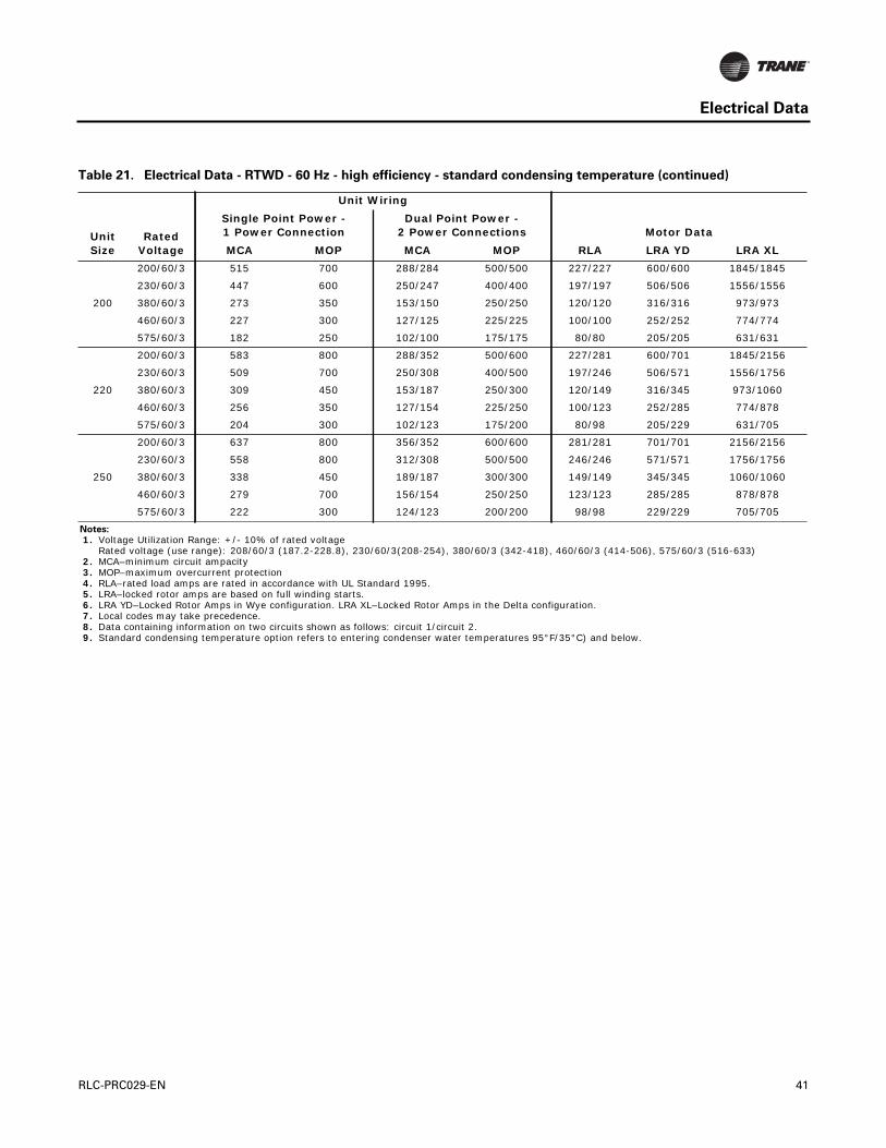
Electrical Data
200
200/60/3 515 700 288/284 500/500 227/227 600/600 1845/1845
230/60/3 447 600 250/247 400/400 197/197 506/506 1556/1556
380/60/3 273 350 153/150 250/250 120/120 316/316 973/973
460/60/3 227 300 127/125 225/225 100/100 252/252 774/774
575/60/3 182 250 102/100 175/175 80/80 205/205 631/631
220
200/60/3 583 800 288/352 500/600 227/281 600/701 1845/2156
230/60/3 509 700 250/308 400/500 197/246 506/571 1556/1756
380/60/3 309 450 153/187 250/300 120/149 316/345 973/1060
460/60/3 256 350 127/154 225/250 100/123 252/285 774/878
575/60/3 204 300 102/123 175/200 80/98 205/229 631/705
250
200/60/3 637 800 356/352 600/600 281/281 701/701 2156/2156
230/60/3 558 800 312/308 500/500 246/246 571/571 1756/1756
380/60/3 338 450 189/187 300/300 149/149 345/345 1060/1060
460/60/3 279 700 156/154 250/250 123/123 285/285 878/878
575/60/3 222 300 124/123 200/200 98/98 229/229 705/705
Notes:
1. Voltage Utilization Range: +/- 10% of rated voltage Rated voltage (use range): 208/60/3 (187.2-228.8), 230/60/3(208-254), 380/60/3 (342-418), 460/60/3 (414-506), 575/60/3 (516-633)
2. MCA–minimum circuit ampacity 3. MOP–maximum overcurrent protection 4. RLA–rated load amps are rated in accordance with UL Standard 1995. 5. LRA–locked rotor amps are based on full winding starts. 6. LRA YD–Locked Rotor Amps in Wye configuration. LRA XL–Locked Rotor Amps in the Delta configuration. 7. Local codes may take precedence. 8. Data containing information on two circuits shown as follows: circuit 1/circuit 2. 9. Standard condensing temperature option refers to entering condenser water temperatures 95°F/35°C) and below.
Table 21. Electrical Data - RTWD - 60 Hz - high efficiency - standard condensing temperature (continued)
Unit Size
Rated Voltage
Unit Wiring
Single Point Power - 1 Power Connection
Dual Point Power -2 Power Connections Motor Data
MCA MOP MCA MOP RLA LRA YD LRA XL
RLC-PRC029-EN 41
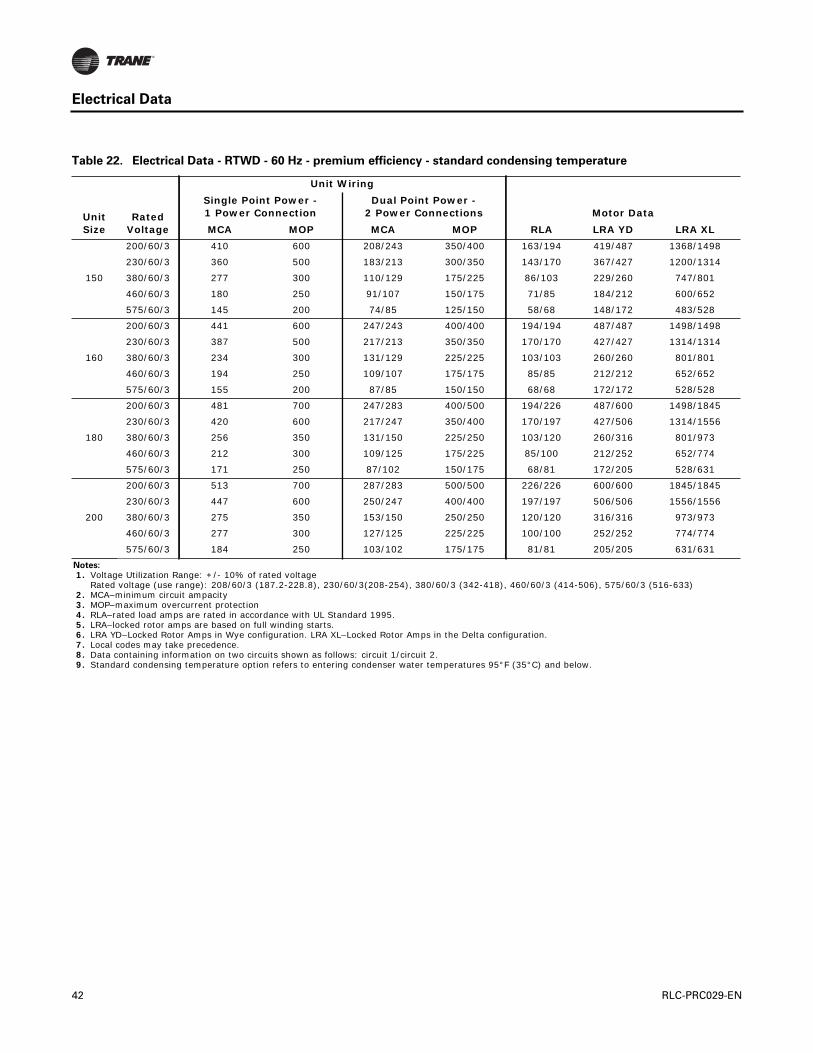
Electrical Data
Table 22. Electrical Data - RTWD - 60 Hz - premium efficiency - standard condensing temperature
Unit Size
Rated Voltage
Unit Wiring
Single Point Power - 1 Power Connection
Dual Point Power -2 Power Connections Motor Data
MCA MOP MCA MOP RLA LRA YD LRA XL
150
200/60/3 410 600 208/243 350/400 163/194 419/487 1368/1498
230/60/3 360 500 183/213 300/350 143/170 367/427 1200/1314
380/60/3 277 300 110/129 175/225 86/103 229/260 747/801
460/60/3 180 250 91/107 150/175 71/85 184/212 600/652
575/60/3 145 200 74/85 125/150 58/68 148/172 483/528
160
200/60/3 441 600 247/243 400/400 194/194 487/487 1498/1498
230/60/3 387 500 217/213 350/350 170/170 427/427 1314/1314
380/60/3 234 300 131/129 225/225 103/103 260/260 801/801
460/60/3 194 250 109/107 175/175 85/85 212/212 652/652
575/60/3 155 200 87/85 150/150 68/68 172/172 528/528
180
200/60/3 481 700 247/283 400/500 194/226 487/600 1498/1845
230/60/3 420 600 217/247 350/400 170/197 427/506 1314/1556
380/60/3 256 350 131/150 225/250 103/120 260/316 801/973
460/60/3 212 300 109/125 175/225 85/100 212/252 652/774
575/60/3 171 250 87/102 150/175 68/81 172/205 528/631
200
200/60/3 513 700 287/283 500/500 226/226 600/600 1845/1845
230/60/3 447 600 250/247 400/400 197/197 506/506 1556/1556
380/60/3 275 350 153/150 250/250 120/120 316/316 973/973
460/60/3 277 300 127/125 225/225 100/100 252/252 774/774
575/60/3 184 250 103/102 175/175 81/81 205/205 631/631
Notes:
1. Voltage Utilization Range: +/- 10% of rated voltage Rated voltage (use range): 208/60/3 (187.2-228.8), 230/60/3(208-254), 380/60/3 (342-418), 460/60/3 (414-506), 575/60/3 (516-633)
2. MCA–minimum circuit ampacity 3. MOP–maximum overcurrent protection 4. RLA–rated load amps are rated in accordance with UL Standard 1995. 5. LRA–locked rotor amps are based on full winding starts. 6. LRA YD–Locked Rotor Amps in Wye configuration. LRA XL–Locked Rotor Amps in the Delta configuration. 7. Local codes may take precedence. 8. Data containing information on two circuits shown as follows: circuit 1/circuit 2. 9. Standard condensing temperature option refers to entering condenser water temperatures 95°F (35°C) and below.
42 RLC-PRC029-EN
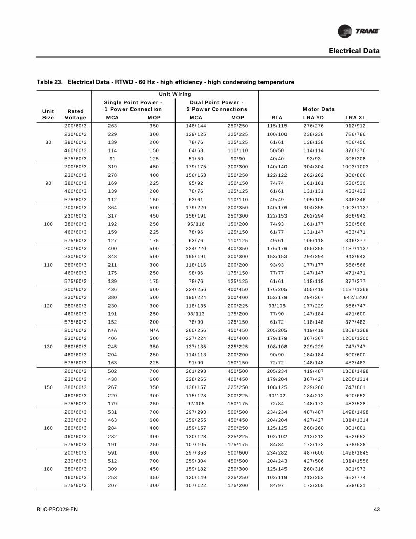
Electrical Data
Table 23. Electrical Data - RTWD - 60 Hz - high efficiency - high condensing temperature
Unit Size
Rated Voltage
Unit Wiring
Single Point Power - 1 Power Connection
Dual Point Power -2 Power Connections Motor Data
MCA MOP MCA MOP RLA LRA YD LRA XL
80
200/60/3 263 350 148/144 250/250 115/115 276/276 912/912
230/60/3 229 300 129/125 225/225 100/100 238/238 786/786
380/60/3 139 200 78/76 125/125 61/61 138/138 456/456
460/60/3 114 150 64/63 110/110 50/50 114/114 376/376
575/60/3 91 125 51/50 90/90 40/40 93/93 308/308
90
200/60/3 319 450 179/175 300/300 140/140 304/304 1003/1003
230/60/3 278 400 156/153 250/250 122/122 262/262 866/866
380/60/3 169 225 95/92 150/150 74/74 161/161 530/530
460/60/3 139 200 78/76 125/125 61/61 131/131 433/433
575/60/3 112 150 63/61 110/110 49/49 105/105 346/346
100
200/60/3 364 500 179/220 300/350 140/176 304/355 1003/1137
230/60/3 317 450 156/191 250/300 122/153 262/294 866/942
380/60/3 192 250 95/116 150/200 74/93 161/177 530/566
460/60/3 159 225 78/96 125/150 61/77 131/147 433/471
575/60/3 127 175 63/76 110/125 49/61 105/118 346/377
110
200/60/3 400 500 224/220 400/350 176/176 355/355 1137/1137
230/60/3 348 500 195/191 300/300 153/153 294/294 942/942
380/60/3 211 300 118/116 200/200 93/93 177/177 566/566
460/60/3 175 250 98/96 175/150 77/77 147/147 471/471
575/60/3 139 175 78/76 125/125 61/61 118/118 377/377
120
200/60/3 436 600 224/256 400/450 176/205 355/419 1137/1368
230/60/3 380 500 195/224 300/400 153/179 294/367 942/1200
380/60/3 230 300 118/135 200/225 93/108 177/229 566/747
460/60/3 191 250 98/113 175/200 77/90 147/184 471/600
575/60/3 152 200 78/90 125/150 61/72 118/148 377/483
130
200/60/3 N/A N/A 260/256 450/450 205/205 419/419 1368/1368
230/60/3 406 500 227/224 400/400 179/179 367/367 1200/1200
380/60/3 245 350 137/135 225/225 108/108 229/229 747/747
460/60/3 204 250 114/113 200/200 90/90 184/184 600/600
575/60/3 163 225 91/90 150/150 72/72 148/148 483/483
150
200/60/3 502 700 261/293 450/500 205/234 419/487 1368/1498
230/60/3 438 600 228/255 400/450 179/204 367/427 1200/1314
380/60/3 267 350 138/157 225/250 108/125 229/260 747/801
460/60/3 220 300 115/128 200/225 90/102 184/212 600/652
575/60/3 179 250 92/105 150/175 72/84 148/172 483/528
160
200/60/3 531 700 297/293 500/500 234/234 487/487 1498/1498
230/60/3 463 600 259/255 450/450 204/204 427/427 1314/1314
380/60/3 284 400 159/157 250/250 125/125 260/260 801/801
460/60/3 232 300 130/128 225/225 102/102 212/212 652/652
575/60/3 191 250 107/105 175/175 84/84 172/172 528/528
180
200/60/3 591 800 297/353 500/600 234/282 487/600 1498/1845
230/60/3 512 700 259/304 450/500 204/243 427/506 1314/1556
380/60/3 309 450 159/182 250/300 125/145 260/316 801/973
460/60/3 253 350 130/149 225/250 102/119 212/252 652/774
575/60/3 207 300 107/122 175/200 84/97 172/205 528/631
RLC-PRC029-EN 43

Electrical Data
200
200/60/3 621 800 347/343 600/600 274/274 600/600 1845/1845
230/60/3 551 700 308/304 500/500 243/243 506/506 1556/1556
380/60/3 327 450 183/180 300/300 144/144 316/316 973/973
460/60/3 270 350 151/149 250/250 119/119 252/252 774/774
575/60/3 220 300 123/122 200/200 97/97 205/205 631/631
220
200/60/3 702 1000 357/415 600/700 282/332 600/701 1845/2156
230/60/3 608 800 308/362 500/600 243/289 506/571 1556/1756
380/60/3 373 500 184/225 300/400 145/180 316/345 973/1060
460/60/3 303 400 151/182 250/300 119/145 252/285 774/878
575/60/3 244 350 123/145 200/250 97/116 205/229 631/705
250
200/60/3 752 1000 420/415 700/700 332/332 701/701 2156/2156
230/60/3 654 800 365/362 600/600 289/289 571/571 1756/1756
380/60/3 408 500 228/225 400/400 180/180 345/345 1060/1060
460/60/3 329 450 184/182 300/300 145/145 285/285 878/878
575/60/3 263 350 147/145 250/250 116/116 229/229 705/705
Notes:
1. Voltage Utilization Range: +/- 10% of rated voltage Rated voltage (use range): 208/60/3 (187.2-228.8), 230/60/3(208-254), 380/60/3 (342-418), 460/60/3 (414-506), 575/60/3 (516-633)MCA–minimum circuit ampacity
2. MOP–maximum overcurrent protection 3. RLA–rated load amps are rated in accordance with UL Standard 1995. 4. LRA–locked rotor amps are based on full winding starts. 5. LRA YD–Locked Rotor Amps in Wye configuration. LRA XL–Locked Rotor Amps in the Delta configuration. 6. Local codes may take precedence. 7. Data containing information on two circuits shown as follows: circuit 1/circuit 2. 8. High condensing temperature option refers to entering condenser water temperatures above 95°F (35°C).
Table 23. Electrical Data - RTWD - 60 Hz - high efficiency - high condensing temperature (continued)
Unit Size
Rated Voltage
Unit Wiring
Single Point Power - 1 Power Connection
Dual Point Power -2 Power Connections Motor Data
MCA MOP MCA MOP RLA LRA YD LRA XL
44 RLC-PRC029-EN

Electrical Data
Table 24. Electrical Data - RTWD - 60 Hz - premium efficiency - high condensing temperature
Unit Size
Rated Voltage
Unit Wiring
Single Point Power - 1 Power Connection
Dual Point Power -2 Power Connections Motor Data
MCA MOP MCA MOP RLA LRA YD LRA XL
150
200/60/3 498 700 252/295 400/500 198/236 419/487 1368/1498
230/60/3 430 600 219/254 350/450 172/203 367/427 1200/1314
380/60/3 266 350 138/155 225/250 108/124 229/260 747/801
460/60/3 218 300 112/128 175/225 88/102 184/212 600/652
575/60/3 178 250 91/105 150/175 71/84 148/172 483/528
160
200/60/3 536 700 300/295 500/500 236/236 487/487 1498
230/60/3 461 600 258/254 450/450 203/203 427/427 1314/1314
380/60/3 282 400 158/155 250/250 124/124 260/260 801/801
460/60/3 232 300 130/128 225/225 102/102 212/212 652/652
575/60/3 191 250 107/105 175/175 84/84 172/172 528/528
180
200/60/3 583 800 300/343 500/600 236/274 487/600 1498/1845
230/60/3 511 700 258/304 450/500 203/243 427/506 1314/1556
380/60/3 307 450 158/180 250/300 124/144 260/316 801/973
460/60/3 253 350 130/149 225/250 102/119 212/252 652/774
575/60/3 207 300 107/122 175/200 84/97 172/205 528/631
200
200/60/3 621 800 347/343 600/600 274/274 600/600 1845/1845
230/60/3 551 700 308/304 500/500 243/243 506/506 1556/1556
380/60/3 327 450 183/180 300/300 144/144 316/316 973/973
460/60/3 270 350 151/149 250/250 119/119 252/252 774/774
575/60/3 220 300 123/122 200/200 97/97 205/205 631/631
Notes:
1. Voltage Utilization Range: +/- 10% of rated voltage Rated voltage (use range): 208/60/3 (187.2-228.8), 230/60/3(208-254), 380/60/3 (342-418), 460/60/3 (414-506), 575/60/3 (516-633)
2. MCA–minimum circuit ampacity 3. MOP–maximum overcurrent protection 4. RLA–rated load amps are rated in accordance with UL Standard 1995. 5. LRA–locked rotor amps are based on full winding starts. 6. LRA YD–Locked Rotor Amps in Wye configuration. LRA XL–Locked Rotor Amps in the Delta configuration. 7. Local codes may take precedence. 8. Data containing information on two circuits shown as follows: circuit 1/circuit 2. 9. High condensing temperature option refers to entering condenser water temperatures above 95°F (35°C).
RLC-PRC029-EN 45

Electrical Data
Table 25. Electrical Data - RTUD - 60 Hz
Unit Size
Rated Voltage
Unit Wiring
Single Point Power - 1 Power Connection
Dual Point Power -2 Power Connections Motor Data
MCA MOP MCA MOP RLA LRA YD LRA XL
80
200/60/3 297 400 167/163 250/250 130/130 276/276 912/912
230/60/3 261 350 147/143 250/250 114/114 238/238 786/786
380/60/3 158 225 89/87 150/150 69/69 138/138 456/456
460/60/3 131 175 74/72 125/125 57/57 114/114 376/376
575/60/3 105 150 59/58 100/100 46/46 93/93 308/308
90
200/60/3 353 500 198/194 350/300 155/155 304/304 1003/1003
230/60/3 299 400 168/164 250/250 131/131 262/262 866/866
380/60/3 185 250 104/102 175/175 81/81 161/161 530/530
460/60/3 153 200 86/84 150/150 67/67 131/131 433/433
575/60/3 123 175 69/68 110/110 54/54 105/105 346/346
100
200/60/3 400 500 198/240 350/400 155/192 304/355 1003/1137
230/60/3 344 500 168/209 250/350 131/167 262/294 866/942
380/60/3 210 300 104/127 175/225 81/101 161/177 530/566
460/60/3 174 250 86/105 150/175 67/84 131/147 433/471
575/60/3 140 200 69/84 110/150 54/67 105/118 346/377
110
200/60/3 437 600 245/240 400/400 192/192 355/355 1137/1137
230/60/3 380 500 213/209 350/350 167/167 294/294 942/942
380/60/3 230 300 129/127 225/225 101/101 177/177 566/566
460/60/3 191 250 107/105 175/175 84/84 147/147 471/471
575/60/3 153 200 86/84 150/150 67/67 118/118 377/377
120
200/60/3 447 600 245/250 400/450 192/200 355/419 1137/1368
230/60/3 421 600 213/250 350/450 167/200 294/367 942/1200
380/60/3 255 350 129/152 225/250 101/121 177/229 566/747
460/60/3 211 300 107/125 175/225 84/100 147/184 471/600
575/60/3 169 225 86/100 150/175 67/80 118/148 377/483
130
200/60/3 455 600 255/250 450/450 200/200 419/419 1368/1368
230/60/3 454 600 254/250 450/450 200/200 367/367 1200/1200
380/60/3 275 350 154/152 250/250 121/121 229/229 747/747
460/60/3 227 300 127/125 225/225 100/100 184/184 600/600
575/60/3 182 250 102/100 175/175 80/80 148/148 483/483
150
200/60/3 542 800 255/338 450/600 200/270 419/487 1368/1498
230/60/3 498 700 254/294 450/500 200/235 367/427 1200/1314
380/60/3 301 400 154/178 250/300 121/142 229/260 747/801
460/60/3 250 350 127/148 225/250 100/118 184/212 600/652
575/60/3 199 250 102/118 175/200 80/84 148/172 483/528
160
200/60/3 612 800 342/338 600/600 270/270 487/487 1498/1498
230/60/3 553 700 298/294 500/500 235/235 427/427 1314/1314
380/60/3 322 450 180/178 300/300 142/142 260/260 801/801
460/60/3 268 350 150/148 250/250 118/118 212/212 652/652
575/60/3 213 300 119/118 200/200 94/94 172/172 528/528
180
200/60/3 675 800 342/400 600/700 270/320 487/600 1498/1845
230/60/3 587 800 298/348 500/600 235/278 427/506 1314/1556
380/60/3 355 500 180/210 300/350 142/168 260/316 801/973
460/60/3 284 400 150/164 250/250 118/131 212/252 652/774
575/60/3 235 300 119/139 200/225 94/111 172/205 528/631
46 RLC-PRC029-EN
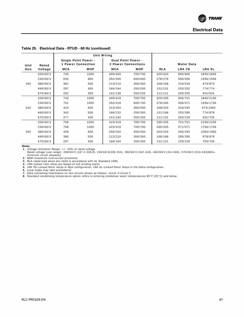
Electrical Data
200
200/60/3 725 1000 405/400 700/700 320/320 600/600 1845/1845
230/60/3 630 800 352/345 600/600 278/278 506/506 1556/1556
380/60/3 381 500 213/210 350/350 168/168 316/316 973/973
460/60/3 297 400 166/164 250/250 131/131 252/252 774/774
575/60/3 252 350 141/139 250/225 111/111 205/205 631/631
220
200/60/3 743 1000 405/419 700/700 320/335 600/701 1845/2156
230/60/3 701 1000 352/419 600/700 278/335 506/571 1556/1756
380/60/3 424 600 213/254 350/450 168/203 316/345 973/1060
460/60/3 343 500 166/210 250/350 131/168 252/285 774/878
575/60/3 277 400 141/164 250/250 111/131 205/229 631/705
250
200/60/3 758 1000 423/419 700/700 335/335 701/701 2156/2156
230/60/3 758 1000 423/419 700/700 335/335 571/571 1756/1756
380/60/3 459 600 256/254 450/450 203/203 345/345 1060/1060
460/60/3 380 500 212/210 350/350 168/168 285/285 878/878
575/60/3 297 400 166/164 250/250 131/131 229/229 705/705
Notes:
1. Voltage Utilization Range: +/- 10% of rated voltage Rated voltage (use range): 208/60/3 (187.2-228.8), 230/60/3(208-254), 380/60/3 (342-418), 460/60/3 (414-506), 575/60/3 (516-633)MCA–minimum circuit ampacity
2. MOP–maximum overcurrent protection 3. RLA–rated load amps are rated in accordance with UL Standard 1995. 4. LRA–locked rotor amps are based on full winding starts. 5. LRA YD–Locked Rotor Amps in Wye configuration. LRA XL–Locked Rotor Amps in the Delta configuration. 6. Local codes may take precedence. 7. Data containing information on two circuits shown as follows: circuit 1/circuit 2. 8. Standard condensing temperature option refers to entering condenser water temperatures 95°F (35°C) and below.
Table 25. Electrical Data - RTUD - 60 Hz (continued)
Unit Size
Rated Voltage
Unit Wiring
Single Point Power - 1 Power Connection
Dual Point Power -2 Power Connections Motor Data
MCA MOP MCA MOP RLA LRA YD LRA XL
RLC-PRC029-EN 47
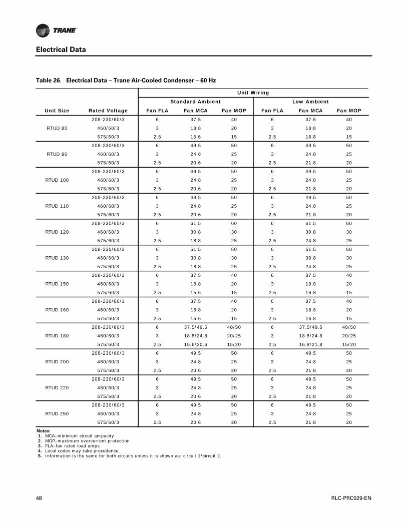
Electrical Data
Table 26. Electrical Data – Trane Air-Cooled Condenser – 60 Hz
Unit Wiring
Standard Ambient Low Ambient
Unit Size Rated Voltage Fan FLA Fan MCA Fan MOP Fan FLA Fan MCA Fan MOP
RTUD 80
208-230/60/3 6 37.5 40 6 37.5 40
460/60/3 3 18.8 20 3 18.8 20
575/60/3 2.5 15.6 15 2.5 16.8 15
RTUD 90
208-230/60/3 6 49.5 50 6 49.5 50
460/60/3 3 24.8 25 3 24.8 25
575/60/3 2.5 20.6 20 2.5 21.8 20
RTUD 100
208-230/60/3 6 49.5 50 6 49.5 50
460/60/3 3 24.8 25 3 24.8 25
575/60/3 2.5 20.6 20 2.5 21.8 20
RTUD 110
208-230/60/3 6 49.5 50 6 49.5 50
460/60/3 3 24.8 25 3 24.8 25
575/60/3 2.5 20.6 20 2.5 21.8 20
RTUD 120
208-230/60/3 6 61.5 60 6 61.5 60
460/60/3 3 30.8 30 3 30.8 30
575/60/3 2.5 18.8 25 2.5 24.8 25
RTUD 130
208-230/60/3 6 61.5 60 6 61.5 60
460/60/3 3 30.8 30 3 30.8 30
575/60/3 2.5 18.8 25 2.5 24.8 25
RTUD 150
208-230/60/3 6 37.5 40 6 37.5 40
460/60/3 3 18.8 20 3 18.8 20
575/60/3 2.5 15.6 15 2.5 16.8 15
RTUD 160
208-230/60/3 6 37.5 40 6 37.5 40
460/60/3 3 18.8 20 3 18.8 20
575/60/3 2.5 15.6 15 2.5 16.8 15
RTUD 180
208-230/60/3 6 37.5/49.5 40/50 6 37.5/49.5 40/50
460/60/3 3 18.8/24.8 20/25 3 18.8/24.8 20/25
575/60/3 2.5 15.6/20.6 15/20 2.5 16.8/21.8 15/20
RTUD 200
208-230/60/3 6 49.5 50 6 49.5 50
460/60/3 3 24.8 25 3 24.8 25
575/60/3 2.5 20.6 20 2.5 21.8 20
RTUD 220
208-230/60/3 6 49.5 50 6 49.5 50
460/60/3 3 24.8 25 3 24.8 25
575/60/3 2.5 20.6 20 2.5 21.8 20
RTUD 250
208-230/60/3 6 49.5 50 6 49.5 50
460/60/3 3 24.8 25 3 24.8 25
575/60/3 2.5 20.6 20 2.5 21.8 20
Notes:
1. MCA–minimum circuit ampacity 2. MOP–maximum overcurrent protection 3. FLA–fan rated load amps 4. Local codes may take precedence. 5. Information is the same for both circuits unless it is shown as: circuit 1/circuit 2.
48 RLC-PRC029-EN
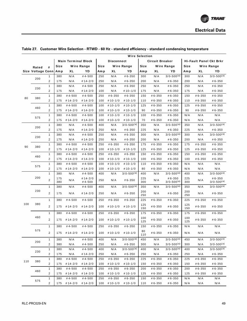
Electrical Data
Table 27. Customer Wire Selection - RTWD - 60 Hz - standard efficiency - standard condensing temperature
SizeRated
Voltage#
Conn
Wire Selection
Main Terminal Block Disconnect Circuit Breaker Hi-Fault Panel Ckt Brkr
Size Wire Range Size Wire Range Size Wire Range Size Wire Range
Amp XL YD Amp XL YD Amp XL YD Amp XL YD
80
2001 380 N/A #4-500 250 N/A #6-350 300 N/A 3/0-500(a) 300 N/A 3/0-500(a)
2 175 N/A #14-2/0 250 N/A #6-350 200 N/A #6-350 200 N/A #6-350
2301 380 N/A #4-500 250 N/A #6-350 250 N/A #6-350 250 N/A #6-350
2 175 N/A #14-2/0 100 N/A #10–1/0 175 N/A #6-350 175 N/A #6-350
3801 380 #4-500 #4-500 250 #6-350 #6-350 150 #6-350 #6-350 150 #6-350 #6-350
2 175 #14-2/0 #14-2/0 100 #10-1/0 #10-1/0 110 #6-350 #6-350 110 #6-350 #6-350
4601 380 #4-500 #4-500 100 #10-1/0 #10-1/0 125 #6-350 #6-350 125 #6-350 #6-350
2 175 #14-2/0 #14-2/0 100 #10-1/0 #10-1/0 90 #6-350 #6-350 90 #6-350 #6-350
5751 380 #4-500 #4-500 100 #10-1/0 #10-1/0 100 #6-350 #6-350 N/A N/A N/A
2 175 #14-2/0 #14-2/0 100 #10-1/0 #10-1/0 70 #6-350 #6-350 N/A N/A N/A
90
2001 380 N/A #4-500 400 N/A 3/0-500(a) 350 N/A 3/0-500(a) 350 N/A 3/0-500(a)
2 175 N/A #14-2/0 250 N/A #6-350 225 N/A #6-350 225 N/A #6-350
2301 380 N/A #4-500 250 N/A #6-350 300 N/A 3/0-500(a) 300 N/A 3/0-500(a)
2 175 N/A #14-2/0 250 N/A #6-350 200 N/A #6-350 200 N/A #6-350
3801 380 #4-500 #4-500 250 #6-350 #6-350 175 #6-350 #6-350 175 #6-350 #6-350
2 175 #14-2/0 #14-2/0 100 #10-1/0 #10-1/0 125 #6-350 #6-350 125 #6-350 #6-350
4601 380 #4-500 #4-500 250 #6-350 #6-350 150 #6-350 #6-350 150 #6-350 #6-350
2 175 #14-2/0 #14-2/0 100 #10-1/0 #10-1/0 100 #6-350 #6-350 100 #6-350 #6-350
5751 380 #4-500 #4-500 100 #10-1/0 #10-1/0 110 #6-350 #6-350 N/A N/A N/A
2 175 #14-2/0 #14-2/0 100 #10-1/0 #10-1/0 80 #6-350 #6-350 N/A N/A N/A
100
2001 380 N/A #4-500 400 N/A 3/0-500(a) 400 N/A 3/0-500(a) 400 N/A 3/0-500(a)
2175380
N/A#14-2/0#4-500
250 N/A #6-350225300
N/A#6-350
3/0-500(a)225300
N/A#6-350
3/0-500(a)
2301 380 N/A #4-500 400 N/A 3/0-500(a) 350 N/A 3/0-500(a) 350 N/A 3/0-500(a)
2 175 N/A #14-2/0 250 N/A #6-350200250
N/A #6-350200250
N/A #6-350
3801 380 #4-500 #4-500 250 #6-350 #6-350 225 #6-350 #6-350 225 #6-350 #6-350
2 175 #14-2/0 #14-2/0 100 #10-1/0 #10-1/0125150
#6-350 #6-350125150
#6-350 #6-350
4601 380 #4-500 #4-500 250 #6-350 #6-350 175 #6-350 #6-350 175 #6-350 #6-350
2 175 #14-2/0 #14-2/0 100 #10-1/0 #10-1/0100125
#6-350 #6-350100125
#6-350 #6-350
5751 380 #4-500 #4-500 250 #6-350 #6-350 150 #6-350 #6-350 N/A N/A N/A
2 175 #14-2/0 #14-2/0 100 #10-1/0 #10-1/080110
#6-350 #6-350 N/A N/A N/A
110
2001 380 N/A #4-500 400 N/A 3/0-500(a) 450 N/A 3/0-500(a) 450 N/A 3/0-500(a)
2 380 N/A #4-500 250 N/A #6-350 300 N/A 3/0-500(a) 300 N/A 3/0-500(a)
2301 380 N/A #4-500 400 N/A 3/0-500(a) 400 N/A 3/0-500(a) 400 N/A 3/0-500(a)
2 175 N/A #14-2/0 250 N/A #6-350 250 N/A #6-350 250 N/A #6-350
3801 380 #4-500 #4-500 250 #6-350 #6-350 225 #6-350 #6-350 225 #6-350 #6-350
2 175 #14-2/0 #14-2/0 100 #10-1/0 #10-1/0 150 #6-350 #6-350 150 #6-350 #6-350
4601 380 #4-500 #4-500 250 #6-350 #6-350 200 #6-350 #6-350 200 #6-350 #6-350
2 175 #14-2/0 #14-2/0 100 #10-1/0 #10-1/0 125 #6-350 #6-350 125 #6-350 #6-350
5751 380 #4-500 #4-500 250 #6-350 #6-350 150 #6-350 #6-350 N/A N/A N/A
2 175 #14-2/0 #14-2/0 100 #10-1/0 #10-1/0 110 #6-350 #6-350 N/A N/A N/A
RLC-PRC029-EN 49
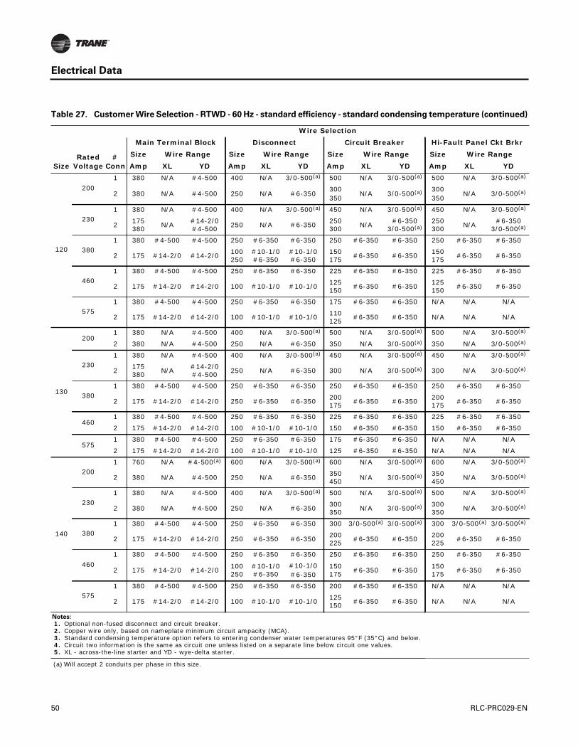
Electrical Data
120
200
1 380 N/A #4-500 400 N/A 3/0-500(a) 500 N/A 3/0-500(a) 500 N/A 3/0-500(a)
2 380 N/A #4-500 250 N/A #6-350300350
N/A 3/0-500(a) 300350
N/A 3/0-500(a)
2301 380 N/A #4-500 400 N/A 3/0-500(a) 450 N/A 3/0-500(a) 450 N/A 3/0-500(a)
2175380
N/A#14-2/0#4-500
250 N/A #6-350250300
N/A#6-350
3/0-500(a)250300
N/A#6-350
3/0-500(a)
3801 380 #4-500 #4-500 250 #6-350 #6-350 250 #6-350 #6-350 250 #6-350 #6-350
2 175 #14-2/0 #14-2/0100250
#10-1/0#6-350
#10-1/0#6-350
150175
#6-350 #6-350150175
#6-350 #6-350
4601 380 #4-500 #4-500 250 #6-350 #6-350 225 #6-350 #6-350 225 #6-350 #6-350
2 175 #14-2/0 #14-2/0 100 #10-1/0 #10-1/0125150
#6-350 #6-350125150
#6-350 #6-350
5751 380 #4-500 #4-500 250 #6-350 #6-350 175 #6-350 #6-350 N/A N/A N/A
2 175 #14-2/0 #14-2/0 100 #10-1/0 #10-1/0110125
#6-350 #6-350 N/A N/A N/A
130
2001 380 N/A #4-500 400 N/A 3/0-500(a) 500 N/A 3/0-500(a) 500 N/A 3/0-500(a)
2 380 N/A #4-500 250 N/A #6-350 350 N/A 3/0-500(a) 350 N/A 3/0-500(a)
2301 380 N/A #4-500 400 N/A 3/0-500(a) 450 N/A 3/0-500(a) 450 N/A 3/0-500(a)
2175380
N/A#14-2/0#4-500
250 N/A #6-350 300 N/A 3/0-500(a) 300 N/A 3/0-500(a)
3801 380 #4-500 #4-500 250 #6-350 #6-350 250 #6-350 #6-350 250 #6-350 #6-350
2 175 #14-2/0 #14-2/0 250 #6-350 #6-350200175
#6-350 #6-350200175
#6-350 #6-350
4601 380 #4-500 #4-500 250 #6-350 #6-350 225 #6-350 #6-350 225 #6-350 #6-350
2 175 #14-2/0 #14-2/0 100 #10-1/0 #10-1/0 150 #6-350 #6-350 150 #6-350 #6-350
5751 380 #4-500 #4-500 250 #6-350 #6-350 175 #6-350 #6-350 N/A N/A N/A
2 175 #14-2/0 #14-2/0 100 #10-1/0 #10-1/0 125 #6-350 #6-350 N/A N/A N/A
140
2001 760 N/A #4-500(a) 600 N/A 3/0-500(a) 600 N/A 3/0-500(a) 600 N/A 3/0-500(a)
2 380 N/A #4-500 250 N/A #6-350350450
N/A 3/0-500(a) 350450
N/A 3/0-500(a)
2301 380 N/A #4-500 400 N/A 3/0-500(a) 500 N/A 3/0-500(a) 500 N/A 3/0-500(a)
2 380 N/A #4-500 250 N/A #6-350300350
N/A 3/0-500(a) 300350
N/A 3/0-500(a)
3801 380 #4-500 #4-500 250 #6-350 #6-350 300 3/0-500(a) 3/0-500(a) 300 3/0-500(a) 3/0-500(a)
2 175 #14-2/0 #14-2/0 250 #6-350 #6-350200225
#6-350 #6-350200225
#6-350 #6-350
460
1 380 #4-500 #4-500 250 #6-350 #6-350 250 #6-350 #6-350 250 #6-350 #6-350
2 175 #14-2/0 #14-2/0100250
#10-1/0#6-350
#10-1/0#6-350
150175
#6-350 #6-350150175
#6-350 #6-350
5751 380 #4-500 #4-500 250 #6-350 #6-350 200 #6-350 #6-350 N/A N/A N/A
2 175 #14-2/0 #14-2/0 100 #10-1/0 #10-1/0125150
#6-350 #6-350 N/A N/A N/A
Notes:
1. Optional non-fused disconnect and circuit breaker. 2. Copper wire only, based on nameplate minimum circuit ampacity (MCA). 3. Standard condensing temperature option refers to entering condenser water temperatures 95°F (35°C) and below. 4. Circuit two information is the same as circuit one unless listed on a separate line below circuit one values. 5. XL - across-the-line starter and YD - wye-delta starter.
(a) Will accept 2 conduits per phase in this size.
Table 27. Customer Wire Selection - RTWD - 60 Hz - standard efficiency - standard condensing temperature (continued)
SizeRated
Voltage#
Conn
Wire Selection
Main Terminal Block Disconnect Circuit Breaker Hi-Fault Panel Ckt Brkr
Size Wire Range Size Wire Range Size Wire Range Size Wire Range
Amp XL YD Amp XL YD Amp XL YD Amp XL YD
50 RLC-PRC029-EN

Electrical Data
Table 28. Customer Wire Selection - RTWD - 60 Hz - high efficiency - standard condensing temperature
SizeRated
Voltage#
Conn
Wire Selection
Main Terminal Block Disconnect Circuit Breaker Hi-Fault Panel Ckt Brkr
Size Wire Range Size Wire Range Size Wire Range Size Wire Range
Amp XL YD Amp XL YD Amp XL YD Amp XL YD
80
2001 380 N/A #4-500 250 N/A #6-350 300 N/A 3/0-500(a) 300 N/A 3/0-500(a)
2 175 N/A #14-2/0 250 N/A #6-350 200 N/A #6-350 200 N/A #6-350
2301 380 N/A #4-500 250 N/A #6-350 250 N/A #6-350 250 N/A #6-350
2 175 N/A #14-2/0 100 N/A #10-1/0 175 N/A #6-350 175 N/A #6-350
3801 380 #4-500 #4-500 250 #6-350 #6-350 150 #6-350 #6-350 150 #6-350 #6-350
2 175 #14-2/0 #14-2/0 100 #10-1/0 #10-1/0 110 #6-350 #6-350 110 #6-350 #6-350
4601 380 #4-500 #4-500 100 #10-1/0 #10-1/0 125 #6-350 #6-350 125 #6-350 #6-350
2 175 #14-2/0 #14-2/0 100 #10-1/0 #10-1/0 90 #6-350 #6-350 90 #6-350 #6-350
5751 380 #4-500 #4-500 100 #10-1/0 #10-1/0 100 #6-350 #6-350 N/A N/A N/A
2 175 #14-2/0 #14-2/0 100 #10-1/0 #10-1/0 70 #6-350 #6-350 N/A N/A N/A
90
2001 380 N/A #4-500 250 N/A #6-350 350 N/A 3/0-500(a) 350 N/A 3/0-500(a)
2 175 N/A #14-2/0 250 N/A #6-350 225 N/A #6-350 225 N/A #6-350
2301 380 N/A #4-500 250 N/A #6-350 300 N/A 3/0-500(a) 300 N/A 3/0-500(a)
2 175 N/A #14-2/0 250 N/A #6-350 200 N/A #6-350 200 N/A #6-350
3801 380 #4-500 #4-500 250 #6-350 #6-350 175 #6-350 #6-350 175 #6-350 #6-350
2 175 #14-2/0 #14-2/0 100 #10-1/0 #10-1/0 125 #6-350 #6-350 125 #6-350 #6-350
4601 380 #4-500 #4-500 250 #6-350 #6-350 150 #6-350 #6-350 150 #6-350 #6-350
2 175 #14-2/0 #14-2/0 100 #10-1/0 #10-1/0 100 #6-350 #6-350 100 #6-350 #6-350
5751 380 #4-500 #4-500 100 #10-1/0 #10-1/0 110 #6-350 #6-350 N/A N/A N/A
2 175 #14-2/0 #14-2/0 100 #10-1/0 #10-1/0 80 #6-350 #6-350 N/A N/A N/A
100
2001 380 N/A #4-500 400 N/A 3/0-500(a) 400 N/A 3/0-500(a) 400 N/A 3/0-500(a)
2 175 N/A #14-2/0 250 N/A #6-350225300
N/A#6-350
3/0-500(a)225300
N/A#6-350
3/0-500(a)
2301 380 N/A #4-500 250 N/A #6-350 350 N/A 3/0-500(a) 350 N/A 3/0-500(a)
2 175 N/A #14-2/0 250 N/A #6-350200250
N/A #6-350200250
N/A #6-350
3801 380 #4-500 #4-500 250 #6-350 #6-350 200 #6-350 #6-350 200 #6-350 #6-350
2 175 #14-2/0 #14-2/0 100 #10-1/0 #10-1/0125150
#6-350 #6-350125150
#6-350 #6-350
4601 380 #4-500 #4-500 250 #6-350 #6-350 175 #6-350 #6-350 175 #6-350 #6-350
2 175 #14-2/0 #14-2/0 100 #10-1/0 #10-1/0100125
#6-350 #6-350100125
#6-350 #6-350
5751 380 #4-500 #4-500 100 #10-1/0 #10-1/0 125 #6-350 #6-350 N/A N/A N/A
2 175 #14-2/0 #14-2/0 100 #10-1/0 #10-1/080100
#6-350 #6-350 N/A N/A N/A
110
2001 380 N/A #4-500 400 N/A 3/0-500(a) 450 N/A 3/0-500(a) 450 N/A 3/0-500(a)
2380175
N/A#4-500#14-2/0
250 N/A #6-350 300 N/A 3/0-500(a) 300 N/A 3/0-500(a)
2301 380 N/A #4-500 400 N/A 3/0-500(a) 350 N/A 3/0-500(a) 350 N/A 3/0-500(a)
2 175 N/A #14-2/0 250 N/A #6-350 250 N/A #6-350 250 N/A #6-350
3801 380 #4-500 #4-500 250 #6-350 #6-350 225 #6-350 #6-350 225 #6-350 #6-350
2 175 #14-2/0 #14-2/0 100 #10-1/0 #10-1/0 150 #6-350 #6-350 150 #6-350 #6-350
4601 380 #4-500 #4-500 250 #6-350 #6-350 175 #6-350 #6-350 175 #6-350 #6-350
2 175 #14-2/0 #14-2/0 100 #10-1/0 #10-1/0 125 #6-350 #6-350 125 #6-350 #6-350
5751 380 #4-500 #4-500 250 #6-350 #6-350 150 #6-350 #6-350 N/A N/A N/A
2 175 #14-2/0 #14-2/0 100 #10-1/0 #10-1/0 100 #6-350 #6-350 N/A N/A N/A
RLC-PRC029-EN 51

Electrical Data
120
200
1 760 N/A #4-500(a) 400 N/A 3/0-500(a) 500 N/A 3/0-500(a) 500 N/A 3/0-500(a)
2 380 N/A #4-500 250 N/A #6-350300350
N/A 3/0-500(a) 300350
N/A 3/0-500(a)
2301 380 N/A #4-500 400 N/A 3/0-500(a) 400 N/A 3/0-500(a) 400 N/A 3/0-500(a)
2 380 N/A #4-500 250 N/A #6-350250300
N/A#6-350
3/0-500(a)250300
N/A#6-350
3/0-500(a)
3801 380 #4-500 #4-500 250 #6-350 #6-350 250 #6-350 #6-350 250 #6-350 #6-350
2 175 #14-2/0 #14-2/0100250
#10-1/0#6-350
#10-1/0#6-350
150175
#6-350 #6-350150175
#6-350 #6-350
4601 380 #4-500 #4-500 250 #6-350 #6-350 200 #6-350 #6-350 200 #6-350 #6-350
2 175 #14-2/0 #14-2/0 100 #10-1/0 #10-1/0125150
#6-350 #6-350125150
#6-350 #6-350
5751 380 #4-500 #4-500 250 #6-350 #6-350 175 #6-350 #6-350 N/A N/A N/A
2 175 #14-2/0 #14-2/0 100 #10-1/0 #10-1/0100125
#6-350 #6-350 N/A N/A N/A
130
2001 380 N/A #4-500 400 N/A 3/0-500(a) 500 N/A 3/0-500(a) 500 N/A 3/0-500(a)
2 380 N/A #4-500 250 N/A #6-350 350 N/A 3/0-500(a) 350 N/A 3/0-500(a)
2301 380 N/A #4-500 400 N/A 3/0-500(a) 450 N/A 3/0-500(a) 450 N/A 3/0-500(a)
2 380 N/A #4-500 250 N/A #6-350 300 N/A 3/0-500(a) 300 N/A 3/0-500(a)
3801 380 #4-500 #4-500 250 #6-350 #6-350 250 #6-350 #6-350 250 #6-350 #6-350
2 175 #14-2/0 #14-2/0 250 #6-350 #6-350 175 #6-350 #6-350 175 #6-350 #6-350
4601 380 #4-500 #4-500 250 #6-350 #6-350 225 #6-350 #6-350 225 #6-350 #6-350
2 175 #14-2/0 #14-2/0 100 #10-1/0 #10-1/0 150 #6-350 #6-350 150 #6-350 #6-350
5751 380 #4-500 #4-500 250 #6-350 #6-350 175 #6-350 #6-350 N/A N/A N/A
2 175 #14-2/0 #14-2/0 100 #10-1/0 #10-1/0 125 #6-350 #6-350 N/A N/A N/A
150
2001 760 N/A #4–500(a) 600 N/A 3/0-500(a) 600 N/A 3/0-500(a) 600 N/A 3/0-500(a)
2 380 N/A #4–500 250 N/A #6-350350400
N/A 3/0-500(a) 350400
N/A 3/0-500(a)
2301 380 N/A #4–500 400 N/A 3/0-500(a) 500 N/A 3/0-500(a) 500 N/A 3/0-500(a)
2 380 N/A #4–500 250 N/A #6-350300350
N/A 3/0-500(a) 300350
N/A 3/0-500(a)
3801 380 #4-500 #4–500 250 #6-350 #6-350 300 3/0-500 3/0-500(a) 300 3/0-500 3/0-500(a)
2 175 #14-2/0 #14-2/0 250 #6-350 #6-350175225
#6-350 #6-350175225
#6-350 #6-350
4601 380 #4-500 #4–500 250 #6-350 #6-350 250 3/0-500(a) 3/0-500(a) 250 3/0-500(a) 3/0-500(a)
2 175 #14-2/0 #14-2/0 100 #10-1/0 #10-1/0150175
#6-350 #6-350150175
#6-350 #6-350
5751 175 #14-2/0 #14-2/0 250 #6-350 #6-350 200 #6-350 #6-350 N/A N/A N/A
2 175 #14-2/0 #14-2/0 100 #10-1/0 #10-1/0125150
#6-350 #6-350 N/A N/A N/A
Table 28. Customer Wire Selection - RTWD - 60 Hz - high efficiency - standard condensing temperature (continued)
SizeRated
Voltage#
Conn
Wire Selection
Main Terminal Block Disconnect Circuit Breaker Hi-Fault Panel Ckt Brkr
Size Wire Range Size Wire Range Size Wire Range Size Wire Range
Amp XL YD Amp XL YD Amp XL YD Amp XL YD
52 RLC-PRC029-EN
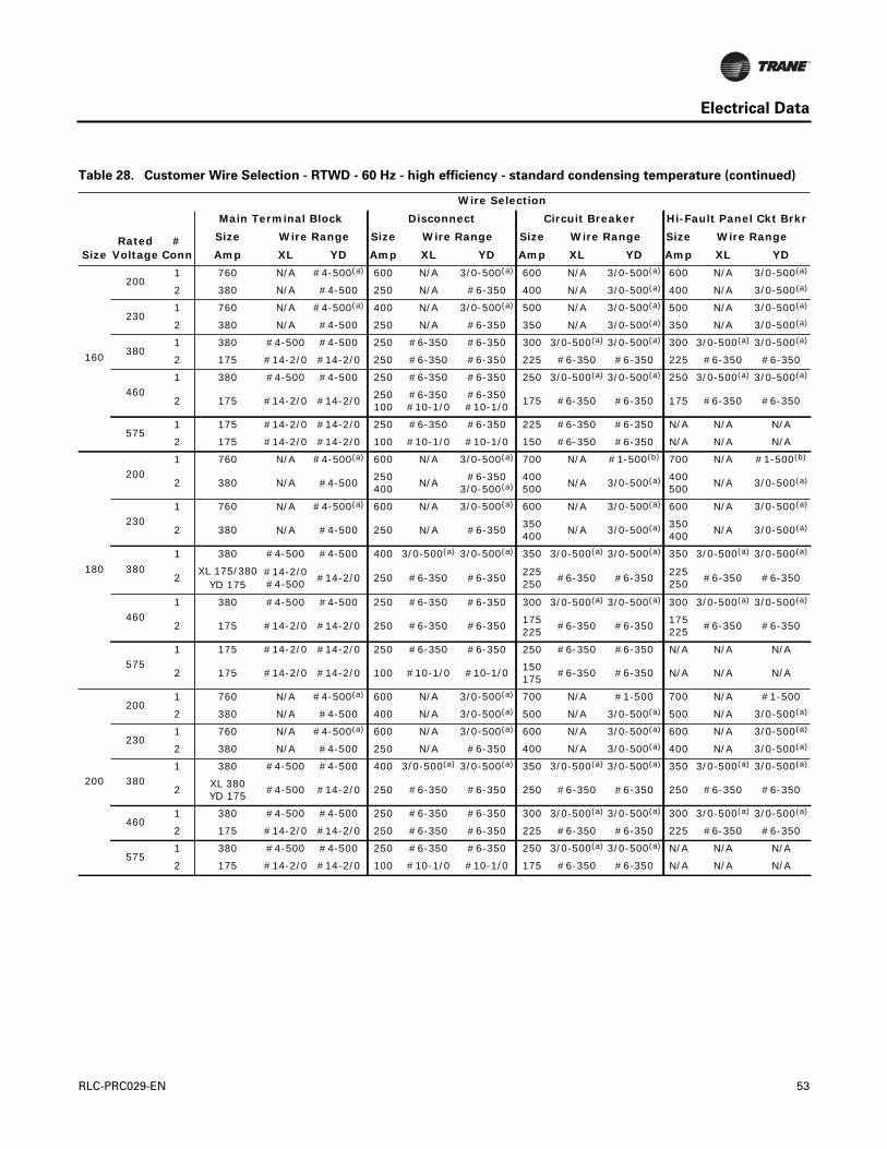
Electrical Data
160
2001 760 N/A #4-500(a) 600 N/A 3/0-500(a) 600 N/A 3/0-500(a) 600 N/A 3/0-500(a)
2 380 N/A #4-500 250 N/A #6-350 400 N/A 3/0-500(a) 400 N/A 3/0-500(a)
2301 760 N/A #4-500(a) 400 N/A 3/0-500(a) 500 N/A 3/0-500(a) 500 N/A 3/0-500(a)
2 380 N/A #4-500 250 N/A #6-350 350 N/A 3/0-500(a) 350 N/A 3/0-500(a)
3801 380 #4-500 #4-500 250 #6-350 #6-350 300 3/0-500(a) 3/0-500(a) 300 3/0-500(a) 3/0-500(a)
2 175 #14-2/0 #14-2/0 250 #6-350 #6-350 225 #6-350 #6-350 225 #6-350 #6-350
4601 380 #4-500 #4-500 250 #6-350 #6-350 250 3/0-500(a) 3/0-500(a) 250 3/0-500(a) 3/0-500(a)
2 175 #14-2/0 #14-2/0250100
#6-350#10-1/0
#6-350#10-1/0
175 #6-350 #6-350 175 #6-350 #6-350
5751 175 #14-2/0 #14-2/0 250 #6-350 #6-350 225 #6-350 #6-350 N/A N/A N/A
2 175 #14-2/0 #14-2/0 100 #10-1/0 #10-1/0 150 #6-350 #6-350 N/A N/A N/A
180
2001 760 N/A #4-500(a) 600 N/A 3/0-500(a) 700 N/A #1-500(b) 700 N/A #1-500(b)
2 380 N/A #4-500250400
N/A#6-350
3/0-500(a)400500
N/A 3/0-500(a) 400500
N/A 3/0-500(a)
2301 760 N/A #4-500(a) 600 N/A 3/0-500(a) 600 N/A 3/0-500(a) 600 N/A 3/0-500(a)
2 380 N/A #4-500 250 N/A #6-350350400
N/A 3/0-500(a) 350400
N/A 3/0-500(a)
380
1 380 #4-500 #4-500 400 3/0-500(a) 3/0-500(a) 350 3/0-500(a) 3/0-500(a) 350 3/0-500(a) 3/0-500(a)
2XL 175/380
YD 175#14-2/0#4-500
#14-2/0 250 #6-350 #6-350225250
#6-350 #6-350225250
#6-350 #6-350
4601 380 #4-500 #4-500 250 #6-350 #6-350 300 3/0-500(a) 3/0-500(a) 300 3/0-500(a) 3/0-500(a)
2 175 #14-2/0 #14-2/0 250 #6-350 #6-350175225
#6-350 #6-350175225
#6-350 #6-350
5751 175 #14-2/0 #14-2/0 250 #6-350 #6-350 250 #6-350 #6-350 N/A N/A N/A
2 175 #14-2/0 #14-2/0 100 #10-1/0 #10-1/0150175
#6-350 #6-350 N/A N/A N/A
200
2001 760 N/A #4-500(a) 600 N/A 3/0-500(a) 700 N/A #1-500 700 N/A #1-500
2 380 N/A #4-500 400 N/A 3/0-500(a) 500 N/A 3/0-500(a) 500 N/A 3/0-500(a)
2301 760 N/A #4-500(a) 600 N/A 3/0-500(a) 600 N/A 3/0-500(a) 600 N/A 3/0-500(a)
2 380 N/A #4-500 250 N/A #6-350 400 N/A 3/0-500(a) 400 N/A 3/0-500(a)
3801 380 #4-500 #4-500 400 3/0-500(a) 3/0-500(a) 350 3/0-500(a) 3/0-500(a) 350 3/0-500(a) 3/0-500(a)
2XL 380YD 175
#4-500 #14-2/0 250 #6-350 #6-350 250 #6-350 #6-350 250 #6-350 #6-350
4601 380 #4-500 #4-500 250 #6-350 #6-350 300 3/0-500(a) 3/0-500(a) 300 3/0-500(a) 3/0-500(a)
2 175 #14-2/0 #14-2/0 250 #6-350 #6-350 225 #6-350 #6-350 225 #6-350 #6-350
5751 380 #4-500 #4-500 250 #6-350 #6-350 250 3/0-500(a) 3/0-500(a) N/A N/A N/A
2 175 #14-2/0 #14-2/0 100 #10-1/0 #10-1/0 175 #6-350 #6-350 N/A N/A N/A
Table 28. Customer Wire Selection - RTWD - 60 Hz - high efficiency - standard condensing temperature (continued)
SizeRated
Voltage#
Conn
Wire Selection
Main Terminal Block Disconnect Circuit Breaker Hi-Fault Panel Ckt Brkr
Size Wire Range Size Wire Range Size Wire Range Size Wire Range
Amp XL YD Amp XL YD Amp XL YD Amp XL YD
RLC-PRC029-EN 53
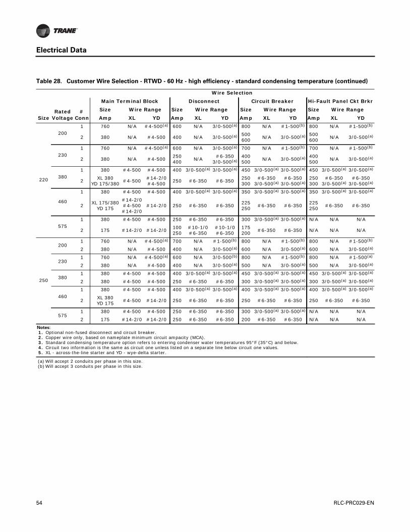
Electrical Data
220
2001 760 N/A #4-500(a) 600 N/A 3/0-500(a) 800 N/A #1-500(b) 800 N/A #1-500(b)
2 380 N/A #4-500 400 N/A 3/0-500(a) 500600
N/A 3/0-500(a) 500600
N/A 3/0-500(a)
2301 760 N/A #4-500(a) 600 N/A 3/0-500(a) 700 N/A #1-500(b) 700 N/A #1-500(b)
2 380 N/A #4-500250400
N/A#6-350
3/0-500(a)400500
N/A 3/0-500(a) 400500
N/A 3/0-500(a)
3801 380 #4-500 #4-500 400 3/0-500(a) 3/0-500(a) 450 3/0-500(a) 3/0-500(a) 450 3/0-500(a) 3/0-500(a)
2XL 380
YD 175/380#4-500
#14-2/0#4-500
250 #6-350 #6-350250300
#6-3503/0-500(a)
#6-3503/0-500(a)
250300
#6-3503/0-500(a)
#6-3503/0-500(a)
460
1 380 #4-500 #4-500 400 3/0-500(a) 3/0-500(a) 350 3/0-500(a) 3/0-500(a) 350 3/0-500(a) 3/0-500(a)
2XL 175/380
YD 175
#14-2/0#4-500#14-2/0
#14-2/0 250 #6-350 #6-350225250
#6-350 #6-350225250
#6-350 #6-350
5751 380 #4-500 #4-500 250 #6-350 #6-350 300 3/0-500(a) 3/0-500(a) N/A N/A N/A
2 175 #14-2/0 #14-2/0100250
#10-1/0#6-350
#10-1/0#6-350
175200
#6-350 #6-350 N/A N/A N/A
250
2001 760 N/A #4-500(a) 700 N/A #1-500(b) 800 N/A #1-500(b) 800 N/A #1-500(b)
2 380 N/A #4-500 400 N/A 3/0-500(a) 600 N/A 3/0-500(a) 600 N/A 3/0-500(a)
2301 760 N/A #4-500(a) 600 N/A 3/0-500(b) 800 N/A #1-500(b) 800 N/A #1-500(a)
2 380 N/A #4-500 400 N/A 3/0-500(a) 500 N/A 3/0-500(a) 500 N/A 3/0-500(a)
3801 380 #4-500 #4-500 400 3/0-500(a) 3/0-500(a) 450 3/0-500(a) 3/0-500(a) 450 3/0-500(a) 3/0-500(a)
2 380 #4-500 #4-500 250 #6-350 #6-350 300 3/0-500(a) 3/0-500(a) 300 3/0-500(a) 3/0-500(a)
4601 380 #4-500 #4-500 400 3/0-500(a) 3/0-500(a) 400 3/0-500(a) 3/0-500(a) 400 3/0-500(a) 3/0-500(a)
2XL 380YD 175
#4-500 #14-2/0 250 #6-350 #6-350 250 #6-350 #6-350 250 #6-350 #6-350
5751 380 #4-500 #4-500 250 #6-350 #6-350 300 3/0-500(a) 3/0-500(a) N/A N/A N/A
2 175 #14-2/0 #14-2/0 250 #6-350 #6-350 200 #6-350 #6-350 N/A N/A N/A
Notes:
1. Optional non-fused disconnect and circuit breaker. 2. Copper wire only, based on nameplate minimum circuit ampacity (MCA). 3. Standard condensing temperature option refers to entering condenser water temperatures 95°F (35°C) and below. 4. Circuit two information is the same as circuit one unless listed on a separate line below circuit one values. 5. XL - across-the-line starter and YD - wye-delta starter.
(a) Will accept 2 conduits per phase in this size.(b) Will accept 3 conduits per phase in this size.
Table 28. Customer Wire Selection - RTWD - 60 Hz - high efficiency - standard condensing temperature (continued)
SizeRated
Voltage#
Conn
Wire Selection
Main Terminal Block Disconnect Circuit Breaker Hi-Fault Panel Ckt Brkr
Size Wire Range Size Wire Range Size Wire Range Size Wire Range
Amp XL YD Amp XL YD Amp XL YD Amp XL YD
54 RLC-PRC029-EN

Electrical Data
Table 29. Customer Wire Selection - RTWD - 60 Hz - premium efficiency - standard condensing temperature
SizeRated
Voltage#
Conn
Wire Selection
Main Terminal Block Disconnect Circuit Breaker Hi-Fault Panel Ckt Brkr
Size Wire Range Size Wire Range Size Wire Range Size Wire Range
Amp XL YD Amp XL YD Amp XL YD Amp XL YD
150
2001 760 N/A #4-500(a) 600 N/A
3/0-#500(a) 600 N/A 3/0-500(a) 600 N/A 3/0-500(a)
2 380 N/A #4-500 250 N/A #6-350350400
N/A 3/0-500(a) 350400
N/A 3/0-500(a)
2301 380 N/A #4-500 400 N/A
3/0-#500(a) 500 N/A 3/0-500(a) 500 N/A 3/0-500(a)
2 380 N/A #4-500 250 N/A #6-350300350
N/A 3/0-500(a) 300350
N/A 3/0-500(a)
3801 380 #4-500 #4-500 250 #6-350 #6-350 300 3/0-500(a) 3/0-500(a) 300 3/0-500(a) 3/0-500(a)
2 175 #14-2/0 #14-2/0 250 #6-350 #6-350175225
#6-350 #6-350175225
#6-350 #6-350
4601 380 #4-500 #4-500 250 #6-350 #6-350 250 #6-350 #6-350 250 #6-350 #6-350
2 175 #14-2/0 #14-2/0 100 #10-1/0 #10-1/0150175
#6-350 #6-350150175
#6-350 #6-350
5751 175 #14-2/0 #14-2/0 250 #6-350 #6-350 200 #6-350 #6-350 N/A N/A N/A
2 175 #14-2/0 #14-2/0 100 #10-1/0 #10-1/0125150
#6-350 #6-350 N/A N/A N/A
160
2001 760 N/A #4-500(a) 600 N/A 3/0-500(a) 600 N/A 3/0-500(a) 600 N/A 3/0-500(a)
2 380 N/A #4-500 250 N/A #6-350 400 N/A 3/0-500(a) 400 N/A 3/0-500(a)
2301 760 N/A #4-500(a) 400 N/A 3/0-500(a) 500 N/A 3/0-500(a) 500 N/A 3/0-500(a)
2 380 N/A #4-500 250 N/A #6-350 350 N/A 3/0-500(a) 350 N/A 3/0-500(a)
3801 380 #4-500 #4-500 250 #6-350 #6-350 300 3/0-500(a) 3/0-500(a) 300 3/0-500(a) 3/0-500(a)
2 175 #14-2/0 #14-2/0 250 #6-350 #6-350 225 #6-350 #6-350 225 #6-350 #6-350
4601 380 #4-500 #4-500 250 #6-350 #6-350 250 3/0-500(a) 3/0-500(a) 250 3/0-500(a) 3/0-500(a)
2 175 #14-2/0 #14-2/0 100 #10-1/0 #10-1/0 175 #6-350 #6-350 175 #6-350 #6-350
5751 175 #14-2/0 #14-2/0 250 #6-350 #6-350 200 #6-350 #6-350 N/A N/A N/A
2 175 #14-2/0 #14-2/0 100 #10-1/0 #10-1/0 150 #6-350 #6-350 N/A N/A N/A
180
2001 760 N/A #4-500(a) 600 N/A 3/0-500(a) 700 N/A #1-500(b) 700 N/A #1-500(b)
2 380 N/A #4-500250400
N/A#6-350
3/0-500(a)400500
N/A 3/0-500(a) 400500
N/A 3/0-500(a)
2301 760 N/A #4-500(a) 600 N/A 3/0-500(a) 600 N/A 3/0-500(a) 600 N/A 3/0-500(a)
2 380 N/A #4-500 250 N/A #6-350350400
N/A 3/0-500(a) 350400
N/A 3/0-500(a)
380
1 380 #4-500 #4-500 400 3/0-500(a) 3/0-500(a) 350 3/0-500(a) 3/0-500(a) 350 3/0-500(a) 3/0-500(a)
2XL 175/380
YD 175#14-2/0#4-500
#14-2/0 250 #6-350 #6-350225250
#6-350 #6-350225250
#6-350 #6-350
4601 380 #4-500 #4-500 250 #6-350 #6-350 300 3/0-500(a) 3/0-500(a) 300 3/0-500(a) 3/0-500(a)
2 175 #14-2/0 #14-2/0100250
#10-1/0#6-350
#10-1/0#6-350
175225
#6-350 #6-350175225
#6-350 #6-350
5751 175 #14-2/0 #14-2/0 250 #6-350 #6-350 250 #6-350 #6-350 N/A N/A N/A
2 175 #14-2/0 #14-2/0 100 #10-1/0 #10-1/0150175
#6-350 #6-350 N/A N/A N/A
RLC-PRC029-EN 55

Electrical Data
200
2001 760 N/A #4-500(a) 600 N/A 3/0-500(a) 700 N/A #1-500(b) 700 N/A #1-500(b)
2 380 N/A #4-500 400 N/A 3/0-500(a) 500 N/A 3/0-500(a) 500 N/A 3/0-500(a)
2301 760 N/A #4-500(a) 600 N/A 3/0-500(a) 600 N/A 3/0-500(a) 600 N/A 3/0-500(a)
2 380 N/A #4-500 250 N/A #6-350 400 N/A 3/0-500(a) 400 N/A 3/0-500(a)
3801 380 #4-500 #4-500 400 3/0-500(a) 3/0-500(a) 350 3/0-500(a) 3/0-500(a) 350 3/0-500(a) 3/0-500(a)
2XL 380YD 175
#4-500 #14-2/0 250 #6-350 #6-350 250 #6-350 #6-350 250 #6-350 #6-350
4601 380 #4-500 #4-500 250 #6-350 #6-350 300 3/0-500(a) 3/0-500(a) 300 3/0-500(a) 3/0-500(a)
2 175 #14-2/0 #14-2/0 250 #6-350 #6-350 225 #6-350 #6-350 225 #6-350 #6-350
5751 380 #4-500 #4-500 250 #6-350 #6-350 250 3/0-500(a) 3/0-500(a) N/A N/A N/A
2 175 #14-2/0 #14-2/0 100 #10-1/0 #10-1/0 175 #6-350 #6-350 N/A N/A N/A
Notes:
1. Optional non-fused disconnect and circuit breaker. 2. Copper wire only, based on nameplate minimum circuit ampacity (MCA). 3. Standard condensing temperature option refers to entering condenser water temperatures 95°F (35°C) and below. 4. Circuit two information is the same as circuit one unless listed on a separate line below circuit one values. 5. XL - across-the-line starter and YD - wye-delta starter.
(a) Will accept 2 conduits per phase in this size.(b) Will accept 3 conduits per phase in this size.
Table 29. Customer Wire Selection - RTWD - 60 Hz - premium efficiency - standard condensing temperature (continued)
SizeRated
Voltage#
Conn
Wire Selection
Main Terminal Block Disconnect Circuit Breaker Hi-Fault Panel Ckt Brkr
Size Wire Range Size Wire Range Size Wire Range Size Wire Range
Amp XL YD Amp XL YD Amp XL YD Amp XL YD
56 RLC-PRC029-EN
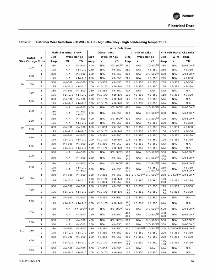
Electrical Data
Table 30. Customer Wire Selection - RTWD - 60 Hz - high efficiency - high condensing temperature
SizeRated
Voltage#
Conn
Wire Selection
Main Terminal Block Disconnect Circuit Breaker Hi-Fault Panel Ckt Brkr
Size Wire Range Size Wire Range Size Wire Range Size Wire Range
Amp XL YD Amp XL YD Amp XL YD Amp XL YD
80
2001 380 N/A #4-500 400 N/A 3/0-500(a) 350 N/A 3/0-500(a) 350 N/A 3/0-500(a)
2 175 N/A #14-2/0 250 N/A #6-350 250 N/A #6-350 250 N/A #6-350
2301 380 N/A #4-500 250 N/A #6-350 300 N/A 3/0-500(a) 300 N/A 3/0-500(a)
2 175 N/A #14-2/0 250 N/A #6-350 225 N/A #6-350 225 N/A #6-350
3801 380 #4-500 #4-500 250 #6-350 #6-350 200 #6-350 #6-350 200 #6-350 #6-350
2 175 #14-2/0 #14-2/0 100 #10-1/0 #10-1/0 125 #6-350 #6-350 125 #6-350 #6-350
4601 380 #4-500 #4-500 250 #6-350 #6-350 N/A N/A N/A N/A N/A N/A
2 175 #14-2/0 #14-2/0 100 #10-1/0 #10-1/0 110 #6-350 #6-350 110 #6-350 #6-350
5751 380 #4-500 #4-500 100 #10-1/0 #10-1/0 125 #6-350 #6-350 N/A N/A N/A
2 175 #14-2/0 #14-2/0 100 #10-1/0 #10-1/0 90 #6-350 #6-350 N/A N/A N/A
90
2001 380 N/A #4-500 400 N/A 3/0-500(a) 450 N/A 3/0-500(a) 450 N/A 3/0-500(a)
2380175
N/A#4-500#14-2/0
250 N/A #6-350 300 N/A 3/0-500(a) 300 N/A 3/0-500(a)
2301 380 N/A #4-500 400 N/A 3/0-500(a) 400 N/A 3/0-500(a) 400 N/A 3/0-500(a)
2 175 N/A #14-2/0 250 N/A #6-350 250 N/A #6-350 250 N/A #6-350
3801 380 #4-500 #4-500 250 #6-350 #6-350 225 #6-350 #6-350 225 #6-350 #6-350
2 175 #14-2/0 #14-2/0 100 #10-1/0 #10-1/0 150 #6-350 #6-350 150 #6-350 #6-350
4601 380 #4-500 #4-500 250 #6-350 #6-350 200 #6-350 #6-350 200 #6-350 #6-350
2 175 #14-2/0 #14-2/0 100 #10-1/0 #10-1/0 125 #6-350 #6-350 125 #6-350 #6-350
5751 380 #4-500 #4-500 250 #6-350 #6-350 150 #6-350 #6-350 N/A N/A N/A
2 175 #14-2/0 #14-2/0 100 #10-1/0 #10-1/0 110 #6-350 #6-350 N/A N/A N/A
100
2001 380 N/A #4-500 400 N/A 3/0-500(a) 500 N/A 3/0-500(a) 500 N/A 3/0-500(a)
2 380 N/A #4-500 250 N/A #6-350300350
N/A 3/0-500(a) 300350
N/A 3/0-500(a)
2301 380 N/A #4-500 400 N/A 3/0-500(a) 450 N/A 3/0-500(a) 450 N/A 3/0-500(a)
2175380
N/A#14-2/0#4-500
250 N/A #6-350250300
N/A#6-350
3/0-500(a)250300
N/A#6-350
3/0-500(a)
3801 380 #4-500 #4-500 250 #6-350 #6-350 250 3/0-500(a) 3/0-500(a) 250 3/0-500(a) 3/0-500(a)
2 175 #14-2/0 #14-2/0100250
#10-1/0#6-350
#10-1/0#6-350
150200
#6-350 #6-350150200
#6-350 #6-350
4601 380 #4-500 #4-500 250 #6-350 #6-350 225 #6-350 #6-350 225 #6-350 #6-350
2 175 #14-2/0 #14-2/0 100 #10-1/0 #10-1/0125150
#6-350 #6-350125150
#6-350 #6-350
5751 380 #4-500 #4-500 250 #6-350 #6-350 175 #6-350 #6-350 N/A N/A N/A
2 175 #14-2/0 #14-2/0 100 #10-1/0 #10-1/0110125
#6-350 #6-350 N/A N/A N/A
110
2001 760 N/A #4-500(a) 600 N/A 3/0-500(a) 500 N/A 3/0-500(a) 500 N/A 3/0-500(a)
2 380 N/A #4-500 250 N/A #6-350400350
N/A 3/0-500(a) 400350
N/A 3/0-500(a)
2301 380 N/A #4-500 400 N/A 3/0-500(a) 500 N/A 3/0-500(a) 500 N/A 3/0-500(a)
2 380 N/A #4-500 250 N/A #6-350 300 N/A 3/0-500(a) 300 N/A 3/0-500(a)
3801 380 #4-500 #4-500 250 #6-350 #6-350 300 3/0-500(a) 3/0-500(a) 300 3/0-500(a) 3/0-500(a)
2 175 #14-2/0 #14-2/0 250 #6-350 #6-350 200 #6-350 #6-350 200 #6-350 #6-350
4601 380 #4-500 #4-500 250 #6-350 #6-350 250 #6-350 #6-350 250 #6-350 #6-350
2 175 #14-2/0 #14-2/0 100 #10-1/0 #10-1/0175150
#6-350 #6-350175150
#6-350 #6-350
5751 380 #4-500 #4-500 250 #6-350 #6-350 N/A N/A N/A N/A N/A N/A
2 175 #14-2/0 #14-2/0 100 #10-1/0 #10-1/0 125 #6-350 #6-350 N/A N/A N/A
RLC-PRC029-EN 57

Electrical Data
120
200
1 760 N/A #4-500(a) 600 N/A 3/0-500(a) 600 N/A 3/0-500(a) 600 N/A 3/0-500(a)
2 380 N/A #4-500 250 N/A #6-350400450
N/A 3/0-500(a) 400450
N/A 3/0-500(a)
2301 760 N/A #4-500(a) 600 N/A 3/0-500(a) 500 N/A 3/0-500(a) 500 N/A 3/0-500(a)
2 380 N/A #4-500 250 N/A #6-350300400
N/A 3/0-500(a) 300400
N/A 3/0-500(a)
3801 380 #4-500 #4-500 250 #6-350 #6-350 300 3/0-500(a) 3/0-500(a) 300 3/0-500(a) 3/0-500(a)
2 175 #14-2/0 #14-2/0 250 #6-350 #6-350200225
#6-350 #6-350200225
#6-350 #6-350
4601 380 #4-500 #4-500 250 #6-350 #6-350 250 3/0-500(a) 3/0-500(a) 250 3/0-500(a) 3/0-500(a)
2 175 #14-2/0 #14-2/0100250
#10-1/0#6-350
#10-1/0#6-350
175200
#6-350 #6-350175200
#6-350 #6-350
5751 380 #4-500 #4-500 250 #6-350 #6-350 200 3/0-500(a) 3/0-500(a) N/A N/A N/A
2 175 #14-2/0 #14-2/0 100 #10-1/0 #10-1/0125150
#6-350 #6-350 N/A N/A N/A
130
2001 N/A N/A N/A N/A N/A N/A N/A N/A N/A N/A N/A N/A
2 380 N/A #4-500 250 N/A #6-350 450 N/A 3/0-500(a) 450 N/A 3/0-500(a)
2301 760 N/A #4-500(a) 600 N/A 3/0-500(a) 500 N/A 3/0-500(a) 500 N/A 3/0-500(a)
2 380 N/A #4-500 250 N/A #6-350 400 N/A 3/0-500(a) 400 N/A 3/0-500(a)
3801 380 #4-500 #4-500 400 3/0-500(a) 3/0-500(a) 350 3/0-500(a) 3/0-500(a) 350 3/0-500(a) 3/0-500(a)
2 175 #14-2/0 #14-2/0 250 #6-350 #6-350 225 #6-350 #6-350 225 #6-350 #6-350
4601 380 #4-500 #4-500 250 #6-350 #6-350 250 3/0-500(a) 3/0-500(a) 250 3/0-500(a) 3/0-500(a)
2 175 #14-2/0 #14-2/0 250 #6-350 #6-350 200 #6-350 #6-350 200 #6-350 #6-350
5751 380 #4-500 #4-500 250 #6-350 #6-350 225 #6-350 #6-350 N/A N/A N/A
2 175 #14-2/0 #14-2/0 100 #10-1/0 #10-1/0 150 #6-350 #6-350 N/A N/A N/A
150
2001 760 N/A #4-500(a) 600 N/A 3/0-500(a) 700 N/A #1-500(b) 700 N/A #1-500(b)
2 380 N/A #4-500250400
N/A#6-350
3/0-500(a)450500
N/A 3/0-500(a) 450500
N/A 3/0-500(a)
2301 760 N/A #4-500(a) 600 N/A 3/0-500(a) 600 N/A 3/0-500(a) 600 N/A 3/0-500(a)
2 380 N/A #4-500250400
N/A#6-350
3/0-500(a)400450
N/A 3/0-500(a) 400450
N/A 3/0-500(a)
3801 380 #4-500 #4-500 400 3/0-500(a) 3/0-500(a) 350 3/0-500(a) 3/0-500(a) 350 3/0-500(a) 3/0-500(a)
2XL 175/380
YD 175#14-2/0#4-500
#14-2/0 250 #6-350 #6-350225250
#6-350 #6-350225250
#6-350 #6-350
4601 380 #4-500 #4-500 250 #6-350 #6-350 300 3/0-500(a) 3/0-500(a) 300 3/0-500(a) 3/0-500(a)
2 175 #14-2/0 #14-2/0 250 #6-350 #6-350200225
#6-350 #6-350200225
#6-350 #6-350
5751 380 #4-500 #4-500 250 #6-350 #6-350 200 #6-350 #6-350 N/A N/A N/A
2 175 #14-2/0 #14-2/0100250
#10-1/0#6-350
#10-1/0#6-350
150175
#6-350 #6-350 N/A N/A N/A
Table 30. Customer Wire Selection - RTWD - 60 Hz - high efficiency - high condensing temperature (continued)
SizeRated
Voltage#
Conn
Wire Selection
Main Terminal Block Disconnect Circuit Breaker Hi-Fault Panel Ckt Brkr
Size Wire Range Size Wire Range Size Wire Range Size Wire Range
Amp XL YD Amp XL YD Amp XL YD Amp XL YD
58 RLC-PRC029-EN
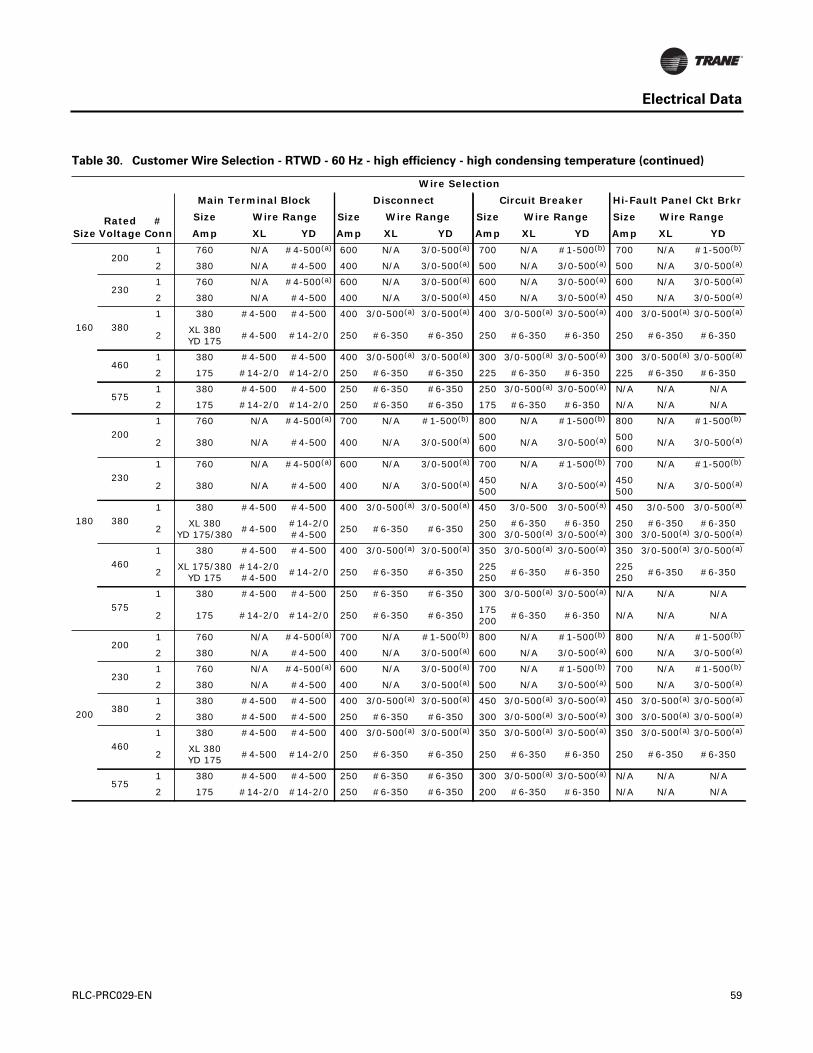
Electrical Data
160
2001 760 N/A #4-500(a) 600 N/A 3/0-500(a) 700 N/A #1-500(b) 700 N/A #1-500(b)
2 380 N/A #4-500 400 N/A 3/0-500(a) 500 N/A 3/0-500(a) 500 N/A 3/0-500(a)
2301 760 N/A #4-500(a) 600 N/A 3/0-500(a) 600 N/A 3/0-500(a) 600 N/A 3/0-500(a)
2 380 N/A #4-500 400 N/A 3/0-500(a) 450 N/A 3/0-500(a) 450 N/A 3/0-500(a)
3801 380 #4-500 #4-500 400 3/0-500(a) 3/0-500(a) 400 3/0-500(a) 3/0-500(a) 400 3/0-500(a) 3/0-500(a)
2XL 380YD 175
#4-500 #14-2/0 250 #6-350 #6-350 250 #6-350 #6-350 250 #6-350 #6-350
4601 380 #4-500 #4-500 400 3/0-500(a) 3/0-500(a) 300 3/0-500(a) 3/0-500(a) 300 3/0-500(a) 3/0-500(a)
2 175 #14-2/0 #14-2/0 250 #6-350 #6-350 225 #6-350 #6-350 225 #6-350 #6-350
5751 380 #4-500 #4-500 250 #6-350 #6-350 250 3/0-500(a) 3/0-500(a) N/A N/A N/A
2 175 #14-2/0 #14-2/0 250 #6-350 #6-350 175 #6-350 #6-350 N/A N/A N/A
180
2001 760 N/A #4-500(a) 700 N/A #1-500(b) 800 N/A #1-500(b) 800 N/A #1-500(b)
2 380 N/A #4-500 400 N/A 3/0-500(a) 500600
N/A 3/0-500(a) 500600
N/A 3/0-500(a)
2301 760 N/A #4-500(a) 600 N/A 3/0-500(a) 700 N/A #1-500(b) 700 N/A #1-500(b)
2 380 N/A #4-500 400 N/A 3/0-500(a) 450500
N/A 3/0-500(a) 450500
N/A 3/0-500(a)
3801 380 #4-500 #4-500 400 3/0-500(a) 3/0-500(a) 450 3/0-500 3/0-500(a) 450 3/0-500 3/0-500(a)
2XL 380
YD 175/380#4-500
#14-2/0#4-500
250 #6-350 #6-350250300
#6-3503/0-500(a)
#6-3503/0-500(a)
250300
#6-3503/0-500(a)
#6-3503/0-500(a)
4601 380 #4-500 #4-500 400 3/0-500(a) 3/0-500(a) 350 3/0-500(a) 3/0-500(a) 350 3/0-500(a) 3/0-500(a)
2XL 175/380
YD 175#14-2/0#4-500
#14-2/0 250 #6-350 #6-350225250
#6-350 #6-350225250
#6-350 #6-350
5751 380 #4-500 #4-500 250 #6-350 #6-350 300 3/0-500(a) 3/0-500(a) N/A N/A N/A
2 175 #14-2/0 #14-2/0 250 #6-350 #6-350175200
#6-350 #6-350 N/A N/A N/A
200
2001 760 N/A #4-500(a) 700 N/A #1-500(b) 800 N/A #1-500(b) 800 N/A #1-500(b)
2 380 N/A #4-500 400 N/A 3/0-500(a) 600 N/A 3/0-500(a) 600 N/A 3/0-500(a)
2301 760 N/A #4-500(a) 600 N/A 3/0-500(a) 700 N/A #1-500(b) 700 N/A #1-500(b)
2 380 N/A #4-500 400 N/A 3/0-500(a) 500 N/A 3/0-500(a) 500 N/A 3/0-500(a)
3801 380 #4-500 #4-500 400 3/0-500(a) 3/0-500(a) 450 3/0-500(a) 3/0-500(a) 450 3/0-500(a) 3/0-500(a)
2 380 #4-500 #4-500 250 #6-350 #6-350 300 3/0-500(a) 3/0-500(a) 300 3/0-500(a) 3/0-500(a)
4601 380 #4-500 #4-500 400 3/0-500(a) 3/0-500(a) 350 3/0-500(a) 3/0-500(a) 350 3/0-500(a) 3/0-500(a)
2XL 380YD 175
#4-500 #14-2/0 250 #6-350 #6-350 250 #6-350 #6-350 250 #6-350 #6-350
5751 380 #4-500 #4-500 250 #6-350 #6-350 300 3/0-500(a) 3/0-500(a) N/A N/A N/A
2 175 #14-2/0 #14-2/0 250 #6-350 #6-350 200 #6-350 #6-350 N/A N/A N/A
Table 30. Customer Wire Selection - RTWD - 60 Hz - high efficiency - high condensing temperature (continued)
SizeRated
Voltage#
Conn
Wire Selection
Main Terminal Block Disconnect Circuit Breaker Hi-Fault Panel Ckt Brkr
Size Wire Range Size Wire Range Size Wire Range Size Wire Range
Amp XL YD Amp XL YD Amp XL YD Amp XL YD
RLC-PRC029-EN 59

Electrical Data
220
2001 760 N/A #4-500(a) 800 N/A #1-500(b) 1000 N/A 250-500(c) 1000 N/A
250-500(c)
2380760
N/A#4-500
#4-500(a)400600
N/A 3/0-500(a) 600700
N/A3/0-500(a)
#1-500(b)600700
N/A3/0-500(a)
#1-500(b)
2301 760 N/A #4-500(a) 700 N/A #1-500(b) 800 N/A #1-500(b) 800 N/A #1-500(b)
2 380 N/A #4-500 400 N/A 3/0-500(a) 500600
N/A 3/0-500(a) 500600
N/A 3/0-500(a)
3801 380 #4-500 #4-500 400 3/0-500(a) 3/0-500(a) 500 3/0-500(a) 3/0-500(a) 500 3/0-500(a) 3/0-500(a)
2 380 #4-500 #4-500 250 #6-350 #6-350300400
3/0-500(a) 3/0-500(a) 300400
3/0-500(a) 3/0-500(a)
4601 380 #4-500 #4-500 400 3/0-500(a) 3/0-
(2)500(a) 400 3/0-500(a) 3/0-500(a) 400 3/0-500(a) 3/0-500(a)
2XL 380
YD175/380#4-500
#14-2/0#4-500
250 #6-350 #6-350250300
#6-3503/0-500(a)
#6-3503/0-500(a)
250300
#6-3503/0-500(a)
#6-3503/0-500(a)
5751 380 #4-500 #4-500 400 3/0-500(a) 3/0-500(a) 350 3/0-500(a) 3/0-500(a) N/A N/A N/A
2XL 175/380
YD 175#14-2/0#4-500
#14-2/0 250 #6-350 #6-350200250
#6-350 #6-350 N/A N/A N/A
250
2001 760 N/A #4-500(a) 800 N/A #1-500(b) 1000 N/A 250-500(c) 1000 N/A
250-500(c)
2 760 N/A #4-500(a) 600 N/A 3/0-500(a) 700 N/A #1-500(b) 700 N/A #1-500(b)
2301 760 N/A #4-500(a) 800 N/A #1-500(b) 800 N/A #1-500(b) 800 N/A #1-500(b)
2 380 N/A #4-500 400 N/A 3/0-500(a) 600 N/A 3/0-500(a) 600 N/A 3/0-500(a)
3801 760
#4-500(a) #4-500(a) 600 3/0-500(a) 3/0-500(a) 500 3/0-500(a) 3/0-500(a) 500 3/0-500(a) 3/0-500(a)
2 380 #4-500 #4-500 250 #6-350 #6-350 400 3/0-500(a) 3/0-500(a) 400 3/0-500(a) 3/0-500(a)
4601 380 #4-500 #4-500 400 3/0-500(a) 3/0-500(a) 450 3/0-500(a) 3/0-500(a) 450 3/0-500(a) 3/0-500(a)
2 380 #4-500 #4-500 250 #6-350 #6-350 300 3/0-500(a) 3/0-500(a) 300 3/0-500(a) 3/0-500(a)
5751 380 #4-500 #4-500 400 3/0-500(a) 3/0-500(a) 350 3/0-500(a) 3/0-500(a) N/A N/A N/A
2XL 380YD 175
#4-500 #14-2/0 250 #6-350 #6-350 250 #6-350 #6-350 N/A N/A N/A
Notes:
1. Optional non-fused disconnect and circuit breaker. 2. Copper wire only, based on nameplate minimum circuit ampacity (MCA). 3. Standard condensing temperature option refers to entering condenser water temperatures 95°F (35°C) and below. 4. Circuit two information is the same as circuit one unless listed on a separate line below circuit one values. 5. XL - across-the-line starter and YD - wye-delta starter.
(a) Will accept 2 conduits per phase in this size.(b) Will accept 3 conduits per phase in this size.(c) Will accept 4 conduits per phase in this size.
Table 30. Customer Wire Selection - RTWD - 60 Hz - high efficiency - high condensing temperature (continued)
SizeRated
Voltage#
Conn
Wire Selection
Main Terminal Block Disconnect Circuit Breaker Hi-Fault Panel Ckt Brkr
Size Wire Range Size Wire Range Size Wire Range Size Wire Range
Amp XL YD Amp XL YD Amp XL YD Amp XL YD
60 RLC-PRC029-EN

Electrical Data
Table 31. Customer Wire Selection - RTWD - 60 Hz - premium efficiency - high condensing temperature
SizeRated
Voltage#
Conn
Wire Selection
Main Terminal Block Disconnect Circuit Breaker Hi-Fault Panel Ckt Brkr
Size Wire Range Size Wire Range Size Wire Range Size Wire Range
Amp XL YD Amp XL YD Amp XL YD Amp XL YD
150
2001 760 N/A #4-500(a) 600 N/A 3/0-500(a) 700 N/A #1-500(b) 700 N/A #1-500(c)
2 380 N/A #4-500250400
N/A#6-350
3/0-500(a)400500
N/A 3/0-500(a) 400500
N/A 3/0-500(a)
2301 760 N/A #4-500(a) 600 N/A 3/0-500(a) 600 N/A 3/0-500(a) 600 N/A 3/0-500(a)
2 380 N/A #4-500250400
N/A#6-350
3/0-500(a)350450
N/A 3/0-500(a) 350450
N/A 3/0-500(a)
3801 380 #4-500 #4-500 400 3/0-500(a) 3/0-500(a) 350 3/0-500 3/0-500(a) 350 3/0-500 3/0-500(a)
2XL 175/380
YD 175#14-2/0#4-500
#14-2/0 250 #6-350 #6-350225250
#6-350 #6-350225250
#6-350 #6-350
4601 380 #4-500 #4-500 250 #6-350 #6-350 300 3/0-500(a) 3/0-500(a) 300 3/0-500(a) 3/0-500(a)
2 175 #14-2/0 #14-2/0 250 #6-350 #6-350175225
#6-350 #6-350175225
#6-350 #6-350
5751 380 #4-500 #4-500 250 #6-350 #6-350 250 #6-350 #6-350 N/A N/A N/A
2 175 #14-2/0 #14-2/0100250
#10-1/0#6-350
#10-1/0#6-350
150175
#6-350 #6-350 N/A N/A N/A
160
2001 760 N/A #4-500(a) 600 N/A 3/0-500(a) 700 N/A #1-500(b) 700 N/A #1-500(b)
2 380 N/A #4-500 400 N/A 3/0-500(a) 500 N/A 3/0-500(a) 500 N/A 3/0-500(a)
2301 760 N/A #4-500(a) 600 N/A 3/0-500(a) 600 N/A 3/0-500(a) 600 N/A 3/0-500(a)
2 380 N/A #4-500 400 N/A 3/0-500(a) 450 N/A 3/0-500(a) 450 N/A 3/0-500(a)
3801 380 #4-500 #4-500 400 3/0-500(a) 3/0-500(a) 400 3/0-500(a) 3/0-500(a) 400 3/0-500(a) 3/0-500(a)
2XL 380YD 175
#4-500 #14-2/0 250 #6-350 #6-350 250 #6-350 #6-350 250 #6-350 #6-350
4601 380 #4-500 #4-500 400 3/0-500(a) 3/0-500(a) 300 3/0-500(a) 3/0-500(a) 300 3/0-500(a) 3/0-500(a)
2 175 #14-2/0 #14-2/0 250 #6-350 #6-350 225 #6-350 #6-350 225 #6-350 #6-350
5751 380 #4-500 #4-500 250 #6-350 #6-350 250 3/0-500(a) 3/0-500(a) N/A N/A N/A
2 175 #14-2/0 #14-2/0 250 #6-350 #6-350 175 #6-350 #6-350 N/A N/A N/A
180
2001 760 N/A #4-500(a) 700 N/A #1-500(b) 800 N/A #1-500(b) 800 N/A #1-500(b)
2 380 N/A #4-500 400 N/A 3/0-500(a) 500600
N/A 3/0-500(a) 500600
N/A 3/0-500(a)
2301 760 N/A #4-500(a) 600 N/A 3/0-500(a) 700 N/A #1-500(b) 700 N/A #1-500(b)
2 380 N/A #4-500 400 N/A 3/0-500(a) 450500
N/A 3/0-500(a) 450500
N/A 3/0-500(a)
3801 380 #4-500 #4-500 400 3/0-500(a) 3/0-500(a) 450 3/0-500 3/0-500(a) 450 3/0-500 3/0-500(a)
2XL 380
YD 175/380#4-500
#14-2/0#4-500
250 #6-350 #6-350250300
#6-3503/0-500(a)
#6-3503/0-500(a)
250300
#6-3503/0-500(a)
#6-3503/0-500(a)
460
1 380 #4-500 #4-500 400 3/0-500(a) 3/0-500(a) 350 3/0-500(a) 3/0-500(a) 350 3/0-500(a) 3/0-500(a)
2XL 175/380
YD 175#14-2/0#4-500
#14-2/0 250 #6-350 #6-350225250
#6-350 #6-350225250
#6-350 #6-350
5751 380 #4-500 #4-500 250 #6-350 #6-350 300 3/0-500(a) 3/0-500(a) N/A N/A N/A
2 175 #14-2/0 #14-2/0 250 #6-350 #6-350175200
#6-350 #6-350 N/A N/A N/A
RLC-PRC029-EN 61
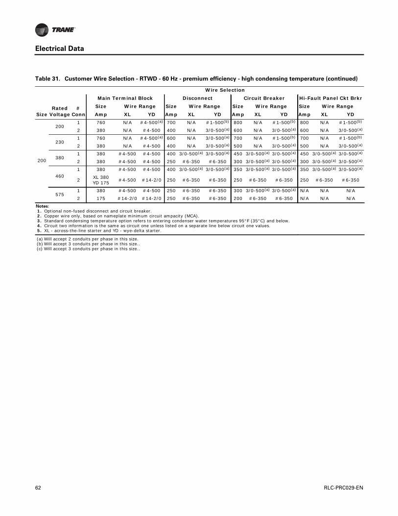
Electrical Data
200
2001 760 N/A #4-500(a) 700 N/A #1-500(b) 800 N/A #1-500(b) 800 N/A #1-500(b)
2 380 N/A #4-500 400 N/A 3/0-500(a) 600 N/A 3/0-500(a) 600 N/A 3/0-500(a)
2301 760 N/A #4-500(a) 600 N/A 3/0-500(a) 700 N/A #1-500(b) 700 N/A #1-500(b)
2 380 N/A #4-500 400 N/A 3/0-500(a) 500 N/A 3/0-500(a) 500 N/A 3/0-500(a)
3801 380 #4-500 #4-500 400 3/0-500(a) 3/0-500(a) 450 3/0-500(a) 3/0-500(a) 450 3/0-500(a) 3/0-500(a)
2 380 #4-500 #4-500 250 #6-350 #6-350 300 3/0-500(a) 3/0-500(a) 300 3/0-500(a) 3/0-500(a)
4601 380 #4-500 #4-500 400 3/0-500(a) 3/0-500(a) 350 3/0-500(a) 3/0-500(a) 350 3/0-500(a) 3/0-500(a)
2XL 380YD 175
#4-500 #14-2/0 250 #6-350 #6-350 250 #6-350 #6-350 250 #6-350 #6-350
5751 380 #4-500 #4-500 250 #6-350 #6-350 300 3/0-500(a) 3/0-500(a) N/A N/A N/A
2 175 #14-2/0 #14-2/0 250 #6-350 #6-350 200 #6-350 #6-350 N/A N/A N/A
Notes:
1. Optional non-fused disconnect and circuit breaker. 2. Copper wire only, based on nameplate minimum circuit ampacity (MCA). 3. Standard condensing temperature option refers to entering condenser water temperatures 95°F (35°C) and below. 4. Circuit two information is the same as circuit one unless listed on a separate line below circuit one values. 5. XL - across-the-line starter and YD - wye-delta starter.
(a) Will accept 2 conduits per phase in this size.(b) Will accept 3 conduits per phase in this size..(c) Will accept 3 conduits per phase in this size..
Table 31. Customer Wire Selection - RTWD - 60 Hz - premium efficiency - high condensing temperature (continued)
SizeRated
Voltage#
Conn
Wire Selection
Main Terminal Block Disconnect Circuit Breaker Hi-Fault Panel Ckt Brkr
Size Wire Range Size Wire Range Size Wire Range Size Wire Range
Amp XL YD Amp XL YD Amp XL YD Amp XL YD
62 RLC-PRC029-EN

Electrical Data
Table 32. Customer Wire Selection - RTUD - 60 Hz
SizeRated
Voltage#
Conn
Wire Selection
Main Terminal Block Disconnect Circuit Breaker Hi-Fault Panel Ckt Brkr
Size Wire Range Size Wire Range Size Wire Range Size Wire Range
Amp XL YD Amp XL YD Amp XL YD Amp XL YD
80
2001 380 N/A #4-500 400 N/A 3/0-500(a) 400 N/A 3/0-500(a) 400 N/A 3/0-500(a)
2 175 N/A #14-2/0 250 N/A #6-350 250 N/A #6-350 250 N/A #6-350
2301 380 N/A #4-500 400 N/A 3/0-500(a) 350 N/A 3/0-500(a) 350 N/A 3/0-500(a)
2 175 N/A #14-2/0 250 N/A #6-350 250 N/A #6-350 250 N/A #6-350
3801 175 #14-2/0 #14-2/0 250 #6-350 #6-350 225 #6-350 #6-350 225 #6-350 #6-350
2 175 #14-2/0 #14-2/0 100 #10-1/0 #10-1/0 150 #6-350 #6-350 150 #6-350 #6-350
4601 175 #14-2/0 #14-2/0 250 #6-350 #6-350 175 #6-350 #6-350 175 #6-350 #6-350
2 175 #14-2/0 #14-2/0 100 #10-1/0 #10-1/0 125 #6-350 #6-350 125 #6-350 #6-350
5751 175 #14-2/0 #14-2/0 250 #6-350 #6-350 150 #6-350 #6-350 N/A N/A N/A
2 175 #14-2/0 #14-2/0 100 #10-1/0 #10-1/0 100 #6-350 #6-350 N/A N/A N/A
90
200
1 380 N/A #4-500 400 N/A 3/0-500(a) 500 N/A 3/0-500(a) 500 N/A 3/0-500(a)
2 380 N/A #4-500 250 N/A #6-350350/300
N/A 3/0-500(a) 350/300
N/A 3/0-500(a)
2301 380 N/A #4-500 400 N/A 3/0-500(a) 400 N/A 3/0-500(a) 400 N/A 3/0-500(a)
2 175 N/A #14-2/0 250 N/A #6-350 250 N/A #6-350 250 N/A #6-350
3801 380 #4-500 #4-500 250 #6-350 #6-350 250 3/0-500(a) 3/0-500(a) 250 3/0-500(a) 3/0-500(a)
2 175 #14-2/0 #14-2/0 250 #6-350 #6-350 175 #6-350 #6-350 175 #6-350 #6-350
4601 175 #14-2/0 #14-2/0 250 #6-350 #6-350 200 #6-350 #6-350 200 #6-350 #6-350
2 175 #14-2/0 #14-2/0 100 #10-1/0 #10-1/0 150 #6-350 #6-350 150 #6-350 #6-350
5751 175 #14-2/0 #14-2/0 250 #6-350 #6-350 175 #6-350 #6-350 N/A N/A N/A
2 175 #14-2/0 #14-2/0 100 #10-1/0 #10-1/0 110 #6-350 #6-350 N/A N/A N/A
100
200
1 760 N/A #4-500(a) 600 N/A 3/0-500(a) 500 N/A 3/0-500(a) 500 N/A 3/0-500(a)
2 380 N/A #4-500 250 N/A #6-350350/400
N/A 3/0-500(a) 350/400
N/A 3/0-500(a)
230
1 380 N/A #4-500 400 N/A 3/0-500(a) 500 N/A 3/0-500(a) 500 N/A 3/0-500(a)
2175/380
N/A#14-2/0#4-500
250 N/A #6-350250/350
N/A#6-350
3/0-500(a)250/350
N/A#6-350
3/0-500(a)
380
1 380 #4-500 #4-500 250 #6-350 #6-350 300 3/0-500(a) 3/0-500(a) 300 3/0-500(a) 3/0-500(a)
2 175 #14-2/0 #14-2/0 250 #6-350 #6-350175/225
#6-350 #6-350175/225
#6-350 #6-350
460
1 175 #14-2/0 #14-2/0 250 #6-350 #6-350 250 #6-350 #6-350 250 #6-350 #6-350
2 175 #14-2/0 #14-2/0100/250
#10-1/0#6-350
#10-1/0#6-350
150/175
#6-350 #6-350150/175
#6-350 #6-350
575
1 175 #14-2/0 #14-2/0 250 #6-350 #6-350 200 #6-350 #6-350 N/A N/A N/A
2 175 #14-2/0 #14-2/0 100 #10-1/0 #10-1/0110/150
#6-350 #6-350 N/A N/A N/A
RLC-PRC029-EN 63

Electrical Data
110
200
1 760 N/A#4-
(2)500(a) 600 N/A3/0-
(2)500(a) 600 N/A3/0-
(2)500(a) 600 N/A3/0-
(2)500(a)
2 380 N/A #4-500 250 N/A #6-350 400 N/A3/0-
(2)500(a) 400 N/A3/0-
(2)500(a)
230
1 380 N/A #4-500 600 N/A3/0-
(2)500(a) 500 N/A3/0-
(2)500(a) 500 N/A3/0-
(2)500(a)
2 380 N/A #4-500 250 N/A #6-350 350 N/A3/0-
(2)500(a) 350 N/A3/0-
(2)500(a)
3801 380 #4-500 #4-500 400 3/0-(2)500
3/0-(2)500(a) 300
3/0-(2)500
3/0-(2)500(a) 300
3/0-(2)500
3/0-(2)500(a)
2 175 #14-2/0 #14-2/0 250 #6-350 #6-350 225 #6-350 #6-350 225 #6-350 #6-350
4601 380 #4-500 #4-500 250 #6-350 #6-350 250
3/0-(2)500
3/0-(2)500(a) 250
3/0-(2)500
3/0-(2)500(a)
2 175 #14-2/0 #14-2/0 250 #6-350 #6-350 175 #6-350 #6-350 175 #6-350 #6-350
5751 175 #14-2/0 #14-2/0 250 #6-350 #6-350 200 #6-350 #6-350 N/A N/A N/A
2 175 #14-2/0 #14-2/0 100 #10-1/0 #10-1/0 150 #6-350 #6-350 N/A N/A N/A
120
200
1 760 N/A#4-
(2)500(a) 600 N/A3/0-
(2)500(a) 600 N/A3/0-
(2)500(a) 600 N/A3/0-
(2)500(a)
2 380 N/A #4-500250/400
N/A#6-350
3/0-(2)500(a)
400/450
N/A3/0-
(2)500(a)400/450
N/A3/0-
(2)500(a)
230
1 760 N/A#4-
(2)500(a) 600 N/A3/0-
(2)500(a) 600 N/A3/0-
(2)500(a) 600 N/A3/0-
(2)500(a)
2 380 N/A #4-500 250 N/A #6-350350/450
N/A3/0-
(2)500(a)350/450
N/A3/0-
(2)500(a)
380
1 380 #4-500 #4-500 400 3/0-(2)5003/0-
(2)500(a) 3503/0-
(2)5003/0-
(2)500(a) 3503/0-
(2)5003/0-
(2)500(a)
2 175 #14-2/0 #14-2/0 250 #6-350 #6-350225/250
#6-350 #6-350225/250
#6-350 #6-350
460
1 380 #4-500 #4-500 250 #6-350 #6-350 3003/0-
(2)500(a)3/0-
(2)500(a) 3003/0-
(2)500(a)3/0-
(2)500(a)
2 175 #14-2/0 #14-2/0 250 #6-350 #6-350175/225
#6-350 #6-350175/225
#6-350 #6-350
575
1 175 #14-2/0 #14-2/0 250 #6-350 #6-350 225 #6-350 #6-350 N/A N/A N/A
2 175 #14-2/0 #14-2/0 100 #10-1/0 #10-1/0150/175
#6-350 #6-350 N/A N/A N/A
Table 32. Customer Wire Selection - RTUD - 60 Hz (continued)
SizeRated
Voltage#
Conn
Wire Selection
Main Terminal Block Disconnect Circuit Breaker Hi-Fault Panel Ckt Brkr
Size Wire Range Size Wire Range Size Wire Range Size Wire Range
Amp XL YD Amp XL YD Amp XL YD Amp XL YD
64 RLC-PRC029-EN

Electrical Data
130
200
1 760 N/A#4-
(2)500(a) 600 N/A3/0-
(2)500(a) 600 N/A3/0-
(2)500(a) 600 N/A3/0-
(2)500(a)
2 380 N/A #4-500 400 N/A3/0-
(2)500(a) 450 N/A3/0-
(2)500(a) 450 N/A3/0-
(2)500(a)
230
1 760 N/A#4-
(2)500(a) 600 N/A3/0-
(2)500(a) 600 N/A3/0-
(2)500(a) 600 N/A3/0-
(2)500(a)
2 380 N/A #4-500 250 N/A #6-350 450 N/A3/0-
(2)500(a) 450 N/A3/0-
(2)500(a)
3801 380 #4-500 #4-500 400
3/0-(2)500(a)
3/0-(2)500(a) 350
3/0-(2)500
3/0-(2)500(a) 350
3/0-(2)500
3/0-(2)500(a)
2 175 #14-2/0 #14-2/0 250 #6-350 #6-350 250 #6-350 #6-350 250 #6-350 #6-350
4601 380 #4-500 #4-500 250 #6-350 #6-350 300
3/0-(2)500(a)
3/0-(2)500(a) 300
3/0-(2)500(a)
3/0-(2)500(a)
2 175 #14-2/0 #14-2/0 250 #6-350 #6-350 225 #6-350 #6-350 225 #6-350 #6-350
5751 380 #4-500 #4-500 250 #6-350 #6-350 250
3/0-(2)500(a)
3/0-(2)500(a) N/A N/A N/A
2 175 #14-2/0 #14-2/0 100 #10-1/0 #10-1/0 175 #6-350 #6-350 N/A N/A N/A
150
200
1 760 N/A #4-500(a) 700 N/A #1-500(b) 800 N/A #1-500(b) 800 N/A #1-500(b)
2 380 N/A #4-500 400 N/A 3/0-500(a) 450/600
N/A 3/0-500(a) 450/600
N/A 3/0-500(a)
230
1 760 N/A #4-500(a) 600 N/A 3/0-500(a) 700 N/A #1-500(b) 700 N/A #1-500(b)
2 380 N/A #4-500250/400
N/A#6-350
3/0-500(a)
700450/500
N/A#1-500(b)
3/0-500(a)
700450/500
N/A#1-500(b)
3/0-500(a)
380
1 380 #4-500 #4-500 400 3/0-500(a) 3/0-500(a) 400 3/0-500(a) 3/0-500(a) 400 3/0-500(a) 3/0-500(a)
2175/380
#14-2/0#4-500
#14-2/0#4-500
250 #6-350 #6-350250/300
#6-3503/0-500(a)
#6-3503/0-500(a)
250/300
#6-3503/0-500(a)
#6-3503/0-500(a)
460
1 380 #4-500 #4-500 400 3/0-500(a) 3/0-500(a) 350 3/0-500(a) 3/0-500(a) 350 3/0-500(a) 3/0-500(a)
2 175 #14-2/0 #14-2/0 250 #6-350 #6-350225/250
#6-350 #6-350225/250
#6-350 #6-350
575
1 380 #4-500 #4-500 250 #6-350 #6-350 250 3/0-500(a) 3/0-500(a) N/A N/A N/A
2 175 #14-2/0 #14-2/0100/250
#10-1/0#6-350
#10-1/0#6-350
175/200
#6-350 #6-350 N/A N/A N/A
160
2001 760 N/A #4-500(a) 700 N/A #1-500(b) 800 N/A #1-500(b) 800 N/A #1-500(b)
2 380 N/A #4-500 400 N/A 3/0-500(a) 600 N/A 3/0-500(a) 600 N/A 3/0-500(a)
2301 760 N/A #4-500(a) 600 N/A 3/0-500(a) 700 N/A #1-500(b) 700 N/A #1-500(b)
2 380 N/A #4-500 400 N/A 3/0-500(a) 500 N/A 3/0-500(a) 500 N/A 3/0-500(a)
3801 380 #4-500 #4-500 400 3/0-500(a) 3/0-500(a) 450 3/0-500(a) 3/0-500(a) 450 3/0-500(a) 3/0-500(a)
2 380 #4-500 #4-500 250 #6-350 #6-350 300 3/0-500(a) 3/0-500(a) 300 3/0-500(a) 3/0-500(a)
4601 380 #4-500 #4-500 400 3/0-500(a) 3/0-500(a) 350 3/0-500(a) 3/0-500(a) 350 3/0-500(a) 3/0-500(a)
2 175 #14-2/0 #14-2/0 250 #6-350 #6-350 250 #6-350 #6-350 250 #6-350 #6-350
5751 380 #4-500 #4-500 250 #6-350 #6-350 300 3/0-500(a) 3/0-500(a) N/A N/A N/A
2 175 #14-2/0 #14-2/0 250 #6-350 #6-350 200 #6-350 #6-350 N/A N/A N/A
Table 32. Customer Wire Selection - RTUD - 60 Hz (continued)
SizeRated
Voltage#
Conn
Wire Selection
Main Terminal Block Disconnect Circuit Breaker Hi-Fault Panel Ckt Brkr
Size Wire Range Size Wire Range Size Wire Range Size Wire Range
Amp XL YD Amp XL YD Amp XL YD Amp XL YD
RLC-PRC029-EN 65
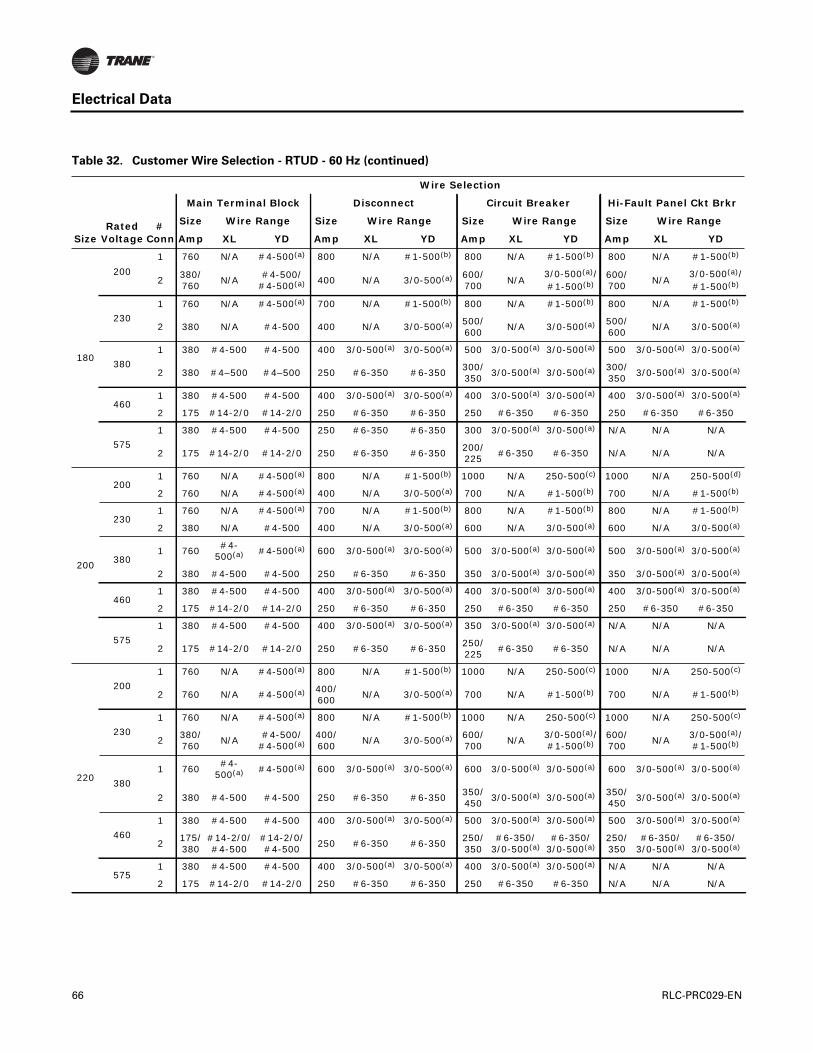
Electrical Data
180
200
1 760 N/A #4-500(a) 800 N/A #1-500(b) 800 N/A #1-500(b) 800 N/A #1-500(b)
2380/760
N/A#4-500/
#4-500(a) 400 N/A 3/0-500(a) 600/700
N/A3/0-500(a)/#1-500(b)
600/700
N/A3/0-500(a)/#1-500(b)
230
1 760 N/A #4-500(a) 700 N/A #1-500(b) 800 N/A #1-500(b) 800 N/A #1-500(b)
2 380 N/A #4-500 400 N/A 3/0-500(a) 500/600
N/A 3/0-500(a) 500/600
N/A 3/0-500(a)
380
1 380 #4-500 #4-500 400 3/0-500(a) 3/0-500(a) 500 3/0-500(a) 3/0-500(a) 500 3/0-500(a) 3/0-500(a)
2 380 #4–500 #4–500 250 #6-350 #6-350300/350
3/0-500(a) 3/0-500(a) 300/350
3/0-500(a) 3/0-500(a)
4601 380 #4-500 #4-500 400 3/0-500(a) 3/0-500(a) 400 3/0-500(a) 3/0-500(a) 400 3/0-500(a) 3/0-500(a)
2 175 #14-2/0 #14-2/0 250 #6-350 #6-350 250 #6-350 #6-350 250 #6-350 #6-350
575
1 380 #4-500 #4-500 250 #6-350 #6-350 300 3/0-500(a) 3/0-500(a) N/A N/A N/A
2 175 #14-2/0 #14-2/0 250 #6-350 #6-350200/225
#6-350 #6-350 N/A N/A N/A
200
2001 760 N/A #4-500(a) 800 N/A #1-500(b) 1000 N/A 250-500(c) 1000 N/A 250-500(d)
2 760 N/A #4-500(a) 400 N/A 3/0-500(a) 700 N/A #1-500(b) 700 N/A #1-500(b)
2301 760 N/A #4-500(a) 700 N/A #1-500(b) 800 N/A #1-500(b) 800 N/A #1-500(b)
2 380 N/A #4-500 400 N/A 3/0-500(a) 600 N/A 3/0-500(a) 600 N/A 3/0-500(a)
3801 760
#4-500(a) #4-500(a) 600 3/0-500(a) 3/0-500(a) 500 3/0-500(a) 3/0-500(a) 500 3/0-500(a) 3/0-500(a)
2 380 #4-500 #4-500 250 #6-350 #6-350 350 3/0-500(a) 3/0-500(a) 350 3/0-500(a) 3/0-500(a)
4601 380 #4-500 #4-500 400 3/0-500(a) 3/0-500(a) 400 3/0-500(a) 3/0-500(a) 400 3/0-500(a) 3/0-500(a)
2 175 #14-2/0 #14-2/0 250 #6-350 #6-350 250 #6-350 #6-350 250 #6-350 #6-350
575
1 380 #4-500 #4-500 400 3/0-500(a) 3/0-500(a) 350 3/0-500(a) 3/0-500(a) N/A N/A N/A
2 175 #14-2/0 #14-2/0 250 #6-350 #6-350250/225
#6-350 #6-350 N/A N/A N/A
220
200
1 760 N/A #4-500(a) 800 N/A #1-500(b) 1000 N/A 250-500(c) 1000 N/A 250-500(c)
2 760 N/A #4-500(a) 400/600
N/A 3/0-500(a) 700 N/A #1-500(b) 700 N/A #1-500(b)
230
1 760 N/A #4-500(a) 800 N/A #1-500(b) 1000 N/A 250-500(c) 1000 N/A 250-500(c)
2380/760
N/A#4-500/
#4-500(a)400/600
N/A 3/0-500(a) 600/700
N/A3/0-500(a)/#1-500(b)
600/700
N/A3/0-500(a)/#1-500(b)
380
1 760#4-
500(a) #4-500(a) 600 3/0-500(a) 3/0-500(a) 600 3/0-500(a) 3/0-500(a) 600 3/0-500(a) 3/0-500(a)
2 380 #4-500 #4-500 250 #6-350 #6-350350/450
3/0-500(a) 3/0-500(a) 350/450
3/0-500(a) 3/0-500(a)
460
1 380 #4-500 #4-500 400 3/0-500(a) 3/0-500(a) 500 3/0-500(a) 3/0-500(a) 500 3/0-500(a) 3/0-500(a)
2175/380
#14-2/0/#4-500
#14-2/0/#4-500
250 #6-350 #6-350250/350
#6-350/3/0-500(a)
#6-350/3/0-500(a)
250/350
#6-350/3/0-500(a)
#6-350/3/0-500(a)
5751 380 #4-500 #4-500 400 3/0-500(a) 3/0-500(a) 400 3/0-500(a) 3/0-500(a) N/A N/A N/A
2 175 #14-2/0 #14-2/0 250 #6-350 #6-350 250 #6-350 #6-350 N/A N/A N/A
Table 32. Customer Wire Selection - RTUD - 60 Hz (continued)
SizeRated
Voltage#
Conn
Wire Selection
Main Terminal Block Disconnect Circuit Breaker Hi-Fault Panel Ckt Brkr
Size Wire Range Size Wire Range Size Wire Range Size Wire Range
Amp XL YD Amp XL YD Amp XL YD Amp XL YD
66 RLC-PRC029-EN
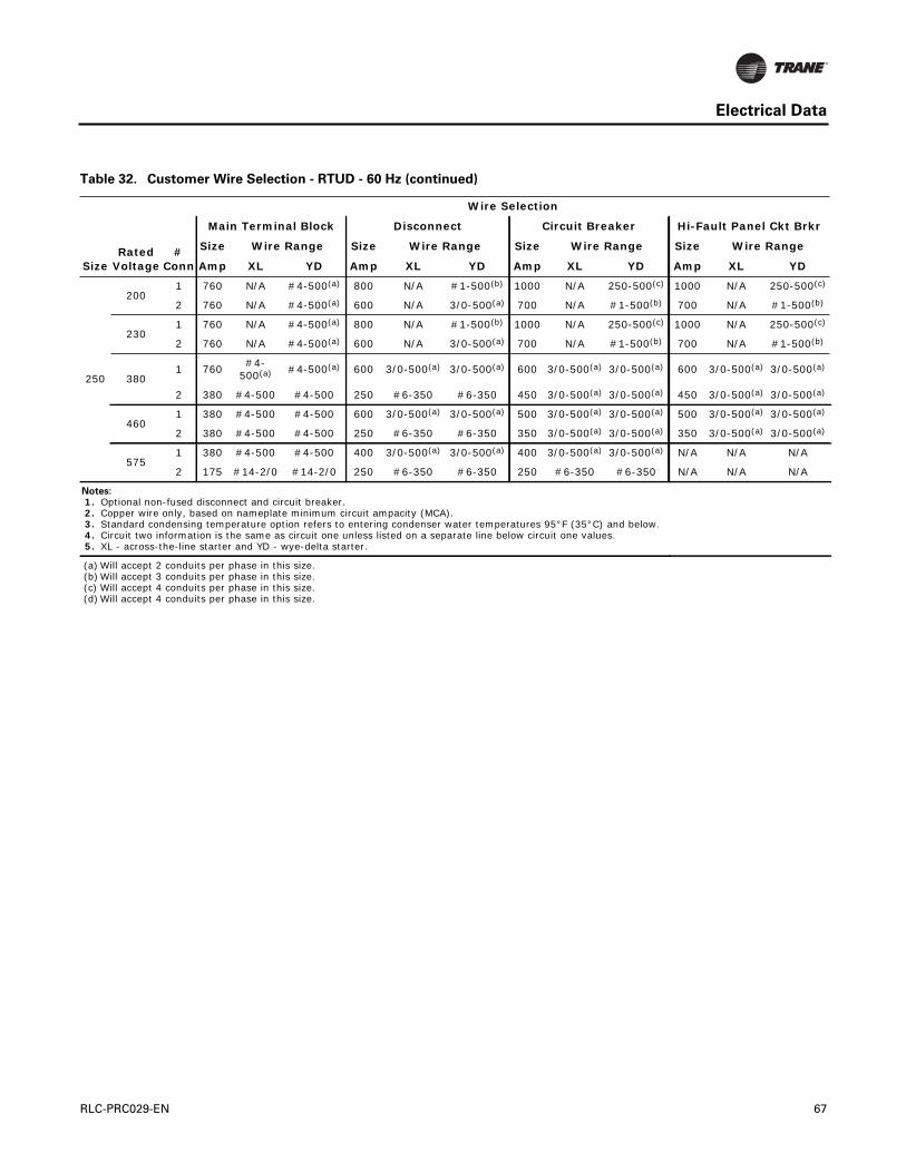
Electrical Data
250
2001 760 N/A #4-500(a) 800 N/A #1-500(b) 1000 N/A 250-500(c) 1000 N/A 250-500(c)
2 760 N/A #4-500(a) 600 N/A 3/0-500(a) 700 N/A #1-500(b) 700 N/A #1-500(b)
2301 760 N/A #4-500(a) 800 N/A #1-500(b) 1000 N/A 250-500(c) 1000 N/A 250-500(c)
2 760 N/A #4-500(a) 600 N/A 3/0-500(a) 700 N/A #1-500(b) 700 N/A #1-500(b)
3801 760
#4-500(a) #4-500(a) 600 3/0-500(a) 3/0-500(a) 600 3/0-500(a) 3/0-500(a) 600 3/0-500(a) 3/0-500(a)
2 380 #4-500 #4-500 250 #6-350 #6-350 450 3/0-500(a) 3/0-500(a) 450 3/0-500(a) 3/0-500(a)
4601 380 #4-500 #4-500 600 3/0-500(a) 3/0-500(a) 500 3/0-500(a) 3/0-500(a) 500 3/0-500(a) 3/0-500(a)
2 380 #4-500 #4-500 250 #6-350 #6-350 350 3/0-500(a) 3/0-500(a) 350 3/0-500(a) 3/0-500(a)
5751 380 #4-500 #4-500 400 3/0-500(a) 3/0-500(a) 400 3/0-500(a) 3/0-500(a) N/A N/A N/A
2 175 #14-2/0 #14-2/0 250 #6-350 #6-350 250 #6-350 #6-350 N/A N/A N/A
Notes:
1. Optional non-fused disconnect and circuit breaker. 2. Copper wire only, based on nameplate minimum circuit ampacity (MCA). 3. Standard condensing temperature option refers to entering condenser water temperatures 95°F (35°C) and below. 4. Circuit two information is the same as circuit one unless listed on a separate line below circuit one values. 5. XL - across-the-line starter and YD - wye-delta starter.
(a) Will accept 2 conduits per phase in this size.(b) Will accept 3 conduits per phase in this size.(c) Will accept 4 conduits per phase in this size.(d) Will accept 4 conduits per phase in this size.
Table 32. Customer Wire Selection - RTUD - 60 Hz (continued)
SizeRated
Voltage#
Conn
Wire Selection
Main Terminal Block Disconnect Circuit Breaker Hi-Fault Panel Ckt Brkr
Size Wire Range Size Wire Range Size Wire Range Size Wire Range
Amp XL YD Amp XL YD Amp XL YD Amp XL YD
RLC-PRC029-EN 67

Electrical Connection
Figure 1. RTWD/RTUD - Field Wiring Diagram
68 RLC-PRC029-EN

Electrical Connection
RLC-PRC029-EN 69
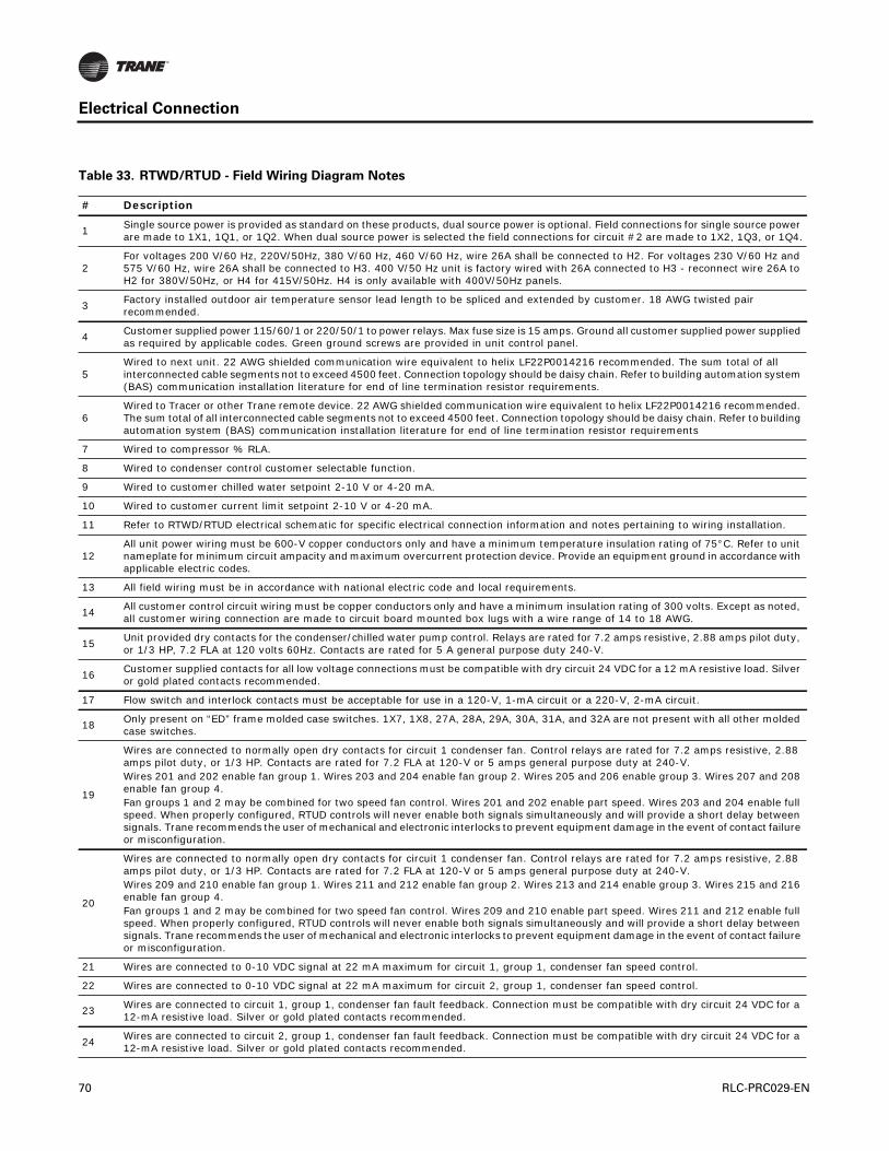
Electrical Connection
Table 33. RTWD/RTUD - Field Wiring Diagram Notes
# Description
1Single source power is provided as standard on these products, dual source power is optional. Field connections for single source power are made to 1X1, 1Q1, or 1Q2. When dual source power is selected the field connections for circuit #2 are made to 1X2, 1Q3, or 1Q4.
2For voltages 200 V/60 Hz, 220V/50Hz, 380 V/60 Hz, 460 V/60 Hz, wire 26A shall be connected to H2. For voltages 230 V/60 Hz and 575 V/60 Hz, wire 26A shall be connected to H3. 400 V/50 Hz unit is factory wired with 26A connected to H3 - reconnect wire 26A to H2 for 380V/50Hz, or H4 for 415V/50Hz. H4 is only available with 400V/50Hz panels.
3Factory installed outdoor air temperature sensor lead length to be spliced and extended by customer. 18 AWG twisted pair recommended.
4Customer supplied power 115/60/1 or 220/50/1 to power relays. Max fuse size is 15 amps. Ground all customer supplied power supplied as required by applicable codes. Green ground screws are provided in unit control panel.
5Wired to next unit. 22 AWG shielded communication wire equivalent to helix LF22P0014216 recommended. The sum total of all interconnected cable segments not to exceed 4500 feet. Connection topology should be daisy chain. Refer to building automation system (BAS) communication installation literature for end of line termination resistor requirements.
6Wired to Tracer or other Trane remote device. 22 AWG shielded communication wire equivalent to helix LF22P0014216 recommended. The sum total of all interconnected cable segments not to exceed 4500 feet. Connection topology should be daisy chain. Refer to building automation system (BAS) communication installation literature for end of line termination resistor requirements
7 Wired to compressor % RLA.
8 Wired to condenser control customer selectable function.
9 Wired to customer chilled water setpoint 2-10 V or 4-20 mA.
10 Wired to customer current limit setpoint 2-10 V or 4-20 mA.
11 Refer to RTWD/RTUD electrical schematic for specific electrical connection information and notes pertaining to wiring installation.
12All unit power wiring must be 600-V copper conductors only and have a minimum temperature insulation rating of 75°C. Refer to unit nameplate for minimum circuit ampacity and maximum overcurrent protection device. Provide an equipment ground in accordance with applicable electric codes.
13 All field wiring must be in accordance with national electric code and local requirements.
14All customer control circuit wiring must be copper conductors only and have a minimum insulation rating of 300 volts. Except as noted, all customer wiring connection are made to circuit board mounted box lugs with a wire range of 14 to 18 AWG.
15Unit provided dry contacts for the condenser/chilled water pump control. Relays are rated for 7.2 amps resistive, 2.88 amps pilot duty, or 1/3 HP, 7.2 FLA at 120 volts 60Hz. Contacts are rated for 5 A general purpose duty 240-V.
16Customer supplied contacts for all low voltage connections must be compatible with dry circuit 24 VDC for a 12 mA resistive load. Silver or gold plated contacts recommended.
17 Flow switch and interlock contacts must be acceptable for use in a 120-V, 1-mA circuit or a 220-V, 2-mA circuit.
18Only present on “ED” frame molded case switches. 1X7, 1X8, 27A, 28A, 29A, 30A, 31A, and 32A are not present with all other molded case switches.
19
Wires are connected to normally open dry contacts for circuit 1 condenser fan. Control relays are rated for 7.2 amps resistive, 2.88 amps pilot duty, or 1/3 HP. Contacts are rated for 7.2 FLA at 120-V or 5 amps general purpose duty at 240-V. Wires 201 and 202 enable fan group 1. Wires 203 and 204 enable fan group 2. Wires 205 and 206 enable group 3. Wires 207 and 208 enable fan group 4.Fan groups 1 and 2 may be combined for two speed fan control. Wires 201 and 202 enable part speed. Wires 203 and 204 enable full speed. When properly configured, RTUD controls will never enable both signals simultaneously and will provide a short delay between signals. Trane recommends the user of mechanical and electronic interlocks to prevent equipment damage in the event of contact failure or misconfiguration.
20
Wires are connected to normally open dry contacts for circuit 1 condenser fan. Control relays are rated for 7.2 amps resistive, 2.88 amps pilot duty, or 1/3 HP. Contacts are rated for 7.2 FLA at 120-V or 5 amps general purpose duty at 240-V. Wires 209 and 210 enable fan group 1. Wires 211 and 212 enable fan group 2. Wires 213 and 214 enable group 3. Wires 215 and 216 enable fan group 4.Fan groups 1 and 2 may be combined for two speed fan control. Wires 209 and 210 enable part speed. Wires 211 and 212 enable full speed. When properly configured, RTUD controls will never enable both signals simultaneously and will provide a short delay between signals. Trane recommends the user of mechanical and electronic interlocks to prevent equipment damage in the event of contact failure or misconfiguration.
21 Wires are connected to 0-10 VDC signal at 22 mA maximum for circuit 1, group 1, condenser fan speed control.
22 Wires are connected to 0-10 VDC signal at 22 mA maximum for circuit 2, group 1, condenser fan speed control.
23Wires are connected to circuit 1, group 1, condenser fan fault feedback. Connection must be compatible with dry circuit 24 VDC for a 12-mA resistive load. Silver or gold plated contacts recommended.
24Wires are connected to circuit 2, group 1, condenser fan fault feedback. Connection must be compatible with dry circuit 24 VDC for a 12-mA resistive load. Silver or gold plated contacts recommended.
70 RLC-PRC029-EN
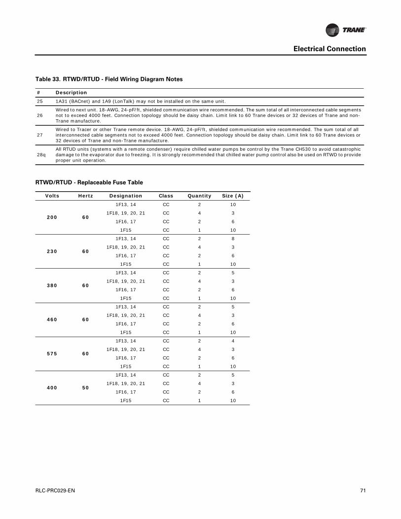
Electrical Connection
25 1A31 (BACnet) and 1A9 (LonTalk) may not be installed on the same unit.
26Wired to next unit. 18-AWG, 24-pF/ft, shielded communication wire recommended. The sum total of all interconnected cable segments not to exceed 4000 feet. Connection topology should be daisy chain. Limit link to 60 Trane devices or 32 devices of Trane and non-Trane manufacture.
27Wired to Tracer or other Trane remote device. 18-AWG, 24-pF/ft, shielded communication wire recommended. The sum total of all interconnected cable segments not to exceed 4000 feet. Connection topology should be daisy chain. Limit link to 60 Trane devices or 32 devices of Trane and non-Trane manufacture.
28qAll RTUD units (systems with a remote condenser) require chilled water pumps be control by the Trane CH530 to avoid catastrophic damage to the evaporator due to freezing. It is strongly recommended that chilled water pump control also be used on RTWD to provide proper unit operation.
RTWD/RTUD - Replaceable Fuse Table
Volts Hertz Designation Class Quantity Size (A)
200 60
1F13, 14 CC 2 10
1F18, 19, 20, 21 CC 4 3
1F16, 17 CC 2 6
1F15 CC 1 10
230 60
1F13, 14 CC 2 8
1F18, 19, 20, 21 CC 4 3
1F16, 17 CC 2 6
1F15 CC 1 10
380 60
1F13, 14 CC 2 5
1F18, 19, 20, 21 CC 4 3
1F16, 17 CC 2 6
1F15 CC 1 10
460 60
1F13, 14 CC 2 5
1F18, 19, 20, 21 CC 4 3
1F16, 17 CC 2 6
1F15 CC 1 10
575 60
1F13, 14 CC 2 4
1F18, 19, 20, 21 CC 4 3
1F16, 17 CC 2 6
1F15 CC 1 10
400 50
1F13, 14 CC 2 5
1F18, 19, 20, 21 CC 4 3
1F16, 17 CC 2 6
1F15 CC 1 10
Table 33. RTWD/RTUD - Field Wiring Diagram Notes
# Description
RLC-PRC029-EN 71
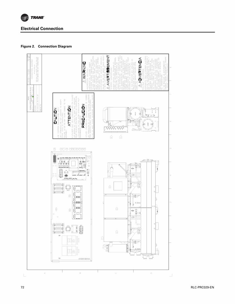
Electrical Connection
Figure 2. Connection Diagram
72 RLC-PRC029-EN

Electrical Connection
Table 34. RTWD/RTUD Connection Diagram Notes
# Description Additional Information
1 Line voltage entrance (see unit nameplate) location
2 Power section location
3 Controls section location
4 Customer control power high voltage entrance location
5 Customer control power low voltage entrance location
6 Condenser and chilled water flow inputs. optional 1A15, (5K10 and 5K9)
7Condenser and chilled water pump relay outputs. Separate 115/60/1or 220/50/1 customer power is required.
optional 1A14, (5K10 and 5K9)
8Unit status programmable relay outputs. Separate 115/60/1or 220/50/1 customer power is required.
optional 1A13, (5K12–5K19)
9Ice making status relay output. Separate 115/60/1or 220/50/1 customer power is required.
optional 1A12, (5K11)
10 External auto stop and emergency stop inputs. standard 1A5, (5K23 and 5K24)
11 External circuit lockout inputs circuit 1 and circuit 2. standard 1A6, (5K21 and 5K22)
12 External current-limit and chilled water setpoint or hot water inputs. optional 1A7, (4-20 mA or 2-10 V)
13 Condenser control and compressor % RLA input. optional 1A8, (4-20 mA or 0-10 V)
14 Tracer Communications optional 1A9
15 Ice machine control and heat mode control. optional 1A10, (5K20 and 5K25)
16 Circuit 1 disconnect optional 1A6
17 Circuit 2 disconnect optional 1A6
18 Wye-delta closed transition starter or across-the-line starter circuit 1A location
19 Wye-delta closed transition starter or across-the-line starter circuit 2A location
20Refer to RTWD/RTUD electrical schematic for specific electrical connection information and notes pertaining to wiring installation.
21 RTWD condenser control optional 1A8
22 Outdoor air temperature sensor optional (RTWD)
RLC-PRC029-EN 73
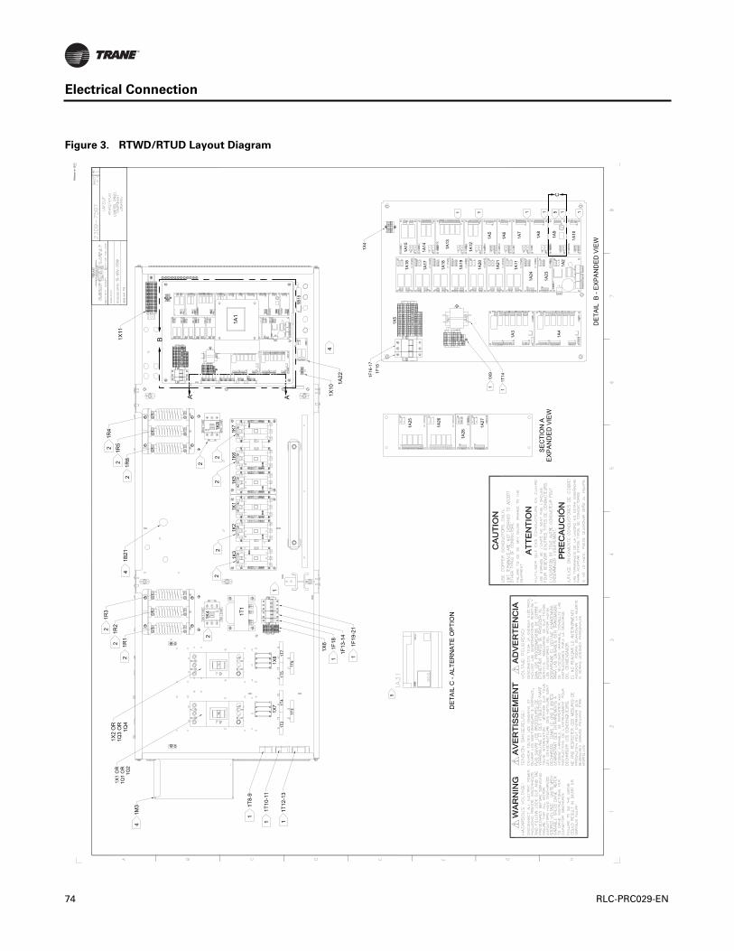
Electrical Connection
Figure 3. RTWD/RTUD Layout Diagram
SE
CTI
ON
AE
XP
AN
DE
DV
IEW
DE
TAIL
B-E
XP
AN
DE
DV
IEW
1F16
-17
1F15
1X9
1T14
1X4
1A25
1A26
1A28
1A27
1A3
1A4
1A16
1A17
1A18
1A19
1A20
1A21
1A11
1A24
1A23
1A2
1A101A
9
1A8
1A7
1A6
1A5
1A121A
13
1A14
1A15
1X5
1 1
111111
5
5C
DE
TAIL
C-A
LTE
RN
ATE
OP
TIO
N
A A
B1X11
1R4
1R5
1R6
1B21
1R3
1R2
1R1
1F18
1F13
-14
1F19
-21
1T8-
9
1T10
-11
1T12
-13
1X1
OR
1Q1
OR
1Q2
1X2
OR
1Q3
OR
1Q4
1K4 1T
1
1X6
1A1
1K8
1K3
1K2
1K1
1K5
1K6
1K7
5B18
1T2
1T4
1T3
1T5
1T7
1T6
1X7
1X82
2
2
42
2
2
1
1 1
2
1
1 1
22
22
2
4
1M3
4
1X10
1A22
C
AD
IVIS
ION
OF
AM
ER
ICAN
STAN
DAR
DIN
C.
ALL
RIG
HTS
RES
ERVE
D
Rel
ease
on
12/1
7
74 RLC-PRC029-EN
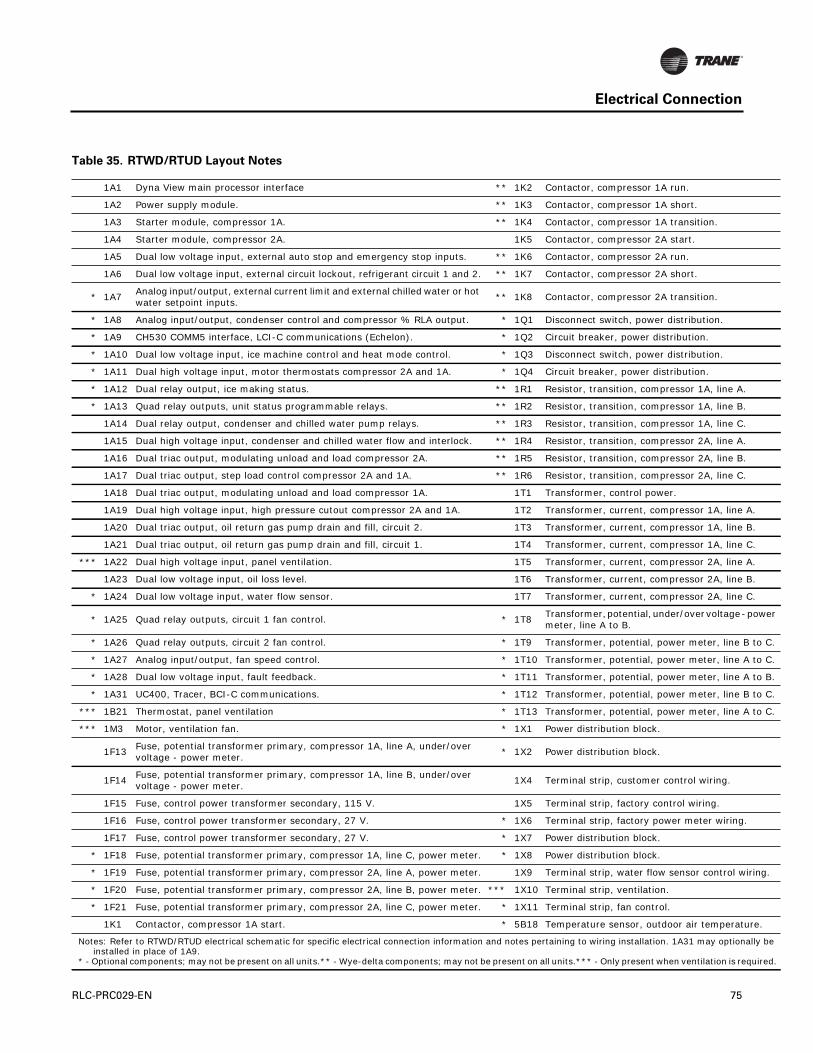
Electrical Connection
wer
o C.
o C.
o B.
o C.
o C.
ng.
.
y be
ired.
Table 35. RTWD/RTUD Layout Notes
1A1 Dyna View main processor interface ** 1K2 Contactor, compressor 1A run.
1A2 Power supply module. ** 1K3 Contactor, compressor 1A short.
1A3 Starter module, compressor 1A. ** 1K4 Contactor, compressor 1A transition.
1A4 Starter module, compressor 2A. 1K5 Contactor, compressor 2A start.
1A5 Dual low voltage input, external auto stop and emergency stop inputs. ** 1K6 Contactor, compressor 2A run.
1A6 Dual low voltage input, external circuit lockout, refrigerant circuit 1 and 2. ** 1K7 Contactor, compressor 2A short.
* 1A7Analog input/output, external current limit and external chilled water or hot water setpoint inputs.
** 1K8 Contactor, compressor 2A transition.
* 1A8 Analog input/output, condenser control and compressor % RLA output. * 1Q1 Disconnect switch, power distribution.
* 1A9 CH530 COMM5 interface, LCI-C communications (Echelon). * 1Q2 Circuit breaker, power distribution.
* 1A10 Dual low voltage input, ice machine control and heat mode control. * 1Q3 Disconnect switch, power distribution.
* 1A11 Dual high voltage input, motor thermostats compressor 2A and 1A. * 1Q4 Circuit breaker, power distribution.
* 1A12 Dual relay output, ice making status. ** 1R1 Resistor, transition, compressor 1A, line A.
* 1A13 Quad relay outputs, unit status programmable relays. ** 1R2 Resistor, transition, compressor 1A, line B.
1A14 Dual relay output, condenser and chilled water pump relays. ** 1R3 Resistor, transition, compressor 1A, line C.
1A15 Dual high voltage input, condenser and chilled water flow and interlock. ** 1R4 Resistor, transition, compressor 2A, line A.
1A16 Dual triac output, modulating unload and load compressor 2A. ** 1R5 Resistor, transition, compressor 2A, line B.
1A17 Dual triac output, step load control compressor 2A and 1A. ** 1R6 Resistor, transition, compressor 2A, line C.
1A18 Dual triac output, modulating unload and load compressor 1A. 1T1 Transformer, control power.
1A19 Dual high voltage input, high pressure cutout compressor 2A and 1A. 1T2 Transformer, current, compressor 1A, line A.
1A20 Dual triac output, oil return gas pump drain and fill, circuit 2. 1T3 Transformer, current, compressor 1A, line B.
1A21 Dual triac output, oil return gas pump drain and fill, circuit 1. 1T4 Transformer, current, compressor 1A, line C.
*** 1A22 Dual high voltage input, panel ventilation. 1T5 Transformer, current, compressor 2A, line A.
1A23 Dual low voltage input, oil loss level. 1T6 Transformer, current, compressor 2A, line B.
* 1A24 Dual low voltage input, water flow sensor. 1T7 Transformer, current, compressor 2A, line C.
* 1A25 Quad relay outputs, circuit 1 fan control. * 1T8Transformer, potential, under/over voltage - pometer, line A to B.
* 1A26 Quad relay outputs, circuit 2 fan control. * 1T9 Transformer, potential, power meter, line B t
* 1A27 Analog input/output, fan speed control. * 1T10 Transformer, potential, power meter, line A t
* 1A28 Dual low voltage input, fault feedback. * 1T11 Transformer, potential, power meter, line A t
* 1A31 UC400, Tracer, BCI-C communications. * 1T12 Transformer, potential, power meter, line B t
*** 1B21 Thermostat, panel ventilation * 1T13 Transformer, potential, power meter, line A t
*** 1M3 Motor, ventilation fan. * 1X1 Power distribution block.
1F13Fuse, potential transformer primary, compressor 1A, line A, under/over voltage - power meter.
* 1X2 Power distribution block.
1F14Fuse, potential transformer primary, compressor 1A, line B, under/over voltage - power meter.
1X4 Terminal strip, customer control wiring.
1F15 Fuse, control power transformer secondary, 115 V. 1X5 Terminal strip, factory control wiring.
1F16 Fuse, control power transformer secondary, 27 V. * 1X6 Terminal strip, factory power meter wiring.
1F17 Fuse, control power transformer secondary, 27 V. * 1X7 Power distribution block.
* 1F18 Fuse, potential transformer primary, compressor 1A, line C, power meter. * 1X8 Power distribution block.
* 1F19 Fuse, potential transformer primary, compressor 2A, line A, power meter. 1X9 Terminal strip, water flow sensor control wiri
* 1F20 Fuse, potential transformer primary, compressor 2A, line B, power meter. *** 1X10 Terminal strip, ventilation.
* 1F21 Fuse, potential transformer primary, compressor 2A, line C, power meter. * 1X11 Terminal strip, fan control.
1K1 Contactor, compressor 1A start. * 5B18 Temperature sensor, outdoor air temperature
Notes: Refer to RTWD/RTUD electrical schematic for specific electrical connection information and notes pertaining to wiring installation. 1A31 may optionallinstalled in place of 1A9.
* - Optional components; may not be present on all units.** - Wye-delta components; may not be present on all units.*** - Only present when ventilation is requ
RLC-PRC029-EN 75

Dimensions
Figure 5. RTWD/RTUD - 60 Hz Dimensions - 80-140 ton
10 9
13 14 15
2
1
3
411
5 6 8 7
12
12
A
G
H
C
D
E
F
N
RM
B
J
L
K
N
J
S
E( 3 pass evap )
2 pass evap
3 pass evap
( 3 pass evap )
(3 pass evap)
( 2 pass evap )
(2 pass evap)
76 RLC-PRC029-EN
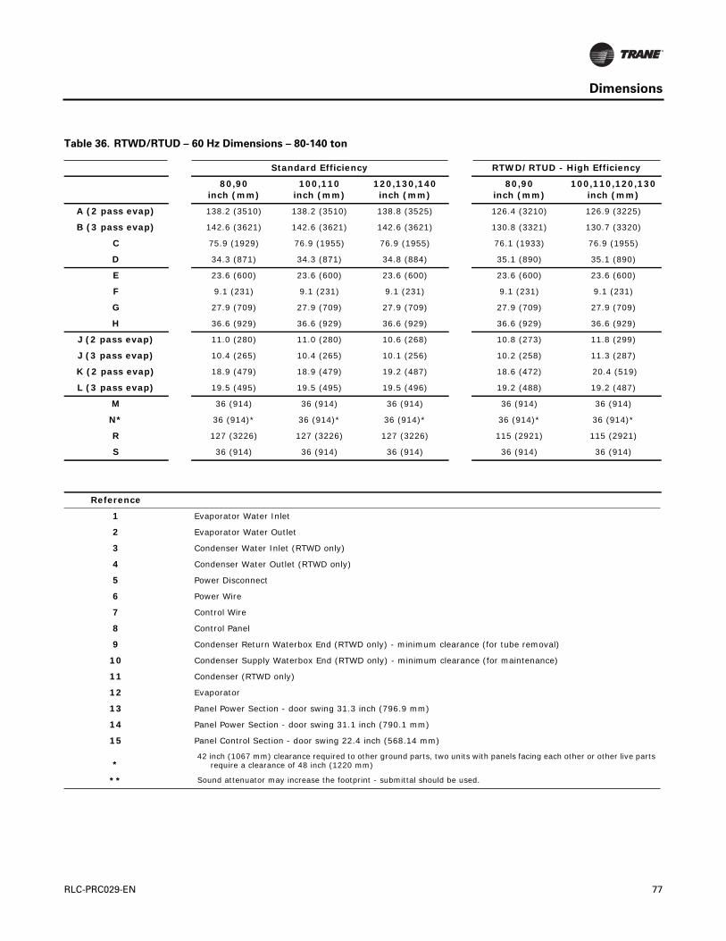
Dimensions
Table 36. RTWD/RTUD – 60 Hz Dimensions – 80-140 ton
Standard Efficiency RTWD/RTUD - High Efficiency
80,90inch (mm)
100,110inch (mm)
120,130,140inch (mm)
80,90inch (mm)
100,110,120,130inch (mm)
A (2 pass evap) 138.2 (3510) 138.2 (3510) 138.8 (3525) 126.4 (3210) 126.9 (3225)
B (3 pass evap) 142.6 (3621) 142.6 (3621) 142.6 (3621) 130.8 (3321) 130.7 (3320)
C 75.9 (1929) 76.9 (1955) 76.9 (1955) 76.1 (1933) 76.9 (1955)
D 34.3 (871) 34.3 (871) 34.8 (884) 35.1 (890) 35.1 (890)
E 23.6 (600) 23.6 (600) 23.6 (600) 23.6 (600) 23.6 (600)
F 9.1 (231) 9.1 (231) 9.1 (231) 9.1 (231) 9.1 (231)
G 27.9 (709) 27.9 (709) 27.9 (709) 27.9 (709) 27.9 (709)
H 36.6 (929) 36.6 (929) 36.6 (929) 36.6 (929) 36.6 (929)
J (2 pass evap) 11.0 (280) 11.0 (280) 10.6 (268) 10.8 (273) 11.8 (299)
J (3 pass evap) 10.4 (265) 10.4 (265) 10.1 (256) 10.2 (258) 11.3 (287)
K (2 pass evap) 18.9 (479) 18.9 (479) 19.2 (487) 18.6 (472) 20.4 (519)
L (3 pass evap) 19.5 (495) 19.5 (495) 19.5 (496) 19.2 (488) 19.2 (487)
M 36 (914) 36 (914) 36 (914) 36 (914) 36 (914)
N* 36 (914)* 36 (914)* 36 (914)* 36 (914)* 36 (914)*
R 127 (3226) 127 (3226) 127 (3226) 115 (2921) 115 (2921)
S 36 (914) 36 (914) 36 (914) 36 (914) 36 (914)
Reference
1 Evaporator Water Inlet
2 Evaporator Water Outlet
3 Condenser Water Inlet (RTWD only)
4 Condenser Water Outlet (RTWD only)
5 Power Disconnect
6 Power Wire
7 Control Wire
8 Control Panel
9 Condenser Return Waterbox End (RTWD only) - minimum clearance (for tube removal)
10 Condenser Supply Waterbox End (RTWD only) - minimum clearance (for maintenance)
11 Condenser (RTWD only)
12 Evaporator
13 Panel Power Section - door swing 31.3 inch (796.9 mm)
14 Panel Power Section - door swing 31.1 inch (790.1 mm)
15 Panel Control Section - door swing 22.4 inch (568.14 mm)
*42 inch (1067 mm) clearance required to other ground parts, two units with panels facing each other or other live parts
require a clearance of 48 inch (1220 mm)
** Sound attenuator may increase the footprint - submittal should be used.
RLC-PRC029-EN 77

Dimensions
Figure 6. RTWD/RTUD - 60 Hz Dimensions - 150-250 tons
A
K
B
L
P
3 pass evap
2 pass evap
( 3 pass evap )
(3 pass evap)
( 2 pass evap )
(2 pass evap)
(3 pass evap)
78 RLC-PRC029-EN
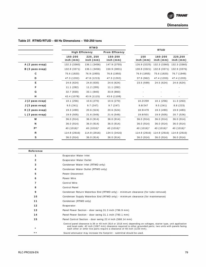
Dimensions
Table 37. RTWD/RTUD – 60 Hz Dimensions – 150-250 tons
RTWDRTUD
High Efficiency Prem Efficency
150-200inch (mm)
220, 250inch (mm)
150-200inch (mm)
150inch (mm)
160-200inch (mm)
220,250inch (mm)
A (2 pass evap) 132.3 (3360) 136.1 (3456) 147.9 (3755) 126.9 (3225) 132.3 (3360) 132.3 (3360)
B (3 pass evap) 132.8 (3371) 136.1 (3456) 150.9 (3831) 130.8 (3321) 132.8 (3371) 132.9 (3376)
C 75.6 (1920) 76.9 (1955) 76.8 (1950) 76.9 (1955) 75.6 (1920) 76.7 (1949)
D 47.3 (1202) 47.8 (1213) 47.3 (1202) 37.9 (962) 47.4 (1203) 47.4 (1203)
E 24.6 (624) 24.8 (630) 24.6 (624) 23.5 (599) 24.5 (624) 24.6 (624)
F 11.1 (282) 11.2 (295) 11.1 (282) - - -
G 32.7 (830) 33.1 (840) 33.8 (860) - - -
H 42.4 (1078) 43.9 (1115) 43.6 (1108) - - -
J (2 pass evap) 10.1 (256) 10.6 (270) 10.6 (270) 10.2/259 10.1 (256) 11.3 (263)
J (3 pass evap) 9.5 (241) 9.7 (247) 9.7 (247) 9.8/247 9.5 (241) 8.8 (223)
K (2 pass evap) 19.3 (490) 20.6 (524) 20.6 (524) 18.9/479 19.3 (490) 19.9 (483)
L (3 pass evap) 19.9 (505) 21.6 (549) 21.6 (549) 19.8/501 19.9 (505) 20.7 (526)
M 36.0 (914) 36.0 (914) 36.0 (914) 36.0 (914) 36.0 (914) 36.0 (914)
N 36.0 (914) 36.0 (914) 36.0 (914) 36.0 (914) 36.0 (914) 36.0 (914)
P* 40 (1016)* 40 (1016)* 40 (1016)* 40 (1016)* 40 (1016)* 40 (1016)*
R 114.8 (2916) 114.8 (2916) 134.5 (3416) 114.8 (2916) 114.8 (2916) 114.8 (2916)
S 36.0 (914) 36.0 (914) 36.0 (914) 36.0 (914) 36.0 (914) 36.0 (914)
Reference
1 Evaporator Water Inlet
2 Evaporator Water Outlet
3 Condenser Water Inlet (RTWD only)
4 Condenser Water Outlet (RTWD only)
5 Power Disconnect
6 Power Wire
7 Control Wire
8 Control Panel
9 Condenser Return Waterbox End (RTWD only) - minimum clearance (for tube removal)
10 Condenser Supply Waterbox End (RTWD only) - minimum clearance (for maintenance)
11 Condenser (RTWD only)
12 Evaporator
13 Panel Power Section - door swing 31.3 inch (796.9 mm)
14 Panel Power Section - door swing 31.1 inch (790.1 mm)
15 Panel Control Section - door swing 22.4 inch (568.14 mm)
*
Control panel clearance is 36 or 40 inch (914 or 1016 mm) depending on voltages, starter type, unit application and local code; 42 inch (1067 mm) clearance required to other grounded parts; two units with panels facing each other or other live parts require a clearance of 48 inch (1220 mm).
** Sound attenuator may increase the footprint - submittal should be used.
RLC-PRC029-EN 79

Dimensions
Figure 7. Unit Footprint
Table 38. RTWD/RTUD – unit footprint – all sizes
Standard EfficiencyHigh Efficiency200 PE (50 Hz)
Premium Efficiency
inch (mm) inch (mm) inch (mm)
P1 3.68 (93.5) 3.68 (93.5) 3.68 (93.5)
P2 123.78 (3144) 111.97 (2844) 131.65 (3344)
P3 2.43 (61.8) 4.30 (109.3) 4.30 (109.3)
P4 24.93 (633.2) 24.93 (633.2) 24.93 (633.2)
P5 2.5 (64) 2.5 (64) 2.5 (64)
Note: Base hole diameters all 0.63 inch (16 mm).
P5
80 RLC-PRC029-EN

Dimensions
Table 39. Weights – RTWD – 60 Hz – I-P units
Standard Efficiency High Efficiency Premium Efficiency
ModelOperating
Weight (lbs)Shipping
Weight (lbs)Operating
Weight (lbs)Shipping
Weight (lbs)Operating
Weight (lbs)Shipping Weight
(lbs)
80 5900 5703 5732 5551 - -
90 5933 5721 5792 5587 - -
100 6140 5902 6255 6025 - -
110 6332 6074 6475 6208 - -
120 6530 6248 6510 6230 - -
130 6535 6244 6543 6248 - -
140 6971 6649 - - - -
150 - - 7884 7544 8724 8243
160 - - 8395 8036 9171 8691
180 - - 8490 8098 9290 8772
200 - - 8578 8157 9337 8803
220 - - 9493 8995 - -
250 - - 10071 9478 - -
Note: Weights include optional base rail fork lifting, subtract 300 lbs if this option is not selected.
Table 40. Weights – RTWD – 60 Hz – SI units
Standard Efficiency High Efficiency Premium Efficiency
ModelOperating
Weight (kg)Shipping
Weight (kg)Operating
Weight (kg)Shipping
Weight (kg)Operating
Weight (kg)Shipping
Weight (kg)
80 2676 2587 2600 2518 - -
90 2691 2595 2627 2534 - -
100 2785 2677 2837 2733 - -
110 2872 2755 2937 2816 - -
120 2962 2834 2953 2826 - -
130 2964 2832 2968 2834 - -
140 3162 3016 - - - -
150 - - 3576 3422 3957 3739
160 - - 3808 3645 4160 3942
180 - - 3851 3673 4214 3979
200 - - 3891 3700 4235 3993
220 - - 4306 4080 - -
250 - - 4568 4299 - -
Note: Weights include optional base rail fork lifting, subtract 136.1 kg if this option is not selected.
RLC-PRC029-EN 81

Dimensions
Table 41. Weights - RTUD - 60 Hz
I-P units SI units
ModelOperating
Weight (lbs)Shipping
Weight (lbs)Operating
Weight (kg)Shipping
Weight (kg)
80 4874 4793 2211 2174
90 4892 4804 2219 2179
100 5073 4974 2301 2256
110 5326 5221 2416 2368
120 5322 5194 2414 2356
130 5322 5194 2414 2356
150 5917 5781 2684 2622
160 6804 6643 3086 3013
180 6876 6715 3119 3046
200 6980 6810 3166 3089
220 7300 7112 3311 3226
250 7602 7401 3448 3357
Note: Weights include optional base rail fork lifting, subtract 300 lbs if this option is not selected.
Table 42. Air-Cooled Condenser Weights
RTUDTonnage
I-P Units SI Units
Shipping Weight (lbs) Shipping Weight (kg)
Cond 1 Cond 2 Cond 1 Cond 2
80 2100 - 953 -
90 2651 - 1202 -
100 2884 - 1308 -
110 2950 - 1338 -
120 4005 - 1817 -
130 4046 - 1835 -
150 2044 2100 927 953
160 2100 2100 953 953
180 2100 2526 953 1146
200 2526 2526 1146 1146
220 2526 2884 1146 1308
250 2884 2884 1308 1308
82 RLC-PRC029-EN

Dimensions
Figure 8. Trane Air-Cooled Condenser - 80 ton, 150 ton (cond 1 & 2), 160 ton (cond 1 & 2), 180 ton (cond 1)
Figure 9. Trane Air-Cooled Condenser - 90 ton, 100 ton, 110 ton, 180 ton (cond 2), 200 ton (cond 1 & 2), 220
ton (cond 1 & 2), 250 ton (cond 1 & 2)
Approx. center of gravity
Disconnect switch
Service panel
Electrical boxsplit controls
Return bend cover
Inlet connection
Outlet connection
166.0”
90.5”
45.25”
93.0”
54.0” 54.0” 54.0”
166.0”
22.0”
90.5”
86.5”
58.5”
184.0”
64.0”
8.0”10.0”
0.75 inch anchor holes
Return bend cover
Electrical box
split controlsOutlet connection
Inlet connection
Service panel
Disconnect switch
220.0”
90.5”
45.25”
120.0”
Approx. center of gravity
108.0” 108.0”
220.0”
238.0”
22.0”
64.0” 58.5”
86.5”
90.5”
10.0”8.0”
0.75 inch anchor holes
RLC-PRC029-EN 83

Dimensions
Figure 10.Trane Air-Cooled Condenser - 120 ton, 130 ton
274.0”
45.25”
90.5”
145.0”
Approx. center of gravity
64.0”
86.5”
90.5”
Disconnect
switch
Electrical boxsplit controls
Returnbend cover
10.0” 108.0” 54.0” 108.0”
22.0”
8.0”274.0”
292.0”
Inlet connection
Outlet connection
58.5”
84 RLC-PRC029-EN
Mechanical Specifications
General
Exposed metal surfaces are painted with air-dry beige, direct-to-metal, single-component paint.RTWD units ship with full operating charges of refrigerant and oil. RTUD units ship with a fulloperating charge of oil and a nitrogen holding charge. Molded elastomeric isolation pads aresupplied for placement under all support points.
Trane air-cooled condenser structural elements and fan sections are galvanized steel.
Compressor and Motor
The unit is equipped with two semi-hermetic, direct-drive, 3600 rpm 60 Hz rotary compressors thatinclude a load/unload valve, rolling element bearings, oil filtration device and heater. The motoris a suction gas-cooled, hermetically sealed, two-pole squirrel cage induction motor. Oil separatordevice is provided separate from the compressor. Check valves in the compressor discharge andlube oil system and a solenoid valve in the lube system are also provided.
Unit-Mounted Starter
The unit is supplied with a UL 1995 indoor type enclosure with top power-wiring access and three-phase, overload protection. The starter is available in a wye-delta or across-the-line configuration,factory-mounted and fully pre-wired to the compressor motor and control panel. A factory-installed, factory-wired 820 VA control power transformer provides all unit control power (120 Vacsecondary) and Trane CH530 module power (24 Vac secondary). Optional starter features includecircuit breaker, high fault panel with circuit breaker, or mechanical, non-fused disconnect.
Evaporator
Dual circuited, shell and tube falling film evaporator design is used. Seamless internally finned,copper tubes are mechanically expanded into tube sheets and mechanically fastened to tubesupports. Evaporator tubes are 1.0 inch (25.4 mm) diameter on standard efficiency chillers and 0.75inch (19.05 mm) diameter on high and premium efficiency chillers. All tubes can be individuallyreplaced.
Shells and tube sheets are made of carbon steel. Designed, tested, and stamped in accordance withASME code. The evaporator is designed for refrigerant-side/working-side pressure of 200 psig(13.8 bars).
All water pass arrangements are available with grooved connections with 150 psig (10.5 bars)waterside working pressure. Waterside shall be hydrostatically tested at 225 psig (15.5 bars).
Condenser (RTWD only)
Dual circuited, shell and tube condenser designed with seamless internally/externally finned tubesexpanded into tube sheets and mechanically fastened to tube supports. Condenser tubes are 1.0inch (25.4 mm) diameter on standard efficiency chillers and 0.75 inch (19.05 mm) diameter on highand premium efficiency chillers. All tubes can be individually replaced.
Shells and tube sheets are made of carbon steel. Designed, tested, and stamped in accordance withASME code. The condenser is designed for refrigerant-side/working-side pressure of 300 psig (20.7bars).
Water side has single inlet and outlet piping connection. All water pass arrangements are availablewith grooved connections with 150 psig (10.5 bars) waterside working pressure. Waterside shallbe hydrostatically tested at 225 psig (15.5 bars).
Standard temperature condenser allows for leaving condenser water temperature up to 105°F(40.6°C) and for entering condenser water temperatures up to 95°F (35°C).
RLC-PRC029-EN 85
Mechanical Specifications
Condenser (Trane air-cooled only)
Air-cooled condenser coils have aluminum fins mechanically bonded to internally finned seamlesscopper tubing. The condenser coil has a subcooling circuit. Condensers are factory proof and leaktested at 400 psig (27.6 bars).
Direct-drive vertical discharge condenser fans are balanced. Three-phased condenser fan motorswith permanently lubricated ball bearings and inherent overheat protection in each phase areprovided.
Standard ambient units start and operate from 32°F to 125°F (0°C to 52°C).
Refrigerant Circuit
Each unit has two refrigerant circuits, with one rotary screw compressor per circuit. Eachrefrigerant circuit includes compressor suction and discharge service valves, removable core filter,charging port, sight glass and an electronic expansion valve. Modulating compressors andelectronic expansion valves provide variable capacity modulation over the entire building load andmaintain proper refrigerant flow.The RTWD also includes liquid line isolation valves andrefrigerant pressure relief valves installed on each circuit of both the evaporator and condenser.
For RTUD each refrigerant circuit also includes oil separator, oil cooler, and liquid line service valve(NOT isolation valve), and refrigerant pressure relief valve installed on each circuit of theevaporator (for the low side) and on each oil separator (for the high side). The discharge line leavingthe oil separator and liquid line entering the filters are capped and brazed.
Oil Management
The unit is configured with an oil management system that ensures proper oil circulationthroughout the unit. The key components of the system include an oil separator, oil filter and gaspump. An optional oil cooler is installed when the unit is used for high condensing temperatureor low evaporator temperature conditions. For example: remote condensers, heat recovery, water-to-water heat pump, ice making and low temperature process applications.
Unit Controls (Trane CH530)
The microprocessor-based control panel is factory-installed and factory-tested. The control systemis powered by a pre-wired control power transformer, and will load and unload the chiller throughadjustment of the compressor slide valve. Microprocessor-based chilled water reset based onreturn water is standard.
The Trane CH530 microprocessor automatically acts to prevent unit shutdown due to abnormaloperating conditions associated with low evaporator refrigerant temperature, high condensingtemperature, and/or motor current overload. If an abnormal operating condition continues and theprotective limit is reached, the machine will shut down.
The panel includes machine protection shutdown requiring manual reset for the followingconditions:
• Low evaporator refrigerant temperature and pressure
• High condenser refrigerant pressure
• Low oil flow
• Critical sensor or detection circuit faults
• Motor current overload
• High compressor discharge temperature
• Lost communication between modules
86 RLC-PRC029-EN

Mechanical Specifications
• Electrical distribution faults: phase loss, phase imbalance, or phase reversal
• External and local emergency stop
• Starter transition failure
The panel also includes machine protection shutdown with automatic reset for the followingcorrectable conditions:
• Momentary power loss
• Under/over voltage
• Loss of evaporator or condenser water flow
When a fault is detected, the control system conducts more than 100 diagnostic checks and displaysresults. The display will identify the fault, indicate date, time, and operating mode at time ofoccurrence, and provide type of reset required and a help message.
Clear Language Display Panel
Factory-mounted to the control panel door, the operator interface has an LCD touch-screen displayfor operator input and information output. This interface provides access to the followinginformation: evaporator report, condenser report, compressor report, ASHRAE Guideline 3 report,operator settings, service settings, service tests, and diagnostics. All diagnostics and messages aredisplayed in clear un-coded language.
Data contained in available reports includes:
• Water and air temperatures
• Refrigerant levels and temperatures
• Oil pressure
• Flow switch status
• EXV position
• Head pressure control command
• Compressor starts and run-time
• Line phase percent RLA, amps, and volts
All necessary settings and setpoints are programmed into the microprocessor-based controller viathe operator interface. The controller is capable of receiving signals simultaneously from a varietyof control sources, in any combination, and priority order of control sources can be programmed.The control source with priority determines active setpoints via the signal it sends to the controlpanel. Control sources may be:
• Local operator interface (standard)
• Time of day scheduling (optional capability available from local operator interface)
• Hard-wired 4-20 mA or 2-10 Vdc signal from an external source (interface optional; controlsource not supplied)
• LonTalk LCI-C (interface optional; control source not supplied)
• BACnet BCI-C (interface optional; control source not supplied)
• Trane Tracer Summit system (interface optional; control source not supplied)
Quality Assurance
The quality management system applied by Trane has been subject to independent third-partyassessment and approval to ISO 9001. The products described in this catalog are designed,manufactured and tested in accordance with the approved system requirements described in theTrane Quality Manual.
RLC-PRC029-EN 87
Mechanical Specifications
Electrical Options:
Across-the-Line Starter
Across-the-line starter is unit mounted with a UL 1995 gasketed enclosure.
Wye-Delta Starter
This option provides a reduced-inrush, unit mounted starter with a UL 1995 gasketed enclosure.Wye-delta starters are standard with 200–230 V machines.
Circuit Breaker
A molded case standard interrupting capacity circuit breaker, factory pre-wired with terminal blockpower connections and equipped with a lockable external operator handle, is available todisconnect the chiller from main power.
High Fault Rated Control Panel with Circuit Breaker
A molded case circuit breaker, factory pre-wired with terminal block power connections andequipped with a lockable external operator handle, is available to disconnect the chiller from mainpower. The control panel has a higher short circuit rating as determined by UL 508.
Non-Fused Disconnect
A non-fused molded case disconnect switch, factory pre-wired with terminal block powerconnections and equipped with a lockable external operator handle, is available to disconnect thechiller from main power.
Dual Point Power Connection
Unit is available with either dual or single point power connections.
Under/Over-Voltage Protection
Unit receives protection against variations in voltage (current lag and spike protection is standard).
Control Options:
A/C Fan Control (RTUD only)
Fan controls are integral to the chiller panel and shall manage the appropriate relays and variablespeed fan outputs to control the differential pressure.
BACnet Interface
BACnet communications capabilities are available, with communication link via single twisted-pairwiring to communication board.
Chilled Water Reset – Outdoor Air Temperature
Controls, sensors, and safeties allow reset of chilled water temperature, based on temperaturesignal, during periods of low outdoor air temperature (chilled water reset based on return chilledwater temperature is standard). Standard for RTUD units.
Condenser Leaving Water Temperature Control (RTWD only)
Enables the unit to use the leaving condenser water temperature to load and unload the chillerrelative to the leaving condenser water setpoint. The control system allows for a condenser leavingtemperature range of 80°F (26.7°C) to 140°F (60°C) with a water to water heat pump.
Condenser Differential Pressure Output (RTWD only)
Provides a 2–10 Vdc signal based on the system refrigerant differential pressure and time at thedifferential with customer defined endpoints.
88 RLC-PRC029-EN
Mechanical Specifications
Condenser Water Control Output (RTWD only)
Provides a highly configured signal designed to control a condenser water regulating valve.
External Chilled Water or Hot Water Setpoint
External chilled or hot water setpoint signal can be field wired to a factory-installed, testedinterface board through a 2–10 Vdc or 4–20 mA signal.
External Current-Limiting
External current-limit setpoint is communicated to a factory-installed, tested communication boardthrough a 2–10 Vdc or 4–20 mA signal.
LonTalk/Tracer Summit Interface
LonTalk (LCI-C) or Tracer Summit communications capabilities are available, with communicationlink via single twisted-pair wiring to factory-installed, tested communication board.
Low Ambient Fan Control - Two Speed (RTUD only)
The fan control shall provide for the first fan to be a two speed fan and the microprocessor can beprogrammed to control the low and high speed of that fan.
Low Ambient Fan Control - Variable Speed (RTUD only)
The fan control shall operate a fixed speed fan or a single inverter driven fan and the controlsinclude the enabling and speed command signals to the variable speed inverter.
Motor Current Analog Output
Control system indicates the active chiller percent of full run load amps, based on a 2–10 Vdc.
Power Meter
Tracks energy consumption (compressors only) with kWh meter.
Programmable Relays
Predefined, factory-installed, programmable relays allow the operator to select four relay outputs.Available outputs are: Alarm-Latching, Alarm-Auto Reset, General Alarm, Warning, Chiller LimitMode, Compressor Running, Head Pressure Relief Request, and Tracer Control.
Time of Day Scheduling
Time of day scheduling capabilities are available for scheduling single chiller applications throughTrance CH530 panel (without the need for building automation system-BAS). This feature allowsthe user to set up to 10 events in a 7 day time period.
Trane Air-Cooled Remote Condenser Options (RTUD only)
Low Ambient
Allows the condenser to start and operate down to 14°F and up to 125°F (-10°C-52°C).
Condenser Voltage
Voltages available 208-230, 460, and 575.
CompleteCoat Condenser Coil
Allows for the operation in coastal environments. This option includes condenser coil box coatingthat resists bi-metallic corrosion.
RLC-PRC029-EN 89
Mechanical Specifications
Other Options
Base Rail Forklifting
Channels built into the base frame allow for easy movement using a forklift
Dual Relief Valve
Unit comes with dual relief valves on both the high pressure side and low pressure side of eachrefrigerant circuit. Each dual relief valve configuration includes an isolation valve. Single reliefvalves are standard.
Flanged Water Connection Kit
Kit to convert all four water connections (RTWD units) or two water connections (RTUD units) fromgrooved pipe to flanged connections. This includes: grooved couplings, pipe offsets, and groovedto flange adapters.
Flow Switches - Factory Installed
Factory installed IFM effector flow switches for the evaporator and/or condenser.
Flow Switches - Field Installed
NEMA 1 or NEMA 4 150 psi flow switches ship with the unit.
High-Temperature Condenser
Optimized compressors, oil cooler and high condenser temperature control panel allows forleaving condenser water temperatures up to 140°F (60°C). This option is required for enteringcondenser water temperatures above 95°F (35°C).
Insulation
The evaporator, water boxes, and motor housing are covered with factory installed 0.75 inch (19.05mm) insulation. Factory installed foam insulation is used on the suction line, liquid level sensor,oil return system assembly (with its associated piping).
Insulation for High Humidity
The evaporator and water boxes are covered with factory installed 1.5 inch (38.1 mm) insulation.Factory installed foam insulation is used on the motor housing, suction line, liquid level sensor, andoil return system assembly (with its associated piping).
Isolators
Molded elastomeric isolators ship with the unit.
Low-Temperature Evaporator
Optimized compressors and oil cooler enable evaporator operation down to minimum leavingwater temperature of 10°F (-12.2°C).
Nitrogen Charge
Unit is shipped with a nitrogen holding charge in lieu of refrigerant (standard for RTUD).
90 RLC-PRC029-EN

Mechanical Specifications
Performance Tests
Performance and witness tests are available, based on requested operating points, to certify chillerperformance in accordance with AHRI Standard 550/590.
Rapid Restart™ Test
After completion of a standard full load witness test, power to the chiller will be cut and thenreapplied to demonstrate the chiller’s rapid restart capabilities for disaster relief.
Two-Way Condenser Water Regulating Valve (RTWD only)
For water regulation, a field-installed, 2-way butterfly-type (lug-style) valve, with integral electricaloperator and factory-mounted valve actuator, is available. The single-phase, dual frequency50 or60 Hz, motor can be selected with 115 V (can be powered directly from control power transformerat unit) or 220 V power. The 2-way valve is field-wired and controlled by the chiller regulating valvecontrol output. Valves are available in 3 and 4 inch (88.9 mm and 114.3 mm) sizes.
Seismic Rating - IBC
The unit is built and certified for seismic applications in accordance with the following InternationalBuilding Code (IBC) releases 2000, 2003, 2006 and 2009.
Seismic Rating - OSHPD
The unit is built and certified for seismic applications in accordance with OSHPD. The unit is factorymodified with reinforced steel anchors welded to the base.
Sound Reduction Package
Acoustical treatment for compressors can be factory or field installed.
Water-to-Water Heat Pump
Optimized compressors, oil cooler and high condenser temperature control panel allows forleaving condenser water temperatures up to 140°F (60°C). This option allows for enteringcondenser water temperatures above 95°F (35°C). Condenser leaving water temperature controloption is required; the setpoint range is 80°F (26.7°C) to 140°F (60°C).
RLC-PRC029-EN 91

Trane optimizes the performance of homes and buildings around the world. A business of Ingersoll Rand, theleader in creating and sustaining safe, comfortable and energy efficient environments, Trane offers a broadportfolio of advanced controls and HVAC systems, comprehensive building services, and parts.For more information, visit www.Trane.com.
Trane has a policy of continuous product and product data improvement and reserves the right to change design and specifications without notice.
We are committed to using environmentally
conscious print practices that reduce waste.
© 2012 Trane All rights reserved
RLC-PRC029-EN 20 Oct 2012
RLC-PRC029-EN (February 2010)