product data - alpinehomeair.com · product data a99338 fig. 1 ... residential and light commercial...
TRANSCRIPT
1
574ALEGACYt 13 SEER SINGLE--PACKAGED AIRCONDITIONER AND GAS FURNACE SYSTEMW/R--22 REFRIGERANT 1 AND 3 PHASE 1--1/2 TO 5NOMINAL TONS (SIZES 018--060)
Product Data
A99338
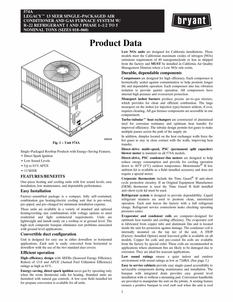
Fig. 1 -- Unit 574A
Single--Packaged Rooftop Products with Energy--Saving Features.S Direct Spark Ignition
S Low Sound Levels
S Up to 81% AFUE
S 13 SEER
FEATURES/BENEFITSOne--piece heating and cooling units with low sound levels, easyinstallation, low maintenance, and dependable performance.
Easy InstallationFactory--assembled package is a compact, fully self--contained,combination gas heating/electric cooling unit that is pre--wired,pre--piped, and pre--charged for minimum installation expense.
These units are available in a variety of standard and optionalheating/cooling size combinations with voltage options to meetresidential and light commercial requirements. Units arelightweight and install easily on a rooftop or at ground level. Thehigh--tech composite basepan eliminates rust problems associatedwith ground level applications.
Convertible duct configurationUnit is designed for easy use in either downflow or horizontalapplications. Each unit is easily converted from horizontal todownflow with the use of the two standard duct covers.
Efficient operationHigh--efficiency design with SEERs (Seasonal Energy EfficiencyRatios) of 13.0 and AFUE (Annual Fuel Utilization Efficiency)ratings as high as 81%.
Energy--saving, direct spark ignition saves gas by operating onlywhen the room thermostat calls for heating. Standard units arefurnished with natural gas controls. A low--cost field--installed kitfor propane conversion is available for all units.
Low NOx units are designed for California installations. Thesemodels meet the Californian maximum oxides of nitrogen (NOx)emissions requirement of 40 nanograms/joule or less as shippedfrom the factory and MUST be installed in California Air QualityManagement Districts where a Low NOx rule exists.
Durable, dependable componentsCompressors are designed for high efficiency. Each compressor ishermetically sealed against contamination to help promote longerlife and dependable operation. Each compressor also has vibrationisolation to provide quieter operation. All compressors haveinternal high pressure and overcurrent protection.
Monoport inshot burners produce precise air--to--gas mixture,which provides for clean and efficient combustion. The largemonoport on the inshot (or injection type) burners seldom, if ever,requires cleaning. All gas furnace components are accessible in onecompartment.
Turbo--tubulart heat exchangers are constructed of aluminizedsteel for corrosion resistance and optimum heat transfer forimproved efficiency. The tubular design permits hot gases to makemultiple passes across the path of the supply air.
In addition, dimples located on the heat exchanger walls force thehot gases to stay in close contact with the walls, improving heattransfer.
Direct--drive multi--speed, PSC (permanent split capacitor)blower motor is standard on all 574A models.
Direct--drive, PSC condenser--fan motors are designed to helpreduce energy consumption and provide for cooling operationdown to 40°F (4°C) outdoor temperature. Motormaster® II lowambient kit is available as a field--installed accessory and does notrequire a special motor.
Corporate thermostats include the Time Guard® II anti--shortcycle protection circuitry. If an Original Equipment Manufacture(OEM) thermostat is used the Time Guard II field installedanti--short cycle kit must be used.
Refrigerant system is designed to provide dependability. Liquidrefrigerant strainers are used to promote clean, unrestrictedoperation. Each unit leaves the factory with a full refrigerantcharge. Refrigerant service connections make checking operatingpressures easier.
Evaporator and condenser coils are computer--designed foroptimum heat transfer and cooling efficiency. The evaporator coilis fabricated from copper tube and aluminum fins and is locatedinside the unit for protection against damage. The condenser coil isinternally mounted on the top tier of the unit. A FIOP(Factory--Installed Option) metal louvered grille is available on allmodels. Copper fin coils and pre--coated fin coils are availablefrom the factory by special order. These coils are recommended inapplications where aluminum fins are likely to be damaged due tocorrosion. They are ideal for seacoast applications.
Low sound ratings ensure a quiet indoor and outdoorenvironment with sound ratings as low as 72dBA. (See page 3.)
Easy to service cabinets provide easy single--panel accessibility toserviceable components during maintenance and installation. Thebasepan with integrated drain provides easy ground levelinstallation with or without a mounting pad. Convenient handholdsare provided to manipulate the unit on the jobsite. A nesting featureensures a positive basepan to roof curb seal when the unit is roof

2
mounted. A convenient 3/4--in. (19 mm) wide perimeter flangemakes frame mounting on a rooftop easy.
Downflow operation is easily provided in the field to allowvertical ductwork connections. The basepan utilizes knockout styleseals on the bottom openings to ensure a positive seal in thehorizontal airflow mode.
Integrated Gas Control (IGC) board provides safe and efficientcontrol of heating and simplifies trouble--shooting through itsbuilt--in diagnostic function.
Cabinets are constructed of heavy--duty, phosphated, zinc--coatedprepainted steel capable of withstanding 500 hours in salt spray.Interior surfaces of the evaporator/heat exchanger compartment areinsulated with cleanable semi--rigid insulation board, which keepsthe conditioned air from being affected by the outdoor ambienttemperature and provides improved indoor air quality. (Conformsto American Society of Heating, Refrigeration and AirConditioning Engineers No. 62P.) The sloped drain minimizesstanding water in the drains which is provided with an externaldrain.
MODEL NUMBER NOMENCLATURE
574A --- ---018 A
Type of Unit574A --- Single Packaged
Air Conditioner andGas Furnace
Nominal Cooling Capacity018 --- 1---1/2 Tons024 --- 2.0 Tons030 --- 2.5 Tons036 --- 3.0 Tons042 --- 3.5 Tons048 --- 4.0 Tons060 --- 5.0 Tons
W
Heat Input Size (Btuh)040 --- 40,000060 --- 60,000090 --- 90,000115 --- 115,000130 --- 130,000
Electrical SupplyN --- 208/230---1---60P --- 208/230---3---60
040 A
Series
Options
AD --- Louver GrilleBT --- AL evap, vinyl condenserXT --- Louvered Grille and vinyl--- coated outdoor coil finCC --- Wire Grille, AL indoor and CU/CU outdoor coilsCU --- CU evap & condenserAC --- Louvered Grille, AL indoor and CU/CU outdoor coiAU --- Louvered Grille, CU/CU indoor and outdoor coils
See Price Page for full list of factory options.Only used if ordering an option
LEGENDAL --- AluminumCU --- Copper
N
Low NOx IndicatorA --- StandardN --- Low Nox
Fuel and ControlsW --- Natural Gas
574A
3
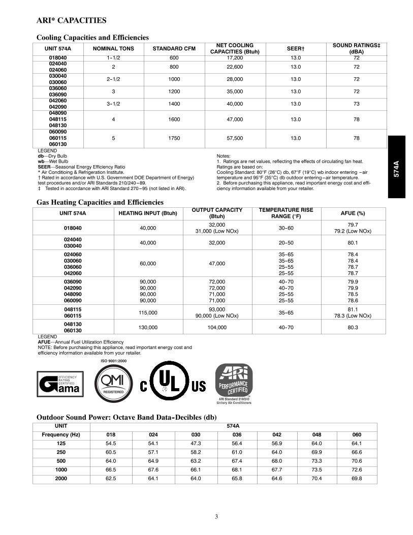
ARI* CAPACITIES
Cooling Capacities and EfficienciesUNIT 574A NOMINAL TONS STANDARD CFM
NET COOLINGCAPACITIES (Btuh) SEER†
SOUND RATINGS‡(dBA)
018040 1--1/2 600 17,200 13.0 72024040024060 2 800 22,600 13.0 72
030040030060 2--1/2 1000 28,000 13.0 72
036060036090 3 1200 35,000 13.0 72
042060042090 3--1/2 1400 40,000 13.0 73
048090048115048130
4 1600 47,000 13.0 78
060090060115060130
5 1750 57,500 13.0 78
LEGENDdb—Dry Bulbwb—Wet BulbSEER—Seasonal Energy Efficiency Ratio* Air Conditioing & Refrigeration Institute.{ Rated in accordance with U.S. Government DOE Department of Energy)test procedures and/or ARI Standards 210/240---89.} Tested in accordance with ARI Standard 270---95 (not listed in ARI).
Notes:1. Ratings are net values, reflecting the effects of circulating fan heat.Ratings are based on:Cooling Standard: 80°F ⟨26°C) db, 67°F (19°C) wb indoor entering ---airtemperature and 95°F (35°C) db outdoor entering---air temperature.2. Before purchasing this appliance, read important energy cost and effi-ciency information available from your retailer.
Gas Heating Capacities and EfficienciesUNIT 574A HEATING INPUT (Btuh)
OUTPUT CAPACITY(Btuh)
TEMPERATURE RISERANGE (°F) AFUE (%)
018040 40,00032,000
31,000 (Low NOx) 30--6079.7
79.2 (Low NOx)
024040030040 40,000 32,000 20--50 80.1
024060030060036060042060
60,000 47,000
35--6535--6525--5525--55
78.478.478.778.7
036090042090048090060090
90,00090,00090,00090,000
72,00072,00071,00071,000
40--7040--7025--5525--55
79.979.978.578.6
048115060115 115,000
93,00090,000 (Low NOx) 35--65
81.178.3 (Low NOx)
048130060130 130,000 104,000 40--70 80.3
LEGENDAFUE—Annual Fuel Utilization EfficiencyNOTE: Before purchasing this appliance, read important energy cost andefficiency information available from your retailer.
REGISTERED
ISO 9001:2000
ama
Outdoor Sound Power: Octave Band Data--Decibles (db)UNIT 574A
Frequency (Hz) 018 024 030 036 042 048 060
125 54.5 54.1 47.3 56.4 56.9 64.0 64.1
250 60.5 57.1 58.2 61.0 64.0 69.9 66.6
500 64.0 64.9 63.2 67.4 68.0 73.3 70.6
1000 66.5 67.6 66.1 68.1 67.7 73.5 72.6
2000 62.5 64.1 64.0 65.8 64.6 70.4 69.8
574A
4
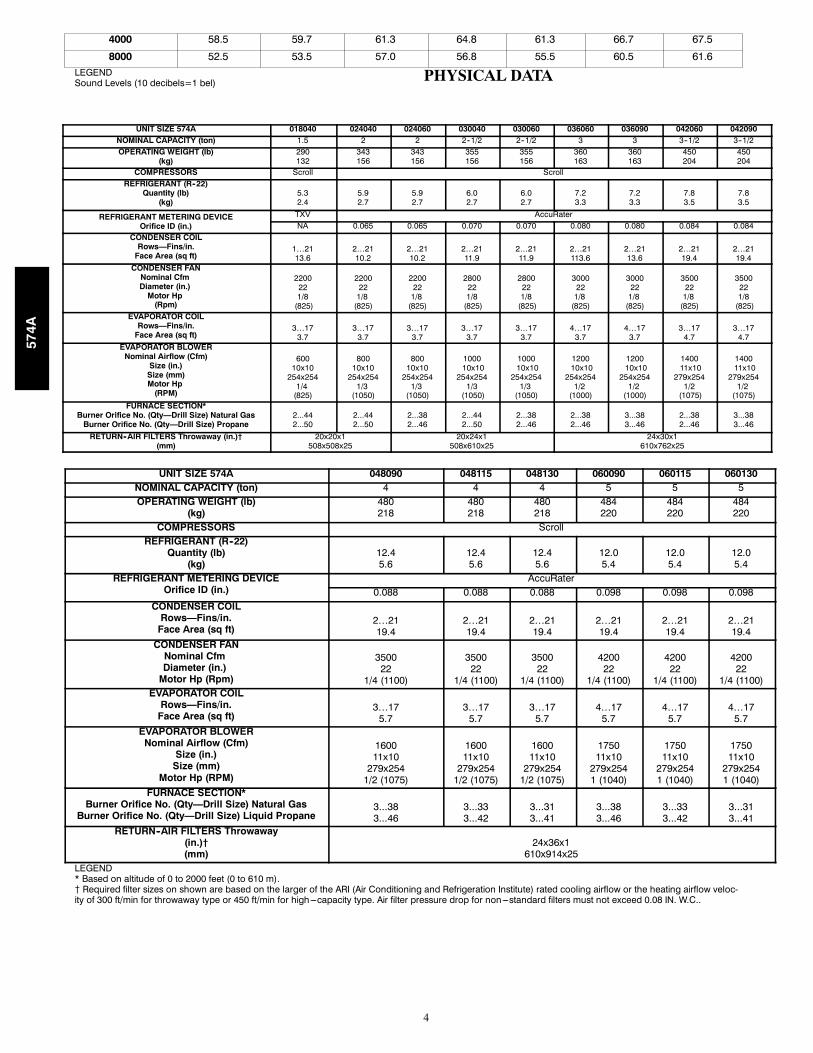
4000 58.5 59.7 61.3 64.8 61.3 66.7 67.5
8000 52.5 53.5 57.0 56.8 55.5 60.5 61.6
LEGENDSound Levels (10 decibels=1 bel) PHYSICAL DATA
UNIT SIZE 574A 018040 024040 024060 030040 030060 036060 036090 042060 042090NOMINAL CAPACITY (ton) 1.5 2 2 2--1/2 2--1/2 3 3 3--1/2 3--1/2OPERATING WEIGHT (lb)
(kg)290132
343156
343156
355156
355156
360163
360163
450204
450204
COMPRESSORS Scroll ScrollREFRIGERANT (R--22)
Quantity (lb)(kg)
5.32.4
5.92.7
5.92.7
6.02.7
6.02.7
7.23.3
7.23.3
7.83.5
7.83.5
REFRIGERANT METERING DEVICEOrifice ID (in.)
TXV AccuRaterNA 0.065 0.065 0.070 0.070 0.080 0.080 0.084 0.084
CONDENSER COILRows—Fins/in.
Face Area (sq ft)1…2113.6
2…2110.2
2…2110.2
2…2111.9
2…2111.9
2…21113.6
2…2113.6
2…2119.4
2…2119.4
CONDENSER FANNominal CfmDiameter (in.)
Motor Hp(Rpm)
2200221/8
(825)
220022
1/8(825)
220022
1/8(825)
2800221/8
(825)
2800221/8
(825)
300022
1/8(825)
300022
1/8(825)
350022
1/8(825)
3500221/8
(825)EVAPORATOR COIL
Rows—Fins/in.Face Area (sq ft)
3…173.7
3…173.7
3…173.7
3…173.7
3…173.7
4…173.7
4…173.7
3…174.7
3…174.7
EVAPORATOR BLOWERNominal Airflow (Cfm)
Size (in.)Size (mm)Motor Hp
(RPM)
60010x10
254x2541/4
(825)
80010x10
254x2541/3
(1050)
80010x10
254x2541/3
(1050)
100010x10
254x2541/3
(1050)
100010x10
254x2541/3
(1050)
120010x10
254x2541/2
(1000)
120010x10
254x2541/2
(1000)
140011x10
279x2541/2
(1075)
140011x10
279x2541/2
(1075)FURNACE SECTION*
Burner Orifice No. (Qty—Drill Size) Natural GasBurner Orifice No. (Qty—Drill Size) Propane
2...442...50
2...442...50
2...382...46
2...442...50
2...382...46
2...382...46
3...383...46
2...382...46
3...383...46
RETURN--AIR FILTERS Throwaway (in.)†(mm)
20x20x1508x508x25
20x24x1508x610x25
24x30x1610x762x25
UNIT SIZE 574A 048090 048115 048130 060090 060115 060130NOMINAL CAPACITY (ton) 4 4 4 5 5 5OPERATING WEIGHT (lb)
(kg)480218
480218
480218
484220
484220
484220
COMPRESSORS ScrollREFRIGERANT (R--22)
Quantity (lb)(kg)
12.45.6
12.45.6
12.45.6
12.05.4
12.05.4
12.05.4
REFRIGERANT METERING DEVICEOrifice ID (in.)
AccuRater0.088 0.088 0.088 0.098 0.098 0.098
CONDENSER COILRows—Fins/in.
Face Area (sq ft)2…2119.4
2…2119.4
2…2119.4
2…2119.4
2…2119.4
2…2119.4
CONDENSER FANNominal CfmDiameter (in.)
Motor Hp (Rpm)
350022
1/4 (1100)
350022
1/4 (1100)
350022
1/4 (1100)
420022
1/4 (1100)
420022
1/4 (1100)
420022
1/4 (1100)EVAPORATOR COIL
Rows—Fins/in.Face Area (sq ft)
3…175.7
3…175.7
3…175.7
4…175.7
4…175.7
4…175.7
EVAPORATOR BLOWERNominal Airflow (Cfm)
Size (in.)Size (mm)
Motor Hp (RPM)
160011x10
279x2541/2 (1075)
160011x10
279x2541/2 (1075)
160011x10
279x2541/2 (1075)
175011x10
279x2541 (1040)
175011x10
279x2541 (1040)
175011x10
279x2541 (1040)
FURNACE SECTION*Burner Orifice No. (Qty—Drill Size) Natural Gas
Burner Orifice No. (Qty—Drill Size) Liquid Propane3...383...46
3...333...42
3...313...41
3...383...46
3...333...42
3...313...41
RETURN--AIR FILTERS Throwaway(in.)†(mm)
24x36x1610x914x25
LEGEND* Based on altitude of 0 to 2000 feet (0 to 610 m).{ Required filter sizes on shown are based on the larger of the ARI (Air Conditioning and Refrigeration Institute) rated cooling airflow or the heating airflow veloc-ity of 300 ft/min for throwaway type or 450 ft/min for high---capacity type. Air filter pressure drop for non---standard filters must not exceed 0.08 IN. W.C..
574A

5
OPTIONS AND ACCESSORIESFactory--Installed OptionsLouvered grille provides hail and vandalism protection. A wiregrille is standard on all models. See model number nomenclaturefor louvered grille options.
Coil options include copper/copper and vinyl--coated constructionfor refrigerant coils. Units are shipped standard with coppertube/aluminum fin construction. See model number nomenclaturefor coil options.
Field--installed accessoriesEconomizer with Solid--State Controls and BarometricRelief DampersManual Air Damper (25% open)Filter RackFlat Roof Curbs (8--in. and 14--in.)Square--to--Round Duct Transition KitThermostatsControls Upgrade KitCrankcase HeaterCompressor Hard Start Kit (for use on single--phase units only)
Natural--to--propane Gas Conversion KitHigh Altitude Propane Conversion KitPropane--to--natural Gas Conversion KitRigging KitLow Ambient Kit (Motormaster® II Control)Solid--State Time Guard® II Device
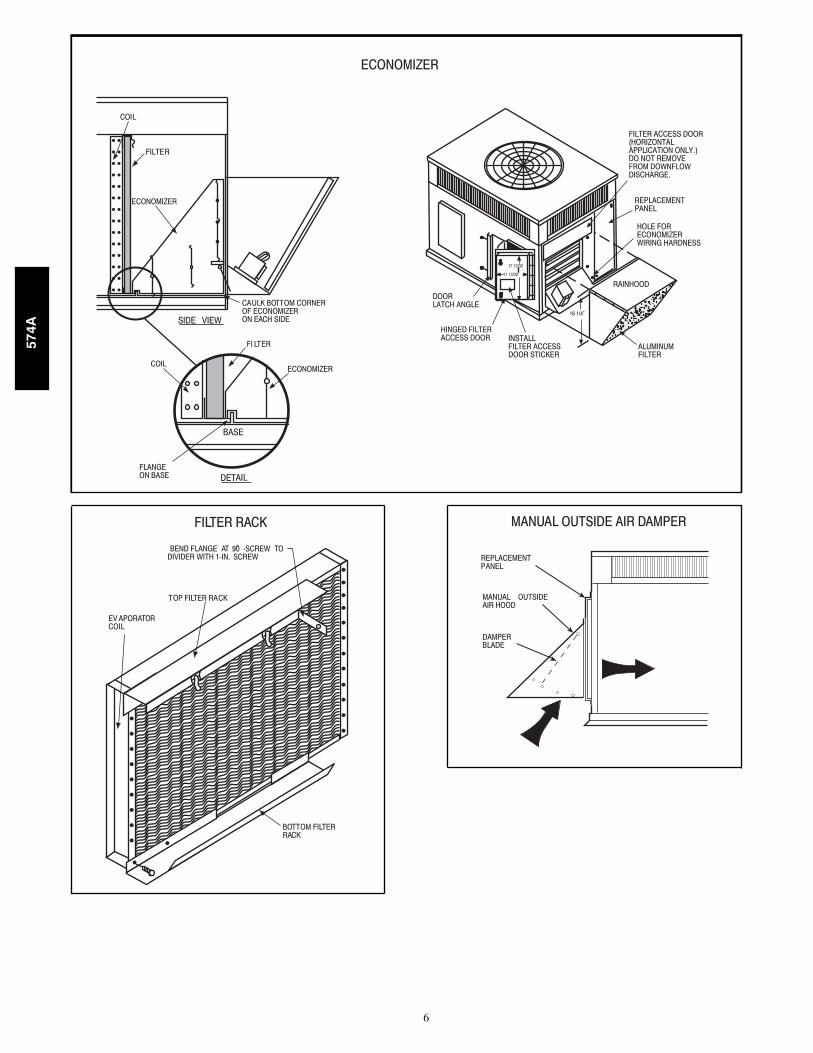
Economizer with solid--state controls and barometric reliefdampers includes filter racks and provide outdoor air duringcooling and reduce compressor operation.
Manual outside air damper includes hood and filter rack withadjustable damper blade for up to 25% outdoor air.
Flat roof curbs in both 8 in. (203 mm) and 14 in. (356 mm) sizesare available for roof mounted applications.
Square--to--round duct transition kit enables 018--048 size unitsto be fitted to 14 in. round ductwork.
Compressor hard start kit assists compressor start--up byproviding additional starting torque on single phase units andprolongs compressor motor life.
Corporate Thermostats provide control for the system heatingand cooling functions. Thermostat models are available in bothprogrammable and non--programmable versions.
Controls upgrade kit supplies high and low pressure safetyprotection and protects the unit from operating in unsuitableconditions.
Crankcase heater provides anti--floodback protection forlow--load cooling applications.
Natural--to--propane gas conversion kit allows for conversionfrom natural gas to propane gas for standard altitude (0 to 2000 ftabove sea level) (0 to 610 m).
Rigging kit includes lifting brackets which are inserted into theunit base rigging holds to lift unit for rooftop applications.
Low--ambient kit (Motormaster II control) allows the use ofmechanical cooling down to outdoor temperatures as low as 0_F(--17.8_C) when properly installed.
Solid--state Time Guard II device provides short--cyclingprotection for the compressor. Not required with corporateelectronic thermostats.
Filter rack features easy installation, serviceability, andhigh--filtering performance for vertical applications.
High altitude propane conversion kit is for use at 2001 to 6000ft (610 to 1829 m) above sea level. Kit consists of propane gasorifices that compensate for gas heat operation at high altitude.
Propane--to--natural conversion kit is for use at standardaltitudes (0 to 2000 ft above sea level)(0 to 610 m). Kit containsnatural gas orifices to convert the unit back to natural gas.
574A
6
ECONOMIZER
COIL
FILTER
SIDE VIEW
CAULK BOTTOM CORNEROF ECONOMIZERON EACH SIDE
BASE
COIL
FLANGEON BASE DETAIL
ECONOMIZER
FI LTER
FILTER ACCESS DOOR(HORIZONTALAPPLICATION ONLY.)DO NOT REMOVEFROM DOWNFLOWDISCHARGE.
REPLACEMENTPANEL
HOLE FORECONOMIZERWIRING HARDNESS
DOORLATCH ANGLE
HINGED FILTERACCESS DOOR INSTALL
FILTER ACCESSDOOR STICKER
ALUMINUMFILTER
RAINHOOD11 13/32”�
17 13/32
16 1/4”�
EV APORATORCOIL
TOP FILTER RACK
BEND FLANGE AT 90̊�-SCREW TODIVIDER WITH 1-IN. SCREW
BOTTOM FILTERRACK
DAMPERBLADE
MANUAL OUTSIDEAIR HOOD
REPLACEMENTPANEL
ECONOMIZER
FILTER RACK MANUAL OUTSIDE AIR DAMPER
574A
7
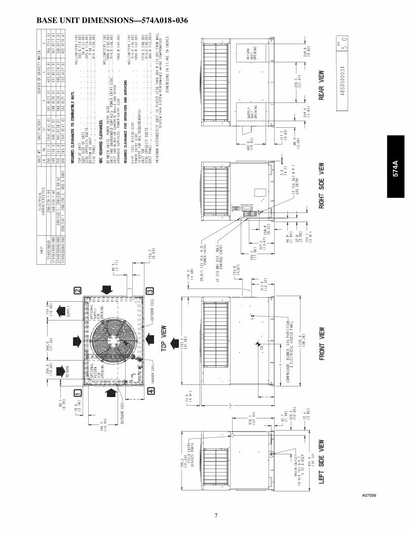
BASE UNIT DIMENSIONS—574A018--036
A07599
574A
8
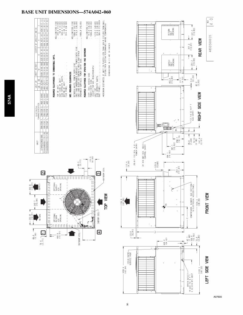
BASE UNIT DIMENSIONS—574A042--060
A07600
574A

9
ACCESSORY ROOF CURB
Gask et aroundouter edge
Insulateddeck pan
Gask et aroundduct
S/AR/A
HVAC unitbase
*Gask etingouter flange
Flashing fieldsupplied
Roofing materialfield supplied
Cant str ipfield supplied
*Provided with roof curb
Roof
Ductworkfield supplied
Insulation (fieldsupplied)
Roof curb*
Wood nailer*
Gask etinginner flange*
Scre w(NO TE A)
Roof Curb for Small Cabinet
Note A: When unit mounting scre w is used,retainer bra cke t must also be used.
HVAC unitbase
*Gask etingouter flange
Flashing fieldsupplied
Roofing materialfield supplied
Cant str ipfield supplied
*Provided with roof curb
Roof
Ductworkfield supplied
Insulation (fieldsupplied)
Roof curb*
Wood nailer*
Gask etinginner flange*
Scre w(NOTE A)
Roof Curb for Large Cabinet
Note A: When unit mounting scre w is used,retainer bra cket must also be used.
A
B Typ.
Supply opening(B x C)
LongSupport
D
F
Return opening(B X C)
Insulateddeck pan
ShortSupport
C Typ.
G
E
F
G
DE
A05308
UNIT SIZE ODS CATALOGNUMBER
AIN. (MM)
BIN. (MM)
CIN. (MM)
DIN. (MM)
EIN. (MM)
FIN. (MM)
GIN. (MM)
574A018--036CPRFCURB006A00 8 (203) 11 (279) 16--1/2 (419) 28--3/4 (730) 30--3/8 (771) 44--5/16 (1126) 45--15/16 (1167)CPRFCURB007A00 14 (356) 11 (279) 16--1/2 (419) 28--3/4 (730) 30--3/8 (771) 44--5/16 (1126) 45--15/16 (1167)
574A042--060CPRFCURB008A00 8 (203) 16--3/16 (411) 17--3/8 (441) 40--1/4 (1022) 41--15/16 (1065) 44--7/16 (1129) 46--1/16 (1169)CPRFCURB009A00 14 (356) 16--3/16 (411) 17--3/8 (441) 40--1/4 (1022) 41--15/16 (1065) 44--7/16 (1129) 46--1/16 (1169)
NOTES:1. Roof curb must be set up for unit being installed.
2. Seal strip must be applied, as required, to unit being installed.
3. Dimensions are in inches.
4. Dimension in ( ) are in millimeters.
5. Roof curb is made of 16--gauge steel.
6. Attach ductwork to curb (flanges of duct rest on curb).
7. Insulated panels: 1--in. (25 mm) thick fiberglass 1 lb. density.
8. When unit mounting screw is used (see Note A), a retainer bracket must be used as well. This bracket must also be used when required by code for hurricane or seismicconditions. This bracket is available through Micrometl.
574A

10
574A CORNER WEIGHTS
1 2
4 3C00070B
DETAIL A
A05161
CORNER WEIGHTS (SMALL CABINET) CORNER WEIGHTS (LARGE CABINET)
Unit018 024 030 036
Unit042 048 060
lb kg lb kg lb kg lb kg lb kg lb kg lb kg
Unit OnlyWeight 290 132 343 156 355 161 360 163 Unit Only
Weight 450 204 480 218 484 220
Corner Weight 1 75 34 69 31 75 34 74 34 Corner Weight 1 90 41 97 44 98 45
Corner Weight 2 62 28 53 24 56 25 55 25 Corner Weight 2 72 33 74 34 75 34
Corner Weight 3 97 44 83 38 81 37 86 39 Corner Weight 3 110 50 116 53 118 54
Corner Weight 4 56 25 138 63 143 65 145 66 Corner Weight 4 178 81 193 88 193 88
Rigging Weight 309 140 353 160 365 166 370 168 Rigging Weight 465 211 495 225 499 226
Shipping Weight 344 156 383 173 395 179 400 181 Shipping Weight 510 231 540 245 544 247
SELECTION PROCEDURE (WITH EXAMPLE)1. Determine cooling and heating requirements atdesign conditions:Given:
Required Cooling Capacity (TC) 34,000 Btuh. . . . . . . . . .
Sensible Heat Capacity (SHC) 25,000 Btuh. . . . . . . . . . . .
Required Heating Capacity .60,000 Btuh. . . . . . . . . . . . . . .
Condenser Entering Air Temperature 95°F (35°C). . . . . . .
Indoor--Air Temperature 80°F (26°C) edb 67°F (19°C) ewb
Evaporator Air Quantity 1200 CFM. . . . . . . . . . . . . . . . . .
External Static Pressure 0.1 IN. W.C.. . . . . . . . . . . . . . . . . .
Electrical Characteristics 208--1--60. . . . . . . . . . . . . . . . . . .
2. Select unit based on required cooling capacity.Enter Net Cooling Capacities table at outdoor entering temperatureof 95°F (35°C). Unit 574A036 at 1200 cfm and 67°F (19°C) ewb(entering wet bulb) will provide a total capacity of 36,000 Btuhand a SHC of 27,400 Btuh. Calculate SHC correction, if required,using Note 4 under Cooling Capacities tables.
3. Select heating capacity of unit to provide designcondition requirement.In the Heating Capacities and Efficiencies table on page 4, note thatthe unit 574A036090 will provide 72,000 Btuh with an input of90,000 Btuh.
4. Determine fan speed and power requirements atdesign conditions.Before entering the air delivery tables, calculate the total staticpressure required. From the given example, the Wet Coil PressureDrop Table, and the Filter Pressure Drop table on page 16, find at1200 cfm:
External Static Pressure 0.10 IN. W. C.
Wet Coil 0.059 IN. W.C.
Filter 0.13 IN. W.C.
Total Static Pressure 0.29 IN. W.C.
Enter the table for Dry Coil Air Delivery—horizontal anddownflow Discharge on page 15. For 208 v operation, deduct 10%from the value given. At 0.33 ESP (external static pressure), the fanwill deliver about 1404 cfm at medium speed. The fan speedshould be set at medium speed.
5. Select unit that corresponds to power sourceavailable.The Electrical Data table on page 21 shows that the unit is
designed to operate at 208--1--60.
574A
11
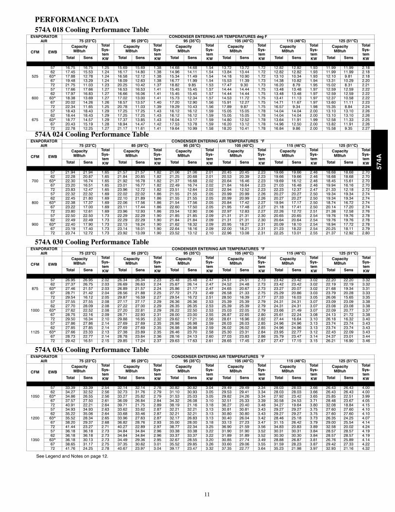
PERFORMANCE DATA574A 018 Cooling Performance Table
EVAPORATORAIR
CONDENSER ENTERING AIR TEMPERATURES deg F75 (23°C) 85 (29°C) 95 (35°C) 105 (40°C) 115 (46°C) 125 (51°C)
CFM EWBCapacityMBtuh
TotalSys-temKW
CapacityMBtuh
TotalSys-temKW
CapacityMBtuh
TotalSys-temKW
CapacityMBtuh
TotalSys-temKW
CapacityMBtuh
TotalSys-temKW
CapacityMBtuh
TotalSys-temKWTotal Sens Total Sens Total Sens Total Sens Total Sens Total Sens
525
57 16.75 16.75 1.25 15.69 15.69 1.38 14.68 14.68 1.54 13.72 13.72 1.72 12.82 12.82 1.93 11.99 11.99 2.1862 17.45 15.53 1.24 16.17 14.80 1.38 14.96 14.11 1.54 13.84 13.44 1.72 12.82 12.82 1.93 11.99 11.99 2.1863* 17.88 12.78 1.24 16.58 12.12 1.38 15.34 11.49 1.54 14.18 10.90 1.72 13.10 10.34 1.93 12.10 9.81 2.1867 19.48 13.29 1.24 18.09 12.63 1.38 16.77 11.99 1.54 15.53 11.39 1.73 14.38 10.82 1.94 13.31 10.29 2.2072 21.75 11.03 1.23 20.25 10.42 1.37 18.82 9.85 1.53 17.47 9.30 1.73 16.20 8.79 1.95 15.02 8.31 2.21
600
57 17.66 17.66 1.27 16.53 16.53 1.41 15.45 15.45 1.57 14.44 14.44 1.75 13.48 13.48 1.97 12.59 12.59 2.2262 17.97 16.83 1.27 16.66 16.06 1.41 15.45 15.45 1.57 14.44 14.44 1.75 13.48 13.48 1.97 12.59 12.59 2.2263* 18.38 13.69 1.27 17.02 13.00 1.41 15.73 12.34 1.57 14.53 11.72 1.75 13.41 11.13 1.97 12.37 10.58 2.2267 20.02 14.26 1.26 18.57 13.57 1.40 17.20 12.90 1.56 15.91 12.27 1.75 14.71 11.67 1.97 13.60 11.11 2.2372 22.34 11.65 1.25 20.78 11.03 1.39 19.29 10.43 1.56 17.89 9.87 1.75 16.57 9.34 1.98 15.35 8.84 2.24
675
57 18.43 18.43 1.29 17.25 17.25 1.43 16.12 16.12 1.59 15.05 15.05 1.78 14.04 14.04 2.00 13.10 13.10 2.2662 18.44 18.43 1.29 17.25 17.25 1.43 16.12 16.12 1.59 15.05 15.05 1.78 14.04 14.04 2.00 13.10 13.10 2.2663* 18.77 14.57 1.29 17.37 13.85 1.43 16.04 13.17 1.59 14.80 12.52 1.78 13.64 11.91 1.99 12.58 11.33 2.2567 20.43 15.19 1.28 18.94 14.47 1.42 17.53 13.78 1.59 16.20 13.12 1.78 14.96 12.50 2.00 13.82 11.91 2.2672 22.78 12.25 1.27 21.17 11.61 1.41 19.64 10.99 1.58 18.20 10.41 1.78 16.84 9.86 2.00 15.58 9.35 2.27
574A 024 Cooling Performance TableEVAPORATOR
AIRCONDENSER ENTERING AIR TEMPERATURES °F
75 (23°C) 85 (29°C) 95 (35°C) 105 (40°C) 115 (46°C) 125 (51°C)
CFM EWBCapacityMBtuh
TotalSys-temKW
CapacityMBtuh
TotalSys-temKW
CapacityMBtuh
TotalSys-temKW
CapacityMBtuh
TotalSys-temKW
CapacityMBtuh
TotalSys-temKW
CapacityMBtuh
TotalSys-temKWTotal Sens Total Sens Total Sens Total Sens Total Sens Total Sens
700
57 21.94 21.94 1.65 21.57 21.57 1.82 21.06 21.06 2.01 20.45 20.45 2.23 19.66 19.66 2.46 18.68 18.68 2.7062 22.28 20.87 1.65 21.84 20.85 1.82 21.25 20.68 2.01 20.53 20.39 2.23 19.66 19.66 2.46 18.68 18.68 2.7063* 22.30 16.74 1.65 21.92 16.78 1.82 21.37 16.68 2.02 20.64 16.46 2.23 19.69 16.12 2.46 18.45 15.61 2.7067 23.20 16.51 1.65 23.01 16.77 1.82 22.49 16.74 2.02 21.84 16.64 2.23 21.03 16.48 2.46 19.94 16.16 2.7072 23.83 12.47 1.65 23.96 12.72 1.82 23.51 12.64 2.02 22.94 12.52 2.23 22.23 12.37 2.47 21.33 12.18 2.72
800
57 22.32 22.32 1.69 22.02 22.02 1.86 21.55 21.55 2.05 20.99 20.99 2.26 20.27 20.27 2.50 19.34 19.34 2.7462 22.45 21.80 1.69 22.10 21.89 1.86 21.55 21.55 2.05 20.99 20.99 2.26 20.27 20.27 2.50 19.34 19.34 2.7463* 22.38 17.37 1.69 22.06 17.56 1.86 21.54 17.56 2.05 20.84 17.42 2.27 19.94 17.17 2.50 18.74 16.72 2.7467 23.22 17.00 1.69 23.11 17.44 1.86 22.60 17.50 2.05 21.95 17.48 2.27 21.18 17.41 2.50 20.14 17.20 2.7472 23.80 12.61 1.69 23.96 12.93 1.86 23.54 12.90 2.06 22.97 12.83 2.27 22.26 12.72 2.51 21.38 12.58 2.76
900
57 22.50 22.50 1.73 22.29 22.29 1.90 21.85 21.85 2.09 21.31 21.31 2.30 20.65 20.65 2.54 19.76 19.76 2.7862 22.49 22.49 1.73 22.29 22.29 1.90 21.84 21.84 2.09 21.31 21.31 2.30 20.64 20.64 2.54 19.76 19.76 2.7863* 22.40 17.90 1.73 22.13 18.24 1.90 21.62 18.32 2.09 20.95 18.27 2.31 20.09 18.10 2.54 18.94 17.72 2.7867 23.19 17.40 1.73 23.14 18.01 1.90 22.64 18.16 2.09 22.00 18.21 2.31 21.23 18.22 2.54 20.25 18.11 2.7972 23.74 12.72 1.73 23.92 13.09 1.90 23.52 13.12 2.10 22.96 13.08 2.31 22.25 13.01 2.55 21.37 12.92 2.80
574A 030 Cooling Performance TableEVAPORATOR
AIRCONDENSER ENTERING AIR TEMPERATURES °F
75 (23°C) 85 (29°C) 95 (35°C) 105 (40°C) 115 (46°C) 125 (51°C)
CFM EWBCapacityMBtuh
TotalSys-temKW
CapacityMBtuh
TotalSys-temKW
CapacityMBtuh
TotalSys-temKW
CapacityMBtuh
TotalSys-temKW
CapacityMBtuh
TotalSys-temKW
CapacityMBtuh
TotalSys-temKWTotal Sens Total Sens Total Sens Total Sens Total Sens Total Sens
875
57 26.95 26.95 2.02 26.34 26.34 2.23 25.48 25.48 2.47 24.51 24.51 2.73 23.42 23.42 3.02 22.20 22.20 3.3262 27.37 26.75 2.03 26.69 26.63 2.24 25.67 26.14 2.47 24.52 24.48 2.73 23.42 23.42 3.02 22.19 22.19 3.3263* 27.46 21.57 2.03 26.89 21.57 2.24 25.86 21.17 2.47 24.65 20.67 2.73 23.27 20.07 3.02 21.68 19.34 3.3167 28.71 21.42 2.04 28.56 21.88 2.25 27.72 21.73 2.49 26.58 21.33 2.75 25.29 20.86 3.03 23.79 20.28 3.3372 29.54 16.12 2.05 29.87 16.59 2.27 29.54 16.72 2.51 28.50 16.39 2.77 27.33 16.03 3.05 26.06 15.65 3.35
1000
57 27.55 27.55 2.08 27.17 27.17 2.29 26.36 26.36 2.53 25.39 25.39 2.79 24.31 24.31 3.07 23.09 23.09 3.3862 27.70 28.09 2.08 27.22 27.00 2.29 26.35 26.35 2.53 25.39 25.39 2.79 24.31 24.31 3.07 23.08 23.08 3.3863* 27.62 22.52 2.08 27.20 22.81 2.29 26.22 22.50 2.53 25.03 22.05 2.79 23.66 21.49 3.07 22.09 20.77 3.3767 28.75 22.16 2.09 28.71 22.93 2.31 28.00 23.00 2.55 26.87 22.65 2.80 25.61 22.24 3.08 24.13 21.72 3.3872 29.50 16.34 2.10 29.88 16.95 2.32 29.62 17.21 2.56 28.61 16.96 2.82 27.44 16.64 3.10 26.18 16.32 3.40
1125
57 27.86 27.86 2.14 27.69 27.69 2.35 26.98 26.98 2.59 26.03 26.03 2.85 24.96 24.96 3.13 23.74 23.74 3.4362 27.85 27.85 2.14 27.69 27.69 2.35 26.98 26.98 2.59 26.02 26.02 2.85 24.96 24.96 3.13 23.74 23.74 3.4363* 27.66 23.33 2.13 27.38 23.89 2.35 26.46 23.70 2.58 25.30 23.31 2.84 23.95 22.77 3.12 22.43 22.09 3.4367 28.73 22.77 2.14 28.78 23.84 2.36 28.16 24.13 2.60 27.03 23.83 2.86 25.79 23.47 3.14 24.37 23.01 3.4472 29.42 16.51 2.15 29.85 17.24 2.37 29.63 17.63 2.61 28.65 17.45 2.87 27.47 17.15 3.15 26.21 16.90 3.46
574A 036 Cooling Performance TableEVAPORATOR
AIRCONDENSER ENTERING AIR TEMPERATURES °F
75 (23°C) 85 (29°C) 95 (35°C) 105 (40°C) 115 (46°C) 125 (51°C)
CFM EWBCapacityMBtuh
TotalSys-temKW
CapacityMBtuh
TotalSys-temKW
CapacityMBtuh
TotalSys-temKW
CapacityMBtuh
TotalSys-temKW
CapacityMBtuh
TotalSys-temKW
CapacityMBtuh
TotalSys-temKWTotal Sens Total Sens Total Sens Total Sens Total Sens Total Sens
1050
57 33.39 33.39 2.54 32.14 32.14 2.78 30.82 30.82 3.04 29.49 29.49 3.34 28.03 28.03 3.66 26.43 26.43 4.0062 34.27 32.52 2.56 32.73 31.76 2.79 31.10 30.93 3.05 29.53 29.41 3.34 28.03 28.03 3.66 26.43 26.43 4.0063* 34.86 26.55 2.56 33.27 25.82 2.79 31.53 25.03 3.05 29.82 24.26 3.34 27.92 23.42 3.65 25.85 22.51 3.9967 37.57 27.50 2.61 36.09 26.84 2.84 34.32 26.08 3.10 32.51 25.33 3.39 30.58 24.53 3.71 28.48 23.67 4.0572 40.91 22.21 2.64 39.71 21.75 2.89 38.19 21.16 3.18 36.27 20.40 3.48 34.27 19.64 3.80 32.08 18.84 4.15
1200
57 34.93 34.93 2.63 33.62 33.62 2.87 32.21 32.21 3.13 30.81 30.81 3.43 29.27 29.27 3.75 27.60 27.60 4.1062 35.22 35.06 2.64 33.68 33.46 2.87 32.21 32.21 3.13 30.80 30.80 3.43 29.27 29.27 3.75 27.60 27.60 4.1063* 35.52 28.34 2.65 33.96 27.63 2.87 32.17 26.83 3.13 30.40 26.04 3.42 28.46 25.18 3.73 26.35 24.25 4.0767 38.20 29.37 2.68 36.82 28.76 2.93 35.00 28.00 3.18 33.13 27.23 3.47 31.15 26.42 3.79 29.00 25.54 4.1472 41.44 23.27 2.71 40.27 22.89 2.97 38.77 22.34 3.25 36.90 21.59 3.56 34.83 20.83 3.89 32.58 20.02 4.24
1350
57 36.18 36.18 2.73 34.84 34.84 2.96 33.38 33.38 3.22 31.90 31.90 3.52 30.31 30.31 3.84 28.57 28.57 4.1962 36.18 36.18 2.73 34.84 34.84 2.96 33.37 33.37 3.22 31.89 31.89 3.52 30.30 30.30 3.84 28.57 28.57 4.1963* 36.18 30.13 2.73 34.49 29.36 2.95 32.67 28.55 3.20 30.85 27.74 3.49 28.88 26.87 3.81 26.76 25.89 4.1467 38.65 31.17 2.75 37.35 30.62 3.01 35.52 29.85 3.26 33.60 29.06 3.55 31.59 28.23 3.87 29.42 27.33 4.2272 41.76 24.25 2.78 40.67 23.97 3.04 39.17 23.47 3.32 37.35 22.77 3.64 35.23 21.98 3.97 32.93 21.16 4.32
See Legend and Notes on page 12.
574A
12
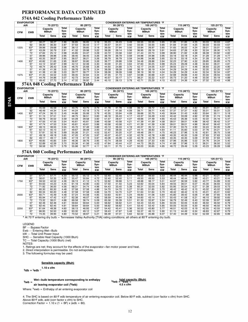
PERFORMANCE DATA CONTINUED574A 042 Cooling Performance Table
EVAPORATORAIR
CONDENSER ENTERING AIR TEMPERATURES °F75 (23°C) 85 (29°C) 95 (35°C) 105 (40°C) 115 (46°C) 125 (51°C)
CFM EWBCapacityMBtuh
TotalSys-temKW
CapacityMBtuh
TotalSys-temKW
CapacityMBtuh
TotalSys-temKW
CapacityMBtuh
TotalSys-temKW
CapacityMBtuh
TotalSys-temKW
CapacityMBtuh
TotalSys-temKWTotal Sens Total Sens Total Sens Total Sens Total Sens Total Sens
1225
57 38.27 38.27 2.86 36.85 36.85 3.16 35.23 35.23 3.49 33.55 33.55 3.85 31.85 31.85 4.25 30.03 30.03 4.6762 39.30 36.30 2.87 37.53 35.43 3.17 35.57 34.41 3.50 33.55 33.55 3.85 31.84 31.84 4.25 30.03 30.03 4.6763* 39.98 29.68 2.88 38.12 28.85 3.18 36.05 27.94 3.50 33.84 26.97 3.85 31.65 26.02 4.24 29.31 25.01 4.6567 43.26 30.79 2.91 41.32 29.98 3.22 39.26 29.14 3.56 36.95 28.19 3.91 34.63 27.26 4.30 32.24 26.30 4.7272 47.84 25.12 2.98 45.85 24.37 3.28 43.72 23.58 3.62 41.44 22.74 3.99 38.90 21.82 4.38 36.39 20.92 4.82
1400
57 39.96 39.96 2.95 38.45 38.45 3.26 36.79 36.79 3.59 34.98 34.98 3.95 33.18 33.18 4.34 31.29 31.29 4.7762 40.35 38.97 2.95 38.57 38.21 3.26 36.79 36.79 3.59 34.98 34.98 3.95 33.18 33.18 4.34 31.28 31.28 4.7763* 40.82 31.65 2.95 38.87 30.80 3.26 36.77 29.88 3.59 34.48 28.88 3.94 32.23 27.90 4.32 29.85 26.85 4.7367 44.12 32.87 2.99 42.12 32.06 3.30 40.00 31.20 3.64 37.63 30.25 3.99 35.24 29.28 4.38 32.84 28.31 4.8172 48.74 26.43 3.06 46.70 25.68 3.36 44.50 24.88 3.70 42.17 24.05 4.07 39.55 23.11 4.46 36.93 22.20 4.90
1575
57 41.38 41.38 3.03 39.78 39.78 3.34 38.09 38.09 3.68 36.19 36.19 4.04 34.29 34.29 4.44 32.35 32.35 4.8762 41.38 41.38 3.03 39.77 39.77 3.34 38.09 38.09 3.68 36.19 36.19 4.04 34.29 34.29 4.44 32.34 32.34 4.8763* 41.45 33.52 3.03 39.45 32.64 3.34 37.35 31.73 3.67 34.98 30.68 4.01 32.68 29.66 4.40 30.30 28.55 4.8267 44.76 34.86 3.07 42.73 34.04 3.38 40.57 33.17 3.71 38.21 32.22 4.07 35.73 31.20 4.46 33.30 30.19 4.8972 49.42 27.70 3.14 47.32 26.92 3.44 45.10 26.13 3.78 42.71 25.29 4.15 40.02 24.36 4.54 37.32 23.43 4.98
574A 048 Cooling Performance TableEVAPORATOR
AIRCONDENSER ENTERING AIR TEMPERATURES °F
75 (23°C) 85 (29°C) 95 (35°C) 105 (40°C) 115 (46°C) 125 (51°C)
CFM EWBCapacityMBtuh
TotalSys-temKW
CapacityMBtuh
TotalSys-temKW
CapacityMBtuh
TotalSys-temKW
CapacityMBtuh
TotalSys-temKW
CapacityMBtuh
TotalSys-temKW
CapacityMBtuh
TotalSys-temKWTotal Sens Total Sens Total Sens Total Sens Total Sens Total Sens
1400
57 45.59 45.59 3.42 43.75 43.75 3.74 41.78 41.78 4.08 39.72 39.72 4.45 37.38 37.38 4.82 35.01 35.01 5.2362 46.49 44.34 3.44 44.24 43.18 3.75 41.91 41.56 4.09 39.71 39.71 4.45 37.37 37.37 4.82 35.01 35.01 5.2363* 47.24 36.13 3.45 44.86 35.06 3.76 42.35 33.94 4.09 39.66 32.75 4.45 36.64 31.43 4.80 33.64 30.11 5.1867 51.15 37.51 3.51 48.75 36.51 3.83 46.16 35.43 4.17 43.37 34.29 4.53 40.42 33.09 4.92 37.09 31.74 5.3072 56.76 30.52 3.59 54.28 29.58 3.92 51.57 28.57 4.27 48.66 27.49 4.65 45.53 26.36 5.05 42.22 25.16 5.47
1600
57 47.55 47.55 3.54 45.61 45.61 3.86 43.58 43.58 4.21 41.39 41.39 4.58 39.01 39.01 4.96 36.42 36.42 5.3762 47.74 47.53 3.54 45.61 45.61 3.86 43.58 43.58 4.21 41.39 41.39 4.58 39.01 39.01 4.96 36.42 36.42 5.3763* 48.15 38.55 3.55 45.70 37.46 3.86 43.13 36.33 4.19 40.37 35.12 4.55 37.30 33.75 4.90 34.24 32.35 5.2967 52.12 40.10 3.61 49.67 39.09 3.93 47.00 38.00 4.27 44.14 36.83 4.64 41.11 35.60 5.03 37.76 34.21 5.4172 57.81 32.16 3.69 55.26 31.21 4.02 52.47 30.20 4.37 49.46 29.11 4.75 46.23 27.96 5.16 42.81 26.75 5.58
1800
57 49.18 49.18 3.65 47.20 47.20 3.97 45.07 45.07 4.32 42.78 42.78 4.69 40.35 40.35 5.09 37.63 37.63 5.5062 49.17 49.17 3.65 47.19 47.19 3.97 45.06 45.06 4.32 42.78 42.78 4.69 40.35 40.35 5.09 37.63 37.63 5.5063* 48.85 40.85 3.64 46.36 39.76 3.95 43.74 38.59 4.29 40.93 37.33 4.65 37.96 35.96 5.02 34.76 34.34 5.4067 52.89 42.59 3.70 50.36 41.56 4.02 47.64 40.44 4.37 44.73 39.25 4.74 41.66 37.96 5.13 38.31 36.50 5.5272 58.58 33.71 3.79 55.98 32.77 4.11 53.11 31.75 4.47 50.03 30.65 4.85 46.72 29.49 5.26 43.23 28.28 5.68
574A 060 Cooling Performance TableEVAPORATOR
AIRCONDENSER ENTERING AIR TEMPERATURES °F
75 (23°C) 85 (29°C) 95 (35°C) 105 (40°C) 115 (46°C) 125 (51°C)
CFM EWBCapacityMBtuh
TotalSys-temKW
CapacityMBtuh
TotalSys-temKW
CapacityMBtuh
TotalSys-temKW
CapacityMBtuh
TotalSys-temKW
CapacityMBtuh
TotalSys-temKW
CapacityMBtuh
TotalSys-temKWTotal Sens Total Sens Total Sens Total Sens Total Sens Total Sens
1750
57 57.71 57.71 4.33 55.12 55.12 4.71 52.40 52.40 5.11 49.50 49.50 5.53 46.44 46.44 5.98 43.21 43.21 6.4462 58.61 52.35 4.35 55.47 50.84 4.72 52.40 52.40 5.11 49.50 49.50 5.53 46.44 46.44 5.98 43.21 43.21 6.4463* 59.50 42.52 4.36 56.13 41.12 4.73 52.62 39.68 5.11 48.88 38.17 5.51 44.97 36.59 5.92 40.77 34.89 6.3367 64.63 44.23 4.45 61.18 42.90 4.83 57.50 41.50 5.23 53.62 40.04 5.64 49.55 38.51 6.07 45.30 36.93 6.5272 71.92 36.00 4.56 68.31 34.74 4.96 64.43 33.40 5.38 60.31 32.00 5.82 55.95 30.54 6.27 51.39 29.03 6.73
2000
57 60.30 60.30 4.48 57.58 57.58 4.86 54.70 54.70 5.27 51.65 51.65 5.70 48.42 48.42 6.15 45.02 45.02 6.6262 60.34 60.20 4.48 57.58 57.58 4.86 54.70 54.70 5.27 51.64 51.64 5.70 48.42 48.42 6.15 45.01 45.01 6.6263* 60.71 45.49 4.48 57.24 44.08 4.85 53.63 42.61 5.24 49.80 41.06 5.64 45.80 39.42 6.06 41.69 37.65 6.4967 65.94 47.42 4.57 62.38 46.07 4.95 58.59 44.64 5.36 54.60 43.14 5.77 50.43 41.58 6.21 46.10 39.92 6.6572 73.32 38.01 4.68 69.58 36.74 5.09 65.56 35.39 5.51 61.30 33.97 5.94 56.79 32.49 6.40 52.09 30.97 6.86
2250
57 62.46 62.46 4.61 59.64 59.64 5.00 56.62 56.62 5.41 53.43 53.43 5.85 50.05 50.05 6.30 46.50 46.50 6.7862 62.45 62.45 4.61 59.64 59.64 5.00 56.62 56.62 5.41 53.42 53.42 5.85 50.05 50.05 6.30 46.50 46.50 6.7863* 61.64 48.36 4.60 58.13 46.93 4.97 54.42 45.41 5.36 50.53 43.80 5.77 46.51 42.03 6.19 42.55 42.55 6.6367 66.95 50.50 4.69 63.30 49.12 5.07 59.43 47.67 5.48 55.37 46.13 5.90 51.15 44.49 6.34 46.83 42.67 6.7972 74.35 39.95 4.80 70.52 38.67 5.21 66.39 37.31 5.63 62.02 35.88 6.07 57.40 34.39 6.52 52.59 32.85 6.99
* At 75°F entering dry bulb --- Tennessee Valley Authority [TVA] rating conditions; all others at 80°F entering dry bulb.
LEGENDBF — Bypass FactorEwb — Entering Wet---BulbkW — Total Unit Power InputSHC — Sensible Heat Capacity (1000 Btuh)TC — Total Capacity (1000 Btuh) (net)NOTES:1. Ratings are net; they account for the effects of the evaporator ---fan motor power and heat.2. Direct interpolation is permissible. Do not extrapolate.3. The following formulas may be used:
Sensible capacity (Btuh)
1.10 x cfmtldb = tedb --
Wet---bulb temperature corresponding to enthalpy
air leaving evaporator coil (hlwb)tlwb =
total capacity (Btuh)
4.5 x cfmhlwb = hewb ---
Where: hewb = Enthalpy of air entering evaporator coil
4. The SHC is based on 80°F edb temperature of air entering evaporator coil. Below 80°F edb, subtract (corr factor x cfm) from SHC.Above 80°F edb, add (corr factor x cfm) to SHC.Correction Factor = 1.10 x (1 + BF) x (edb + 80).
574A

13
PERFORMANCE DATA CONTINUED
Dry Coil Air Delivery* -- Horizontal and Downflow Discharge -- Unit 574A018--060 (Deduct 10% for 208Volts)
UNITHEATINGRISE RANGE
OF
MOTORSPEED
EXTERNAL STATIC PRESSURE (IN. W.C.)
0.1 0.2 0.3 0.4 0.5 0.6 0.7 0.8 0.9
574A018040 30 --- 60
Low1WATTS 260 243 229 217 209 --- --- --- --- --- --- --- ---CFM 859 775 667 536 382 --- --- --- --- --- --- --- ---HEATING RISEOF 35 39 45 56 NA NA NA NA NA
High
WATTS 340 328 317 307 300 294 --- --- --- --- --- ---CFM 1064 948 820 680 528 364 --- --- --- --- --- ---HEATING RISEOF NA 32 37 44 57 NA NA NA NA
574A024040 20 --- 50
Low1WATTS 311 309 304 301 286 290 286 280 --- --- --- --- ---CFM 935 885 820 757 686 583 423 263 --- --- --- --- ---HEATING RISEOF 32 34 37 40 44 NA NA NA NA
Medium
WATTS 411 405 398 390 379 357 357 345 327CFM 1195 1155 1100 1028 957 868 769 647 365HEATING RISEOF 25 26 27 29 31 35 39 46 NA
High
WATTS 528 518 509 492 477 467 447 435 421CFM 1484 1421 1368 1279 1185 1088 970 853 712HEATING RISEOF 20 21 22 23 25 28 31 35 42
574A024060 35 --- 65
Low1WATTS 311 309 304 301 286 290 286 280 --- --- --- --- ---CFM 935 885 820 757 686 583 423 263 --- --- --- --- ---HEATING RISEOF 48 51 55 59 NA NA NA NA NA
Medium
WATTS 411 405 398 390 379 357 357 345 327CFM 1195 1155 1100 1028 957 868 769 647 365HEATING RISEOF 38 39 41 44 47 52 59 NA NA
High
WATTS 528 518 509 492 477 467 447 435 421CFM 1484 1421 1368 1279 1185 1088 970 853 712HEATING RISEOF NA NA NA 35 38 41 46 53 63
574A030040 20 --- 50
Low
WATTS 311 309 304 301 286 290 286 280 --- --- --- --- ---CFM 935 885 820 757 686 583 423 263 --- --- --- --- ---HEATING RISEOF 32 34 37 40 44 NA NA NA NA
Medium1WATTS 411 405 398 390 379 357 357 345 327CFM 1195 1155 1100 1028 957 868 769 647 365HEATING RISEOF 25 26 27 29 31 35 39 46 NA
High
WATTS 528 518 509 492 477 467 447 435 421CFM 1484 1421 1368 1279 1185 1088 970 853 712HEATING RISEOF 20 21 22 23 25 28 31 35 42
574A030060 35 --- 65
Low
WATTS 311 309 304 301 286 290 286 280 --- --- --- --- ---CFM 935 885 820 757 686 583 423 263 --- --- --- --- ---HEATING RISEOF 48 51 55 59 NA NA NA NA NA
Medium1WATTS 411 405 398 390 379 357 357 345 327CFM 1195 1155 1100 1028 957 868 769 647 365HEATING RISEOF 38 39 41 44 47 52 59 NA NA
High
WATTS 528 518 509 492 477 467 447 435 421CFM 1484 1421 1368 1279 1185 1088 970 853 712HEATING RISEOF NA NA NA 35 38 41 46 53 63
574A036060 25 --- 55
Low
WATTS 439 429 415 401 395 380 356 339 329CFM 1242 1170 1089 994 917 837 702 570 442HEATING RISEOF 36 38 41 45 49 54 NA NA NA
Medium1WATTS 503 491 479 461 450 436 418 404 389CFM 1320 1244 1162 1081 1005 897 767 662 541HEATING RISEOF 34 36 39 42 45 50 NA NA NA
High
WATTS 641 627 623 609 601 588 571 559 548CFM 1362 1288 1205 1119 1033 933 826 714 580HEATING RISEOF 33 35 37 40 44 48 54 NA NA
574A036090 40 --- 70
Low
WATTS 439 429 415 401 395 380 356 339 329CFM 1242 1170 1089 994 917 837 702 570 442HEATING RISEOF 54 58 62 68 NA NA NA NA NA
Medium1WATTS 503 491 479 461 450 436 418 404 389CFM 1320 1244 1162 1081 1005 897 767 662 541HEATING RISEOF 51 54 58 62 67 NA NA NA NA
High
WATTS 641 627 623 609 601 588 571 559 548CFM 1362 1288 1205 1119 1033 933 826 714 580HEATING RISEOF 50 52 56 60 65 NA NA NA NA
574A042060 25 --- 55
Low
WATTS 434 428 422 403 404 390 375 360 344CFM 1282 1241 1206 1160 1109 1040 967 890 813HEATING RISEOF 35 36 37 39 41 43 47 51 55
Medium1WATTS 560 548 535 526 511 496 478 460 439CFM 1526 1482 1437 1398 1344 1281 1205 1125 1029HEATING RISEOF 29 30 31 32 33 35 37 40 44
High
WATTS 765 746 730 709 690 664 642 624 600CFM 1860 1805 1751 1685 1620 1541 1468 1370 1265HEATING RISEOF NA 25 26 27 28 29 31 33 36
574A

14
PERFORMANCE DATA CONTINUEDDry Coil Air Delivery* -- Horizontal and Downflow Discharge -- Unit 574A018--060 (Deduct 10% for 208 Volts) (Cont)
UNITHEATINGRISE RANGE
OF
MOTORSPEED
EXTERNAL STATIC PRESSURE (IN. W.C.)
0.1 0.2 0.3 0.4 0.5 0.6 0.7 0.8 0.9
574A042090 40 --- 70
LowWatts 434 428 422 403 404 390 375 360 344CFM 1282 1241 1206 1160 1109 1040 967 890 813Heating Rise oF 53 54 56 58 61 65 70 NA NA
Medium1Watts 560 548 535 526 511 496 478 460 439CFM 1526 1482 1437 1398 1344 1281 1205 1125 1029Heating Rise oF 44 46 47 48 50 53 56 60 66
HighWatts 765 746 730 709 690 664 642 624 600CFM 1860 1805 1751 1685 1620 1541 1468 1370 1265Heating Rise oF NA NA NA 40 42 44 46 49 53
574A048090 25 --- 55
LowWatts 627 617 607 584 567 548 528 503 480CFM 1550 1530 1493 1461 1414 1361 1320 1250 1177Heating Rise oF 44 44 45 46 48 50 51 54 NA
Medium1Watts 771 755 734 711 690 665 639 607 572CFM 1798 1771 1734 1687 1645 1595 1530 1449 1355Heating Rise oF 38 38 39 40 41 42 44 47 50
HighWatts 969 941 908 887 858 827 804 767 748CFM 2124 2071 2000 1944 1876 1811 1735 1647 1555Heating Rise oF 32 33 34 35 36 37 39 41 43
574A048115 35 --- 65
LowWatts 627 617 607 584 567 548 528 503 480CFM 1550 1530 1493 1461 1414 1361 1320 1250 1177Heating Rise oF 56 56 58 59 61 63 65 NA NA
Medium1Watts 771 755 734 711 690 665 639 607 572CFM 1798 1771 1734 1687 1645 1595 1530 1449 1355Heating Rise oF 48 49 50 51 52 54 56 60 64
HighWatts 969 941 908 887 858 827 804 767 748CFM 2124 2071 2000 1944 1876 1811 1735 1647 1555Heating Rise oF 41 42 43 44 46 48 50 52 55
574A048130 40 --- 70
LowWatts 627 617 607 584 567 548 528 503 480CFM 1550 1530 1493 1461 1414 1361 1320 1250 1177Heating Rise oF 63 64 65 67 69 NA NA NA NA
Medium1Watts 771 755 734 711 690 665 639 607 572CFM 1798 1771 1734 1687 1645 1595 1530 1449 1355Heating Rise oF 54 55 56 58 59 61 64 67 NA
HighWatts 969 941 908 887 858 827 804 767 748CFM 2124 2071 2000 1944 1876 1811 1735 1647 1555Heating Rise oF 46 47 49 50 52 54 56 59 63
574A060090 25 --- 55
Low1Watts 786 769 754 736 722 705 684 658 616CFM 2027 1960 1901 1821 1759 1693 1616 1513 1354Heating Rise oF 33 34 36 37 38 40 42 45 50
MediumWatts 873 849 833 815 798 782 763 748 704CFM 2095 2026 1962 1887 1817 1748 1679 1583 1439Heating Rise oF 32 33 34 36 37 39 40 43 47
HighWatts 1012 993 981 963 948 927 904 886 846CFM 2184 2109 2036 1963 1886 1812 1729 1647 1496Heating Rise oF 31 32 33 34 36 37 39 41 45
574A060115 35 --- 65
Low1Watts 786 769 754 736 722 705 684 658 616CFM 2027 1960 1901 1821 1759 1693 1616 1513 1354Heating Rise oF 43 44 45 47 49 51 53 57 64
MediumWatts 873 849 833 815 798 782 763 748 704CFM 2095 2026 1962 1887 1817 1748 1679 1583 1439Heating Rise oF 41 43 44 46 47 49 51 54 60
HighWatts 1012 993 981 963 948 927 904 886 846CFM 2184 2109 2036 1963 1886 1812 1729 1647 1496Heating Rise oF 39 41 42 44 46 48 50 52 58
574A060130 40 --- 70
Low1Watts 786 769 754 736 722 705 684 658 616CFM 2027 1960 1901 1821 1759 1693 1616 1513 1354Heating Rise oF 48 50 51 54 55 58 60 64 NA
MediumWatts 873 849 833 815 798 782 763 748 704CFM 2095 2026 1962 1887 1817 1748 1679 1583 1439Heating Rise oF 47 48 50 52 54 56 58 62 68
HighWatts 1012 993 981 963 948 927 904 886 846CFM 2184 2109 2036 1963 1886 1812 1729 1647 1496Heating Rise oF 45 46 48 50 52 54 56 59 65
*Air delivery values are without air filter and are for dry coil (see Wet Coil Pressure Drop table).1Factory---shipped heating/cooling speed“NA” = Not allowed for heating speedNote: Deduct field---supplied air filter pressure drop and wet coil pressure drop to obtain external static pressure available for ducting.
574A
15
PERFORMANCE DATA (CONT)
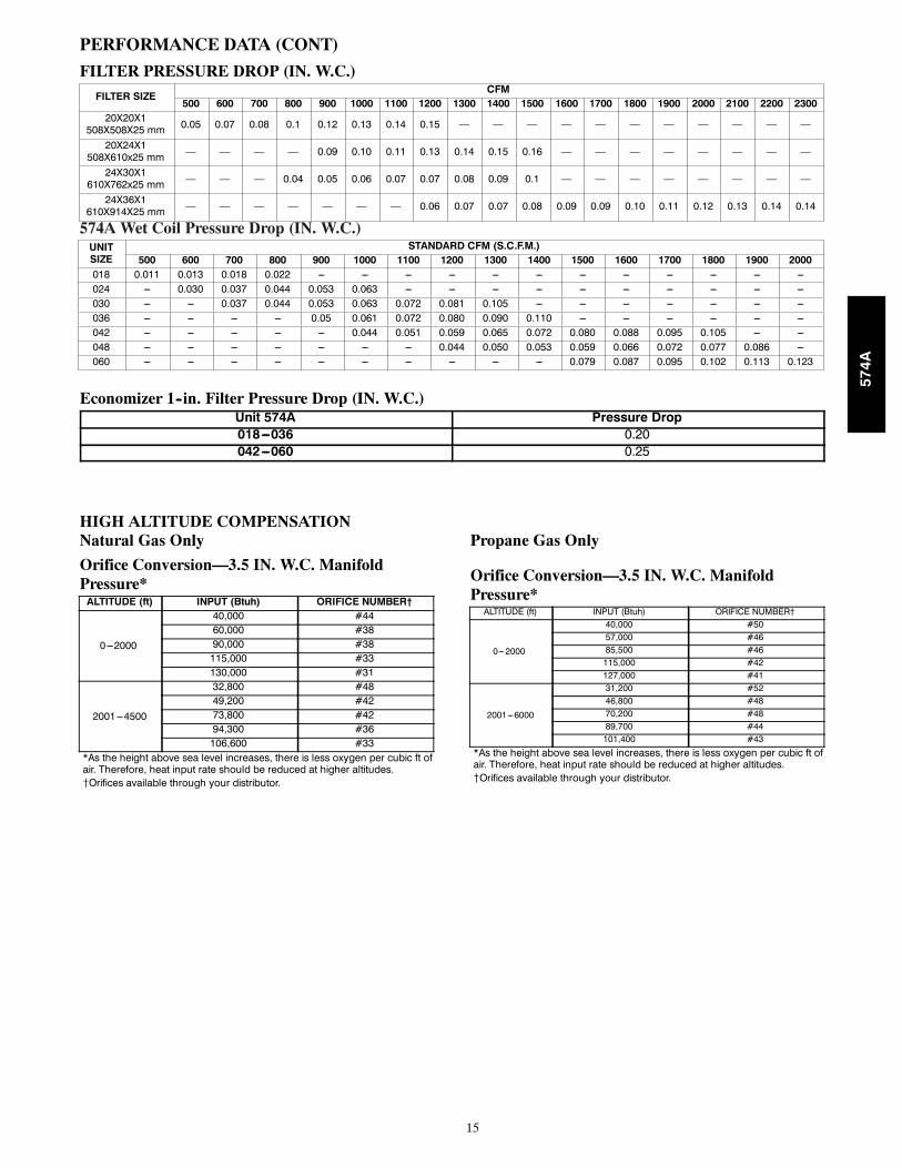
FILTER PRESSURE DROP (IN. W.C.)FILTER SIZE
CFM500 600 700 800 900 1000 1100 1200 1300 1400 1500 1600 1700 1800 1900 2000 2100 2200 2300
20X20X1508X508X25 mm 0.05 0.07 0.08 0.1 0.12 0.13 0.14 0.15 — — — — — — — — — — —
20X24X1508X610x25 mm — — — — 0.09 0.10 0.11 0.13 0.14 0.15 0.16 — — — — — — — —
24X30X1610X762x25 mm — — — 0.04 0.05 0.06 0.07 0.07 0.08 0.09 0.1 — — — — — — — —
24X36X1610X914X25 mm — — — — — — — 0.06 0.07 0.07 0.08 0.09 0.09 0.10 0.11 0.12 0.13 0.14 0.14
574A Wet Coil Pressure Drop (IN. W.C.)UNITSIZE
STANDARD CFM (S.C.F.M.)500 600 700 800 900 1000 1100 1200 1300 1400 1500 1600 1700 1800 1900 2000
018 0.011 0.013 0.018 0.022 --- --- --- --- --- --- --- --- --- --- --- ---024 --- 0.030 0.037 0.044 0.053 0.063 --- --- --- --- --- --- --- --- --- ---030 --- --- 0.037 0.044 0.053 0.063 0.072 0.081 0.105 --- --- --- --- --- --- ---036 --- --- --- --- 0.05 0.061 0.072 0.080 0.090 0.110 --- --- --- --- --- ---042 --- --- --- --- --- 0.044 0.051 0.059 0.065 0.072 0.080 0.088 0.095 0.105 --- ---048 --- --- --- --- --- --- --- 0.044 0.050 0.053 0.059 0.066 0.072 0.077 0.086 ---060 --- --- --- --- --- --- --- --- --- --- 0.079 0.087 0.095 0.102 0.113 0.123
Economizer 1--in. Filter Pressure Drop (IN. W.C.)Unit 574A Pressure Drop018---036 0.20042---060 0.25
HIGH ALTITUDE COMPENSATIONNatural Gas Only
Orifice Conversion—3.5 IN. W.C. ManifoldPressure*ALTITUDE (ft) INPUT (Btuh) ORIFICE NUMBER†
0---2000
40,000 #4460,000 #3890,000 #38115,000 #33130,000 #31
2001---4500
32,800 #4849,200 #4273,800 #4294,300 #36106,600 #33
*As the height above sea level increases, there is less oxygen per cubic ft ofair. Therefore, heat input rate should be reduced at higher altitudes.{Orifices available through your distributor.
Propane Gas Only
Orifice Conversion—3.5 IN. W.C. ManifoldPressure*ALTITUDE (ft) INPUT (Btuh) ORIFICE NUMBER†
0---2000
40,000 #5057,000 #4685,500 #46115,000 #42127,000 #41
2001---6000
31,200 #5246,800 #4870,200 #4889,700 #44101,400 #43
*As the height above sea level increases, there is less oxygen per cubic ft ofair. Therefore, heat input rate should be reduced at higher altitudes.{Orifices available through your distributor.
574A

16
TYPICAL PIPING AND WIRING
INDOORTHERMOSTAT
DISCONNECTPER NEC*
FROMPOWERSOURCE
RETURNAIR
TOP COVER
FROMGAS LINE
ROOF
RETURN-AIRFLEXIBLE DUCT
CEILINGCONCENTRIC DIFFUSER BOX(FIELD-SUPPLIED)
SUPPLY-AIRFLEXIBLE DUCT
ROOF-MOUNTINGCURB
*NEC - NATIONAL ELECTRICAL CODE
VERTICAL DISCHARGE
574A

17
APPLICATION DATACondensate trap — A 2--in. (50.8 mm) condensate trap must befield supplied.
Ductwork — Secure downflow discharge ductwork to roof curb.For horizontal discharge applications, attach ductwork to unit withflanges.
To convert a unit to downflow discharge — Units are equippedwith factory--installed inserts in the down--flow openings. Removalof the inserts is similar to removing an electrical knock--out. Usethe duct cover to seal the horizontal discharge openings in the unit.Units installed in horizontal discharge orientation do not requireduct covers.
Airflow — Units are draw--thru in the cooling mode andblow--thru in the heating mode.
Maximum cooling airflow — To minimize the possibility ofcondensate blow--off from the evaporator, airflow through the unitsshould not exceed 450 cfm per ton.
Minimum cooling airflow — Minimum cooling airflow is 350cfm per ton.
Minimum ambient cooling operation temperature — Allstandard units have a minimum ambient operating temperature of40_F (4_C). With accessory low ambient temperature kit, units canoperate at temperatures down to 0_F (--17_C).
Minimum temperature — Air entering the heat exchanger inheating mode must be a minimum of 50_F (10_C) continuousand/or 45_F (7_C) intermittent.
574A

18
ELECTRICAL DATAUNIT NOMINAL
V---PH---HZVOLTAGE RANGE COMPRESSOR #1 OFM IFM POWER SUPPLY
MCA MOCPMIN MAX RLA LRA FLA FLA574A---018 208/230---1---60 187 253 7.7 40.3 0.9 1.8 12.3 20574A---024 208/230---1---60 187 253 10.4 54.0 0.9 2.0 15.9 25
574A---030208/230---1---60 187 253 14.1 68.0 0.9 2.0 20.5 30208/230---3---60 187 253 9.9 58.0 0.9 2.0 15.3 25
574A---036
208/230---1---60 187 253 14.4 77.0 0.9 4.1 23.0 35208/230---3---60 187 253 10.0 73.0 0.9 4.1 17.5 25460---3---60 414 506 5.8 38.0 0.6 1.9 9.8 15
574A---042
208/230---1---60 187 253 19.2 104.0 0.9 3.1 28.0 40208/230---3---60 187 253 12.8 88.0 0.9 3.1 20.0 30460---3---60 414 506 5.8 44.0 0.6 1.6 9.5 15
574A---048
208/230---1---60 187 253 19.2 97.0 1.5 4.1 29.6 40208/230---3---60 187 253 12.5 88.0 1.5 4.1 21.2 30460---3---60 414 506 6.6 44.0 0.9 1.9 11.1 15
574A---060
208/230---1---60 187 253 25.3 141.0 1.5 6.2 39.3 60208/230---3---60 187 253 15.8 110.0 1.5 6.2 27.5 40460---3---60 414 506 7.6 52.0 0.9 2.7 13.1 20
228 = 1 v229 = 2 v227 = 2 v
LEGEND
FLA — Full Load AmpsLRA — Locked Rotor AmpsMCA -- Minimum Circuit AmpsMOCP — Maximum Overcurrent ProtectionRLA — Rated Load Amps
NO TES:1. In compliance with NEC (National Electrical Code) requirements
for multimotor and combination load equipment (refer to NE CArticles 430 and 440), the overcurrent protective device for theunit shall be Power Supply fuse. The CGA (Canadian GasAssociation) units may be fuse or circuit break er.
2. Minimum wire size is based on 60 C copper wire. I f other than60 C wire is used, or if length exceeds wire length in table,determine siz e from NEC..
3. Unbalanced 3-Phase Supply VoltageNever operate a motor where a phase imbalance in supply volt-age is greater than 2%. Use the following formula to determinethe percentage of voltage imbalance.
% Voltage imbalance
max voltage deviation from average voltage= 100 xaverage voltage
EXAMPLE: Supply voltage is 230-3-60.AB = 228 vBC = 231 vAC = 227 v
228 + 231 + 227Average Voltage =3
686=3
= 229
Determine maximum deviation from average voltage.(AB) 229 -(BC) 231 -(AC) 229 -
Maximum deviation is 2 v.
Determine percent of voltage imbalance.2% Voltage Imbalance = 100 x
229
= 0.8%
This amount of phase imbalance is satisfactory as it is below themaximum allowable 2%.
IMPORTANT: If the supply voltage phase imbalance ismore than 2%, contact your local electric utility companyimmediately.
®
*Heater capacity (kW) based on heater voltage of 208v & 240v.If power distibution voltage to unit varies from rated heater voltage, heater kW will vary accordingly.
574A
19
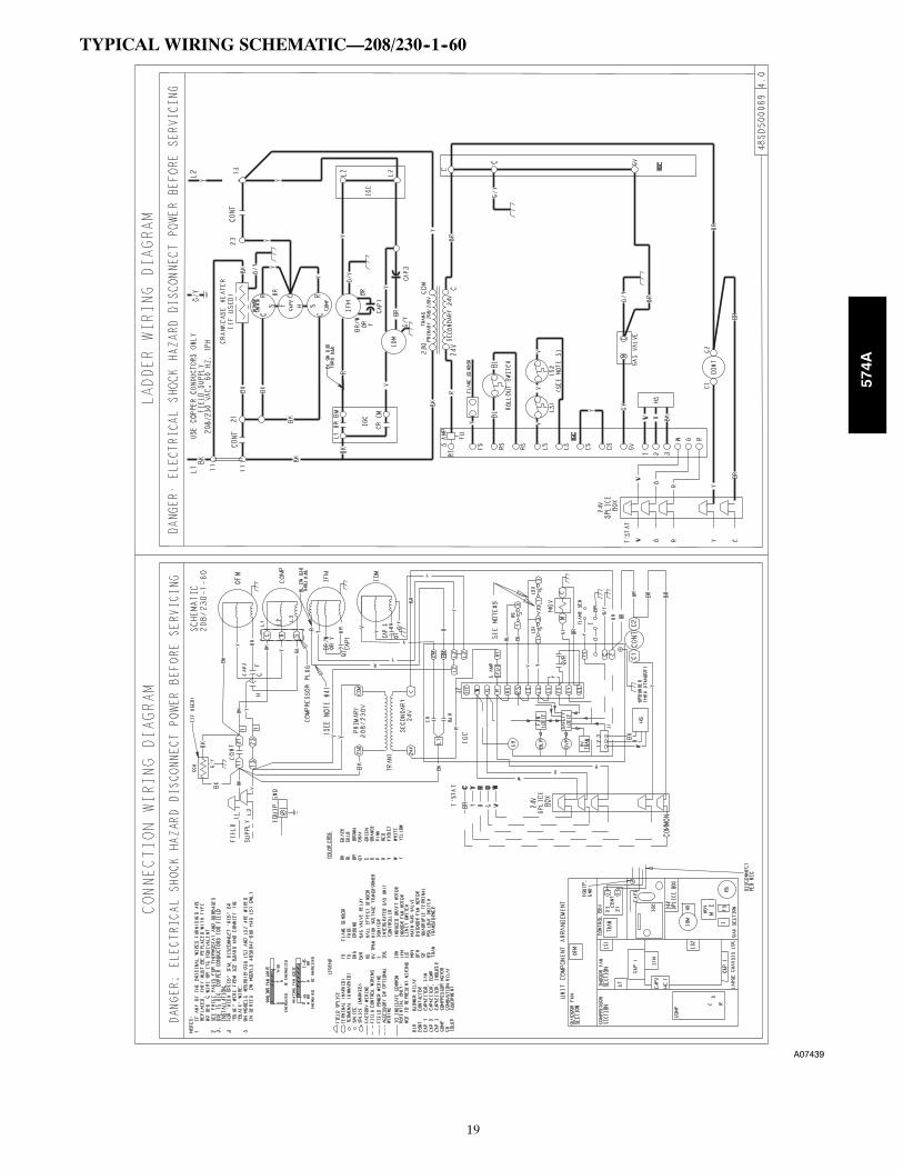
TYPICAL WIRING SCHEMATIC—208/230--1--60
A07439
574A

20
TYPICAL WIRING SCHEMATIC—208/230--3--60
A07569
574A

21
TYPICAL WIRING SCHEMATIC—460--3--60
A07570
574A

22
CONTROLSOperating sequenceHeating — When the thermostat calls for heating, terminal “W” isenergized, starting the induced draft motor. When the hall--effectsensor on the induced--draft motor senses that it has reached therequired speed, the burner ignition sequence begins. The indoor(evaporator) fan motor (IFM) is energized 45 seconds after flame isestablished. When the thermostat is satisfied and “W” isde--energized, the IFM stops after a 45--second time--off delay.Please note that the ignition control board (IGC) has the capabilityto automatically reduce the indoor fan motor on and off delays inthe event of high duct static and/or partially--clogged filter. Anadjustment of fan delays by the ignition control board is indicatedby a flash code “1” on the LED on the IGC.
Cooling — When the system thermostat calls for cooling, 24 V issupplied to the “Y“ and “G“ terminals of the thermostat. Thiscompletes the circuit to the contactor coil (C) and indoor(evaporator) fan relay (IFR). The normally open contacts ofenergized C close and complete the circuit through compressormotor (COMP) to outdoor (condenser) fan motor (OFM). Bothmotors start instantly. The set of normally open contacts ofenergized IFR close and complete the circuit through IFM. TheIFM starts instantly.
On the loss of the thermostat call for cooling, 24 V is removedfrom both the “Y” and “G“ terminals (provided the fan switch is inthe “AUTO“ position) de--energizing the compressor contactor andopening the contacts supplying power to compressor/OFM. After a30--second delay, the IFM shuts off. If the thermostat fan selectorswitch is in the “ON“ position, the IFM will run continuously.
NOTE: On units with a Time Guard® II device: Once thecompressor has started and then stopped, it cannot be restartedagain until 5 minutes have elapsed.
574A
23
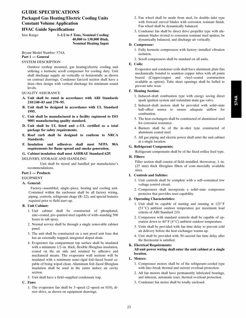
GUIDE SPECIFICATIONSPackaged Gas Heating/Electric Cooling UnitsConstant Volume ApplicationHVAC Guide SpecificationsSize Range: 1--1/2 to 5 Tons, Nominal Cooling
40,000 to 130,000 Btuh,Nominal Heating Input
Bryant Model Number: 574APart 1 — GeneralSYSTEM DESCRIPTION
Outdoor rooftop mounted, gas heating/electric cooling unitutilizing a hermetic scroll compressor for cooling duty. Unitshall discharge supply air vertically or horizontally as shownon contract drawings. Condenser fan/coil section shall have adraw--thru design with vertical discharge for minimum soundlevels.
QUALITY ASSURANCE
A. Unit shall be rated in accordance with ARI Standards210/240--03 and 270--95.
B. Unit shall be designed in accordance with UL Standard1995.
C. Unit shall be manufactured in a facility registered to ISO9001 manufacturing quality standard.
D. Unit shall be UL listed and c--UL certified as a totalpackage for safety requirements.
E. Roof curb shall be designed to conform to NRCAStandards.
F. Insulation and adhesives shall meet NFPA 90Arequirements for flame spread and smoke generation.
G. Cabinet insulation shall meet ASHRAE Standard 62P.DELIVERY, STORAGE AND HANDLING
Unit shall be stored and handled per manufacturer’srecommendations.
Part 2 — ProductsEQUIPMENT
A. General:Factory--assembled, single--piece, heating and cooling unit.Contained within the enclosure shall be all factory wiring,piping, controls, refrigerant chage (R--22), and special featuresrequired prior to field start--up.
B. Unit Cabinet:1. Unit cabinet shall be constructed of phosphated,zinc--coated, pre--painted steel capable of with--standing 500hours in salt spray.
2. Normal service shall be through a single removable cabinetpanel.
3. The unit shall be constructed on a rust proof unit base thathas an externally trapped, integrated sloped drain.
4. Evaporator fan compartment top surface shall be insulatedwith a minimum 1/2--in. thick, flexible fiberglass insulation,coated on the air side and retained by adhesive andmechanical means. The evaporator wall sections will beinsulated with a minimum semi--rigid foil--faced board ca-pable of being wiped clean. Aluminum foil--faced fiberglassinsulation shall be used in the entire indoor air cavitysection.
5. Unit shall have a field--supplied condensate trap.
C. Fans:1. The evaporator fan shall be 3--speed (2--speed on 018), di-rect--drive, as shown on equipment drawings.
2. Fan wheel shall be made from steel, be double--inlet typewith forward curved blades with corrosion resistant finish.Fan wheel shall be dynamically balanced.
3. Condenser fan shall be direct drive propeller type with alu-minum blades riveted to corrosion resistant steel spiders, bedynamically balanced, and discharge air vertically.
D. Compressor:1. Fully hermetic compressors with factory--installed vibrationisolation.
2. Scroll compressors shall be standard on all units.
E. Coils:Evaporator and condenser coils shall have aluminum plate finsmechanically bonded to seamless copper tubes with all jointsbrazed (Copper/copper and vinyl--coated constructionavailable as option). Tube sheet openings shall be belled toprevent tube wear.
F. Heating Section:1. Induced--draft combustion type with energy saving directspark ignition system and redundant main gas valve.
2. Induced--draft motors shall be provided with solid--statehall--effect sensor to ensure adequate airflow forcombustion.
3. The heat exchangers shall be constructed of aluminized steelfor corrosion resistance.
4. Burners shall be of the in--shot type constructed ofaluminum coated steel.
5. All gas piping and electric power shall enter the unit cabinetat a single location.
G. Refrigerant Components:Refrigerant components shall be of the fixed orifice feed type.
H. Filters:Filter section shall consist of field--installed, throwaway, 1--in.(25 mm) thick fiberglass filters of com--mercially availablesizes.
I. Controls and Safeties:1. Unit controls shall be complete with a self--contained lowvoltage control circuit.
2. Compressors shall incorporate a solid--state compressorprotector that provides reset capability.
J. Operating Characteristics:1. Unit shall be capable of starting and running at 125_F(51_C) ambient outdoor temperature per maximum loadcriteria of ARI Standard 210.
2. Compressor with standard controls shall be capable of op-eration down to 40_F (4_C) ambient outdoor temperature.
3. Units shall be provided with fan time delay to prevent coldair delivery before the heat exchanger warms up.
4. Unit shall be provided with 30--second fan time delay afterthe thermostat is satisfied.
K. Electrical Requirements:All unit power wiring shall enter the unit cabinet at a singlelocation.
L. Motors:1. Compressor motors shall be of the refrigerant--cooled typewith line--break thermal and current overload protection.
2. All fan motors shall have permanently lubricated bearings,and inherent, automatic reset, thermal overload protection.
3. Condenser fan motor shall be totally enclosed.
574A
24
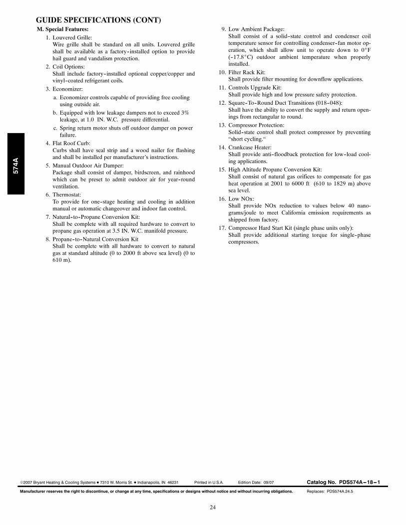
GUIDE SPECIFICATIONS (CONT)M. Special Features:
1. Louvered Grille:Wire grille shall be standard on all units. Louvered grilleshall be available as a factory--installed option to providehail guard and vandalism protection.
2. Coil Options:Shall include factory--installed optional copper/copper andvinyl--coated refrigerant coils.
3. Economizer:
a. Economizer controls capable of providing free coolingusing outside air.
b. Equipped with low leakage dampers not to exceed 3%leakage, at 1.0 IN. W.C. pressure differential.
c. Spring return motor shuts off outdoor damper on powerfailure.
4. Flat Roof Curb:Curbs shall have seal strip and a wood nailer for flashingand shall be installed per manufacturer’s instructions.
5. Manual Outdoor Air Damper:Package shall consist of damper, birdscreen, and rainhoodwhich can be preset to admit outdoor air for year--roundventilation.
6. Thermostat:To provide for one--stage heating and cooling in additionmanual or automatic changeover and indoor fan control.
7. Natural--to--Propane Conversion Kit:Shall be complete with all required hardware to convert topropane gas operation at 3.5 IN. W.C. manifold pressure.
8. Propane--to--Natural Conversion KitShall be complete with all hardware to convert to naturalgas at standard altitude (0 to 2000 ft above sea level) (0 to610 m).
9. Low Ambient Package:Shall consist of a solid--state control and condenser coiltemperature sensor for controlling condenser--fan motor op-eration, which shall allow unit to operate down to 0_F(--17.8_C) outdoor ambient temperature when properlyinstalled.
10. Filter Rack Kit:Shall provide filter mounting for downflow applications.
11. Controls Upgrade Kit:Shall provide high and low pressure safety protection.
12. Square--To--Round Duct Transitions (018--048):Shall have the ability to convert the supply and return open-ings from rectangular to round.
13. Compressor Protection:Solid--state control shall protect compressor by preventing“short cycling.“
14. Crankcase Heater:Shall provide anti--floodback protection for low--load cool-ing applications.
15. High Altitude Propane Conversion Kit:Shall consist of natural gas orifices to compensate for gasheat operation at 2001 to 6000 ft (610 to 1829 m) abovesea level.
16. Low NOx:Shall provide NOx reduction to values below 40 nano-grams/joule to meet California emission requirements asshipped from factory.
17. Compressor Hard Start Kit (single phase units only):Shall provide additional starting torque for single--phasecompressors.
Manufacturer reserves the right to discontinue, or change at any time, specifications or designs without notice and without incurring obligations.
E2007 Bryant Heating & Cooling Systems D 7310 W. Morris St. D Indianapolis, IN 46231 Printed in U.S.A. Edition Date: 09/07
Replaces: PDS574A.24.5
Catalog No. PDS574A---18---1
574A