product datadms.hvacpartners.com/docs/1009/public/0e/48es-1pd.pdf · product data a99338 unit 48es...
TRANSCRIPT

1
48ESSingle--Packaged Gas Heating/Electric Cooling Units with PuronR(R--410A) Refrigerant Single-- And Three--Phase Units1--1/2 to 5 Nominal Tons (Sizes 018--060)
Product Data
A99338
Unit 48ES
Single--Packaged Products with Energy--Saving Features and Pu-ronR refrigerant.
S 13 SEERS Up to 81% AFUES Factory--Installed TXV
S Multi--Speed Blower--StandardS Direct Spark Ignition
S Low Sound Levels
FEATURES/BENEFITSOne--piece heating and cooling units with low sound levels, easyinstallation, low maintenance, and dependable performance.Puron Environmentally Sound Refrigerant is Carrier’s uniquerefrigerant designed to help protect the environment. Puron is anHFC refrigerant which does not contain chlorine that can harm theozone layer. The most important advantage of Puron refrigerant isthat it has not been banned in future air conditioning systems as thetraditional refrigerant R--22 has been. Puron refrigerant is in servicein over 100,000 systems proving highly reliable, environmentallysound performance.Easy InstallationFactory--assembled package is a compact, fully self--contained,combination gas heating/electric cooling unit that is prewired, pre--piped, and pre--charged for minimum installation expense. Theseunits are available in a variety of standard and optional heating/cooling size combinations with voltage options to meet residentialand light commercial requirements.Units are lightweight and installeasily on a rooftop or at ground level. The high tech composite baseeliminates rust problems associated with ground level applications.Convertible duct configurationUnit is designed for easy use in either downflow or horizontal ap-plications. Each unit is easily converted from horizontal to down-flow with the two standard duct covers.
EfficientoperationHigh--efficiencydesign offers SEER (Season-al Energy Efficiency Ratios) of 13.0, and AFUE (Annual Fuel Uti-lization Efficiency) ratings as high as 81%.
Energy--saving, direct spark ignition saves gas by operating onlywhen the room thermostat calls for heating. Standard units are fur-nished with natural gas controls. A low--cost field installed kit forpropane conversion is available for all units.48ESN units are dedicated LowNOx units designed for Califor-nia installations. These models meet the California maximum ox-ides of nitrogen (NOx) emissions requirement of 40 nanograms/joule or less as shipped from the factory and MUST be installed inCalifornia Air Quality Management Districts where a Low NOxrule exists. LowNOx option is available on single phasemodelson-ly.
Durable, dependable componentsCompressors are designed forhigh efficiency.Each compressor is hermetically sealed against con-tamination to help promote longer life and dependable operation.Each compressor also has vibration isolation to provide quieter op-eration. All compressors have internal high pressure and overcur-rent protection.Monoport inshot burners produce precise air--to--gas mixture,which provides for clean and efficient combustion.The largemono-port on the inshot (or injection type) burners seldom, if ever, re-quires cleaning. All gas furnace components are accessible in onecompartment.Turbo--tubulart heat exchangers are constructed of aluminizedsteel for corrosion resistance and optimum heat transfer for im-proved efficiency. The tubular design permits hot gases to makemultiple passes across the path of the supply air.

2
In addition, dimples located on the heat exchanger walls force thehot gases to stay in close contact with the walls, improving heattransfer.
Direct--drive multi--speed blower motor is standard on all 48ESmodels.Direct--drive PSC condenser--fan motors are designed to help re-duce energy consumption and provide for cooing operation downto 40_F (4.4_C) outdoor temperature. Motormasterr II low ambi-ent kit is available as a field--installed accessory.Thermostat controlsTimeGuardr II anti--short cycle protection circuitry. If a non--cor-porate thermostat without anti--short cycle protection is used theTime Guard II field--installed anti--short cycle kit is recommended.
Thermostatic Expansion Valve -- A hard shutoff, balance portTXVmaintains a constant superheat at the evaporator exit (coolingcycle) resulting in higher overall system efficiency.
Refrigerant system is designed to provide dependability. Liquidfilter driers are used to promote clean, unrestricted operation. Eachunit leaves the factory with a full refrigerant charge. Refrigerant ser-vice connections make checking operating pressures easier.
High and Low Pressure Switches provide added reliability for thecompressor.Indoor and Outdoor coils are computer--designed for optimumheat transfer and efficiency. The indoor coil is fabricated from cop-per tube and aluminum fins and is located inside the unit for protec-tion against damage. The outdoor coil is internally mounted on thetop tier of the unit. Copper fin coils and pre--coated fin coils areavailable from the factory by special order. These coils are recom-mended in applications where aluminum fins are likely to be dam-aged due to corrosion. They are ideal for seacoast applications.
Lowsound ratingsensure aquiet indoorand outdoorenvironmentwith sound ratings as low as 72dBA.Easy to service cabinets provide easy single--panel accessibility toserviceable components during maintenance and installation. Thebasepanwith integrated drain pan provides easy ground level instal-lation with or without a mounting pad. Convenient handholds areprovided to manipulate the unit on the jobsite. A nesting feature en-sures a positive basepan to roof curb seal when the unit is roofmounted. A convenient 3/4--in. wide perimeter flange makes framemounting on a rooftop easy.Standard metal duct covers with insulation come with the unitand cover the horizontal duct openings. These can be left in place ifthe units are converted to downflow.
Integrated Gas Control (IGC) board provides safe and efficientcontrolofheating and simplifies trouble--shooting through itsbuilt--in diagnostic function.
Cabinets are constructed of heavyduty, phosphated, zinc--coatedprepainted steel capable of withstanding 500 hours in salt spray. In-terior surfaces of the evaporator/heat exchanger compartment areinsulated with cleanable semi--rigid insulation board, which keepsthe conditioned air from being affected by the outdoor ambienttemperature and provides improved indoor air quality. (Conformsto American Society of Heating, Refrigeration and Air Condition-ing Engineers No. 62P.) The sloped drain pan minimizes standingwater in the drain. An external drain is provided.
Downflow operation is easily provided in the field to allowverticalductwork connections. The basepan utilizes knockout style seals onthe bottom openings to ensure a positive seal in the horizontal air-flow mode.
TABLE OF CONTENTSFeatures/Benefits 1---2. . . . . . . . . . . . . . . . . . . . . . . . . . . . . . .
Model Number Nomenclature 3. . . . . . . . . . . . . . . . . . . . . . .
ARI Capacities 4. . . . . . . . . . . . . . . . . . . . . . . . . . . . . . . . . . . .
Physical Data 5. . . . . . . . . . . . . . . . . . . . . . . . . . . . . . . . . . . . .
Options and Accessories 6. . . . . . . . . . . . . . . . . . . . . . . . . . . .
Base Unit Dimensions 8---9. . . . . . . . . . . . . . . . . . . . . . . . . . .
Accessory Dimensions 10. . . . . . . . . . . . . . . . . . . . . . . . . . . .
Selection Procedure 11. . . . . . . . . . . . . . . . . . . . . . . . . . . . . . .
Performance Data 12---18. . . . . . . . . . . . . . . . . . . . . . . . . . . . .
Typical Piping and Wiring 19. . . . . . . . . . . . . . . . . . . . . . . . . .
Application Data 20. . . . . . . . . . . . . . . . . . . . . . . . . . . . . . . . . .
Electrical Data 21. . . . . . . . . . . . . . . . . . . . . . . . . . . . . . . . . . . .
Typical Wiring Schematics 22---24. . . . . . . . . . . . . . . . . . . . .
Controls 25. . . . . . . . . . . . . . . . . . . . . . . . . . . . . . . . . . . . . . . . .
Guide Specifications 26---27. . . . . . . . . . . . . . . . . . . . . . . . . .
48ES

3
MODEL NUMBER NOMENCLATURE
48ES --- ---040 1
Type of Unit48ES --- Single Packaged
Gas Heating/ElectricCooling Unit
Nominal Cooling Capacity018 --- 1---1/2 Tons024 --- 2.0 Tons030 --- 2.5 Tons036 --- 3.0 Tons042 --- 3.5 Tons048 --- 4.0 Tons060 --- 5.0 Tons
018
Heat Input Size (Btuh)040 --- 40,000060 --- 60,000090 --- 90,000115 --- 115,000130 --- 130,000
Electrical Supply3 --- 208/230---1---605 --- 208/230---3---60
3 0
Series
Packaging
Options
AD --- Louvered GrilleBT --- AL evap, vinyl condenserCC --- AL evap, CU condenserCU --- CU evap & condenserGS --- Stainless Steel HXTP --- Base unit with tin plated indoor coil hairpinsTV --- TP with vinyl coating on outdoor coilTC --- TP with AL indoor coil & CU/CU outdoor coil
See Price Page for full list of factory options.Only used if ordering an option
LEGENDAL --- AluminumCU --- Copper
---
Low NOx Indicator--- StandardN Low Nox
REGISTERED
ISO 9001:2000
48ES
4
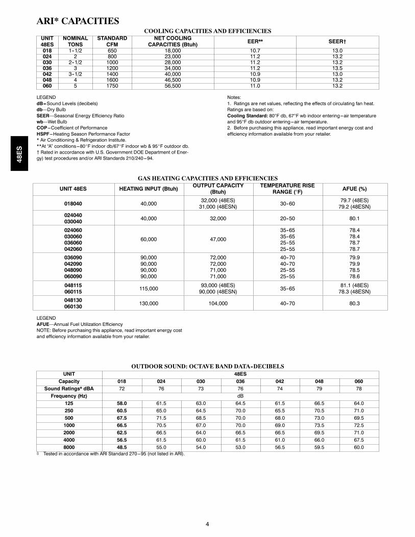
ARI* CAPACITIESCOOLING CAPACITIES AND EFFICIENCIES
UNIT48ES
NOMINALTONS
STANDARDCFM
NET COOLINGCAPACITIES (Btuh) EER** SEER†
018 1--1/2 650 18,000 10.7 13.0024 2 800 23,000 11.2 13.2030 2--1/2 1000 28,000 11.2 13.2036 3 1200 34,000 11.2 13.5042 3--1/2 1400 40,000 10.9 13.0048 4 1600 46,500 10.9 13.2060 5 1750 56,500 11.0 13.2
LEGENDdB---Sound Levels (decibels)db—Dry BulbSEER—Seasonal Energy Efficiency Ratiowb—Wet BulbCOP---Coefficient of PerformanceHSPF---Heating Season Performance Factor* Air Conditioning & Refrigeration Institute.**At “A” conditions---80_F indoor db/67_F indoor wb & 95_F outdoor db.{ Rated in accordance with U.S. Government DOE Department of Ener-gy) test procedures and/or ARI Standards 210/240---94.
Notes:1. Ratings are net values, reflecting the effects of circulating fan heat.Ratings are based on:Cooling Standard: 80°F db, 67°F wb indoor entering---air temperatureand 95°F db outdoor entering---air temperature.2. Before purchasing this appliance, read important energy cost andefficiency information available from your retailer.
GAS HEATING CAPACITIES AND EFFICIENCIES
UNIT 48ES HEATING INPUT (Btuh)OUTPUT CAPACITY
(Btuh)TEMPERATURE RISE
RANGE (°F) AFUE (%)
018040 40,00032,000 (48ES)
31,000 (48ESN) 30--6079.7 (48ES)
79.2 (48ESN)
024040030040 40,000 32,000 20--50 80.1
024060030060036060042060
60,000 47,000
35--6535--6525--5525--55
78.478.478.778.7
036090042090048090060090
90,00090,00090,00090,000
72,00072,00071,00071,000
40--7040--7025--5525--55
79.979.978.578.6
048115060115 115,000
93,000 (48ES)90,000 (48ESN) 35--65
81.1 (48ES)78.3 (48ESN)
048130060130 130,000 104,000 40--70 80.3
LEGENDAFUE—Annual Fuel Utilization EfficiencyNOTE: Before purchasing this appliance, read important energy costand efficiency information available from your retailer.
OUTDOOR SOUND: OCTAVE BAND DATA--DECIBELSUNIT 48ES
Capacity 018 024 030 036 042 048 060Sound Ratings* dBA 72 76 73 76 74 79 78
Frequency (Hz) dB
125 58.0 61.5 63.0 64.5 61.5 66.5 64.0
250 60.5 65.0 64.5 70.0 65.5 70.5 71.0
500 67.5 71.5 68.5 70.0 68.0 73.0 69.5
1000 66.5 70.5 67.0 70.0 69.0 73.5 72.5
2000 62.5 66.5 64.0 66.5 66.5 69.5 71.0
4000 56.5 61.5 60.0 61.5 61.0 66.0 67.5
8000 48.5 55.0 54.0 53.0 56.5 59.5 60.0* Tested in accordance with ARI Standard 270---95 (not listed in ARI).
48ES

5
PHYSICAL DATAUNIT SIZE 018040 024040 024060 030040 030060 036060 036090 042060 042090NOMINAL CAPACITY (ton) 1---1/2 2 2 2---1/2 2---1/2 3 3 3---1/2 3---1/2OPERATING WEIGHT lb.OPERATING WEIGHT (kg)
282127.9
296134.2
296134.2
313142.0
313142.0
338153.3
338153.3
401181.9
401181.9
COMPRESSORSQuantity
Scroll1
REFRIGERANT (R---410A)Quantity (lb.)Quantity (kg)
5.02.3
6.93.1
6.93.1
8.03.6
8.03.6
9.24.2
9.24.2
8.84.0
8.84.0
REFRIGERANT METERING DEVICE TXVCONDENSER COILRows...Fins/in.Face Area (sq ft)
1...2110.2
2...2110.2
2...2110.2
2...2111.9
2...2111.9
2...2113.6
2...2113.6
2...2115.5
2...2119.4
CONDENSER FANNominal CfmDiameter (in.)Diameter (mm)Motor Hp (Rpm)
220022558.81/8 (825)
220022558.81/8 (825)
220022558.81/8 (825)
280022558.81/8 (825)
280022558.81/8 (825)
300022558.81/8 (825)
300022558.81/8 (825)
350022558.81/8 (825)
350022558.81/8 (825)
EVAPORATOR COILRows...Fins/in.Face Area (sq ft)
3...173.7
3...173.7
3...173.7
3...173.7
3...173.7
4...173.7
4...173.7
3...174.7
3...174.7
INDOOR BLOWERNominal Airflow (Cfm)Size (in.)Size (mm.)Motor HP (RPM)
6 0 800 800 1000 1000 1200 1200 1 00 1 0065010x10254x2541/4 (825)
80010x10254x2541/3 (1050)
80010x10254x2541/3 (1050)
100010x10254x2541/3 (1050)
100010x10254x2541/3 (1050)
120010x10254x2541/2 (1000)
120010x10254x2541/2 (1000)
140011x10279.4x2541/2 (1075)
140011x10279.4x2541/2 (1075)
FURNACE SECTION*Burner Orifice No. (Qty...Drill Size)Natural GasPropane Gas
2...442...50
2...442...50
2...382...46
2...442...50
2...382...46
2...382...46
3...383...46
2...382...46
2...382...46
HIGH--PRESSURE SWITCH(psig) Cut--out Reset (Auto)
650 +/-- 15420 +/-- 25
LOSS--OF--CHARGE / LOW--PRES-SURE SWITCH (Liquid Line) (psig)cut--out Reset (auto)
20 +/-- 545 +/-- 10
RETURN---AIR FILTERS†}Throwaway Size (in.)
20x24x1508x610x25 (mm)
24x30x1610x762x25 (mm)
24x36x1610x914x25 (mm)
UNIT SIZE 048090 048115 048130 060090 060115 060130NOMINAL CAPACITY (ton) 4 4 4 5 5 5
OPERATING WEIGHT lbOPERATING WEIGHT kg
418189.6
418189.6
418189.6
446202.3
446202.3
446202.3
COMPRESSORSQuantity
Scroll1
REFRIGERANT (R--410A)Quantity (lb.)Quantity (kg.)
9.04.1
9.04.1
9.04.1
10.54.8
10.54.8
10.54.8
REFRIGERANT METERING DEVICE TXV
CONDENSER COILRows...Fins/in.Face Area (sq ft)
2...2119.4
2...2119.4
2...2119.4
2...2119.4
2...2119.4
2...2119.4
CONDENSER FANNominal CfmDiameter (in.)Diameter (mm)Motor Hp (Rpm)
350022
558.81/4 (1100)
350022
558.81/4 (1100)
350022
558.81/4 (1100)
420022
558.81/4 (1100)
420022
558.81/4 (1100)
420022
558.81/4 (1100)
EVAPORATOR COILRows...Fins/in.Face Area (sq ft)
3...175.7
3...175.7
3...175.7
4...175.7
4...175.7
4...175.7
INDOOR BLOWERMax 1600 1600 1600 2000 2000 2000Size (In.)Size (mm)
11x10279.4x254
11x10279.4x254
11x10279.4x254
11x10279.4x254
11x10279.4x254
11x10279.4x254
Motor HP (RPM) 1/2 (1075) 1/2 (1075) 1/2 (1075) 1.0 (1040) 1.0 (1040) 1.0 (1040)FURNACE SECTION*Burner Orifice No. (Qty...Drill Size)
Natural GasPropane Gas
3...383...46
3...333...42
3...313...41
3...383...46
3...333...42
3...313...41
HIGH--PRESSURE SWITCH(psig) Cut--out Reset (Auto)
650 +/-- 15420 +/-- 25
LOSS--OF--CHARGE / LOW--PRESSURESWITCH (Liquid Line) (psig) cut--out Reset(auto)
20 +/-- 545 +/-- 10
RETURN--AIR FILTERS (in.)†}Throwaway
24x36x1610x914x25 (mm)
*Based on altitude of 0 to 2000 ft.{ Required filter sizes shown are based on the larger of the ARI (Air Conditioning and Refrigeration Institute) rated cooling airflow or the heating airflow velocity of 300 ft/minute for throwaway type or 450 ft/minute for high--capacity type. Air filter pressure drop for non--standard filters must not exceed 0.08 in. wc.} If using accessory filter rack refer to the filter rack installation instructions for correct filter sizes and quantity.
48ES

6
OPTIONS AND ACCESSORIESFactory--installed optionsLouver grille provides hail and vandalism protection.A wire grilleis standard on allmodels. Seemodel numbernomenclature for louv-er grille options.Coil options include copper/copper and vinyl--coated constructionfor refrigerant coils. Units are shipped standard with copper tube/aluminum fin construction. See model number nomenclature forcoil options.Field--installed accessories
Economizer with Solid--State Controls and BarometricRelief DampersManual Air Damper (25% open)Filter RackFlat Roof Curbs (8--in. and 14--in.)Square--to--Round Duct Transition KitThermostatsCrankcase HeaterCompressor Hard Start Kit (for use on single--phase units only)
Natural--to--propane Gas Conversion KitHigh Altitude Propane Conversion KitPropane--to--natural Gas Conversion KitRigging KitLow Ambient Kit (Motormaster® II Control)Solid--State Time Guard® II Device
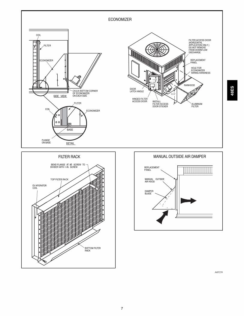
Economizer with solid--state controls and barometric reliefdampers includes filter racks and provide outdoor air during cool-ing and reduce compressor operation.Manual outside air damper includes hood and filter rack with ad-justable damper blade for up to 25% outdoor air.Flat roof curbs in both 8 in. and 14 in. sizes are available for roofmounted applications.
Square--to--round duct transition kit enables 018--048 size unitsto be fitted to 14 in. round ductwork.Compressor hard start kit assists compressor start--up by provid-ing additional starting torque on single phase units and prolongscompressor motor life.
Corporate Thermostats provide control for the system heatingand cooling functions. Thermostatmodels are available in both pro-grammable and non--programmable versions.
Crankcase heater provides anti--floodback protection for low--load cooling applications.
Natural--to--propane gas conversion kit allows for conversionfrom natural gas to propane gas for standard altitude (0 to 2000 ftabove sea level).Rigging kit includes lifting bracketswhich are inserted into the unitbase rigging holds to lift unit for rooftop applications.
Low--ambient kit (Motormaster II control) allows the use ofme-chanical cooling down to outdoor temperatures as low as 0_Fwhenproperly installed.Solid--state Time Guard II device provides short--cycling protec-tion for the compressor.Not requiredwith corporate electronic ther-mostats.Filterrack featureseasy installation, serviceability, and high--filter-ing performance for vertical applications.High altitude propane conversion kit is for use at 2001 to 6000ft above sea level. Kit consists of propane gas orifices that compen-sate for gas heat operation at high altitude.Propane--to--natural conversion kit is for use at standard altitudes(0 to 2000 ft above sea level). Kit contains natural gas orifices toconvert the unit back to natural gas.
48ES
7
ECONOMIZER
COIL
FILTER
SIDE VIEW
CAULK BOTTOM CORNEROF ECONOMIZERON EACH SIDE
BASE
COIL
FLANGEON BASE DETAIL
ECONOMIZER
FI LTER
FILTER ACCESS DOOR(HORIZONTALAPPLICATION ONLY.)DO NOT REMOVEFROM DOWNFLOWDISCHARGE.
REPLACEMENTPANEL
HOLE FORECONOMIZERWIRING HARDNESS
DOORLATCH ANGLE
HINGED FILTERACCESS DOOR INSTALL
FILTER ACCESSDOOR STICKER
ALUMINUMFILTER
RAINHOOD11 13/32”�
17 13/32
16 1/4”�
EV APORATORCOIL
TOP FILTER RACK
BEND FLANGE AT 90̊�-SCREW TODIVIDER WITH 1-IN. SCREW
BOTTOM FILTERRACK
DAMPERBLADE
MANUAL OUTSIDEAIR HOOD
REPLACEMENTPANEL
ECONOMIZER
FILTER RACK MANUAL OUTSIDE AIR DAMPER
A05239
48ES
8
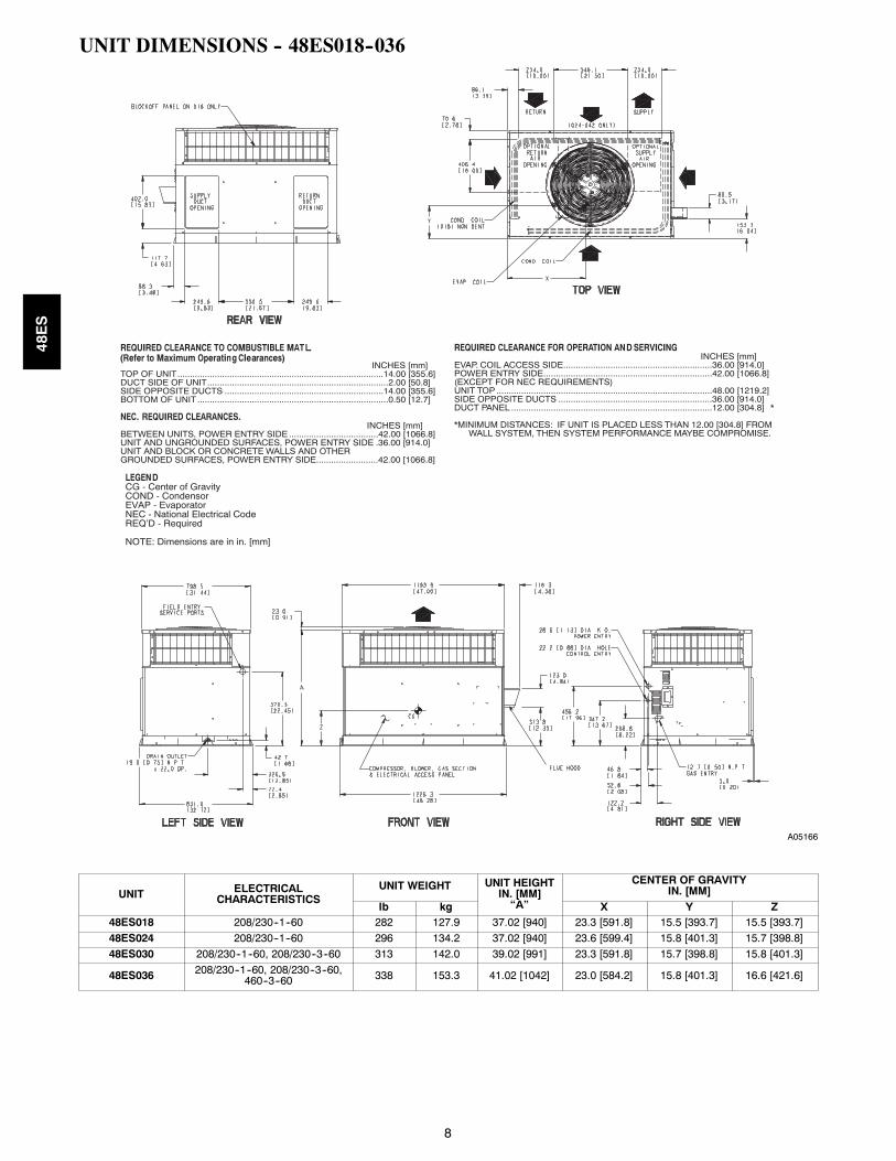
UNIT DIMENSIONS -- 48ES018--036
REQUIRED CLEARANCE FOR OPERATION AND SERVICINGINCHES [mm]
EVAP. COIL ACCESS SIDE............................................................36.00 [914.0]POWER ENTRY SIDE....................................................................42.00 [1066.8](EXCEPT FOR NEC REQUIREMENTS)UNIT TOP .......................................................................................48.00 [1219.2]SIDE OPPOSITE DUCTS ..............................................................36.00 [914.0]DUCT PANEL .................................................................................12.00 [304.8] *
*MINIMUM DISTANCES: IF UNIT IS PLACED LESS THAN 12.00 [304.8] FROM WALL SYSTEM, THEN SYSTEM PERFORMANCE MAYBE COMPROMISE.
REQUIRED CLEARANCE TO COMBUSTIBLE MATL.
INCHES [mm]TOP OF UNIT...................................................................................14.00 [355.6]DUCT SIDE OF UNIT.........................................................................2.00 [50.8]SIDE OPPOSITE DUCTS ................................................................14.00 [355.6]BOTTOM OF UNIT .............................................................................0.50 [12.7]
NEC. REQUIRED CLEARANCES.INCHES [mm]
BETWEEN UNITS, POWER ENTRY SIDE ....................................42.00 [1066.8]UNIT AND UNGROUNDED SURFACES, POWER ENTRY SIDE .36.00 [914.0]UNIT AND BLOCK OR CONCRETE WALLS AND OTHERGROUNDED SURFACES, POWER ENTRY SIDE.........................42.00 [1066.8]
LEGENDCG - Center of GravityCOND - CondensorEVAP - EvaporatorNEC - National Electrical CodeREQ’D - Required
NOTE: Dimensions are in in. [mm]
(Refer to Maximum Operating Clearances)
A05166
UNIT ELECTRICALCHARACTERISTICS
UNIT WEIGHT UNIT HEIGHTIN. [MM]
“A”
CENTER OF GRAVITYIN. [MM]
lb kg X Y Z48ES018 208/230--1--60 282 127.9 37.02 [940] 23.3 [591.8] 15.5 [393.7] 15.5 [393.7]
48ES024 208/230--1--60 296 134.2 37.02 [940] 23.6 [599.4] 15.8 [401.3] 15.7 [398.8]
48ES030 208/230--1--60, 208/230--3--60 313 142.0 39.02 [991] 23.3 [591.8] 15.7 [398.8] 15.8 [401.3]
48ES036 208/230--1--60, 208/230--3--60,460--3--60 338 153.3 41.02 [1042] 23.0 [584.2] 15.8 [401.3] 16.6 [421.6]
48ES

9
UNIT DIMENSIONS -- 48ES042--060
REQUIRED CLEARANCE FOR OPERATION AND SERVICINGINCHES [mm]
EVAP. COIL ACCESS SIDE............................................................36.00 [914.0]POWER ENTRY SIDE....................................................................42.00 [1066.8](EXCEPT FOR NEC REQUIREMENTS)UNIT TOP .......................................................................................48.00 [1219.2]SIDE OPPOSITE DUCTS ..............................................................36.00 [914.0]DUCT PANEL .................................................................................12.00 [304.8] *
*MINIMUM DISTANCES: IF UNIT IS PLACED LESS THAN 12.00 [304.8] FROM WALL SYSTEM, THEN SYSTEM PERFORMANCE MAYBE COMPROMISE.
REQUIRED CLEARANCE TO COMBUSTIBLE MATL.INCHES [mm]
TOP OF UNIT...................................................................................14.00 [355.6]DUCT SIDE OF UNIT.........................................................................2.00 [50.8]SIDE OPPOSITE DUCTS ................................................................14.00 [355.6]BOTTOM OF UNIT .............................................................................0.50 [12.7]ELECTRIC HEAT PANEL .................................................................36.00 [914.4]
NEC. REQUIRED CLEARANCES.INCHES [mm]
BETWEEN UNITS, POWER ENTRY SIDE ....................................42.00 [1066.8]UNIT AND UNGROUNDED SURFACES, POWER ENTRY SIDE .36.00 [914.0]UNIT AND BLOCK OR CONCRETE WALLS AND OTHERGROUNDED SURFACES, POWER ENTRY SIDE.........................42.00 [1066.8]
LEGENDCG - Center of GravityCOND - CondensorEVAP - EvaporatorNEC - National Electrical CodeREQ’D - Required
NOTE: Dimensions are in in. [mm]
A05142
UNIT ELECTRICALCHARACTERISTICS
UNIT WEIGHT UNIT HEIGHTIN. [MM]
“A”
CENTER OF GRAVITYIN. [MM]
lb kg X Y Z48ES042 208/230--1--60, 208/230--3--60, 460--3--60 401 181.9 42.98 [1092] 25.5 [647.7] 20.5 [520.7] 17.1 [434.3]
48ES048 208/230--1--60, 208/230--3--60, 460--3--60 418 189.6 42.98 [1092] 25.2 [640.1] 20.7 [525.8] 17.4 [442.0]
48ES060 208/230--1--60, 208/230--3--60, 460--3--60 446 202.3 46.98 [1193] 25.5 [647.7] 21.0 [533.4] 17.6 [447.0]
48ES

10
ACCESSORY DIMENSIONS
Gask et aroundouter edge
Insulateddeck pan
Gask et aroundduct
S/AR/A
HVAC unitbase
*Gask etingouter flange
Flashing fieldsupplied
Roofing materialfield supplied
Cant str ipfield supplied
*Provided with roof curb
Roof
Ductworkfield supplied
Insulation (fieldsupplied)
Roof curb*
Wood nailer*
Gask etinginner flange*
Scre w(NO TE A)
Roof Curb for Small Cabinet
Note A: When unit mounting scre w is used,retainer bra cke t must also be used.
HVAC unitbase
*Gask etingouter flange
Flashing fieldsupplied
Roofing materialfield supplied
Cant str ipfield supplied
*Provided with roof curb
Roof
Ductworkfield supplied
Insulation (fieldsupplied)
Roof curb*
Wood nailer*
Gask etinginner flange*
Scre w(NOTE A)
Roof Curb for Large Cabinet
Note A: When unit mounting scre w is used,retainer bra cket must also be used.
A
B Typ.
Supply opening(B x C)
LongSupport
D
F
Return opening(B X C)
Insulateddeck pan
ShortSupport
C Typ.
G
E
F
G
DE
A05308
UNIT SIZE ODS CATALOGNUMBER
AIN. (MM)
BIN. (MM)
CIN. (MM)
DIN. (MM)
EIN. (MM)
FIN. (MM)
GIN. (MM)
48ES018--036CPRFCURB006A00 8 (203) 11 (279) 16--1/2 (419) 28--3/4 (730) 30--3/8 (771) 44--5/16 (1126) 45--15/16 (1167)CPRFCURB007A00 14 (356) 11 (279) 16--1/2 (419) 28--3/4 (730) 30--3/8 (771) 44--5/16 (1126) 45--15/16 (1167)
48ES042--060CPRFCURB008A00 8 (203) 16--3/16 (411) 17--3/8 (441) 40--1/4 (1022) 41--15/16 (1065) 44--7/16 (1129) 46--1/16 (1169)CPRFCURB009A00 14 (356) 16--3/16 (411) 17--3/8 (441) 40--1/4 (1022) 41--15/16 (1065) 44--7/16 (1129) 46--1/16 (1169)
NOTES:
1. Roof curb must be set up for unit being installed.2. Seal strip must be applied, as required, to unit being installed.3. Dimensions are in inches.4. Roof curb is made of 16--gauge steel.5. Attach ductwork to curb (flanges of duct rest on curb).6. Insulated panels: 1--in. thick fiberglass 1 lb. density.7. When unit mounting screw is used (see Note A), a retainer bracket must be used as well. This bracket must also be used when required by code for hurricane or seismic
conditions. This bracket is available through Micrometl.
48ES

11
1 2
3 4A07216
DETAIL A
A05161
CORNER WEIGHTS (SMALL CABINET) CORNER WEIGHTS (LARGE CABINET)
Unit018 024 030 036 Unit 042 048 060
lb kg lb kg lb kg lb kg Total Weight lb kg lb kg lb kg
Total Weight 282 127.9 296 134.2 313 142.0 338 153.3 Total Weight 401 181.9 418 189.6 446 202.3
Corner Weight1
73 33.1 59 26.8 55 25.1 72 32.5 Corner Weight1
68 30.6 62 28.1 54 24.5
Corner Weight2
60 27.4 84 38.0 95 42.9 89 40.3 Corner Weight2
119 53.8 135 61.2 158 71.7
Corner Weight3
95 43.0 81 36.8 78 35.2 95 43.0 Corner Weight3
60 27.2 64 29.2 81 36.6
Corner Weight4
54 24.4 72 32.6 85 38.7 83 37.5 Corner Weight4
155 70.3 157 71.1 154 69.7
Rigging Weight 301 136.5 315 142.9 332 150.6 357 161.9 Rigging Weight 423 191.8 440 199.5 468 212.2
ShippingWeight
336 152.4 350 158.7 367 166.4 392 177.8 ShippingWeight
463 210.0 480 217.7 508 230.4
SELECTION PROCEDURE (WITH EXAMPLE)1. Determine cooling and heating requirements atdesign conditions:Given:
Required Cooling Capacity (TC) 34,000 Btuh. . . . . . . . . .Sensible Heat Capacity (SHC) 25,000 Btuh. . . . . . . . . . . .Required Heating Capacity 60,000 Btuh. . . . . . . . . . . . . . .
Condenser Entering Air Temperature 95°F. . . . . . . . . . . . .Indoor--Air Temperature 80°F edb 67°F ewb. . . . . . . . . . . .
Evaporator Air Quantity 1200 CFM. . . . . . . . . . . . . . . . . .External Static Pressure 0.100 in. wc. . . . . . . . . . . . . . . . . .Electrical Characteristics 208--1--60. . . . . . . . . . . . . . . . . . .
2. Select unit based on required cooling capacity.Enter Net Cooling Capacities table at condenser entering tempera-ture of 95°F. Unit 036 at 1200 cfm and 67°F ewb (entering wetbulb) will provide a total capacity of 36,000 Btuh and a SHC of27,400 Btuh. Calculate SHC correction, if required, using Note 4under Cooling Capacities tables.
3. Select heating capacity of unit to providedesign condition requirement.In the Heating Capacities and Efficiencies table, note that the unit036090 will provide 72,000 Btuh with an input of 90,000 Btuh.
4. Determine fan speed and power requirementsat design conditions.Before entering the air delivery tables, calculate the total static pres-sure required. From the given example, theWet Coil Pressure DropTable, and the Filter Pressure Drop Table:External Static Pressure 0.100 in. wc
Filter 0.130 in. wcWet Coil Pressure Drop 0.059 in. wc
Total Static Pressure 0.289 in. wcEnter the table for Dry Coil Air Delivery—horizontal and down-flow Discharge. For 208v operation, deduct 10% from the valuegiven. At 0.33 ESP (external static pressure), the fan will deliver1404 cfm at medium speed. The fan speed should be set at mediumspeed.
5. Select unit that corresponds to power sourceavailable.The Electrical Data Table shows that the unit is designed to operateat 208--1--60.
48ES
12
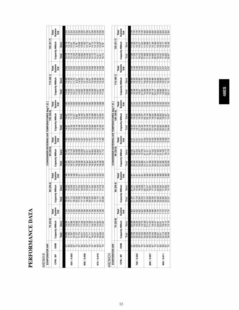
PERFORMANCEDATA
48ES018
EVAPORATORAIR
CONDENSERENTERINGAIRTEMPERATURESdegF(C)
75(23.9)
85(29.4)
95(35.0)
105(40.6)
115(46.1)
125(51.7)
CFM/BF
EWB
CapacityMBtuh
Total
System
KW
CapacityMBtuh
Total
System
KW
CapacityMBtuh
Total
System
KW
CapacityMBtuh
Total
System
KW
CapacityMBtuh
Total
System
KW
CapacityMBtuh
Total
System
KW
Total
Sens
Total
Sens
Total
Sens
Total
Sens
Total
Sens
Total
Sens
525/0.003
5716.99
16.99
1.34
16.32
16.32
1.48
15.62
15.62
1.65
14.87
14.87
1.83
14.06
14.06
2.03
13.18
13.18
2.24
6217.60
16.01
1.33
16.77
15.60
1.48
15.89
15.18
1.65
14.97
14.73
1.83
14.06
14.06
2.03
13.18
13.18
2.24
6317.97
12.99
1.33
17.12
12.59
1.48
16.22
12.19
1.65
15.28
11.75
1.83
14.25
11.30
2.03
13.16
10.81
2.24
6719.35
13.43
1.33
18.45
13.04
1.48
17.51
12.63
1.65
16.49
12.21
1.83
15.41
11.75
2.03
14.25
11.28
2.24
7221.27
10.85
1.33
20.30
10.47
1.48
19.28
10.08
1.64
18.19
9.66
1.83
17.03
9.23
2.02
15.78
8.76
2.24
600/0.006
5717.74
17.74
1.36
17.03
17.03
1.51
16.28
16.28
1.67
15.48
15.48
1.85
14.62
14.62
2.05
13.69
13.69
2.26
6218.01
17.26
1.36
17.15
16.83
1.51
16.28
16.28
1.67
15.49
15.49
1.85
14.62
14.62
2.05
13.69
13.69
2.26
6318.37
13.83
1.36
17.48
13.43
1.51
16.54
13.01
1.67
15.55
12.57
1.85
14.49
12.11
2.05
13.36
11.62
2.27
6719.77
14.33
1.36
18.83
13.93
1.51
17.84
13.51
1.67
16.78
13.08
1.85
15.66
12.62
2.05
14.46
12.13
2.26
7221.71
11.39
1.35
20.70
11.01
1.50
19.63
10.61
1.67
18.50
10.19
1.85
17.29
9.75
2.05
16.00
9.28
2.27
675/0.010
5718.37
18.37
1.38
17.63
17.63
1.53
16.84
16.84
1.70
15.99
15.99
1.88
15.09
15.09
2.08
14.10
14.10
2.29
6218.37
18.37
1.38
17.63
17.63
1.53
16.84
16.84
1.70
15.99
15.99
1.88
15.09
15.09
2.08
14.10
14.10
2.29
6318.67
14.65
1.38
17.75
14.24
1.53
16.78
13.82
1.70
15.76
13.37
1.88
14.67
12.90
2.08
13.51
12.39
2.29
6720.08
15.20
1.38
19.11
14.79
1.53
18.08
14.37
1.70
17.00
13.93
1.88
15.84
13.46
2.08
14.61
12.97
2.29
7222.04
11.92
1.38
20.99
11.53
1.53
19.89
11.12
1.69
18.72
10.70
1.88
17.48
10.25
2.08
16.15
9.78
2.29
48ES024
EVAPORATORAIR
CONDENSERENTERINGAIRTEMPERATURESdegF(C)
75(23.9)
85(29.4)
95(35.0)
105(40.6)
115(46.1)
125(51.7)
CFM/BF
EWB
CapacityMBtuh
Total
System
KW
CapacityMBtuh
Total
System
KW
CapacityMBtuh
Total
System
KW
CapacityMBtuh
Total
System
KW
CapacityMBtuh
Total
System
KW
CapacityMBtuh
Total
System
KW
Total
Sens
Total
Sens
Total
Sens
Total
Sens
Total
Sens
Total
Sens
700/0.004
5722.08
22.08
1.62
21.24
21.24
1.81
20.35
20.35
2.01
19.40
19.40
2.24
18.38
18.38
2.49
17.26
17.26
2.76
6222.78
19.89
1.62
21.71
19.41
1.81
20.59
18.91
2.01
19.43
19.35
2.24
18.38
18.38
2.49
17.26
17.26
2.76
6323.26
16.29
1.62
22.16
15.82
1.81
21.00
15.33
2.01
19.77
14.82
2.24
18.48
14.29
2.49
17.10
13.73
2.76
6725.03
16.83
1.62
23.84
16.36
1.81
22.60
15.87
2.01
21.29
15.36
2.24
19.91
14.83
2.49
18.43
14.27
2.76
7227.53
13.73
1.62
26.23
13.26
1.81
24.86
12.78
2.01
23.43
12.27
2.24
21.92
11.75
2.49
20.29
11.20
2.76
800/0.007
5723.08
23.08
1.66
22.17
22.17
1.85
21.21
21.21
2.05
20.18
20.18
2.28
19.09
19.09
2.53
17.89
17.89
2.80
6223.33
21.47
1.66
22.23
22.07
1.85
21.21
21.21
2.05
20.18
20.18
2.28
19.08
19.08
2.53
17.89
17.89
2.80
6323.76
17.40
1.66
22.60
16.91
1.85
21.38
16.41
2.05
20.10
15.89
2.28
18.76
15.35
2.53
17.33
14.77
2.80
6725.55
18.00
1.66
24.30
17.52
1.85
23.00
17.02
2.05
21.63
16.50
2.28
20.19
15.96
2.53
18.66
15.39
2.80
7228.08
14.47
1.66
26.72
14.00
1.85
25.28
13.50
2.06
23.79
12.98
2.28
22.21
12.45
2.53
20.52
11.89
2.80
900/0.011
5723.91
23.91
1.70
22.94
22.94
1.89
21.92
21.92
2.09
20.83
20.83
2.32
19.66
19.66
2.57
18.40
18.40
2.84
6223.91
23.91
1.70
22.94
22.94
1.89
21.92
21.92
2.09
20.83
20.83
2.32
19.66
19.66
2.57
18.40
18.40
2.84
6324.13
18.47
1.70
22.92
17.97
1.89
21.66
17.46
2.09
20.35
16.92
2.32
18.96
16.37
2.57
17.50
15.77
2.84
6725.93
19.14
1.70
24.64
18.65
1.89
23.29
18.14
2.09
21.88
17.61
2.32
20.40
17.05
2.57
18.82
16.46
2.84
7228.49
15.19
1.70
27.07
14.70
1.89
25.59
14.19
2.10
24.04
13.67
2.32
22.41
13.13
2.57
20.67
12.56
2.84
48ES

13
PERFORMANCEDATA(CONT)
48ES030
EVAPORATORAIR
CONDENSERENTERINGAIRTEMPERATURESdegF(C)
75(23.9)
85(29.4)
95(35.0)
105(40.6)
115(46.1)
125(51.7)
CFM/BF
EWB
CapacityMBtuh
Total
System
KW
CapacityMBtuh
Total
System
KW
CapacityMBtuh
Total
System
KW
CapacityMBtuh
Total
System
KW
CapacityMBtuh
Total
System
KW
CapacityMBtuh
Total
System
KW
Total
Sens
Total
Sens
Total
Sens
Total
Sens
Total
Sens
Total
Sens
875/0.009
5727.63
27.63
2.04
26.49
26.49
2.25
25.27
25.27
2.49
23.94
23.94
2.74
22.50
22.50
3.01
20.94
20.94
3.31
6228.17
25.17
2.04
26.78
24.51
2.25
25.33
25.15
2.49
23.94
23.94
2.74
22.50
22.50
3.01
20.94
20.94
3.31
6328.67
20.21
2.04
27.24
19.59
2.25
25.71
18.94
2.49
24.08
18.25
2.74
22.34
17.53
3.01
20.49
16.76
3.30
6730.82
20.91
2.05
29.28
20.29
2.26
27.63
19.63
2.49
25.87
18.95
2.75
23.99
18.22
3.02
21.99
17.45
3.31
7233.80
16.64
2.05
32.10
16.03
2.27
30.28
15.38
2.50
28.36
14.71
2.75
26.28
13.98
3.03
24.08
13.23
3.32
1000/0.013
5728.69
28.69
2.09
27.47
27.47
2.31
26.16
26.16
2.54
24.74
24.74
2.79
23.21
23.21
3.07
21.54
21.54
3.36
6228.77
28.54
2.09
27.47
27.47
2.31
26.16
26.16
2.54
24.74
24.74
2.79
23.21
23.21
3.07
21.54
21.54
3.36
6329.16
21.52
2.09
27.67
20.88
2.31
26.07
20.22
2.54
24.38
19.51
2.79
22.58
18.77
3.07
20.68
17.98
3.36
6731.33
22.30
2.10
29.72
21.67
2.31
28.00
21.00
2.55
26.18
20.30
2.80
24.24
19.55
3.07
22.17
18.76
3.36
7234.34
17.47
2.10
32.57
16.84
2.32
30.67
16.18
2.55
28.68
15.50
2.81
26.52
14.77
3.08
24.25
14.00
3.37
1125/0.019
5729.57
29.57
2.15
28.28
28.28
2.36
26.88
26.88
2.59
25.39
25.39
2.85
23.77
23.77
3.12
22.01
22.01
3.42
6229.56
29.56
2.15
28.27
28.27
2.36
26.88
26.88
2.59
25.39
25.39
2.85
23.77
23.77
3.12
22.01
22.01
3.42
6329.52
22.77
2.15
27.98
22.13
2.36
26.34
21.44
2.59
24.60
20.72
2.85
22.76
19.95
3.12
20.82
19.11
3.41
6731.70
23.65
2.15
30.03
23.00
2.36
28.26
22.32
2.60
26.40
21.60
2.85
24.41
20.83
3.13
22.30
20.00
3.42
7234.73
18.26
2.16
32.90
17.63
2.37
30.94
16.96
2.60
28.89
16.27
2.86
26.67
15.53
3.13
24.34
14.76
3.42
48ES036
EVAPORATORAIR
CONDENSERENTERINGAIRTEMPERATURESdegF(C)
75(23.9)
85(29.4)
95(35.0)
105(40.6)
115(46.1)
125(51.7)
CFM/BF
EWB
CapacityMBtuh
Total
System
KW
CapacityMBtuh
Total
System
KW
CapacityMBtuh
Total
System
KW
CapacityMBtuh
Total
System
KW
CapacityMBtuh
Total
System
KW
CapacityMBtuh
Total
System
KW
Total
Sens
Total
Sens
Total
Sens
Total
Sens
Total
Sens
Total
Sens
1050/0.002
5732.76
32.76
2.31
31.53
31.53
2.56
30.22
30.22
2.84
28.82
28.82
3.15
27.30
27.30
3.48
25.63
25.63
3.85
6233.56
29.11
2.31
32.01
28.44
2.56
30.39
27.73
2.84
28.82
28.82
3.15
27.30
27.30
3.48
25.63
25.63
3.85
6334.27
23.75
2.31
32.67
23.09
2.56
30.98
22.40
2.84
29.20
21.68
3.15
27.28
20.92
3.48
25.21
20.11
3.85
6736.87
24.54
2.31
35.16
23.89
2.57
33.36
23.20
2.85
31.45
22.49
3.15
29.40
21.73
3.49
27.19
20.92
3.85
7240.54
19.93
2.32
38.69
19.28
2.58
36.71
18.60
2.85
34.62
17.89
3.16
32.38
17.14
3.50
29.97
16.34
3.86
1200/0.004
5734.22
34.22
2.36
32.89
32.89
2.62
31.49
31.49
2.90
29.98
29.98
3.20
28.34
28.34
3.54
26.55
26.55
3.91
6234.37
31.46
2.36
32.89
32.89
2.62
31.49
31.49
2.90
29.98
29.98
3.20
28.34
28.34
3.54
26.55
26.55
3.91
6334.97
25.40
2.37
33.30
24.72
2.62
31.54
24.02
2.90
29.68
23.28
3.20
27.69
22.50
3.54
25.55
21.67
3.90
6737.61
26.29
2.37
35.82
25.62
2.62
34.00
24.93
2.90
31.94
24.19
3.21
29.81
23.42
3.54
27.53
22.59
3.91
7241.33
21.04
2.38
39.38
20.37
2.63
37.31
19.68
2.91
35.13
18.95
3.22
32.80
18.19
3.55
30.30
17.38
3.91
1350/0.008
5735.44
35.44
2.42
34.03
34.03
2.68
32.53
32.53
2.95
30.93
30.93
3.26
29.20
29.20
3.60
27.30
27.30
3.96
6235.44
35.44
2.42
34.03
34.03
2.68
32.53
32.53
2.95
30.93
30.93
3.26
29.20
29.20
3.60
27.30
27.30
3.96
6335.50
26.99
2.42
33.77
26.30
2.68
31.95
25.59
2.95
30.03
24.83
3.26
27.98
24.03
3.60
25.80
23.16
3.96
6738.16
27.99
2.43
36.31
27.31
2.68
34.36
26.60
2.96
32.30
25.85
3.27
30.11
25.06
3.60
27.77
24.21
3.96
7241.91
22.10
2.44
39.89
21.42
2.69
37.74
20.71
2.97
35.48
19.98
3.27
33.09
19.21
3.61
30.51
18.39
3.97
48ES

14
PERFORMANCEDATA(CONT)
48ES042
EVAPORATORAIR
CONDENSERENTERINGAIRTEMPERATURESdegF(C)
75(23.9)
85(29.4)
95(35.0)
105(40.6)
115(46.1)
125(51.7)
CFM/BF
EWB
CapacityMBtuh
Total
System
KW
CapacityMBtuh
Total
System
KW
CapacityMBtuh
Total
System
KW
CapacityMBtuh
Total
System
KW
CapacityMBtuh
Total
System
KW
CapacityMBtuh
Total
System
KW
Total
Sens
Total
Sens
Total
Sens
Total
Sens
Total
Sens
Total
Sens
1225/0.011
5739.26
39.26
2.88
37.63
37.63
3.20
35.88
35.88
3.55
34.00
34.00
3.94
31.96
31.96
4.35
29.76
29.76
4.80
6240.35
36.68
2.89
38.34
35.70
3.21
36.22
34.64
3.56
34.03
33.95
3.94
31.96
31.96
4.35
29.76
29.76
4.80
6341.07
29.58
2.90
39.00
28.64
3.22
36.79
27.65
3.56
34.46
26.62
3.94
31.99
25.54
4.35
29.39
24.41
4.79
6744.14
30.58
2.93
41.87
29.62
3.24
39.47
28.62
3.59
36.94
27.57
3.97
34.25
26.48
4.37
31.44
25.34
4.81
7248.32
24.44
2.96
45.81
23.49
3.28
43.17
22.50
3.63
40.38
21.47
4.00
37.41
20.39
4.41
34.32
19.28
4.84
1400/0.016
5740.77
40.77
2.97
39.02
39.02
3.29
37.13
37.13
3.64
35.10
35.10
4.02
32.92
32.92
4.44
30.58
30.58
4.88
6241.18
39.33
2.98
39.13
38.81
3.29
37.13
37.13
3.64
35.10
35.10
4.02
32.92
32.92
4.44
30.58
30.58
4.88
6341.80
31.43
2.98
39.62
30.46
3.30
37.31
29.45
3.64
34.89
28.39
4.02
32.32
27.28
4.43
29.64
26.11
4.87
6744.88
32.54
3.01
42.50
31.56
3.32
40.00
30.54
3.67
37.37
29.47
4.05
34.58
28.34
4.45
31.68
27.18
4.89
7249.11
25.59
3.05
46.48
24.62
3.36
43.73
23.62
3.71
40.83
22.57
4.08
37.75
21.47
4.49
34.56
20.35
4.92
1575/0.023
5742.02
42.02
3.06
40.15
40.15
3.38
38.14
38.14
3.73
35.99
35.99
4.11
33.68
33.68
4.52
31.22
31.22
4.96
6242.02
42.02
3.06
40.14
40.14
3.38
38.14
38.14
3.73
35.99
35.99
4.11
33.68
33.68
4.52
31.22
31.22
4.96
6342.32
33.20
3.06
40.06
32.21
3.38
37.68
31.17
3.72
35.19
30.08
4.10
32.55
28.93
4.51
29.81
27.71
4.95
6745.41
34.43
3.09
42.95
33.43
3.40
40.37
32.39
3.75
37.66
31.29
4.12
34.80
30.13
4.53
31.84
28.92
4.97
7249.67
26.70
3.13
46.95
25.71
3.44
44.12
24.70
3.79
41.12
23.64
4.16
37.96
22.53
4.56
34.69
21.39
5.00
48ES048
EVAPORATORAIR
CONDENSERENTERINGAIRTEMPERATURESdegF(C)
75(23.9)
85(29.4)
95(35.0)
105(40.6)
115(46.1)
125(51.7)
CFM/BF
EWB
CapacityMBtuh
Total
System
KW
CapacityMBtuh
Total
System
KW
CapacityMBtuh
Total
System
KW
CapacityMBtuh
Total
System
KW
CapacityMBtuh
Total
System
KW
CapacityMBtuh
Total
System
KW
Total
Sens
Total
Sens
Total
Sens
Total
Sens
Total
Sens
Total
Sens
1400/0.009
5746.24
46.24
3.34
44.25
44.25
3.75
42.10
42.10
4.20
39.79
39.79
4.69
37.27
37.27
5.21
34.57
34.57
5.77
6247.38
41.31
3.34
44.96
40.19
3.75
42.39
38.97
4.20
39.78
39.78
4.69
37.27
37.27
5.21
34.57
34.57
5.77
6348.22
33.26
3.35
45.72
32.19
3.76
43.06
31.05
4.20
40.24
29.86
4.69
37.23
28.61
5.21
34.06
27.31
5.77
6751.54
34.27
3.36
48.83
33.18
3.77
45.97
32.05
4.22
42.91
30.85
4.70
39.67
29.60
5.22
36.28
28.30
5.77
7256.08
27.21
3.37
53.10
26.13
3.78
49.97
25.02
4.23
46.62
23.85
4.71
43.09
22.63
5.23
39.41
21.38
5.78
1600/0.014
5747.90
47.90
3.43
45.77
45.77
3.84
43.47
43.47
4.29
40.98
40.98
4.77
38.30
38.30
5.29
35.44
35.44
5.85
6248.26
44.29
3.43
45.80
45.74
3.84
43.46
43.46
4.29
40.98
40.98
4.77
38.30
38.30
5.29
35.44
35.44
5.85
6348.98
35.32
3.43
46.37
34.22
3.84
43.61
33.07
4.29
40.67
31.85
4.77
37.56
30.57
5.29
34.30
29.23
5.85
6752.30
36.46
3.44
49.48
35.36
3.85
46.50
34.20
4.30
43.33
32.98
4.78
39.99
31.70
5.30
36.50
30.37
5.86
7256.88
28.48
3.46
53.77
27.39
3.87
50.52
26.26
4.31
47.05
25.07
4.79
43.40
23.84
5.31
39.62
22.58
5.86
1800/0.020
5749.26
49.26
3.51
46.99
46.99
3.93
44.56
44.56
4.37
41.93
41.93
4.86
39.11
39.11
5.38
36.11
36.11
5.94
6249.26
49.26
3.51
46.99
46.99
3.93
44.56
44.56
4.37
41.93
41.93
4.86
39.11
39.11
5.38
36.11
36.11
5.94
6349.52
37.31
3.52
46.82
36.18
3.93
43.98
35.00
4.37
40.96
33.76
4.86
37.78
32.44
5.38
34.46
31.03
5.93
6752.84
38.59
3.53
49.92
37.46
3.94
46.86
36.28
4.38
43.60
35.04
4.87
40.18
33.72
5.38
36.63
32.34
5.94
7257.43
29.71
3.54
54.22
28.61
3.95
50.88
27.47
4.40
47.31
26.27
4.88
43.58
25.03
5.39
39.71
23.76
5.94
48ES
15
PERFORMANCEDATA(CONT)
48ES060
EVAPORATORAIR
CONDENSERENTERINGAIRTEMPERATURESdegF(C)
75(23.9)
85(29.4)
95(35.0)
105(40.6)
115(46.1)
125(51.7)
CFM/BF
EWB
CapacityMBtuh
Total
System
KW
CapacityMBtuh
Total
System
KW
CapacityMBtuh
Total
System
KW
CapacityMBtuh
Total
System
KW
CapacityMBtuh
Total
System
KW
CapacityMBtuh
Total
System
KW
Total
Sens
Total
Sens
Total
Sens
Total
Sens
Total
Sens
Total
Sens
1750/0.010
5757.18
57.18
4.12
54.74
54.74
4.57
52.17
52.17
5.08
49.44
49.44
5.62
46.49
46.49
6.21
43.26
43.26
6.85
6258.24
53.17
4.13
55.28
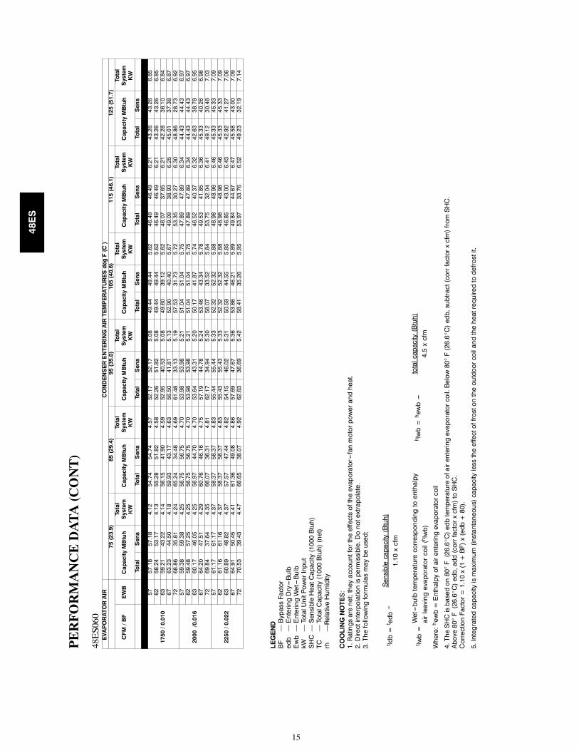
51.82
4.58
52.26
51.82
5.08
49.44
49.44
5.62
46.49
46.49
6.21
43.26
43.26
6.85
6359.21
43.22
4.14
56.15
41.90
4.59
52.95
40.53
5.08
49.60
39.12
5.62
46.07
37.65
6.21
42.28
36.10
6.84
6763.23
44.50
4.18
59.93
43.17
4.63
56.50
41.81
5.13
52.90
40.40
5.67
49.09
38.93
6.25
45.01
37.38
6.87
7268.86
35.81
4.24
65.24
34.48
4.69
61.48
33.13
5.19
57.53
31.73
5.72
53.35
30.27
6.30
48.86
28.73
6.92
2000/0.016
5759.38
59.38
4.25
56.75
56.75
4.70
53.98
53.98
5.21
51.04
51.04
5.75
47.89
47.89
6.34
44.43
44.43
6.97
6259.48
57.25
4.25
56.75
56.75
4.70
53.98
53.98
5.21
51.04
51.04
5.75
47.89
47.89
6.34
44.43
44.43
6.97
6360.17
46.05
4.25
56.97
44.70
4.70
53.64
43.31
5.20
50.17
41.87
5.74
46.52
40.37
6.32
42.63
38.78
6.95
6764.20
47.51
4.29
60.76
46.16
4.75
57.19
44.78
5.24
53.46
43.34
5.78
49.53
41.85
6.36
45.33
40.26
6.98
7269.84
37.64
4.35
66.07
36.31
4.81
62.17
34.94
5.30
58.07
33.52
5.84
53.75
32.04
6.41
49.12
30.48
7.03
2250/0.022
5761.17
61.17
4.37
58.37
58.37
4.83
55.44
55.44
5.33
52.32
52.32
5.88
48.98
48.98
6.46
45.33
45.33
7.09
6261.16
61.16
4.37
58.37
58.37
4.83
55.43
55.43
5.33
52.32
52.32
5.88
48.98
48.98
6.46
45.33
45.33
7.09
6360.89
48.82
4.37
57.57
47.44
4.82
54.15
46.02
5.31
50.59
44.55
5.85
46.85
43.00
6.43
42.92
41.27
7.06
6764.91
50.45
4.41
61.36
49.08
4.86
57.69
47.67
5.36
53.86
46.21
5.89
49.84
44.67
6.47
45.58
43.00
7.09
7270.53
39.43
4.47
66.65
38.07
4.92
62.63
36.69
5.42
58.41
35.26
5.95
53.97
33.76
6.52
49.23
32.19
7.14
LEGEND
BF—BypassFactor
edb—EnteringDry---Bulb
Ewb—EnteringWet---Bulb
kW—TotalUnitPowerInput
SHC—SensibleHeatCapacity(1000Btuh)
TC—TotalCapacity(1000Btuh)(net)
rh—RelativeHumidity
COOLINGNOTES:
1.Ratingsarenet;theyaccountfortheeffectsoftheevaporator---fanmotorpowerandheat.
2.Directinterpolationispermissible.Donotextrapolate.
3.Thefollowingformulasmaybeused:
Sensiblecapacity(Btuh)
1.10xcfm
t ldb=t edb---
Wet---bulbtemperaturecorrespondingtoenthalpy
airleavingevaporatorcoil(hlwb)
t lwb=
totalcapacity(Btuh)
4.5xcfm
h lwb=h ewb---
Where:hewb=Enthalpyofairenteringevaporatorcoil
4.TheSHCisbasedon80
°F(26.6_C)edbtemperatureofairenteringevaporatorcoil.Below80
°F(26.6_C)edb,subtract(corrfactorxcfm)fromSHC.
Above80
°F(26.6_C)edb,add(corrfactorxcfm)toSHC.
CorrectionFactor=1.10x(1+BF)x(edb+80).
5.Integratedcapacityismaximum(instantaneous)capacitylesstheeffectoffrostontheoutdoorcoilandtheheatrequiredtodefrostit.
48ES

16
PERFORMANCE DATA (CONT)
Dry Coil Air Delivery* -- Horizontal and Downflow Discharge --Unit 48ES024--036 (Deduct 10% for 208 Volts)
Unit Heating RiseRange oF
MotorSpeed
External Static Pressure (in. wc)0.1 0.2 0.3 0.4 0.5 0.6 0.7 0.8 0.9
48ES(---,N)018040 30 --- 60
Low1Watts 260 243 229 217 209 --- --- --- --- --- --- --- ---CFM 859 775 667 536 382 --- --- --- --- --- --- --- ---
Heating Rise oF 35 39 45 56 NA NA NA NA NA
HighWatts 340 328 317 307 300 294 --- --- --- --- --- ---CFM 1064 948 820 680 528 364 --- --- --- --- --- ---
Heating Rise oF NA 32 37 44 57 NA NA NA NA
48ES(---,N)024040 20 --- 50
Low1Watts 311 309 304 301 286 290 286 280 --- ---CFM 935 885 820 757 686 583 423 263 --- ---
Heating Rise oF 32 34 37 40 44 NA NA NA NA
MediumWatts 411 405 398 390 379 357 357 345 327CFM 1195 1155 1100 1028 957 868 769 647 365
Heating Rise oF 25 26 27 29 31 35 39 46 NA
HighWatts 528 518 509 492 477 467 447 435 421CFM 1484 1421 1368 1279 1185 1088 970 853 712
Heating Rise oF 20 21 22 23 25 28 31 35 42
48ES(---,N)024060 35 --- 65
Low1Watts 311 309 304 301 286 290 286 280 --- ---CFM 935 885 820 757 686 583 423 263 --- ---
Heating Rise oF 48 51 55 59 NA NA NA NA NA
MediumWatts 411 405 398 390 379 357 357 345 327CFM 1195 1155 1100 1028 957 868 769 647 365
Heating Rise oF 38 39 41 44 47 52 59 NA NA
HighWatts 528 518 509 492 477 467 447 435 421CFM 1484 1421 1368 1279 1185 1088 970 853 712
Heating Rise oF NA NA NA 35 38 41 46 53 63
48ES(---,N)030040 20 --- 50
LowWatts 311 309 304 301 286 290 286 280 --- ---CFM 935 885 820 757 686 583 423 263 --- ---
Heating Rise oF 32 34 37 40 44 NA NA NA NA
Medium1Watts 411 405 398 390 379 357 357 345 327CFM 1195 1155 1100 1028 957 868 769 647 365
Heating Rise oF 25 26 27 29 31 35 39 46 NA
HighWatts 528 518 509 492 477 467 447 435 421CFM 1484 1421 1368 1279 1185 1088 970 853 712
Heating Rise oF 20 21 22 23 25 28 31 35 42
48ES(---,N)030060 35 --- 65
LowWatts 311 309 304 301 286 290 286 280 --- ---CFM 935 885 820 757 686 583 423 263 --- ---
Heating Rise oF 48 51 55 59 NA NA NA NA NA
Medium1Watts 411 405 398 390 379 357 357 345 327CFM 1195 1155 1100 1028 957 868 769 647 365
Heating Rise oF 38 39 41 44 47 52 59 NA NA
HighWatts 528 518 509 492 477 467 447 435 421CFM 1484 1421 1368 1279 1185 1088 970 853 712
Heating Rise oF NA NA NA 35 38 41 46 53 63
48ES(---,N)036060 25 --- 55
Low1Watts 439 429 415 401 395 380 356 339 329CFM 1242 1170 1089 994 917 837 702 570 442
Heating Rise oF 36 38 41 45 49 54 NA NA NA
MediumWatts 503 491 479 461 450 436 418 404 389CFM 1320 1244 1162 1081 1005 897 767 662 541
Heating Rise oF 34 36 39 42 45 50 NA NA NA
HighWatts 641 627 623 609 601 588 571 559 548CFM 1362 1288 1205 1119 1033 933 826 714 580
Heating Rise oF 33 35 37 40 44 48 54 NA NA
48ES(---,N)036090 40 --- 70
Low1Watts 439 429 415 401 395 380 356 339 329CFM 1242 1170 1089 994 917 837 702 570 442
Heating Rise oF 54 58 62 68 NA NA NA NA NA
MediumWatts 503 491 479 461 450 436 418 404 389CFM 1320 1244 1162 1081 1005 897 767 662 541
Heating Rise oF 51 54 58 62 67 NA NA NA NA
HighWatts 641 627 623 609 601 588 571 559 548CFM 1362 1288 1205 1119 1033 933 826 714 580
Heating Rise oF 50 52 56 60 65 NA NA NA NA
48ES

17
PERFORMANCE DATA (CONT)Dry Coil Air Delivery* -- Horizontal and Downflow Discharge --Unit 48ES042--060 (Deduct 10% for 208 Volts)
Unit Heating RiseRange oF
MotorSpeed
External Static Pressure (in. wc)0.1 0.2 0.3 0.4 0.5 0.6 0.7 0.8 0.9
48ES(---,N)042060 25 --- 55
Low1Watts 559 540 522 503 483 464 445 425 406CFM 1405 1370 1330 1283 1230 1171 1106 1034 957
Heating Rise oF 32 33 34 35 37 38 41 44 47
MediumWatts 665 647 629 609 589 567 545 521 497CFM 1593 1552 1505 1452 1394 1330 1260 1184 1102
Heating Rise oF 28 29 30 31 32 34 36 38 41
HighWatts 815 795 775 754 734 715 695 676 656CFM 1764 1710 1652 1591 1525 1456 1383 1306 1225
Heating Rise oF 26 26 27 28 30 31 33 34 37
48ES(---,N)042090 40 --- 70
Low1Watts 559 540 522 503 483 464 445 425 406CFM 1405 1370 1330 1283 1230 1171 1106 1034 957
Heating Rise oF 48 49 51 53 55 58 61 65 NA
MediumWatts 665 647 629 609 589 567 545 521 497CFM 1593 1552 1505 1452 1394 1330 1260 1184 1102
Heating Rise oF 42 43 45 46 48 51 54 57 61
HighWatts 815 795 775 754 734 715 695 676 656CFM 1764 1710 1652 1591 1525 1456 1383 1306 1225
Heating Rise oF NA NA 41 42 44 46 49 52 55
48ES(---,N)048090 25 --- 55
LowWatts 627 617 607 584 567 548 528 503 480CFM 1550 1530 1493 1461 1414 1361 1320 1250 1177
Heating Rise oF 44 44 45 46 48 50 51 54 NA
Medium1Watts 771 755 734 711 690 665 639 607 572CFM 1798 1771 1734 1687 1645 1595 1530 1449 1355
Heating Rise oF 38 38 39 40 41 42 44 47 50
HighWatts 969 941 908 887 858 827 804 767 748CFM 2124 2071 2000 1944 1876 1811 1735 1647 1555
Heating Rise oF 32 33 34 35 36 37 39 41 43
48ES(---,N)048115 35 --- 65
LowWatts 627 617 607 584 567 548 528 503 480CFM 1550 1530 1493 1461 1414 1361 1320 1250 1177
Heating Rise oF 56 56 58 59 61 63 65 NA NA
Medium1Watts 771 755 734 711 690 665 639 607 572CFM 1798 1771 1734 1687 1645 1595 1530 1449 1355
Heating Rise oF 48 49 50 51 52 54 56 60 64
HighWatts 969 941 908 887 858 827 804 767 748CFM 2124 2071 2000 1944 1876 1811 1735 1647 1555
Heating Rise oF 41 42 43 44 46 48 50 52 55
48ES(---,N)048130 40 --- 70
LowWatts 627 617 607 584 567 548 528 503 480CFM 1550 1530 1493 1461 1414 1361 1320 1250 1177
Heating Rise oF 63 64 65 67 69 NA NA NA NA
Medium1Watts 771 755 734 711 690 665 639 607 572CFM 1798 1771 1734 1687 1645 1595 1530 1449 1355
Heating Rise oF 54 55 56 58 59 61 64 67 NA
HighWatts 969 941 908 887 858 827 804 767 748CFM 2124 2071 2000 1944 1876 1811 1735 1647 1555
Heating Rise oF 46 47 49 50 52 54 56 59 63
48ES(---,N)060090 25 --- 55
Low1Watts 786 769 754 736 722 705 684 658 616CFM 2027 1960 1901 1821 1759 1693 1616 1513 1354
Heating Rise oF 33 34 36 37 38 40 42 45 50
MediumWatts 873 849 833 815 798 782 763 748 704CFM 2095 2026 1962 1887 1817 1748 1679 1583 1439
Heating Rise oF 32 33 34 36 37 39 40 43 47
HighWatts 1012 993 981 963 948 927 904 886 846CFM 2184 2109 2036 1963 1886 1812 1729 1647 1496
Heating Rise oF 31 32 33 34 36 37 39 41 45
48ES(---,N)060115 35 --- 65
Low1Watts 786 769 754 736 722 705 684 658 616CFM 2027 1960 1901 1821 1759 1693 1616 1513 1354
Heating Rise oF 43 44 45 47 49 51 53 57 64
MediumWatts 873 849 833 815 798 782 763 748 704CFM 2095 2026 1962 1887 1817 1748 1679 1583 1439
Heating Rise oF 41 43 44 46 47 49 51 54 60
HighWatts 1012 993 981 963 948 927 904 886 846CFM 2184 2109 2036 1963 1886 1812 1729 1647 1496
Heating Rise oF 39 41 42 44 46 48 50 52 58
48ES(---,N)060130 40 --- 70
Low1Watts 786 769 754 736 722 705 684 658 616CFM 2027 1960 1901 1821 1759 1693 1616 1513 1354
Heating Rise oF 48 50 51 54 55 58 60 64 NA
MediumWatts 873 849 833 815 798 782 763 748 704CFM 2095 2026 1962 1887 1817 1748 1679 1583 1439
Heating Rise oF 47 48 50 52 54 56 58 62 68
HighWatts 1012 993 981 963 948 927 904 886 846CFM 2184 2109 2036 1963 1886 1812 1729 1647 1496
Heating Rise oF 45 46 48 50 52 54 56 59 65* Air delivery values are without air filter and are for dry coil (See Table 15 -- 48ES Wet Coil Pressure Drop table).1 Factory--shipped heating/cooling speedNA = Not allowed for heating speedNote: Deduct field--supplied air filter pressure drop and wet coil pressure drop to obtain external static pressure available for ducting.
48ES
18
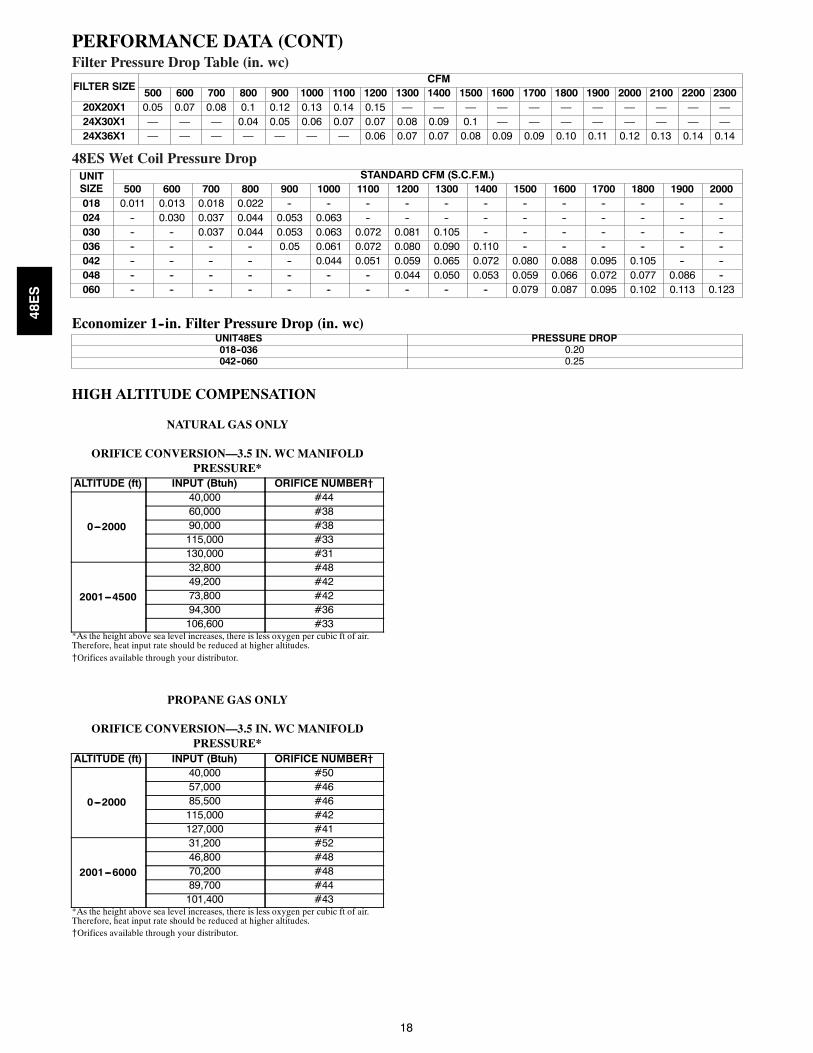
PERFORMANCE DATA (CONT)Filter Pressure Drop Table (in. wc)
FILTER SIZECFM
500 600 700 800 900 1000 1100 1200 1300 1400 1500 1600 1700 1800 1900 2000 2100 2200 230020X20X1 0.05 0.07 0.08 0.1 0.12 0.13 0.14 0.15 — — — — — — — — — — —24X30X1 — — — 0.04 0.05 0.06 0.07 0.07 0.08 0.09 0.1 — — — — — — — —24X36X1 — — — — — — — 0.06 0.07 0.07 0.08 0.09 0.09 0.10 0.11 0.12 0.13 0.14 0.14
48ES Wet Coil Pressure DropUNITSIZE
STANDARD CFM (S.C.F.M.)500 600 700 800 900 1000 1100 1200 1300 1400 1500 1600 1700 1800 1900 2000
018 0.011 0.013 0.018 0.022 -- -- -- -- -- -- -- -- -- -- -- --024 -- 0.030 0.037 0.044 0.053 0.063 -- -- -- -- -- -- -- -- -- --030 -- -- 0.037 0.044 0.053 0.063 0.072 0.081 0.105 -- -- -- -- -- -- --036 -- -- -- -- 0.05 0.061 0.072 0.080 0.090 0.110 -- -- -- -- -- --042 -- -- -- -- -- 0.044 0.051 0.059 0.065 0.072 0.080 0.088 0.095 0.105 -- --048 -- -- -- -- -- -- -- 0.044 0.050 0.053 0.059 0.066 0.072 0.077 0.086 --060 -- -- -- -- -- -- -- -- -- -- 0.079 0.087 0.095 0.102 0.113 0.123
Economizer 1--in. Filter Pressure Drop (in. wc)UNIT48ES PRESSURE DROP018--036 0.20042--060 0.25
HIGH ALTITUDE COMPENSATION
NATURAL GAS ONLY
ORIFICE CONVERSION—3.5 IN. WC MANIFOLDPRESSURE*
ALTITUDE (ft) INPUT (Btuh) ORIFICE NUMBER†
0---2000
40,000 #4460,000 #3890,000 #38115,000 #33130,000 #31
2001---4500
32,800 #4849,200 #4273,800 #4294,300 #36106,600 #33
*As the height above sea level increases, there is less oxygen per cubic ft of air.Therefore, heat input rate should be reduced at higher altitudes.{Orifices available through your distributor.
PROPANE GAS ONLY
ORIFICE CONVERSION—3.5 IN. WC MANIFOLDPRESSURE*
ALTITUDE (ft) INPUT (Btuh) ORIFICE NUMBER†
0---2000
40,000 #5057,000 #4685,500 #46115,000 #42127,000 #41
2001---6000
31,200 #5246,800 #4870,200 #4889,700 #44101,400 #43
*As the height above sea level increases, there is less oxygen per cubic ft of air.Therefore, heat input rate should be reduced at higher altitudes.{Orifices available through your distributor.
48ES

19
TYPICAL PIPING AND WIRING
INDOORTHERMOSTAT
DISCONNECTPER NEC*
FROMPOWERSOURCE
RETURNAIR
TOP COVER
FROMGAS LINE
ROOF
RETURN-AIRFLEXIBLE DUCT
CEILINGCONCENTRIC DIFFUSER BOX(FIELD-SUPPLIED)
SUPPLY-AIRFLEXIBLE DUCT
ROOF-MOUNTINGCURB
*NEC - NATIONAL ELECTRICAL CODE
VERTICAL DISCHARGE
48ES

20
APPLICATION DATA
Condensate trap—A2--in. condensate trapmustbe field supplied.Ductwork— Secure downflow discharge ductwork to roof curb.For horizontal discharge applications, attach ductwork to unit withflanges.To convert a unit to downflow discharge—Units are equippedwith factory--installed inserts in the down--flow openings. Removalof the inserts is similar to removing an electrical knock--out. Use theduct cover to seal the horizontal discharge openings in the unit.Units installed in horizontal discharge orientation do not requireduct covers.
Airflow—Units are draw--thru in the coolingmode and blow--thruin the heating mode.
Maximum cooling airflow—To minimize the possibility of con-densate blow--off from the evaporator, airflow through the unitsshould not exceed 450 cfm per ton.Minimumcooling airflow—Minimumcooling airflow is 350 cfmper ton.Minimum ambient cooling operation temperature— All stan-dard units have aminimum ambient operating temperature of 40_F(4_C).With accessory low ambient temperature kit, units can oper-ate at temperatures down to 0_F (--17_C).
Minimum temperature—Air entering the heat exchanger in heat-ing mode must be a minimum of 50_F (10_C)continuous and/or45_F (7_C) intermittent.
48ES
21
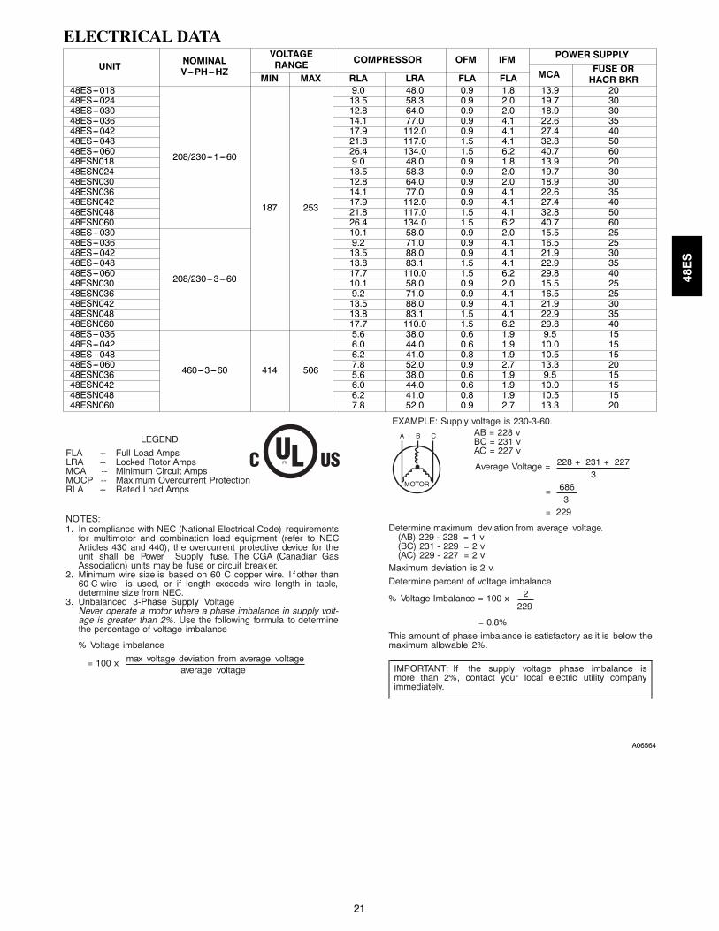
ELECTRICAL DATA
UNIT NOMINALV---PH---HZ
VOLTAGERANGE COMPRESSOR OFM IFM POWER SUPPLY
MCA FUSE ORHACR BKRMIN MAX RLA LRA FLA FLA
48ES---018
208/230---1---60
187 253
9.0 48.0 0.9 1.8 13.9 2048ES---024 13.5 58.3 0.9 2.0 19.7 3048ES---030 12.8 64.0 0.9 2.0 18.9 3048ES---036 14.1 77.0 0.9 4.1 22.6 3548ES---042 17.9 112.0 0.9 4.1 27.4 4048ES---048 21.8 117.0 1.5 4.1 32.8 5048ES---060 26.4 134.0 1.5 6.2 40.7 6048ESN018 9.0 48.0 0.9 1.8 13.9 2048ESN024 13.5 58.3 0.9 2.0 19.7 3048ESN030 12.8 64.0 0.9 2.0 18.9 3048ESN036 14.1 77.0 0.9 4.1 22.6 3548ESN042 17.9 112.0 0.9 4.1 27.4 4048ESN048 21.8 117.0 1.5 4.1 32.8 5048ESN060 26.4 134.0 1.5 6.2 40.7 6048ES---030
208/230---3---60
10.1 58.0 0.9 2.0 15.5 2548ES---036 9.2 71.0 0.9 4.1 16.5 2548ES---042 13.5 88.0 0.9 4.1 21.9 3048ES---048 13.8 83.1 1.5 4.1 22.9 3548ES---060 17.7 110.0 1.5 6.2 29.8 4048ESN030 10.1 58.0 0.9 2.0 15.5 2548ESN036 9.2 71.0 0.9 4.1 16.5 2548ESN042 13.5 88.0 0.9 4.1 21.9 3048ESN048 13.8 83.1 1.5 4.1 22.9 3548ESN060 17.7 110.0 1.5 6.2 29.8 4048ES---036
460---3---60 414 506
5.6 38.0 0.6 1.9 9.5 1548ES---042 6.0 44.0 0.6 1.9 10.0 1548ES---048 6.2 41.0 0.8 1.9 10.5 1548ES---060 7.8 52.0 0.9 2.7 13.3 2048ESN036 5.6 38.0 0.6 1.9 9.5 1548ESN042 6.0 44.0 0.6 1.9 10.0 1548ESN048 6.2 41.0 0.8 1.9 10.5 1548ESN060 7.8 52.0 0.9 2.7 13.3 20
228 = 1 v229 = 2 v227 = 2 v
LEGEND
FLA -- Full Load AmpsLRA -- Locked Rotor AmpsMCA -- Minimum Circuit AmpsMOCP -- Maximum Overcurrent ProtectionRLA -- Rated Load Amps
NO TES:1. In compliance with NEC (National Electrical Code) requirements
for multimotor and combination load equipment (refer to NE CArticles 430 and 440), the overcurrent protective device for theunit shall be Power Supply fuse. The CGA (Canadian GasAssociation) units may be fuse or circuit break er.
2. Minimum wire size is based on 60 C copper wire. I f other than60 C wire is used, or if length exceeds wire length in table,determine siz e from NEC..
3. Unbalanced 3-Phase Supply VoltageNever operate a motor where a phase imbalance in supply volt-age is greater than 2%. Use the following formula to determinethe percentage of voltage imbalance.
% Voltage imbalance
max voltage deviation from average voltage= 100 xaverage voltage
EXAMPLE: Supply voltage is 230-3-60.AB = 228 vBC = 231 vAC = 227 v
228 + 231 + 227Average Voltage =3
686=3
= 229
Determine maximum deviation from average voltage.(AB) 229 -(BC) 231 -(AC) 229 -
Maximum deviation is 2 v.
Determine percent of voltage imbalance.2% Voltage Imbalance = 100 x
229
= 0.8%
This amount of phase imbalance is satisfactory as it is below themaximum allowable 2%.
IMPORTANT: If the supply voltage phase imbalance ismore than 2%, contact your local electric utility companyimmediately.
(R)
A06564
48ES
22
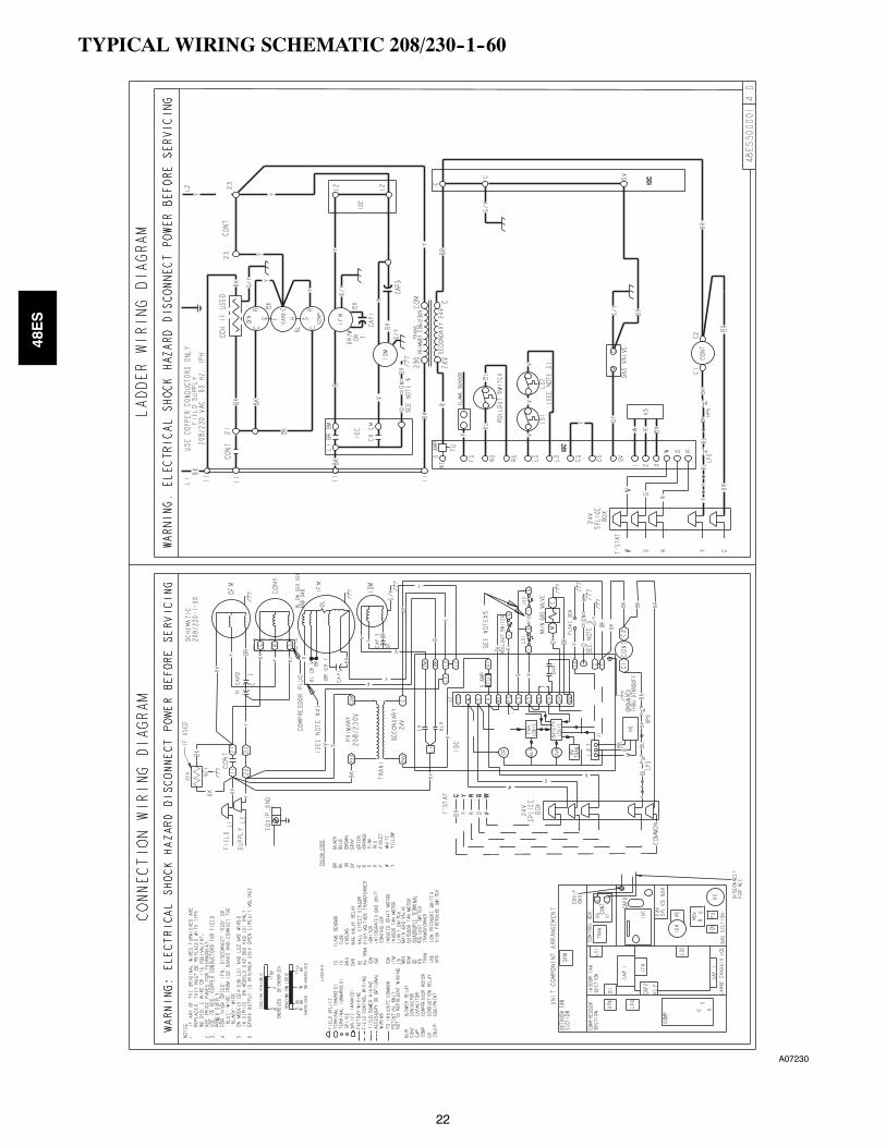
TYPICAL WIRING SCHEMATIC 208/230--1--60
A07230
48ES
23
TYPICAL WIRING SCHEMATIC 208/230--3--60
A07232
48ES

24
TYPICAL WIRING SCHEMATIC 460--3--60
A07231
48ES
25
CONTROLS
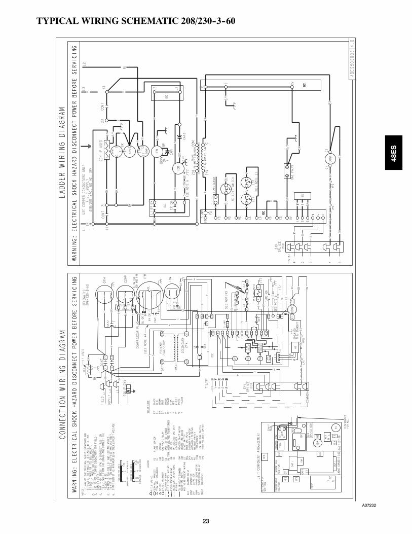
Operating sequenceHeating—When the thermostat calls for heating, terminal “W” isenergized, starting the induced draft motor. When the hall--effectsensor on the induced--draft motor senses that it has reached the re-quired speed, the burner ignition sequence begins. The indoor(evaporator) fan motor (IFM) is energized 45 seconds after flame isestablished. When the thermostat is satisfied and “W” is de--ener-gized, the IFM stops after a 45--second time--off delay. Please notethat the ignition control board (IGC) has the capability to automati-cally reduce the indoor fan motor on and off delays in the event ofhigh duct static and/orpartially--clogged filter.An adjustmentof fandelays by the ignition control board is indicated by a flash code “1”on the LED on the IGC.Cooling—When the system thermostat calls for cooling, 24 V issupplied to the “Y“ and “G“ terminals of the thermostat. This com-pletes thecircuit to thecontactor coil (C)and indoor (evaporator) fanrelay (IFR). The normally open contacts of energized C close andcomplete the circuit through compressor motor (COMP) to outdoor(condenser) fan motor (OFM). Both motors start instantly. The setof normally open contacts of energized IFR close and complete thecircuit through IFM. The IFM starts instantly.
On the loss of the thermostat call for cooling, 24 V is removed fromboth the “Y” and “G“ terminals (provided the fan switch is in the“AUTO“ position) de--energizing the compressor contactor andopening the contacts supplying power to compressor/OFM. After a30--second delay, the IFM shuts off. If the thermostat fan selectorswitch is in the “ON“ position, the IFM will run continuously.NOTE: On units with a Time Guard® II device: Once the compres-sor has started and then stopped, it cannot be restarted again until 5minutes have elapsed.
48ES

26
GUIDE SPECIFICATIONS
Packaged Gas Heating/Electric Cooling UnitsConstant Volume Application
HVAC Guide SpecificationsSize Range: 1--1/2 to 5 Tons, Nominal Cooling
40,000 to 130,000 Btuh,Nominal Heating Input
Carrier Model Number: 48ESPart 1 — GeneralSYSTEM DESCRIPTION
Outdoor rooftop mounted, gas heating/electric cooling unit uti-lizing a hermetic scroll compressor for cooling duty. Unit shalldischarge supply air vertically or horizontally as shown on con-tract drawings. Condenser fan/coil section shall have a draw--thru design with vertical discharge for minimum sound levels.
QUALITY ASSURANCE
A. Unit shall be rated in accordance with ARI Standards210/240--03 and 270--95.
B. Unit shall be designed in accordance with UL Standard 1995.
C. Unit shall be manufactured in a facility registered to ISO 9001manufacturing quality standard.
D. Unit shall be UL listed and c--UL certified as a total package forsafety requirements.
E. Roof curb shall be designed to conform to NRCA Standards.
F. Insulation and adhesives shall meet NFPA 90A requirementsfor flame spread and smoke generation.
G. Cabinet insulation shall meet ASHRAE Standard 62P.
DELIVERY, STORAGE AND HANDLINGUnit shall be stored and handled permanufacturer’s recommen-dations.
Part 2 — ProductsEQUIPMENT
A. General:Factory--assembled, single--piece, heating and cooling unit. Con-tained within the enclosure shall be all factory wiring, piping, con-trols, refrigerant charge with R--410A refrigerant, and special fea-tures required prior to field start--up.
B. Unit Cabinet:
1. Unit cabinet shall be constructed of phosphated,zinc--coated, pre--painted steel capableofwith--standing 500hours in salt spray.
2. Normal service shall be through a single removable cabinetpanel.
3. Theunit shall beconstructed on a rust proof unit base thathasan externally trapped, integrated sloped drain.
4. Evaporator fan compartment top surface shall be insulatedwith aminimum 1/2--in. thick, flexible fiberglass insulation,coated on the air side and retained by adhesive andmechanical means. The evaporator wall sections will beinsulated with aminimum semi--rigid foil--faced board capa-bleofbeingwiped clean.Aluminumfoil--faced fiberglass in-sulation shall be used in the entire indoor air cavity section.
5. Unit shall have a field--supplied condensate trap.
C. Fans:
1. The evaporator fan shall be 3--speed (2--speed 018 size), di-rect--drive, as shown on equipment drawings.
2. Fan wheel shall be made from steel, be double--inlet typewith forward curved blades with corrosion resistant finish.Fan wheel shall be dynamically balanced.
3. Condenser fan shall be direct drive propeller type with alu-minum blades riveted to corrosion resistant steel spiders, bedynamically balanced, and discharge air vertically.
D. Compressor:
1. Fully hermetic compressorswith factory--installed vibrationisolation.
2. Scroll compressors shall be standard on all units.
E. Coils:Evaporator and condenser coils shall have aluminum plate finsmechanically bonded to seamless copper tubes with all jointsbrazed (Copper/copper and vinyl--coated construction avail-able as option). Tube sheet openings shall be belled to preventtube wear.
F. Heating Section:
1. Induced--draft combustion type with energy saving directspark ignition system and redundant main gas valve.
2. Induced--draft motors shall be provided with solid--statehall--effect sensor to ensure adequate airflow forcombustion.
3. The heat exchangers shall be constructed of aluminized steelfor corrosion resistance.
4. Burners shall beof the in--shot typeconstructed ofaluminumcoated steel.
5. All gas piping and electric power shall enter the unit cabinetat a single location.
G. Refrigerant Components:Refrigerant expansion device shall beof theTXV(thermostaticexpansion valve) type.
H. Filters:Filter section shall consist of field--installed, throwaway, 1--in.thick fiberglass filters of commercially available sizes.
I. Controls and Safeties:
1. Unit controls shall be complete with a self--contained lowvoltage control circuit.
2. Compressors shall incorporate a solid--state compressorprotector that provides reset capability.
J. Operating Characteristics:
1. Unit shall be capable of starting and running at 125_F(51_C) ambient outdoor temperature per maximum loadcriteria of ARI Standard 210.
2. Compressor with standard controls shall be capable of op-eration down to 40_F (4_C) ambient outdoor temperature.
3. Units shall be provided with fan time delay to prevent coldair delivery before the heat exchanger warms up.
4. Unit shall be provided with 30--second fan time delay afterthe thermostat is satisfied.
K. Electrical Requirements:All unit power wiring shall enter the unit cabinet at a single
location.
L. Motors:
1. Compressor motors shall be of the refrigerant--cooled typewith line--break thermal and current overload protection.
2. All fan motors shall have permanently lubricated bearings,and inherent, automatic reset, thermal overload protection.
3. Condenser fan motor shall be totally enclosed.
48ES

27
GUIDE SPECIFICATIONS (CONT)
M. Special Features Available:
1. Louvered Grille:Wire grille shall be standard on all units. Louvered grilleshall beavailableasa factory--installed option to providehailguard and vandalism protection.
2. Coil Options:Shall include factory--installed optional copper/copper andvinyl--coated refrigerant coils.
3. Economizer:
a. Economizer controls capable of providing free coolingusing outside air.
b. Equipped with low leakage dampers not to exceed 3%leakage, at 1.0 in. wc pressure differential.
c. Spring return motor shuts off outdoor damper on pow-er failure.
4. Flat Roof Curb:Curbs shall have seal strip and awood nailer for flashing andshall be installed per manufacturer’s instructions.
5. Manual Outdoor Air Damper:Package shall consist of damper, birdscreen, and rainhoodwhich can be preset to admit outdoor air for year--roundventilation.
6. Thermostat:To provide for one--stage heating and cooling in additionmanual or automatic changeover and indoor fan control.
7. Natural--to--Propane Conversion Kit:Shall be complete with all required hardware to convert topropane gas operation at 3.5 in. wc manifold pressure.
8. Propane--to--Natural Conversion KitShall be complete with all hardware to convert to natural gasat standard altitude (0 to 2000 ft above sea level).
9. Low Ambient Package:Shall consist of a solid--state control and condenser coil tem-perature sensor for controlling condenser--fan motor opera-tion, which shall allow unit to operate down to 0_F outdoorambient temperature when properly installed.
10. Filter Rack Kit:Shall provide filter mounting for downflow applications.
11. Square--To--Round Duct Transitions (018--048):Shall have the ability to convert the supply and return open-ings from rectangular to round.
12. Compressor Protection:Solid--state control shall protect compressor by preventing“short cycling.“
13. Crankcase Heater:Shall provide anti--floodback protection for low--load cool-ing applications.
14. High Altitude Propane Conversion Kit:Shall consist of natural gas orifices to compensate for gasheat operation at 2001 to 6000 ft above sea level.
15. Low NOx:Shall provideNOx reduction to valuesbelow 40nanograms/joule to meet California emission requirements as shippedfrom factory.
16. Compressor Hard Start Kit (single phase units only):Shall provide additional starting torque for single--phasecompressors.
48ES

28
Manufacturer reserves the right to discontinue, or change at any time, specifications or designs without notice and without incurring obligations.
Copyright Carrier Corporation 7310 W. Morris St. Indianapolis, IN 46231 Printed in U.S.A. edition date: 04/07
Replaces: NEW
Catalog No. 48ES---1PD
48ES