production flow analysis for the digital prepress · pdf fileproduction flow analysis for the...
TRANSCRIPT
Production Flow Analysis ForThe Digital Prepress Process
Prepared by: John Romi
Master’s Thesis within the project Digital Image (20 credits)at the Institute For Media Technology,
Royal Institute of Technology, August 1, 2001Supervisor: Henrik Kihlberg
Examiner: Prof. Nils Enlund (KTH)

Production Flow Analysis For The Digital Prepress Process
ABSTRACT
Increasingly, complex systems rely on advanced control systems, from cheap, fast computer disk drives and fl y-by-wire aircraft to automobiles, integrated chemical production complexes, semiconductor manufacturing systems, and manned / unmanned space systems. Yet, ironically, Control Engineering and Theory remain poorly understood outside a narrow technical community. Traditionally, Control Engineers have been responsible for system inte-gration because they add the last component to a complex system, and do system-wide.
This simulation attempts to build an experimental model that will act like a real system in important aspects. It is important to note that simulation models are descriptive, not prescrip-tive. They tell how a system works under given conditions, not how to arrange the conditions to make the system works best. Simulation does not optimize it merely describes. In many cases, a description is all that is required. In others, the number of choices is small enough so that every possible choice can be simulated.
In this paper, I describe an approach taken and experiences encountered in developing and applying simulation and modeling technologies to Prepress/ Repro companies.As such, the focus of this paper is aimed at addressing aspects of building a simulation model of a prepress department. First, I describe an approach of software simulation and modeling and also modeling as investigated with the Extend software. Second, I describe how to build the prepress model step by step with a detailed description of the production fl ow. Third, a system analyses and model verifi cation and validation.

Production Flow Analysis For The Digital Prepress Process
INLEDNING
Alltmer komplexa system förlitar sig på avancerade kontrollsystem. Från billiga snabba datorer och fl y-by-wire fl ygplan, integrerade kemiska produktionssystem, tillverkningssystem med semikonduktorer och bemannade / obemannade rymdsystem.Vad som kan ses som ironiskt är att kontrollteknik och teorier förblir dåligt förstådda utanför en begränsad tekniskt kunnig grupp. Traditionellt har kontrollingenjörer varit ansvariga för systemintegrationen, eftersom det är dom som lagt till den sista komponenten till det komplexa systemet, och som fortsättar att göra så inom hela systemet.
Den här simuleringen är en intention att bygga en experimentell modell som kommer att bete sig som det verkliga systemet i många viktiga aspekter. Det är viktigt att notera att simuleringsmodeller är beskrivande och inte föreskrivande. De visar hur olika system fungerar under angivna förhållanden men inte hur förutsättningarna skall vara arrangerade för att systemet ska fungera på bästa sätt. Simulering optimerar inte utan beskriver. I många fall är en beskrivning allt som behövs. I andra fall är antalet val så få att alla alternativ kan bli simulerade.
I denna rapport beskriver jag en infallsvinkel given av och erfarenheter erhållna från utvecklingen och appliceringen av simulerings- och modelleringstekniker till prepress eller reproföretag. Fokus på denna rapport är riktad mot att bygga en simuleringsmodell på en prepress avdelning. Först beskriver jag simuleringsmjukvara och modellering som undersökts med programmet Extend. Därefter beskriver jag hur jag bygger prepressmodellen steg för steg med en detaljerad beskrivning av produktionsfl ödet. Sist gör jag en systemanalys och en modellverifi ering och validering.

Production Flow Analysis For The Digital Prepress Process
TABLE OF CONTENTS
1 Approach 11.1 Introduction 11.2 Purpose of This Study 1
2 Background 22.1 Digital Image (Digital bild) 22.2 Problem 2
3 Modeling and Simulation 33.1 Introduction to Modeling and Simulation 33.2 Simulation 33.3 The Power of Simulation 43.4 Types of Simulation 43.5 Simulation Models 4
4 Using Extend 64.1 Blocks 64.2 Libraries 64.3 Dialogs 74.4 Connectors and Connections 7
5 Building the Prepress Model 85.1 Description of the Problem 85.2 Building the First Part of the Model 105.2.1 Job Arrival and the Start Block Job Arrival and the Start Block Job Arrival and the Start Block 105.2.2 The DTP Line 125.2.3 The Scanner Line 135.3 Adding RIP Line to the Model 135.3.1 The RIP Line 135.4 Adding More Operations to the Model 155.4.1 The Proofi ng Line 155.4.2 Adding New Blocks to the Model 175.5 Adding Plotter Blocks to the Model 19
6 Results 216.1 Analyzing the Model and Running the Simulation 216.1.1 Model Verifi cation 216.1.2 Model Validation 24
7 Discussion and Recommendations 29
8 References 31

1 Approach Production Flow Analysis For The Digital Prepress Process
1.1 IntroductionModeling and simulation are powerful techniques, many complex systems can be analyzed easily and effectively. By creating models similar to the actual systems we can study and test these systems, and by analyzing the results we can either buid, modify or improve the actual system. Even fi nd out answeres to some common questions like, what is the advantage of processing the fastest jobs fi rst? What if there are multiple lines of production on the same product? What if customers reject jobs or some parts of them just when they are about to get ready for manufac-turing? How do systems act in the short and long term? Does it take a long time to reach steady state behavior? These questions and problems add another level of complexity to already com-plicated systems and which of we can use Modeling and simulation to get some answers.
1.2 Purpose of this StudyThe purpose of this study is to analyze the production fl ow in a Prepress/ Repro company and to calculate operation time for all steps in the chain production from the arrival of materials to the completed printing plate. The material can be digital documents like text fi les, layout pro-gram fi les, digital images and illustrations, PDF and PS-fi les, or even the traditional photos and graphic fi lms. The material will then go through a serial of operations to reach the fi nal result, in this case are the printing plates.
The time of these operations will be measured and the structure of the production will be studied and traced to create a simulation model with the help of a simulation software called Extend. By inserting the data to the model we will be able to modify the production fl ow from its results. The model is also heavily inclined to show the critical points in the process and the bottlenecks in the system.
This study is also important to understand the modern Prepress/ Repro company structure and of cousce understanding the production fl ow enables us to get a better understanding for the system. And further to help future studies to fi nd suitable solutions to increase productivity and to minimize the unnecessary interruptions in the production fl ow.
1
1 APPROACH

Production Flow Analysis For The Digital Prepress Process2 Background
2.1 Digital Image (Digital Bild)Digital Bild is a three-year research project carried out between 1997 and 1999 at the Institute for Media Technology, Department of Electronic Media, in co-operation with The Media Technol-ogy Devision.The aim of the project is to fi nd methods for improving quality and productivity in the digital workfl ow from original to print production. The project covers analysing current performance, recommending improvments in working methods for improving quality and productivity in the digital workfl ow from original to print production. The project covers analysing current perfor-mance, recommending improvments in working and new technologies, publishing articles and presenting at trade fairs.The project is a collaboration between nine companies, Grafi ska Företagens Förbund and the IMT (Institute for Media Technology).
The Pilot Companies are as follows:
Fägerblads Repro, Västerås Fälths Tryckeri, Värnamo Grafi a Systemrepro, Göteborg Pressens Bild, Stockholm Ruter Press, Laholm Toters Tryckeri, Östervåla Sörmlands Grafi ska, Katarinaholm Tryckeri AB Framåt, Göteborg Munksjö Förpackningar, Nybr
The Criteria for participating in the project are that the companies rely on a prepress workfl ow and that they have personnel responsible developing and maintaining prepress activities. partici-pation requires that the company actively contributes to the research and has a clear intension to further improve its prepress preocess.
2.2 Problem In the last few years, huge and rapid developments in the graphic technology fi eld took place. The revolution of the new generation of personal computers delivered new tools, software and machines which gave the Desktop Publishing a brand new appearance and many advanced facilities. As a natural result of this great development, many changes occurred in the production system. It came into view to that production time has been drastically decreased, productivity increased and quality raised.
However at the same time, the new technology came with some new problems. The new system consists of computers equipped with advanced software, servers, digital photo-writers scanners, and more. All these parts should somehow be able to communicate with each other in a proper way. This also gave the necessity of networking and data communication in this fi eld which increased the complicity of the system.
2
2 BACKGROUND

Production Flow Analysis For The Digital Prepress Process3 Modeling & Simulation
3.1 Introduction to Modeling and SimulationModeling and simulation is a tool that was created for the use in making effective military deci-sions. A helpful planning or decision-assisting model is one that captures the basic elements of a situation or problem area that can be handled to provide manufactured experience effi ciently. That experience is then used as one input to guide choices of assets, tactics, or policy.
An effective model or a simulation also provides artifi cial experience, but now aimed to allow an operator or a team to achieve and maintain particular skills. Make note here that decision-assisting models can provide valuable training for decision makers, especially if either historical or theoretical situations are presented to illustrate the realistic effects of uncertainty in its many aspects on the decision-making environment, and then on the outcomes.
If the above is an acceptable overview of the modeling and simulation enterprise, then one can ask for the background, sensitivities, and expertise desirable in a well-prepared professional user of modeling and simulation. The fi rst observation is that today all such properties are unlikely to be embodied in one individual. What follows is a suggested order of priority for the types of talent and experience needed when a modeling and simulation enterprise is to be pursued.
Projects involving modeling and simulation should not be initiated without discussing one or more specifi c issues or questions to be examined. These questions should relate to the purposes of the organization guided by the decision-maker to be advised and should be as focused as pos-sible. It requires art and experience to identify such questions. Skill comes with practice.
This arena is the range of the basic designer problem formulator, whose proposals and direction set the stage for subsequent and more technical modeling steps.
Experience suggests that the case study approach is particularly valuable, because one learns how to formulate and conduct studies effectively by doing more than by merely hearing prin-ciples. Accessing historical examples is a natural way to proceed.
3.2 SimulationSimulation is a powerful tool for decision support. It provides a method for checking your understanding of the world around you, and helps you produce better results faster.
Simulation in general, is to pretend that one deals with a real system while really working with an imitation. In this report the imitation is a computer model of the simulated reality.
Simulation can be used to dynamic systems that change with time such as gas stations where cars come and go. Also, it is used in random systems where nobody can tell at exactly what time the next event is going to happen.
3
3 MODELING & SIMULATION
Production Flow Analysis For The Digital Prepress Process3 Modeling & Simulation
3.3 The power of simulationCombining the simulation ability to generate random numbers with a general programming language leads to very powerful analytical tools.
Consider a bank queue model where customers arrive, get serviced, and leave. We know that the only mathematically tractable problems require very strict assumptions: arrivals and service times must be memory less, the queue must have infi nite capacity, no customers balk or renege, and so on. Furthermore, we can only analyze the long-term behavior, not any transient behavior. In reality, none of these assumptions hold fully. More people arrive in the lunch hour than at other times. The queue is initially empty at opening, and must be empty at closing time. Customers balk and renege all the time, often for no clearly identifi able reason. Also, if you really have memory less servers, you better get your training program together!
Simulation can model all that and more. Simulation is limited only to what you set it to spend the time getting data and programming it in. Does your server get tired after 1PM? Simulate it! Are customers less likely to renege at noon (before lunch) than at 12:55 PM (after lunch)? Simulate it! You can make your model of the world include anything you want. Your data col-lection costs may be enormous, but you can put in pretty well anything you want.
3.4 Types of Simulation Discrete event: It considers only horizontal and vertical lines as an event at distinct points of time what we refer as Events. Between two consecutive items nothing happens.
Continuous: In some systems the state changes all the time, not just at time of some discrete events. For example water level in a reservoir with a given infl ow and discharge may change all the time. In such cases, continuous simulation is more appropriate. However, discrete event simulation can serve also as an approximation.
3.5 Simulation ModelsThe intractability of many analytical models makes it necessary to develop computer models of a system that can be used in experiments about the system. Simulation models a computer representation of the real system that allows us to observe the behavior of the system when changes are made in it.
A model is a logical description of how a system performs. Simulations involve designing a model of a system and carrying out experiments on it as it progresses through time. For exam-ple, the board game - Monopoly and the hotels and facilities of Atlantic City, are models of a real system. When you play Monopoly, you are simulating that system. Simulation with extend means that instead of interacting with a real system, you create a model which corresponds to it in certain aspects.
4

Production Flow Analysis For The Digital Prepress Process3 Modeling & Simulation
A model is used to describe how a real world activity will perform. Models also enable you to test hypotheses at a fraction on the cost of actually undertaking the activities that the models simulate.
One of the principal benefi ts of a model is that you can begin with a simple approximation of a process and gradually refi ne the model as your understanding of the process improves. This refi nement enables you to achieve good approximation of very complex problems surprisingly quickly. As refi nement increases, your model becomes more and more accurate.
5

Production Flow Analysis For The Digital Prepress Process4 Using Extend
An Extend model is a document that contains components called “blocks” usually with connec-tions between them. Each block contains procedural information as well as data that get inserted later. After creating the model, it should be modifi ed by adding blocks, moving connections, and changing the block’s data.
Extend is an important tool that can be useful for the following activities:
Predicting the course and results of certain actions.Understanding why observed events occur.Identifying problem areas before implementation.Exploring the effects of modifi cations.Confi rming that all variables are known.
Evaluating ideas and identifying ineffi ciencies.Gaining insight and simulating creative thinking.Communicating the integrity and feasibility of your plans.
4.1 Blocks A block in Extend is like any block diagram; it can be an action or a process. Information goes into the block and processed by the program. Then information transmits to the next block, pro-cessed, and goes to the next block, and so on.Extend provides many kinds of blocks. Some blocks, called Hierarchical Blocks, contain groups of other blocks. For example the Plotter block, which takes information from the simulation and presents it as visible information, in form of diagrams and numbers.
4.2 LibrariesThe libraries in Extend are like a bank of blocks. User can use more than one copy of the same block in each model. The entire defi nition for a block is saved in the library. Extend allows users to use a copy of the block and this is very useful, because it allows to store all the changes on each block for every single model. The two main libraries are the Generic Library and the Discrete Event Library. They provide an extensive set of iconic building blocks for modeling.
The following are some types of libraries:
Generic LibrarySimulation is usually divided into two categories: continuous and discrete event. TheGeneric library is used for continuous simulations where values change when timechanges.
Discrete Event library The other type of modes is the discrete event model. In this kind of models,model entities change state based on when the event occurs. The discrete Event library is used for models that use queues, page-specifi c attributes, and priorities.
6
4 USING EXTEND

Production Flow Analysis For The Digital Prepress Process4 Using Extend
Plotter LibraryContains most common types of plotters for graphing model output.
Manufacturing LibraryThis is an extension of the Discrete Event library. It includes blocks that are morepowerful and fl exible than the Discrete Event library blocks. The blocks are adjusted for modeling manufacturing, material handling, transportation, and otherdiscrete systems.
Statistics LibraryThe blocks in the statistics library provide a better control over random numbers, andremove initial bias for statistical analysis. Some of the blocks report statistical information for a particular type of block in the model, others start statistical calculations or control.
Electronic Engineering Libraries Used to simulate system level design of analog, digital, signal processing, and controlsystems.
Sample libraries A variety of disciplines that illustrate Extend´s scoop and features.
4.3 DialogsMost of the blocks have a dialog with them and it is quite easy to use. The dialog is used to enter values and settings before running the simulation and also to see the results as the simulation runs. Users can get more information about the library by reading the help dialog associated with every block.
4.4 Connectors and ConnectionsMost blocks in Extend have input and output connectors which transports information into a block and out from it. Some blocks might have many input and output connectors depending on the kind of block and certainly where to use it.The connections are lines that connect blocks. These lines show the fl ow of information through the model. The simulation itself is a series of calculations and actions that fl ows through the connections between the blocks.
7

Production Flow Analysis For The Digital Prepress Process5 Buiding The Prepress Model
Initially, when building a simulation model, it is easier to start with a simple model and then add details until reaching the fi nal model. By building the model in stages and with minimum details, enables us to test every single step during the building precess until we reach the fi nal complete model.
5.1 Description of the Problem A Prepress department intends to examine the fl ow of its production and to study the possibilities of increasing the productivity, and to discover the bottle necks in the system. We will try here to describe the production fl ow in a modern Prepress department in general:
A Prepress department consists usually of these sections:
Digital Scanners and Image Treatment Station: Scanning of photos, illustrations, fi lms ...etc, and convert them to digital information asseparate fi les, then save them somewhere available for the user.
DTP-Stations (Desktop Publishing Stations): Often Macs or sometimes PCs supported with some advanced image and layout software, such as Adobe PhotoShop, Adobe Illustrator, Adobe PageMaker, InDesign and QuarkXpress. All the desktop publishing stations, are usually connected to a server;mostly an OPI-Server.
Proofi ng Stations (Analog, Digital or both):Most of the orders coming in to the Prepress need proofi ng, just to show customers how the fi nal product is going to look like before printing.
RIP station (Raster Image Processor):RIP machines are always associated with special software that converts all color tones to dots and then send the information to the laser printer that produces fi lms.
Plate copying station: Copying fi lms to printing plates, exposing them and then sending them to the suitableprint houses, depending on many things as paper quality, desired fi nal quality, marketing … etc.
(Fig. 1) Illustration shows the production fl ow in a Prepress department
8
5 BUILDING THE PREPRESS MODEL
Production Flow Analysis For The Digital Prepress Process5 Buiding The Prepress Model
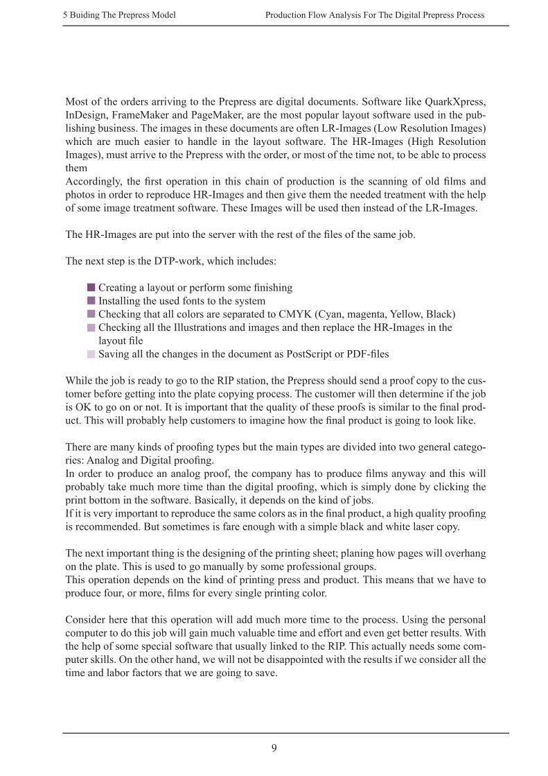
Most of the orders arriving to the Prepress are digital documents. Software like QuarkXpress, InDesign, FrameMaker and PageMaker, are the most popular layout software used in the pub-lishing business. The images in these documents are often LR-Images (Low Resolution Images) which are much easier to handle in the layout software. The HR-Images (High Resolution Images), must arrive to the Prepress with the order, or most of the time not, to be able to process themAccordingly, the fi rst operation in this chain of production is the scanning of old fi lms and photos in order to reproduce HR-Images and then give them the needed treatment with the help of some image treatment software. These Images will be used then instead of the LR-Images.
The HR-Images are put into the server with the rest of the fi les of the same job. The next step is the DTP-work, which includes:
Creating a layout or perform some fi nishing Installing the used fonts to the systemChecking that all colors are separated to CMYK (Cyan, magenta, Yellow, Black) Checking all the Illustrations and images and then replace the HR-Images in thelayout fi le Saving all the changes in the document as PostScript or PDF-fi les
While the job is ready to go to the RIP station, the Prepress should send a proof copy to the cus-tomer before getting into the plate copying process. The customer will then determine if the job is OK to go on or not. It is important that the quality of these proofs is similar to the fi nal prod-uct. This will probably help customers to imagine how the fi nal product is going to look like.
There are many kinds of proofi ng types but the main types are divided into two general catego-ries: Analog and Digital proofi ng. In order to produce an analog proof, the company has to produce fi lms anyway and this will probably take much more time than the digital proofi ng, which is simply done by clicking the print bottom in the software. Basically, it depends on the kind of jobs. If it is very important to reproduce the same colors as in the fi nal product, a high quality proofi ng is recommended. But sometimes is fare enough with a simple black and white laser copy.
The next important thing is the designing of the printing sheet; planing how pages will overhang on the plate. This is used to go manually by some professional groups. This operation depends on the kind of printing press and product. This means that we have to produce four, or more, fi lms for every single printing color.
Consider here that this operation will add much more time to the process. Using the personal computer to do this job will gain much valuable time and effort and even get better results. With the help of some special software that usually linked to the RIP. This actually needs some com-puter skills. On the other hand, we will not be disappointed with the results if we consider all the time and labor factors that we are going to save.
9
Production Flow Analysis For The Digital Prepress Process5 Buiding The Prepress Model
5.2 Building the First Part of the Model
5.2.1 Job Arrival and The Start blockThe fi rst part of the model is the job arrivals, the scanning and the DTP process.
It is important to notice that in this stage we will represent the model without extensions. And all variables are non-deterministic and replaced by ”1”, which I will replace later with the real numbers.
The most important thing here is to fi nd a defi nition for the parts of every job. In this case we found it logical to divide jobs into two kind of pages. The fi rst one are pages with photos and images that need treatment obtained for example from scanning. And the other kind is complete documents like text and HR-Images that do not need to go through scanning or any other pre-operation. This will help us defi ne two different types of pages. Practically, giving these two kinds two different attributes can do this.
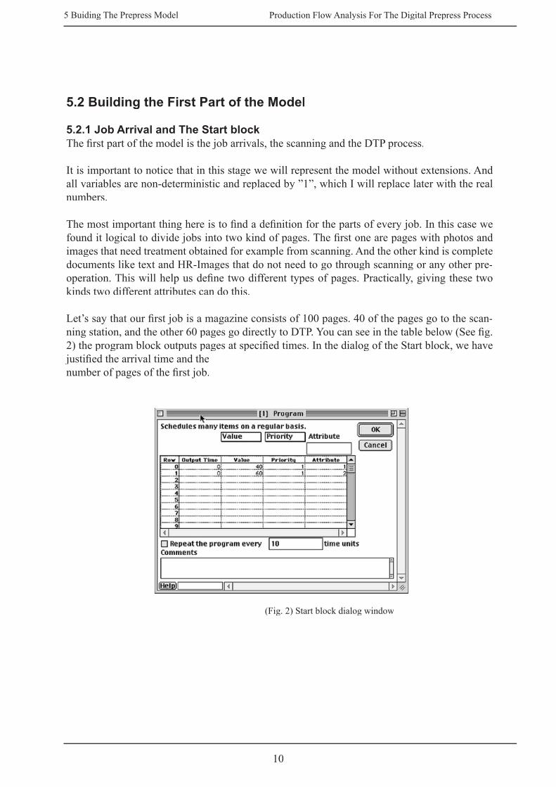
Let’s say that our fi rst job is a magazine consists of 100 pages. 40 of the pages go to the scan-ning station, and the other 60 pages go directly to DTP. You can see in the table below (See fi g. 2) the program block outputs pages at specifi ed times. In the dialog of the Start block, we have justifi ed the arrival time and the number of pages of the fi rst job.
(Fig. 2) Start block dialog window
10

Production Flow Analysis For The Digital Prepress Process5 Buiding The Prepress Model
In the dialog block you can see the following information:
Output Time: The time each batch of pages arrives. In this case is equal to zero if weassume that we have only one job and the pages arrive all at the same time.
Value: The number of pages represented by each page that is output. In our case we have 40-pages will go through scanning, and 60 pages goes directly to DTP.
Priority: The most logical way to justify two types of pages is by giving them a different kind of priority. For example, the priority value “1” is for the 40-pages and priority “2” is for the other 60-pages. This retains that the 40-pages will get treatment in the scanner station before the 60-pages will begin going in into the DTP. This will give the operation a more realistic image and make it more like the real model.
All of the 100 pages go into the Prepress department; they get an attribute and a priority value (See fi g. 2). The pages then will go to the Select block (See fi g. 4) in order to get their different paths, according to their attribute. In the Select DE Output dialog (See fi g. 3), we have deter-mined that the 60-pages will go to the DTP station through the “b” connector and the 40-pages will go to Scanner through the “a” connector.
(Fig.3) Select DE Output dialog choice
11

Production Flow Analysis For The Digital Prepress Process5 Buiding The Prepress Model
5.2.2 The DTP LineThe DTP line is actually consists of two lines that drop in to one end. After the select block, the DTP line divides into a scanner line where pages get scanned and the other line is where the non-scanned pages go. Both lines gathered in the Combine block, which leads to the DTP station (See fi g. 4).
(Fig. 4) The Scanner line and DTP line
Here is a defi nition of the blocks used in this line:
Set Attribute Block: Gives an attribute to the 60-pages. This gives pages with the attribute number “2” a name “non scanning”.
Get Attribute Block: As pages get passed through this block, it will read the attributename “ non scanning “. If an attribute name is found, its value is then reported in the dialog and sent through the output connector.
Combine Block: Combines the pages from fi ve different sources into a single stream. The pages in the Combine Block retain their separate identities and are not batched together.
Buffer Block: Simulates a fi rst-in-fi rst-out (FIFO) queue for buffering pages needed by batching operations. The maximum length, which determines howmany pages the buffer can hold, can be set in the dialog.
DTP Station: Simulates a station operating on a single page for a specifi ed processing or a delay time. When the station is ready, it pulls a page from the buffer and processesit for the time specifi ed. Once a page is processed, it is held until it is picked up by another block. The station is only ready to process the next incoming page when the processed page is taken by another block.
Combine Block: Combines the items from two or more different sources into a single stream of items. This is different from the batch blocks, which join items from several sources into one item. The items in the Combine block retain their separate identities and are not batched together.
12

Production Flow Analysis For The Digital Prepress Process5 Buiding The Prepress Model
5.2.3 The Scanner LineThis line consists of the same kind of blocks as in the DTP line. The 40 pages will fi rst get a name, “Scanner” in the Set Attribute block. If the attribute is found, its value is reported in the Get Attribute block dialog and sent through the output connector. The pages will then go through the buffer block and fi nally though the Scanner blocks where pages get scanned. This line is considered completed as soon as the scanning operation is fi nished. The pages will continue moving through the Combine block to the DTP station and get the same treatment as the other 60 pages.
5.3 Adding an RIP Line to the Model Producing plates is the last operation done in the Prepress department.To complete the basic shape of this model we have to add some more new buffers that represent RIP, montage and plate copying stations.
The new line should look like:
(Fig. 5) The RIP line
The last thing we did in the DTP line is saving all pages as PS-fi les or PDF. As our 100 pages have left the DTP station, they were ready to go through the RIP. Here is a description of the new line:
5.3.1 The RIP LineThis line contains three main stations:
RIP station Montage stationPlate Copying station
Before the RIP station, we have to add a FIFO (fi rst-in-fi rst-out queue bock) Buffer Block to control the fl ow of pages. The pages get into the RIP station then gets color separated and doted to the desired resolution. The pages will then sent further to the other two stations to be pro-cessed and fi nally the pages goes through the Exit block as plates.
13

Production Flow Analysis For The Digital Prepress Process5 Buiding The Prepress Model
(Fig. 6) The RIP line
In fact, the pages will not be put on plates separately and we have to make use of the whole plate area according to the paper format. Suppose that our 100 pages are in A4 format and we will print a full format (Full ark) A1.
There are many kinds of binding styles like:Perfect BoundSadle-StichedCome ’N’ GoCut and Stack
All of these binding styles can be divided into different montages, depending on the page size and the production. In this model we picked “16-pages montage” this includes eight A4 pages on each side of the full size sheet.
The montage will look like something like:
Front Front Front Back
(Fig 7) 16-pages montage
RIP + FILM Mounting
14
Production Flow Analysis For The Digital Prepress Process5 Buiding The Prepress Model
5.4 Adding More Operations to the Model As we put all the parts of the Prepress department together in our model, yet the model is not completed. The next thing we have to do is adding some functions to the model to make it more realistic.
There are two points we would like to explain:After the DTP station the 100 pages do not go directly to the RIP but should go to a station where jobs can be checked to the possibilities of, for example, sending them to proofi ng or not. Proofed pages will be sent to the customer and then get them back, either withsome changes or with approval to printing.
According to this, we have to do some changes in our model; probably a new line and some new buffers.
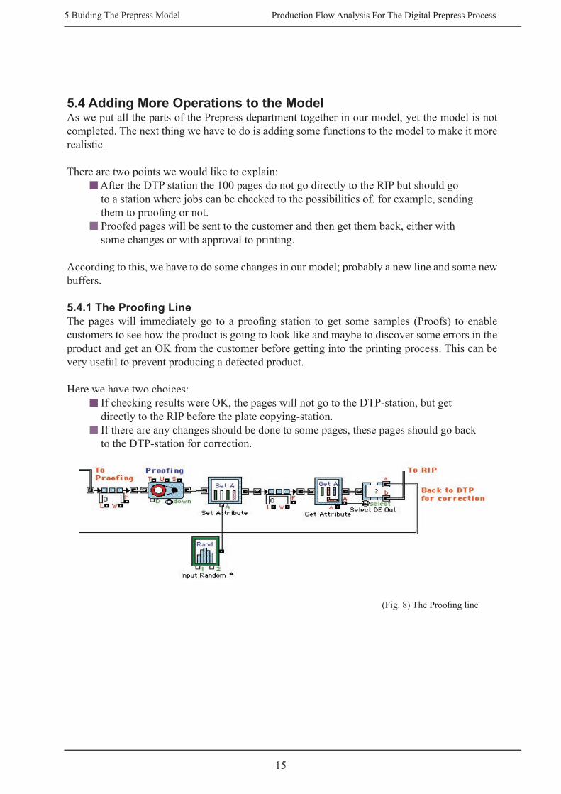
5.4.1 The Proofi ng LineThe pages will immediately go to a proofi ng station to get some samples (Proofs) to enable customers to see how the product is going to look like and maybe to discover some errors in the product and get an OK from the customer before getting into the printing process. This can be very useful to prevent producing a defected product.
Here we have two choices:If checking results were OK, the pages will not go to the DTP-station, but getdirectly to the RIP before the plate copying-station.If there are any changes should be done to some pages, these pages should go back to the DTP-station for correction.
(Fig. 8) The Proofi ng line
15

Production Flow Analysis For The Digital Prepress Process5 Buiding The Prepress Model
In this case we have to insert a choice buffer which would be able to divide pages into two types. The fi rst one we call “OK pages”, and the other would be the “Rejected pages”. This can be done by adding some new blocks like a Set Attribute which defi nes pages and a Get Attribute Block which recognize and justify them to prepare them to choose their different paths.
The new line (See fi g. 8) consists of:
Buffer Block: Simulates a fi rst-in-fi rst-out (FIFO) queue for buffering pagesneeded by batching operations.
Proofi ng station: Simulates a station operating on a single page for a specifi ed processing time.
Set Attribute block: Gives an attribute to the pages a name “Corr” (Correction).
Input Random Block: Generates random integers or real numbers based on the selected distribution. Let’s say that the customer has rejected 30% of input pages. This means that these pages will go back to DTP-station for further treatment or correction. On the other hand, 70% of pages are supposed to be correct and will go directly to RIP (Exit 3 in the Combine block 1, see fi g. 9 and fi g. 12).
(Fig. 9) Input Random Dialog
Get Attribute Block: As pages have passed through the block, the block will read an attribute and that attribute can be specifi ed as the fi rst attribute in the list or a named attribute. If the attribute is found, it s value is reported in the dialog and sent through the output connector. Responded to the Attribute “Corr”.
Select DE Out Block: Selects the input page to be output at one of two output connectors based on a decision. The page at the input is passed through the selected output. The dialog has options for changing the outputs after a given
16
Production Flow Analysis For The Digital Prepress Process5 Buiding The Prepress Model
number of pages have passed and selecting based on the select connector. In this case we have 30% of pages that will go out through “a” output to the RIP line, and 70% goes through the “b” output into the Combine block “1” to be corrected.
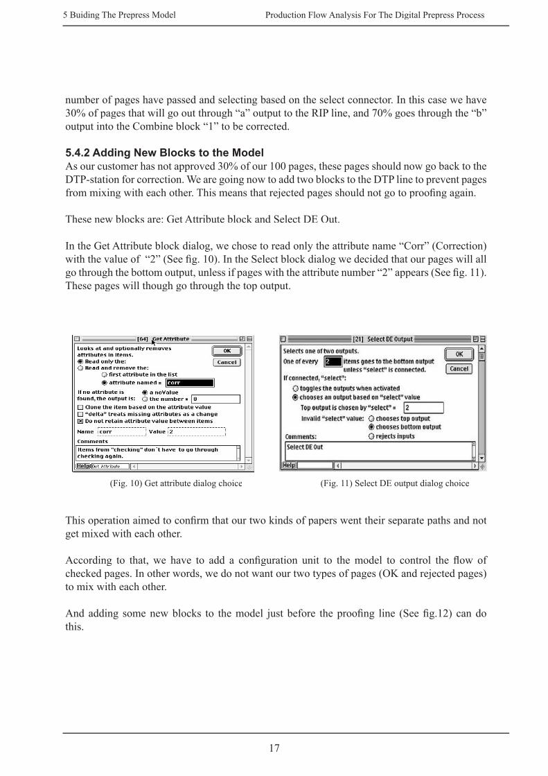
5.4.2 Adding New Blocks to the Model As our customer has not approved 30% of our 100 pages, these pages should now go back to the DTP-station for correction. We are going now to add two blocks to the DTP line to prevent pages from mixing with each other. This means that rejected pages should not go to proofi ng again.
These new blocks are: Get Attribute block and Select DE Out.
In the Get Attribute block dialog, we chose to read only the attribute name “Corr” (Correction) with the value of “2” (See fi g. 10). In the Select block dialog we decided that our pages will all go through the bottom output, unless if pages with the attribute number “2” appears (See fi g. 11). These pages will though go through the top output.
(Fig. 10) Get attribute dialog choice (Fig. 11) Select DE output dialog choice
This operation aimed to confi rm that our two kinds of papers went their separate paths and not get mixed with each other.
According to that, we have to add a confi guration unit to the model to control the fl ow of checked pages. In other words, we do not want our two types of pages (OK and rejected pages) to mix with each other.
And adding some new blocks to the model just before the proofi ng line (See fi g.12) can do this.
17

Production Flow Analysis For The Digital Prepress Process5 Buiding The Prepress Model
(Fig.12) The Prepress model after confi guration
The new confi guration consists of:
Set Attribute Block: Set attribute value “1” if page needs checking and attribute value “0” if it is not.
Input Random Block: Generates random integers or real numbers based on the selected distribution. You can use the dialog or the two inputs, “1” and “2” to specify arguments for the distributions. You can select the type of distribution: Uniform (integer or real), Binomial, Erlang, Expo nential, Hyper Exponential, Log Normal, Normal, Poisson, Triangular, Weibull, and General. The General distribution uses a table of up to 50values to generate a discrete, stepped, or interpolated general distribution. In our case only 10% goes to proofi ng, 90% do not need to, but goes directly to plate copying.
A fi rst-in-fi rst-out (FIFO) Queue: The maximum length, which determines how many pages the queue can hold, can be set in the dialog. You can specify that the simulation should stop when the queue is full (reaches the maxim length). You can also see the average queue length, average wait time, and utilization of the queue in the dialog.
Get Attribute Block: As pages are passed through the block, the block will read an attribute and that attribute can be specifi ed as the fi rst attribute in the list or a named attribute. If the attribute is found, its value is reported in the dialog and sent through the output connector.
RIP + FILM Mounting
18

Production Flow Analysis For The Digital Prepress Process5 Buiding The Prepress Model
5.5 Adding Plotter Blocks to the ModelPlotter, Discrete Event gives plot and tables of data for up to four value inputs in discrete event models. Both the value and the time the value was recorded are shown in the data table for each input. In the dialog it is possible to specify whether to plot values only when they change.
There are many kinds of plotter in Extend. The choice of plotter depends on the type of model, whether it is a continuous or discrete event, and how we want the information plotted. The plot-ter window has two panes (See fi g. 13). The upper pane shows the plot (one or more traces) and the lower shows the data points, which produce the line.
(Fig. 13) Plotter window
To this model we added three plotters each one represent the results of one operation compared to the input information in the input block.
The fi rst plotter “Plotter 1” is associated to the scanner line (See fi g. 14). The upper input connector is connected to the start block through the “V” output.The second input is connected to the buffer block in the scanner line through the “L” connector. This is used to show the number of pages in the buffer.The third input is connected with the “W” connector in the same buffer block and it is used to show the waiting time for pages leaving the buffer.
19

Production Flow Analysis For The Digital Prepress Process5 Buiding The Prepress Model
The second plotter “Plotter 2” is addicted to the DTP line with the same instructions. The only difference is that the last input is connected with the Exit block to show the number of sheets leaving the Prepress.
The third plotter “Plotter 3” scales the results in the RIP line.
(Fig. 14) Adding three plotter blocks to the model
MountingRIP + FILM
20

Production Flow Analysis For The Digital Prepress Process6 Results
6.1 Analyzing the Model and Running the SimulationOnce the model is built it, has to be tested and analyzed. In this chapter we are going to run the model, examine its performance, and then analyze the results to determine whether the model is behaving as the real system or not. This process is known as the model verifi cation and validation could be termed (reducing to the absurd) since we reduce a complex model to an aggressively simple case so that we can easily predict what the outcome will be.
6.1.1 Model Verifi cationVerifi cation is the process of ensuring that a model behaves as expected. We have already per-formed a part of the verifi cation process by building the model in stages and with minimal detail, then running it at each stage to observe the results.
A simple verifi cation technique is to make sure that we can account for all pages in the model. For example, we could calculate the numbers of papers we are expecting to receive and see if that number corresponds to the arrivals in the Input block.
The certain things we want to do now is to verify our model by:
Removing all the variability from the model and making it deterministic. This is already done by assuming that all the variables in the model are equal to “1”.
Running the deterministic model twice or more to make sure that we get the same results. The result should show the same number as in the input every time we run the model.
As we mentioned before, our job consists of totally 100 pages and this is what we used in the fi rst runs. The output value actually confi rms to the input value which means that the model is working proportionately. We can clearly see the output value in the buffer block before the RIP station in the RIP line (See fi g. 12). As the dialog window shows (fi g. 15), the arrival pages are exactly one hundred and the same number leaves the buffer to the RIP station. The pages go then to the Batch (Variable) block where pages put into a 16-pages montage. This means that the number “100” is simply divided by eight (8 pages per sheet). The result should be totally twelve sheets or plates and this we can see clearly in the Exit block dialog in the RIP line (See fi g. 15). Notice here that all the variables are still equal to one. This includes even the number of stations and workers.
21
6 RESULTS

Production Flow Analysis For The Digital Prepress Process6 Results
(Fig. 15) The output value (to the right) corresponding to the input
Output detailed reports or traces to see whether the results meet our expectations or not. The certain thing we ought to do is checking all the different parts of the model and run the simulation for each part separately. This allows us to determine whether these parts are working properly and if all the parts are functioning as planned. As the simulation result shows (fi g. 16), the number of pages, for example in the Scanner station is 40 pages exactlly as in the Start block dialog (Please refere to fi g. 2, page 10).
(Fig. 16) The Scanner station dialog window
As we know, the 40-pages should go to the Scanner line fi rst before the other 60-pages should reach the DTP line. To control this, we put two more blocks to the model. These blocks are called “Accumulate block”, (See fi g. 17). This block adds up the values at the input connector from each step or event and shows the total contents at the output connector. It also shows a level, which rises and falls, represents an animation of the contents of the block at each step/event. The blocks clearly show the arrival of pages into the Scanner station and the DTP station and how the fi rst Accumulate, which is connected to the Scanner station is getting full loaded before the other block which is connected to the DTP station.
22

Production Flow Analysis For The Digital Prepress Process6 Results
(Fig. 17) The Accumulate blocks
Running a schedule of only one product line as opposed to several. This is very important to under-stand the system and see how the model performs under different conditions. This enables us to detect the bottlenecks and the weak spots in the system. Reducing the number of workers to 1 or 0 to see what happens. The model shows that the waiting time increases when we reduce the number of workers or stations. Take the scanner station for example, the waiting time (as fi gure 18 shows) is about the double when we reduce the number of scanners from two to one. In the dialog choice we can see the average wait in the dialog to the right is “9.366” when we put two scanners in order. This number raises drastically as soon as we reduce the number of scanners to one scanner. As you can see in the fi gure to the right, the average time is “19.5”. You can even see the difference between the Max queue length and Max wait.
(Fig. 18) The difference in wait time between two cases
23

Production Flow Analysis For The Digital Prepress Process6 Results
6.1.2 Model ValidationOnce the model is verifi ed, we need to validate it to determine if it accurately represents the real system. This does not mean that the model should confi rm to the real system in every aspect. Instead, a valid model is a reasonably accurate representation based on the model’s intended purpose. When validating, it is important to make sure to know what to compare to and to verify that measures are calculated in the same manner.
For validation, the model should accurately represent the data that was gathered and the assump-tions that were made regarding how the system operates. In addition, the underlying structure of the model should correspond to the actual system and the output statistics should appear reason-able. While it is normally to compare critical performance measures, it is also sometimes helpful to compare nonessential results, which may be therefore show, the character of the system.
One of the best validation measures is “Does the model make sense?” Other involves obtaining approval of the results that familiar with the actual process and comparing simulation results with historical data.
In order to test out model, we have to create a job and insert some data into it.
Here is a description of the job that we are going to use in this case:
A 100-page calendar, where 10 pages contain images that will be scanned and the rest of the pages contain only text.
The page format is “A5” (this is very important to know when creating sheet layout).The pages will be put in a 32-page layout. The Calendar cover contains the fi rst and the last two pages of the 100 pages (pages No. 1, 2, 99, 100). The petition will includethe rest of the 96 pages. These 96 pages will be put into the 32-Montage and will create “6” fl ats of them and “2” more of the cover. That will be totally “8” fl ats.
Almost all the moments in this job will be done digitally. This includes creating the sheet layout and proofi ng. The fi rst thing to do is moving the Demand block, whichmerge in pages into our montage, in front of the Montage station, and then move theMontage block forward as well (See fi g. 20). The result is that we have the montage station before the RIP station.
24

Production Flow Analysis For The Digital Prepress Process6 Results
(Fig. 20) Adjusting the model according to our product
Here are some statistic numbers we managed to collect during visits to some of the Prepress / Repro companies. Though these numbers were measured in different ways it not certain that they represent the actual system, so the most logical solution is to take the average of these numbers and insert them in our model and observe the results.
Scanning (0.083) h [5 min/ page]DTP DTP DTP (0.1) h [6 min/ page]Creating Layout (digital) (1) hRIP RIP RIP (1.2) h [RIP=8 min + Developing=2 min/graphic fi lm * 4 colors * 8 fl ats]
Plate Copy (Exposing & Developing plates) (3.04) h [5,7 min/ plate]Proofi ng (digital) (0.83) h [only some pages (10) will get High Quality proofed, the rest of the pages will get printed in a plotter writer as complete fl ats. It takes “3” A3 papers to write the “10” pages and (0.13 h). And (0.7 h) for the rest]
Complete Model
25

Production Flow Analysis For The Digital Prepress Process6 Results
After running the simulation several times the following results was scored:
The Scanner line:The Buffer window shows these results: Pages in the Buffer 10 PagesAverage wait 0.3735 hrMax length 10 PagesMax wait 0.747 hr
(Fig 21) The Scanner Buffer window
(Fig 22) Plotter window diagram for the scanner station
As the diagram shows (fi g. 22), when the input 10 pages arrive the max queue length in the buffer is also 10. This number decreases as soon as the scanner station begins processing the pages. The max wait in this case reaches “0.747” hr. The average wait is 0.3735 hr, which points out that the scan-ner station is working properly and there are no bottlenecks discovered in this stage for this particular job.
26

Production Flow Analysis For The Digital Prepress Process6 Results
The DTP line:The Buffer window shows these results: Pages in the Buffer 103 PagesAverage wait 4.7754 hrMax length 91 PagesMax wait 9.07 hr
(Fig 23) The DTP Buffer window
(Fig 24) Plotter window diagram for the DTP station
The max queue length in this station is “91” pages of “103” and diminishes after Max “9.07” hr. This can only mean that we have an obvious bottleneck here. In fact, this can look much worse if the station gets more jobs or even if a more complicated job arrives.
27

Production Flow Analysis For The Digital Prepress Process6 Results
The RIP line:The Buffer window shows these results: Pages in the Buffer Pages in the Buffer Pages in the Buffer 100 PagesAverage wait 1.5098 hrMax length 24 PagesMax wait 2.9 hr
(Fig 25) The RIP Buffer window
(Fig 26) Plotter window diagram for the Rip station
“12” fl ats goes into the RIP station and the max wait is “2.2” fl ats. This looks really good compared to the other stations.
28

Production Flow Analysis For The Digital Prepress Process7 Discussion & Recommendations
Perhaps the only concern we can think of in this model is the DTP station, because of the obvious bottleneck that appeared when we ran the simulation. Note here that there was only one single job involved with this model. What if the station gets more jobs, and even complicated ones. Increasing the number of people in the DTP line can defi nitely solve the problem. Getting more DTP stations can reduce the possibilities of having a bottleneck in this line. But the question is, is this really enough to take us to the safe side? Well, in some cases maybe it is fare enough. However, we should be certain of the results and should make sure that the prepress department would not get into diffi cult situations by loosing the ability to deliver jobs to other departments where this will defi nitely brake the chain of production.
In the past 20 years, we witnessed a huge development in the digital technology and personal computers that delivered new facilities and equipment. This effected all fi elds and businesses, including the DTP and prepress business. This has actually eliminated the need for the old generation of both machines and workers. This may also leads us to the conclusion that these companies will not be able to survive the new age unless they consider doing some investments to develop and upgrade their equipment and staff.
We can see potential problems today in many companies that are not really mature for taking further step into this new world of possibilities. Some of these companies are only adapting some parts of total solutions, which actually purvey new problems and makes it more diffi cult for them to keep the system working as it should be.
During my visits to the pilot companies that involved with this study, I witnessed that the major-ity of these companies were still using the conventional way of creating montages and graphic fi lms. A certain Image Setter provides pieces of fi lms to a group of people called the Montage Group that consists of no less than 3 people, depending on the size of the company. Their duty is to create montages on graphic fi lm by cutting parts manually from the fi lm that was delivered by the Image Setter and pasting them to a new montage that suits the printing plates according to the printer standards.
Today, the CTP (Computer-To-Plate) technology has become so advanced that it enabled com-panies to revolutionarily reduce time, costs and efforts. With the help of certain software, we can nowadays do our montages on the PC. This process involve sending the fi nal fl at as a fi le to another computer which contains the RIP (Raster Image Processor) for processing information to a matrix of dots, and then sends this information to the Image Setter which prints it on plates or fi lms.While it takes many hours to deliver plates using the old technology, it takes only few minutes using the CTP technology, which are ready to go directly to the printer. Nevertheless the amount of money the company is spending on materials and labor. Also, never mention the huge differ-ence in quality. Note here that the technology used in this model is CTP, otherwise it is possible to have a bottleneck in this line as well.
The same discussion goes for the other parts of the model. For example, a photo was scanned in an old AGFA scanner took about 8 minutes before the digital fi le was delivered to the DTP station, while a similar photo took only 2 minutes when using a
29
7 DISCUSSION & RECOMMENDATIONS

Production Flow Analysis For The Digital Prepress Process7 Discussion & Recommendations
modern Heidelberg scanner, and of course with much better quality. This was actually measured on a single photo. What if we have several of photos in the buffer? Besides, we do not often get good quality photos with the job, old and bad quality images that need lots of treatment after scanning. This also leads us to the necessity of having some professional equipment that can secure our production fl ow and skilled people with the necessary training.
Simulation models can describe the real system to some level of similarity (not up to 100 per-cent). These models can illustrate how the real system works and how the system performs under different conditions. However, it can not tell us how to rearrange the conditions to optimize the system.There are many ways to classify simulation models, like whether or not the model has a stochas-tic (or random) aspect. Deterministic simulations are completely defi ned by the model. Rerun-ning a simulation will not change the outcome. Stochastic simulations include randomness. Multiple runs of the same model may generate different values. This random element forces us to generate many outcomes to see the range of possibilities. The question of whether to generate 10 or 1,000 or 100,000 outcomes is primarily a statistical question. Simulations with random elements require sophisticated statistical analysis.
30
Production Flow Analysis For The Digital Prepress Process
8 REFERENCES
[1] Extend usesrs guid Imagine That, Inc.
[2] Advanced System Modeling and Simulation With Block Diagram LanguagesNicholas M. Karayanakis CRC Press - June 9, 1995
[3] Computers: Inside and OutKurt F. Lauckner & Mildred G. Lintner Pippin Publishing - January 1996
[4] Enabling Systemic Business Change -- Integrated Methods and Software Tools for BPRVolker Bach, Brecht, Hess, Osterle Friedrich Vieweg & Sohn - June 1996
[5] Improve Quality and Productivity with SimulationThomas J. Gogg & Jack R.A. Mott, C.P.A., M.B.A. JMI Consulting Group - December 1996
[6] Simulation Based Engineering of Complex SystemsJohn R. Clymer, Ph.D.
[7] SimulationstechnikDr. Ulrich Kramer & Dr. Mihaela Neculau Fachhochschule Bielefeld September 1998
31