productıon of carbon nanotubes by cvd
TRANSCRIPT

PRODUCTION OF ALUMINA BOROSILICATE CERAMIC NANOFIBERS BY USING ELECTROSPINNING TECHNIQUE AND
ITS CHARACTERIZATION
A THESIS SUBMITTED TO THE GRADUATE SCHOOL OF NATURAL AND APPLIED SCIENCES
OF MIDDLE EAST TECHNICAL UNIVERSITY
BY
SENEM TANRIVERDİ
IN PARTIAL FULFILLMENT OF THE REQUIREMENTS FOR
THE DEGREE OF MASTER OF SCIENCE IN
CHEMICAL ENGINEERING
JUNE 2006

Approval of the Graduate School of Natural and Applied Sciences
Prof. Dr. Canan Özgen Director
I certify that this thesis satisfies all the requirements as a thesis for the degree of Master of Science.
Prof. Dr. Nurcan Baç Head of Department
This is to certify that we have read this thesis and that in our opinion it is fully adequate, in scope and quality, as a thesis and for the degree of Master of Science.
Prof. Dr. Üner Çolak Co-Supervisor Prof. Dr. Güngör Gündüz
Supervisor
Examining Committee Members
Prof. Dr. Deniz Üner (METU, CHE)
Prof. Dr. Güngör Gündüz (METU, CHE)
Prof. Dr. Üner Çolak (HU., NEM)
Assoc. Prof. Dr. Gürkan Karakaş (METU, CHE)
Ph. D. Bora Maviş (HU., IE)

GIARISM I hereby declare that all information in this document has been obtained and presented in accordance with academic rules and ethical conduct. I also declare that, as required by these rules and conduct, I have fully cited and referenced all material and results that are not original to this work. Name, Last name : Senem Tanrıverdi Signature :
iii

ABSTRACT
PRODUCTION OF ALUMINA BOROSILICATE CERAMIC
NANOFIBERS USING ELECTROSPINNING TECHNIQUE AND
ITS CHARACTERIZATION
Tanrıverdi, Senem
M.S., Department of Chemical Engineering
Supervisor: Güngör Gündüz, Prof. Dr.
Co-Supervisor: Üner Çolak, Prof. Dr.
June 2006, 71 pages
Today, ceramic, polymer, and composite nanofibers are among
the most charming materials for nanotechnology. Because of their
small characteristic dimension, high surface area, and microstructural
features, they provide unique mechanical, optical, electronic, magnetic,
and chemical properties for an extensive variety of materials
applications.
Electrospinning provides an effective way of the nanofiber
production in a nanometer scale. This technique utilizes a high voltage
DC to create a strong electric field and a certain charge density in a
viscous solution contained in a pipette. As a result, fibers with
iv

diameters ranging from the micrometer to nanometer are formed from
this charged solution.
This study deals with, the fabrication of alumina borosilicate
ceramic nanofibers using electrospinning technique. Alumina
borosilicates contain important components having intriguing
characteristics for many applications and have been widely studied
with different compositions.
In this study, alumina borosilicate/PVA solution was prepared
using the conventional sol-gel method. Polyvinyl alcohol (PVA) was
added into this solution to increase the viscosity for electrospinning.
After the alumina borosilicate/PVA solution was electrospun into fibers,
high temperature sintering was carried to obtain ceramic alumina
borosilicate fibers. The products were characterized by scanning
electron microscopy (SEM), X-ray diffractometry (XRD), Fourier
transform-infrared spectroscopy (FT-IR), and
thermogravimetric/differential thermal analysis (TG-DTA) techniques.
Keywords: alumina borosilicate, ceramic nanofibers, sol-gel,
electrospinning, nanotechnology.
v

ÖZ
ELEKTROSPİNLEME YÖNTEMİYLE ALUMİNA BOROSİLİKAT
SERAMİK NANOELYAFLARIN ÜRETİMİ VE ÖZELLİKLERİNİN
BELİRLENMESİ
Tanrıverdi, Senem
Yüksek Lisans, Kimya Mühendisliği Bölümü
Danışman: Güngör Gündüz, Prof. Dr.
Yardımcı Danışman: Üner Çolak, Prof. Dr.
Haziran 2006, 71 sayfa
Günümüzde seramik, polimer ve kompozit nanoelyaflar
nanoteknolojinin en cazip ürünleri arasındadır. Boyutlarının küçük,
yüzey alanının büyük olmasından dolayı, çeşitli uygulamalar için eşsiz
mekanik, optik, elektronik, manyetik ve kimyasal özellikler sağlarlar.
Elektrospinleme tekniği, son zamanlarda nano boyutta elyaf
üretimi için sıkça kullanılmaktadır. Elektrospinleme işleminde, içinde
çözelti bulunan kapiler uca sahip bir hazne ile metalik malzemeden
yapılmış ve fiberlerin toplanmasında kullanılan toplama yüzeyi
arasında yüksek bir elektrik alan oluşturulur. Voltaj kritik bir seviyeye
ulaşınca, kapiler ucunda askıda duran damlacık yüzeyinde oluşan yük,
vi

yüzey gerilimini yenerek bir jet oluşumuna neden olur. Elektriksel
olarak yüklü jet, yarılarak ya da esneme hareketleriyle incelerek
toplama yüzeyinde dağınık olarak toplanır.
Bu çalışmada, elektrospinleme yöntemiyle alumina borosilikat
seramik nanoelyaf üretimi gerçekteştirilmiştir. Alumina borosilikatlar,
yapısında birçok uygulama için ilgi çekici özelliklere sahip bileşenler
içerir ve şu ana kadar, farklı bileşimlerde yapılmış çalışmaları yaygın
olarak bilimsel kaynaklarda bulunmaktadır.
Elektrospinleme tekniği ile alumina borosilikat elyaf üretimi için
gereken çözeltinin hazırlanmasında çöz-pel (sol-gel) yöntemi
kullanılmıştır. Hazırlanan çözeltinin viskozitesini ayarlayabilmek için
polivinil alkol (PVA) katılmış ve ardından çözelti spinlenmiştir.
Oluşan alumina borosilikat/PVA içerikli elyaflar yüksek
sıcaklarda sinterlendikten sonra alumina borosilikat elyaflar elde
edilmiştir. Taramalı elektron mikroskopu (SEM), X-ışını kırınımı (XRD),
Fourier dönüşümlü kızılötesi spektrumu (FT-IR), termogravimetrik ve
diferansiyel termal analiz (TG-DTA) teknikleri kulanılarak ürünün
özellikleri belirlenmiştir..
Anahtar Sözcükler: alümina borosilikat, seramik nanoelyaflar, çöz-pel
elektrospinleme, nanoteknoloji.
vii

To My Exceptional Family
viii

ACKNOWLEDGEMENTS
I would like to express my sincere gratitude to Prof. Dr. Güngör
Gündüz for accepting me as my supervisor and for giving me such
opportunities to fulfill this research. Additionally, I would like to thank
my co-supervisor Prof. Dr. Uner Çolak for helping me on many
occasions.
I would like to acknowledge Bora Maviş for his ideas and benefit
to push this study further.
I would also like to thank Cengiz Tan and Nedret Özkar for their
helps in characterization studies, Çiğdem Platsu for her help supplying
the chemicals and equipment and the technicians of the machine shop
for their helps.
I acknowledge with thanks the support of TÜBİTAK (The Science
and Technical Research Council of Turkey)-MAG (Engineering
Research Group).
I would like to give my most special thanks to my family, for
being patient and understanding throughout my education period and
for supporting me in whatever decision I’ve made.
Last but not least, I would like to thank all of my friends for all
their emotional support and motivation during this extremely difficult
accomplishment.
ix

TABLE OF CONTENTS
PLAGIARISM....................................................................................... iii
ABSTRACT ......................................................................................... iv
ÖZ........................................................................................................ iv
DEDICATION .....................................................................................viii
ACKNOWLEDGEMENTS ................................................................... ix
TABLE OF CONTENTS ....................................................................... x
LIST OF TABLES ...............................................................................xiii
LIST OF FIGURES............................................................................ xiv
NOMENCLATURE ............................................................................xvii
CHAPTER
1. INTRODUCTION...........................................................................1
2. LITERATURE SURVEY................................................................4
2.1 Electrospinning ....................................................................4
2.1.1 Fundamental Principles.................................................4
2.1.2 Electrospinning Process................................................7
2.1.2.1 Schematic Setup of Electrospinning Electrospinning
……………………………………………………………………...8
2.1.2.2 Electrospinning Stages………………………………….9
2.1.2.2.1 Jet Initiation………………………………………9
x

2.1.2.2.2 Jet Thinning……………………………………..11
2.1.2.2.3 Solidification of the jet….………………………13
2.1.3 Nanofiber Materials .. …………………………………..13
2.2 The Sol-Gel Chemistry .....................................................18
2.2.1 Catalyst Effect ..........................................................21
2.2.2 Reactivity of various metal alkoxides .............................21
2.2.3 Influence of water ....................................................22
2.2.4 Influence of solvent..................................................22
2.2.5 Advantages of Sol-Gel Processing..........................23
2.2.6 Limitations of Sol-Gel Processing............................24
2.3 Formation Of Multicomponent Oxides...............................25
2.4 Alumina Borosilicate Ceramic Systems.............................26
3. EXPERIMENTAL ........................................................................28
3.1 Introduction........................................................................28
3.2 Raw Materials....................................................................28
3.3 Sol Preparation..................................................................29
3.4 Electrospinning..................................................................34
3.5 Heat Treatment..................................................................35
3.6 Parameter Examined ........................................................35
3.7 Chemical Characterization................................................35
3.7.1 Fourier Transform Infrared (FTIR) Spectroscopy.........35
3.7.2 Scanning Electron Microscopy (SEM)..........................35
xi

3.7.3 X-Ray Diffraction (XRD) ...............................................36
3.7.4 Differential Thermal/Thermogravimetric Analysis
(DTA/TG ................................................................................36
4. RESULTS AND DISCUSSION....................................................37
4.1 Preliminary Experimental Results......................................37
4.2 Parametric Studies ............................................................43
4.2.1 Effects of Viscosity and Solvent ...................................43
4.2.2 Effect of Applied Electric Voltage .................................46
4.2.3 Effect of Tip-to-Collector Distance................................47
4.3 Sintering Effects.................................................................49
4.4 Fourier Transform Infrared (FT-IR) ....................................55
4.5 X-Ray Diffraction (XRD).....................................................57
4.6 Differential Thermal and Thermogravimetric Analysis
(DTA/TG) .....................................................................................59
5. CONCLUSIONS..........................................................................61
RECOMMENDATIONS ......................................................................63
REFERENCES...................................................................................64
xii

LIST OF TABLES
Table
2.1 Examples of electrospun polymers..................................... 13
2.2 Ceramics that have been electrospun ................................ 17
3.1 Properties of the raw materials ........................................... 29
3.2 Compositions of electrospinning solution #1 ...................... 32
3.3 Compositions of electrospinning solution #2 ...................... 32
3.4 Compositions of electrospinning solution #3 ...................... 32
4.1 Viscosities of three different electrospinning solutions ........ 43
4.2 Fibers diameters of various samples electrospun at 8,
10, 12 and 15 kV applied electric voltage ........................... 47
4.3 Fibers diameters of various samples electrospun at 7,
10, and 15 cm tip-to-collector distance .............................. 47
xiii

LIST OF FIGURES
Figure
2.1 The mechanism of the droplet explosion .............................. 7
2.2 A typical experimental setup of the electrospinning
process ...................................................................................
.............................................................................................. 9
2.3 Schematic of the forces on a droplet at the tip of the
pipette ................................................................................ 11
2. 4 Sol-Gel Process .................................................................. 20
3.1 Flow chart of the synthesis of the Alumina borosilicate
ceramic nanofibers.............................................................. 31
3.2 Electrospinning System ...................................................... 34
4.1 SEM micrographs of aluminum borosilicate/PVA
electrospun fibers prepared by using aluminum
ethoxide and toluene........................................................... 38
4.1 (contd’) SEM micrographs of aluminum
borosilicate/PVA electrospun fibers prepared by using
aluminum ethoxide and toluene.......................................... 39
xiv

4.2 SEM micrographs of aluminum borosilicate/PVA fibers
prepared by using aluminum isopropoxide and isopropyl
alcohol................................................................................. 41
4.2 (contd’) SEM micrographs of aluminum
borosilicate/PVA fibers prepared by using aluminum
isopropoxide and isopropyl alcohol..................................... 42
4.3 SEM micrographs of PVA/alumina borosilicate fibers
electrospun from solution with viscosity of 2.42 poise
(Electrospinning solution #1)............................................... 44
4.4 SEM micrographs of PVA/alumina borosilicate fibers
electrospun from solution with viscosity of 6.5 poise
(Electrospinning solution #2)............................................... 45
4.5 SEM micrographs of PVA/alumina borosilicate fibers
electrospun from solution with viscosity of 4.6 poise
(Electrospinning solution #3)............................................... 45
4.6 SEM micrographs of PVA/alumina borosilicate fibers
electrospun at 15cm tip-to-collector distance and
various electric voltages: (a) 8 kV; (b) 10 kV; (c) 12 kV;
(d) 15 kV. ................................................................................
............................................................................................ 46
4.7 SEM micrographs of PVA/alumina borosilicate fibers
electrospun at 10kV electric voltage and various tip-to-
collector distances: (a) 7cm; (b) 10 cm; (c) 15cm. ............ 48
xv

4.8 SEM micrographs of alumina borosilicate/PVA
composite fibers
............................................................................................ 50
4.9 Frequency distribution for fibers: (a) dried at 70°C (b)
sintered at 800°C. ............................................................... 51
4.10 SEM micrographs of alumina borosilicate fibers
sintered at 800°C ............................................................... 52
4.11 SEM micrographs of alumina borosilicate fibers
sintered at 1000°C ............................................................. 53
4.12 SEM micrographs of alumina borosilicate fibers
sintered at 1200°C ............................................................. 54
4.13 FT-IR spectra of various fiber samples: (a) As-dried at
70°C alumina-borosilicate/PVA composite fibers; (b)
sintered at 800°C; (c) sintered at 1000°C. .......................... 56
4.14 XRD results of various fiber samples: (a) As-dried at
70°C alumina-borosilicate/PVA composite fibers; (b)
sintered at 800°C; (c) sintered at 1000°C ........................... 58
4.15 TG-DTA curves of precusor fibers of alumina
borosilicate/PVA fibers........................................................ 60
xvi

NOMENCLATURE
Ao Amstrong
cm Centimeter
C Celcius
gr Gram
k Kilo
µ Micron
mm Millimeter
nm Nanometer
V volt
δ Partial Charge
oε Dielectric Permeability Of Free Space
Fe Coulombic Repulsion Force
γ Surface Tension
H Tip-to-Collector Distance
L Length of the Capillary
n Coordination Number
Q Droplet Charge
λ Wavelength
R Radius
θ Theta
Vc Critical Voltage
X Fissility
z Oxidation State
xvii

EtOH Ethanol
FT-IR Fourier Transform-Infrared Spectroscopy
i-PrOH Isopropyl Alcohol
M Metal
PVA Poly Vinyl Alcohol
PVAc Poly Vinyl Acetate
SEM Scanning Electron Microscope
TEOS Tetra Ethoxy Orthosilicate
TG-DTA Thermogravimetric/Differential Thermal Analysis XRD X-Ray Diffractometry
xviii

CHAPTER 1
INTRODUCTION
Nanotechnology is nowadays a popular interdisciplinary field
including many areas such as mechanics, electronics, optics, biology,
medicine, and material science. “Nanotechnology” is the application of
science to build the new materials or devices by manipulating and
working with atoms and molecules down on the scale. The “nano” in
nanotechnology means one billionth that is about 10,000 times smaller
than the diameter of a human hair.
American physicist and Nobel Prize winner, Richard Feynman is
accounted as the inspirational father of nanotechnology for introducing
the idea of molecular manufacturing, in a lecture, “There is Plenty of
Room at the Bottom” [1] in 1959. However, the origins of
nanotechnology did not occur until then. He attracted his audience’s
attention suggesting that what if one could build materials and devices
with manipulating and controlling them at the molecular level.
In 1974, Norio Taniguchi introduced the term “nanotechnology”
to represent extra-high precision and ultra-fine dimensions, and also
predicted improvements in integrated circuits, optoelectronic devices,
mechanical devices, and computer memory devices. This is the so-
called ‘top-down approach’ of carving small things from large
1

structures. In 1986, K. Eric Drexler in his book “Engines of Creation”
discussed the future of nanotechnology, particularly the creation of
larger objects from their atomic and molecular components, the so-
called “bottom-up approach”. He proposed ideas for “molecular
nanotechnology”, which is to produce any kind of object from elemental
particles. [2]
Today, ceramic, polymer, and composite nanofibers and
nanotubes are the most charming materials for nanotechnology.
Because of their small characteristic dimension, high surface area, and
microstructural features, they provide unique mechanical, optical,
electronic, magnetic, and chemical properties for a wide variety of
materials and applications. They are mostly produced by synthetic
bottom-up methods resulting as discontinuous fibers. However, this
method leads to difficulties with their alignment, assembly, and
processing into applications. It is seen that continuous fibers provide
easy alignment, assembly and processing because of superior
mechanical properties (e.g., strength, stiffness etc.) and continuity of
fibers. That’s why; there is a considerable interest in producing
continuous fibers at nanoscale. “Electrospinning” as a top-down
method makes possible the production of continuous and very narrow
diameter range (10-1000nm) fibers efficiently. In the electrospinning
process, there are two major components: a high voltage DC power
supplier, a capillary tube with a small diameter, and a metal collection
system. High voltage power supplier produces a high voltage electric
field between an oppositely charged solution contained in a pipette and
metallic collection screen. When the voltage attains a critical value, the
suspended solution with hemi-spherical surface formed on the tip of
the pipette ejects a charged jet. As the charged jets are spun, the
2

fibers are collected as a randomly oriented, nonwoven mat on the
surface of the metal collector.
A number of polymer nanofibers have been electrospun directly
from polymer solutions or melt [3-10]. Recent studies demonstrate that
ceramic and ceramic/ polymer composite nanofibers are also prepared
with electrospinning using conventional sol-gel method, followed by a
high-temperature pyrolysis [11-32]. The outcome of ceramic nanofiber
studies will be utilized in many areas in the future, for example,
nanostructured membranes for filtration and separation, reinforcement
materials for nanocomposites, supports for nanostructured catalysts,
and electrode materials for energy conversion or storage.
In this study alumina borosilicate/PVA composite nanofibers in
composition of 0.8 SiO2. 0.1 Al2O3 .0.1B2O3 were prepared using sol-
gel method and electrospinning technique and characterized using
SEM, XRD, FT-IR and DTA/TG techniques.
3

CHAPTER 2
LITERATURE SURVEY
In this part, the principles of electrospinning are presented with reviews
of some polymeric and ceramic nanofiber materials published in
literature. Also, conventional sol-gel method, which is used for the
preparation of ceramic nanofibers via electrospinning, is explained.
2.1 Electrospinning
2.1.1 Fundamental Principles
English physicist Lord Rayleigh introduced the foundations of
electrospinning, at the end of the 19th century. He studied theoretical
behavior of isolated charged water droplets in thunderstorm cloud.
There are two forces that influence a droplet: the Coulombic repulsion
force (Fe) and the surface tension (γ) that give the droplet a spherical
shape. Lord Rayleigh suggested that, at “Rayleigh limit” [33] these
forces are equal and the system is stable.
Rayleigh Limit:
18
Q X3
o
==Rγεπ
(1)
4

Where is the droplet charge, Q R is the droplet radius, γ is bulk liquid
surface tension, oε is the dielectric permeability of free space, and X is
“fissility”. As shown in Figure 2.1, when the solvent evaporates, the
net charge density on the surface will increase and finally the
electrostatic Coulomb repulsion forces become sufficient to overcome
the stabilizing effect of the surface tension that holds the droplet
together, the droplet becomes unstable and explodes into smaller
droplets of equal charge. In other words when X>>1, an instability
occurs and "the liquid is thrown out in fine jets, whose fineness,
however, has a limit" [33]. Rayleigh’s explosion study illuminated
evolution of “electrospraying phenomenon (or electrostatic
atomization)” which is the origin of fundamental principle of
“electrospinning phenomenon”.
Zeleny [34] studied the surface behavior of a charged droplet and
demonstrated the effect of strong electrical potential applied to a small
capillary tube, which induces the eventual break-up of jet from the
droplet. Vonnegut and Neubauer [35] proved that it was possible to
produce monodisperse particles below 1 micrometer from a pending
droplet by the electrospraying technique. In the 1960s, Sir Geoffrey
Taylor [36] obtained the critical electrical potential needed for the
formation of a jet transformed from the droplet at the tip of a capillary
tube and for the first time, he explained the cone shape of the pendant
droplet which is attached to the capillary. He determined the cone
angle, as 49.3o when the critical electrical potential was acquired and a
jet of liquid was ejected from the tip. He derived an expression for the
critical electrical potential needed to transform the droplet into the cone
as:
( RRL
LHV c πγ117.0
232ln4 2
22 ⎟
⎠⎞
⎜⎝⎛ −= )
5

where Vc is the critical voltage, H is distance between the capillary exit
and the ground, L is length of the capillary with radius R, and γ is the
surface tension of the liquid. This cone is commonly known as “Taylor
cone” and has an important role to the jet formation in both fiber and
droplet formation processes. Hendricks et al. [37] found a similar
relation for the electrospraying as:
rV πγ20300= (3)
where r is the radius of pendant droplet. Even though they aren’t
demonstrated in these two equations, both conductivity and viscosity
have an important role in this process [38]. In 1986, Hayati et al. [39]
made studies about mechanism of the stable jet formation. They
concluded that conductive liquids, such as water caused to produce
unstable jets moving to different direction, with further increase of the
voltage. Semi-conducting and insulating liquids such as paraffinic oil
produced the desired stable jet from a conical base. Since they cannot
hold the surface charges, electrostatic forces cannot build up.
Therefore, when the voltage is increased, the electrical potential
difference between the cone base and its apex increases. In
conclusion a tangential electric field is presented on the cone surface
in the direction of the flow and the jet formed comes apart from the
pendant droplet.
6

+ ++ +
+ + + + +
+ + + + +
+ ++ +
+ + +
+ + +
+ + +
+ + +
+ + +
+ + +
+ + +
γ Fe
Figure 2.1 The mechanism of the droplet explosion
In electrospraying studies, many parameters like applied potential,
capillary diameter; liquid properties like surface tension, conductivity,
and viscosity have been investigated until now and they have
facilitated in understanding the principles of the electrospinning
process.
2.1.2 Electrospinning Process
Electrospinning is a novel approach for fiber production by
employing electrostatic forces to drive the fiber formation process.
Although electrospinning was developed in 1934 by Anton Formhals
[40] who received the patent of the process, up to 1990s there had not
been many publications. In 1971, Baumgarten [41] accomplished
electrospinning of acrylic fibers ranging from diameters of 0.05 microns
to 1.1 microns. Larrondo and Manley [42-44] studied the
7

electrospinning of polyethylene and polypropylene fibers from polymer
melts. They determined that the fiber diameter decreased with
increasing the temperature of melt and electrical voltage applied. In
1995, Reneker et al [45-46] investigated electrospinning process
parameters in detail for production of polyethylene oxide (PEO)
solution fibers with diameters ranging form 0.05 microns to 5 microns
and observed that stable fibers were obtained at high viscosity of
solutions. And then, this technique became fetching due to the likely
application areas including nanocomposites, optics, electronics, tissue
engineering, medical, and other industrial and functional products.
2.1.2.1 Schematic Setup of Electrospinning
A typical experimental setup of the electrospinning process is
shown in Figure 2.2. A capillary pipette contains a solution, which is
connected to a high voltage power source through a copper wire
serving as a positive electrode. A metal collector serving as a counter
electrode is placed against the pipette. When a high voltage applied
between the capillary and the collector reaches a critical value, an
electrically charged jet of solution pulled out of the tip of the pipette and
fibers are collected on the metal collector [45]. Just before the critical
value, the electrical force almost overcomes the surface tension of
liquid, the surface of the drop suspended at the tip of pipette forms a
Taylor cone [36], as cited previously. The jet emerges from the tip of
this cone and then is elongated into thin filaments with splaying [45] or
bending [47] process. Finally, at the distance between the tip and the
collector, the solvent evaporates and the solidified fibers’ diameters are
extremely reduced.
Many parameters including solution characteristics (e.g.,
viscosity, elasticity, concentration, surface tension, net charge density,
8

solvent, molecular weight) and process variables (e.g., electrical
potential, distance between capillary tip and collector, diameter of the
capillary tip, temperature, humidity, air flow in the electrospinning
chamber) affect fiber size and morphology.
Metal Collector plate
Capillary tube
Metal electrode
Charged fibers
High voltage power source
Figure 2.2 A typical experimental setup of the electrospinning process
2.1.2.2 Electrospinning Stages
The electrospinning process consists of three stages [48]:
1) Jet initiation/the cone formation
2) Jet thinning
3) Solidification of the jet following nanofiber formation.
2.1.2.2.1 Jet Initiation Jet initiation from the droplet is the first stage of the electrospinning
process. One of the electrodes is placed into the solution and the other
9

is attached to the metal collector. When the high voltage is subjected
to the solution, charges are induced on the surface of the droplet and
they create radial electrical forces directly opposite of the surface
tension due to the mutual charge repulsion. Overall there is a force
balance on the droplet where gravity and electric polarization stress
tend to elongate the droplet with tangential electric stress, viscosity of
the fluid try to resist the formation of the cone, the surface tension try
to minimize the surface area pulling the droplet surface and oppositely,
the normal electric stress try to maximize the surface area (Figure 2.3).
When the electric field is large enough, these forces distort the shape
of the drop into a conical configuration known as the Taylor cone [36].
Further increasing the electric field, at some critical value, surface
tension can no longer endure the electrostatic repulsive forces and the
charged thin jet of the fluid is ejected from the surface of the Taylor
cone. This jet is observed in a stable region and the length of the
region is increased with increasing viscosity [41]. Taylor [36] found that
the jet is formed when the cone angle attains 49.3° as mentioned
previously, but recently Yarin et al. [49] determined that the cone angle
just before the jet ejection should be 33.5° and Fong and Reneker
found the cone angle as 22.5°, not 49.3° [48]. Doshi and Reneker
measured the jet diameter as a function of distance from the apex of
the cone [48]. They electrospan 4 wt% of poly (ethylene oxide) (PEO)
at 10kV and demonstrated that the jet diameter decreased as a factor
of 5 at a distance of 1cm from the cone apex, with increasing distance
between the capillary tip and the metal collector.
10

Tangential electric stress
Electric polarization stress
Viscosity
Gravity
Surface tension
Normal electrical stress
Figure 2.3 Schematic of the forces on a droplet at the tip of the pipette
2.1.2.2.2 Jet Thinning
Fluid instabilities occur in this stage. After some distance, the jet
ejected from the tip of the cone continues rapidly towards the collector
with some bending instability due to the repulsive electrostatic forces
constituted by the charged ions in the jet [49]. It was believed that the
stable jet splitting or “splaying” into multiple other jets due to the
charge repulsion caused the bending instability [50]. They indicated
that fiber diameters decreased due to the simultaneous stretching of
the jet and the evaporation of the solvent resulting to the increase of
the surface area, that is, the charge density. Similar to electrospraying
process, the increase of the charge density split the jet into smaller jets
then resulting in the formation of fibers with very smaller diameter [50].
Recent studies have suggested that the non-axisymmetric or whipping
instability primarily causes the reduction of the jet diameter [6, 47, 51-
11

53]. Reneker et al. investigated the instability of electrospinning
polyethylene oxide (of 6 wt%) and observed the path of the electrified
jet [47]. After the jet traveled from a pendant droplet in a lateral position
with bending, winding, and spiraling loops, these loops became longer
and thinner due to the electrical forces. Shin et al. [51-53] also studied
with PEO solution and confirmed that the jet observed to be splaying
into multiple filaments is a single, rapidly whipping jet virtually. They,
besides, identified the possibility for three different types of instabilities:
(1) the classical Rayleigh mode instability which is axisymmetric (2) the
axisymmetric conducting mode instability involves a purely electrical
competition between free charge and the electric fields and (3) the
nonaxisymmetric “whipping” mode instability. These instabilities vary
depending on the fluid parameters and operating conditions.
When the electrical field is small, Rayleigh instability occurs. At further
fields, the electrical instabilities are enhanced depending on the
increase of the surface charge density and the decrease of the radius
of the jet. First, the Rayleigh instability is suppressed and axisymmetric
conducting mode occurs, then at high electrical fields the whipping
instability dominates. The whipping instability accounts for the small
diameters of fibers which can be produced via electrospinning. Both
research groups (Shin et. al and Reneker et al.) observed the whipping
or bending motion of electrospinning PEO jet without the splitting.
However, some research groups observed the splaying or splitting
phenomenon using more advanced experimental set-up. Deitzel et al.
[54] observed a splaying event during the electrospinning of 10 wt%
PEO solution. Also, some polymer solutions such as 16 wt% HEMA
[poly(2-hydroxethyl methacrylate)], 30 wt% polystyrene, and 20 wt%
poly(vinylidene fluoride) were electrospun into nanofibers and during
the spinning process, the splitting phenomenon occurred. [55]
12

2.1.2.2.3 Solidification of the jet following nanofiber formation
The final stage is the solidification of the jet into nanofibers. The
jet continues to expand the rapid bending and/or splaying forming
thinner jets and finally arrives to the metal collector. Many parameters
such as tip-to-collector distance, the collector, applied field,
concentration etc. influence the fiber diameter, distribution, and
morphology but in solidification process the effects of these have not
been understandably investigated.
2.1.3 Nanofiber Materials
Throughout history, in the mid 1990’s, many functional polymers
have been electrospun into nanofibers. Table 2.1 shows some of the
examples of the polymers, which have been successfully spun into
nanofibers.
Table 2.1 Examples of electrospun polymers.
Polymer Solvent Reference
Polyvinyl alcohol Distilled water [3]
Polystyrene Tetrahydrofuran [4]
Cellulose Acetate Acetone, Acetic acid, Dimethylacetamide [5]
Polyethylene oxide Water [6]
Polyurethane Dimethyl formamide [7]
DNA Water, ethanol [8]
Collagen Hezafluoro-2-propanol [9]
Polyethylene terephthalate Melted at 270 oC [10]
Despite electrospinning has been applied to many organic
polymers due to their favorable viscoelastic behavior, recent studies
13

have demonstrated that continuous ceramic and composites materials
can also be fabricated by electrospinning. Continuous ceramic fibers
demonstrate appealing properties such as high strength, elastic
modulus with high-temperature capability and a general freedom from
environmental attack. Ceramic nanofibers can be produced by various
techniques including chemical vapor deposition, polymer pyrolysis, co-
precipitation (PPT), sol-gel etc. But among these techniques, PPT and
sol-gel routes, which also described as wet-chemical synthesis
techniques, are preferred for electrospinning applications, because of
their several advantages such as control of crystallinity, grain/crystal
size, shape, morphology, and stoichiometry. Both techniques use
metal-organic precursors, but there are distinct difference between
these two techniques in the type of precursors and the reaction
mechanism. PPT utilizes salts of nitrates, carbonates, halogens, or
oxalates, and sol-gel utilizes metal alkoxides. Basically, precursors are
mixed with a solvent and polymer and are then electrospun into fibers.
After electrospinning, nanofibers are introduced into a high
temperature heat treatment process to remove the organic phase and
finally to obtain pure ceramic nanofibers. The function of the polymer is
to increase the viscosity, thus to affect electrospinnability of the
solution.
Shao and his coworkers first prepared silica nanofibers by sol-gel
processing and electrospinning technique using TEOS and PVA [11].
After calcination of thin fibers, organic phase were removed and
amorphous silica nanofibers with diameters of 200-300 nm were
obtained. These fibers were characterized by the (SEM), (FT-IR), and
(XRD). The results showed that silica nanofibers in the amorphous
state formed at 550°C. Dai et al. prepared alumina-borate nanofibers
using aluminum stabilized with boric acid and PVA solution. After
14

calcination, alumina-borate oxide ultra-fine fibers were obtained [12].
The characteristic results demonstrated that at 1000-1200°C, Al4B2O9
and Al18B4O33 formed and decomposed above 1400°C because of the
instability of alumina-borate. At 1400°C the stable crystalline phase of
α-Al2O3 were seen. The SEM results showed that the grain size of the
fibers were small at 1000°C and increased at 1200°C, due to the
coalescence of the grains. The grains disappeared and the surface of
the fibers at 1400°C became smoother due to the formation of a
homogeneous α-Al2O3 crystalline phase. The characteristics of the
microstructure suggested that liquid phase sintering occurred in the
product because of the firing treatment.
Choi et. al. [13] prepared nanofibers of titania-doped silica fibers
by electrospinning of tetraethyl orthosilicate/titanium(IV) isopropoxide
sol without a gelling agent (or binder). After characterizing the
nanofibers, the results indicated that titania-doped silica fibers did not
have crystalline structure even after the temperature of 1000°C.
Viswanatheemuntie et. al. [14] prepared niobium oxide fibers using
niobium ethoxide and poly vinyl acetate (PVAc); germanium oxide
nanofibers [15] using germanium isopropoxide PVAc; and, vanadium
oxide nanofibers [16] using vanadium oxide isopropoxide and again
PVAc followed by thermal treatments. It was observed that both the
morphologies and the crystallinities of the fibers depended on the
calcination temperature.
Yang et. al. [17] electrospan thin PVA/cerium nitrate composite
fibers using the solutions of cerium nitrate and PVA, for the first time.
After calcination CeO2 nanofibers with a diameter of 50-150 nm were
successfully obtained.
Yu et. al. [18] prepared extra thin fibers of PVA/lithium
chloride/manganese acetate composite fibers through sol-gel and
15

electrospinning. After calcination of the precursor at 600°C, the spinel
lithium manganese oxide (LiMn2O4) nanofibers, with a diameter of 100-
200 nm, were successfully obtained.
Wang et. al. [19] synthesized micro/nanoscopic Pb(Zr0.52Ti0.48)O3
fibers from zirconium propoxide, titanium isopropoxide, and lead (II)
ethylhexaonate. After sintering of electrospun fibers, the fibers
diameter was observed varying from several hundreds of nanometers
to about 10 µm.
Park [20] fabricated lanthanum copper oxide nanofibers for using in
toxic gas sensor applications. It was seen that the sensitivity and the
response time of lanthanum copper oxide electrospun sensors was
appreciably good compared to the same sensors produced with
different process.
Recently, the first electrospun biomaterial ceramic fibers were
produced. Wu et. al. have electrospun hydroxyapatite Ca10(PO4)6(OH)2
using a precursors of Ca(NO3)2.4H2O and (C2H5O)3PO. After
calcination at 600°C pure hydroxyapatite fibers with a diameter of
25µm were obtained. However, further investigation needs to be done
to reduce the diameter [21]. In Table 2.1, some of the other ceramic
fiber systems produced by electrospinning are presented.
16

Table 2.2: Ceramics that have been electrospun.
Ceramic Precursor electrospun fibers
Comments Reference
TiO2 1. Titanium butoxide 2. P-123 (EO20-PO70-
EO20) 3. HCl
Sol-gel [22]
MgTiO3 1. Magnesium ethoxide 2. Titanium isopropoxide 3. 2-Methoxyethanol in N2 4. Polyvinylacetate in DMF
Sol-gel [23]
NiTiO3 1. Nickel acetate 2. Ethanol 3. HNO3
Sol-gel [24]
SnO2 1. C22H44O4Sn 2. PEO 3. CHCl3
Sol-gel [25]
BaTiO3 1. Barium acetate 2. Titanium
isopropoxide 3. PVP 4. Ethanol 5. Acetic acid
Sol-gel [26]
Co3O4 1. Cobalt acetate 2. PVA
Sol-gel [27]
NiO/ZnO 1. Nickel acetate 2. Zinc acetate 3. PVA
Sol-gel [28]
ZrO2 1. Zirconium oxychloride
2. PVA
Sol-gel [29]
NiFe2O4 1. Iron (II) ethylhexano isopropoxide
2. Nickel ethylhexano isopropoxide
3. Acetic acid 4. PVP
Sol-gel [30]
Fe3O4 1. Iron (II) chloride +
iron (III) chloride + graft copolymer
2. PEO or PVA
Co-precipitation [31]
Mn2O3-Mn3O4 6. Manganese acetate 7. PVA Sol-gel [32]
17

2.2 The Sol-Gel Chemistry
The sol-gel process involves the transition of a system from a
liquid "sol" (mostly colloidal suspension) into a 3-dimensional solid
network "gel" phase. By applying this process, ceramic or glass
materials are fabricated in many forms such powders, coatings, thin
films, fibers, membranes, or monoliths as presented in Figure 2.4 This
process uses inorganic metal salts or organo-metallic precursors such
as metal alkoxides. The most commonly preferred precursors are
metal alkoxides (M(OR)n), where M is a metal, R is alkyl group such as
methyl (CH3), ethyl (C2H5), propyl (C3H7), or butyl (C4H9), and n = the
valence of the metal atom. The transition from sol to gel requires two
reaction steps: hydrolysis and condensation of metal alkoxides.
Hydrolysis reaction occurs with addition of water into the alkoxide
system using an acid or a base as a catalyst. During hydrolysis, the
alkoxy ligands (OR) are replaced by hydroxyl ligands (OH) of the water
as seen below:
H H O: + M(OR)z O: M(OR)z-1 M(OH)(OR)z-1 + ROH H H :O
R
δ- δ+
The whole process follows the mechanism
in which a water molecule attacks the po
Once partially or totally hydrolyzed, the m
stepwise condensation with possible
alkoxolation, olation, and oxolation.
Alkoxolation with elimination of alcohohydrolysis reacts with an alkoxide forming
18
Leavinggroup
of nucleophilic substitution
sitively charged metal atom.
etal hydroxides undergo a
3 competitive mechanism:
l: MOH species coming from
an oxo (-O-) bridge

M M O: + M OR O: M OR M O M + ROH H H
Oxolation with elimination of water: Two MOH species react to form
an oxo bridge
M M O: + M OH O: M OH M O M + H2O H H
Olation with elimination of either alcohol or water: Either an alcohol
molecule coming from a protonated alkoxy ligand or a water molecule
coming from a protonated solvated alkoxide reacts with an MOH group
resulting the formation of a hydroxo (-OH-) bridge.
H H M OH + M :O M O M + ROH R
H H M OH + M :O M O M + H2O H
Hydrolysis and condensation reactions both gradually build up
M-O-M linkages that, in turn, yield a viscoelastic, three-dimensional
network (called gel) at the end [56]. It should be noted that, hydrolysis
and condensation reactions occur concurrently, but one reaction can
be favored over the other depending on the reaction conditions. That’s
why a wide variety of reaction parameters are important in determining
the physical properties and structures of these networks, e.g., catalyst,
type of alkoxide, solvent, stoichiometry of water, stearic effects, and
inductive effects [57].
19

Hydrolysis/Condensation
Metal Precursor
Sol
Precipitating
Xerogel
Aerogel
Extraction of solvent
Evaporation Xerogel
Wet Gel Spinning
Gelling
Uniform particles Dense film Dense ceramics Ceramic fibers
Figure 2.4 Sol-Gel Process
20

2.2.1 Catalyst Effects
In general, it has been shown that the catalyst provides control
of the hydrolysis and condensation kinetics and therefore control of the
gel morphology. In acid catalysis, hydrolysis rate is fasted up and
condensation rate is considerably slowed down so, more linear-like
chains with little branching are produced. In base catalyzed medium,
both hydrolysis rate and condensation rate increase, therefore at early
stages in the process where unhydrolysed alkyl groups are still
present, branched chains or colloidal particle formation occurs [56].
2.2.2 Reactivity of various metal alkoxides
Except for Si(OR)4, all alkoxides hydrolyse and condense
extremely fast. This difference is explained by the nucleophilicity of the
attacking group (δ(O)<<0) and the electrophilicity of the metal atom
(δ(M)>>0). The partial charge of Si in Si(OR)4 is smaller than that of the
other metals in their corresponding alkoxides. It is consequently much
harder to hydrolyse the silicon alkoxides compared to others [58].
Another well-accepted explanation for the reactivity of the tetravalent
metal alkoxides M(OR)4 is; if z is the oxidation state of the metal atom
in the alkoxide, then one can define the degree of unsaturation of the
metal atom as n-z, where n is the coordination number usually found in
the oxide. Hence increasing the quantity n-z denotes increasing the
rate of hydrolysis reaction. For example, the tetra-coordinated alkoxide
zirconium (IV) propoxide forms a network of ZrO2 in which the
zirconium is hepta-coordinated. This yields that n-z=3. Another tetra-
coordinated alkoxide silicon (IV) propoxide also forms a network of
SiO2, in which the Si is tetra-coordinated. Thus, the degree of
unsaturation n-z=0. Hence, hydrolysis reactivity for similar OR groups:
21

Zr(OR)4 >> Si(OR)4. Therefore, the hydrolysis rate of Si(OR)4 must be
catalyzed either by a strong electrophile such as H+ or by a strong
nucleophile such as OH- [58].
2.2.3 Influence of water
Since water is a reactant in the sol-gel process, its presence
plays an important role in the reaction kinetics and final morphology of
the material. Actually, the main parameter that influences the
hydrolysis reaction is the stoichiometric ratio of water per metal
alkoxide ([H2O]:[M(OR)z]). Adding insufficient amounts of water for the
reaction inclines to form a linear structure. Further increasing the
amount of water leads the formation of more dense spherical particles
[58].
2.2.4 Influence of solvent
The nature of the solvent used has a great influence on the
overall reaction rate and the gel morphology. The solvents used in the
sol-gel process may be categorized as polar-protic (i.e., methanol,
water, and formamide), polar-aprotic (i.e., dimethylformamide,
acetonitrile, and acetone) and non-polar-aprotic (i.e., dioxane,
benzene, and hexane).
The aprotic solvents dissolve ionic compounds and they solvate
cations very strongly but do not solvate anions to any appreciable
extent so the left anions become highly reactive both as base and
nucleophile. In addition, non-polarity does not tend to stabilize the
reactants with respect to the activated complex. Therefore, non-polar-
aprotic solvents enhance the condensation rate leading to the
formation of large, dense spherical particles with long gelation time.
22

The polar aprotic solvents also do not hydrogen bond to the anions
because of the aproticity, but the polarity stabilizes the anionic
reactants with respect to the activated complex so the reaction rate is
slowed down, gelation time decreased to some extent, and nominally
condensed particles are formed.
The polar protic solvents decelerate the condensation rate.
Protic solvents have hydroxyl groups and they dissolve ionic
compounds because of electrostatic interactions between their partially
negatively charged oxygens and cations, and between their partially
positively charged hydrogen and anions. Hydrogen bonding to the
anion of the reagent prevents an efficient condensation and as a result
highly branched polymeric structure rather than dense particles are
formed in a very short gelation time [57].
2.2.5 Advantages of Sol-Gel Processing
There are many significant advantages of the sol-gel processing:
1- This process occurs at low temperatures, frequently close to
room temperature. Thus, thermal degradation of material is
minimized, and high purity products are obtained.
2- By comparison with the classical high temperature synthesis of
conventional ceramics, this low temperature process minimizes
considerably the chemical interactions between the material and
the container.
3- Very pure products are obtained by simply purifying the
precursors such as metal alkoxides and mixed alkyl/alkoxides
either by distillation, crystallisation, and electrolysis.
4- Highly porous materials and nanocrystalline materials can be
prepared in this way.
23

5- Size, shape, and size distribution of colloidal particles can be
easily controlled.
6- The low temperature of sol-gel is generally below the
crystallization temperature for oxide materials, and this allows
the production of unusual amorphous materials.
7- The optical quality of the materials is often good, leading to
applications for optical components.
8- Since liquid precursors are used it is possible to cast ceramic
materials in a range of complex shapes and to produce thin films
or fibers as well as monoliths, without the need for machining or
melting. [58]
9- Sol-gel processing offers the most outstanding advantages for
mixed oxide systems in which the chemical homogeneity of the
various elements can be controlled down to the atomic level.
This is the case of the Lead Lanthanum Zirconium Titanates
(PLZT) [59]. This condition is, however, virtually impossible to
achieve when solid powders are mechanically mixed such as in
the conventional processes; and hence the optical
transparencies obtained are, in this case, not as high as those
obtained by sol-gel processing [56].
2.2.6 Limitations Of Sol-Gel Processing
Despite all these advantages, there are some limitations of the sol-
gel processing:
1- The precursors are often expensive and sensitive to moisture,
limiting large scale productions plants
2- The process is time-consuming, particularly where careful
ageing and drying are required.
24

3- The problems of dimensional change on densification, and of
shrinkage and stress cracking on drying, although not
insuperable, do require careful attention [56].
2.3 Formation Of Multicomponent Oxides
It is proposed that formation of soluble polymerazing species
from alkoxides requires the presense of both “OR” and “OH” groups in
the structure. On the other hand, the most of the alkoxides hydrolyze
quite fast when contact with water by elimination of “OR” groups
forming insoluble oxides and hydroxides which precipitate out of the
solution. For example, aluminum alkoxides, Al(OR)3, initially form the
monohydroxide which tends to later convert to the trihydroxide [60].
Al(OR)3 +2H2O → AlO(OH) + 3R(OH) (4)
AlO(OH) + H2O → Al(OH)3 (5)
Boron alkoxides react with water resulting the formation of boron oxide.
2B(OR)3 + 3H2O → B2O3 + 6R(OH) (6)
These two types of hydrolysis reactions cannot make further
condensation reactions due to the high hydrolysation rate of these
alkoxides. Yoldas found that reactions 1, 2, and 3 can be manipulated
by diluting the alkoxide and the water with alcohol before mixing; in this
manner condensation reactions can occur [60]. Another type of
hydrolysis reaction, exhibited by silicon alkoxides, forms neither oxide
nor hydroxide upon completion, even in excess water. Unlike the other
reactions, a soluble complex where “OH” or “OR” groups coexist in
significant numbers is formed due to the slow hydrolysation of silicon
25

alkoxides[60]. The partially hydrolysed complex is suitable for
condensation reactions.
For formation of multicomponent oxide system, the preferred way is to
start from an alkoxide, which hydrolyses and condensates slowly. After
the slow hydrolyzing alkoxide is partially hydrolyzed, the faster
hydrolyzing alkoxide is introduced to the solution by direct contact with
partially hydrolyzed bonds of other alkoxides and finally homogeneous
oxide system is attained, e.g.:
≡Si-(OH) + (OR)-Al= → ≡Si-O-Al= + ROH (7)
2.4 Alumina Borosilicate Ceramic Systems
Alumina, silica and boron oxide based fiber systems have been
studied by many authors [61-66] due to they represent a group of
interesting properties which may be used in various applications
including overheating protection, reinforcing medium for composite
materials, and adsorbents in diesel engine filters. Alumina fibers, which
have poor mechanical properties at high temperatures but have good
durability and mechanical properties in oxidizing environments, have
previously been successfully prepared using melt cooling, sol-gel
[61,62]. Alumina borate fibers have attracted more attention due to
their stability at high temperature. Readey [66] produced Al18B4O33
whisker-like grains and found that aluminum borate phase was stable
up to 1700°C. Dai et. al. [12] have electrospun alumina-borate oxide
system into ultra-fine nanofibers which may have the potential for use
as ceramic filters and ceramic-metal composite performs. Silica
nanofiber, which have good unique properties and promise for
applications such as mesoscopic research and optoelectronic devices
26

can also be electrospun successfully [11]. So far, to our knowledge,
there has been no study about alumina borosilicate ceramic fibers. In
this work, alumina borosilicate ceramic nanofibers were prepared using
both sol-gel and electrospinning techniques. Finally, heat treatment
was applied on fibers to obtain pure, fine, dense alumina borosilicate
ceramic fibers and characterization was carried out by SEM, XRD, FT-
IR, and DTA-TG analyses.
27

CHAPTER 3
EXPERIMENTAL
3.1 Introduction
Aluminum borosilicate ceramic nanofibers with compositions of
0.8SiO2.0.1Al2O3.0.1B2O3 were prepared by using the sol-gel method
and the electrospinning technique. The preparation procedure consists
of three steps, sol preparation, electrospinning, and heat treatment.
3.2 Raw Materials
Raw materials used to prepare the electrospinning solution are;
tetraethyl orthosilicate Si(C2H5O)4 with a purity of greater than 98%,
and triethyl borate B(C2H5O)3 with a purity of greater than 99% from
MERCK, aluminum isopropoxide Al(C3H7O)3 with a purity of 97%,
hydrochloric acid from Aldrich Chemical Co., and absolute ethanol with
a purity of 99.5% from Gurup Deltalar as a solvent. Physical properties
of these materials are listed in Table 3.1. Double distilled water was
used for hydrolysis reaction.
28

Table 3.1 Properties of the raw materials.
Formula Molecular Weight
Density (g/ml)
Appearance
Tetraethyl orthosilicate
Si(C2H5O)4 208.33 0.94 Liquid
Aluminum isopropoxide
Al(C3H7O)3 204.25 – Powder
Triethyl borate B(C2H5O)3 145.99 0.858 Liquid
Hydrocloric acid
HCl 36.46 1.2 Liquid
Absolute Ethanol
C2H5OH 46.07 0.798 Liquid
Isopropyl alcohol
C3H7OH 60.09 1.78 Liquid
3.3 Sol Preparation
In this study, Alumina borosilicate/PVA composite solution was
prepared by using sol-gel method.
In the first stage of this study, aluminum ethoxide as aluminum source
and toluene as solvent were used. However, aluminum ethoxide is a
fast precipitating material and toluene is a non-polar and aprotic
solvent hence, fast gelation prevented to occur the electrospinning
process to slow down the reaction kinetics and to prevent fast gelation,
aluminum isopropoxide precursor, which has larger alkoxy groups, was
used instead of aluminum ethoxide and isopropyl alcohol (i-PrOH),
which is polar and protic solvent was used instead of toluene.
Briefly, aqueous PVA solution was prepared by dissolving PVA
powder in distilled water and heating at 80°C by stirring for 1 h, then
29

cooling to room temperature and stirring for 24 h. TEOS was partially
hydrolyzed before the addition of aluminum isopropoxide and triethyl
borate. In this partial reaction, TEOS was mixed in absolute ethanol in
a beaker. Then, HCl/H2O solution was dropped slowly to the
TEOS/ethanol solution under vigorous stirring (Solution A). TEOS and
water are immiscible at all proportions. This is done because EtOH
makes TEOS and water miscible and thus facilitates hydrolysis, which
takes place as follows,
Si(OC2H5)4 + H2O → HO-Si(OC2H5)3 + C2H5-OH
Ethanol is the byproduct of this reaction and partially hydrolyzed
silanol complexes are obtained. After one hour, the solutions including
triethyl borate and aluminum isopropoxide were prepared. For the
preparation of aluminum isopropoxide solution, first PVA is placed into
a beaker, and then some amount of HCl was added into the polymeric
solution. Finally, aluminum isopropoxide was added into the solution
with its parent alcohol (isopropyl alcohol) and it was mixed until the
transparent solution (Solution B) formed. The triethyl borate solution
(Solution C) was prepared in the same manner: PVA was placed in a
baker, and then some amount of HCl was added into the PVA solution.
Finally boron ethoxide was added into the solution with its parent
alcohol (ethanol), and was mixed until the transparent solution formed.
These three solutions were stirred all together and the final mixture
was electrospun into nanofiber. In Figure 3.1, the entire experimental
procedure from preparing the electrospinning solution to obtaining
ceramic nanofibers is summarized.
30

TEOS/EtOH/H2O/HCl (Solution A) Vigorous stirring at room temperature for 1h
Al(OC3H7)3/i-PrOH/HCl/PVA (Solution B)
Alumina borosilicate/PVA composite
Electrospinning
Alumina borosilicate/PVA nanofibers
Alumina borosilicate ceramic nanofibers
Heat treatment
B(OC2H5)3/EtOH/HCl/PVA (Solution C)
Figure 3.1 Flow chart of the synthesis of the Alumina borosilicate ceramic nanofibers
Alumina borosilicate fibers were prepared from tetraethyl orthosilicate
(TEOS), aluminum isopropoxide (Al(OC3H7)3), and triethyl borate
(B(OC2H5)3). They were mixed at the appropriate molar ratios to obtain
a final compound of 0.8SiO2.0.1Al2O3.0.1B2O3. Table 3.2 to 3.4 gives
the recipe of three solutions for electrospinning. All these solutions yield
the same final product, i.e. ‘0.8SiO2.0.1Al2O3.0.1B2O3’, but, they have
different viscosities.
31

Table 3.2 Compositions of electrospinning solution #1
Solution A TEOS:EtOH:H2O:HCl 1:10:2:0.01 (molar ratio)
B(C2H5O)3:EtOH:HCl 1:10:8 (molar ratio) Solution B
(B(C2H5O)3:EtOH:HCl): PVA 1:1 (weight ratio)
Al(C3H7O)3:i-PrOH:HCl 1:20:8 (molar ratio) Solution C
(Al(C3H7O)3:i-PrOH:HCl):PVA 1:1 (weight ratio)
Table 3.3 Compositions of electrospinning solution #2
Solution A TEOS:EtOH:H2O:HCl 1:10:2:0.01 (molar ratio)
B(C2H5O)3:EtOH:HCl 1:10:8 (molar ratio) Solution B
(B(C2H5O)3:EtOH:HCl): PVA 1:3 (weight ratio)
Al(C3H7O)3:i-PrOH:HCl 1:20:8 (molar ratio) Solution C
(Al(C3H7O)3:i-PrOH:HCl):PVA 1:3 (weight ratio)
Table 3.4 Compositions of electrospinning solution #3
Solution A TEOS:EtOH:H2O:HCl 1:15:2:0.01 (molar ratio)
B(C2H5O)3:EtOH:HCl 1:15:8 (molar ratio) Solution B
(B(C2H5O)3:EtOH:HCl): PVA 1:4 (weight ratio)
Al(C3H7O)3:i-PrOH:HCl 1:20:8 (molar ratio) Solution C
(Al(C3H7O)3:i-PrOH:HCl):PVA 1:4 (weight ratio)
32

Our preliminary studies showed that slow gelation time is
essential to produce uniformly spun fibers. A set of preliminary
experiments showed that the pH value should be kept below 2 to
produce fibers without beads. The uniformity of the fibers heavily
depends on the surface properties of the droplet at the tip. The
viscosity and/or the surface tension of the droplet depends on the
mechanism of gelation. The pH value was adjusted by hydrochloric
acid which catalyzes hydrolysis. In turn, it also controls the gelation
mechanism. Since one of the electron donating alkoxy group ((OC2H5)
of TEOS) was removed during hyrolysis, protonation of HO-Si(OC2H5)3
species were not favorable and therefore, the other hydrolysis and
condensation reaction rates become relatively slower resulting in long
gelation time and weakly branched structure, which has advantageous
to spinning process. In order to obtain sufficiently linear backbone the
branchings must be minimized. This can be achieved by partial
hydrolysis of TEOS. Therefore, H2O/TEOS molar ratio was taken as 2
in our researh.
It was not easy to prepare Solution B and C, because aluminum
isopropoxide and triethyl borate were extremely reactive and their fast
gelation prevented the formation of alumina borosilicate mixture.
Therefore, in order to obtain the transparent solutions of B and C, PVA
first was mixed with excess amount of HCl, and then with the parent
alcohol of each alkoxide, and finally the proper alkoxide was added to
this solution. The three solutions of alkoxides thus prepared were then
mixed to make the final solution for electrospinning. The PVA
separately added at the beginning delayed the diffusion of molecules
and thus retarded immature gelation.
33

3.4 Electrospinning
The setup consisting of a DC voltage power supply (Gamma
High Voltage Research Inc., Model ES30-20W), a plastic capillary
tube, and a metal collector was typically operated in air. The alumina
borosilicate/PVA composite solution was contained in a plastic
capillary. A copper pin connected to a high-voltage generator was
placed in the solution and it was kept in the capillary by adjusting the
angle between capillary and the fixing bar. A grounded iron drum,
covered with an aluminum foil served as the counter electrode. The
distance between the capillary tip and the collector was measured. A
high voltage was applied to the solution and a dense web of alumina
borosilicate/PVA composite fibers were collected on the aluminum foil.
Figure 3.2 Electrospinning System
34

3.5 Heat Treatment
Alumina borosilicate/PVA nanofibers were dried for 6 hours at
70°C under vacuum, then sintered in a tubular high-temperature
furnace for about 2 hours at 800, 1000, and 1200°C under atmospheric
conditions. After heat treatment volatile and organic groups were
removed and pure alumina borosilicate nanofibers remained.
3.6 Parameters Examined
During electrospinning, some problems such as high fiber
diameter, discontinuity of the spinning process, bead formation on the
fibers, and surface defects were encountered. To solve these
problems, some parametric studies, which are (i) applied electric
voltage, (ii) tip-to-collector distance, and (iii) viscosity were performed.
3.7 Chemical Characterization
3.7.1 Fourier Transform Infrared (FTIR) Spectroscopy
The FTIR spectra of alumina borosilicate nanofibers were
recorded at room temperature with a Bruker IFS 66/S instrument in the
wavenumber range from 400 to 4000 cm-1. The samples were
prepared in the form of thin pellets using KBr.
3.7.2 Scanning Electron Microscopy (SEM)
For the scanning electron microscopy (SEM), JSM-6400
Electron Microscope (JEOL), equipped with NORAN System 6 X-ray
35

Microanalysis System & Semafore Digitizer (Metallurgical Engineering
Department, METU) was used. For the SEM characterization the
samples were coated with a very thin layer of a gold-palladium (Au-Pd)
alloy in order to have SEM images.
3.7.3 X-Ray Diffraction (XRD)
The crystallographic orientation of alumina borosilicate
nanofibers was examined by means of a Philips PW1140/00
diffractometer by using CuKα radiation (λ = 1.542A°) witha Ni filter
(Physics Engineering Department, Hacettepe University).
3.7.4 Differential Thermal and Thermogravimetric Analysis
(DTA/TG)
Combined Differential Thermal Analysis (DTA) and
Thermogravimetric Analysis (TG) were carried out between 25 and
1300°C using a Rigaku 2.22E2 type instrument (Mining Engineering
Department, Hacettepe University) for determining the mass and
thermal changes accompanying solvent/volatile removal,
decomposition and crystallization processes. The DTA/TG curves were
obtained simultaneously for each sample in the temperature range of
20-1300 °C, at a heating rate of 10K/min.
36

CHAPTER 4
RESULTS AND DISCUSSION
The results of the performed experiments will be discussed in this
chapter. This part includes results from preliminary experiments, SEM,
FT-IR, DTA/TGA, and XRD analyses carried out throughout the study.
4.1 Preliminary Experimental Results
As mentioned in the previous chapter, aluminum ethoxide as
aluminum source and toluene as solvent were used instead of
aluminum isopropoxide and its parent alcohol isopropyl alcohol at the
initial stages of this study. Figure 4.1 shows SEM micrographs of these
electrospun alumina borosilicate/PVA composites prepared at different
electric voltages, with different tip-to-target distances. As it is seen
from the images, fibers could not be formed efficiently. Moreover,
beaded thick fibers, and some interesting branched structures were
observed.
37

Figure 4.1 SEM micrographs of aluminum borosilicate/PVA electrospun fibers prepared by using aluminum ethoxide as a metal precursor and toluene as a solvent.
38

Figure 4.1 (contd’) SEM micrographs of aluminum borosilicate/PVA electrospun fibers prepared by using aluminum ethoxide as a metal precursor and toluene as a solvent.
Due to the poor fiber quality in the initial experiments, aluminum
isopropoxide and isopropyl alcohol were used instead of aluminum
ethoxide and toluene. Aluminum isopropoxide was preferred because it
had bigger alkyl group than aluminum ethoxide providing steric
hindrance which delays and controls gelation. As solvent isopropyl
alcohol was used because it was a polar protic solvent. Hence it
stabilized the reactants due to its polarity, and also solvated and
deactivated the nucleophile through hydrogen bonding interactions,
which decreased the reaction rate and increased the gelation time.
39

Oppositely toluene was a non-polar aprotic solvent. It could not
stabilize the reactants and could not solvate the nucleophile, and
therefore the reactants remain highly reactive. So when toluene was
used the gelation time came out to be much faster than that of
isopropyl alcohol [57].
Thus, by using aluminum isopropoxide and isopropyl alcohol, a
reduction in the reaction time was observed and more homogeneous
alumina borosilicate/PVA solution was obtained. This solution could be
electrospun easier than the materials used in the first case. Therefore,
the rest of the study is based on these materials. However, there were
still some problems in the fiber and process characteristics such as
fiber diameter, discontinuity of the spinning process, bead formation,
surface defects (ribbon-like and pretzel-like structures). The typical
micrographs of these fibers are shown in Figure 4.2. To solve these
problems, some parametric studies have been performed. They will be
explained in section 4.2.
40

Figure 4.2 SEM micrographs of aluminum borosilicate/PVA fibers prepared by using aluminum isopropoxide as a metal precursor and isopropyl alcohol as a solvent.
41

Figure 4.2 (contd’) SEM micrographs of aluminum borosilicate/PVA fibers prepared by using aluminum isopropoxide as a metal precursor and isopropyl alcohol as a solvent.
42

4.2 Parametric Studies
During the experimental studies, it was difficult to maintain stable
solution properties and electrospinning conditions. Thus, some
parametric considerations were applied to obtain favorable nanofibers.
These were (i) viscosity by using different fractions of solvents and
PVA, (ii) changing applied electric voltage, and (ii) tip-to-collector
distance
4.2.1 Effects of Viscosity and Solvent
Solution viscosity was a very important parameter in successful
electrospinning. As it was mention before, in this study, three different
solutions were tried to get fine nanofibers. Their viscosity values are
shown in Table 4.1.
Table 4.1 Viscosities of three different electrospinning solutions
Electrospinning
Solution # Viscosity (poise)
1 2.42
2 6.5
3 4.6
Presence of beads in electrospun fibers was a crucial problem.
As shown in Figure 4.3, beaded and defective nanofibers formed when
the viscosity was 2.42 poise (Solution 1). When the viscosity of the
same solution increased to 6.5 poise (Solution 2) by the addition of
43

PVA, bead formation decreased dramatically as seen from Figure 4.4.
However, this time, the physical gelation at the tip of the capillary
clearly obstructed the continuity of the process. That’s why; the alcohol
concentration was increased to delay the gelation time of the solution,
but by keeping the viscosity sufficiently high. The viscosity was about
4.6 poise (Solution 3). Finally bead-free and thin alumina-
borosilicate/PVA nanofibers were obtained as seen from Figure 4.5.
From this, all studies were done with using Solution 3.
Figure 4.3 SEM micrographs of PVA/alumina borosilicate fibers electrospun from solution with viscosity of 2.42 poise (Electrospinning solution #1)
44

Figure 4.4 SEM micrographs of PVA/alumina borosilicate fibers electrospun from solution with viscosity of 6.5 poise (Electrospinning solution #2)
Figure 4.5 SEM micrographs of PVA/alumina borosilicate fibers electrospun from solution with viscosity of 4.6 poise (Electrospinning solution #3)
45

4.2.2 Effect of Applied Electric Voltage
The electrospun specimens were analyzed to see the effect of
electrical voltage on the diameter of the fibers formed. Figure 4.6(a-b)
shows the average fiber diameters for electric voltages of 8 kV, 10 kV,
12 kV, and 15 kV respectively at a distance of 15 cm. By changing the
electric voltage the surface charges that affected the stability and
production of nanofibers increased, thus smaller fiber diameters were
obtained as shown in Table 4.2.
8kV/15cm (a)
12kV/15cm (c)
10kV/15cm (b)
15kV/15cm (d)
Figure 4.6 SEM micrographs of PVA/alumina borosilicate fibers electrospun at 15cm tip-to-collector distance and various electric voltages: (a) 8 kV; (b) 10 kV; (c) 12 kV; (d) 15 kV.
46

The standard deviation of diameters was also determined from 10-20
samples depending on the number of availability from SEM picture.
Table 4.2 Fibers diameters of various sample electrospun at 8, 10, 12, and 15kV applied electric voltage.
Applied electric voltage
Average fiber
diameter (nm)
Standard deviation
(nm)
Maximum Fiber
diameter (nm)
Minimum Fiber
diameter (nm)
8 kV 2226 407 3170 1854 10 kV 2012 676 3073 1170 12 kV 1290 368 2087 854 15 kV 871 183 1204 656
4.2.3 Effect of Tip-to-Collector Distance
The effect of tip-to-collector distance on the fiber diameter
was examined. In Figure 4.7(a-c), alumina borosilicate/PVA fibers
electrospun distances ranging from 7cm to 15 cm at a constant electric
voltage of 10kV are shown.
Table 4.3 Fibers diameters of various sample electrospun at 7, 10, and 15cm tip-to-collector distance.
Tip-to-collector distance
Average fiber
diameter (nm)
Standard deviation
(nm)
Maximum Fiber
diameter (nm)
Minimum Fiber
diameter (nm)
7 cm 1270 631 2620 750 10 cm 1233 426 2100 700 15 cm 871 183 1204 656
It was observed that the fiber diameters decreased with
increasing tip-to-collector distance as shown in Table 4.3.
47

10 kV/7cm (a)
10 kV/10cm (b)
10 kV/15cm (c)
Figure 4.7 SEM micrographs of PVA/alumina borosilicate fibers electrospun at 10kV electric voltage and various tip-to-collector distances: (a) 7cm; (b) 10 cm; (c) 15cm.
48

4.3 Sintering Effects
SEM micrographs showing alumina borosilicate/PVA fibers
electrospun at 15kV and 15 cm are given in Figure 4.8 The diameter
distribution of the alumina borosilicate/PVA fibers dried at 70°C (Figure
4.9a) ranges from 650 nm to 1200 nm and the majority are in the range
of 750–950 nm. The average diameter is 871 nm with a standard
deviation of 183 nm. In order to obtain pure and dense alumina
borosilicate fibers, the electrospun fibers were sintered at temperature
of 800°C. Due to the removal of organic contents from the fiber
surface, the diameter distribution of the alumina borosilicate fibers
(Figure 4.9b) ranges from 150 nm to 650 nm and the majority are in
the range of 250–550 nm. The average diameter is 404 nm with a
standard deviation of 129 nm. These alumina borosilicate fibers are
shown in Figure 4.10. Besides, these fibers were sintered at 1000°C
and 1200°C. At 1000°C, the fiber structure has disappeared and
smooth surface is observed by the linkage of fibers as shown in Figure
4.11, the fiber structure is still absent and structure can be
characterized by short discontinuous entities with sharp edges. Such
structures may be originated from the agglomeration and sintering of
fibers at high temperatures. In some cases upon high temperature
sintering (at 1200°C), large sized and rough surfaced fibers are
observed. Some morphological changes are also expected upon the
formation of new compounds in crystalline form at even higher
temperatures as shown in Figure 4.12. This idea is also supported by
the XRD analyses.
49

Figure 4.8 SEM micrographs of alumina borosilicate/PVA composite fibers.
50

0
5
10
15
20
25
30
35
40
45
50
100 200 300 400 500 600 700 800 900 1200
Fiber Diameter (nm)
Freq
uenc
y D
istri
butio
n (%
)
Average diameter: 871 nmStandard deviation: 183 nm
(a)
0
5
10
15
20
25
30
35
100 200 300 400 500 600 700 800 900 1000
Fiber Diameter (nm)
Freq
uenc
y D
istri
butio
n (%
)
Average diameter: 404 nmStandard deviation: 129 nm
(b)
Figure 4.9 Frequency distribution for fibers: (a) dried at 70°C (b) sintered at 800°C.
51

Figure 4.10 SEM micrographs of alumina borosilicate fibers sintered at 800°C
52

Figure 4.11 SEM micrographs of alumina-borosilicate fibers sintered at 1000°C
53

Figure 4.12 SEM micrographs of alumina borosilicatefibers sintered at 1200°C
54

4.4 Fourier Transform Infrared (FT-IR)
Figure 4.13 shows the FT-IR spectra the PVA/alumina
borosilicate fibers at room temperature, and for those sintered at
temperatures of 800°C and 1000°C. In Figure 4.13(a), the alumina
borosilicate/PVA fibers show a broad peak at 3429 cm−1
corresponding to H–OH stretch; and the characteristic absorption
peaks at about 2929, 1650, 1557, 1084, 945, 792 and 578
corresponding to vibration bands of C−H, C−C, C−O, O−H,
respectively [67]. After sintering, between 800°C and 1000°C, all these
peaks coming from water and organic species disappeared. In
addition, at these temperatures, a group of clear new peaks, which
may be attributed to the formation of crystalline inorganic phase,
appears at 400-1600 cm-1. The absorption peaks in Figure 4.13(b) are
found at 1406cm-1 (B-O-Sİ band)[68], 1094cm-1 (Si-O-Si band) [69],
912cm-1 (B-O-Si band) [70], 800cm-1 (Si-O-Si bending band) [70],
675cm-1 (B-O-Si band) [68], 455cm-1 (Si-O-Si or Al-O-Si bending band)
[72]. The absorption bands around 1050cm-1 attributed to Al-O-Si
bonds [73] cannot be observed. Thus, it may be admitted that these
peaks overlapped each other. When the fiber was sintered at 1000°C a
new peak appeared at 606 cm-1, which may be assigned to Al–O
stretch band of AlO6 (Figure 4.13(c)) [74].
55

600
40
0
c
b a
3
800
340
0
30
00
260
0
2
200
180
0
14
00
1
000
Figu
re 4
.13
FT-IR
spe
ctra
of v
ario
us fi
ber s
ampl
es: (
a) A
s-dr
ied
at 7
0°C
al
umin
a-bo
rosi
licat
e/P
VA
com
posi
te f
iber
s; (
b) s
inte
red
at 8
00°C
; (c
) si
nter
edat
1000
°C
Wav
e nu
mbe
r (cm
-1)
T r a s m i t t a n c e
(%)
56

4.5 X-Ray Diffraction (XRD)
The XRD patterns of the various fiber samples, the PVA/alumina
borosilicate fibers and for those sintered at temperatures of 800oC and
1000°C were analyzed. It was observed that the position of these
diffraction peaks didn’t change at 800°C and 1000°C. As shown in
Figure 4.14(a), a broad peak appeared around 2θ = 20°, corresponding
to the (101) plane of semicrystalline PVA [75] in the XRD curve of
alumina borosilicate/PVA composite fiber. This peak showed that the
crystallinity of PVA is largely influenced by the presence of alumina
borosilicate inorganic species. After sintering at 800°C (Figure 4.14(b)),
it was observed that the crystalline peak disappeared due to the
decomposition PVA and also new shaped peaks appeared. These
peaks belong to mainly mullite (Al6Si2O13) crystals, and also to Al4B2O9
crystals [76]. Also, there is a broad band around 2θ=22° which is
characteristic of vitreous SiO2 [77]. At 1000°C, the crystallization of
vitreous SiO2 phase occurred. The XRD peak around 22o (Figure
4.14(c)) was assigned to a type of crystalline SiO2, cristobalite [78]. In
addition, some new diffraction peaks appeared indicating the formation
of Al4B2O9 and Al18B4O33 crystals in which Al18B4O33 was predominant
[76].
57

0
10
20
3
0
40
50
Figu
re 4
.14
XR
D r
esul
ts o
f var
ious
fibe
r sa
mpl
es: (
a) A
s-dr
ied
at 7
0°C
alu
min
a-
boro
silic
ate/
PV
A c
ompo
site
fibe
rs; (
b) s
inte
red
at 8
00°C
; (c)
sin
tere
d at
100
0°C
Al18
B 4O
33
Al4B
2O9
Al6S
i 2O13
Cris
toba
lite
c b a
2θ (d
egre
e)
58
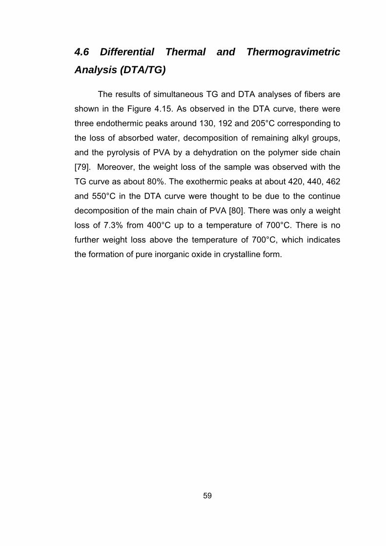
4.6 Differential Thermal and Thermogravimetric
Analysis (DTA/TG)
The results of simultaneous TG and DTA analyses of fibers are
shown in the Figure 4.15. As observed in the DTA curve, there were
three endothermic peaks around 130, 192 and 205°C corresponding to
the loss of absorbed water, decomposition of remaining alkyl groups,
and the pyrolysis of PVA by a dehydration on the polymer side chain
[79]. Moreover, the weight loss of the sample was observed with the
TG curve as about 80%. The exothermic peaks at about 420, 440, 462
and 550°C in the DTA curve were thought to be due to the continue
decomposition of the main chain of PVA [80]. There was only a weight
loss of 7.3% from 400°C up to a temperature of 700°C. There is no
further weight loss above the temperature of 700°C, which indicates
the formation of pure inorganic oxide in crystalline form.
59

Figu
re 4
.15
TG
-DTA
cur
ves
of p
recu
sor f
iber
s of
alu
min
a bo
rosi
licat
e/P
VA
fibe
rs
60

CHAPTER 5
CONCLUSIONS
1. Alumina borosilicate/PVA fibers were prepared by the sol-gel
method and electrospinning technique for the first time in this
study.
2. Alumina borosilicate nanofibers, with diameters down to
150nm, were prepared through high temperature sintering
treatment.
3. The increase in the applied electric voltage decreased fiber
diameter as also observed in the literature [42].
4. A dependence of fiber diameter to tip-to-collector distance
was also observed. An increase of the tip-to-collector
distance reduced the diameter of the fibers.
5. Increasing the viscosity of the solution decreased bead
formation in electrospinning. The high viscosity eliminated the
bead formation as also noted in literature.
6. Aluminum isopropoxide was used as aluminum source
instead of aluminum ethoxide due to it has bigger alkyl group.
61

It leads to a decrease in the reaction rate and thus to an
increase in gelation time.
7. Aluminum isopropyl alcohol, which is a polar protic solvent,
was used instead of toluene, which is non-polar aprotic
solvent. In this manner, it was observed that the gelation time
increased, and more uniform fibers were obtained.
8. The alcohol concentration in the electrospinning solution was
also important to prevent fast gelation problem. Alcohol
retards gelation.
9. The XRD spectra showed that Al6Si2O13 and Al4B2O9 crystals,
and vitreous silica formed around 800oC.
10. When the sintering temperature was increased to 1000oC
cristobalite and new Al18B4O33 crystals were observed.
62

RECOMMENDATIONS
• By making further modifications on the parameters of sol-
gel and electrospinning processes, uniform alumina
borosilicate nanofibers with smaller diameter could be
formed.
• Different metal alkoxides, which hydrolyse slowly, should
be tried in order to avoid fast gelation.
• Mechanical, electrical or chemical characterization should
be carried out for this ceramic material to explore its
potential industrial applications.
63

REFERENCES
1. Richard Feynman There’s Plenty of Room at the Bottom. An Invitation to Enter a New Field of Science, lecture, annual meeting of the American Physical Society, California Institute if Technology, www.zyvex.com/nanotech/feynman.html, July 13, 2006.
2. Drexler, K.E., “Engines of Creation”, Anchor Press, New York,
1986. 3. Ding, B., Kim, H., Lee, S., Shao, C., Lee D., Park, S., et al.,
“Preparation and Characterization of a nanoscale poly(vinyl alcohol) fiber aggregate produced by an electrospining method”, Journal of Polymer Science: Part B: Polymer Physics, 40, p1261, 2002.
4. Stephens, J., Frisk, S., Meglski, S., Rabolt, J., Chase, D., “Real
time Raman studies of electrospun fibers”, Applied Spectroscopy, 55, p1287, 2001.
5. Liu, H., Hsieh, Y., “Ultrafine fibrous cellulose membranes from
electrospinning of cellulose acetate” Journal of Polymer Science: Part B: Polymer Physics 40, p2119, 2002.
6. Shin, Y., Hohman, M., Brenner, M., Rutledge, G., “Experimental
characterization of electrospinning: the electrically forced jet and instabilities”, Polymer, 42, p9955, 2001.
7. Schreuder-Gibson, H., Gibson, P., Senecal, K., Sennett, M.,
Walker, J., Yeomans, W., et al., “Protective textile materials based on electrospun nanofibers”, Journal of Advanced Materials, 34(3), p44, 2002.
8. Fang, X., Reneker, D., “DNA fibers by electrospinning”, Journal
of Macromolecule Science Physics, B36, p169, 1997. 9. Matthews, J., Wnek, G., Simpson, D., Bowlin, G.,
“Electrospinning of Collagen Nanofibers”, Biomacromolecules, 3, p232, 2002.
64

10. Kim, J., Lee, D., “Thermal properties of electrospun polyesters” Polymer Journal, 32, p616, 2000.
11. Shao, C., Kim, H., Gong, J., Lee, D., “A novel method for making
silica nanofibres by using electrospun fibres of polyvinylalcohol/silica composite as precursor”, Nanotechnology, 13, p635, 2002.
12. Dai, H., Gong, J., Kim, H., Lee, D., “A Novel Method for
Preparing Ultra-Fine Alumina-Borate Oxide Fibres Via an Electrospinning Technique”, Nanotechnology, 13, p674, 2002.
13. Choi, S., Chu, B., Lee, S., Lee, S., Im, S., Kim, S., Park, J.,
“Titania-doped Silica fibers Prepared by Electrospinning and Sol-Gel Process”, 30, p215, 2004.
14. Viswanathamurthi, P., Bhattarai, N., Kim, H., Lee D., Kim, S.,
Morris, M., “Preparation and Morphology of Niobium Oxide Fibres by Electrospinning”, Chem. Phys. Lett., 374, p79, 2003.
15. Viswanathamurthi, P., Bhattarai, N., Kim, H., Khil, M., Lee, D.,
Suh, E., “GeO2 Fibers: Preparation, Morphology and Photoluminescence Property”, J. Chem. Phys., 121, p441, 2004.
16. Kim, H., Viswanathamurthi, P., Bhattarai, Lee, D., “Preparation
and Morphology of Vanadium Oxide Fibers” Chem. Phys. Lett., 5, p224, 2003.
17. Yang, X., Shao, C., Liu, Y., Mu R., Guan, H., “Nanofibers of
CeO2 via an Electrospinning Technique”, Thin Solid Films, 478, p228, 2005.
18. Yu, N., Shao, C., Liu, Y., Guan, H., Yang X., “Nanofibers of
LiMn2O4 by electrospining”, J. Colloid Interface Sci., 285, p163, 2005.
19. Wang, Y., Santiago-Aviles, J., “Synthesis of Lead Zirconate
Titanate Nanofibres and the Fourier-Transform Infrared Characterization of their Metallo-Organic Decomposition Process”, Nanotechnology, 15, p32, 2004.
65

20. Park, H., “Fabrication of lanthanum copper oxide nanofibers by electrospinning,” Ph.D. Thesis, University of Florida, 2005.
21. Wu, Y., Hench, L., Du, J., Choy, K., Guo, J., ‘‘Preparation of
Hydroxyapatite Fibers by Electrospinning Technique,’’ J. Am. Ceram. Soc., 87, p988, 2004.
22. Madhugiri, S., Sun, B., Smirniotis, P., Ferraris, J., Balkus, K.,
“Electrospun Mesoporous Titanium Dioxide Fibers”, Micropor.Mesopor.Mater.,69, p77, 2004.
23. Dharmaraj, N., Park, H., Lee, B., Viswanathamurthi, P., Kim,
H., Lee, D. “Preparation and Morphology of Magnesium Titanate Nanofibres Via Electrospinning”, Inorg. Chem. Commun., 7, p431, 2004.
24. Dharmaraj, N., Park, H., Kim C., Kim H., Lee D., “Nickel
Titanate Nanofibers by Electrospinning”, Mater. Chem. Phys., 87, p5, 2004.
25. Wang, Y., Aponte, M., Leon, N., Ramos, I., Furlan, R., Evoy,
S., Santiago-Aviles, J., “Synthesis and Characterization of Tin Oxide Microfibres Electrospun from a Simple Precursor Solution”, Semicond. Sci. Technol., 19, p1057, 2004.
26. Yuh, J.,Nino, J., Sigmund, W., “Synthesis of Barium Titanate (BaTiO3) Nanofibers via Electrospinning”, Mater. Lett., 59, p3645, 2005.
27. Guan, H., Shao C., Wen S., Chen, B., Gong, J., Yang, X., “A
Novel Method for Preparing Co3O4 Nanofibers by Using Electrospun PVA/Cobalt Acetate Composite Fibers as Precursor”, Mater. Chem. Phys., 82, p1002, 2003.
28. Shao C., Yang, X., Guan, H., Liu, Y., Gong, H., “Electrospun
Nanofibers of NiO/ZnO Composite”, Inorg. Chem. Commun., 7, p625, 2004.
29. Shao C., Yang, X., Guan, H., Liu, Y., Gong, H., Yu, N.,Yang,
X., “A Novel Method for Making ZrO2 Nanofibres Via an Electrospinning Technique”, J. Cryst. Growth, 267, p380, 2004.
66

30. Li, D., Herricks, T., Xia, Y., “Magnetic Nanofibers of Nickel Ferrite Prepared by Electrospinning”, Appl. Phys. Lett., 83, p4586, 2003.
31. Wang, A., Singh, H., Hatton, T., Rutledge, G., “Field-
Responsive Superparamagnetic Composite Nanofibers by Electrospinning”, Polymer, 45, p5505, 2004.
32. Shao, C., Guan, H., Liu, Y., Li, X., Yang, X., Preparation of
Mn2O3 and Mn3O4 Nanofibers via an Electrospinning Technique”, J. Solid State Chem., 177, p2628, 2004.
33. Rayleigh, L., Phil. Mag. 14, p184, 1882. 34. Zeleny, J., Phys. Rev. 10, p1, 1917. 35. Vonnegut, B., Neubauer, R., “Production of monodisperse
liquid particles by electrical atomization”, Journal of Colloid Science, 7, p616, 1952.
36. Taylor, G., “Electrically driven jets”, Proceedings of the Royal
Society of London, 313, p453, 1969. 37. Hendricks, C., Hogan, J., Schneider, AIAA Journal, 2, p955,
1964. 38. Michelson, D., “Electrostatic atomization”, Adam Hilger,
Bristol, 1990. 39. Hayati, I., Bailey, A., Tadros F., “Mechanism of stable jet
formation in electrohydrodynamic atomization” Nature 319, p41, 1986.
40. Formhals, A., “Process and Apparatus for Preparing Artificial
Threads”, US Patent 1975504, 1934. 41. Baumgarten, P., “Electrostatic spinning of Acrylic microfibers”,
J. Colloid Interface Sci., 36, p71, 1971. 42. Larrondo, L., Manley, R., “Electrostatic fibre spinning from
polymer melts: Experimental observations on fibre formation and properties” J. Polymer Sci.: Polymer Phys., 19, p909, 1981.
67

43. Larrondo, L., Manley, R., “Electrostatic fibre spinning from
polymer melts: Examination of the flow field in an electrically driven jet” J. Polymer Sci.: Polymer Phys., 19, p921, 1981.
44. Larrondo, L., Manley, R., “Electrostatic fibre spinning from
polymer melts: Electrostatic deformation of a pendant drop of polymer melt” J. Polymer Sci.: Polymer Phys., 19, p933, 1981.
45. Doshi, J., Reneker D., “Electrospinning process and
applications of electrospun fibers”, J. Electrostat. 35, p151, 1995.
46. Fong, H. I.C., Reneker D. H., “Beaded nanofibers formed
during electrospinning”, Polymer, 40, p4585, 1999.
47. Reneker D., Yarin, A., Fong, H., Koombhongse, S., “Bending instability of electrically charged liquid jets of polymer solutions in electrospinning”, Journal of Applied Physics, 87, p4531, 2000.
48. Fong, H., Reneker, D., “Electrospinning and the formation of
nanofibers” Hanser Gardner Publications, NY, 2001. 49. Yarin, A. L., Koombhongse, S., Reneker, D., “Bending
instability in electrospinning of nanofibers”, Journal of Applied Physics 89, p3018, 2001.
50. Doshi, J.,Reneker, D., “Electrospinning process and
application of electrospun fibers”, Journal of Electrostatics 35, p151, 1995.
51. Hohman, M., Shin, M., Rutledge, G., Brenner, M.,
“Electrospinning and electrically forced jets. I. Stability theory”, Physics of Fluids, 13, p2201, 2001.
52. Hohman, M., Shin, M., Rutledge, G., Brenner, M.,
“Electrospinning and electrically forced jets: II. Applications” Physics of Fluids 13, p2221, 2001.
68

53. Shin, M., Hohman, M., Brenner, M., Rutledge, G., “Electrospinning: A whipping fluid jet generates submicron polymer fibers”, Appl. Phys. Lett. 78, p1149, 2001.
54. Deitzel, J., Kleinmeyer, J., Harris, D., Tan, N., “The effect of
processing variables on the morphology of electrospun nanofibers and textiles” Polymer 42, p261, 2001.
55. Koombhongse, S., Reneker, D., “Branched and split fiber from
electrospinning process”, Book of Abstracts. In: New Frontiers in Fiber Science, Spring Meeting, www.tx.ncsu.edu/jtatm/volume1specialissue/posters/posters_part1.pdf, February 2, 2006.
56. Pierre, A., “Introduction to sol-gel processing”, Kluwer
Academic Publishers, 4, 1998. 57. Brinker, C., Scherer, W., “Sol-Gel Processing”, Pergamon
Press, London, 1990. 58. Wright, J., Sommerdijk, N., “Sol-Gel Materials Chemistry and
Applications”, Taylor & Francis, London, 2001.
59. Haertling, G., Land, C., Ferroelectrics 3, 269, 1979. 60. Yoldas, B., "Monolithic Glass Formation by Chemical
Polymerization", J. Mat. Sci. 14, p1843, 1979. 61. Mouchon, E., Colomban, P., “Oxide ceramic matrix-oxide fibers
woven fabric composites exhibiting dissipative fracture behavior”, Composites 26, p175, 1995.
62. Zhu, D., Jilavi, M., Kriven, W., “Synthesis and characterization
of mullite and YAG fibers grown from deeply undercooled melts”, Ceram. Eng. Sci. Proc. 18, p31, 1997.
63. Chen, Y., Li, J., Dai J., 2001 “Si and SiOx nanostructures
formed via thermal evaporation”, Chemical Physics Letters, 344, p450, 2001.
64. Liu, Z., Zhou, W., Sun, L., Tang, D., Zou, X., Li, Y., Wang, Y.,
Xie, S., “Growth of amorphous silicon nanowires”, Chemical Physics Letters, 341 p523, 2001.
69

65. Zhu, Y., Hu, W., Hsu, W., “A simple route to silicon-based
nanostructures”, Adv. Mater. 11, p844, 1999. 66. Readey, M., “Formation and Sintering Characterization of
Aluminum Borate Whiskers”, J. Am. Ceram. Soc. 75, p3452, 1992.
67. Liu, Y., Ren, W., Zhang, L., Yao, X., “New method for making
porous SiO2 thin films”, Thin Solid Films, 353, p124, 1999. 68. Kern, W, et al., Z. Phys. 108, 295, 1938. 69. Nakane, K., Yamashita, T., Iwakura, K., Suzuki, F., “Properties
and Structure of Poly(vinyl alcohol)/Silica Composites”, J. Appl. Polym. Sci. 74 p133, 1999.
70. Kern, W., “Infrared Spectroscopic Method for Compositional
Determination of Vapor-Deposited Borosilicate Glass Films and Results of its Application”, RCA Review, 32, p429, 1993.
71. Matossi, F., Z. Phys. 108, p295, 1938. 72. Poh, N., Nur, H., Muhid M., Hamdan, H., “Sulfated AlMCM-41:
Mesoporous Solid Bronsted Acid Catalysts for Dibenzoylation of Biphenyl”, Catalysis Today, 114, p257, 2006.
73. Andrianov, K., Bradley, D., “Metalorganic polymers” Polymer
Reviews, New York, Interscience, vol 8, 1965. 74. Sopicka-Lizer, M., “Thermal Decomposition Of Aluminum
Hydroxychloride” Euroceramic, Elsevier Appl. Sc, New York, vol 1, p1609, 1989.
75. Nishio, Y., Manley, R., “Cellulose-poly(vinyl alcohol) blends
prepared from solutions in N,N-dimethylacetamide-lithium chloride”, Macromolecules, 21 p1270, 1988.
76. Hamzawy, E., Ali, A., “Sol-gel synthesis and crystallization of
aluminum borosilicate”, Ceramics International, 27, p607, 2001.
70

77. Rainho, J., Rocha, J., Carlos, L., Almeida, R., “29Si Nuclear-Magnetic-Resonance and Vibrational Spectroscopy Studies of SiO2-TiO2 Powders Prepared by the Sol-Gel Process” J. Mater. Res. 16, p2369, 2001.
78. Xu, J., Thompson, S., O’Keefe, E., Perry, C., “Iron oxide-silica
nanocomposites via sol-gel processing”, Materials Letters 58, p1696, 2004.
79. Koji, N., Tomonori, Y., Kenji, I., Fumio, S., J. Appl. Polym. Sci.
74, p133, 1999. 80. Chikako, N., Takeo, S., Toshio, Y., Masataka, S., “The effects
of chromium compounds on PVA-coated AN and GAP binder pyrolysis, and PVA-coated AN/GAP propellant combustion”, Fuel, 77, p321, 1998.
71