Project 2016-02 CIP Modifications next 3 slides addresses concepts related to Questions 8 and 9 on the comment form. The SDT is seeking comments on the mana\൧ement plane logical
47
Project 2016-02 CIP Modifications Webinar on Standard Drafting Team Considerations for the Use of Virtualization in the CIP Environment March 21, 2017
Project 2016-02CIP ModificationsWebinar on Standard Drafting Team Considerations for the Use of Virtualization in the CIP EnvironmentMarch 21, 2017
Presenter
Presentation Notes
Good morning to all and thank you for joining us for this webinar on virtualization
RELIABILITY | ACCOUNTABILITY2
• Administrative Items Antitrust and Disclaimers Webinar Format
• Standard Drafting Team
• Opening Remarks and Introduction of Presenters
• Logical Isolation
• Centralized Management System (CMS)
• Resiliency and Virtual Machines
• Questions and Answers
Agenda
Presenter
Presentation Notes
RELIABILITY | ACCOUNTABILITY3
• NERC Antitrust Guidelines It is NERC’s policy and practice to obey the antitrust laws and to avoid all
conduct that unreasonably restrains competition. This policy requires the avoidance of any conduct that violates, or that might appear to violate, the antitrust laws. Among other things, the antitrust laws forbid any agreement between or among competitors regarding prices, availability of service, product design, terms of sale, division of markets, allocation of customers or any other activity that unreasonably restrains competition.
• Notice of Open Meeting Participants are reminded that this webinar is public. Notice of the webinar
was posted on the NERC website and the access number was widely distributed. Speakers on the call should keep in mind that the listening audience may include members of the press and representatives of various governmental authorities, in addition to the expected participation by industry stakeholders.
Administrative Items
RELIABILITY | ACCOUNTABILITY4
CIP Standard Drafting Team
RELIABILITY | ACCOUNTABILITY5
Drafting Team Scope
Issue Area Source Status
LERC definition Order 822 Completed
Transient devices for low impact Order 822 Completed
Communication between BES Control Centers Order 822 Development in progress
Cyber Asset and BES Cyber Asset Definitions V5TAG Development in progress
Network and Externally Accessible Devices V5TAG Development in progress
Transmission Owner (TO) Control Centers V5TAG Posted for informal comment
Virtualization V5TAG Posted for informal comment
CIP Exceptional Circumstances SAR Development in progress
“Shared BES Cyber Systems” in CIP-002-5.1a EnergySec RFI Completed
RELIABILITY | ACCOUNTABILITY6
• Christine Hasha – Electric Reliability Council of Texas (ERCOT) • Philippe Labrosse – Hydro-Québec TransÉnergie• Forrest Krigbaum – Bonneville Power Administration• Matthew Hyatt – Tennessee Valley Authority (TVA)• Larry Good – ACT-1 Group
Presenters
Presenter
Presentation Notes
Christine Hasha from ERCOT, Philippe Labrosse from Hydro-Québec TransÉnergie Forrest Krigbaum from Bonneville Power Administration Matthew Hyatt from TVA, Larry Good from ACT-1 Group
RELIABILITY | ACCOUNTABILITY7
Presenter
Presentation Notes
The objective of this portion of the presentation is to provide background on the SDT’s process of examining CIP requirements in the context of new virtualization technologies and methods. The intent is to encourage detailed comments from Industry on the recently published unofficial comment form. The virtualization sub-team of the SDT has been working on bringing clarity on different subjects of virtualization for the last few months. As you may be aware virtualization brings in scope a number of different topics ranging from change management, information protection, categorization, VLANs, just to name a few. This first comment form is seeking comments on some of those subjects. For those who have read the comment form, you have seen that we are seeking comments on the Systems approach to demonstrating compliance versus the Cyber Asset approach, the definition of Cyber Asset so that it now specifically makes a reference to Cyber Assets that are virtual, logical isolation and VLANS as well as Centralized Management Systems. Today’s webinar will hopefully provide you with an introduction to two of the more technical subjects, namely logical isolation and Centralized Management Systems. Although we might get technical at times, we tried to use industry recognized terms to appeal to a broader audience
RELIABILITY | ACCOUNTABILITY8
Data / Management Plane Isolation
Presenter
Presentation Notes
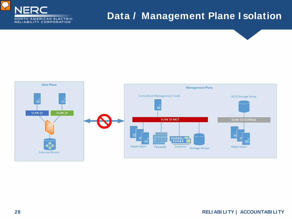
Access to the control surface of a cyber system is known as the management plane. This is where the Cyber Asset is configured and managed by a limited group of administrators as opposed to the data plane, where users may access the service or business function offered by the Cyber Asset. While both of these functions CAN co-exist in one data stream, best practice is to separate them to reduce risk to the Cyber System where possible. Isolation of the Management Plane can also help protect the Control Plane (which is the logic embedded in the code of the Cyber Asset) from malware and cyber threat actors. Here we see a drawing that represents the logical topology for this presentation. As you can see; Logical isolation exists between the in-band production networks on the left and the out of band management plane which consists of centralized management tools, hypervisors, firewalls, switches, storage arrays, and storage networks. We will refer back to this drawing throughout the presentation as it details the intent of our example virtual architecture. The double arrow with a no sign represents logical isolation. We’ll use this symbol throughout the presentation to represent logical isolation between devices or groups of devices.
RELIABILITY | ACCOUNTABILITY9
Basic Virtualization Platform
Presenter
Presentation Notes
This slide lays out the foundation of an example virtual architecture. The grey boxes represent physical infrastructure on top of which we’re going to lay our logical, virtual infrastructure. This slide shows 3 physical servers and one physical switch. On the top we have 3 hypervisors with virtual switches that are connected to a layer 2 switch below. It is important to note that the links between the hypervisors and the layer 2 switch are trunks in this example. To keep consistency we will use this drawing to build our example virtual architecture.
RELIABILITY | ACCOUNTABILITY10
Add Centralized Management
Presenter
Presentation Notes
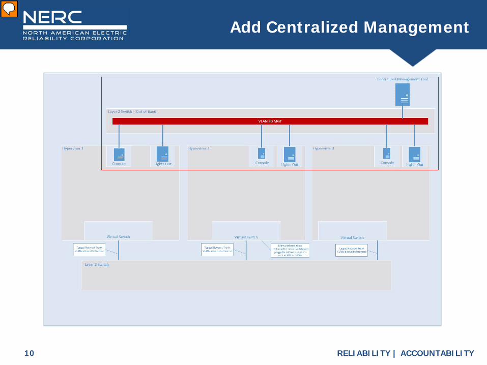
The next 3 slides addresses concepts related to Questions 8 and 9 on the comment form. The SDT is seeking comments on the management plane logical isolation from the data plane. Most virtualization platforms require the use of a management plane to perform advanced functions such as the creation of virtual machines, virtual networks, shared storage, etc. Here we are adding a centralized management tool that has out of band access to both the lights out interfaces of our physical machines as well as the console port of our hypervisors. This will give the centralized management tool visibility of our virtualized infrastructure.
RELIABILITY | ACCOUNTABILITY11
Add Virtual Local Area Networks (VLANs)
Presenter
Presentation Notes
Now we need to build the bones of our virtual topology. To do that we need to create some production networks. As you can see we have added VLAN10 and VLAN20 to both the physical layer 2 switch and virtual switches on each hypervisor. These VLANs are allowed to traverse the trunks between the virtual switch and the physical switch and remain logically isolated.
RELIABILITY | ACCOUNTABILITY12
Add Virtual Machines (VMs)
Presenter
Presentation Notes
Now we can use our management plane to add VMs to our architecture on hypervisor 2. These will serve as production services or workloads for the sake of this presentation. In examining virtualization, the SDT considered centralized management systems or consoles for these environments. These systems allow for the mass addition, deletion and modification of virtual machines and networks. Access to the control surface of a cyber system is known as the management plane. The management plane is where the virtual infrastructure is configured and managed by a limited group of administrators as opposed to the data plane. The data plane is where the end user’s access to the virtual machine’s business function takes place. To meet the security objective of protecting a BES Cyber System from threats in the data plane, the management plane should be isolated from the data plane. These types of controls are referred to as out of band management. On the comment form, the SDT is considering limiting the scope of management plane protection requirements to high and medium impact Control Centers because these environments contain the highest risk. Question 8 is asking if you agree with the SDT’s approach to require the isolation between the data plane and the management plane. Question 9 is asking if you agree with limiting the applicability to high and medium impact Control Centers. Please provide your rationale when answering questions in the comment form.
RELIABILITY | ACCOUNTABILITY13
• The proposed Centralized Management System (CMS) definition is: A centralized system for administration or configuration of BES Cyber
Systems, including but not limited to systems management, network management, storage management, or patch management.
Centralized Management System (CMS)
Presenter
Presentation Notes
On the comment form, the SDT is considering adding a defining to Centralized Management Systems: “A centralized system for administration or configuration of BES Cyber Systems, including but not limited to systems management, network management, storage management, or patch management” Question 6 is asking if you agree with the proposed definition of CMS. Question 7 is asking if you agree with the SDT’s approach to reference the CMS specifically as a type of applicable system in the CIP standards Please provide your rationale when answering questions in the comment form.
RELIABILITY | ACCOUNTABILITY14
VMs cannot see Tagged Traffic (Q5)
Presenter
Presentation Notes
This particular slides addresses Question 5 on the comment form. The SDT is seeking comments on logical isolation using VLANs and whether or not the CIP-005 currently addresses it. Here we have an expanded view of our example architecture that allows us to see the Virtual Machines more closely. It is important to point out that the virtual machine is connected using an untagged logical ethernet interface to the virtual switch and can not see traffic from the upstream trunk to the physical switch. This prevents this virtual machine from being able to observe traffic from or inject traffic to other virtual machines. This is a key part of how logical isolation is created and is a baseline function of a hypervisor. On the comment form, the SDT asserts that VLANs providing logical isolation are not addressed explicitly in CIP-005-5, and controls may be necessary to isolate BES Cyber Systems. Modifications to requirements, controls or clarifications in the Guidelines and Technical Basis might be needed. Question 5 is asking if the current requirements of CIP-005-5 are sufficient to address logical isolation using VLANs. Please provide your rationale when answering the question in the comment form.
RELIABILITY | ACCOUNTABILITY15
VMs are Mobile
Presenter
Presentation Notes
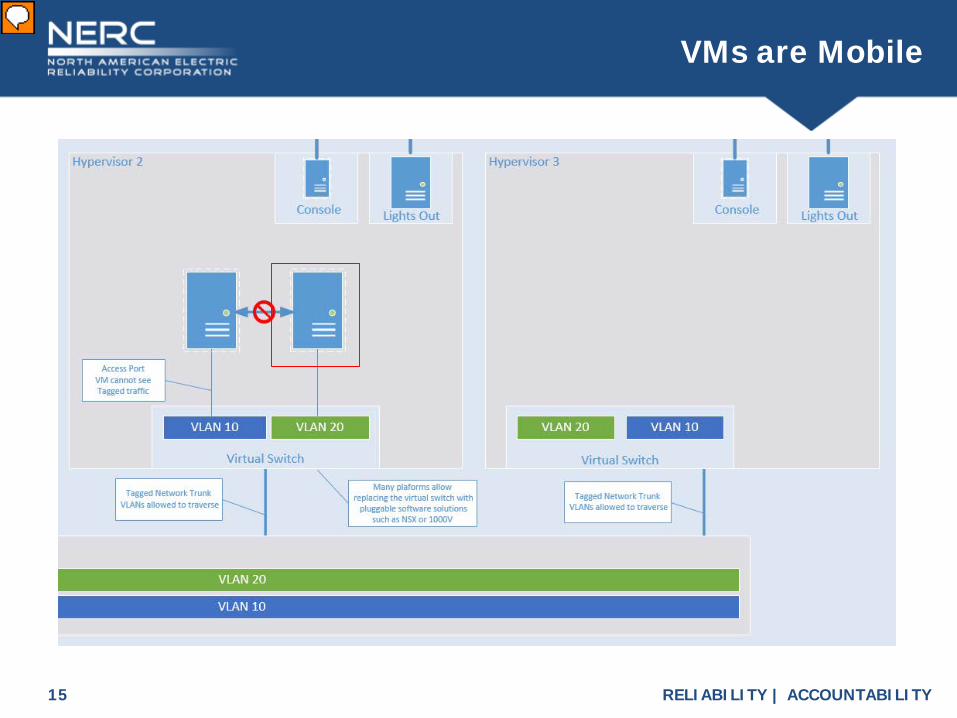
As we zoom out, you can now see hypervisor 3. Since both VLAN 10 and 20 are trunked to the physical Layer 2 switch and all hypervisors, this provides for guest mobility across hypervisors.
RELIABILITY | ACCOUNTABILITY16
VMs are Mobile
Presenter
Presentation Notes
The virtual machine can now be migrated to other hypervisors while maintaining its logical isolation. This allows the underlying hardware to be abstracted from the production service which improves the services recovery time objective or RTO.
RELIABILITY | ACCOUNTABILITY17
Introspection: Malware Detection
Presenter
Presentation Notes
Now, lets add another production service to VLAN10 on Hypervisor 1. Since the hypervisor has such a unique posture in its relationship to our production services we can begin to implement some very important security features.
RELIABILITY | ACCOUNTABILITY18
Introspection: Malware Detection
Presenter
Presentation Notes
As you can see we have added a platform for pluggable privileged introspection software packages. These intend to replace your agent-based malware detection software that is installed inside the operating system of the VM. By isolating the code base and moving the malware detection outside of the operating system it can no longer be tampered with by the malware that might make its way onto the GuestVM. Conventionally malware could detect and disable the malware detection mechanism. We have included references on a later slide for further reading.
RELIABILITY | ACCOUNTABILITY19
Policy Based Firewalling
Presenter
Presentation Notes
From the same privileged position we use for introspection we can now also do some more advanced firewall services for our workloads. As you can see we have added a policy based firewall placed between the virtual machine and its virtual switch. Conventional firewalls are restricted to IP and Port as a means of writing Access Control Lists but now with the visibility afforded by the virtual architecture we are able to apply much more secure controls. We can now base controls on user accounts, service accounts, specific processes, as well as IP and Port. This virtual firewall is also portable and can migrate through the infrastructure along side its workload which solves some very complex firewall issues. This reduction in complexity increases the resiliency and reliability of the system.
RELIABILITY | ACCOUNTABILITY20
Topology Overview
Presenter
Presentation Notes
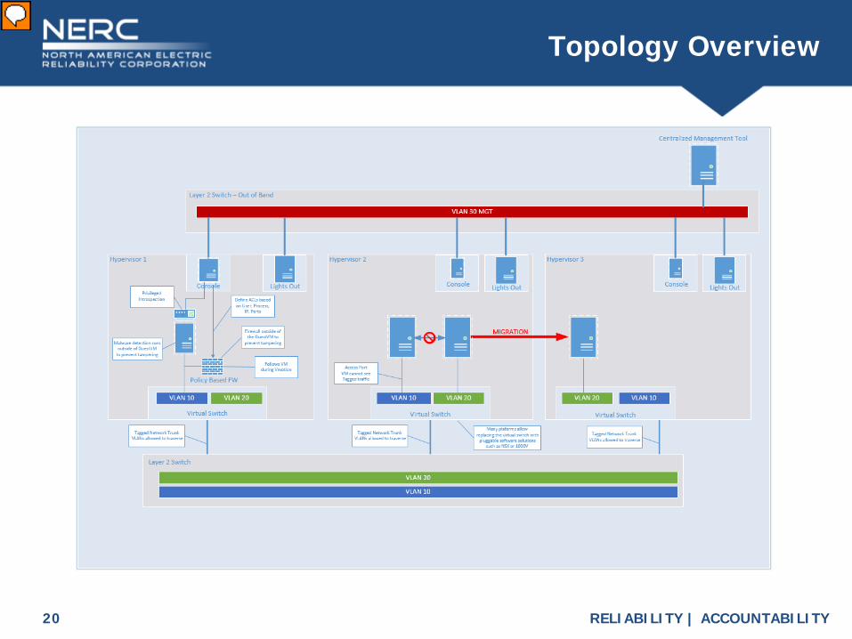
Here you see a zoomed out view of the architecture we have built. We have talked about logical isolation but we have not talked about how you build communications between VLAN10, VLAN20, and the rest of the network.
RELIABILITY | ACCOUNTABILITY21
Add a Physical Firewall
Presenter
Presentation Notes
As you can see we have added an example of a physical firewall to our example architecture.
RELIABILITY | ACCOUNTABILITY22
Add a Physical Firewall
Presenter
Presentation Notes
Here we can see that our physical firewall is connected to the physical layer 2 switch using a trunk similar to the hypervisor and a second physical interface to an upstream router. The trunk allows the firewall to see both of the VLANs in the layer 2 switch and serve as a layer 3 boundary between them.
RELIABILITY | ACCOUNTABILITY23
Topology Overview
Presenter
Presentation Notes
Let’s zoom back out and remove the physical firewall. Now what if we wanted to do the same thing with a virtual firewall?
RELIABILITY | ACCOUNTABILITY24
Adding a Virtual Firewall
Presenter
Presentation Notes
Here we have added a virtual firewall that runs as a virtual machine with a separate physical interface to an upstream router.
RELIABILITY | ACCOUNTABILITY25
Adding a Virtual Firewall
Presenter
Presentation Notes
This is a zoomed in view of the firewall’s virtual machine which allows us to see that it is connected logically to VLAN10, VLAN20, and uses a new VLAN50 on a separate virtual switch to the upstream router. Using a virtual firewall allows for additional flexibility but works the same way as its physical counterpart.
RELIABILITY | ACCOUNTABILITY26
Topology Overview
Presenter
Presentation Notes
Let’s zoom back out and take one last look at our virtual topology map. We will just briefly touch on how the storage network is layered onto the same physical infrastructure.
RELIABILITY | ACCOUNTABILITY27
Storage Topology Overview
Presenter
Presentation Notes
Shared storage is a prerequisite to most of the mobility features in a virtualized infrastructure. In this model we are using an ISCSi storage array to build shared storage solution. This requires at least one additional VLAN for the hypervisors to get access to the storage array. VLAN70 traverses the same physical topology but is logically isolated.
RELIABILITY | ACCOUNTABILITY28
Data / Management Plane Isolation
Presenter
Presentation Notes
Now let’s look back at our logical diagram again to tie this all together. The production networks vlan10 and vlan20 on the left are what we built with both our physical firewall and virtual firewall solutions. In the middle you see our out-of-band management VLAN with its visibility into the architecture; and on the right you see our storage network that allows shared storage to work all maintaining logical isolation.
RELIABILITY | ACCOUNTABILITY29
Physical Isolation and Electronic Security Perimeter (ESP)
Presenter
Presentation Notes
How does this apply to CIP? Now let’s apply an ESP boundary to our example architecture. Take note of the logical topology at the top of the diagram.
RELIABILITY | ACCOUNTABILITY30
Q4: Logical Isolation and ESP
Presenter
Presentation Notes
This particular slides addresses Question 4 on the comment form. The SDT is seeking comments on this type of configuration and whether or not the CIP-005 currently addresses it. In virtualized environments, the physical infrastructure is capable of being shared between BES Cyber Systems and other non-CIP Cyber Assets while maintaining isolated virtualized environments for each. On this slide you can see how an ESP could be drawn using logical isolation. On hypervisor 2, you can see that there are 2 virtual machines that are inside the ESP and one that is not. You can also see that the ESP extends through the physical layer 2 switch as well as to hypervisor 1. Now take a look at the logical topology at the top of the slide and notice how it is identical to the previous slide using physical isolation.
RELIABILITY | ACCOUNTABILITY31
Presenter
Presentation Notes
This concludes the section on Isolation and the management plane.
RELIABILITY | ACCOUNTABILITY32
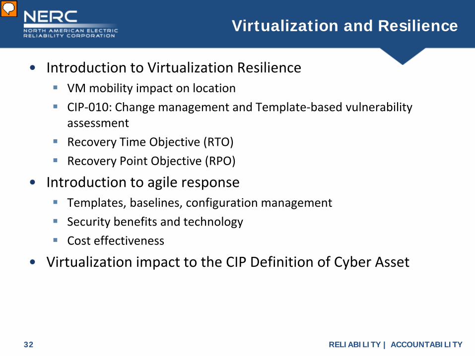
• Introduction to Virtualization Resilience VM mobility impact on location CIP-010: Change management and Template-based vulnerability
assessment Recovery Time Objective (RTO) Recovery Point Objective (RPO)
• Introduction to agile response Templates, baselines, configuration management Security benefits and technology Cost effectiveness
• Virtualization impact to the CIP Definition of Cyber Asset
Virtualization and Resilience
Presenter
Presentation Notes
We have covered a lot of information so far to try and level set on logical separation of Data Plane and Management Plane, introduced in-band and out-of-band, described the absolute necessity of Layer 2 switches in underlay and overlay to achieve virtualization and described the need to address the security at all layers and plains. We have described the need and definition for Centralized Management Consoles. We have provided a proposed definition. We have explained the issue with the mobility of VMs and how it relates to cyber asset device snapshots. Some of the security features such as introspection, logical isolation, and Storage Topology Overviews have been discussed. We have contrasted the concepts of Logical isolation and ESPs. Now we will introduce some additional topics of Resiliency, Mobility, Agile Response, Security Features and Cost. The intent of this portion of the presentation is to address the benefits of virtualization to reliability, while acknowledging and discussing difficulties in applying the current standards. Again, the hope is to encourage detailed feedback in the unofficial comment form by providing some background to the questions and how the SDT came to this point. We will end by tying this all back to the question on definition of Cyber Asset and finish out by addressing the CIP Systems approach from Question 1 of the comment form. The slide deck will be available for your download with a list of our resources and have some time left over for questions we have received.
RELIABILITY | ACCOUNTABILITY33
VM Resilience:Dynamic Resources and Mobility
Presenter
Presentation Notes
You may recognize this diagram from Slide 8. The virtual environment’s distinguishing feature is abstraction of the workload from the hardware, allowing for VM mobility. A common criticism of virtualization is the possibility of resource starvation. Resources such as memory and CPU are pooled and made available to multiple Guests. However, configuration of physical resources available to a guest does not have to be static. Dynamic allocation allows prioritization and minimum reservations of physical resources, giving a greater overall resource availability where and when it is needed. Guest VM mobility is another core benefit of virtualization, and can even be a mitigating factor for the possibility of resource starvation. In addition to dynamic resource allocation within the host, VM mobility can be configured and even automated in response to outage, congestion or resource constraints, and cyber attack. When aggregate workload needs exceed the communal resources available on a given host, migration of the guest to a different host with greater resources available is trivial in comparison to building another instance of the specifically-configured guest VM.
RELIABILITY | ACCOUNTABILITY34
VM Mobility and Asset Location (CIP 5)
Presenter
Presentation Notes
Although there is concern about describing the location of a virtual cyber asset due to its mobile nature, we can still provide evidence of the asset being contained within the ESP. A standard configuration parameter for virtual machines is “affinity”, or the allowable targets that a VM may migrate to. Many other attributes of a VM may be specified, including boot order, pairing of Security Virtual Appliances with the VMs (workloads) they are intended to protect, and others. The last two slides show the challenge of drafting requirements language to address ESPs in a Virtual Environment Question 4 in the comment form addresses sharing resources between CIP and non-CIP cyber assets. When responding to Question 4 your detailed rationale will help the SDT in drafting appropriate language.
RELIABILITY | ACCOUNTABILITY35
VM Resilience: Recovery Time Objective (RTO)
Presenter
Presentation Notes
Despite the best planning, hardware occasionally fails. Two dimensions of disaster recovery are Recovery Time Objective and Recovery Point Objective. Proper design of the physical hypervisor infrastructure provides for highly-available hardware redundancy. Abstracting the workload from the hardware allows for fast recovery if one physical host does have an outage. The recovery of a VM moving to a new host is typically much faster than a physical machine’s boot process (ranging from practically undetectable, to seconds, opposed to minutes for physical servers.) Rebuilding a catastrophic failure of a physical host to operational status can take hours/days/weeks.
RELIABILITY | ACCOUNTABILITY36
Traditional Environment:• Backup files and directories (lengthy process)• Test restoration periodically
Lengthy process, often skipped, media failures Requires a fresh build
• Outage scenario Requires a fresh build from scratch, including exact settings and
software Restore files and directories from backup media Validate backup integrity and completeness (often inadequate) Delete / recreate computer objects in directory services
VM Resilience: Recovery Point Objective (RPO)
Presenter
Presentation Notes
Traditional backup and recovery solutions make copies of files and directories on a server. In the event of an unrecoverable physical machine, a new machine must be built, configured, and the files/directories restored to it. In specific circumstances, additional work is required to eliminate and re-configure attributes specific to the host ID of the original, such as machine or agent GUIDs. The process of rebuilding from a traditional backup is lengthy and rife with opportunity for human error; e.g., poor planning or poor selection of files requiring backup, in addition to the common problem of corrupted or missing files and directories.
RELIABILITY | ACCOUNTABILITY37
Virtual Environment:• Configure Snapshot interval • Test restoration
Periodically boot Snapshot image to isolated test network, takes minutes to verify state and operation
• Outage scenario Locate desired Snapshot and boot to target host
o Snapshot is literally just an earlier state of the actual Cyber Asset to be restored
o No deletion / recreation of computer objects in directory service, o no change to IP address, hostname, GUID etc.
VM Resilience: RPO
Presenter
Presentation Notes
The underlying mechanism of creating and storing VMs provide benefits not only in terms of Recovery Time Objective, but also of Recovery Point Objective (RPO) which is more about the completeness of the recovery. A VM is basically a file containing a complete image of a machine. Files can be easily maintained in versions. In the virtual environment, these are known as Snapshots, and they consists of a complete, bootable machine frozen at a specific point in time with all files and configurations intact. In contrast to the previous slide, a Snapshot can be booted and in most cases is completely operable immediately. Although data contained in the Snapshot may be out of date, this is also the case with physical backups. In terms of complete operating system and software configuration the advantage clearly goes to the VM.
RELIABILITY | ACCOUNTABILITY38
CIP-010: Lifecycle of a VM Baseline
Presenter
Presentation Notes
VMs can be built from vendor installation media, but this is rarely done. Maintaining updates and third party software is far easier when building from a VM template than traditional installation from media. CIP-010’s baseline configuration requirements are easy to maintain for servers when new instances are rolled out from a pre-existing image or template.
RELIABILITY | ACCOUNTABILITY39
• Develop a CIP-010 system configuration baseline and scan it• Create a VM template from the system configuration baseline• Subsequent instances created from the template inherit the
scan of the baseline (CIP-010-2, R3.3)• Per CIP-010-2, R1.3, changes to the baseline start the process
over again• The process is consistent and efficient
Agile Response
Presenter
Presentation Notes
Baseline templates may be created for generic or specific server classes and instances. For example, a baseline template could be created and stored for database servers, and another for web servers. A baseline template that contains no specific application settings but is up to date with security patches could be kept for rapid spin-up of a generic operating system when needed. Commissioning a new server from an image template takes minutes, opposed to the hours of installation, patching, and configuring necessary when installing from vendor media. This is comparable to the time advantage achieved from using imaging software such as Symantec Ghost and Microsoft Sysprep to create new physical servers, but the consistency and time regained is another order of magnitude in the virtual environment.
RELIABILITY | ACCOUNTABILITY40
Cost Effectiveness
Presenter
Presentation Notes
This slide depicts traditional parallel deployment vs shared infrastructure.
RELIABILITY | ACCOUNTABILITY41
Cost Effectiveness
Presenter
Presentation Notes
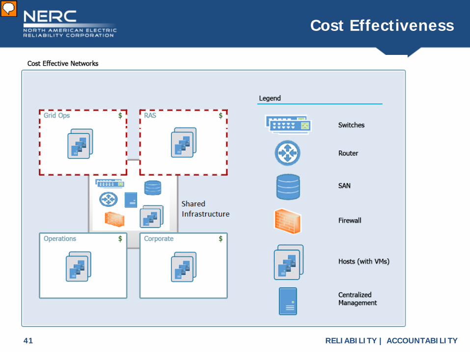
This graphic is an alternative to the previous parallel build. Here, multiple environments share certain portions of the physical infrastructure, and logically isolate the functions of the various security zones or ESPs from each other.
RELIABILITY | ACCOUNTABILITY42
• NERC has transitioned to include risk analysis in all aspects of its regulatory model, focusing the Electric Reliability Organization’s and stakeholder resources on the highest risks to the reliability of the Bulk Electric System.
• Registered entities vary in their operations and vulnerabilities; therefore, the costs for Reliability Standard implementation may vary by orders of magnitude by entity.
• Costs from the implementation of NERC Reliability Standards are implicitly considered throughout the standards development process where detailed comments are sought from the standards ballot pool, which represents a cross-section of interested participants. The Standard Drafting Team may then modify the proposed standards to provide appropriate latitude for implementation of the standards.
Security Benefits andCost Effectiveness
Presenter
Presentation Notes
Enterprise-class equipment often has enhanced security feature sets that are unavailable in less capable models. Enterprise-class equipment is often very expensive, therefore it may be economically prudent to use shared infrastructure across CIP and Non-CIP environments rather than building in parallel. This is generally understood in relation to storage area networks, but the same rationale applies to enterprise-class hypervisors and hypervisor cluster management. NERC has transitioned to include risk analysis in all aspects of its regulatory model, focusing the Electric Reliability Organization’s (ERO) and stakeholder resources on the highest risks to the reliability of the Bulk Electric System (BES). Registered entities vary in their operations and vulnerabilities; therefore, the costs for Reliability Standard implementation may vary by orders of magnitude by entity. Costs from the implementation of NERC Reliability Standards are implicitly considered throughout the standards development process where detailed comments are sought from the standards ballot pool, which represents a cross-section of interested participants. The Standards Drafting team may then modify the proposed standards to provide appropriate latitude for implementation of the standards. Please see the Resources slide at the end of the deck for further information. Cost effectiveness is often dismissed as a factor, but it’s undeniable that cost affects reliability, particularly when Responsible Entities skip improvements due to costs. Please be sure to provide your feedback on the advisability of shared infrastructure and cost.
RELIABILITY | ACCOUNTABILITY43
• The proposed Cyber Asset definition is: ProgrammableAn electronic devices (physical or virtual) whose
operation is controlled by a stored program that can be changed or replaced by the end user, including the hardware, software, and data in those devices the device. A virtual machine is itself a distinct asset from its host(s).
An electronic device (physical or virtual) whose operation is controlled by a stored program that can be changed or replaced by the end user, including the hardware, software, and data in the device. A virtual machine is itself a distinct asset from its host(s).
Cyber Asset Definition (Q2)
Presenter
Presentation Notes
Version 5 introduced the BES Cyber System concept, and requirements reference applicability at the BES Cyber System level. However, language in the measures shows that, implicitly, many controls are expected to be implemented at the BES Cyber Asset or device level. The SDT assumes that most auditors expect entities to demonstrate compliance at the device level. Do you agree with the SDT’s assumption? If so, how should the SDT address these inconsistencies? VSLs starting with CIP-002 address non-compliance at the Cyber Asset level and not the Cyber System level.
RELIABILITY | ACCOUNTABILITY44
Systems Approach (Q1)
Presenter
Presentation Notes
In virtualized environments, Cyber Systems are composed of multiple identifiable components. Particularly hypervisor or host, switch fabric, guest virtual machines, and sometimes security appliances or mechanisms. This poses issues for the traditional Cyber Asset definition in the NERC Glossary. Version 5 introduced the BES Cyber System concept, and requirements reference applicability at the BES Cyber System level. However, language in the measures and typical evidence requests show that, implicitly, many controls are expected to be implemented at the BES Cyber Asset or device level. CIP-002 for example, asks for a list of BES Cyber Systems, but that quickly turns into an inventory of individual BES Cyber Assets. Traditionally this worked because these cyber assets were distinct physical devices. As we’ve seen, now entire infrastructures with servers, networks, switches, and firewalls can all exist virtually and easily move around within an underlying physical environment. They ‘exist’ within a configuration file and are created and moved with the workload as it moves around an underlying physical infrastructure. New servers can be quickly created from templates, used for a time, and destroyed. In the comment form for Question 1, the SDT would like your comments on any issues you may be seeing with this cyber asset or device level focus and any ideas on how the standard could be modified if it is hindering the use of these technologies.
RELIABILITY | ACCOUNTABILITY45
• This slide deck and other information relative to the CIP Modifications Standard Drafting Team may be found on the Project 2016-02 Project and Related Files pages:
Project 2016-02 Modifications to CIP Standards• Cost Effectiveness in NERC Standards:
Cost Effectiveness Pilot Contact Info for further questions:
A Virtual Machine Introspection Based Architecture for Intrusion Detection, Garfinkel, T. and Rosenblum, M. Computer Science Department, Stanford University. Retrieved from Internet website: https://suif.stanford.edu/papers/vmi-ndss03.pdfSpecial Publication 800-125: Guide to Security for Full Virtualization Technologies, Scarfone et. al. Computer Security Division Information Technology Laboratory National Institute of Standards and Technology, January 2011. Retrieved from Internet website: http://nvlpubs.nist.gov/nistpubs/Legacy/SP/nistspecialpublication800-125.pdfSpecial Publication 800-125A {Draft}: Security Recommendations for Hypervisor Deployment, Chandramouli, R. Computer Security Division Information Technology Laboratory National Institute of Standards and Technology, October 2014. Retrieved from Internet website: http://csrc.nist.gov/publications/drafts/800-125a/sp800-125a_draft.pdfSpecial Publication 800-125B: Secure Virtual Network Configuration for Virtual Machine (VM) Protection, Chandramouli, R. Computer Security Division Information Technology Laboratory National Institute of Standards and Technology, March 2016. Retrieved from Internet website: http://nvlpubs.nist.gov/nistpubs/SpecialPublications/NIST.SP.800-125B.pdfSpecial Publication 800-180 (DRAFT): NIST Definition of Microservices, Application Containers and System Virtual Machines, Karmel A., et.al. Computer Security Division Information Technology Laboratory National Institute of Standards and Technology (NIST), February 2016, Retrieved from Internet website:http://csrc.nist.gov/publications/drafts/800-180/sp800-180_draft.pdf