project referemnce no.: 39s be 0862 - kscst · project referemnce no.: 39s_be_0862 college : ......
TRANSCRIPT

DESIGN OF CONTINOUS – TYPE RICE HUSK GASIFIER STOVE AND POWER GENERATION DEVICE
PROJECT REFEREMNCE NO.: 39S_BE_0862
COLLEGE : GM INSTITUTE OF TECHNOLOGY, DAVANGERE
BRANCH : DEPARTMENT OF MECHANICAL ENGINEERING
GUIDE : MR. BASAVARAJAPPA S
STUDENTS : MR. KUMAR HULLATTI
MR. M RAVI VERMA
MR. PEADEEP HUDDAR
MR. PATEL NAIK

Design and Development of Biomass Gasifier And Performance Analysis by Using Rice Husk
Department of Mechanical Engineering, GMIT, Davangere 1
Chapter 1
INTRODUCTION
1.1 General Introduction
Biomass is the oldest source of energy and currently accounts for approximately
10% of total primary energy consumption. Many of the developing countries has growing
their interest in biofuel development and providing greater access to clean liquid fuels while
helping to address the issues such as increase in fuel price, energy security and global
warming concerns associated with petroleum fuels. Abundant biomass is available
throughout the world which can be converted into useful energy. Biomass is considered as
a better source of energy because it offers energy security, rural employability and reduced
GHG emission. Biomass is traditionally available in the form of solid. Solid biomass
include crops residues, forest waste, animal waste, municipal waste, food waste, plant waste
and vegetable seeds. This biomass can be converted into heat and power by adopting
appropriate method. Fig. 1.1 shows the utilization of biomass to get various different
outputs.
Direct burning, briquettes,
Liquid / gaseous fuels
Fig.1.1 Utilization of biomass resources
BIOMASS
Power Chemicals Fuels Byproducts Fertilizers and
Fodder

Design and Development of Biomass Gasifier And Performance Analysis by Using Rice Husk
Department of Mechanical Engineering, GMIT, Davangere 2
1.2 Biomass Energy in India
Biomass resources are potentially the world’s largest and most sustainable energy
sources for power generation in the 21st century. Over one third of total fuel energy in India
is contributed by biomass. The current availability of biomass in India is estimated about
500 million metric tonnes per year. Ministry of New and Renewable Energy has estimated
surplus biomass availability at about 120 – 150 million metric tonnes per annum covering
agricultural and forestry residues corresponding to a potential of about 17,000 MW. This
apart, about 5000 MW additional power could be generated through bagasse based
cogeneration in the country’s 550 Sugar mills, if these sugar mills were to adopt technically
and economically optimal levels of cogeneration for extracting power from the bagasse
produced by them (Ministry of New and Renewable Energy). The details of the estimated
renewable energy potential and cumulative power generation in the different states of
country have been outlined in Table 1.1, indicating that the available biomass has a
potential to generate around 17,000 MW of electricity. The leading States for biomass
power projects are Andhra Pradesh, Chhattisgarh, Maharashtra, Gujarat and Tamil Nadu.
Table 1.1 State-wise/Year-wise List of Commissioned Biomass Power/Cogeneration
Projects in MW (as on 31-03-2011)
S.No State 2008-09 2009-10 2010-11 Total
1 Andhra
2 Bihar --- --- 9.50 9.50
3 Chhattisgarh 9.80 43.80 32.00 85.60
4 Haryana --- 1.8 28.00 29.80
5 Karnataka 31.90 42.00 29.00 102.90
6 Maharashtra 71.50 33 184.50 289
7 Punjab --- 34.50 12 46.50
8 Rajasthan 8.0 --- 42.00 50.00
9 Tamil Nadu 43.20 62.00 92.50 197.70
10 Uttarakhand --- --- 10.00 10.00
11 Uttar Pradesh 172.00 194.50 25.50 391.50
12 West Bengal --- 16.00 --- 16.00
Total 345.40 447.60 465.00 2664.63

Design and Development of Biomass Gasifier And Performance Analysis by Using Rice Husk
Department of Mechanical Engineering, GMIT, Davangere 3
Biofuels are predominantly used in rural households for cooking and water heating, as well
as by traditional and artisan industries. Biomass delivers most energy for the domestic use
(rural - 90% and urban - 40%) in India (NCAER, 1992). Woody biomass contributes 56%
of total biomass energy. At present, biogas technology provides an alternative source of
energy in rural India for cooking.
1.3 Biomass- Clean Energy Source
Biomass is considered as one of the important sources of renewable energy.
Biomass is an organic matter produced by plants (both terrestrial and aquatic), there
derivatives and from animal and human waste. Biomass is considered as a renewable source
of energy, because it is renewable in nature unlike fossil fuel like coal, oil and natural gas.
Biomass can be converted into solid, liquid and gaseous fuel depending on their physical
availability. Biomass can be considered as a carbon-neutral fuel, because plants and trees
extract carbon-dioxide (CO2) from the atmosphere and store it while they grew up and when
this biomass is used in various application like home, industries for energy production then
they release CO2 to atmosphere and at the same time it is balanced by capturing CO2 for
the growth of plant and trees. Whereas fossil fuels like gas, oil and coal cannot be
considered as carbon-neutral fuel because they release CO2 which has been stored for
millions of years. Biomass is also considered as a form of solar energy as they absorb solar
energy for growing up by photosynthesis process. Solar energy thus stored in the form of
chemical energy is “Biomass”.
Solar Energy Photosynthesis Biomass Energy Generation
Biomass energy resources are available from botanical plants, vegetation, algae,
animals, animals and organisms living on land or in water. Biomass resources are generally
classified into two categories.
(1) Biomass from cultivated crops (Energy farms)
(2) Biomass from waste organic matter.
Both the sources are of renewable source of energy. The biomass sources available in our
country are shown in Table 1.2.

Design and Development of Biomass Gasifier And Performance Analysis by Using Rice Husk
Department of Mechanical Engineering, GMIT, Davangere 4
Table1.2. Biomass resources
Waste Forest Products Energy Crops
Aquatic plants
1. Agriculture
production
waste
2. Agriculture
process waste
3. Crop residue
4. Mill wood waste
5. Urban wood
waste
6. Urban organic
waste
1. Wood
2. Logging
residue
3. Tree, shrub and
wood residue
4. Sawdust, bark
from forest
clearing
1. Short rotation
woody crops
2. Herbaceous
wood crops
3. Grasses
4. Starch crops
(cone and beet)
5. Sugar crops
6. Forage crops
(grasses, alfalpa
and clover)
7. Oilseed crops
1. Algae
2. Water weed
3. Water hyacinth
4. Reed and
rushes
Biomass (depending on the energy density) can be cultivated to obtain energy in the
energy farm. The cultivated biomass are trees, agriculture crops, aquatic crops etc.
Agricultural crops, tress (wood chips, saw dust etc.) are used to produce heat and electricity
by direct combustion. They are also used to produce biogas by a set of process. Aquatic
crops, algae, green plants are used to produce wood oil and charcoal by wood to oil process.
Bio-energy can also be obtained from waste organic matter which is known as waste-to-
energy technology. The organic waste includes agricultural waste, rural waste, forest waste,
municipal waste, animal and human excreta etc. WTE process converts organic waste into
useful energy forms such as heat, biogas, alcohol fuels, chemical etc. Agricultural wastes
can be converted into heat by various processes such as combustion and bio-thermal
reaction. Municipal, animal, human and rural waste can be converted into gaseous and
liquid fuels by fermentation and biochemical processes. The moisture content in waste
biomass is ranges from 50 to 90%. Thus transporting bulky biomass to remote site for
converting into useful energy is not economical hence bio-waste has to convert into gaseous
or liquid fuel on site by some conversion processes and then it can be used as a source of
secondary energy. Dry biomass can be used directly to obtained energy by combustion,
although dry biomass can be converted into liquid and gaseous fuel for later combustion.

Design and Development of Biomass Gasifier And Performance Analysis by Using Rice Husk
Department of Mechanical Engineering, GMIT, Davangere 5
Wet biomass can be dried and burn, but it requires considerable amount of energy to drive
off water and this diminishes the value of biomass as a fuel. Thus, it is more appropriate to
convert wet biomass directly into premium fuels by wet process like digestion or
fermentation.
1.3.1 Solid Biofuels
Solid biofuel includes wood, straw and municipal waste etc. Wood can be used in
the form of cut logs, Wood chips and saw dust for domestic heating and to provide process
heat in timber and furniture industries. It is bulky fuel, has low ash and sulphur content so
it can be easily burnt and reduces the problem of acid rain. Municipal refuse is messy to
handle and has low and variable energy content about one third of coal. It is dried, sorted
and shredded and then it can be burnt to obtain heat and power. Charcoal is one of the
important solid biofuel and in some cases as an export product. It is produced through
thermo-chemical transformation of biomass with oxygen deficiency (pyrolysis). In the
pyrolysis process, more than half of the energy in the wood is lost but charcoal produced
from this process has advantage for the user as more even and cleaner combustion than fuel
wood. Wood chips can be used in all plant sizes. Chip quality generally depends on the
type of wood used, the equipment used for making the chips, sorting techniques and
moisture content. Dry chips can be stored but moist chips start to compost as it left too long
period.
1.3.2 Liquid Biofuels
Alcohols and vegetable oils are the examples of liquid biofuel which can replace
petrol and diesel respectively, because they are much cheaper and environment friendly.
Ethanol and methanol can be blended with unleaded petrol and used in IC engine.
Modifications required in the engine are increased compression ratio, altered injection
timing and carburetion. Attention should be made because alcohol particularly methanol
contain traces of water and corrosive organic impurities which can affect pipes, pumps and
fuel tank of engine. Alcohol has high octane rating, but lowers the calorific value than
petrol. Methanol contains 25% less energy par gallon than ethanol and 50% less than petrol.
But, alcohol improves engine performance and it is cleaner fuel than petrol and diesel. They
burn with high efficiency and at lower temperature and are free from lead and sulphur. This
reduces noxious emissions dramatically.

Design and Development of Biomass Gasifier And Performance Analysis by Using Rice Husk
Department of Mechanical Engineering, GMIT, Davangere 6
1.3.3 Gaseous Biofuels
Biogas, methane, fuel gas or producer gases are the examples of gaseous fuel
obtained from biomass. Biogas is a mixture of methane and carbon dioxide with traces of
hydrogen sulphide. Methane content varies from 50% to 70% depending on the sources of
biomass. The energy content of biogas is about two-third of natural gas. It can be used in
cooking application, stationary engine or turbine to produce heat and mechanical or
electrical energy. At low pressure, biogas cannot be stored because of its low calorific
value. Biogas can be stored by compressing it and its fuel quality can be improved by
removing carbon dioxide by chemical treatment. Methane is a clean gas with high calorific
value. It can be compressed for use in tractors and fork lift trucks. Fuel gas is produced by
thermal degradation of biomass, also known as producer gas or syn gas. Main combustible
components of producer gas are carbon monoxide, methane and hydrogen. Gas contains
more than 70% of CO, H2 and CH4 known as synthetic gas or syn gas. Generally the
composition and calorific value of fuel gas vary depending on the raw material used and
the way it is produced. For example, the fuel gas produced from an air blown gasifier has
a calorific value about 5MJ/m3 whereas fuel gas produced from an oxygen fed system may
be as high as 20MJ/m3. Transporting the low and medium calorific value gases are
uneconomical, therefore, it is better to burn on site to produce heat and mechanical or
electrical energy or converted into useful substance like methane and methanol.
1.4 Biomass Conversion Technology
Wide variety of conversion technologies is available for the production of premium
fuels from biomass. Conversion process generally depends on the physical condition of
biomass and the economics of competing process. Biomass conversion technology can be
basically grouped into three categories. (1) Direct combustion (2) Thermo-chemical
conversion (3) Biochemical conversion. In direct combustion, oxygen supplied is generally
higher than that of stoichiometric limit. In the thermo-chemical conversion method the
biomass is raised to high temperature and depending on the quantity of oxygen supplied
the process such as pyrolysis or gasification takes place. The biochemical conversion
process is a low energy process and relies upon the action of bacteria which degrade
complex molecules of biomass into simpler ones. Production of biogas (a mixture of CH4
and CO2) from animal dung by anaerobic digestion is a good example of biochemical

Design and Development of Biomass Gasifier And Performance Analysis by Using Rice Husk
Department of Mechanical Engineering, GMIT, Davangere 7
Process. Fig. 1.2 shows the conversion process of biomass. A brief discussion of biomass
conversion technology is described below.
Fig 1.2 Biomass conversion process

Design and Development of Biomass Gasifier And Performance Analysis by Using Rice Husk
Department of Mechanical Engineering, GMIT, Davangere 8
1.4.1 Direct Combustion Direct combustion or burning is one of the most common processes of biomass
conversion technology. In combustion process, oxygen supplied is generally higher than
that of stoichiometric limit. Combustion process can be applied to cultivated and waste
biomass. Direct combustion requires biomass with moisture present around 15% or less
therefore drying of biomass is required prior to combustion. The heat obtained from the
combustion of biomass can be used for several useful processes such as cooking, industrial
heat, steam generation, generation of electrical energy from steam etc. The energy route of
combustion process is:
Dried & cut biomass + oxygen Heat of combustion
1.4.2 Pyrolysis
Pyrolysis process includes the heating of biomass at temperatures 500 – 9000 C in a
closed chamber or reactor in the absence of oxygen. It is an irreversible chemical change,
which is due to heat supplied in the absence of oxygen. This process yield solid, liquid or
gaseous fuel. In the absence of oxygen the energy splits the chemical bonds and leaves the
energy which is stored in biomass. As the temperature rises the cellulose and lignin break
down to simpler substances which are driven off leaving a char residue behind. This process
has been used for centuries to produce charcoal. Main components evolve from biomass
are H2, N2, CO, CO2, C2H4, C2H6 and C7H8. Hydrogen and carbon monoxide can be
converted into methanol, gasoline, diesel ammonia after proper treatment. The main
advantage of this process includes compactness, simple equipment, low pressure operation,
negligible waste product and high conversion efficiency of the order of 83%. Pyrolysis
process can also be carried out by supplying small amount of oxygen (gasification), water
(steam gasification), or hydrogen (Hydrogenation) in the reactor.
1.4.3 Gasification
In the gasification process, solid biomass are broken down to produce a combustible
gas by the use of heat in an oxygen-starved environment. Heat for gasification is generated
through partial combustion of the feed material. The resulting chemical breakdown of the
fuel and internal reactions result in a combustible gas usually called "producer gas". The
main combustible gases are H2 and CO, but small amounts of methane, ethane and

Design and Development of Biomass Gasifier And Performance Analysis by Using Rice Husk
Department of Mechanical Engineering, GMIT, Davangere 9
Acetylene are also produced. Overall gasification efficiency is generally dependent on the
specific gasifier used, fuel type, fuel moisture content and fuel geometry. Fuel gas from air
blown gasifier has low calorific value (around 5MJ/m3) and fuel gas from oxygen fed
gasifier has a medium calorific value (10 – 20 MJ/m3). This gas can either be used onsite
to produce heat, electrical or mechanical energy or can be converted into substitute like
methane and methanol.
1.4.4 Steam Gasification
Methane is produced directly from woody matter by treatment at high temperatures
and pressures with hydrogen gas. Steam is used as gasification agent, it can be produced
by an industrial steam generator unit and is overheated up to 500°C. According to recent
analysis steam gasification is the most efficient route for the production of methanol.
1.4.5 Hydrogenation
It is a chemical reaction between hydrogen molecule (H2) and another compound
or element, ordinarily in the presence of a catalyst. Typical hydrogenation reactions include
the reaction of hydrogen and carbon monoxide to form methanol or hydrocarbons,
depending on the choice of catalyst.
1.4.6 Anaerobic Digestion
This method involves the microbial digestion of biomass. Anaerobic is a micro-
organism that can live and grow in the absence of air or oxygen. The process takes place at
low temperature 6500C and requires moisture content at least 80%. This produces gas
which content mostly of CO2 and CH4 with minimum impurities such as hydrogen sulfide.
CO2 and impurities can be removed by further treatment. The main advantage of this
process is that it utilizes biomass with moisture content as high as 99%. Small units are
available which can be operated at individual farms. The limitation of anaerobic digestion
is the dispose of large quantity of waste water after digestion.
1.4.7 Fermentation
Fermentation is the breakdown of complex molecules in organic compound under
the influence of ferment such as yeast, bacteria, enzymes etc. Fermentation is a widely used
Design and Development of Biomass Gasifier And Performance Analysis by Using Rice Husk
Department of Mechanical Engineering, GMIT, Davangere 10
technology for the conversion of grains and sugar crops into ethanol (ethyl alcohol). It can
be mixed with gasoline to produce gasohol which is the mixture of 90% gasoline and 10%
alcohol. After about 30 hours of fermentation, brew (beer) produced from sugar solution
which contents 6-10% alcohol, this can be removed by distillation. After fermentation, the
residue from grains and other feed stuffs contains high protein, which can be used as a feed
supplement to cattle.
1.4.8 Hydrolysis and Ethanol Fermentation
Hydrolysis is the process which converts cellulose to alcohols through
fermentation. Ethyl alcohol can be produced from a variety of sugar by fermentation with
yeasts. Molasses is diluted with water to sugar contents of about 20% by weight, acidified
to pH 4.5 and then mixed with yeast culture (5% by volume) in a fermentor. Ammonia is
used to reduce acidity. When 8-10 per cent alcohol is accumulated, then liquid is distilled,
fractionated and rectified 2.5 liters of cane molasses produces about one litre of alcohol.

Design and Development of Biomass Gasifier And Performance Analysis by Using Rice Husk
Department of Mechanical Engineering, GMIT, Davangere 11
CHAPTER 2
LITERATURE SURVEY
E. Natarajan, A. Nordin and A. N. Rao This paper provides an overview of
previous works on combustion and gasification of rice husk in atmospheric bubbling
fluidized bed reactors and summarizes the state of the art knowledge. As the high ash
content, low bulk density, poor flow characteristics and low ash melting point makes the
other types of reactors like grate furnaces and downdraft gasifiers either inefficient or
unsuitable for rice husk conversion to energy, fluidized bed reactor seems to be the
promising choice. The overview shows that the reported results are from only small bench
or lab scale units. Although a combustion efficiency of about 80% can normally be attained;
the reported values in the literature, which are more than 95%, seem to be in higher order.
Combustion intensity of about 530 kg/h/m2 is reported. It is also technically feasible to
gasify rice husk in a fluidized bed reactor to yield combustible producer gas, even with
sufficient heating value for application in internal combustion engines. A combustible gas
with heating value of 4±6 MJ/Nm3 at a rate of 2.8±4.6 MW/m2 seems to be possible (1997).
K.G.Mansaray, A.E. Ghalya, A.M. Al-Taweel, F. Hamdullahpur,V.I. Ugursa. In this
study, a dual distributor type fluidized bed gasifier was used for the air gasification of rice
husk in view of producing fuel gas. The effects of varying fluidization velocity (0.22, 0.28
and 0.33 m s ÿ1) and equivalence ratio (0.25, 0.30 and 0.35) on the gasifier performance
were discussed (1999). XiuLi Yin, Chuang Zhi Wu, Shun Peng Zheng, Yong ChenA
circulating fluidized bed (CFB) biomass gasification & power generation system (BGPG)
for rice husk was designed and installed to provide power for a rice mill with a capacity of
150 t d−1. The project has been operating in Putian Huaguang Miye Ltd.,located in Fujian
Province of China since the August of 1998. The system consists of a CFB gasifier, a gas
cleaner (including an inertial separator, a cyclone separator, a venturi and two water
scrubbers), and power generation subsystem (containing five parallel gas engines rated 200
kW each), in addition to a wastewater treatment system. (2002). Francisco V. Tinaut,
Andres Melgar, Alfonso Horrillo, Ana Diez De la Rosa, Method for predicting the
performance of an internal combustion engine fuelled by producer gas and other low
heating value gases. (2005). Bhattacharya et al. The construction of the gasifier was based
Design and Development of Biomass Gasifier And Performance Analysis by Using Rice Husk
Department of Mechanical Engineering, GMIT, Davangere 12
on the design proposed the various parts of the gasifier like reaction chamber, fuel hopper,
gas outlet and air inlet were designed. The gasifier was ignited by a flame torch and the
composition of the producer gas was found in close agreement with the desired
composition. (2005). Azam Ali Md.,Ahsanullah Md., Syeda R. Sultana. A downdraft
gasifier at laboratory scale was developed and tested for the composition of producer (2007)
Bhattacharya S.C., Hla S.S., Leon M.A., Weeratunga K.). Juan J. Hernandez,
Guadalupe Aranda-Almsnsa, Antonic Bula, (Gasification of biomass wastes in an
entrained flow gasifier The thermo-chemical reaction in gasification may vary with
varying parameters and the size of biomass. For a particle size below 1mm diameter,
thermo-chemical reaction shows a sharp increase in the fuel conversion which could be
used in conventional entrained flow gasifier. A.G. Bhave, D.K. Vyas, J.B. Patel It is
necessary to cool biomass-based producer gas to ambient temperature, and clean it of tar
and particulates before it could be used as a fuel (2007). Lv Pengmei, Yuan Zhenhong,
Ma Longlong, Wu Chuangzhi, Chen Yong, Zhu Jingxu .Characteristics of hydrogen
produced from biomass gasification was studied. They used a self-heated gasifier as the
reactor and char as the catalyst. The steady temperatures of the pyrolysis zone, combustion
zone and reduction zone were recorded. Equivalence ratio (ER) was defined as the actual
oxygen to fuel ratio divided by the stoichiometric oxygen to fuel ratio 14 needed for
complete combustion (2007). Alexis T. Belonio, Md.Aktaruzzaman Bhuiyan, This paper
describe of household-size continuous-flow Bio-mass (rice husk ) gasifier design and
performance of cooking stove and Electricity generation aimed to provide rural& Semi-
Urban families with an alternative device for improve cooking and Electricity generation.
The small size of Gasifier basically, biomass fuel reactor where rice husks are burned and
subsequently converted into Combustible gases at high temperature with a controlled
amount of Air/Oxygen/ Steam (Sub-Stoichiometric combustion ).Biomass contains carbon
monoxide, hydrogen, Carbon dioxide, Methane and small quantities of other elements.

Design and Development of Biomass Gasifier And Performance Analysis by Using Rice Husk
Department of Mechanical Engineering, GMIT, Davangere 13 | P a
CHAPTER 3
GASIFICATION TECHNOLOGY
3.1 Types of Gasifier
There are two general types of gasifiers that are used in gasifying rice husks. These
are fixed bed and the fluidized bed gasifiers. For rice husks gas stove, the fixed bed gasifier
was found to be more suitable (i.e. downdraft-type gasifier, cross-draft type gasifier).
3.1.1 Updraft Gasifier
The updraft gasifier has been developed before any other types. It has a very simple
structure, usually has a cylindrical geometry (Figure 3.1). The carbonaceous materials are fed
from the top of the stove and air is flowed upwards through a grate from the bottom.
The bed of the carbonaceous materials in the gasifier can be divided into zones.
Above the grate, the materials are burned with fresh air, this section is called the combustion
zone. The product from this zone, containing carbon dioxide and water vapor, has high
temperature.
Figure 3.1 Updraft Gasifier

Design and Development of Biomass Gasifier And Performance Analysis by Using Rice Husk
Department of Mechanical Engineering, GMIT, Davangere 14 | P a
It will flow upwards through the next zone, called the reduction zone. In this zone,
carbon dioxide and water vapor react with carbon, yielding carbon monoxide and hydrogen.
The gas from the reduction zone has high temperature, and hence, when flowing upwards,
causes the volatile matters in the carbonaceous materials to vaporize. This section is known
as the pyrolysis zone or the distillation zone. After the pyrolysis zone, the gas temperature is
low, but still high enough to dry the carbonaceous materials at the top of the bed.
3.1.2 Downdraft Gasifier
The producer gas generated from the updraft gasifier contains high amount of tar; as a
consequence, the gas is not suitable for running the internal combustion engine. To reduce
the tar content in the produced gas, downdraft gasifier is developed. With the downdraft
gasifier (Figure 3.2), the air flows into the bed via nozzles at the side of the gasifier, and
leaves at the bottom. The region where the fresh air contacts with the glowing carbonaceous
materials forms the combustion zone; this zone is usually designed as a throat in order to
increase the gas temperature.
Figure 3.2 Downdraft Gasifier

Design and Development of Biomass Gasifier And Performance Analysis by Using Rice Husk
Department of Mechanical Engineering, GMIT, Davangere 15 | P a
The high temperature gas then flows downwards and reacts with the carbon in the
reduction zone before leaving the gasifier. Since the air moves downwards, oxygen content
in the bed above the combustion zone is not high enough to induce the combustion of the
materials. Nevertheless, the volatile matters in this region vaporize due to the heat from the
combustion zone. This section of the gasifier is the pyrolysis zone. The volatile matters from
the pyrolysis zone flows downwards through the high temperature combustion zone and
decompose into carbon dioxide and water vapor. Consequently, the tar content in the gas is
reduced. Above the pyrolysis zone, the carbonaceous materials receive some heat from the
combustion zone, causing the moisture to evaporate; this section is the drying zone.
In contrast, the Inverted Down Draft (IDD) or Top Lit Updraft (T-LUD) gasifiers
light the fuel at the top of the reactor. The fuel is stationary and the zone of flaming pyrolysis
descends downward.
3.1.3 Cross-Draft Gasifier
Figure 3.3 Crossdraft Gasifier
In the cross-draft gasifier, the air is induced into the stove via a nozzle fixed at one
side of the stove and exits at the opposite side (Figure 3.3). The carbonaceous materials is fed
Design and Development of Biomass Gasifier And Performance Analysis by Using Rice Husk
Department of Mechanical Engineering, GMIT, Davangere 16 | P a
from the top of the gasifier. Figure 3 also illustrates the arrangement of the various zones in
the bed. It should be noticed that the gas from the combustion zone has to pass the pyrolysis
zone before leaving the gasifier; this will assist in reducing the tar content in the producer
gas.
This type of reactor allows a continuous operation of the gasifier reactor even when
recharging fuel and discharging char is being done. Smoke in this type of reactor is visible.
However, this can be eliminated by modifying the method of ignition of fuel and by
providing an outlet for the smoke (to escape from the stove during operation).
Typically, the temperature of the gasification is in the range of 800-900oC and the
producer gas has a heating value of 4-12 MJ N-3. The main reason of low heating value is
due to the dilution of the product gases with nitrogen from air during the gasification process.
Therefore, the producer gas is difficult to liquefy or compress particularly in small scale
quantity and the flow rates of the producer gas are slightly above ambient temperature.
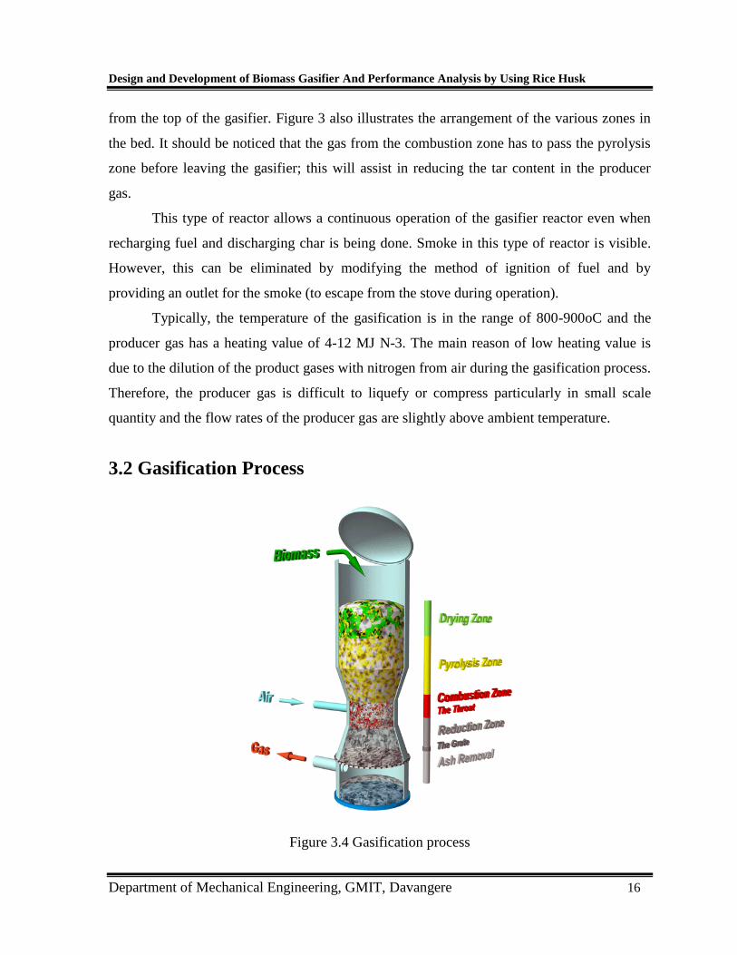
3.2 Gasification Process
Figure 3.4 Gasification process

Design and Development of Biomass Gasifier And Performance Analysis by Using Rice Husk
Department of Mechanical Engineering, GMIT, Davangere 17 | P a
Rice husk fuel is fed into the gasifier through the top opening per sample. Air flow is
supplied to the gasifier using an AC fan to provide the air needed by the fuel during the
gasification. Air enters the combustion zone and producer exits near the bottom of the
gasifier. The hot producer gas is allowed to pass through the attached condenser for
condensation as well as for the cooling process. The producer gas then passes through a filter
thereby removing dust particles left in the gasifier during gasification. The cooled producer
gas is then released in the valve opening.
Figure 3.5 Gasification Flow Diagram
Drying Zone: Solid fuel is introduced into the gasifier at the top. It is not necessary to
use complex fuel-feeding equipment, because a small amount of air leakage can be
tolerated at this spot. As a result of heat transfer from the lower parts of the gasifier,
drying of the wood or biomass fuel occurs in the bunker section.
The water vapour will flow downwards and add to the water vapour formed in the
oxidation zone. Part of it may be reduced to and the rest will end up as moisture in the
gas.
Pyrolysis Zone: At temperatures above 250°C, the biomass fuel starts pyrolysing. The
details of these pyrolysis reactions are not well known, but one can surmise that large
molecules (such as cellulose, hemi-cellulose and lignin) break down into medium size
molecules and carbon (char) during the heating of the feedstock. The pyrolysis products
Design and Development of Biomass Gasifier And Performance Analysis by Using Rice Husk
Department of Mechanical Engineering, GMIT, Davangere 18 | P a
flow downwards into the hotter zones of the gasifier. Some will be burned in the
oxidation zone, and the rest will break down to even smaller molecules of hydrogen,
methane, carbon monoxide, ethane, ethylene, etc. if they remain in the hot zone long
enough.
If the residence time in the hot zone is too short or the temperature too low, then
medium sized molecules can escape and will condense as tars and oils, in the low
temperature parts of the system.
Oxidation Zone: A burning (oxidation) zone is formed at the level where oxygen (air) is
introduced. Reactions with oxygen are highly exothermic and result in a sharp rise of the
temperature up to 1200 - 1500 °C.
As mentioned above, an important function of the oxidation zone, apart from heat
generation, is to convert and oxidize virtually all condensable products from the pyrolysis
zone. In order to avoid cold spots in the oxidation zone, air inlet velocities and the reactor
geometry must be well chosen.
Generally two methods are employed to obtain an even temperature distribution:
- reducing the cross-sectional area at a certain height of the reactor ("throat" concept),
- spreading the air inlet nozzles over the circumference of the reduced cross-sectional
area, or alternatively using a central air inlet with a suitable spraying device.
Reduction zone: The reaction products of the oxidation zone (hot gases and glowing
charcoal) move downward into the reduction zone.
In this zone the sensible heat of the gases and charcoal is converted as much as
possible into chemical energy of the producer gas. The end product of the chemical
reactions that take place in the reduction zone is a combustible gas which can be used as
fuel gas in burners and after dust removal and cooling is suitable for internal combustion
engines.
The ashes which result from gasification of the biomass should occasionally be
removed from the gasifier. Usually a moveable grate in the bottom of the equipment is
considered necessary. This makes it possible to stir the charcoal bed in the reduction
zone, and thus helps to prevent blockages which can lead to obstruction of the gas flow.

Design and Development of Biomass Gasifier And Performance Analysis by Using Rice Husk
Department of Mechanical Engineering, GMIT, Davangere 19 | P a
Producer gas and its constituents:

Design and Development of Biomass Gasifier And Performance Analysis by Using Rice Husk
Department of Mechanical Engineering, GMIT, Davangere 20
CHAPTER 4
DESCRIPTION OF GASIFIER DESIGN
4.1 Hopper
Figure 4.1 Hopper
The purpose of a hopper is to store the biomass for continuous feed to reaction
chamber. It is mounted above the reactor of gasifier. The fuel storage hopper is made up of
2mm thick mild steel. The diameter and height of fuel hopper is chosen to be 375mm and
637.5mm respectively. Round shaped hopper has been chosen to prevent the problem of
biomass being stuck. 12 holes are drilled below the hopper to cover the reactor with the help
of nut and bolts. Figure 4.1 show the hopper.

Design and Development of Biomass Gasifier And Performance Analysis by Using Rice Husk
Department of Mechanical Engineering, GMIT, Davangere 21
4.2 Reactor
Figure 4.2 Reactor
This is the main component of gasifier. The main reaction of gasification like
oxidation, reduction and distillation takes place in this zone. The diameter and height of
reactor is chosen to be 225mm and 448.5mm respectively. This is shown in Figure 4.2

Design and Development of Biomass Gasifier And Performance Analysis by Using Rice Husk
Department of Mechanical Engineering, GMIT, Davangere 22
4.3 Air Tuyers
Figure 4.3 Air Tuyers
Air-Tuyers are 12-14 mm diameter pipes fixed to the reactor as shown in the figure 4.3.It is
used to fire the biomass initially and it supplies necessary oxygen for the combustion of
biomass in the reactor
4.4 Bottom Shell
Figure 4.4 Bottom shell

Design and Development of Biomass Gasifier And Performance Analysis by Using Rice Husk
Department of Mechanical Engineering, GMIT, Davangere 23
Bottom shell collects all the burnt biomass from the main body. The height and
diameter of bottom shell is 621mm and 225 mm respectively. The bottom shell figure is
shown in figure 4.4.
4.5 Water Seal Tank
Figure 4.5 Water seal tank
The function of the water seal tank is to prevent escape of gas. The height of the
water seal tank is 171mm. The figure of water seal tank is as shown in figure 4.5.

Design and Development of Biomass Gasifier And Performance Analysis by Using Rice Husk
Department of Mechanical Engineering, GMIT, Davangere 24
4.6 Assembly of Gasifier
Figure 4.6 Assembly of Gasifier
Design and Development of Biomass Gasifier And Performance Analysis by Using Rice Husk
Department of Mechanical Engineering, GMIT, Davangere 25
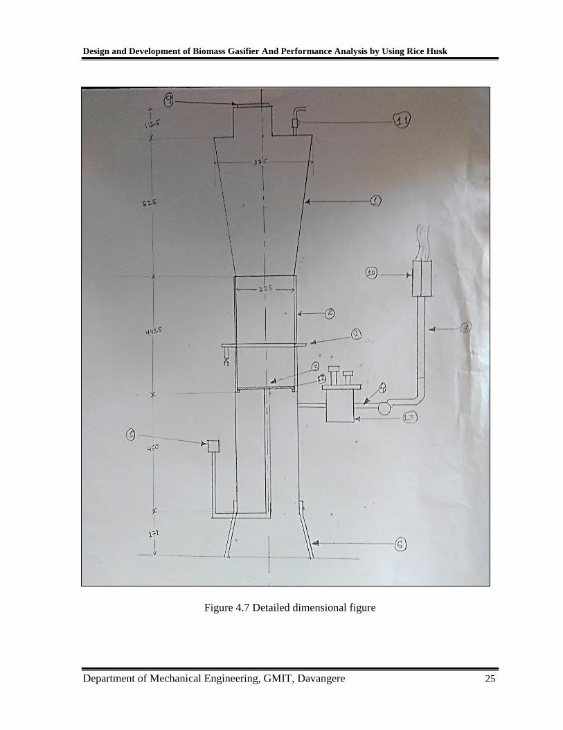
Figure 4.7 Detailed dimensional figure

Design and Development of Biomass Gasifier And Performance Analysis by Using Rice Husk
Department of Mechanical Engineering, GMIT, Davangere 26
Chapter 5
DESIGN OF GASIFIER
In this chapter we will study the design of gasifier which will supply producer gas to run
an 18.77hp or 14KW engine. So In other words we have a 14KW of power requirement
and keeping in this mind we have to design the gasifier.
Fuel used: Rice husk
Types of gasifier: Here we use down draught gasifier (as we already know in case
of down draught gasifier tar content is very less so this is preferred for IC engine
applications).
5.1 Design Calculation for Gasifier
5.1.1 Producer Gas Requirements
This is the first parameter that we have to decide as many other things or to say
entire gasifier design will be based on this.
It is noted or assumed that the producer gas we get from this wood mass will have the
following composition.
Table 5.1: showing composition of producer gas
Now further one cubic meter of gas with above composition will give us 14KWh
[14*3600=50,400KJ]
Constituents Percentage (%)
Carbon monoxide 18-22
Hydrogen 15-19
Methane 1-5
Hydocarbon 0.2-0.4
Nitrogen 45-55
Water 4

Design and Development of Biomass Gasifier And Performance Analysis by Using Rice Husk
Department of Mechanical Engineering, GMIT, Davangere 27
Now in ideal case if we suppose the entire energy in the gas is converted into
mechanical energy then the ideal amount of gas we require to produce 14KW is given by
Gas required =14kw/1kwh/m3of gas
=14 m3/hr.
So ideally we need 14 m3of producer gas per hour however we know that engine
cannot convert entire energy available in the gas into mechanical energy it has its own
conversion efficiency. This implies 1 m3of gas is worth only 1*0.2KWh=0.2KWh
Therefore total gas required to produce 14 KW
=14KW/0.2KWh/ m3
=70 m3 /hr.
Therefore we need 70 m3of producer gas per hour to get an output of 14KW
Now because of the very nature of gasification process and various other factors w.k.t
composition producer gas keeps changing. To account and compensate of this we shall
provide 10% excess of producer gas to the engine.
Therefore the new gas required = (1.10 x 70) =77 m3/h
Thus we have arrived at the gas requirement with the following consideration.
Given gas composition.
Energy content 1KWh/STD m3
20% engine efficiency
10% excess gas supplied to account for in the gas composition.
Thus final gas requirement is 77 STD
5.1.2 Fuel Requirement
Now this much amount of gas has to come from the wood. Now we have to
calculate how much of wood is needed to get 77 m3 of gas per hour.
Let us say we have dry fuel or wood with no moisture content this fuel contains 80%
carbon and this will give us 6 STD m3 of gas.

Design and Development of Biomass Gasifier And Performance Analysis by Using Rice Husk
Department of Mechanical Engineering, GMIT, Davangere 28
Now if we assume wet or moisture containing fuel and in this moisture accounts for 10%
of in the gas liberated. Then from 1kg of wet biomass fuel we will get.
6-[(10/100) x6] = 5.4STD m3 of dry gas
Therefore the next parameter we get is the amount of gas liberated when 1kg of wet fuel
is supplied which we got as 5.4STD m3 /kg of wet fuel
Therefore now quantity wet fuel required producing 77STD m3/hr. of gas
= (77 STD m3/hr.)/ (5.4STD m3/kg)
= 14.25kg/hr.

Design and Development of Biomass Gasifier And Performance Analysis by Using Rice Husk
Department of Mechanical Engineering, GMIT, Davangere 29
Chapter 6
EXPERIMENTAL PROCEDURE
In the downdraft gasifier both the rice husk biomass and gas flow downwards
through the reactor before starting the experiments the reaction chamber was filled with
5kg of charcoal. Subsequently the hopper was mounted over the reaction chamber. The
hopper was fed with 7kg of rice husk biomass through the feed door at the top the feed
door was closed after loading the biomass. Sawdust was added fine filter container after
several rounds of manual stirring .The pumps which was turned on from control panel
and the controlled amount of air was allowed to enter into the reaction chamber through
nozzle chamber. The biomass in the gasifier was ignited by bringing diesel/oil dipped
lighted torch on to air nozzles one after another, so that flame is sucked in to combustion
chamber. Gas production was detected at the flare by burning with a kindler. It was
observed that medium heating value gas was generated within 5 minutes from the start of
the gasification process. Heat generated in the combustion chamber propagates to the
Pyrolysis gases to a throated to hot bed of char which supported by a great. This result in
cracking of most of the tars into non condensable gases and water. Furthermore, air is
admitted to the fuel bed through an air intake nozzles causing Pyrolysis to charcoal and
volatiles that partially burns as they are produced. The gases products of this flaming
Pyrolytic combustion then consume the charcoal produced during the Pyrolysis and
drying zone and biomass starts releasing volatiles and covert to char which drops down to
the reduction chamber. Special ash handling mechanism was provided at the bottom of
the reduction zone so that no clinkers can form and it is reduced to fuel gas in this way tar
vapours are typically lowered to 0.1% of total feed. Whereas in draft or cross flow
gasifier, tar levels are higher than 0.1%.This gas is used for operation of internal
combustion engine.