properties of x-rays - stanford university · r = 320 mm. x-ray optics. ... at a certain 2 position...
TRANSCRIPT
Diffractometer
Geometry
Optics
Detectors
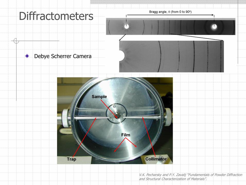
Debye Scherrer Camera
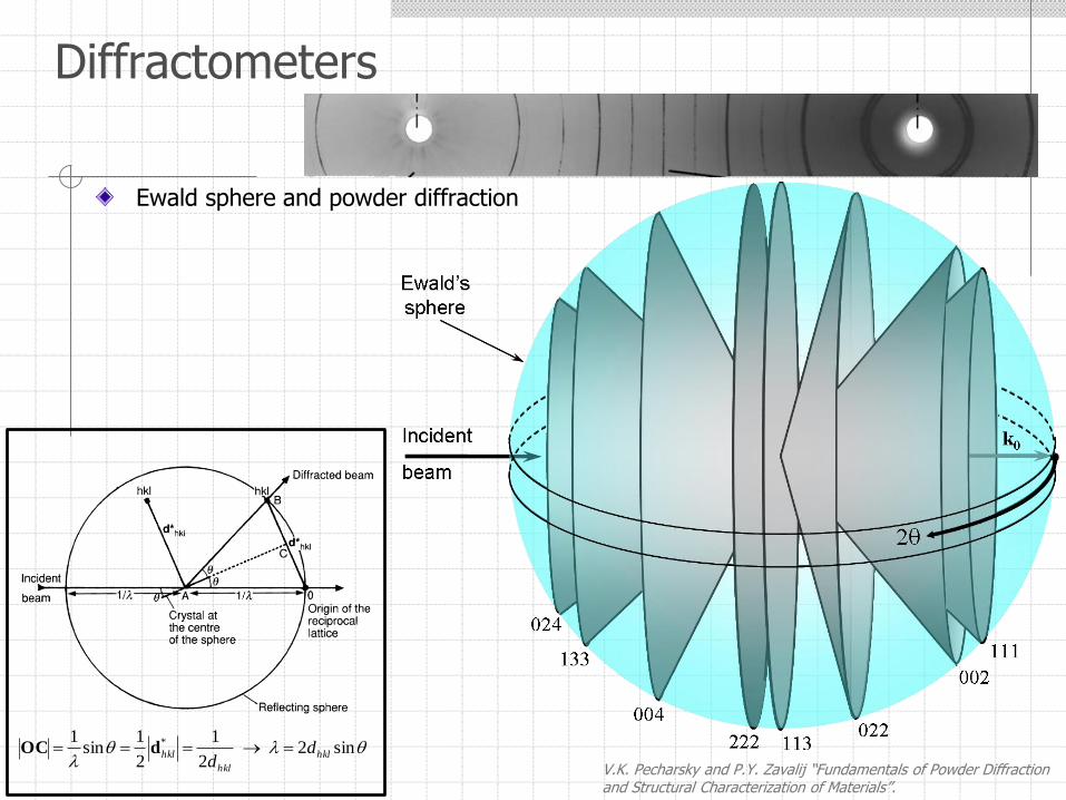
V.K. Pecharsky and P.Y. Zavalij “Fundamentals of Powder Diffraction and Structural Characterization of Materials”.
Diffractometers
Diffractometers
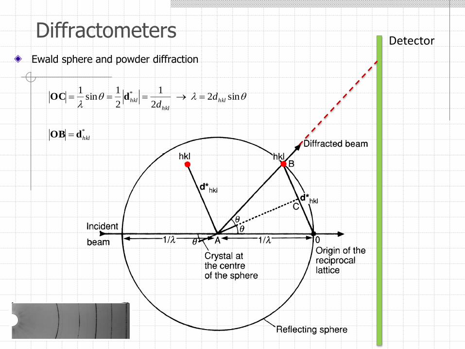
Ewald sphere and powder diffraction
sin22
1
2
1sin
1 *
hkl
hkl
hkl dd
dOC
*
hkldOB
Detector
Diffractometers
V.K. Pecharsky and P.Y. Zavalij “Fundamentals of Powder Diffraction and Structural Characterization of Materials”.
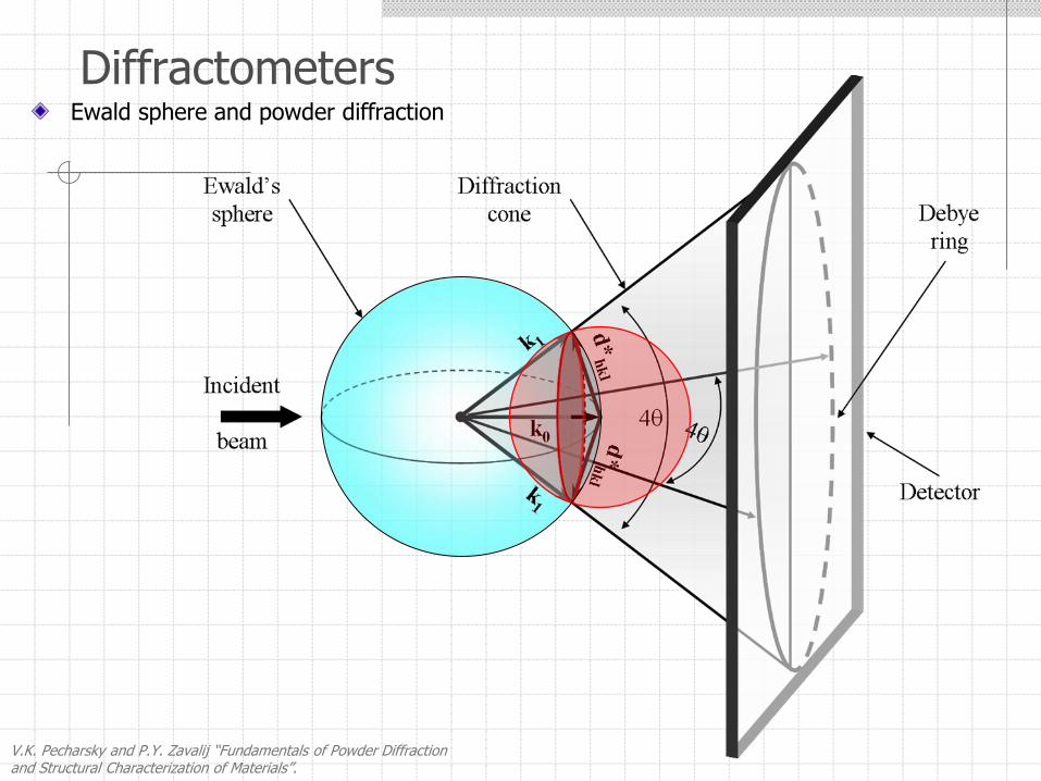
Ewald sphere and powder diffraction
Ewald sphere and powder diffraction
V.K. Pecharsky and P.Y. Zavalij “Fundamentals of Powder Diffraction and Structural Characterization of Materials”.
Diffractometers
sin22
1
2
1sin
1 *
hkl
hkl
hkl dd
dOC
Diffractometers
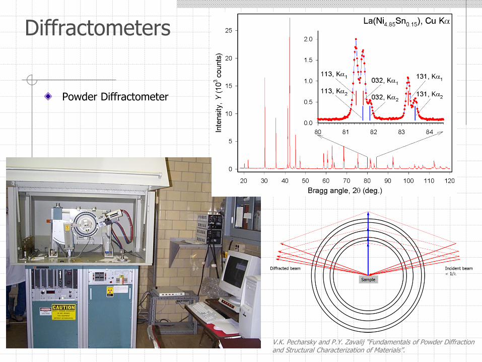
Powder Diffractometer
V.K. Pecharsky and P.Y. Zavalij “Fundamentals of Powder Diffraction and Structural Characterization of Materials”.
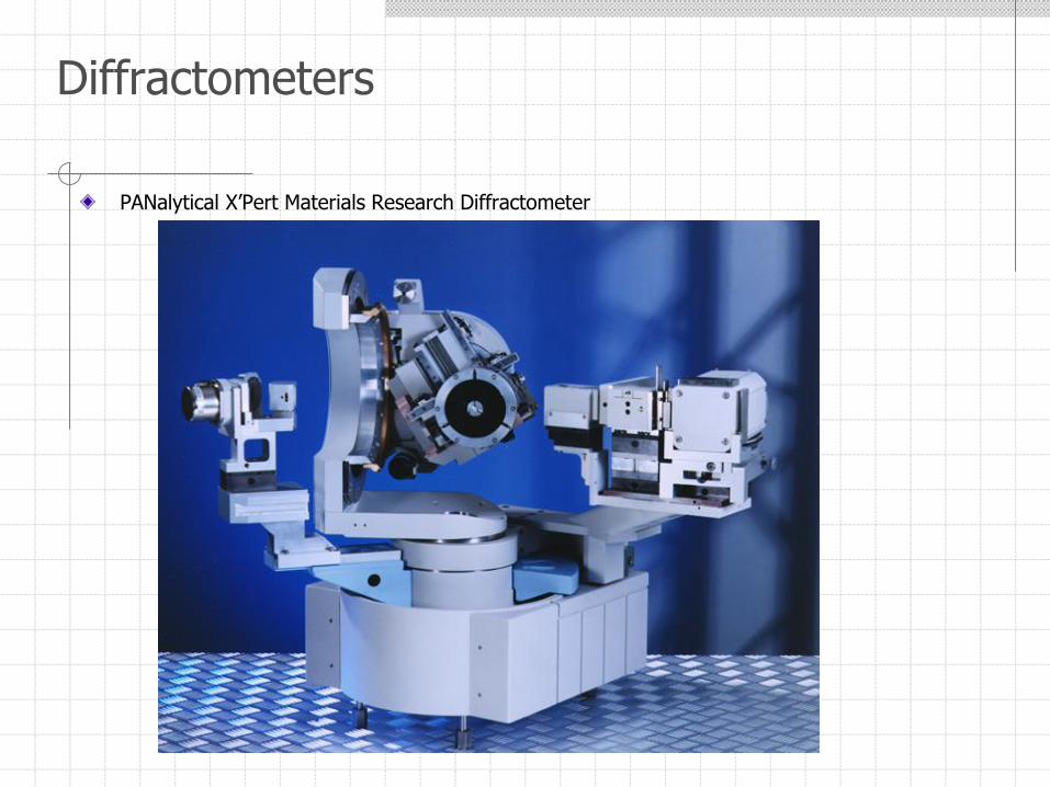
PANalytical X’Pert Materials Research Diffractometer
Diffractometers
X-ray Powder Diffractometer
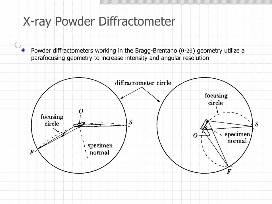
Powder diffractometers working in the Bragg-Brentano (-2) geometry utilize a parafocusing geometry to increase intensity and angular resolution
Diffractometers
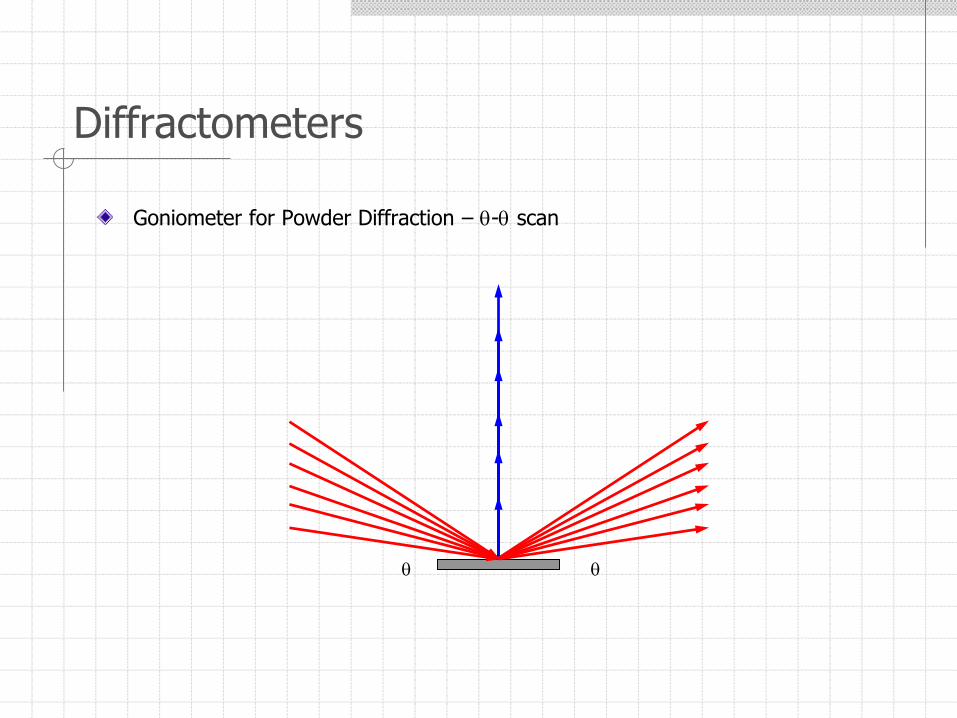
Goniometer for Powder Diffraction – - scan
Diffractometers
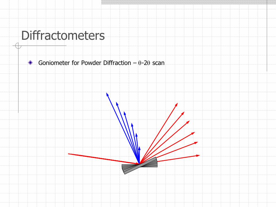
Goniometer for Powder Diffraction – -2 scan
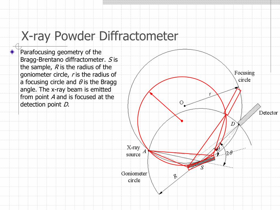
X-ray Powder DiffractometerParafocusing geometry of the Bragg-Brentano diffractometer. S is the sample, R is the radius of the goniometer circle, r is the radius of a focusing circle and θ is the Bragg angle. The x-ray beam is emitted from point A and is focused at the detection point D.
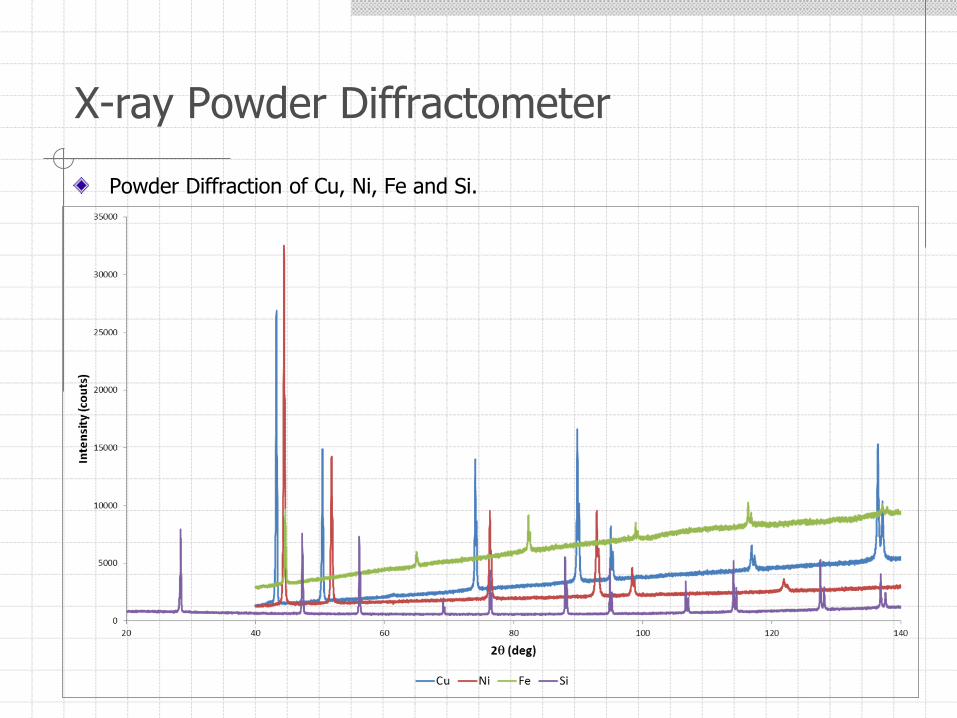
Powder Diffraction of Cu, Ni, Fe and Si.
X-ray Powder Diffractometer
X-ray Powder Diffractometer
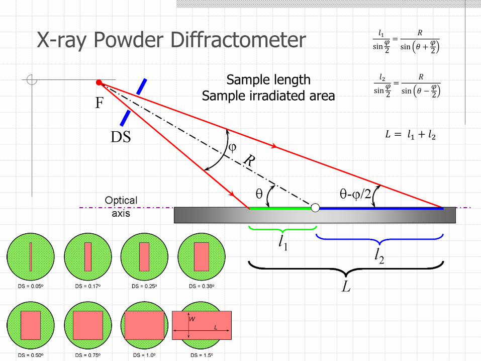
Sample lengthSample irradiated area
𝑙2
sin𝜑2
=𝑅
sin 𝜃 −𝜑2
𝑙1
sin𝜑2
=𝑅
sin 𝜃 +𝜑2
𝐿 = 𝑙1 + 𝑙2
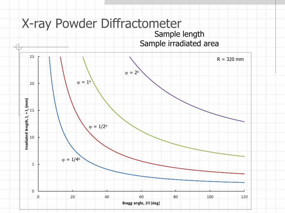
X-ray Powder DiffractometerSample length
Sample irradiated area
= 2o
= 1o
= 1/2o
= 1/4o
R = 320 mm
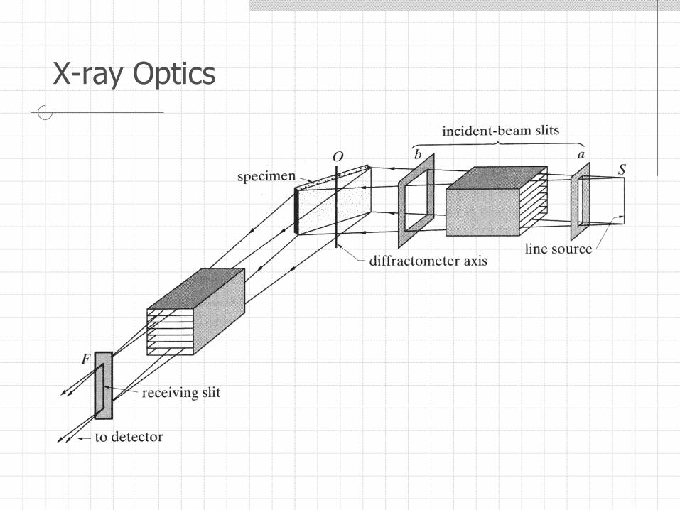
X-ray Optics
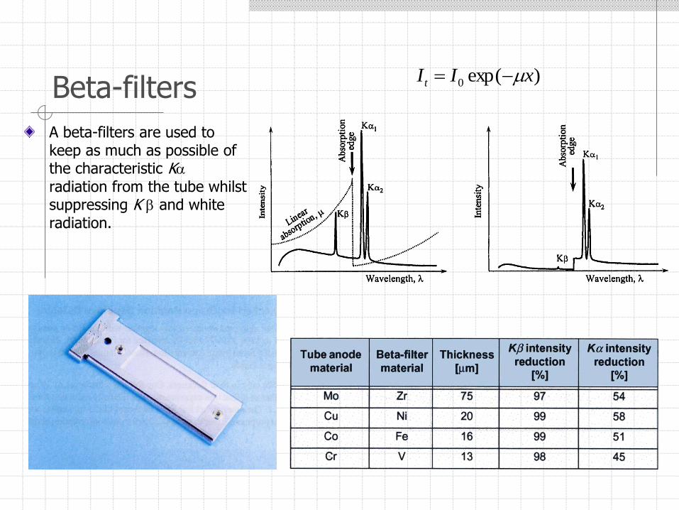
Beta-filters
A beta-filters are used to keep as much as possible of the characteristic Kradiation from the tube whilst suppressing K and white radiation.
)exp(0 xIIt
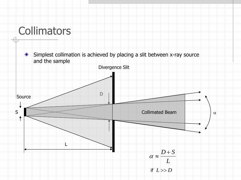
Collimators
Simplest collimation is achieved by placing a slit between x-ray source and the sample
L
SD
S
L
DSource
Divergence Slit
Collimated Beam
if DL
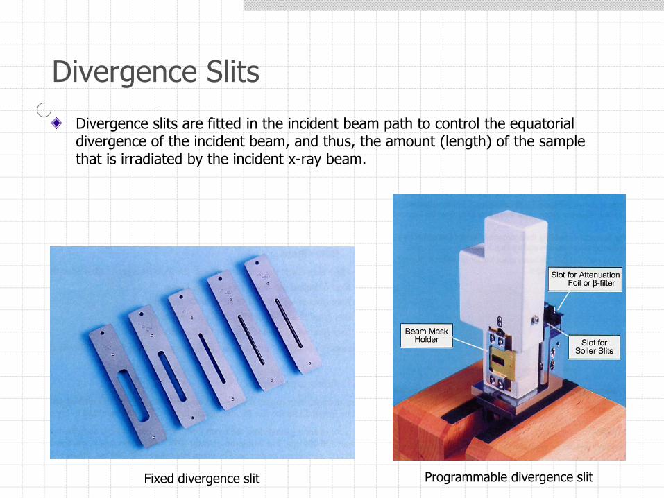
Divergence slits are fitted in the incident beam path to control the equatorial divergence of the incident beam, and thus, the amount (length) of the sample that is irradiated by the incident x-ray beam.
Divergence Slits
Programmable divergence slitFixed divergence slit
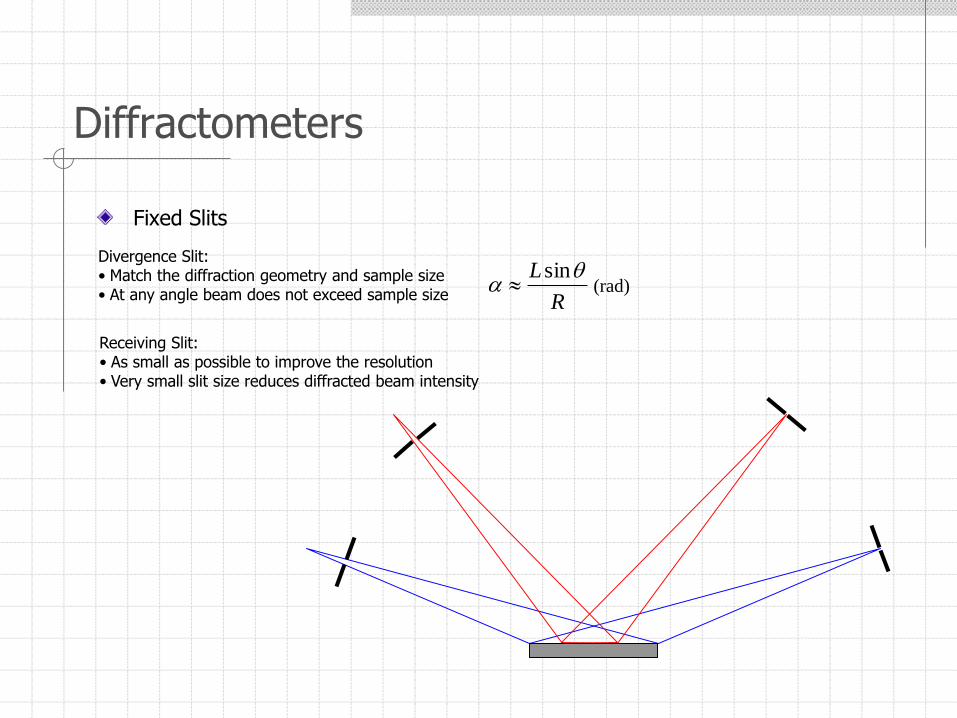
Diffractometers
Fixed Slits
Divergence Slit:• Match the diffraction geometry and sample size• At any angle beam does not exceed sample size R
L
sin (rad)
Receiving Slit:• As small as possible to improve the resolution• Very small slit size reduces diffracted beam intensity
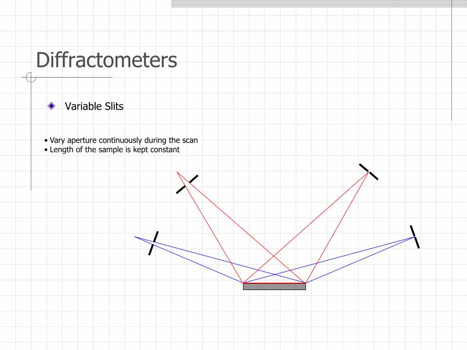
Diffractometers
Variable Slits
• Vary aperture continuously during the scan• Length of the sample is kept constant
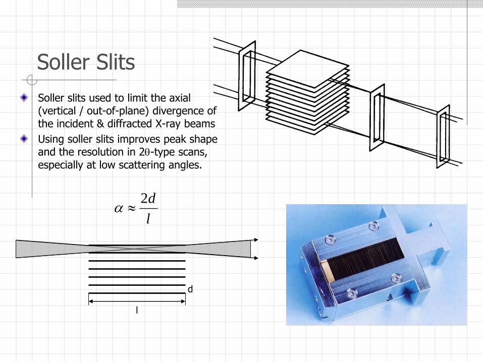
Soller Slits
Soller slits used to limit the axial (vertical / out-of-plane) divergence of the incident & diffracted X-ray beams
Using soller slits improves peak shape and the resolution in 2-type scans, especially at low scattering angles.
d
l
l
d2
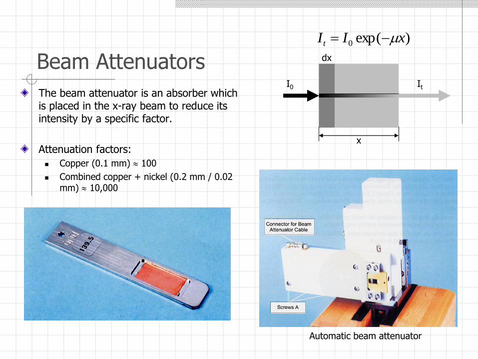
Beam Attenuators
The beam attenuator is an absorber which is placed in the x-ray beam to reduce its intensity by a specific factor.
Attenuation factors:
Copper (0.1 mm) 100
Combined copper + nickel (0.2 mm / 0.02 mm) 10,000
Automatic beam attenuator
)exp(0 xIIt
I0 It
x
dx
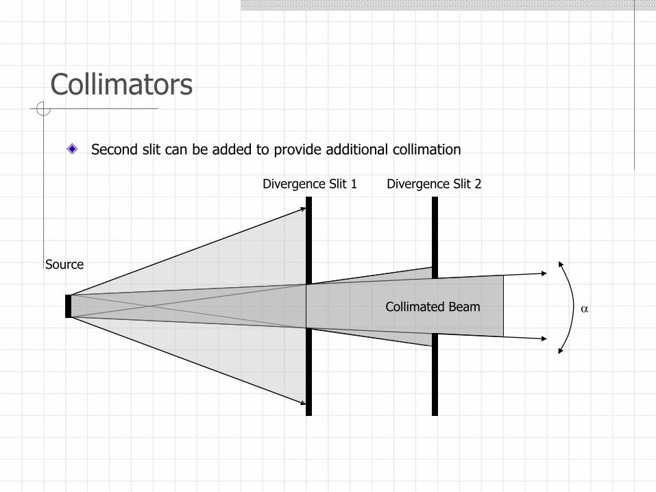
Collimators
Second slit can be added to provide additional collimation
Source
Divergence Slit 1
Collimated Beam
Divergence Slit 2
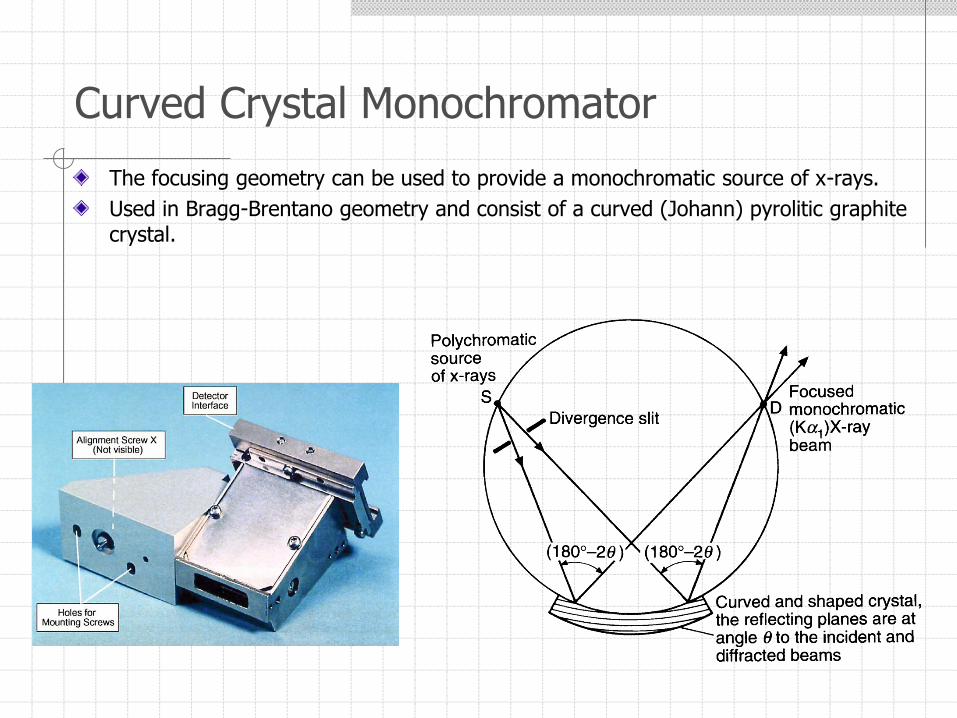
The focusing geometry can be used to provide a monochromatic source of x-rays.
Used in Bragg-Brentano geometry and consist of a curved (Johann) pyrolitic graphite crystal.
Curved Crystal Monochromator
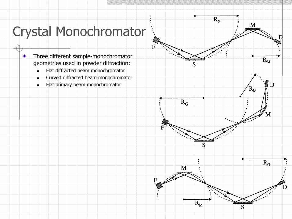
Three different sample-monochromator geometries used in powder diffraction:
Flat diffracted beam monochromator
Curved diffracted beam monochromator
Flat primary beam monochromator
Crystal Monochromator
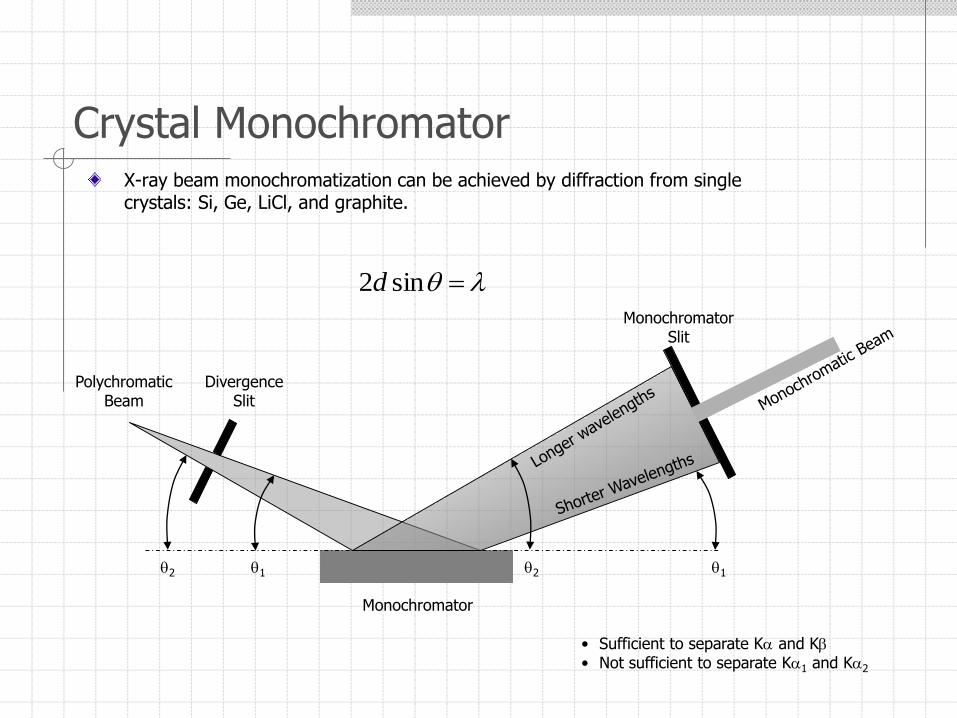
Crystal MonochromatorX-ray beam monochromatization can be achieved by diffraction from single crystals: Si, Ge, LiCl, and graphite.
PolychromaticBeam
DivergenceSlit
MonochromatorSlit
Monochromator
12 12
sin2d
• Sufficient to separate K and K• Not sufficient to separate K1 and K2
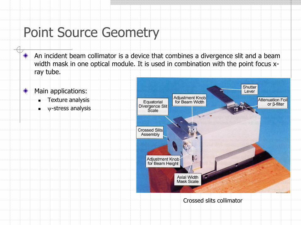
An incident beam collimator is a device that combines a divergence slit and a beam width mask in one optical module. It is used in combination with the point focus x-ray tube.
Main applications:
Texture analysis
-stress analysis
Point Source Geometry
Crossed slits collimator
Point Source Geometry
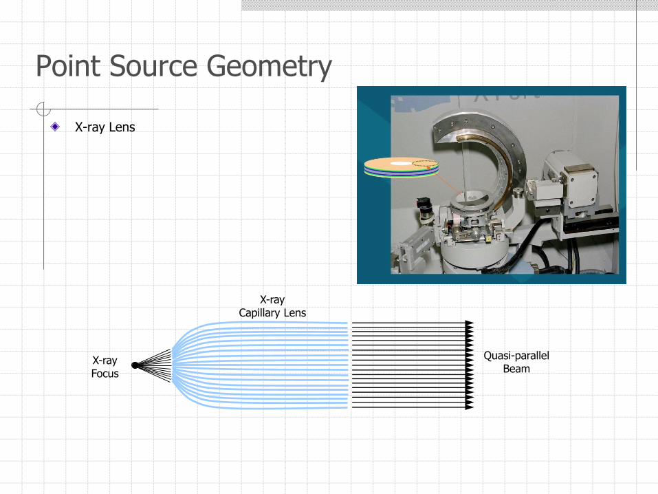
X-ray Lens
Point Source Geometry
X-rayCapillary Lens
X-rayFocus
Quasi-parallelBeam

X-ray Mono-capillary
Used for microdiffraction
Beam sizes 1 mm – 10m
Point Source Geometry
X-rayMono-capillary
X-rayFocus
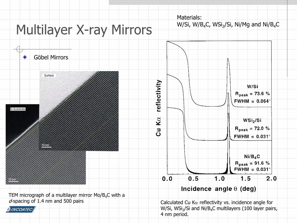
Göbel Mirrors
Multilayer X-ray Mirrors
TEM micrograph of a multilayer mirror Mo/B4C with a d-spacing of 1.4 nm and 500 pairs
Materials:W/Si, W/B4C, WSi2/Si, Ni/Mg and Ni/B4C
Calculated Cu K reflectivity vs. incidence angle for W/Si, WSi2/Si and Ni/B4C multilayers (100 layer pairs, 4 nm period.
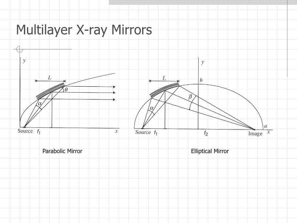
Multilayer X-ray Mirrors
Parabolic Mirror Elliptical Mirror
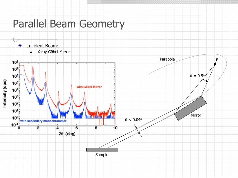
Incident Beam:
X-ray Göbel Mirror
Parallel Beam Geometry
Mirror
Sample
F
= 0.5o
< 0.04o
Parabola
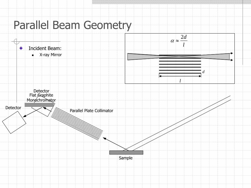
Incident Beam:
X-ray Mirror
Parallel Beam Geometry
Sample
Parallel Plate Collimator
Detector
d
l
l
d2
Detector
Flat GraphiteMonochromator
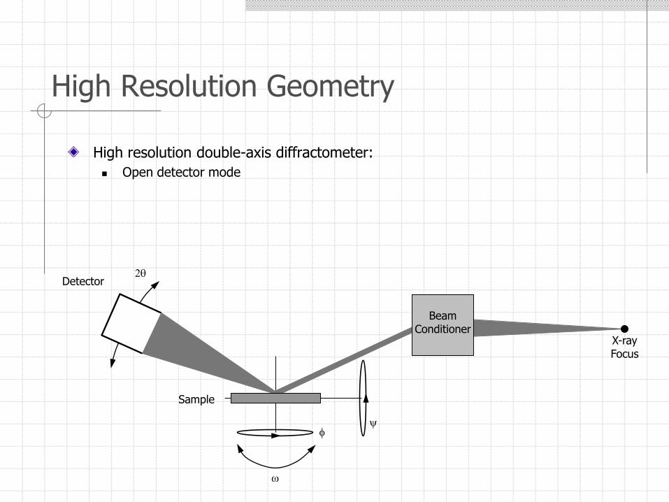
High Resolution Geometry
High resolution double-axis diffractometer:
Open detector mode
BeamConditioner
Sample
Detector
f
w
2
X-rayFocus
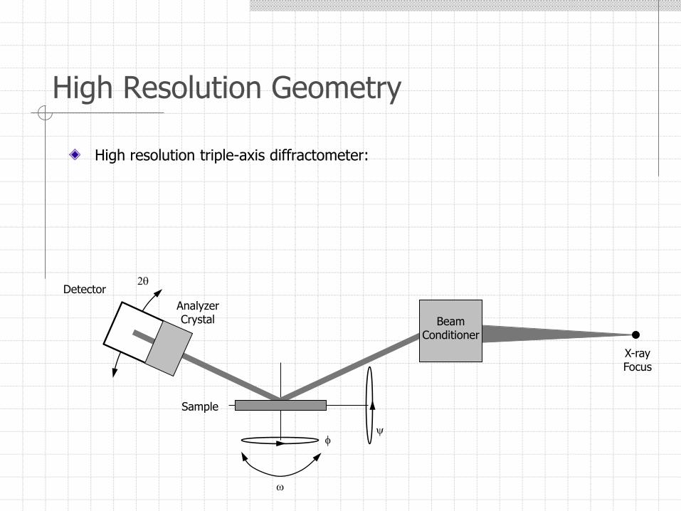
High Resolution Geometry
High resolution triple-axis diffractometer:
BeamConditioner
Sample
Detector
f
w
2
X-rayFocus
AnalyzerCrystal
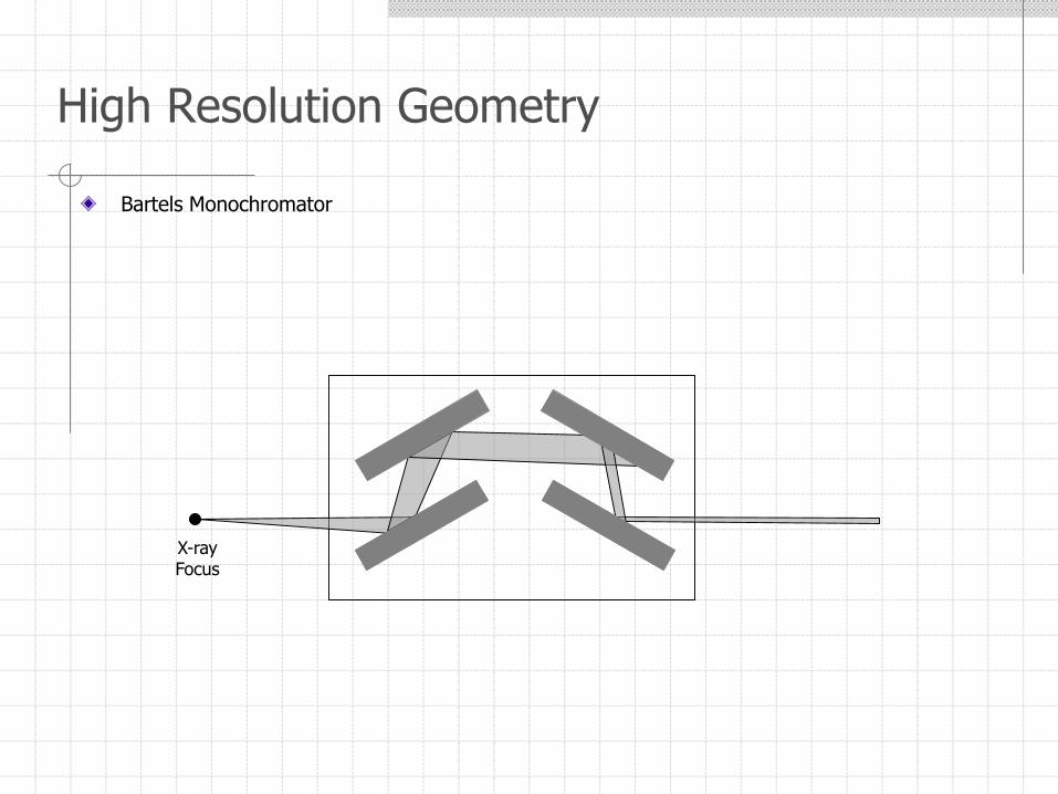
Bartels Monochromator
High Resolution Geometry
X-rayFocus
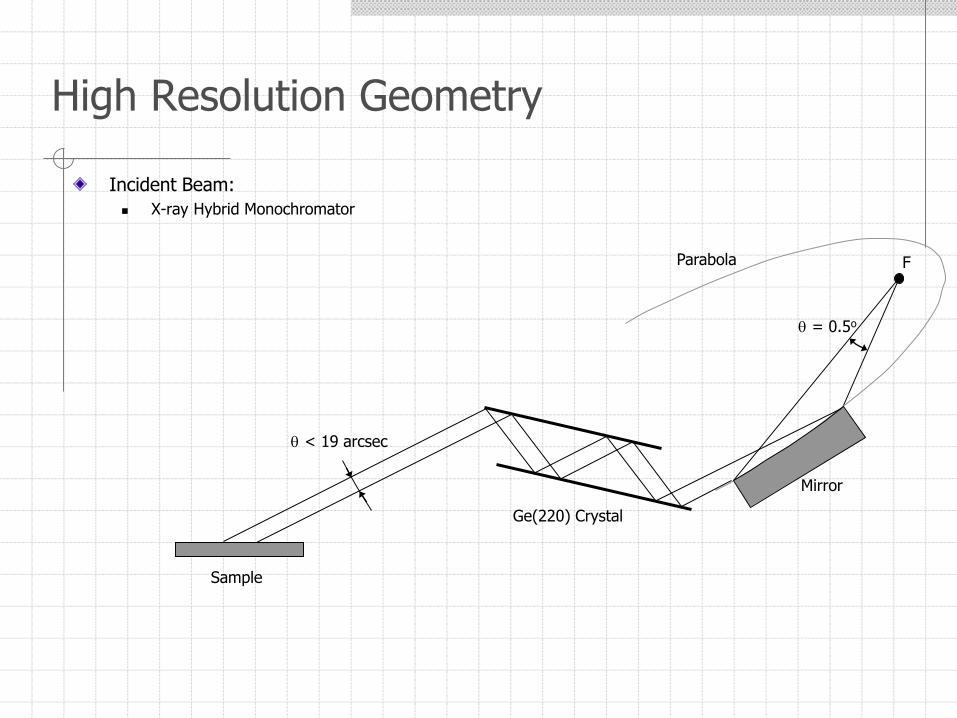
Incident Beam:
X-ray Hybrid Monochromator
High Resolution Geometry
Mirror
Sample
F
= 0.5o
< 19 arcsec
Parabola
Ge(220) Crystal
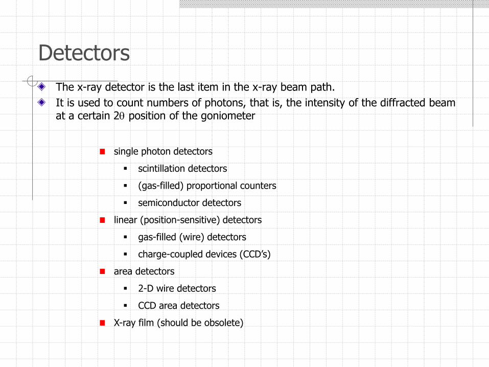
The x-ray detector is the last item in the x-ray beam path.
It is used to count numbers of photons, that is, the intensity of the diffracted beam at a certain 2 position of the goniometer
Detectors
single photon detectors
scintillation detectors
(gas-filled) proportional counters
semiconductor detectors
linear (position-sensitive) detectors
gas-filled (wire) detectors
charge-coupled devices (CCD’s)
area detectors
2-D wire detectors
CCD area detectors
X-ray film (should be obsolete)
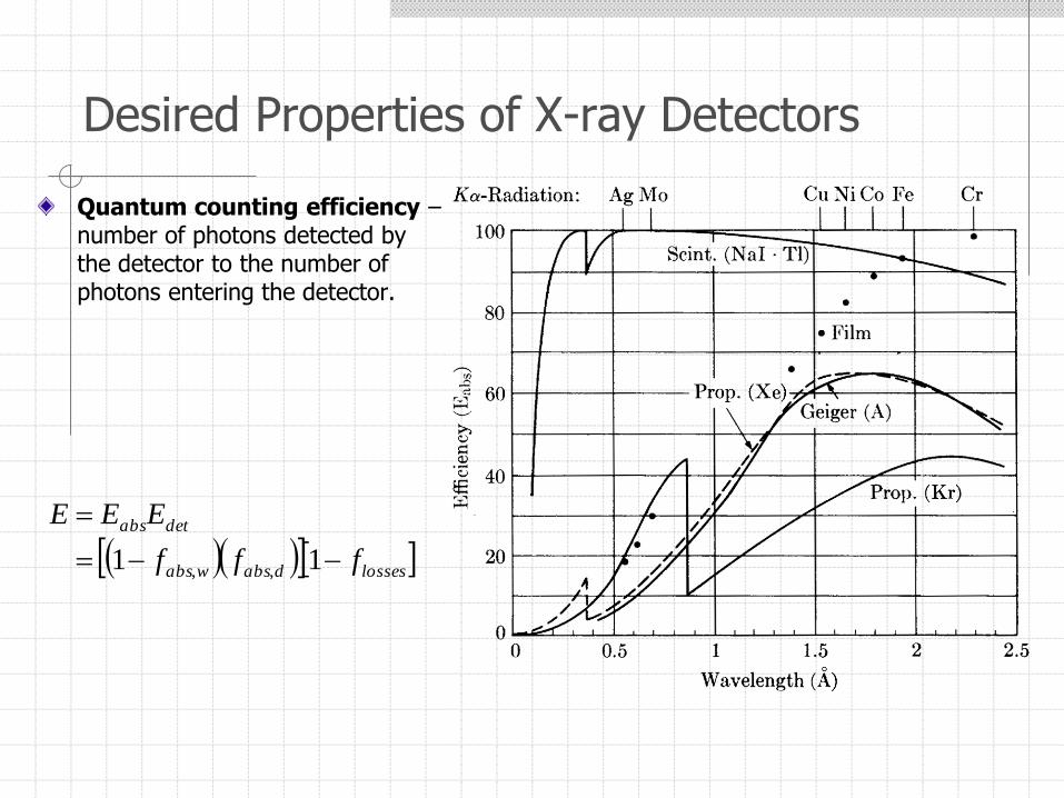
Quantum counting efficiency –number of photons detected by the detector to the number of photons entering the detector.
Desired Properties of X-ray Detectors
lossesdabswabs
detabs
fff
EEE
11 ,,
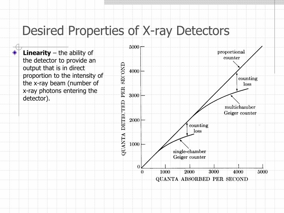
Linearity – the ability of the detector to provide an output that is in direct proportion to the intensity of the x-ray beam (number of x-ray photons entering the detector).
Desired Properties of X-ray Detectors
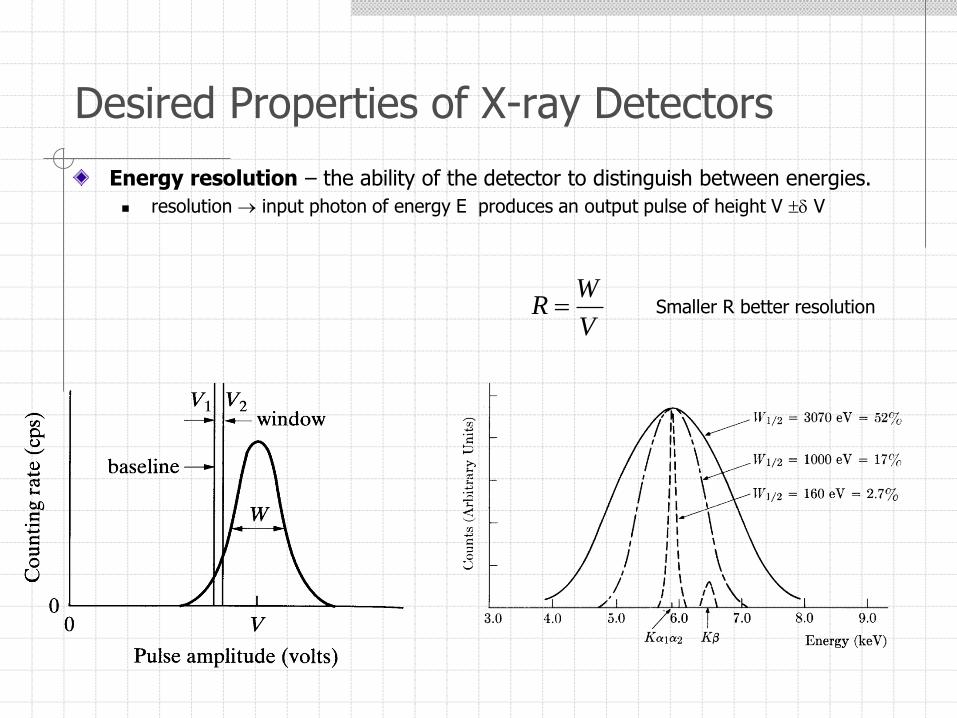
Energy resolution – the ability of the detector to distinguish between energies.
resolution input photon of energy E produces an output pulse of height V V
Desired Properties of X-ray Detectors
V
WR Smaller R better resolution
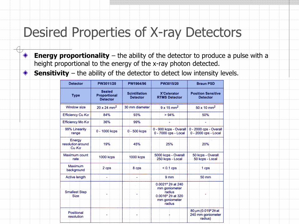
Energy proportionality – the ability of the detector to produce a pulse with a height proportional to the energy of the x-ray photon detected.
Sensitivity – the ability of the detector to detect low intensity levels.
Desired Properties of X-ray Detectors
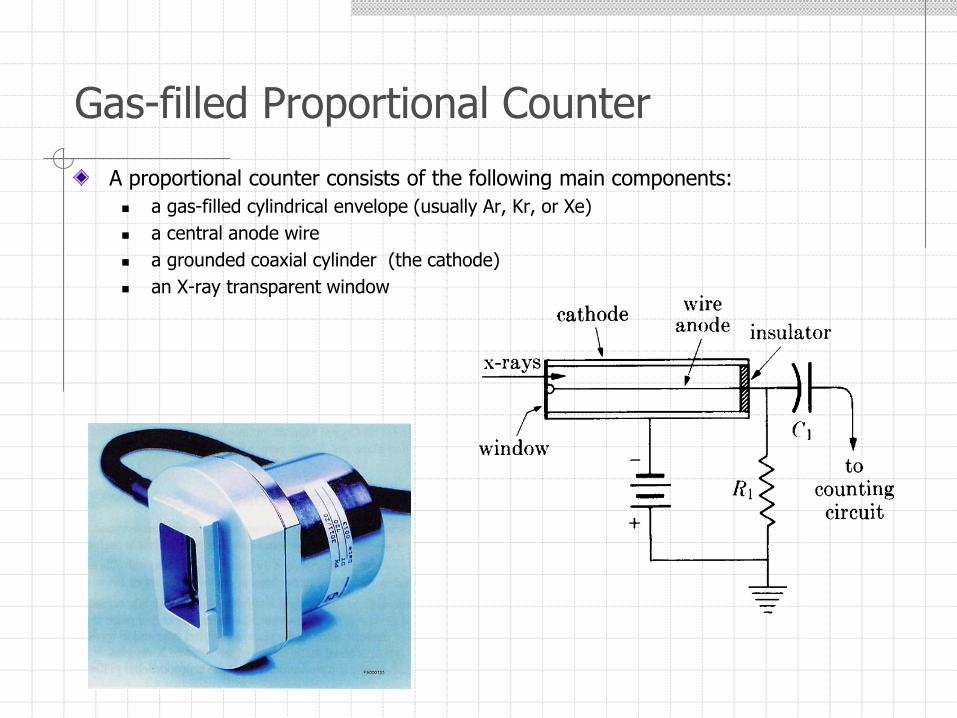
A proportional counter consists of the following main components:
a gas-filled cylindrical envelope (usually Ar, Kr, or Xe)
a central anode wire
a grounded coaxial cylinder (the cathode)
an X-ray transparent window
Gas-filled Proportional Counter
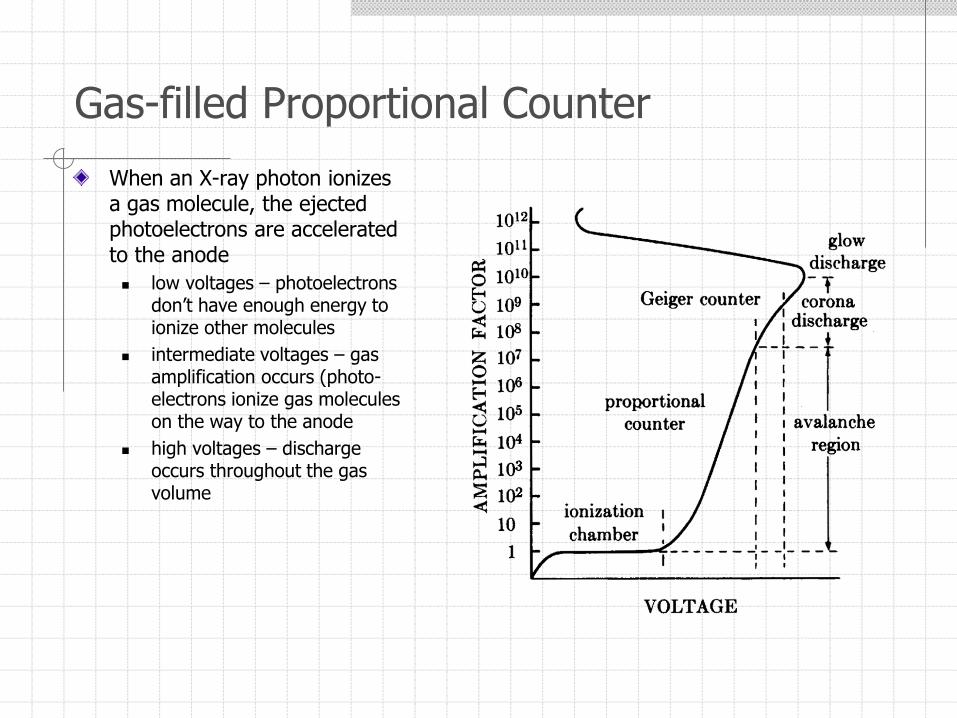
When an X-ray photon ionizes a gas molecule, the ejected photoelectrons are accelerated to the anode
low voltages – photoelectrons don’t have enough energy to ionize other molecules
intermediate voltages – gas amplification occurs (photo-electrons ionize gas molecules on the way to the anode
high voltages – discharge occurs throughout the gas volume
Gas-filled Proportional Counter
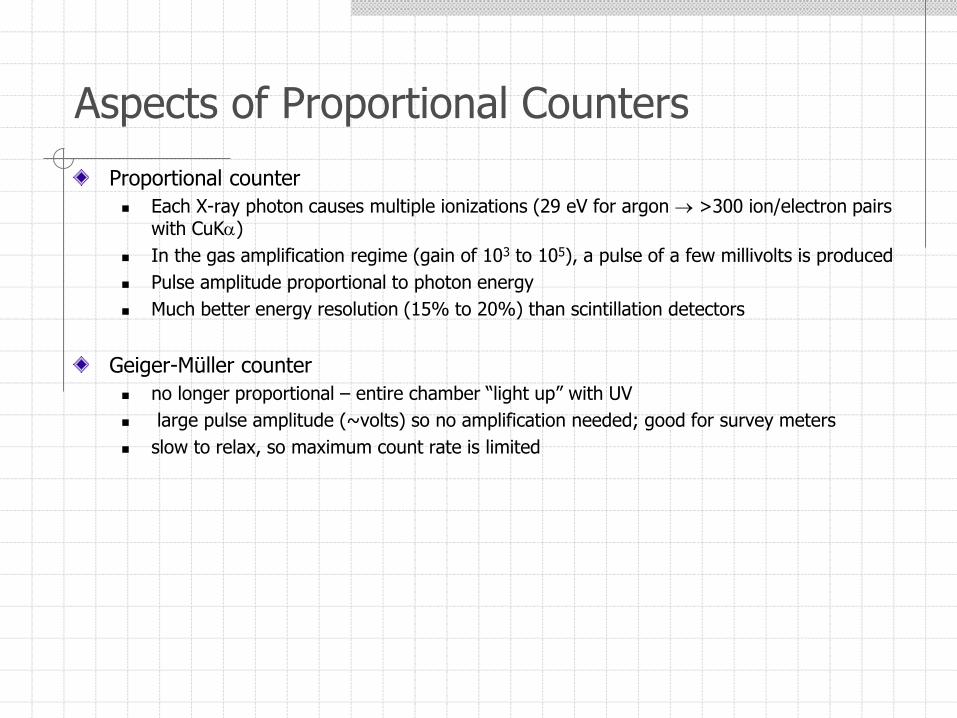
Proportional counter
Each X-ray photon causes multiple ionizations (29 eV for argon >300 ion/electron pairs with CuK)
In the gas amplification regime (gain of 103 to 105), a pulse of a few millivolts is produced
Pulse amplitude proportional to photon energy
Much better energy resolution (15% to 20%) than scintillation detectors
Geiger-Müller counter
no longer proportional – entire chamber “light up” with UV
large pulse amplitude (~volts) so no amplification needed; good for survey meters
slow to relax, so maximum count rate is limited
Aspects of Proportional Counters
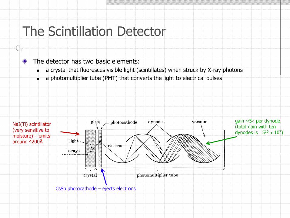
The detector has two basic elements:
a crystal that fluoresces visible light (scintillates) when struck by X-ray photons
a photomultiplier tube (PMT) that converts the light to electrical pulses
The Scintillation Detector
NaI(Tl) scintillator(very sensitive to moisture) – emitsaround 4200Å
CsSb photocathode – ejects electrons
gain ~5 per dynode (total gain with ten dynodes is 510 107)
Relatively inexpensive (~$1500) and rugged
All necessary electronics are “off the shelf”
Scintillator crystal can develop “dead spots” over time
NaI is very hydroscopic and needs careful encapsulation
Sealed from ambient light with thin Be window
Energy resolution is poor (~50%)
Typical noise of < 1 count/sec; advanced detectors can be linear in excess of 106
counts/sec
Aspects of Scintillation Detectors
Aspects of Semiconductor Detectors
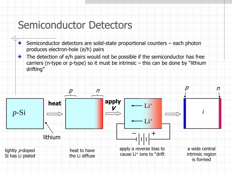
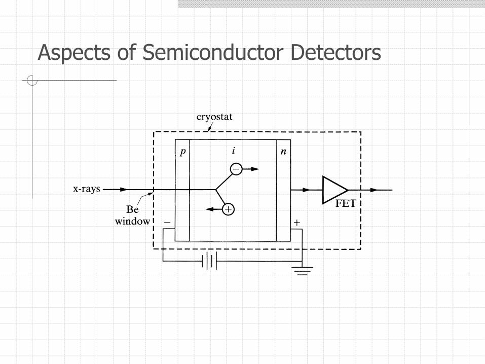
Semiconductor detectors are solid-state proportional counters – each photon produces electron-hole (e/h) pairs
The detection of e/h pairs would not be possible if the semiconductor has free carriers (n-type or p-type) so it must be intrinsic – this can be done by “lithium drifting”
Semiconductor Detectors
p-SiLi+
Li+
lithium
heat applyV
lightly p-dopedSi has Li plated
heat to havethe Li diffuse
apply a reverse bias to cause Li+ ions to “drift
np np
i
a wide centralintrinsic region
is formed
Originally: Si(Li) and Ge(Li) – “silly” and “jelly”
Now intrinsic Si and intrinsic Ge are available (Ge better due to higher absorption and better energy resolution)
Energy resolution about 2%
Small signal requires a charge-sensitive preamp integrated with the detector
due to thermal e/h generation and noise in the preamp, cooling to 77K is needed
New detectors use Si p-i-n photodiodes and large bandgap materials (CdTe and CdZnTe) for room-temperature operation
Aspects of Semiconductor Detectors
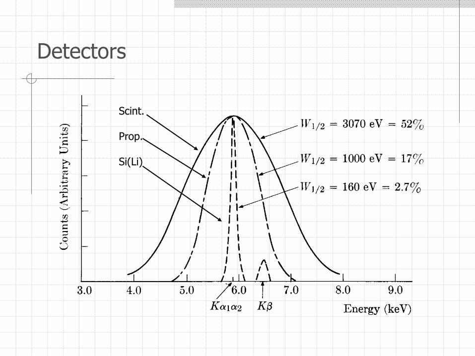
Detectors
Scint.
Prop.
Si(Li)
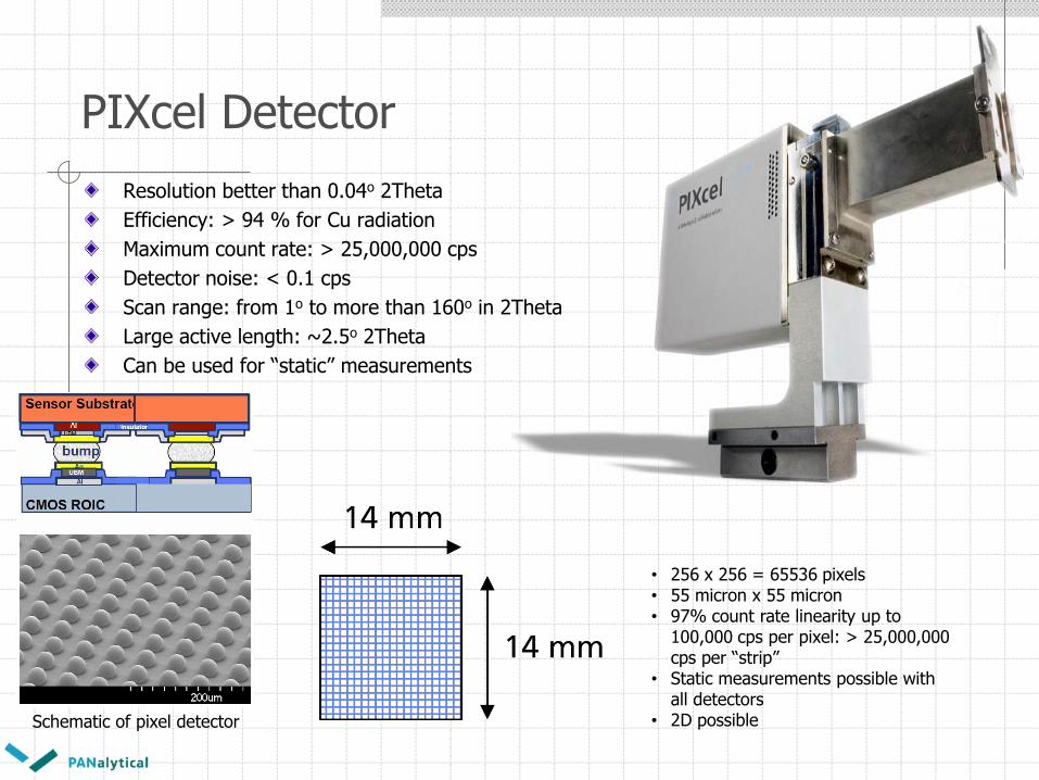
PIXcel Detector
Resolution better than 0.04o 2Theta
Efficiency: > 94 % for Cu radiation
Maximum count rate: > 25,000,000 cps
Detector noise: < 0.1 cps
Scan range: from 1o to more than 160o in 2Theta
Large active length: ~2.5o 2Theta
Can be used for “static” measurements
Schematic of pixel detector
• 256 x 256 = 65536 pixels• 55 micron x 55 micron• 97% count rate linearity up to
100,000 cps per pixel: > 25,000,000 cps per “strip”
• Static measurements possible with all detectors
• 2D possible
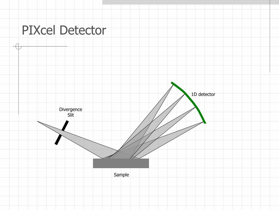
PIXcel Detector
DivergenceSlit
Sample
1D detector
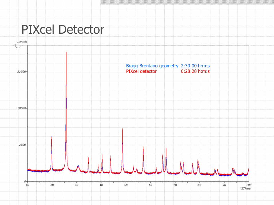
PIXcel Detector
Bragg-Brentano geometry 2:30:00 h:m:sPIXcel detector 0:28:28 h:m:s
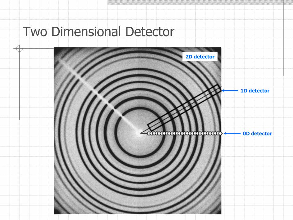
Two Dimensional Detector
0D detector
1D detector
2D detector