property damage! retain instructions for future reference ... oil if the forks/platform won’t...
TRANSCRIPT

Form 5S6382
ENGLISH
ESPAÑOL
FRANÇAIS
Printed in U.S.A.096670309/063/VCPVP
NOB100403
General Safety InformationOnly authorized and trained operatorsshould use this product.
Never exceed themaximum capacity
of the lift. Load must be evenlydistributed and load center limits must not be exceeded.
Use caution and beaware of pinch and
crush points. Never place hands, feet,or objects under forks or platform.Never reach into moving parts.
Do not use oninclines or uneven
surfaces.
Never leave the load unattended
in a raised position.
Transporting orlifting persons
is not permitted.
AssemblyYour Dayton Fork or Platform Lift comes fully assembled. Inspect the liftfor transit damage before operation.Refer to the replacement partsillustration and list in identifying parts. If damage is evident, notify deliveringcarrier immediately and file necessaryclaims.
Carefully read all manuals included withthis product before putting into service.Never exceed the maximum capacity of the lift.
Fully read and follow the instructionsfor “Releasing air from the pump” inthe Maintenance section of this manualbefore putting your Dayton lift intoservice.
OperationInspect the lift prior to each use. Discontinue use immediately if anyproblems, defects, or repair needs are discovered.
Pre-operation check list:
– Check the function of all moving parts,including rollers, wheels, axles, etc.
– If your lift is equipped with a parkingbrake, check the function of theparking brake.
– Check load chain for adjustment,tension, and wear.
Dayton® Fork andPlatform Lifts
Operating Instructions & Parts Manual 2MPU5 thru 2MPU9
Please read and save these instructions. Read carefully before attempting to assemble, install, operate or maintain the product described.Protect yourself and others by observing all safety information. Failure to comply with instructions could result in personal injury and/orproperty damage! Retain instructions for future reference.
DescriptionDayton Fork and Platform Lifts are designed for manual lifting, lowering, andtransporting of loads on firm and level surfaces, including workshops, warehouses,stockrooms, receiving departments, throughout a plant, and wherever aisles andcongested areas prevent the use of larger equipment.
Specifications for multiple types of lifts may be described in these OperatingInstructions. During operation and maintenance, apply the relevant aspects for the Dayton Fork Lift or Platform Lift that you have purchased.
2MPU5 Platform Lift 750 54” 1/2” 22” 22” 35” 22.5” 60.5” 12” 2 wheels2MPU6 Platform Lift 750 54 5.75 22 30 35 30 60.5 12 2 wheels2MPU7 Platform Lift 750 54 5.75 22 22 37 22.5 60.5 12 2 wheels,
2 swivel casters2MPU8 Platform Lift 750 54 5.75 22 30 37 30 60.5 12 2 wheels,
2 swivel casters2MPU9 Fork Lift 750 54 1/2 18 N/A 32 22.5 60.5 10 2 wheels
(*) Maximum load capacity rating is for evenly distributed load.(**) Read and understand load center restrictions.
SpecificationsLoad Max. Min. Platform/Cap.* Lifting Lifting Fork Platform Overall Overall Overall Load
Model Item (lbs.) Height Height Length Width Length Width Height Center** Wheels
Figure 1

2
ENGLISH
Operation (Continued)FOR LIFTS EQUIPPED WITH APARKING BRAKE
Utilize the parking brake when placingloads, elevating loads, and when lift is not in use. Activate the brake for each wheel by pressing the appropriatepedal forward. Release the brakes by pressing pedal backward.
LIFTING A LOAD
Ensure that the load does not exceedthe capacity of the lift, and that theload does not exceed the size of theforks or platform.
Roll the lift slowly up to the load andposition the forks under the pallet/loaduntil the back of the forks rests againstthe load, or manually place the loadonto the platform or forks.
Do not load the lift in its raised
position. The load must be evenlydistributed across both forks or acrossthe platform. The load center of gravity must not be exceeded.
Raise the load by pumping the footpedal until it reaches the desired height.
MOVING A LOAD
The load should be in lowest possibleposition (while still maintainingclearance under the load) whenevertransporting a load.
Travel at a steady speed, being mindfulof the load and the floor conditions.
Do not operate thelift on gradients
or uneven surfaces.
LOWERING A LOAD
Maneuver the load to its desiredlocation and actuate the parking brake.Ensure there is nothing under the load,then turn the release valve counter-clockwise to lower the load to thedesired height. Turn the valve slowly to control the speed of descent.
Lower completely when not in use.
MaintenanceRemove loadsbefore performing
inspection or maintenance work. Only use genuine spare parts.
ADDING OIL
If the forks/platform won’t raise to the rated height, you may need to addhydraulic fluid. Hydraulic fluid must beISO VG32 or equivalent with a viscosityof 30cSt at 104°F (40°C). Mixing ofdifferent fluids is prohibited! Total oilvolume is about 2 quarts. Check the oil level every six months.
NOTE: Waste oil must be disposed of inan environmentally-friendly way and inaccordance with regulatory authorities.
LUBRICATION
Periodically lubricate all grease fittingsaccording to the required maintenanceschedule, or after any thorough cleaningthat may excessively remove grease fromcritical lube points, using multipurposelubricating grease ZG2# or 3#.
RELEASING AIR FROM THE PUMP
Air may enter the hydraulic oil duringtransportation or if the unit is tipped,such that the forks don’t elevateimmediately while pumping in the “raise” position. To release air from the pump, turn the release valve counterclockwise to the “lower”position and pump the foot pedalseveral times.
DAILY INSPECTION ANDMAINTENANCE
Daily inspection of the lift can greatlyreduce wear and maintenance. Specialattention should be paid to the wheels,casters, and carriage rollers, inspectingfor obstructions of any kind.
Dayton® Fork and Platform Lifts2MPU5 thru 2MPU9Dayton Operating Instructions and Parts Manual
Figure 2
LowerLift

3
ENGLISH
Maintenance (Continued)RECOMMENDED MAINTENANCEINTERVALS
The service life of your lift is limited.Worn parts must be replaced promptly.
DAILY:
- Check moving parts and operatingcontrols for proper operation
- Check wheels and carriage rollers for wear or slop
- Check load chain for adjustment,tension, and wear
- Grease the chain if necessary
1 MONTH:
- Grease joints and bearings
- Check function and turning capabilityof wheels and rollers
- Check hydraulic system for leakageand full range of motion
3 MONTHS:
- Check hydraulic oil level withplatform/forks fully lowered and thelift in a horizontal position
- Check the release valve adjustment
- Check all screw and bolt connectionsfor tightness
1 YEAR:
- Check all parts for wear and replacedefective parts as necessary
- Drain and replace hydraulic fluid
- Check readability of labels and safetywarnings; replace if needed
Do not attempt torepair lifts unless
you are trained and authorized to doso. Serious injury could result.
These products maynot be altered in
any way without written permissionfrom the manufacturer.
Models 2MPU5 thru 2MPU9Dayton Operating Instructions and Parts Manual

4
ENGLISH
Notes2MPU5 thru 2MPU9Dayton Operating Instructions and Parts Manual

5
ENGLISH
Models 2MPU5 thru 2MPU9Dayton Operating Instructions and Parts Manual
Symptom Possible Cause(s) Corrective Action
Forks/platform doesn’t raise, doesn’t raise fully, or raises slowly
Forks/platform doesn’tlower or doesn’t lower fully
Forks/platform lowerwithout turning the control lever to the “lower” position
1. Low hydraulic fluid level
2. Air in the hydraulic system
3. Release valve handle (54) is stuck in the wrong position (See Figure 6)
4. Load is too heavy. Overload release valveis being activated
5. Temperature is too low and the hydraulicoil has become too thick
1. Obstacle located under forks/platform, in fork mechanism, etc
2. The piston rod (1) or pump (5) hasdeformed from excess or uneven loading(See Figure 6)
3. Forks/platform was kept in the raisedposition for a long time, allowing thepiston rod to rust or jam
4. Release valve handle set screw (53) hasbecome loose (See Figure 6)
1. Oil impurities are preventing the releasevalve from fully closing
2. Some hydraulic components or seals arecracked or worn
3. Air in the hydraulic system
4. Release valve handle (54) is stuck in the wrong position (See Figure 6)
1. Add approved hydraulic fluid as noted onpage 2 (in Maintenance section)
2. Follow the procedure for releasing air fromthe pump on page 2 (in Maintenancesection)
3. Unstick and turn release control handle (54)to the right position
4. Reduce load
5. Move truck to a warmer location
1. Use caution removing the obstacle
2. Replace the piston rod (1) or pump (5)(See Figure 6)
3. Lubricate the piston. Replace if necessary.Keep the forks/platform in the loweredposition when not in use
4. Tighten the screw (53) (See Figure 6)
1. Drain and replace hydraulic fluid withapproved fluid as noted on page 2 (in Maintenance section)
2. Inspect and replace components as needed
3. Follow the procedure for releasing air fromthe pump on page 2 (in Maintenancesection)
4. Unstick and turn release control handle (54)to the right position (See Figure 6)
Troubleshooting Chart

6
ENGLISH
ENGLISH
2MPU5 and 2MPU6Dayton Operating Instructions and Parts Manual
For Repair Parts, call 1-800-323-062024 hours a day – 365 days a yearPlease provide following information:-Model number-Serial number (if any)-Part description and number as shown in parts list
Figure 3 – Repair Parts Illustration for Platform Lift
16
15
2
4
32
25
3 39
10
2728
29
38
34
1213
1535
36
40
24
11
17
1819
12
26
21
23
22
33
30
31
20
67
8
9
14
15
12
1312
37
7
ENGLISH
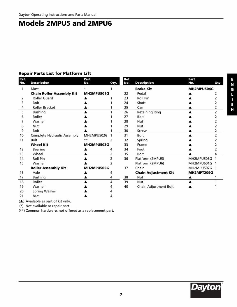
Models 2MPU5 and 2MPU6Dayton Operating Instructions and Parts Manual
Repair Parts List for Platform Lift
1 Mast * 1Chain Roller Assembly Kit MH2MPU501G
2 Roller Guard p 13 Bolt p 14 Roller Bracket p 15 Bushing p 16 Roller p 17 Washer p 18 Nut p 19 Bolt p 1
10 Complete Hydraulic Assembly MH2MPU502G 111 Bolt ** 2
Wheel Kit MH2MPU503G12 Bearing p 413 Wheel p 214 Roll Pin p 215 Washer p 2
Roller Assembly Kit MH2MPU505G16 Axle p 417 Bushing p 418 Roller p 419 Washer p 420 Spring Washer p 421 Nut p 4
Brake Kit MH2MPU504G22 Pedal p 223 Roll Pin p 224 Shaft p 225 Cam p 226 Retaining Ring p 227 Bolt p 228 Nut p 229 Nut p 230 Screw p 231 Bolt p 232 Spring p 233 Frame p 234 Foot p 235 Bolt p 436 Platform (2MPU5) MH2MPU506G 1
Platform (2MPU6) MH2MPU601G 137 Chain MH2MPU507G 1
Chain Adjustment Kit MH2MPT209G38 Nut p 139 Nut p 140 Chain Adjustment Bolt p 1
Ref. Part No. Description No. Qty.
Ref. Part No. Description No. Qty.
(p) Available as part of kit only.(*) Not available as repair part.(**) Common hardware, not offered as a replacement part.

8
ENGLISH
ENGLISH
2MPU7 and 2MPU8Dayton Operating Instructions and Parts Manual
For Repair Parts, call 1-800-323-062024 hours a day – 365 days a yearPlease provide following information:-Model number-Serial number (if any)-Part description and number as shown in parts list
Figure 4 – Repair Parts Illustration for Platform Lift
16
1
5
2
4
32
25
3
39
11
2728
29
38
34
15
35
36
40
24
10
1718
19
26
21
23
22
33
30
31
20
67
8
9
12
13
37
42
43
41
14
9
ENGLISH
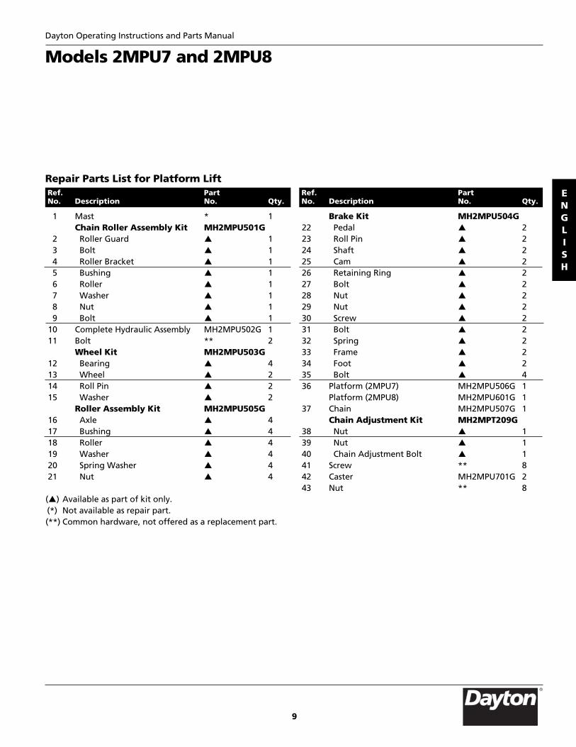
Models 2MPU7 and 2MPU8Dayton Operating Instructions and Parts Manual
Repair Parts List for Platform Lift
1 Mast * 1Chain Roller Assembly Kit MH2MPU501G
2 Roller Guard p 13 Bolt p 14 Roller Bracket p 15 Bushing p 16 Roller p 17 Washer p 18 Nut p 19 Bolt p 1
10 Complete Hydraulic Assembly MH2MPU502G 111 Bolt ** 2
Wheel Kit MH2MPU503G12 Bearing p 413 Wheel p 214 Roll Pin p 215 Washer p 2
Roller Assembly Kit MH2MPU505G16 Axle p 417 Bushing p 418 Roller p 419 Washer p 420 Spring Washer p 421 Nut p 4
Brake Kit MH2MPU504G22 Pedal p 223 Roll Pin p 224 Shaft p 225 Cam p 226 Retaining Ring p 227 Bolt p 228 Nut p 229 Nut p 230 Screw p 231 Bolt p 232 Spring p 233 Frame p 234 Foot p 235 Bolt p 436 Platform (2MPU7) MH2MPU506G 1
Platform (2MPU8) MH2MPU601G 137 Chain MH2MPU507G 1
Chain Adjustment Kit MH2MPT209G38 Nut p 139 Nut p 140 Chain Adjustment Bolt p 141 Screw ** 842 Caster MH2MPU701G 243 Nut ** 8
Ref. Part No. Description No. Qty.
Ref. Part No. Description No. Qty.
(p) Available as part of kit only.(*) Not available as repair part.(**) Common hardware, not offered as a replacement part.

10
ENGLISH
ENGLISH
2MPU9Dayton Operating Instructions and Parts Manual
For Repair Parts, call 1-800-323-062024 hours a day – 365 days a yearPlease provide following information:-Model number-Serial number (if any)-Part description and number as shown in parts list
Figure 5 – Repair Parts Illustration for Fork Lift
16
15
2
4
32
25
339
10
2728
29
38
34
1213
15
35
36
40
24
11
17
1819
12
26
2123
22
33
30
31
20
67
8
9
14
15
12
1312
37
41
42

11
ENGLISH
Model 2MPU9Dayton Operating Instructions and Parts Manual
Repair Parts List for Fork Lift
1 Mast * 1Chain Roller Assembly Kit MH2MPU501G
2 Roller Guard p 13 Bolt p 14 Roller Bracket p 15 Bushing p 16 Roller p 17 Washer p 18 Nut p 19 Bolt p 1
10 Complete Hydraulic Assembly MH2MPU502G 111 Bolt ** 2
Wheel Kit MH2MPU503G12 Bearing p 413 Wheel p 214 Roll Pin p 215 Washer p 2
Roller Assembly Kit MH2MPU505G16 Axle p 417 Bushing p 418 Roller p 419 Washer p 420 Spring Washer p 421 Nut p 4
Brake Kit MH2MPU504G22 Pedal p 223 Roll Pin p 224 Shaft p 225 Cam p 226 Retaining Ring p 227 Bolt p 228 Nut p 229 Nut p 230 Screw p 231 Bolt p 232 Spring p 233 Frame p 234 Foot p 235 Bolt p 436 Fork MH2MPU902G 437 Chain MH2MPU507G 1
Chain Adjustment Kit MH2MPT209G38 Nut p 139 Nut p 140 Chain Adjustment Bolt p 141 Carriage MH2MPU901G 442 Roll Pin ** 4
Ref. Part No. Description No. Qty.
Ref. Part No. Description No. Qty.
(p) Available as part of kit only.(*) Not available as repair part.(**) Common hardware, not offered as a replacement part.

12
ENGLISH
ENGLISH
2MPU5 thru 2MPU9Dayton Operating Instructions and Parts Manual
For Repair Parts, call 1-800-323-062024 hours a day – 365 days a yearPlease provide following information:-Model number-Serial number (if any)-Part description and number as shown in parts list
Figure 6 – Repair Parts Illustration for Pump Unit
53
54
6 8
35
9
40
7
33
10
5
3
2
4
3
52
1
11
12
13
14
20
21
22
23
24
23
1617
26
4849
47
45
34
1819
1625 44
46
278
41
40
50
51
41 4243 42
4336
37 38 39
29
30 31 3228
15

13
ENGLISH
Models 2MPU5 thru 2MPU9Dayton Operating Instructions and Parts Manual
ENGLISH
Repair Parts List for Pump Unit
1 Piston Rod MH2MPU508G 1Ring/Seal Kit MH2MPT213G
2 Dust Ring p 13 O-Ring p 14 Ring p 15 Pump Body * 1
Pedal Bar Kit MH2MPT214G6 Pedal Bar p 27 Rubber Cover p 1
Pedal Seat Kit MH2MPT215G8 Grease Cup p 19 Pedal Bar Seat p 1
10 Retaining Ring p 111 Steel Ball p 112 Spring p 113 Adjusting Bolt p 114 Bolt p 1
Pedal Bracket Kit MH2MPT216G15 Bracket p 116 Retaining Ring p 117 Shaft p 118 Pressure Roller p 119 Bushing p 1
Pump Piston Kit MH2MPT217G20 Pump Piston p 121 Spring Cap p 122 Spring p 223 O-Ring p 124 Ring p 1
Pivot Pin Assembly Kit MH2MPT218G8 Grease Cup p 1
25 Nut p 126 Spring Washer p 127 Bolt p 1
Plug Kit #1 MH2MPT219G28 Screw p 129 Seal Washer p 130 Bolt p 131 Liquid Throttle Sheath p 132 Valve Seat p 133 O-Ring p 1
Safety Valve Kit MH2MPT220G34 Screw p 135 Ring p 136 Adjusting Bolt p 137 Pin p 138 Spring p 139 Spindle p 1
Plug Kit #2 MH2MPT221G40 Bolt p 241 Seal Washer p 142 Spring p 143 Steel Ball p 1
Fix Ring/Spring Kit MH2MPT222G44 Bolt p 145 Fix Ring p 146 Bolt p 147 Spring p 148 Bolt p 249 Valve Rod Fix Ring p 250 Steel Ball MH2MPT223G 2
Valve Rod Kit MH2MPT224G51 O-Ring p 252 Valve Rod p 1
Knob Assembly Kit MH2MPT225G53 Bolt p 154 Knob p 1
Ref. Part No. Description No. Qty.
Ref. Part No. Description No. Qty.
(p) Available as part of kit only.(*) Not available as repair part.

14
ENGLISH
Notes2MPU5 thru 2MPU9Dayton Operating Instructions and Parts Manual

15
ENGLISH
NotesDayton Operating Instructions and Parts Manual 2MPU5 thru 2MPU9

Manufactured for Dayton Electric Mfg. Co.Niles, Illinois 60714 U.S.A.
ENGLISH
2MPU5 thru 2MPU9Dayton Operating Instructions and Parts Manual
LIMITED WARRANTY
DAYTON ONE-YEAR LIMITED WARRANTY. DAYTON® FORK AND PLATFORM LIFTS, MODELS COVERED IN THIS MANUAL,ARE WARRANTED BY DAYTON ELECTRIC MFG. CO. (DAYTON) TO THE ORIGINAL USER AGAINST DEFECTS IN WORKMANSHIPOR MATERIALS UNDER NORMAL USE FOR ONE YEAR AFTER DATE OF PURCHASE. ANY PART WHICH IS DETERMINED TO BE DEFECTIVE IN MATERIAL OR WORKMANSHIP AND RETURNED TO AN AUTHORIZED SERVICE LOCATION, AS DAYTONDESIGNATES, SHIPPING COSTS PREPAID, WILL BE, AS THE EXCLUSIVE REMEDY, REPAIRED OR REPLACED AT DAYTON’SOPTION. FOR LIMITED WARRANTY CLAIM PROCEDURES, SEE “PROMPT DISPOSITION” BELOW. THIS LIMITED WARRANTYGIVES PURCHASERS SPECIFIC LEGAL RIGHTS WHICH VARY FROM JURISDICTION TO JURISDICTION.
LIMITATION OF LIABILITY. TO THE EXTENT ALLOWABLE UNDER APPLICABLE LAW, DAYTON’S LIABILITY FOR CONSEQUENTIALAND INCIDENTAL DAMAGES IS EXPRESSLY DISCLAIMED. DAYTON’S LIABILITY IN ALL EVENTS IS LIMITED TO AND SHALL NOTEXCEED THE PURCHASE PRICE PAID.
WARRANTY DISCLAIMER. A DILIGENT EFFORT HAS BEEN MADE TO PROVIDE PRODUCT INFORMATION AND ILLUSTRATETHE PRODUCTS IN THIS LITERATURE ACCURATELY; HOWEVER, SUCH INFORMATION AND ILLUSTRATIONS ARE FOR THE SOLEPURPOSE OF IDENTIFICATION, AND DO NOT EXPRESS OR IMPLY A WARRANTY THAT THE PRODUCTS ARE MERCHANTABLE,OR FIT FOR A PARTICULAR PURPOSE, OR THAT THE PRODUCTS WILL NECESSARILY CONFORM TO THE ILLUSTRATIONS ORDESCRIPTIONS. EXCEPT AS PROVIDED BELOW, NO WARRANTY OR AFFIRMATION OF FACT, EXPRESSED OR IMPLIED, OTHERTHAN AS STATED IN THE “LIMITED WARRANTY” ABOVE IS MADE OR AUTHORIZED BY DAYTON.
Technical Advice and Recommendations, Disclaimer. Notwithstanding any past practice or dealings or trade custom,sales shall not include the furnishing of technical advice or assistance or system design. Dayton assumes no obligations orliability on account of any unauthorized recommendations, opinions or advice as to the choice, installation or use ofproducts.
Product Suitability. Many jurisdictions have codes and regulations governing sales, construction, installation, and/or use of products for certain purposes, which may vary from those in neighboring areas. While attempts are made to assure thatDayton products comply with such codes, Dayton cannot guarantee compliance, and cannot be responsible for how theproduct is installed or used. Before purchase and use of a product, review the product applications, and all applicablenational and local codes and regulations, and be sure that the product, installation, and use will comply with them.
Certain aspects of disclaimers are not applicable to consumer products; e.g., (a) some jurisdictions do not allow the exclusionor limitation of incidental or consequential damages, so the above limitation or exclusion may not apply to you; (b) also,some jurisdictions do not allow a limitation on how long an implied warranty lasts, consequently the above limitation may not apply to you; and (c) by law, during the period of this Limited Warranty, any implied warranties of impliedmerchantability or fitness for a particular purpose applicable to consumer products purchased by consumers, may not be excluded or otherwise disclaimed.
Prompt Disposition. A good faith effort will be made for prompt correction or other adjustment with respect to anyproduct which proves to be defective within limited warranty. For any product believed to be defective within limitedwarranty, first write or call dealer from whom the product was purchased. Dealer will give additional directions. If unable to resolve satisfactorily, write to Dayton at address below, giving dealer’s name, address, date, and number of dealer’sinvoice, and describing the nature of the defect. Title and risk of loss pass to buyer on delivery to common carrier. If product was damaged in transit to you, file claim with carrier.
Manufactured for Dayton Electric Mfg. Co., 5959 W. Howard St., Niles, Illinois 60714-4014 U.S.A.
Dayton® Fork and Platform Lifts