proview 2900 installation guide, release 1.9.9.4, rev. c
TRANSCRIPT

© Harmonic Inc. All rights reserved. i
ProView™ 2900 Series of Integrated Receiver Decoders
Installation Guide
SW Version 1.9.9.4
Manual Part No. MAN-PVR-29XX-1.9
Rev. C
© Harmonic Inc. All rights reserved. ii
Disclaimer Harmonic reserves the right to alter the equipment specifications and descriptions in this publication without prior notice. No part of this publication shall be deemed to be part of any contract or warranty unless specifically incorporated by reference into such contract or warranty. The information contained herein is merely descriptive in nature, and does not constitute a binding offer for sale of the product described herein. Harmonic assumes no responsibility or liability arising from the use of the products described herein, except as expressly agreed to in writing by Harmonic. The use and purchase of this product do not convey a license under any patent rights, copyrights, trademark rights, or any intellectual property rights of Harmonic. Nothing hereunder constitutes a representation or warranty that using any products in the manner described herein will not infringe any patents of third parties.
Trademark Acknowledgments Harmonic and all Harmonic product names are trademarks of Harmonic Inc. All other trademarks are the property of their respective owners.
Compliance and Approval This equipment has been tested and found to comply with the limits for a Class A digital device, pursuant to Part 15, Subpart B of the Federal Communications Commission (FCC) rules
These limits are designed to provide reasonable protection against harmful interference when the equipment is operated in a commercial environment.
This equipment generates, uses, and can radiate radio frequency energy. It may cause harmful interference to radio communications if it is not installed and used in accordance with the instructions in this manual. Operation of this equipment in a residential area is likely to cause harmful interference. If this occurs, the user will be required to correct the interference at his or her own expense.
This device complies with Part 15 of the FCC rules. Operation is subject to the following two conditions: (1) this device may not cause harmful interference, and (2) this device must accept any interference received, including interference that may cause undesired operation.
Connections between the Harmonic equipment and other equipment must be made in a manner that is consistent with maintaining compliance with FCC radio frequency emission limits. Modifications to this equipment not expressly approved by Harmonic may void the authority granted to the user by the FCC to operate this equipment.
WEEE/RoHS Compliance Policy Harmonic Inc. intends to comply fully with the European Union’s Directive 2002/96/EC as amended by Directive 2003/108/EC, on Waste Electrical and Electronic Equipment, also known as “WEEE,” and Directive 2002/95/EC, as amended, on the Restriction of use of Hazardous Substances, also known as “RoHS.”
Harmonic will ensure that product which cannot be reused will be recycled in compliance with the WEEE Directive. To that end, users are advised that (1) Harmonic equipment is not to be discarded in household or office garbage, (2) Harmonic Inc. will pay the freight for shipment of equipment to be disposed of if it is returned to Harmonic, (3) customers should call the normal RMA telephone numbers to arrange for such shipment, and (4) for additional and updated information on this process customers may consult the Harmonic website: http://harmonicinc.com/ah_weee_recycle.cfm.
Harmonic will ensure that its products will be either reused or recycled in compliance with the WEEE Directive. For the latest information concerning Harmonic’s WEEE/RoHS Compliance Policy and its Recycling and Take-Back process, please visit our web site.

© Harmonic Inc. All rights reserved. iii
产品中的有毒有害物质或元素的名称及含量表
Names and Contents of the Toxic and Hazardous Substances or Elements in the Products if the Part is Present 该表显示哈雷公司产品中可能含有的有毒有害物质元配件的信息,除了来源于元配件供应商的物料成分资料,
亦来自其它相关的机构与资料。哈雷产品不一定使用这些元配件。
This table shows those components where hazardous substances may be found in Harmonic products based on, among other things, material content information provided by third party suppliers. These components may or may not be part of the product.
除非特殊注明,哈雷公司产品的环保使用期限
均为20年。该环保使用期限的有效条件为:必须遵循该产品使用手册的规定,对该产品进行使用或存储。
The Environmental Protective Use Period for Harmonic products is 20 years unless displayed otherwise on the product. The EPUP period is valid only when the products are operated or stored as per the conditions specified in the product manual.
部件名称 (Part name)
有毒有害物质或元素 (Hazardous Substance)
铅
(PB) 汞
(Hg)
镉
(Cd)
六价铬
(CrVI)
多溴联苯
(PBB)
多溴二苯醚
(PBDE)
印刷线路板 (Printed Circuit Assemblies)
X O O O O O
机械组件 (Mechanical Subassemblies)
X O O O O O
光学组件 (Optical Subassemblies)
X O O O O O
电源
(Power Supplies) X O O O O O
缆线 / 线束 (Cables, Harnesses)
X O O O O O
屏幕 / 显示器 (Screens, Monitors)
X O O O O O
金属零件 (Metal Parts)
O O O O O O
塑料/ 发泡材料
(Plastics, Foams) O O O O O O
电池 (Batteries)
X O O O O O
O: 表示在该部件的所有均质材料中,此类有毒有害物质的含量均小于SJ/T11363-2006标准所规定的限量。
O: Indicates the content of the toxic and hazardous substances at the homogeneous material level of the parts is below the limit defined in SJ/T11363 2006 standard. X: 表示至少在该部件的某一均质材料中,此类有毒有害物质的含量超出SJ/T11363-2006标准规定的限量。
X: Indicates that the content of the toxic and hazardous substances in at least one of the homogeneous materials of the parts is above the limit defined in SJ/T11363 2006 standard.

© Harmonic Inc. All rights reserved. iv
Standards and Agency Approval The following tables list regulatory standards and agency approvals:
North America
Standards Agency Approval
EMI: FCC Part 15, Subpart B, ICES-003, Issue 2, Class A FCC
Safety: UL 60950, CSA 60950 cTUV-us Mark
Europe
Standards Agency Approval
EMI/EMC: EN55022, Class A, EN55024 CE
Safety: EN 60950 TUV-GS-Mark, CE
Japan
Standards Agency Approval
EMI: VCCI V-3 / 2000.04 VCCI
Australia and New Zealand
Standards Agency Approval
EMI: AS/NZS-3548: 1995 +A1: 1997 +A2: 1997 N/A

© Harmonic Inc. All rights reserved. v
Documentation Conventions This manual uses some special symbols and fonts to call your attention to important information. The following symbols appear throughout this manual:
DANGER: The Danger symbol calls your attention to information that, if ignored, can cause physical harm to you.
CAUTION: The Caution symbol calls your attention to information that, if ignored, can adversely affect the performance of your Harmonic product, or that can make a procedure needlessly difficult.
LASER DANGER: The Laser symbol and the Danger alert call your attention to information about the lasers in this product that, if ignored, can cause physical harm to you.
NOTE: The NOTE symbol calls your attention to additional information that you will benefit from heeding. It may be used to call attention to an especially important piece of information you need, or it may provide additional information that applies in only some carefully delineated circumstances.
TIP: The Tip symbol calls your attention to parenthetical information that is not necessary for performing a given procedure, but which, if followed, might make the procedure or its subsequent steps easier, smoother, or more efficient.

© Harmonic Inc. All rights reserved. vi
Table of Contents Chapter 1 Preface .................................................................................................................... 1-1
1.1. Manual Organization ................................................................................................................... 1-1
Chapter 2 Introduction ......................................................................................................... 2-1 2.1. Operating Environment............................................................................................................. 2-1
2.1.1. Highlights and Benefits ............................................................................................................. 2-1 2.1.2. Applications ..................................................................................................................................... 2-2 2.1.3. Management ................................................................................................................................... 2-2 2.1.4. Functionality .................................................................................................................................... 2-3
2.2. ProView 2900 Models ................................................................................................................. 2-4 2.2.1. ProView 2960 Interfaces and Features............................................................................ 2-4 2.2.2. ProView 2961 Interfaces and Features............................................................................ 2-5 2.2.3. ProView 2962 Interfaces and Features............................................................................ 2-5 2.2.4. ProView 2963 Interfaces and Features............................................................................ 2-6 2.2.5. ProView 2980 Interfaces and Features............................................................................ 2-7 2.2.6. ProView 2981 Interfaces and Features............................................................................ 2-8 2.2.7. ProView 2990 Interfaces and Features............................................................................ 2-9 2.2.8. ProView 2991 Interfaces and Features......................................................................... 2-10 2.2.9. ProView 2992 Interfaces and Features......................................................................... 2-11
2.3. Mechanical Structure............................................................................................................... 2-12 2.3.1. Front Panel .................................................................................................................................... 2-12 2.3.2. Front-Ends ..................................................................................................................................... 2-12
2.4. Characteristics and Specifications ................................................................................... 2-14 2.4.1. Transport Stream Interface Options .............................................................................. 2-14 2.4.2. Advanced Processing ............................................................................................................... 2-16 2.4.3. Decoder Outputs ........................................................................................................................ 2-17 2.4.4. Conditional Access .................................................................................................................... 2-18 2.4.5. Control and Monitoring .......................................................................................................... 2-19 2.4.6. Compliance ................................................................................................................................... 2-19 2.4.7. Environmental Conditions .................................................................................................... 2-20 2.4.8. Physical and Power Specifications ................................................................................... 2-20
Chapter 3 Installation ........................................................................................................... 3-1 3.1. Safety Precautions ....................................................................................................................... 3-1
3.1.1. Restricted Access Area .............................................................................................................. 3-1 3.1.2. Installation Codes ........................................................................................................................ 3-1 3.1.3. Inventory Check ........................................................................................................................... 3-2
3.2. Installation Instructions ........................................................................................................... 3-2 3.2.1. Power Supply to the Unit ......................................................................................................... 3-2 3.2.2. Installing the Unit in a Rack ................................................................................................... 3-2 3.2.3. Insertion of the DVB-CI Module (PCMCIA) .................................................................... 3-4
3.3. Electrical Installation .................................................................................................................. 3-5

© Harmonic Inc. All rights reserved. vii
3.3.1. Cable Connection.......................................................................................................................... 3-5 3.3.2. Electrical Power Connection ................................................................................................... 3-8
3.4. Initialization and Configuration ......................................................................................... 3-10 3.4.1. Powering Up ................................................................................................................................. 3-10 3.4.2. Tuning .............................................................................................................................................. 3-10 3.4.3. Serviceability Check ................................................................................................................ 3-10
Chapter 4 ProView 2900 Control Interfaces ............................................................ 4-1 4.1. Front Panel Control Interface ................................................................................................ 4-1
4.1.1. Controls and Displays ................................................................................................................ 4-1 4.1.2. ProView 2900 Front Panel Screen Types ........................................................................ 4-2 4.1.3. Front Panel Initialization Sequence ................................................................................... 4-6
4.2. Web-Based Management Interface ................................................................................... 4-7 4.2.1. Controls and Displays ................................................................................................................ 4-8 4.2.2. Initializing the Web-Based Management ..................................................................... 4-10
Chapter 5 Operation and Management ....................................................................... 5-1 5.1. ProView 2900 Root Menu ........................................................................................................ 5-1
5.1.1. ProView 2900 Front Panel Root Menu .............................................................................. 5-1 5.1.2. ProView 2900 Web Manager Main Screen ..................................................................... 5-3
5.2. ProView 2900 Preset Menu ..................................................................................................... 5-3 5.2.1. Recall Preset .................................................................................................................................... 5-5 5.2.2. Save Current Preset ................................................................................................................... 5-6 5.2.3. Rename Preset ............................................................................................................................... 5-8 5.2.4. Delete Preset .................................................................................................................................. 5-9 5.2.5. Delete All Presets (Front Panel Only) ............................................................................... 5-9
5.3. Configuration ............................................................................................................................... 5-10 5.4. ProView 2900 Status Menu ................................................................................................. 5-11
5.4.1. Receiver Status .......................................................................................................................... 5-13 5.4.2. Stream Status Menu ................................................................................................................ 5-20 5.4.3. Service Status ............................................................................................................................. 5-22 5.4.4. Video Status Menu .................................................................................................................... 5-22 5.4.5. Audio Status Menu ................................................................................................................... 5-24 5.4.6. Data Status Menu ..................................................................................................................... 5-26 5.4.7. GenLock Status .......................................................................................................................... 5-27 5.4.8. Conditional Access Status Menu ....................................................................................... 5-27 5.4.9. Unit Status Menu ....................................................................................................................... 5-29
Chapter 6 Receiver Configuration .................................................................................. 6-1 6.1. ProView 2900 Receiver Configuration Menu Tree ..................................................... 6-1 6.2. Satellite Receiver Configuration .......................................................................................... 6-1
6.2.1. DVB-S Receiver Configuration .............................................................................................. 6-3 6.2.2. DVB-S2 Receiver Configuration ........................................................................................ 6-10 6.2.3. DVB-DSNG Module ................................................................................................................... 6-20
6.3. IP Receiver Configuration ..................................................................................................... 6-28

© Harmonic Inc. All rights reserved. viii
6.3.1. MPEGoIP Input 1 ....................................................................................................................... 6-29 6.3.2. General ............................................................................................................................................ 6-32
6.4. DVB-ATM Receiver Configuration .................................................................................... 6-36 6.4.1. Mode ................................................................................................................................................. 6-37 6.4.2. VPI Address .................................................................................................................................. 6-37 6.4.3. VCI Address .................................................................................................................................. 6-37 6.4.4. FEC .................................................................................................................................................... 6-37
Chapter 7 Stream Configuration ..................................................................................... 7-1 7.1. Stream Configuration Menu Tree ........................................................................................ 7-1
7.1.1. Front Panel Stream Configuration Tree ........................................................................... 7-1 7.1.2. Web Management Stream Configuration Tree ............................................................ 7-3
7.2. Stream Input .................................................................................................................................. 7-5 7.2.1. Source ................................................................................................................................................. 7-6 7.2.2. Type ..................................................................................................................................................... 7-6 7.2.3. Rate Range ...................................................................................................................................... 7-7 7.2.4. Input Stream Identifier (ISI) ................................................................................................ 7-7 7.2.5. ASI Mode ........................................................................................................................................... 7-7
7.3. Stream Output ............................................................................................................................... 7-8 7.3.1. ASI Output Source....................................................................................................................... 7-8 7.3.2. IP Output Source .......................................................................................................................... 7-8
7.4. Clock .................................................................................................................................................... 7-9 7.5. Stream Filtering Configuration .......................................................................................... 7-10
7.5.1. Filtering Using the Front Panel Interface ..................................................................... 7-10 7.5.2. Filtering Using the Web-Based Management Interface ....................................... 7-11 7.5.3. Filtering Parameters ................................................................................................................ 7-12 7.5.4. Select Filtering Services ........................................................................................................ 7-14 7.5.5. Select PIDs .................................................................................................................................... 7-16
Chapter 8 Service Configuration Menu ....................................................................... 8-1 8.1. Service Configuration Menu Tree ........................................................................................ 8-1 8.2. TV1 Select (and TV2 Select) .................................................................................................. 8-3
8.2.1. PCR ....................................................................................................................................................... 8-4 8.2.2. Video .................................................................................................................................................... 8-4 8.2.3. Audio ................................................................................................................................................... 8-5 8.2.4. VBI ........................................................................................................................................................ 8-5
8.3. Stand-Alone Select ...................................................................................................................... 8-6 8.4. Preferred Language ..................................................................................................................... 8-6 8.5. PID Select ......................................................................................................................................... 8-7 8.6. Mapping Port to Service ........................................................................................................... 8-9 8.7. General Configuration ............................................................................................................. 8-11
8.7.1. Service Strategy ........................................................................................................................ 8-12 8.7.2. Service CAS Open ..................................................................................................................... 8-12
Chapter 9 Video Configuration Menu ........................................................................... 9-1 9.1. Video Configuration Menu Tree ............................................................................................ 9-1

© Harmonic Inc. All rights reserved. ix
9.2. Video 1 (and Video 2) Configuration Options .............................................................. 9-2 9.2.1. Format ................................................................................................................................................ 9-3 9.2.2. Interpolation ................................................................................................................................... 9-4 9.2.3. Monitor Aspect-Ratio .................................................................................................................. 9-4 9.2.4. Lip-Sync Mode ................................................................................................................................ 9-5 9.2.5. STC-PCR Delay .............................................................................................................................. 9-5 9.2.6. Blanking Mode ................................................................................................................................ 9-6 9.2.7. SDI Embedded Audio ................................................................................................................. 9-6 9.2.8. Test Mode ......................................................................................................................................... 9-7
9.3. VBI 1 (and VBI 2) Configuration Options ....................................................................... 9-8 9.3.1. CC (Closed Captioning) Parameter .................................................................................... 9-9 9.3.2. AMOL (Automatic Measurements Of Line-ups) Parameter ............................... 9-10 9.3.3. TVG (TV Guide) Parameter .................................................................................................. 9-10 9.3.4. VITS (Vertical Interval Test Signals) Parameter ..................................................... 9-11 9.3.5. VITC (Vertical Interval Time Code) Parameter ........................................................ 9-12 9.3.6. WSS (Wide-Screen Signalling) Parameter .................................................................. 9-13 9.3.7. VI (Video Index) Parameter ................................................................................................ 9-14 9.3.8. TTX (Teletext-EBU) Parameter .......................................................................................... 9-14 9.3.9. VPS (Video Program System) Parameter .................................................................... 9-15 9.3.10. SMC (Sound Mode Concept) Parameter ....................................................................... 9-15 9.3.11. M422 (Monochrome 4:2:2) Parameter ......................................................................... 9-15
9.4. OSD 1 (and OSD 2) Configuration Options ................................................................ 9-16 9.4.1. Monitor Output ........................................................................................................................... 9-17 9.4.2. Broadcast Output ...................................................................................................................... 9-17 9.4.3. X Position Offset ........................................................................................................................ 9-17 9.4.4. Y Position Offset ......................................................................................................................... 9-17 9.4.5. DVB Subtitle Mode .................................................................................................................... 9-18 9.4.6. TLTX Subtitle Mode .................................................................................................................. 9-18
Chapter 10 Audio Configuration Menu ...................................................................... 10-1 10.1. Audio Configuration Menu Tree ......................................................................................... 10-1 10.2. Audio Decoder Mode Setup ................................................................................................. 10-3 10.3. AC3 Downmix Mode Setup .................................................................................................. 10-4 10.4. Audio AC3 Operational Setup ............................................................................................. 10-4 10.5. PassThru Sample Rate ........................................................................................................... 10-5 10.6. Volume ............................................................................................................................................ 10-5 10.7. Analog Output ............................................................................................................................. 10-5 10.8. Analog Mixer ................................................................................................................................ 10-5 10.9. Digital Format.............................................................................................................................. 10-6 10.10. Audio Delay .................................................................................................................................. 10-6 10.11. Test Tone ....................................................................................................................................... 10-6
Chapter 11 Data Configuration Menu ......................................................................... 11-1 11.1. Data Configuration Menu Tree ........................................................................................... 11-1 11.2. Low Speed Data Port ............................................................................................................... 11-2
11.2.1. Baud Rate ...................................................................................................................................... 11-3

© Harmonic Inc. All rights reserved. x
11.2.2. Layer Filtering ............................................................................................................................. 11-4 11.3. IP-Out-Port Configuration Menu ....................................................................................... 11-4
11.3.1. Operational Mode ...................................................................................................................... 11-6 11.3.2. Protocol ........................................................................................................................................... 11-7 11.3.3. IP Address ..................................................................................................................................... 11-7 11.3.4. Subnet Mask ................................................................................................................................ 11-7 11.3.5. Default Gateway ........................................................................................................................ 11-7 11.3.6. Destination IP Address ........................................................................................................... 11-8 11.3.7. UDP Source Port ........................................................................................................................ 11-8 11.3.8. UDP Destination Port ............................................................................................................... 11-8 11.3.9. Number of Packets ................................................................................................................... 11-8
11.4. High Speed Data ........................................................................................................................ 11-9 11.4.1. Tx Clock ........................................................................................................................................ 11-10 11.4.2. Tx Direction ................................................................................................................................ 11-10 11.4.3. Layer Filtering ........................................................................................................................... 11-10
Chapter 12 GenLock Configuration Mneu ................................................................ 12-1 12.1. GenLock Configuration Menu Tree .................................................................................. 12-1 12.2. H Control ........................................................................................................................................ 12-2 12.3. V Control ........................................................................................................................................ 12-3 12.4. SCH Control .................................................................................................................................. 12-3
Chapter 13 Conditional Access Configuration Menu ......................................... 13-1 13.1. CA Configuration Menu Tree ............................................................................................... 13-1 13.2. Common Interface Configuration Menu ....................................................................... 13-3
13.2.1. Operation ....................................................................................................................................... 13-4 13.2.2. Send MMI (Man-Machine Interface) Command ....................................................... 13-4 13.2.3. Send PIN Code ............................................................................................................................ 13-4
13.3. BISS Mode ..................................................................................................................................... 13-5 13.3.1. General ............................................................................................................................................ 13-6 13.3.2. TV1 .................................................................................................................................................... 13-6
13.4. Embedded Mode ........................................................................................................................ 13-7 13.5. Automatic CAM Reset ............................................................................................................. 13-7
Chapter 14 Unit Configuration Menu .......................................................................... 14-1 14.1. Unit Configuration Menu Tree ............................................................................................ 14-1 14.2. General Configuration Menu ............................................................................................... 14-3
14.2.1. LCD Contrast (Front Panel Only) ...................................................................................... 14-3 14.2.2. Soft Reset ...................................................................................................................................... 14-4
14.3. Change Password (Web Manager Only) ....................................................................... 14-4 14.4. Control Passwords (Web Manager Only) ..................................................................... 14-5 14.5. Serial Control Port Configuration ..................................................................................... 14-6
14.5.1. HW Interface ................................................................................................................................ 14-6 14.5.2. SW Protocol .................................................................................................................................. 14-7 14.5.3. Baud Rate ...................................................................................................................................... 14-7 14.5.4. Address ........................................................................................................................................... 14-7
14.6. Ethernet Management Port.................................................................................................. 14-8
© Harmonic Inc. All rights reserved. xi
14.6.1. MAC Address ................................................................................................................................ 14-8 14.6.2. IP Address ..................................................................................................................................... 14-9 14.6.3. Network Mask .............................................................................................................................. 14-9 14.6.4. Default Gateway ........................................................................................................................ 14-9
14.7. Licensing Menu ........................................................................................................................... 14-9 14.7.1. Entering A Serial Key Thru The Front Panel ............................................................ 14-10 14.7.2. Entering A Serial Key Thru The Web-Managment ................................................ 14-10
14.8. Dry Contact Menu ................................................................................................................... 14-11 14.8.1. Delay .............................................................................................................................................. 14-11 14.8.2. Sync Loss ..................................................................................................................................... 14-12 14.8.3. HW Failure ................................................................................................................................... 14-12 14.8.4. Invalid PSI ................................................................................................................................... 14-12 14.8.5. TS Buffer Overflow ................................................................................................................. 14-12 14.8.6. TS Error ......................................................................................................................................... 14-13 14.8.7. Continuity Counter ................................................................................................................. 14-13 14.8.8. CRC Error ..................................................................................................................................... 14-13 14.8.9. PRC Discontinuity .................................................................................................................... 14-13 14.8.10. Decoder Buffer Overflow ..................................................................................................... 14-14 14.8.11. Decoder Buffer Underflow .................................................................................................. 14-14 14.8.12. Decoder Stream Error .......................................................................................................... 14-14 14.8.13. Test.................................................................................................................................................. 14-14 14.8.14. Dry Contact Configuration Using the Web-Interface .......................................... 14-15
14.9. Traps Menu (Web Manager Only) .................................................................................. 14-16
Appendix A Downloading ProView 2900 Software .............................................. A-1
Appendix B IP-Front End Software Upgrade Procedure ................................... B-1
Appendix C Aspect Ratio Configuration Process ................................................... C-1
Appendix D ProView 2900 Configuration File ......................................................... D-1
Appendix E ProView 2900 Warning Messages ........................................................ E-1

© Harmonic Inc. Manual p/n MAN-IRD-29XX 1-1 ProView 2900 Series/SW Version 1.9.9.4
Chapter 1 Preface
This Installation Manual describes the Harmonic ProView 2900 Series of Integrated Receiver Decoders (IRDs).
1.1. Manual Organization This manual contains the following chapters:
Chapter 2, Introduction, introduces the ProView 2900 and describes its features. Provides a hardware overview' including a description of the back panel ports and connectors and lists the PROVIEW 2900 characteristics and capabilities.
Chapter 3, Installation, provides rack mounting instructions, electrical installation and basic instructions for initialization and configuration.
Chapter 4, Control Interfaces, provides general instruction for using the ProView 2900 Front Panel and Web-Management control interfaces.
Chapter 5, Operation and Management, provides specific directives in operating the ProView 2900 control interfaces.
Chapters 6 and on detail the ProView 2900 Configuration tools provided by the ProView 2900 Front Panel and Web Manager.
Appendix A provides instructions for downloading the ProView 2900 software.
Appendix B describes the procedure for upgrading the IP Front-End software.
Appendix C describes the aspect ration configuration process.
Appendix D describes the ProView 2900 configuration file.
Appendix E lists the warning messages provided by the ProView 2900.
© Harmonic Inc. Manual p/n MAN-IRD-29XX 2-1 ProView 2900 Series/SW Version 1.9.9.4
Chapter 2 Introduction
The Harmonic ProView 2900 Series of Integrated Receiver Decoders (IRDs) presents a professional MPEG-2 DVB and ATSC processing platform, designed to meet even the most demanding application requirements while maximizing ease of use and flexibility.
This chapter describes:
• The ProView 2900 Series operating environment
• The ProView 2900 Series members' applications and general features.
• The ProView 2900 Series front and rear panel structure.
• The ProView 2900 Series characteristics and capabilities.
2.1. Operating Environment The ProView 2900 Series concurrently decodes up to two video programs from the transport stream.
The ProView 2900 Series features the following product lines:
• ProView 296x - Professional single 4:2:0 decoder.
• ProView 298x - Professional single 4:2:0/4:2:2 decoder.
• ProView 299x - Professional dual 4:2:0 decoders.
Housed in a true 1RU slim-line chassis and featuring low power consumption, the ProView 2900 fully integrates with the Harmonic product platform.
2.1.1. Highlights and Benefits The ProView 2900 platform’s main features and options include:
• MPEG-2 4:2:0/4:2:2 decoder
• Variety of front-end options including DVB-S, DVB-S2, DVB-DSNG, G.703, MPEG-over-IP and DS3-ATM
• DVB-S2 professional
• MPEG-over-IP (MPEGoIP) inputs supporting up to 44Mbps (SPTS and MPTS): Configurable De-Jitter delay
Physical Link Redundancy
Logical Source Redundancy
FEC (Forward Error Correction) ProMPEG CoP3v2
• MPEGoIP output supporting up to 60Mbps
• IP-over-MPEG output up to 60 Mbps (MPE decapsulation)
• 1 or 2 L-Band inputs
• ASI transport stream input and output
• Service and PID Filtering over the ASI and IP outputs (dynamic and static modes)
• DVB common interface (2 slots – 1 active simultaneously)
• SDI, AES/EBU and analogue outputs

Chapter 2: Introduction Operating Environment
© Harmonic Inc. Manual p/n MAN-IRD-29XX 2-2 ProView 2900 Series/SW Version 1.9.9.4
• Up to 4 pairs of audio outputs, supporting the following audio schemes; Musicam, Dolby Digital® AC-3 Pass-Through, Dolby Digital® AC-3 2.0 Down Mixing and Linear PCM Audio and Dolby-E Pass-Through (up to 3 outputs)
• Embedded audio in SDI and re-insertion of VBI
• VBI re-insertion in composite and SDI
• Genlock for high-end accurate frame synchronization and phase compensation.
• Redundancy support, 2 GPI Dry Contact relays with separate control
• OSD (On-Screen Display) subtitling
• Various of management interfaces: Graphical front-panel, user-friendly Web-Interface, command-line-interface (CLI) and SNMP
• SW permission mechanism enables future upgrade
• 50 different user defined setups
2.1.2. Applications The ProView 2900 processing platform is a technologically advanced choice for a wide range of applications. Some typical uses include:
• Digital turnaround
• CATV IP head-end receiver/decoder
• CATV IP distribution edge decoder
• Satellite distribution
• Telco distribution
• DSNG
• Syndication
Harmonic offers this series of professional IRDs in a wide range of standard configurations, with the flexibility to select specific interfaces and applicable required features.
2.1.3. Management The ProView 2900 provides a wide range of local and remote management options.
Local management methods: • Front Panel Control - The ProView 2900 front panel provides an easy to use graphical
display with a large LCD screen and intuitive control.
• PC Terminal Control - The ProView 2900 supports PC terminal control from a standard PC terminal (over RS-232 or RS-485). The terminal provides access to control and monitor functionalities that are not available when using any ProView 2900 front panel feature.
Remote management methods: • NMS - The Network Management System enables management of the ProView 2900
through the transmission link. The NMS provides a menu and dialog-driven interface from which control, modification, and upgrade operations can be performed on the ProView 2900.
• Web-Based Management - ProView 2900 supports web-based management. Managing ProView 2900 parameters using web-based control is as easy as point-and-click.

Chapter 2: Introduction Operating Environment
© Harmonic Inc. Manual p/n MAN-IRD-29XX 2-3 ProView 2900 Series/SW Version 1.9.9.4
• Telnet - The ProView 2900 supports remote control throughout the Internet. The ProView 2900 can be controlled and configured from a standard PC terminal (over Ethernet).
2.1.4. Functionality The TS Router block receives input streams from an available source, for example: L-Band, MPEG-over-IP IN and ASI IN. Then the block routes the selected input to the Master and Slave decoders. Each decoder decodes one program from the input stream, routed by the TS router block, and provides decoded digital audio and video streams. These streams are provided to the Video Router block that routes them to the relevant outputs as well as to the analog video output. The Analog Video Output receives a digital video, converts the digital video into analog video, and outputs the analog video. The analog and digital audio output component outputs the digital and analog audio.
Figure 2-1: Signal Path in the ProView 2900 – Functionality Block Diagram

Chapter 2: Introduction ProView 2900 Models
© Harmonic Inc. Manual p/n MAN-IRD-29XX 2-4 ProView 2900 Series/SW Version 1.9.9.4
2.2. ProView 2900 Models Each ProView 2900 model is provided with a basic feature package. In order to suit specific requirements, additional license-permitted features are available. The following paragraphs specifies the basic and optional features available for each model.
In order to enable optional features perform one of the following:
• Upon unit ordering - order the relevant features. The unit will be provided with the ordered features enabled.
• After unit ordering - order the relevant features. In this case, a 16 character key issued by Harmonic video networks will be provided. The key must be entered to the unit thru the front-panel or the web-interface. For details see section 14.7
NOTE
When RS-232 low-speed-data and/or RS-422 high-speed-data are enabled the PID Filtering is unavailable.
2.2.1. ProView 2960 Interfaces and Features The ProView 2960 is a single 4:2:0 Decoder IRD. The ProView 296x devices consist of two composite video interfaces. The CVBS #1 connector is used for broadcasting quality video and the CVBS #2 connector is used for monitoring.
Figure 2-2 illustrates the ProView 2960 rear panel. The ProView 2960 basic features and software-licensed features are also detailed.
Figure 2-2: ProView 2960 Rear Panel (Standard)
Basic Features • 1 composite video - Broadcast quality
(upper connector) • 1 composite video - Monitoring
quality (lower connector) • 2 active analog – audio - stereo
balanced interfaces • GPI
Software-Licensed Features • Dolby digital (AC-3) LT/RT downmixing • RS-232 low speed data output • RS-422 high speed data output • DVB-S2 Advance Modulation (optional)
NOTES
The ProView 2960 does not support the Decoder Only configuration.
The Russian SECAM D/K (composite video only) is available only through Special orders.

Chapter 2: Introduction ProView 2900 Models
© Harmonic Inc. Manual p/n MAN-IRD-29XX 2-5 ProView 2900 Series/SW Version 1.9.9.4
2.2.2. ProView 2961 Interfaces and Features The ProView 2961 is a single 4:2:0 decoder DVB RECEIVER/DECODER. The ProView 296x family consists of two composite video interfaces. The CVBS #1 connector is used for broadcast quality video and the CVBS #2 connector is used for monitoring.
Figure 2-3 illustrates the ProView 2961 rear panel. The ProView 2961 basic features and software-licensed features are also detailed.
Figure 2-3: ProView 2961 Rear Panel
Basic Features • 1 composite video - Broadcast
quality (upper connector) • 1 composite video - Monitoring
quality (lower connector) • 2 active analog – audio - stereo
balanced interfaces • SNMP management (10/100 Base-T) • Web based management
(10/100Base-T) • GPI
Software-Licensed Features • ASI Input • Dual (identical) ASI outputs • MPEG-over-IP output or IP data output (MPE de-
capsulation) • Dolby Digital (AC-3) LT/RT downmixing • Pro MPEG FEC • IP Dual input (link and source redundancy • PID and service filtering • RS-232 low speed data output • DVB-S2 Advance Modulation (optional)
NOTES
In the case of power failure or system shutdown, ASI OUT 1 output will become ASI loop-through. Use ASI OUT 1 output for cascading a chain of ProView 2900.
The Russian SECAM D/K (composite video only) is available only through special orders.
2.2.3. ProView 2962 Interfaces and Features The ProView 2962 is a single 4:2:0 decoder. The entire ProView 296x family consists of two composite video interfaces. The CVBS #1 connector is used for broadcast quality video and the CVBS #2 connector can is for monitoring.
Figure 2-4 illustrates the ProView 2962 rear panel. The ProView 2962 basic features and software-licensed features are also detailed.
Figure 2-4: ProView 2962 Rear Panel
Basic Features • 1 composite video - Broadcast quality (upper
connector) • 1 composite video - Monitoring quality (lower
connector) • 2 SDI interfaces
Software-Licensed Features • ASI Input • Dual (identical) ASI outputs • MPEG-over-IP output or IP data output
(MPE de-capsulation) • Genlock input and loop-through output
Chapter 2: Introduction ProView 2900 Models
© Harmonic Inc. Manual p/n MAN-IRD-29XX 2-6 ProView 2900 Series/SW Version 1.9.9.4
• Embedded VBI and up to 2 stereo channels in SDI
• 2 activated analog-audio-stereo balanced interfaces
• 2 activated AES/EBU-SPDIF audio-unbalanced interfaces
• SNMP management (10/100 Base-T) • Web-based management (10/100 Base-T) • GPI • Front panel A/V monitoring connectors
• Dolby Digital (AC-3) LT/RT downmixing. • Pro MPEG FEC • PID and service filtering • RS-232 low speed data output • DVB-S2 Advance Modulation (optional)
NOTE
In the case of power failure or system shutdown, ASI OUT 1 output will become ASI loop-through. Use ASI OUT 1 output for cascading a chain of ProView 2900.
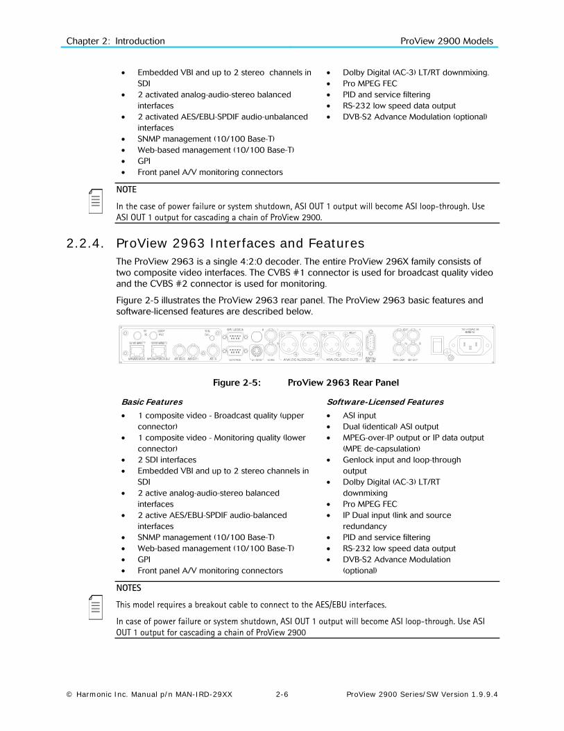
2.2.4. ProView 2963 Interfaces and Features The ProView 2963 is a single 4:2:0 decoder. The entire ProView 296X family consists of two composite video interfaces. The CVBS #1 connector is used for broadcast quality video and the CVBS #2 connector is used for monitoring.
Figure 2-5 illustrates the ProView 2963 rear panel. The ProView 2963 basic features and software-licensed features are described below.
Figure 2-5: ProView 2963 Rear Panel
Basic Features • 1 composite video - Broadcast quality (upper
connector) • 1 composite video - Monitoring quality (lower
connector) • 2 SDI interfaces • Embedded VBI and up to 2 stereo channels in
SDI • 2 active analog-audio-stereo balanced
interfaces • 2 active AES/EBU-SPDIF audio-balanced
interfaces • SNMP management (10/100 Base-T) • Web-based management (10/100 Base-T) • GPI • Front panel A/V monitoring connectors
Software-Licensed Features • ASI input • Dual (identical) ASI output • MPEG-over-IP output or IP data output
(MPE de-capsulation) • Genlock input and loop-through
output • Dolby Digital (AC-3) LT/RT
downmixing • Pro MPEG FEC • IP Dual input (link and source
redundancy • PID and service filtering • RS-232 low speed data output • DVB-S2 Advance Modulation
(optional)
NOTES
This model requires a breakout cable to connect to the AES/EBU interfaces.
In case of power failure or system shutdown, ASI OUT 1 output will become ASI loop-through. Use ASI OUT 1 output for cascading a chain of ProView 2900

Chapter 2: Introduction ProView 2900 Models
© Harmonic Inc. Manual p/n MAN-IRD-29XX 2-7 ProView 2900 Series/SW Version 1.9.9.4
2.2.5. ProView 2980 Interfaces and Features The ProView 2980 is a single 4:2:0/4:2:2 decoder. The ProView 298x family consists of two composite video interfaces. Both CVBS #1 and CVBS #2 connectors are for broadcast quality video. Figure 2-6 illustrates the ProView 2980 rear panel. The ProView 2980 basic and software-licensed features are also detailed.
Figure 2-6: ProView 2980 Rear Panel
Basic Features • 2 composite video interfaces – Broadcast
quality • 2 SDI interfaces • Embedded VBI and up to 4 stereo channels
in SDI • Decoding 4:2:2 PP@ML (1.5–50 Mbps) • 2 out of 4 active analog-audio-stereo
balanced interfaces • 2 out of 4 active AES/EBU-SPDIF audio
unbalanced interfaces • 1ST and 2ND active AES/EBU-SPDIF • SNMP management (10/100 Base-T) • Web-based management (10/100 Base-T) • GPI • Front panel A/V monitoring connectors
Software-Licensed Features • ASI input • Dual (identical) ASI output • MPEG-over-IP output or IP data output (MPE
de-capsulation) • 3RD Active analog stereo pair • 4TH Active analog stereo pair • 3RD Active AES/EBU-SPDIF • 4TH Active AES/EBU-SPDIF • Dolby Digital (AC-3) LT/RT downmixing • Linear PCM (SMPTE 302M 2000), Dolby-E
pass-through • Pro MPEG FEC • IP Dual input (link and source redundancy • PID and service filtering • RS-232 low speed data output • DVB-S2 Advance Modulation (optional)
NOTES
This model requires a breakout cable to connect to the 3rd and 4th analog stereo pairs.
In the case of power failure or system shutdown, ASI OUT 1 output will become ASI loop-through. Use ASI OUT 1 output for cascading a chain of ProView 2900.
Chapter 2: Introduction ProView 2900 Models
© Harmonic Inc. Manual p/n MAN-IRD-29XX 2-8 ProView 2900 Series/SW Version 1.9.9.4
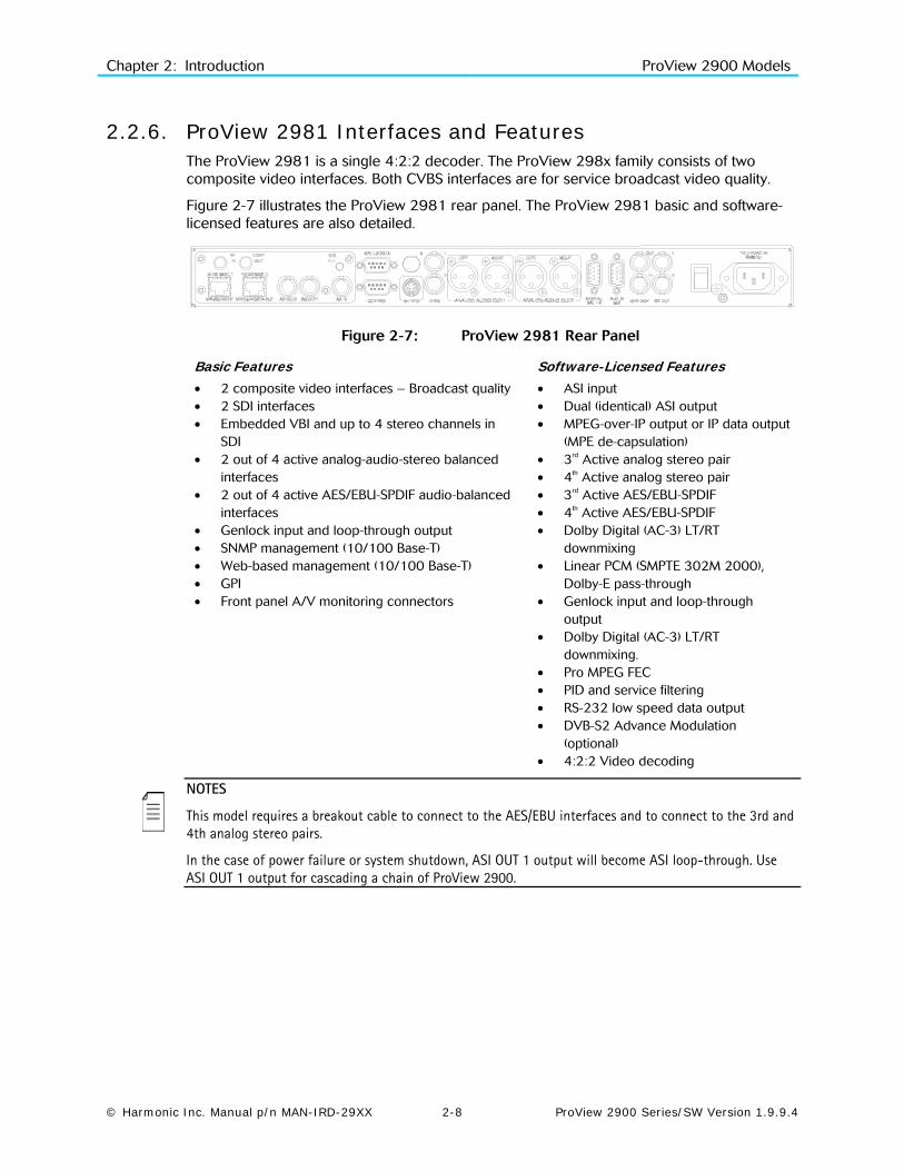
2.2.6. ProView 2981 Interfaces and Features The ProView 2981 is a single 4:2:2 decoder. The ProView 298x family consists of two composite video interfaces. Both CVBS interfaces are for service broadcast video quality.
Figure 2-7 illustrates the ProView 2981 rear panel. The ProView 2981 basic and software-licensed features are also detailed.
Figure 2-7: ProView 2981 Rear Panel
Basic Features • 2 composite video interfaces – Broadcast quality • 2 SDI interfaces • Embedded VBI and up to 4 stereo channels in
SDI • 2 out of 4 active analog-audio-stereo balanced
interfaces • 2 out of 4 active AES/EBU-SPDIF audio-balanced
interfaces • Genlock input and loop-through output • SNMP management (10/100 Base-T) • Web-based management (10/100 Base-T) • GPI • Front panel A/V monitoring connectors
Software-Licensed Features • ASI input • Dual (identical) ASI output • MPEG-over-IP output or IP data output
(MPE de-capsulation) • 3rd Active analog stereo pair • 4th Active analog stereo pair • 3rd Active AES/EBU-SPDIF • 4th Active AES/EBU-SPDIF • Dolby Digital (AC-3) LT/RT
downmixing • Linear PCM (SMPTE 302M 2000),
Dolby-E pass-through • Genlock input and loop-through
output • Dolby Digital (AC-3) LT/RT
downmixing. • Pro MPEG FEC • PID and service filtering • RS-232 low speed data output • DVB-S2 Advance Modulation
(optional) • 4:2:2 Video decoding
NOTES
This model requires a breakout cable to connect to the AES/EBU interfaces and to connect to the 3rd and 4th analog stereo pairs.
In the case of power failure or system shutdown, ASI OUT 1 output will become ASI loop-through. Use ASI OUT 1 output for cascading a chain of ProView 2900.

Chapter 2: Introduction ProView 2900 Models
© Harmonic Inc. Manual p/n MAN-IRD-29XX 2-9 ProView 2900 Series/SW Version 1.9.9.4
2.2.7. ProView 2990 Interfaces and Features The ProView 2990 is a dual 4:2:0 decoder. The ProView 299x family consists of three composite video interfaces. The CVBS #1 connector is for the broadcast quality video of decoder #1. The CVBS #2 is used for monitoring. The CVBS #3 connector is for the broadcast quality video of decoder #2.
Figure 2-8 illustrates the ProView 2990 rear panel. The ProView 2990 basic and software-licensed features are also detailed.
Figure 2-8: ProView 2990 Rear Panel
Basic Features • 1 composite video for program 1- Broadcast
quality (upper-right connector) • 1 composite video for program 2 - Broadcast
quality (upper-left connector) • 1 composite video for program 1- Monitoring
quality (lower connector) • 4 active analog-audio-stereo balanced
interfaces • SNMP management (10/100 Base-T) • Web-based management (10/100 Base-T) • RS-422 high speed data output • GPI
Software Licensed Features • ASI input • Dual (identical) ASI output • Dolby Digital (AC-3) LT/RT
downmixing • RS-232 low speed data output • RS-422 high speed data output • DVB-S2 Advance Modulation
(optional)
NOTE
In the case of power failure or system shutdown, ASI OUT 1 output will become ASI loop-through. Use ASI OUT 1 output for cascading a chain of ProView 2900.
The Russian SECAM D/K (composite video only) is available only through special orders.
Chapter 2: Introduction ProView 2900 Models
© Harmonic Inc. Manual p/n MAN-IRD-29XX 2-10 ProView 2900 Series/SW Version 1.9.9.4
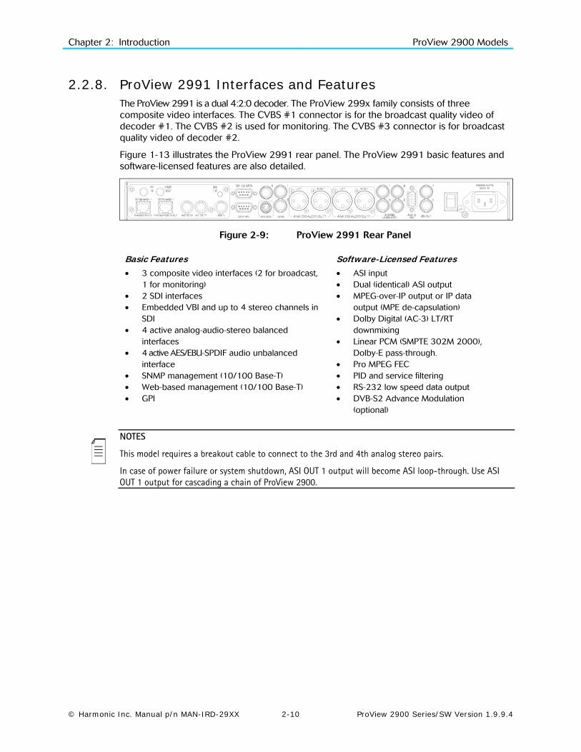
2.2.8. ProView 2991 Interfaces and Features The ProView 2991 is a dual 4:2:0 decoder. The ProView 299x family consists of three composite video interfaces. The CVBS #1 connector is for the broadcast quality video of decoder #1. The CVBS #2 is used for monitoring. The CVBS #3 connector is for broadcast quality video of decoder #2.
Figure 1-13 illustrates the ProView 2991 rear panel. The ProView 2991 basic features and software-licensed features are also detailed.
Figure 2-9: ProView 2991 Rear Panel
Basic Features • 3 composite video interfaces (2 for broadcast,
1 for monitoring) • 2 SDI interfaces • Embedded VBI and up to 4 stereo channels in
SDI • 4 active analog-audio-stereo balanced
interfaces • 4 active AES/EBU-SPDIF audio unbalanced
interface • SNMP management (10/100 Base-T) • Web-based management (10/100 Base-T) • GPI
Software-Licensed Features • ASI input • Dual (identical) ASI output • MPEG-over-IP output or IP data
output (MPE de-capsulation) • Dolby Digital (AC-3) LT/RT
downmixing • Linear PCM (SMPTE 302M 2000),
Dolby-E pass-through. • Pro MPEG FEC • PID and service filtering • RS-232 low speed data output • DVB-S2 Advance Modulation
(optional)
NOTES
This model requires a breakout cable to connect to the 3rd and 4th analog stereo pairs.
In case of power failure or system shutdown, ASI OUT 1 output will become ASI loop-through. Use ASI OUT 1 output for cascading a chain of ProView 2900.
Chapter 2: Introduction ProView 2900 Models
© Harmonic Inc. Manual p/n MAN-IRD-29XX 2-11 ProView 2900 Series/SW Version 1.9.9.4
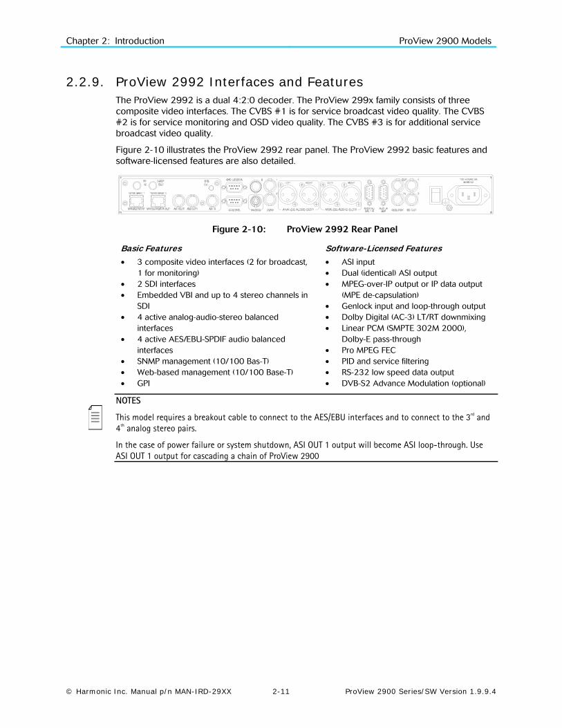
2.2.9. ProView 2992 Interfaces and Features The ProView 2992 is a dual 4:2:0 decoder. The ProView 299x family consists of three composite video interfaces. The CVBS #1 is for service broadcast video quality. The CVBS #2 is for service monitoring and OSD video quality. The CVBS #3 is for additional service broadcast video quality.
Figure 2-10 illustrates the ProView 2992 rear panel. The ProView 2992 basic features and software-licensed features are also detailed.
Figure 2-10: ProView 2992 Rear Panel
Basic Features • 3 composite video interfaces (2 for broadcast,
1 for monitoring) • 2 SDI interfaces • Embedded VBI and up to 4 stereo channels in
SDI • 4 active analog-audio-stereo balanced
interfaces • 4 active AES/EBU-SPDIF audio balanced
interfaces • SNMP management (10/100 Bas-T) • Web-based management (10/100 Base-T) • GPI
Software-Licensed Features • ASI input • Dual (identical) ASI output • MPEG-over-IP output or IP data output
(MPE de-capsulation) • Genlock input and loop-through output • Dolby Digital (AC-3) LT/RT downmixing • Linear PCM (SMPTE 302M 2000),
Dolby-E pass-through • Pro MPEG FEC • PID and service filtering • RS-232 low speed data output • DVB-S2 Advance Modulation (optional)
NOTES
This model requires a breakout cable to connect to the AES/EBU interfaces and to connect to the 3rd and 4th analog stereo pairs.
In the case of power failure or system shutdown, ASI OUT 1 output will become ASI loop-through. Use ASI OUT 1 output for cascading a chain of ProView 2900

Chapter 2: Introduction Mechanical Structure
© Harmonic Inc. Manual p/n MAN-IRD-29XX 2-12 ProView 2900 Series/SW Version 1.9.9.4
2.3. Mechanical Structure The ProView 2900 is housed in a rugged industrial enclosure, 1RU by 19" (rack mount).
Figure 2-11: ProView 2900 Unit – General View
2.3.1. Front Panel The front panel allows control using a four-way touch pad, [Enter] key, [Esc] key, and two programmable [F1]/[F2] keys. Operational commands and parameters are displayed on a graphical LCD. The four-way touch pad allows parameter modification and scrolling through the embedded VBI menus. Two LEDs show the WARNING and PWR/FAIL status (see Figure 2-12).
Figure 2-12: ProView 2900 Front View
2.3.2. Front-Ends ProView 2900 supports the following interfaces:
DVB-S Single L-Band input
DVB-S Dual L-Band input
DVB-DSNG Dual L-Band input
DVB-S2 Dual L-Band input
MPEG over IP (MPEGoIP) dual input
G.703 E3 single input with Loop-through
ASI-In Decoder only (except for ProView 2960)
In this manual all rear panels are displayed with the DVB-S interface. Each model has standard features and interfaces as well as features requiring active software licenses.

Chapter 2: Introduction Mechanical Structure
© Harmonic Inc. Manual p/n MAN-IRD-29XX 2-13 ProView 2900 Series/SW Version 1.9.9.4
The MPEGoIP input interface can be supported by all ProView 2900 devices.
Figure 2-13 illustrates the ProView 2961 rear panel with an MPEGoIP input interface.
Figure 2-14 illustrates the ProView 2961 rear panel with DVB-S (QPSK) Dual Input configuration.
Figure 2-15 displays the ProView 2961 rear panel with Decoder Only configuration.
Figure 2-13: ProView 2961 Rear Panel (IP Input interface)
Figure 2-14: ProView 2961 Rear Panel (DVB-S Dual Input interface)
Figure 2-15: ProView 2961 Rear Panel (Decoder Only interface)
NOTE
ProView 2900 models supporting MPEGoIP output and IP data out (MPE de-capsulation) output can be configured to support either MPEGoIP or IP data out.
Chapter 2: Introduction Characteristics and Specifications
© Harmonic Inc. Manual p/n MAN-IRD-29XX 2-14 ProView 2900 Series/SW Version 1.9.9.4
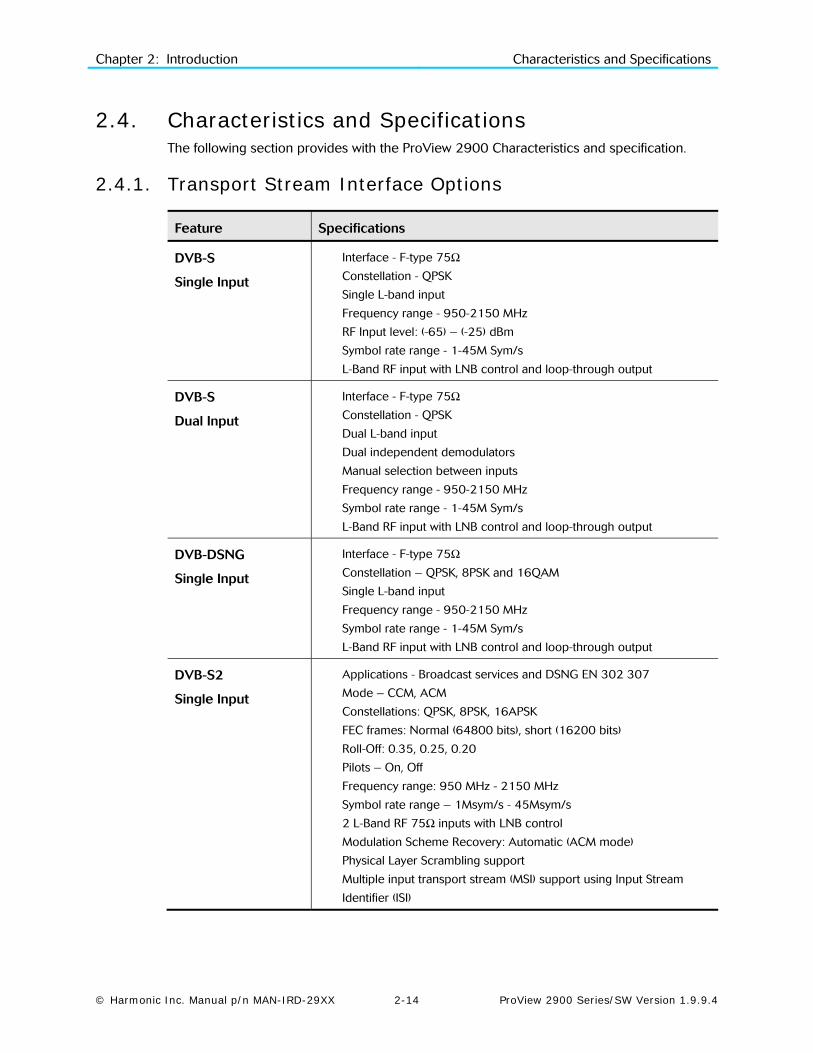
2.4. Characteristics and Specifications The following section provides with the ProView 2900 Characteristics and specification.
2.4.1. Transport Stream Interface Options
Feature Specifications
DVB-S
Single Input
Interface - F-type 75Ω
Constellation - QPSK
Single L-band input
Frequency range - 950-2150 MHz
RF Input level: (-65) – (-25) dBm
Symbol rate range - 1-45M Sym/s
L-Band RF input with LNB control and loop-through output
DVB-S
Dual Input
Interface - F-type 75Ω
Constellation - QPSK
Dual L-band input
Dual independent demodulators
Manual selection between inputs
Frequency range - 950-2150 MHz
Symbol rate range - 1-45M Sym/s
L-Band RF input with LNB control and loop-through output
DVB-DSNG
Single Input
Interface - F-type 75Ω
Constellation – QPSK, 8PSK and 16QAM
Single L-band input
Frequency range - 950-2150 MHz
Symbol rate range - 1-45M Sym/s
L-Band RF input with LNB control and loop-through output
DVB-S2
Single Input
Applications - Broadcast services and DSNG EN 302 307
Mode – CCM, ACM
Constellations: QPSK, 8PSK, 16APSK
FEC frames: Normal (64800 bits), short (16200 bits)
Roll-Off: 0.35, 0.25, 0.20
Pilots – On, Off
Frequency range: 950 MHz - 2150 MHz
Symbol rate range – 1Msym/s - 45Msym/s
2 L-Band RF 75Ω inputs with LNB control
Modulation Scheme Recovery: Automatic (ACM mode)
Physical Layer Scrambling support
Multiple input transport stream (MSI) support using Input Stream
Identifier (ISI)
Chapter 2: Introduction Characteristics and Specifications
© Harmonic Inc. Manual p/n MAN-IRD-29XX 2-15 ProView 2900 Series/SW Version 1.9.9.4
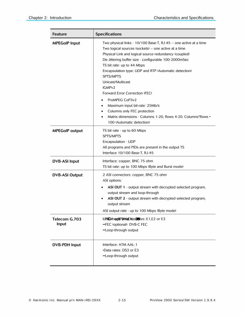
Feature Specifications
MPEGoIP Input Two physical links - 10/100 Base-T, RJ-45 – one active at a time
Two logical sources (sockets) – one active at a time
Physical Link and logical source redundancy (coupled)
De-Jittering buffer size - configurable 100-2000mSec
TS bit rate: up to 44 Mbps
Encapsulation type: UDP and RTP (Automatic detection)
SPTS/MPTS
Unicast/Multicast
IGMPv2
Forward Error Correction (FEC)
• ProMPEG CoP3v2
• Maximum input bit-rate: 25Mb/s
• Columns only FEC protection
• Matrix dimensions - Columns 1-20, Rows 4-20. Columns*Rows •
100 (Automatic detection)
MPEGoIP output TS bit rate - up to 60 Mbps
SPTS/MPTS
Encapsulation - UDP
All programs and PIDs are present in the output TS
Interface 10/100 Base-T, RJ-45
DVB-ASI Input Interface: copper, BNC 75 ohm
TS bit rate: up to 100 Mbps (Byte and Burst mode)
DVB-ASI Output 2 ASI connectors: copper, BNC 75 ohm
ASI options:
• ASI OUT 1 - output stream with decrypted selected program,
output stream and loop-through
• ASI OUT 2 - output stream with decrypted selected program,
output stream
ASI output rate - up to 100 Mbps (Byte mode)
Telecom G.703 Input
Unframed PDH Data rates::E1,E2 or E3
•
• FEC ( opti on al ) : DVB
•
FEC ( opti on al ) : DVB
F
EC ( opti on al ) : DVB
E
C ( opti on al ) : DVB
C
( opti on al ) : DVB
( opti on al ) : DVB
(
opti on al ) : DVB
o
pti on al ) : DVB
p
ti on al ) : DVB
t
i on al ) : DVB
i
on al ) : DVB
o
n al ) : DVB
n
al ) : DVB
a
l ) : DVB
l
) : DVB
)
: DVB
:
DVB
DVB
D
VB
V
B
B-C FEC
••Loop-through output
DVB-PDH Input Interface: ATM AAL-1
•Data rates: DS3 or E3
••Loop-through output
Chapter 2: Introduction Characteristics and Specifications
© Harmonic Inc. Manual p/n MAN-IRD-29XX 2-16 ProView 2900 Series/SW Version 1.9.9.4
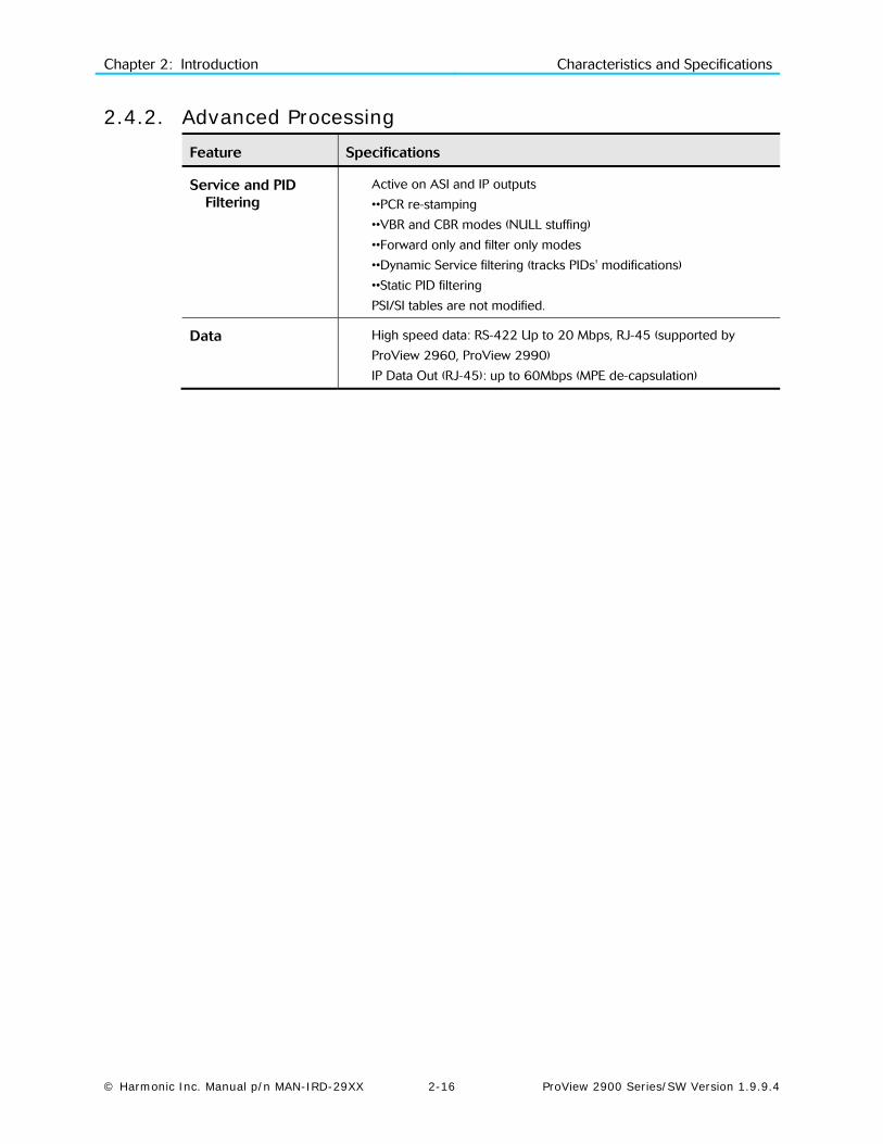
2.4.2. Advanced Processing Feature Specifications
Service and PID Filtering
Active on ASI and IP outputs
••PCR re-stamping
••VBR and CBR modes (NULL stuffing)
••Forward only and filter only modes
••Dynamic Service filtering (tracks PIDs' modifications)
••Static PID filtering
PSI/SI tables are not modified.
Data High speed data: RS-422 Up to 20 Mbps, RJ-45 (supported by
ProView 2960, ProView 2990)
IP Data Out (RJ-45): up to 60Mbps (MPE de-capsulation)

Chapter 2: Introduction Characteristics and Specifications
© Harmonic Inc. Manual p/n MAN-IRD-29XX 2-17 ProView 2900 Series/SW Version 1.9.9.4
2.4.3. Decoder Outputs
Feature Specifications
Video Video Formats:
• PAL-B/G/I/M/N/D, NTSC, SECAM L/B/G/K1
• Russian SECAM D/K (composite video only supported only by
special order in ProView 2960, ProView 2961 and
ProView 2990)
Decoding:
• 4:2:0 MP@ML (1.5 – 15 Mbps)
• 4:2:2 PP@ML (1.5 – 50 Mbps) (supported only in ProView 298x)
Maximum TS decoding bit rate: 108Mbps
Video resolution interpolation: Pan-scan, letter box or Pass through
Aspect ratios: 4:3/16:9
Aspect ratio 14:9 by signaling over VBI video index
Graphical processing (OSD): DVB subtitling, EBU (Teletext) subtitling
OSD only through monitoring output
Genlock input and loop-through output and phase compensation
(supported only by ProView 2962, ProView 2963, ProView 2981
and ProView 2992)
Genlock Sync lock resolution: +/- 37nSec
Front panel Monitoring
Video monitor output connector (Supported only by 298x)
Audio monitor output connector (Supported only by 298x)
VBI Re-insertion All VBIs adhere the relevant standards including the line numbers
In composite video and embedded SDI
WST Teletext and inverted Teletext
WSS, VPS, VITC, CC, AMOL I, AMOL II (Nielsen), TV-Guide, V-CHIP
Enhanced VITS with built-in generator
Audio Modes: stereo, joint stereo, dual channel, single channel
Analog max output level: +18 dBu @ 600Ω
Digital max output level: 0 dBFs
Attenuation control at -64 dB to 0 dB and mute
Dolby Digital (AC-3) Pass-through
Dolby Digital (AC-3) LT/RT downmixing
Linear PCM (SMPTE 302M 2000) supported over analog and digital
outputs 2/3/4 (supported in ProView 2980, ProView 2981,
ProView 2991, ProView 2992)
Dolby-E pass-through supported over digital outputs 2/3/4
(supported in ProView 2980, ProView 2981, ProView 2991,
ProView 2992)

Chapter 2: Introduction Characteristics and Specifications
© Harmonic Inc. Manual p/n MAN-IRD-29XX 2-18 ProView 2900 Series/SW Version 1.9.9.4
2.4.4. Conditional Access
Feature Specifications
Embedded DVB-Descrambling
BISS mode-1
BISS-E
CAS-5000
DVB-CI Interface – 2 CI slots EN-50221 (Only 1 active simultaneously)
Maximum of decrypted programs - 1 for single decoder, and 2 for
dual decoder (in case the specific CAM supports it).
Maximum TS bitrate – 72 Mbps
CA methods: Multicrypt, Simulcrypt
CASs: Viaccess®, Irdeto®, Conax®, MediaGuard®, Nagravision®,
Cryptoworks®, VideoGuard®, OnDigital®, CODICrypt®

Chapter 2: Introduction Characteristics and Specifications
© Harmonic Inc. Manual p/n MAN-IRD-29XX 2-19 ProView 2900 Series/SW Version 1.9.9.4
2.4.5. Control and Monitoring
Feature Specifications
Local Graphical easy-to-use front panel
Advanced satellite scanning (CLI support only)
Operates in service and PID modes
2 GPI dry contacts for various status and fault indications
Enhanced DVB Monitoring
Front panel display: signal quality, Eb/N0, BER, ASI format, network
and service information, CA information, CI slots, video and audio
decoded information
Remote SNMP management
Web-based management
Telnet
Terminal via RS-232 or RS-485
Software download
Over the Air Software download
2.4.6. Compliance
Feature Specifications
EMC EN55013 (CISPR 13)
EN55020 (CISPR 20)
EN55022 (CISPR 22)
EN55024 (CISPR 24)
FCC part 15 (Class B)
Safety EN60950
CB (IEC60950)
UL60950
cTUVus
Chapter 2: Introduction Characteristics and Specifications
© Harmonic Inc. Manual p/n MAN-IRD-29XX 2-20 ProView 2900 Series/SW Version 1.9.9.4
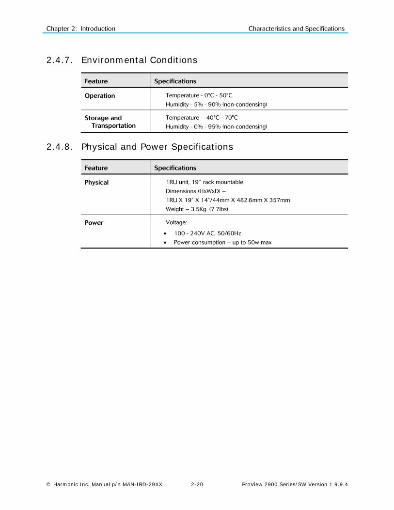
2.4.7. Environmental Conditions
Feature Specifications
Operation Temperature - 0°C - 50°C
Humidity - 5% - 90% (non-condensing)
Storage and Transportation
Temperature - -40°C - 70°C
Humidity - 0% - 95% (non-condensing)
2.4.8. Physical and Power Specifications
Feature Specifications
Physical 1RU unit, 19’’ rack mountable
Dimensions (HxWxD) –
1RU X 19” X 14”/44mm X 482.6mm X 357mm
Weight – 3.5Kg. (7.7lbs).
Power Voltage:
• 100 - 240V AC, 50/60Hz
• Power consumption – up to 50w max

© Harmonic Inc. Manual p/n MAN-IRD-29XX 3-1 ProView 2900 Series/SW Version 1.9.9.4
Chapter 3 Installation
This section details the safety precautions and inventory check when installing the Harmonic ProView 2900 Series. It also details the initialization and basic configuration instructions for a newly installed ProView 2900..
3.1. Safety Precautions To avoid injury and prevent equipment damage, observe the following safety precautions:
• Do not move or ship equipment unless it is correctly packaged in its original wrapping and shipping containers.
• Only Harmonic trained personnel can perform service and maintenance.
• To prevent lightning damage, ground the unit according to local regulations.
• Do not permit unqualified personnel to operate the unit.
3.1.1. Restricted Access Area The DC powered equipment should only be installed in a Restricted Access Area.
3.1.2. Installation Codes This device must be installed according to national electrical codes. For North America, equipment must be installed in accordance with the US National Electrical Code, Articles 110-16, 110-17, and 110-18 and the Canadian Electrical Code, Section 12.
Add Markings for AC units for Denmark, Finland, and Sweden (marked on product):
• Denmark- “Unit is class I, unit shall be used with an AC cord set suitable with Denmark deviations. Cord shall including an earthing conductor. Unit shall be plugged into a wall socket outlet which connected to protective earth. Socket outlets which are not connected to earth shall not be used!”
• Finland - (Marking label and in manual) -"Laite on liitettävä suojamaadoituskoskettimilla varustettuun pistorasiaan”
• Sweden (Marking label and in manual) - "Apparaten skall anslutas till jordat uttag."
For North American
Power connection, select a power supply cord that is UL Listed and CSA Certified 3 - conductor, [18 AWG], terminated in a molded on plug cap rated 125 V, [15 A], with a minimum length of 1.5m [six feet] but no longer than 4.5m...For European connection, select a power supply cord that is internationally harmonized and marked "<HAR>", 3 - conductor, 0,75 mm2 minimum mm2 wire, rated 300 V, with a PVC insulated jacket. The cord must have a molded on plug cap rated 250 V, 10 A...".
Chapter 3: ProView 2900 Control Interfaces Installation Instructions
© Harmonic Inc. Manual p/n MAN-IRD-29XX 3-2 ProView 2900 Series/SW Version 1.9.9.4
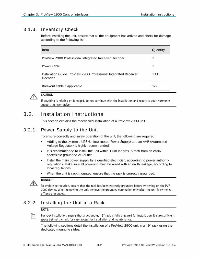
3.1.3. Inventory Check Before installing the unit, ensure that all the equipment has arrived and check for damage according to the following list:
Item Quantity
ProView 2900 Professional Integrated Receiver Decoder 1
Power cable 1
Installation Guide, ProView 2900 Professional Integrated Receiver Decoder
1 CD
Breakout cable if applicable 1/2
CAUTION
If anything is missing or damaged, do not continue with the installation and report to your Harmonic support representative.
3.2. Installation Instructions This section explains the mechanical installation of a ProView 2900 unit.
3.2.1. Power Supply to the Unit To ensure correctly and safely operation of the unit, the following are required:
• Adding to the system a UPS (Uninterrupted Power Supply) and an AVR (Automated Voltage Regulator) is highly recommended.
• It is recommended to install the unit within 1.5m (approx. 5 feet) from an easily accessible grounded AC outlet.
• Install the main power supply by a qualified electrician, according to power authority regulations. Make sure all powering must be wired with an earth leakage, according to local regulations.
• When the unit is rack-mounted, ensure that the rack is correctly grounded.
DANGER:
To avoid electrocution, ensure that the rack has been correctly grounded before switching on the PVR-7000 device. When removing the unit, remove the grounded connection only after the unit is switched off and unplugged.
3.2.2. Installing the Unit in a Rack NOTE:
For rack installation, ensure that a designated 19" rack is fully prepared for installation. Ensure sufficient space behind the rack for easy access for installation and maintenance.
The following sections detail the installation of a ProView 2900 unit in a 19" rack using the dedicated mounting slides.
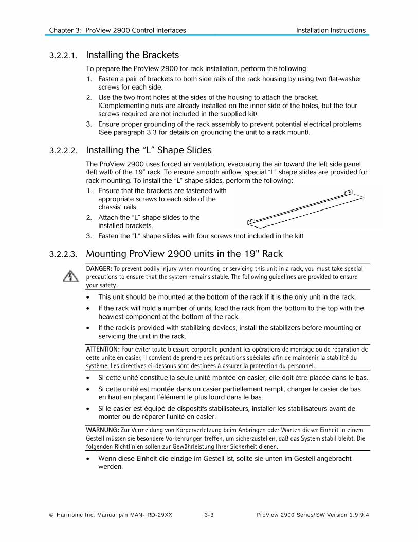
Chapter 3: ProView 2900 Control Interfaces Installation Instructions
© Harmonic Inc. Manual p/n MAN-IRD-29XX 3-3 ProView 2900 Series/SW Version 1.9.9.4
3.2.2.1. Installing the Brackets To prepare the ProView 2900 for rack installation, perform the following:
1. Fasten a pair of brackets to both side rails of the rack housing by using two flat-washer screws for each side.
2. Use the two front holes at the sides of the housing to attach the bracket. (Complementing nuts are already installed on the inner side of the holes, but the four screws required are not included in the supplied kit).
3. Ensure proper grounding of the rack assembly to prevent potential electrical problems (See paragraph 3.3 for details on grounding the unit to a rack mount).
3.2.2.2. Installing the “L” Shape Slides The ProView 2900 uses forced air ventilation, evacuating the air toward the left side panel (left wall) of the 19” rack. To ensure smooth airflow, special “L” shape slides are provided for rack mounting. To install the “L” shape slides, perform the following:
1. Ensure that the brackets are fastened with appropriate screws to each side of the chassis’ rails.
2. Attach the “L” shape slides to the installed brackets.
3. Fasten the “L” shape slides with four screws (not included in the kit)
3.2.2.3. Mounting ProView 2900 units in the 19" Rack DANGER: To prevent bodily injury when mounting or servicing this unit in a rack, you must take special precautions to ensure that the system remains stable. The following guidelines are provided to ensure your safety.
• This unit should be mounted at the bottom of the rack if it is the only unit in the rack.
• If the rack will hold a number of units, load the rack from the bottom to the top with the heaviest component at the bottom of the rack.
• If the rack is provided with stabilizing devices, install the stabilizers before mounting or servicing the unit in the rack.
ATTENTION: Pour éviter toute blessure corporelle pendant les opérations de montage ou de réparation de cette unité en casier, il convient de prendre des précautions spéciales afin de maintenir la stabilité du système. Les directives ci-dessous sont destinées à assurer la protection du personnel.
• Si cette unité constitue la seule unité montée en casier, elle doit être placée dans le bas.
• Si cette unité est montée dans un casier partiellement rempli, charger le casier de bas en haut en plaçant l’élément le plus lourd dans le bas.
• Si le casier est équipé de dispositifs stabilisateurs, installer les stabilisateurs avant de monter ou de réparer l'unité en casier.
WARNUNG: Zur Vermeidung von Körperverletzung beim Anbringen oder Warten dieser Einheit in einem Gestell müssen sie besondere Vorkehrungen treffen, um sicherzustellen, daß das System stabil bleibt. Die folgenden Richtlinien sollen zur Gewährleistung Ihrer Sicherheit dienen.
• Wenn diese Einheit die einzige im Gestell ist, sollte sie unten im Gestell angebracht werden.

Chapter 3: ProView 2900 Control Interfaces Installation Instructions
© Harmonic Inc. Manual p/n MAN-IRD-29XX 3-4 ProView 2900 Series/SW Version 1.9.9.4
• Bei Anbringung dieser Einheit in einem zum Teil gefüllten Gestell ist das Gestell von unten nach oben zu laden, wobei das schwerste Bauteil unten im Gestell anzubringen ist.
• Wird das Gestell mit Stabilisierungszubehör geliefert, sind zuerst die Stabilisatoren zu installieren, bevor sie die Einheit im Gestell anbringen oder sie warten.
To mount the 19”/42U rack with the ProView 2900 units perform the following:
1. Verify using of appropriate brackets and L” shape slides according to 3.2.2.1 and 3.2.2.2.sections.
2. Mount the ProView 2900 in groups of five units (maximum) upon each pair of brackets.
3. Leave ‘one-unit-space’ between each group of five units.
NOTE: The maximum number of ProView 2900s per a 19”/42U rack is 35 (seven groups of five units).
CAUTION: Ensure that a sufficient amount of airflow enters the ProView 2900 from the left end (from the front panel point of view)
Consider if other devices in the rack use airflow in the opposite direction.
3.2.3. Insertion of the DVB-CI Module (PCMCIA) Caution
Do not remove or insert the DVB-CI module or the Smart Card while the ProView 2900 is powering up or initializing.
Figure 3-1: DVB-CI Module
Figure 3-1 illustrates the ProView 2900 with the DVB-CI module (PCMCIA card) and the Smart Card used to decrypt the incoming signal. The ProView 2900 is provided with two PCMCIA slots for up to two DVB-CI modules. The PCMCIA should be firmly inserted into one of the two provided slots to ensure contact. Each DVB-CI module accommodates one Smart Card, inserted with the UP mark pointing upwards and forward.
When installed, the card is detected automatically by the ProView 2900 and enabled if the three following conditions are valid:
• The installed card must be EN50221 compatible • Services have been selected at TV1/TV2 (for
further information see section 8.2) • Using a valid card licensing

Chapter 3: ProView 2900 Control Interfaces Electrical Installation
© Harmonic Inc. Manual p/n MAN-IRD-29XX 3-5 ProView 2900 Series/SW Version 1.9.9.4
3.3. Electrical Installation DANGER: Do not connect power to the unit until you have verified that the line voltage is correct and the correct fuses are installed. Failure to do so may result in electrical shock. If the unit is rack mounted, ensure that the unit is grounded to the rack and the rack is correctly grounded.
CAUTION: This product relies on the building’s electrical installation for short-circuit (overcurrent) protection. Ensure that a fuse or circuit breaker no larger than 120 VAC, 20 A U.S. (240 VAC, 20 A international) is used on the phase conductors (all current-carrying conductors).
ATTENTION: Pour ce qui est de la protection contre les courts-circuits (surtension), ce produit dépend de l’installation électrique du local. Vérifier qu’un fusible ou qu’un disjoncteur de 120 V alt., 20 A U.S. maximum (240 V alt., 20 A international) est utilisé sur les conducteurs de phase (conducteurs de charge).
WARNUNG: Dieses Produkt ist darauf angewiesen, daß im Gebäude ein Kurzschluß-bzw. Überstromschutz installiert ist. Stellen sie sicher, daß eine Sicherung oder ein Unterbrecher von nicht mehr als 240 V Wechselstrom, 20 A (bzw. in den USA 120 V Wechselstrom, 20 A) an den Phasenleitern (allen stromführenden Leitern) verwendet wird.
3.3.1. Cable Connection The ProView 2900 provides all the connections on its rear panel. The rear panel is comprised of audio outputs, video outputs, data outputs, and control interfaces.
Figure 3-2 illustrates the ProView 2992 rear panel in order show connector types and Table 3-1 describes the various connectors and cables required to connect the unit.
Figure 3-2: ProView 2992 Rear Panel
Table 3-1: ProView 2900 Rear Panel – Connectors and Cables
Interface Connector Type Cable Type
L-Band Front-end RF IN 75 Ω F-Type RG-6
L-Band Front-end Loop-Through Connector
75 Ω F-Type RG-6
MPEGoIP Input RJ-45 FTP Cat 5
Management RJ-45 FTP Cat 5
MPEGoIP/DATA Output RJ-45 FTP Cat 5
Analog Audio Out1 left 600 Ω XLR (balanced) Shielded audio cable

Chapter 3: ProView 2900 Control Interfaces Electrical Installation
© Harmonic Inc. Manual p/n MAN-IRD-29XX 3-6 ProView 2900 Series/SW Version 1.9.9.4
Table 3-1: ProView 2900 Rear Panel – Connectors and Cables
Interface Connector Type Cable Type
Analog Audio Out1 right 600 Ω XLR (balanced) Shielded audio cable
Analog Audio Out2 left 600 Ω XLR (balanced) Shielded audio cable
Analog Audio Out2 right 600 Ω XLR (balanced) Shielded audio cable
Video Out, S-Video Y/C 75 Ω DIN connector Super video cable
Composite Video Out, CVBS1
75 Ω BNC RG-59 RG11 A/U (recommended)
Composite Video Out, CVBS2
75 Ω BNC RG-59 RG11 A/U (recommended)
Composite Video Out, CVBS3
75 Ω BNC RG-59 RG11 A/U (recommended)
Data Output (RS-232/RS-422)
9 PIN D-Type Serial Cable
Control (RS-232/RS-485) 9 PIN D-Type Serial Cable
Audio Balanced 3 & 4 600 Ω D-sub 15p to 4XLR
Breakout Cable 204346 (Harmonic material)
AES/EBU 1-4 Unbalanced 75 Ω 4xBNC or 75 Ω D-sub 15p
BNC Cable
ASI in/out1/out2 75 Ω BNC RG-59 RG11 A/U (recommended)
Genlock In 75 Ω BNC RG-59 RG11 A/U (recommended)
Genlock Out 75 Ω BNC RG-59 RG11 A/U (recommended)
SDI out 1 &2 75 Ω BNC RG-59
The ProView 2900 series supports terminal-control from a standard PC through a serial RS-232 / RS-485 connector.
Figure 3-3 illustrates the Control Interface and Low Speed Data/GPI 9-pin male connectors pin numbering. Table 3-2 lists the RS-232/RS-485 Control Interface connector pin-out. Table 3-3 lists the RS-232 low speed data and GPI interface pin-out. This connector is used at the same time for both GPI and low-speed data output. Table 3-4 lists the RS-422 high speed data and interface pin-out.
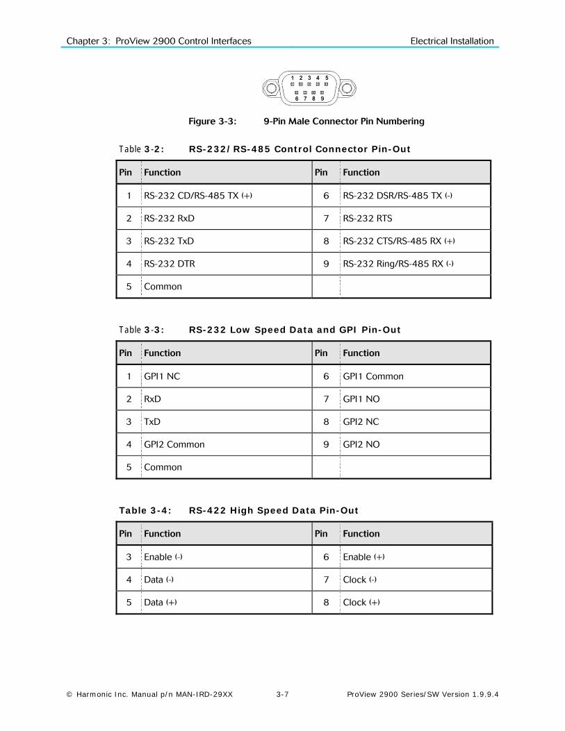
Chapter 3: ProView 2900 Control Interfaces Electrical Installation
© Harmonic Inc. Manual p/n MAN-IRD-29XX 3-7 ProView 2900 Series/SW Version 1.9.9.4
Figure 3-3: 9-Pin Male Connector Pin Numbering
Table 3-2: RS-232/RS-485 Control Connector Pin-Out
Pin Function Pin Function
1 RS-232 CD/RS-485 TX (+) 6 RS-232 DSR/RS-485 TX (-)
2 RS-232 RxD 7 RS-232 RTS
3 RS-232 TxD 8 RS-232 CTS/RS-485 RX (+)
4 RS-232 DTR 9 RS-232 Ring/RS-485 RX (-)
5 Common
Table 3-3: RS-232 Low Speed Data and GPI Pin-Out
Pin Function Pin Function
1 GPI1 NC 6 GPI1 Common
2 RxD 7 GPI1 NO
3 TxD 8 GPI2 NC
4 GPI2 Common 9 GPI2 NO
5 Common
Table 3-4: RS-422 High Speed Data Pin-Out
Pin Function Pin Function
3 Enable (-) 6 Enable (+)
4 Data (-) 7 Clock (-)
5 Data (+) 8 Clock (+)

Chapter 3: ProView 2900 Control Interfaces Electrical Installation
© Harmonic Inc. Manual p/n MAN-IRD-29XX 3-8 ProView 2900 Series/SW Version 1.9.9.4
Table 3-5 lists the Audio 3-4 breakout cable interface pin-out.
Table 3-5: Audio 3-4 Breakout Cable Pin-Out (Harmonic P/N 204346)
Pin Function Pin Function
1 Audio 4 XLR Right (+) 8 Audio 4 XLR Left Common
2 Audio 4 XLR Left (+) 10 Audio 3 XLR Left Common
3 Audio 3 XLR Right Common 11 Audio 4 XLR Right (-)
4 Audio 3 XLR Right (+) 12 Audio 4 XLR Left (-)
5 Audio 3 XLR Left (+) 14 Audio 3 XLR Right (-)
7 Audio 4 XLR Right Common 15 Audio 3 XLR Left (-)
Table 3-6 lists the AES/ABU balanced breakout cable pin-out.
Table 3-6: AES/EBU Balanced Breakout Cable Pin-Out (Harmonic P/N 204345)
Pin Function Pin Function
1 AES/EBU 4 (+) 8 AES/EBU 3 Common
2 AES/EBU 3 (+) 10 AES/EBU 1 Common
3 AES/EBU 2 Common 11 AES/EBU 4 (-)
4 AES/EBU 2 (+) 12 AES/EBU 3 (-)
AES/EBU 1 (+) 14 AES/EBU 2 (-)
7 AES/EBU 4 Common 15 AES/EBU 1 (-)
3.3.2. Electrical Power Connection The ProView 2900 is powered by an AC power supply unit or by an optional external DC power source. The following describes the AC and CD electrical power connections.
DANGER: Do not connect power to the unit until you have verified that the line voltage is correct and the correct fuses are installed. Failure to do so may result in electrical shock. If the unit is rack mounted, ensure that the unit is grounded to the rack and the rack is correctly grounded.
A rack-mounted ProView 2900 Grounding jackscrew must be connected to the rack housing, which must be correctly grounded (see Figure 3-4 and Figure 3-5).

Chapter 3: ProView 2900 Control Interfaces Electrical Installation
© Harmonic Inc. Manual p/n MAN-IRD-29XX 3-9 ProView 2900 Series/SW Version 1.9.9.4
3.3.2.1. AC Power Supply Grounding of the ProView 2900 is provided when the AC power cable is connected to the device’s AC connector. The ProView 2900 is shipped with either one of the AC connector configuration, as shown in Figure 3-4.
AC Power Supply Configuration 1 AC Power Supply Configuration 2
Figure 3-4: AC Power Supply and Rack-Mount Grounding Jackscrew
3.3.2.2. DC Power Supply DC power supply is an optional feature of the ProView 2900.
If the unit is fitted with a -48V CD power supply, connect the external 48V DC source by performing the following (refer to Figure 3-5):
1. Connect a (+) 48V DC source wire to the (+) contact on the power terminal board.
2. Connect a (-) 48V DC source wire to the (-) contact on the power terminal board.
3. Connect Grounding point wire to the (GND) contact on the power terminal board.
When the ProView 2900 is rack-mounted, the Grounding jackscrew (see Figure 3-5) must be connected to the rack housing, which in turn should be properly grounded.
Figure 3-5: DC Power Supply and Rack-Mount Grounding Jackscrew
Chapter 3: ProView 2900 Control Interfaces Initialization and Configuration
© Harmonic Inc. Manual p/n MAN-IRD-29XX 3-10 ProView 2900 Series/SW Version 1.9.9.4
3.4. Initialization and Configuration Before powering-up the ProView 2900, ensure that all cabling is correctly connected. Ensure that the unit is connected to the main power supply and correctly grounded.
3.4.1. Powering Up When powering up the ProView 2900 and the receiver is not tuned, expect one of the following warnings:
• Front-End warning – Demodulator not sync
• Bit Stream warning – No sync – 0x47 detected
• Bit Stream warning – PSI not detected
In case the ProView 2900 warning LED is lit orange, the operator must perform the following:
• Tune or configure the ProView 2900 device
• Select a service from the input stream
When the ProView 2900 is correctly configured, “All OK” is displayed and both LEDs are lit green.
NOTE
Prior to initialization, review Chapter 5-Operation and Management, for how to use and navigate through the menus and for information on configuration parameters.
3.4.2. Tuning The ProView 2900 receiver must be configured to receive a transport stream. For details about a ProView 2900 device with a DVB-S receiver module, see Section 6.2. For details about a ProView 2900 device with an MPEG-over-IP front-end module, see Section 6.2.3.10.
3.4.3. Serviceability Check After installing, initializing, or configuring the ProView 2900, maintenance checks must be performed to ensure that the unit is serviceable. A video monitor must be connected to the ProView 2900 to perform the check lists systematic instructions for performing a serviceability check.
1 On the LCD display, the LCD status message reads "STATUS OK".
2 On the ProView 2900 front panel the two LEDs are lit green.
3 The service selected is displayed on the LCD display.
4 Video picture is displayed on monitor.
5 Audio channels left and right.

© Harmonic Inc. Manual p/n MAN-IRD-29XX 4-1 ProView 2900 Series/SW Version 1.9.9.4
Chapter 4 ProView 2900 Control Interfaces
This section explains the ProView 2900 Front Panel and Web Management control interfaces used for operating, configuring, and monitoring the ProView 2900 operation.
4.1. Front Panel Control Interface
4.1.1. Controls and Displays The front panel is used for extensive local control and for monitoring the device’s operation. Figure 4-1 illustrates the ProView 2900 front panel.
Figure 4-1: Front Panel
The ProView 2900 front panel contains:
• LCD Display The LCD display is a large, easy to use, graphical display. It is used to display enhanced menus with graphical interfaces, such as: charts, radio buttons, tables, and icons.
• Status LEDs The two LEDs indicate WARNING and PWR/FAIL statuses. When both LEDs are lit green the ProView 2900 status is OK. The WARNING LED (Green/Orange) indicates the operational status. The PWR/FAIL LED (Green/Red) indicates the hardware status.
• Arrow Keys The arrow keys include [Up], [Down], [Right], [Left]. The keys are used to navigate between the different menu items and sub-menus. They are also used to select and change parameters during setup and configuration procedures.
• [Enter] Key The Enter key is used for selecting or entering a configuration setup.
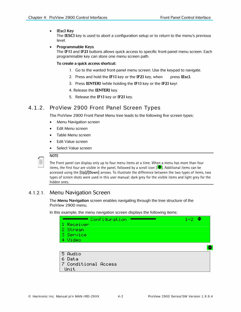
Chapter 4: ProView 2900 Control Interfaces Front Panel Control Interface
© Harmonic Inc. Manual p/n MAN-IRD-29XX 4-2 ProView 2900 Series/SW Version 1.9.9.4
• [Esc] Key The [ESC] key is used to abort a configuration setup or to return to the menu's previous level.
• Programmable Keys The [F1] and [F2] buttons allows quick access to specific front-panel menu screen. Each programmable key can store one menu screen path.
To create a quick access shortcut:
1. Go to the wanted front-panel menu screen. Use the keypad to navigate.
2. Press and hold the [F1] key or the [F2] key, when press [Esc].
3. Press [ENTER] (while holding the [F1] key or the [F2] key).
4. Release the [ENTER] key.
5. Release the [F1] key or [F2] key.
4.1.2. ProView 2900 Front Panel Screen Types The ProView 2900 Front Panel Menu tree leads to the following five screen types:
• Menu Navigation screen
• Edit Menu screen
• Table Menu screen
• Edit Value screen
• Select Value screen
NOTE
The Front panel can display only up to four menu items at a time. When a menu has more than four items, the first four are visible in the panel, followed by a scroll icon [ ]. Additional items can be accessed using the [Up]/[Down] arrows. To illustrate the difference between the two types of items, two types of screen shots were used in this user manual: dark grey for the visible items and light grey for the hidden ones.
4.1.2.1. Menu Navigation Screen The Menu Navigation screen enables navigating through the tree structure of the ProView 2900 menu.
In this example, the menu navigation screen displays the following items:
Configuration 1-2
1 Receiver
2 Stream
3 Service
4 Video
5 Audio
6 Data
7 Conditional Access
Unit
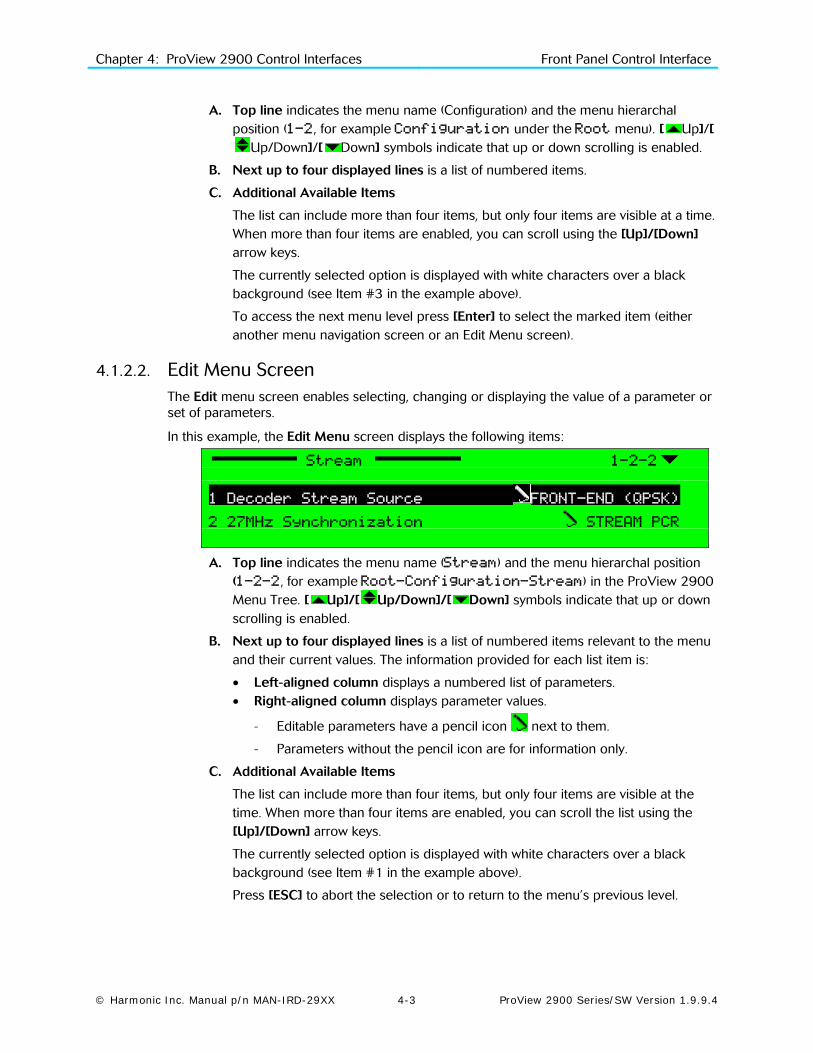
Chapter 4: ProView 2900 Control Interfaces Front Panel Control Interface
© Harmonic Inc. Manual p/n MAN-IRD-29XX 4-3 ProView 2900 Series/SW Version 1.9.9.4
A. Top line indicates the menu name (Configuration) and the menu hierarchal position (1-2, for example Configuration under the Root menu). [ Up]/[
Up/Down]/[ Down] symbols indicate that up or down scrolling is enabled.
B. Next up to four displayed lines is a list of numbered items.
C. Additional Available Items
The list can include more than four items, but only four items are visible at a time. When more than four items are enabled, you can scroll using the [Up]/[Down] arrow keys.
The currently selected option is displayed with white characters over a black background (see Item #3 in the example above).
To access the next menu level press [Enter] to select the marked item (either another menu navigation screen or an Edit Menu screen).
4.1.2.2. Edit Menu Screen The Edit menu screen enables selecting, changing or displaying the value of a parameter or set of parameters.
In this example, the Edit Menu screen displays the following items:
Stream 1-2-2
1 Decoder Stream Source FRONT-END (QPSK)
2 27MHz Synchronization STREAM PCR
A. Top line indicates the menu name (Stream) and the menu hierarchal position (1-2-2, for example Root-Configuration-Stream) in the ProView 2900 Menu Tree. [ Up]/[ Up/Down]/[ Down] symbols indicate that up or down scrolling is enabled.
B. Next up to four displayed lines is a list of numbered items relevant to the menu and their current values. The information provided for each list item is:
• Left-aligned column displays a numbered list of parameters. • Right-aligned column displays parameter values.
- Editable parameters have a pencil icon next to them.
- Parameters without the pencil icon are for information only.
C. Additional Available Items
The list can include more than four items, but only four items are visible at the time. When more than four items are enabled, you can scroll the list using the [Up]/[Down] arrow keys.
The currently selected option is displayed with white characters over a black background (see Item #1 in the example above).
Press [ESC] to abort the selection or to return to the menu’s previous level.

Chapter 4: ProView 2900 Control Interfaces Front Panel Control Interface
© Harmonic Inc. Manual p/n MAN-IRD-29XX 4-4 ProView 2900 Series/SW Version 1.9.9.4
Press [Enter] to select the pointed editable option; a parameter-editing screen is displayed. This can be a Table Menu screen, an Edit Value screen, or a Select Value screen.
4.1.2.3. Table Menu Screen The Table menu screen displays parameter information, using a table format.
In this example, the Table Menu screen displays the following columns:
Name ID Type Mode
1 PROGRAM 1 000A TV FTA
2 PROGRAM 2 0046 TV FTA
3 PROGRAM 3 0050 TV CAS
4 PROGRAM 4 01F7 TV CAS
A. Top line displays the headers for each table column.
B. Next up to four displayed lines is a numbered list of parameters relevant to the menu and their current values. A radio button indicates which parameter is currently active ( is currently enabled and is currently disabled)
C. Additional Available Items
The list can include more than four items, but only four items are visible at a time. When more than four items are available, you can scroll the list using the [Up]/[Down] arrow keys.
The currently selected option is displayed with white characters over a black background (see Item #2 in the example above).
Press [ESC] to abort the selection and return to the Edit Menu screen without changing the parameters.
Press [Enter] to select the currently enabled button . The selected option becomes enabled and the former active option is disabled.
4.1.2.4. Edit Value Screen The Edit Value screen enables setting a parameter value. The parameter value can be a number or a string of characters. Each digit or character is set up individually.
In this example, the Edit Value screen displays the following information:
Pcr1
1062 [Hex]
<0000 – 1FFF>
A. Top line displays the parameter name (Pcr1). The pencil icon indicates that the parameter value is editable.
B. Second line displays the current parameter value. Change the value of the parameter with the arrow keys:

Chapter 4: ProView 2900 Control Interfaces Front Panel Control Interface
© Harmonic Inc. Manual p/n MAN-IRD-29XX 4-5 ProView 2900 Series/SW Version 1.9.9.4
• [Left] and [Right] arrow keys are used to mark a digit or a character for change. The marked digit or a character is displayed with white character over black background (see example in page 3-5)
• [Up] and [Down] arrow keys are used to scroll up or down the digits (0 through 9) or the characters (a to z, A to Z, 0 to 9 and so on.). The scroll range can be limited to prevent values being out of range.
C. Third line displays the allowed range of parameter values.
Press [ESC] to abort the setup and return one level up to the Edit Value Screen without changing the parameters.
Press [Enter] to accept the value. The display returns one level up to the Edit Value Screen and the new value is displayed as the current parameter value.
NOTE
When entering a wrong or out-of-range value, the display dismisses the last change and returns one level up in the menu tree.
4.1.2.5. Select Value Screen (Multiple Choices) The Select Value screen displays a list of selectable items.
In this example, the Select Value screen displays the following information:
Format
3 PAL M
4 PAL BG
5 PAL D
6 PAL N
A. Top line displays the parameter name (Format). The pencil icon indicates that the items are selectable from the list of displayed options. [ Up]/[ Up/Down]/[ Down] symbols indicate that up or down scrolling is enabled.
B. Next up to four displayed lines is a numbered list of parameters relevant to the menu and their current values. A radio button indicates which parameters are currently activated ( is currently enabled and is currently disabled)
C. Additional Available Items
The list can include more than four items, but only four items are visible at a time. When more than four items exist, you can scroll the list using the [Up]/[Down] arrow keys.
The currently selected option is displayed with white characters over a black background (see Item #4 in the example above).
Press [ESC] to abort setup and return one level up to the Select Value Screen without changing the parameters.
Press [Enter] to select the marked option (the selected option is enabled and the former enabled option is disabled ). The display returns up one level to the Select Value screen; the new option is displayed as the current parameter option.

Chapter 4: ProView 2900 Control Interfaces Front Panel Control Interface
© Harmonic Inc. Manual p/n MAN-IRD-29XX 4-6 ProView 2900 Series/SW Version 1.9.9.4
4.1.3. Front Panel Initialization Sequence To activate the ProView 2900 Front Panel Root Menu perform the following:
1. Power up the ProView 2900. The ProView 2900 initialization phase begins and the initialization message is displayed.
MPEG-2 I.R. Service1:
Initializing
Please Wait...
2. When initialization complete, the ProView 2900 displays one of two options:
• Status OK – Both LEDs are lit green.
Status OK Service1: TV
Click Enter for menu TRT INT
NOTE
Blank Service1 and/or Service2 fields at the front panel root screen, means service not chosen. In order to select services see section 8.2
• Front-End Warning – The warning LED turns orange (For details see Appendix E).
___________________________________________
Service1:
Click Enter for menu
___________________________________________
3. Click [Enter] to activate and enter the ProView 2900 Root Menu (see details in Chapter 5):
Root 1
1 Preset
2 Configuration
3 Status
The Root Menu provides the following main branch options:
• ProView 2900 Preset Menu – See Section 5.2 for details.
• ProView 2900 Configuration Menu – See Section 5.3 for details.
• ProView 2900 Status Menu – See Section 5.4 for details.
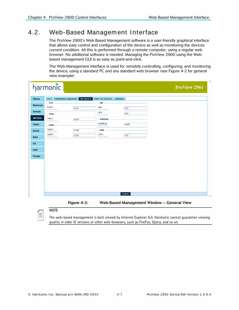
Chapter 4: ProView 2900 Control Interfaces Web-Based Management Interface
© Harmonic Inc. Manual p/n MAN-IRD-29XX 4-7 ProView 2900 Series/SW Version 1.9.9.4
4.2. Web-Based Management Interface The ProView 2900’s Web-Based Management software is a user-friendly graphical interface that allows easy control and configuration of the device as well as monitoring the devices current condition. All this is performed through a remote computer, using a regular web browser. No additional software is needed. Managing the ProView 2900 using the Web-based management GUI is as easy as point-and-click.
The Web-Management interface is used for remotely controlling, configuring, and monitoring the device, using a standard PC and any standard web browser (see Figure 4-2 for general view example).
Figure 4-2: Web-Based Management Window – General View
NOTE
The web-based management is best viewed by Internet Explorer 6.0. Harmonic cannot guarantee viewing quality in older IE versions or other web-browsers, such as FireFox, Opera, and so on.

Chapter 4: ProView 2900 Control Interfaces Web-Based Management Interface
© Harmonic Inc. Manual p/n MAN-IRD-29XX 4-8 ProView 2900 Series/SW Version 1.9.9.4
4.2.1. Controls and Displays The web-based management is divided into menus and submenus. Each menu's sub-menu displays (in an explorer window) a list of parameters related to the menu. In case of any additional parameters, such as advanced configuration parameters, another parameter-section is displays in the explorer window.
The web-based management is divided into display sections for an easy orientation and to offer a user-friendly control interface. The following paragraphs detail the different sections:
4.2.1.1. Title A static title to the web-based management, displays the Harmonic logo and the device's type (ProView 2961, see example in Figure 4-2).
4.2.1.2. Menu and Sub-Menu Tabs The tabs surround the explorer window section (see the following paragraph). The menu tabs are displayed at all times. The sub-menu tabs are dynamic, and change according to the selected menu. For example, 'Service' main menu holds the 'TV 1', 'Prefered Language' and other tabs, allowing the user to select respective configuration menus. (See tabs example in Figure 4-2).
The main-menu tabs are light-blue tabs that allow the user to select one of the main menus in the ProView 2900 (such as Video, Audio, Unit, and so on). The main-menu tabs are listed at the left-side of the explorer-window section. A selected main-menu tab changes its color from light-blue to darker blue. The sub-menu tabs are light-blue tabs that allow the user to select one of the specific sub-menus available in the selected menu.
4.2.1.3. Status Menu The Status menu, located under the 'Status' tab, displays a read-only table. The table details information regarding the various services provided by the unit (see Figure 4-3).
Figure 4-3: ProView 2900 Web-Based Management Status Menu (Example)
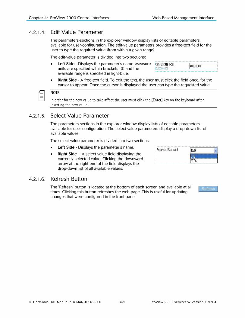
Chapter 4: ProView 2900 Control Interfaces Web-Based Management Interface
© Harmonic Inc. Manual p/n MAN-IRD-29XX 4-9 ProView 2900 Series/SW Version 1.9.9.4
4.2.1.4. Edit Value Parameter The parameters-sections in the explorer window display lists of editable parameters, available for user-configuration. The edit-value parameters provides a free-text field for the user to type the required value (from within a given range).
The edit-value parameter is divided into two sections:
• Left Side - Displays the parameter's name. Measure units are specified within brackets ([]) and the available range is specified in light-blue.
• Right Side - A free-text field. To edit the text, the user must click the field once, for the cursor to appear. Once the cursor is displayed the user can type the requested value.
NOTE
In order for the new value to take affect the user must click the [Enter] key on the keyboard after inserting the new value.
4.2.1.5. Select Value Parameter The parameters-sections in the explorer window display lists of editable parameters, available for user-configuration. The select-value parameters display a drop-down list of available values.
The select-value parameter is divided into two sections:
• Left Side - Displays the parameter's name.
• Right Side – A select-value field displaying the currently-selected value. Clicking the downward-arrow at the right-end of the field displays the drop-down list of all available values.
4.2.1.6. Refresh Button The 'Refresh' button is located at the bottom of each screen and available at all times. Clicking this button refreshes the web-page. This is useful for updating changes that were configured in the front-panel.

Chapter 4: ProView 2900 Control Interfaces Web-Based Management Interface
© Harmonic Inc. Manual p/n MAN-IRD-29XX 4-10 ProView 2900 Series/SW Version 1.9.9.4
4.2.2. Initializing the Web-Based Management
4.2.2.1. Setting the Web-Management Address Setting the Web management connection irequires setting the Ethernet Port parameters.
To access the Ethernet Management Port menu in the front panel control interface, go to ConfigurationUnitEthernet.
The following figure illustrates the Ethernet menu:
Ethernet 1-2-8-3
1 MAC Address 00-58-34-25-95-67
2 IP Address 010.008.000.216
3 Network Mask 255.255.255.000
4 Default Gateway 010.008.000.001
NOTE
In order to avoid any errors and faults, Harmonic recommends all Ethernet configurations to be preformed through the front-panel.
A. To set the IP Address:
1. Access the IP Address edit screen. IP Address.
2. Enter a valid IP Address. Verify that the entered IP address is not allocated to any other device.
B. To set the Subnet Mask:
1. Access the Subnet Mask edit screen. Subnet Mask.
2. Enter a valid subnet mask.
C. To set the Default Gateway:
1. Access the Default Gateway edit screen. Default Gateway
2. Enter a valid Default Gateway. Verify that the IP Address (set in the procedure A) is correlated with the Default Gateway address.
4.2.2.2. Launching the Web-Management Once the IP definitions are set according to the network, the user can access the web-based management interface.
To launch the web-management, enter the ProView 2900 IP Address in the Address field, in the following format: http://xxx.xxx.xxx.xxx (where xxx.xxx.xxx.xxx is the IP address of the Management port).
Once the web-management is displayed, the address changes to http://xxx.xxx.xxx.xxx/home.asp.
NOTE
The web-based management is supported and can be operated through most web browsers. However, Harmonic recommends Internet Explorer 6.0 and higher for optimal operation.

Chapter 4: ProView 2900 Control Interfaces Web-Based Management Interface
© Harmonic Inc. Manual p/n MAN-IRD-29XX 4-11 ProView 2900 Series/SW Version 1.9.9.4
4.2.2.3. Accessing the Web-Management To access the web-based management, user-name and password must be entered. The default values are provided with the equipment.
NOTE
It is warmly recommended to change the default user name and password immediately after installing the equipment.
Enter your user name and password in the access box. Press Submit to confirm or Clear to start over. For password change see section 14.3
Once the initialization is complete and the web-management is displayed, the user can set up the system. For details on the web-management operation, see Chapter 5.

© Harmonic Inc. Manual p/n MAN-IRD-29XX 5-1 ProView 2900 Series/SW Version 1.9.9.4
Chapter 5 Operation and Management
This chapter details managing the ProView 2900 locally, from its Front Panel interface and remotely, from its Web Management interface.
The Front Panel control interface contains all the existing ProView 2900 control parameters, while the Web management interface allows easy access to the same parameters from a remote computer. Therefore the description of these two interfaces is interwined and brought together in this chapter.
5.1. ProView 2900 Root Menu The ProView 2900 managing functions are divided into three main groups;
• Preset, where the user can create, store and manage up to 50 different user-defined setups (for details, see Section 5.2).
• Configuration, where the user may configure the ProView 2900 control parameters (for details, see Section 5.3 and Chapters 6 and up).
• Status, where the user can monitor the status of the ProView 2900 (for details, see Section 5.4).
All ProView 2900 management functions are organized within navigation menus, sub-menus and edit menus, categorized according to parameters type and affected interfaces. The Root menu is a general name for the initial screen enabling access to all menus
• The Front Panel "Root menu" is the first menu after the initial idle screen, and allows access to the front panel main menus (see details in paragraph 5.1.1).
• The Web-Management "Root menu" is the main screen, a working space displaying all menu tabs and their parameters and settings in the Explorer window (see details in paragraph 5.1.2).
5.1.1. ProView 2900 Front Panel Root Menu The front panel menu tree begins with the Root menu, which is a menu-navigation screen that leads to the three main basic menus; Preset, Configuration and Status.
The following figure is a ProView 2900 Front Panel Root menu:
Root
1 Preset
2 Configuration
3 Status
Figure 5-1 illustrates the ProView 2900 front panel tree structure from the Root menu.

Chapter 5: Operation and Management ProView 2900 Root Menu
© Harmonic Inc. Manual p/n MAN-IRD-29XX 5-2 ProView 2900 Series/SW Version 1.9.9.4
Figure 5-1: ProView 2900 Front Panel Root Menu Tree

Chapter 5: Operation and Management ProView 2900 Preset Menu
© Harmonic Inc. Manual p/n MAN-IRD-29XX 5-3 ProView 2900 Series/SW Version 1.9.9.4
5.1.2. ProView 2900 Web Manager Main Screen The ProView 2900 Web Manager Main screen is the work space of the web-management user (see Figure 5-2).
Figure 5-2: Web Manager – Main Menu Example
The tabs aligned to the left of the Explorer window (Status, Receiver, Audio, and so on) are the menu tabs, displaying all main menus of the IRD-2900.
The tabs arrayed at the top of the Explorer window (Audio 1, Audio 2, and so on) are the sub-menu tabs. These tabs are displayed specifically according to the selected menu tab. Selecting a sub-tab displays its general parameters and other available parameter sections in the Explorer window.
5.2. ProView 2900 Preset Menu The ProView 2900 allows creating, storing and managing up to 50 different user-defined setups. Each setup stores the following parameters:
• Front-End - (Satellite, IP, ATM, ASI) all parameters.
• Service (Dual for ProView 299x or Single for ProView 298x-and ProView 296x) selected parameters.
• Audio- - Decode mode and Volume parameters.
• CAS - BISS keys (mode and keys).
NOTES
The ProView 2900 configuration includes all parameters detailed in section 5.3, however, a Setup includes only the parameters mention above.
The setups are configurable through the front panel, Web-interface, CLI and SNMP.

Chapter 5: Operation and Management ProView 2900 Preset Menu
© Harmonic Inc. Manual p/n MAN-IRD-29XX 5-4 ProView 2900 Series/SW Version 1.9.9.4
To access the Preset menu through the front panel, go to RootPreset.
The following figure shows the front panel Preset menu:
Preset 1-1
1 Recall
2 Save Current
3 Rename
4 Delete
5 Delete All OFF
To access the Preset menu through the web-interface from the management bar, click on the Preset tab. The following figure shows the web-interface Preset menu:
The Preset menu consists of the following five submenus (see menu tree structure in ):
• Recall – For details see section 5.2.1.
• Save current – For details see section 5.2.2.
• Rename – For details see section 5.2.3.
• Delete – For details see section 5.2.4.
• Delete all – For details see section 5.2.5 (front-panel only).

Chapter 5: Operation and Management ProView 2900 Preset Menu
© Harmonic Inc. Manual p/n MAN-IRD-29XX 5-5 ProView 2900 Series/SW Version 1.9.9.4
5.2.1. Recall Preset Recall submenu allows loading saved presets from the unit's non-volatile storage.
TO RECALL A PRESET THOUGH THE FRONT PANEL:
1. To access the Preset menu from the front panel go to RootPresetRecall.
The Recall screen lists all stored presets and allows selecting a preset to recall. The following figure shows the front panel Recall screen:
Name
1 Default
2 Setup_1
3 Setup_2
4 Setup_3
2. Select one of the listed presets by using the [Up], [Down] and [ENTER] keys.
When selecting a preset to recall – the following screen appears: This screen shows the selected preset name at its title and the option Recall.
Setup_1
1 RECALL
3. Select the RECALL submenu tab.
NOTE
When selecting a preset, the front panel's orange warning light might lit until the unit is synced with the new setup applied.
TO RECALL A PRESET THROUGH THE WEB-INTERFACE:
1. From the management bar, click the Preset tab.
2. Click Recall tab.
3. Open the Recall drop-down menu. From the list select a preset to recall.

Chapter 5: Operation and Management ProView 2900 Preset Menu
© Harmonic Inc. Manual p/n MAN-IRD-29XX 5-6 ProView 2900 Series/SW Version 1.9.9.4
5.2.2. Save Current Preset The ProView 2900 can store up to 10 different setups. Save Current submenu allows saving the unit's current setup. To access the Save Current menu through the front panel, go to RootPresetSave Current.
The following figure shows the front panel Save Current submenu screen:
Save Current 1-1
1 Overwrite Existing
2 New Name
To access the Save menu from the web-interface, go to PresetSave.
Save Current menu includes two options:
Overwrite Existing –For details see section
5.2.2.1.
New Name- –For details see section 5.2.2.2.
NOTE
Harmonic recommends storing the default manufacture's setup as a preset.
5.2.2.1. Overwrite an Existing Preset The Overwrite Existing option allows saving the unit's current setup over a stored one.
TO OVERWRITE AN EXISTING PRESET THROUGH THE FRONT PANEL:
1. Access the Overwrite Existing screen. From the front panel go to RootPresetSave Current Overwrite Existing.
The following figure shows the front panel Overwrite Existing screen:
Name
1 Default
2 Setup_1
3 Setup_2
4 Setup_3
The Overwrite Existing screen lists all stored presets and allows selecting a preset to overwrite.
2. Select one of the listed presets by using the [Up], [Down] and [ENTER] keys.
When selecting a preset to overwrite – the following screen appears:
Setup_1
1 OVERWRITE
3. Select OVERWRITE.

Chapter 5: Operation and Management ProView 2900 Preset Menu
© Harmonic Inc. Manual p/n MAN-IRD-29XX 5-7 ProView 2900 Series/SW Version 1.9.9.4
TO OVERWRITE AN EXISTING PRESET THROUGH THE WEB-INTERFACE:
1. From the management bar, click on the Preset tab.
2. Click on Save tab.
3. Open the Overwrite Existing drop-down menu. From the list select a preset to overwrite.
5.2.2.2. Name a New Preset New Name option allows saving the unit's current setup under a new name.
TO NAME A NEW PRESET THROUGH THE FRONT PANEL:
1. Access the New Name screen. From the front panel go to RootPresetSave Current New Name.
The following figure shows the front panel New Name edit screen:
New Name
|
3. Name the preset by using the keypad. To select a character, use the [Up] and [Down] keys. To move between the characters, use the [LEFT] and [RIGHT] keys. To save, press [ENTER].
TO NAME A NEW PRESET THROUGH THE WEB-INTERFACE:
1. From the management bar, click on the Preset tab.
2. Click on Save tab.
3. Type a name for the preset in the New-Name textbox.
4. Press [ENTER] to finish.

Chapter 5: Operation and Management ProView 2900 Preset Menu
© Harmonic Inc. Manual p/n MAN-IRD-29XX 5-8 ProView 2900 Series/SW Version 1.9.9.4
5.2.3. Rename Preset The Rename submenu allows editing a stored preset name.
TO RENAME A PRESET THROUGH THE FRONT PANEL:
1. Access the Overwrite Existing screen. From the front panel go to RootPresetRename.
The following screen appears, lists all stored presets and allows selecting a preset to rename.
Name
1 Default
2 Setup_1
3 Setup_2
4 Setup_3
2. Select one of the listed presets by using the [Up], [Down] and [ENTER] keys.
When selecting a preset to rename – the Rename edit screen appears:
Rename
Setup_1
3. Name the preset by using the keypad. To change a character, use the [Up] and
[Down] keys. To move between the characters, use the [LEFT] and [RIGHT] keys. To save, press [ENTER].
TO RENAME A PRESET THROUGH THE WEB-INTERFACE:
1. From the management bar, click on the Preset tab.
2. Click on Rename tab.
3. Open the Existing Configuration drop-down menu. From the list select a preset to rename.
4. Type a new name for the preset in the New-Name textbox.

Chapter 5: Operation and Management ProView 2900 Preset Menu
© Harmonic Inc. Manual p/n MAN-IRD-29XX 5-9 ProView 2900 Series/SW Version 1.9.9.4
5.2.4. Delete Preset The Delete submenu allows removing stored preset.
TO DELETE A PRESET THROUGH THE FRONT PANEL:
1. Access the Delete screen. From the front panel go to RootPresetSave Current Delete.
The following screen appears, lists all stored presets and allows selecting a preset to delete.
Name
1 Default
2 Setup_1
3 Setup_2
4 Setup_3
2. Select one of the listed presets by using the [Up], [Down] and [ENTER] keys.
When selecting a preset to delete – the following screen appears:
Setup_1
1 DELETE
3. Select DELETE.
TO DELETE A PRESET THROUGH THE WEB-INTERFACE:
1. From the management bar, click on the Preset tab.
2. Click on Delete tab.
3. Open the Delete drop-down menu. From the list select a preset to delete.
5.2.5. Delete All Presets (Front Panel Only) The Delete All submenu allows removing all stored preset configurations.
TO DELETE ALL PRESETS THROUGH THE FRONT PANEL:
1. Access the Delete screen. From the front panel go to RootPresetSave Current Delete All.
The following figure shows the front panel Delete All screen:
Delete All
1 OFF
1 ON
Save Current menu includes two options:OFF (disables the function) and ON to delete all stored presets.
2. Select ON.

Chapter 5: Operation and Management Configuration
© Harmonic Inc. Manual p/n MAN-IRD-29XX 5-10 ProView 2900 Series/SW Version 1.9.9.4
5.3. Configuration The Configuration menu screen allows the user to manage the ProView 2900 through the Front Panel and the Web Manager.
To access the ProView 2900 Configuration menu from the Front Panel, select RootConfiguration. The ProView 2900 Configuration menu is displayed in the following menu:
Configuration 1-2
1 Receiver
2 Stream
3 Service
4 Video
5 Audio
6 Data
7 GenLock
8 Conditional Access
9 Unit
• Receiver (For details, see Chapter 6). The Receiver Configuration menu manages the Receiver Front-End module, according to receiver type installed in the ProView 2900.
• Stream (For details, see Chapter 7). The Stream Configuration menu manages the parameters of the demodulated transport stream.
• Service (For details, see Chapter 8). The Service Configuration menu manages the service parameters of the demodulated stream.
• Video (For details, see Chapter 1). The Video Configuration menu manages the video parameters of the demodulated stream.
• Audio (For details, see Chapter 10). The Audio Configuration menu manages the audio parameters of the demodulated stream.
• Data (For details, see Chapter 11). The Data Configuration Menu manages the data parameters of the output stream.
• GenLock (For details, see Chapter 12). The GenLock configuration menu is used for synchronizing the ProView 2900 with an external video input.
• Conditional Access (For details, see Chapter 13). The Conditional Access (CA) Configuration menu manages CA parameters of the demodulated stream.
• Unit (For details, see Chapter 14). The Unit Configuration menu manages the ProView 2900 unit related parameters.
NOTE
Sub-menus parameters may be vary from one model to another according to the ProView 2900 technical specifications and licensing.

Chapter 5: Operation and Management ProView 2900 Status Menu
© Harmonic Inc. Manual p/n MAN-IRD-29XX 5-11 ProView 2900 Series/SW Version 1.9.9.4
NOTE
The web does not display a special Configuration Menu. Instead, configuring the encoder parameters are done from the RVP-2900 Web Management root screen, in which the previously mentioned menus are displayed as tabs.
The following example displays the ProView 2900 Web Management screen.
5.4. ProView 2900 Status Menu The ProView 2900 allows the user to monitor the status of different parameters using the front panel or the web-management.
To access the ProView 2900 Status menu, select Status from the Root menu.
The ProView 2900 Status menu is displayed in the following menu navigation screen:
Status 1-3
1 Receiver
2 Stream
3 Service
4 Video
5 Audio
6 Data
7 GenLock
8 Conditional Access
9 Unit

Chapter 5: Operation and Management ProView 2900 Status Menu
© Harmonic Inc. Manual p/n MAN-IRD-29XX 5-12 ProView 2900 Series/SW Version 1.9.9.4
Figure 5-3: ProView 2900 Status Menu Tree Structure

Chapter 5: Operation and Management ProView 2900 Status Menu
© Harmonic Inc. Manual p/n MAN-IRD-29XX 5-13 ProView 2900 Series/SW Version 1.9.9.4
The following example displays the Web management Status monitoring screen.
5.4.1. Receiver Status The Receiver Status screen displays the main Receiver parameter current values. The following paragraphs detail the Status screen of each available receiver module type (DVB-S, DVB-S2, DSNG and IP Front End interfaces).
To enter the Receiver Status menu in the front panel, go to StatusReceiver (independently of receiver module type).
5.4.1.1. DVB-S Receiver Status To access the DVB-S Receiver status screen in the front panel control interface go to StatusReceiver.
NOTE
The LNB L.O. Frequency parameter is activated when the Ku and C-Band is selected.
The following screen displays the DVB-S Receiver Status menu:
Receiver 1-2-1
1 Signal Quality 100[%]
2 C/N 19.69[dB]
3 Eb/N0 09.94[dB]
4 Link Margin +04.9[dB]
5 BER 0.0e-7
6 Frequency Tune 1.068000[GHz]
7 Frequency Offset +02214[KHz]
8 FEC Rate 5/6
9 Spectral Inversion NORMAL

Chapter 5: Operation and Management ProView 2900 Status Menu
© Harmonic Inc. Manual p/n MAN-IRD-29XX 5-14 ProView 2900 Series/SW Version 1.9.9.4
Figure 5-4 displays the corresponding DVB-S Status Web management screen.
Figure 5-4: ProView 2900 DVB-S Receiver Status Screen
The available options are:
• Signal Quality – Qualitative indicator of the received signal C/N relative to the maximum C/N that can be measured without forcing the receiver to saturation. The signal quality is calculated by: SQ[%]=C/N [dB]/36 *100
Signal Quality
100 [%]
< 000 - 100 >
• C/N – Shows the Carrier to Noise ratio.
• Eb/N0 – Received signal Eb/N0 measurement
• Link Margin – Estimated C/N of the received signal relative to the C/N in EN 300-421 for a given FEC rate
• BER – Uncorrected FEC bits errors. BER is measured over 107 symbols.
• Frequency Tune – The value is dependent on the mode selected in RootConfiguration Receiver Freq Drift Compensation (see Section 6.2).
• When Frequency Drift Compensation is set On, the value of the frequency tune displays the frequency of the incoming signal after frequency offset is set Off.
• When Frequency Drift Compensation is set Off, the value of the frequency tune displays the actual frequency.
NOTE
Displayed frequencies are L-Band frequencies.
• Frequency Offset - Displays the offset from the frequency as was set in Configuration Receiver Frequency (see Section 6.2).
• When Frequency Drift Compensation is set to On, the frequency offset displays the value 0.
• When Frequency Drift Compensation is set to Off, frequency offset displays the value of the offset from the tuned frequency in KHz.
• FEC Rate – When FEC Rate mode is set to automatic (see FEC Rate parameter in section 6.2), the value displayed is selected by the ProView 2900. The FEC rate can also be configured manually to a specific rate by the operator.
• Spectral Inversion – When the Spectral Inversion mode is set to automatic (see Section 6.2), the value displayed is the one selected by the device. Otherwise, this parameter displays the Spectral Inversion method that was selected manually.
5.4.1.2. DVB-S2 Receiver Status To access the DVB-S2 Receiver status screen in front panel control interface go to StatusReceiver.

Chapter 5: Operation and Management ProView 2900 Status Menu
© Harmonic Inc. Manual p/n MAN-IRD-29XX 5-15 ProView 2900 Series/SW Version 1.9.9.4
The following screen displays the DVB-S2 Receiver status menu:
Receiver 1-3-1
1 Signal Quality 94[%]
2 C/N -8.00[dBm]
3 Link Margin 21.10[dB]
4 MPEG PER 0.0e-7
5 Frequency Tune 1.000000 [GHz]
6 Frequency Offset +00011[KHz]
7 Modulation DVBS2-N-QPSK
8 FEC Rate 8/9
9 Roll-off 35%
10 Spectral Inversion NORMAL
Figure 5-5 displays the corresponding DVB-S2 Status Web management screen.
Figure 5-5: ProView 2900 DVBS2 Receiver Status Screen
The available options are:
• Signal Quality – Qualitative indicator of the received signal C/N relative to the maximum C/N that can be measured without forcing the receiver to saturation. The signal quality is calculated by: SQ[%]=C/N [dB]/36 *100
Signal Quality
94 [%]
< 000 - 100 >
• C/N – Shows the Carrier to Noise ratio.
• Link Margin – Shows actual signal reception strength.
• MPEG PER – Show packet error rate.
• Frequency Tune – This parameter points out the optimal frequency checked by the ProView 2900 for obtaining the highest quality of the received signal.
• Frequency Offset – displays the deviation between the frequency inserted by the operator and the frequency that was indicated by the Frequency Tune.
• Modulation – displays the configured modulation method
• FEC Rate – reports the selected FEC rate
• Roll Off – the configured Roll-Off factor value
• Spectral Inversion – When the Spectral Inversion mode is set to automatic (see Section 6.2), the value displayed is the one selected by the device. Otherwise, this parameter displays the Spectral Inversion method that was selected manually.
NOTE
All displayed frequencies are in L-Band.
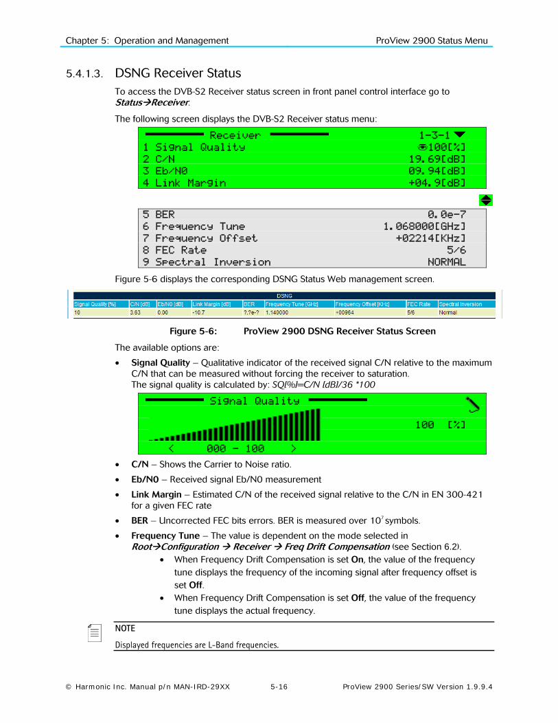
Chapter 5: Operation and Management ProView 2900 Status Menu
© Harmonic Inc. Manual p/n MAN-IRD-29XX 5-16 ProView 2900 Series/SW Version 1.9.9.4
5.4.1.3. DSNG Receiver Status To access the DVB-S2 Receiver status screen in front panel control interface go to StatusReceiver.
The following screen displays the DVB-S2 Receiver status menu:
Receiver 1-3-1
1 Signal Quality 100[%]
2 C/N 19.69[dB]
3 Eb/N0 09.94[dB]
4 Link Margin +04.9[dB]
5 BER 0.0e-7
6 Frequency Tune 1.068000[GHz]
7 Frequency Offset +02214[KHz]
8 FEC Rate 5/6
9 Spectral Inversion NORMAL
Figure 5-6 displays the corresponding DSNG Status Web management screen.
Figure 5-6: ProView 2900 DSNG Receiver Status Screen
The available options are:
• Signal Quality – Qualitative indicator of the received signal C/N relative to the maximum C/N that can be measured without forcing the receiver to saturation. The signal quality is calculated by: SQ[%]=C/N [dB]/36 *100
Signal Quality
100 [%]
< 000 - 100 >
• C/N – Shows the Carrier to Noise ratio.
• Eb/N0 – Received signal Eb/N0 measurement
• Link Margin – Estimated C/N of the received signal relative to the C/N in EN 300-421 for a given FEC rate
• BER – Uncorrected FEC bits errors. BER is measured over 107 symbols.
• Frequency Tune – The value is dependent on the mode selected in RootConfiguration Receiver Freq Drift Compensation (see Section 6.2).
• When Frequency Drift Compensation is set On, the value of the frequency tune displays the frequency of the incoming signal after frequency offset is set Off.
• When Frequency Drift Compensation is set Off, the value of the frequency tune displays the actual frequency.
NOTE
Displayed frequencies are L-Band frequencies.

Chapter 5: Operation and Management ProView 2900 Status Menu
© Harmonic Inc. Manual p/n MAN-IRD-29XX 5-17 ProView 2900 Series/SW Version 1.9.9.4
• Frequency Offset - Displays the offset from the frequency as was set in Configuration Receiver Frequency (see Section 6.2).
• When Frequency Drift Compensation is set to On, the frequency offset displays the value 0.
• When Frequency Drift Compensation is set to Off, frequency offset displays the value of the offset from the tuned frequency in KHz.
• FEC Rate – When FEC Rate mode is set to automatic (see FEC Rate parameter in section 6.2), the value displayed is selected by the ProView 2900. The FEC rate can also be configured manually to a specific rate by the operator.
• Spectral Inversion – When the Spectral Inversion mode is set to automatic (see Section 6.2), the value displayed is the one selected by the device. Otherwise, this parameter displays the Spectral Inversion method that was selected manually.
5.4.1.4. IP Receiver Status The IP Receiver status menu enables monitoring the main IP receiver parameters. It displays both static information (such as MPEGoIP port MAC Address) and live data (e.g. type of data encapsulation received, current bit rate, whether or not IP parameters are valid, etc.).
To access the IP Receiver status menu in the front panel interface go to StatusReceiver
The IP Receiver status menu as displayed on the ProView 2900 front panel screen:
Receiver 1-3-1
1 MPEGoIP Input 1
2 MPEGoIP Input 2
3 General
The available options are:
• MPEGoIP Input 1 – for monitoring receiver data arriving through the MPEGoIP IN1 interface
• MPEGoIP Input 2 - for monitoring receiver data arriving through the MPEGoIP IN2 interface
• General – for viewing general parameters values, such as software and hardware version number, IP configuration consistency, type of detected encapsulation, bit-rate of currently received data, etc.
The following paragraphs detail the IP Receiver Status sub menus.

Chapter 5: Operation and Management ProView 2900 Status Menu
© Harmonic Inc. Manual p/n MAN-IRD-29XX 5-18 ProView 2900 Series/SW Version 1.9.9.4
5.4.1.4.1. MPEGoIP Input 1
The following figure illustrates the MPEGoIP Input 1 menu as displayed on the ProView 2900 front panel screen:
MPEGoIP Input 1 1-3-1-1
1 MAC Address 00-78-34-25-9B-68
2 Physical Link Status Up/100Base-T/Full
Figure 5-7 displays the corresponding IP Receiver / MPEGoIP Status Web management screen.
Figure 5-7: ProView 2900 IP Receiver/MPEGoIP Status Screen
The IP Receiver/MPEGoIP Input 1 Status parameters are:
• MAC Address – MPEGoIP IN1 port MAC address. The MAC address is a unique, read-only address.
• Physical Link Status – current link status. The available options are: • Down – Physical link is down • Up – Physical link is up and connection is established • 10Base-T, 100Base-T – IP Port data input rate • Full – receiving in full duplex • Half – receiving in half duplex
NOTE
MPEGoIP Input 2 Status parameters are identical to those of MPEGoIP Input 1 Status and provide information on MPEGoIP IN2 data.
5.4.1.4.2. General
The IP receiver General status menu as displayed on the ProView 2900 front panel screen:
General 1-3-1-3
1 HW Revision 53
2 SW Version dd/mm/yy mj.mn 18/08/05 01.05
3 Configuration OK
4 Active Input 1
5 Encapsulation UDP
6 MPEG Packet Size 188
7 Rx Bitrate Current 33.792093 [MHz]
Figure 5-8 displays the corresponding IP Receiver/General Status Web management screen.
Figure 5-8: ProView 2900 IP Receiver/Status Status Screen
The IP Receiver/General menu parameters are:

Chapter 5: Operation and Management ProView 2900 Status Menu
© Harmonic Inc. Manual p/n MAN-IRD-29XX 5-19 ProView 2900 Series/SW Version 1.9.9.4
• HW Revision – FPGA hardware Revision
• SW Version – software date and software version
• Configuration – displays “OK” if receiver configuration is valid, or “Mismatch” if it has inconsistencies
• Active Input - the actual input active
• Receive Mode – displays “UDP” or “RTP” according to the type of received data
• MPEG Packet Size – size of received packets (in bytes). Can be either 188 or 204 bytes
• Rx Bitrate Current – current rate of received data (in MHz)

Chapter 5: Operation and Management ProView 2900 Status Menu
© Harmonic Inc. Manual p/n MAN-IRD-29XX 5-20 ProView 2900 Series/SW Version 1.9.9.4
5.4.2. Stream Status Menu The Stream status menu provides an extended menu of status monitoring options on the input stream.
To access the Stream status menu in the front panel control interface go to StatusStream.
The following screen displays the Stream status menu:
Stream 1-3-2
1 Quality
2 Information
Figure 5-9displays the corresponding Web management screen.
Figure 5-9: ProView 2900 Stream Status Screen
5.4.2.1. Quality The Quality Menu displays information about the quality of the Input Stream. To access the Quality Menu in the front panel control interface go to StatusStreamQuality.
The following screen displays the Quality menu:
Quality 1-3-2-1
1 Sync-Ox47 Loss 000007
2 Continuity Counter 000006
3 T.S Fifo Overflow 000000
4 T.S Error Indicator 000007
5 ASI Input NOT DETECT
6 RS-422 Input NOT DETECT
The Quality Menu parameters are:
• Sync-0x47 Loss – Counts the number of sync loss events
• Continuity Counter – Counts the number of a continuity of error events
• TS FIFO overflow – Counts the number of FIFO buffer events
• TS Error Indicator – Counts the number of MPEG packets that were received by the ProView 2900 and had the TS error indicator bit set
• ASI Input.-. Has three modes: • NOT DETECTED – No input • 188 DETECTED – MPEG packets without FEC • 204 DETECTED – MPEG packets with FEC
• RS-422 Input – Has three modes: • NOT DETECTED – No input.
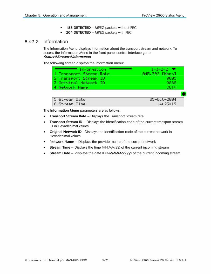
Chapter 5: Operation and Management ProView 2900 Status Menu
© Harmonic Inc. Manual p/n MAN-IRD-29XX 5-21 ProView 2900 Series/SW Version 1.9.9.4
• 188 DETECTED – MPEG packets without FEC. • 204 DETECTED – MPEG packets with FEC.
5.4.2.2. Information The Information Menu displays information about the transport stream and network. To access the Information Menu in the front panel control interface go to StatusStreamInformation.
The following screen displays the Information menu:
Information 1-3-2-2
1 Transport Stream Rate 045.792 [Mbps]
2 Transport Stream ID 0005
3 Original Network ID 0888
4 Network Name CCTV
5 Stream Date 05-Oct-2004
6 Stream Time 14:23:19
The Information Menu parameters are as follows:
• Transport Stream Rate – Displays the Transport Stream rate
• Transport Stream ID – Displays the identification code of the current transport stream ID in Hexadecimal values
• Original Network ID –Displays the identification code of the current network in Hexadecimal values
• Network Name – Displays the provider name of the current network
• Stream Time – Displays the time (HH:MM:SS) of the current incoming stream
• Stream Date – displays the date (DD-MMMM-YYYY) of the current incoming stream

Chapter 5: Operation and Management ProView 2900 Status Menu
© Harmonic Inc. Manual p/n MAN-IRD-29XX 5-22 ProView 2900 Series/SW Version 1.9.9.4
5.4.3. Service Status The Service Info is a section in the Status web-interface screen. It provides information of service's status and parameters.
Figure 5-10 displays the Service Status Web management screen.
Figure 5-10: ProView 2900 Service Status Screen
The following parameters are displayed:
• TV – This parameter indicates the active decoder as TV1 (or TV1/TV2 in case of a dual decoder unit).
• Service Name – This parameter displays the service's name.
• Service Type – This parameter indicates the service type: TV, Radio, TLTX, NVOD, MOSAIC, PAL, SECAM, MAC, FM, NTSC, and Data.
• Service ID – This parameter displays the service identification symbol [Hex].
• Service Mode - Indicates if the service is encrypted (CAS) or free to air (FTA).
• Active in PAT – this parameter indicates whether the service is included in the PAT table or not.
5.4.4. Video Status Menu The Video status menu displays the status of Video and VBI parameters. It provides an extended menu of status monitoring options on Video and VBI data. To access the Video status menu in the front panel control interface go to StatusVideo.
The following screen displays the Video Status menu:
Video 1-3-4
1 Video 1
2 VBI 1
3 OSD 1
Figure 5-11 displays the corresponding Web management screen.
Figure 5-11: ProView 2900 Video Status Screen
The Video status menu parameters are as follows:
• Video 1 / Video 2 (if applicable) – This group displays information about the video for Decoder #1 / Decoder #2 (see Section 9.2).
• VBI 1 / VBI 2 (if applicable) - This group displays information about the VBI for Decoder #1 / Decoder #2 (See Section 9.3).
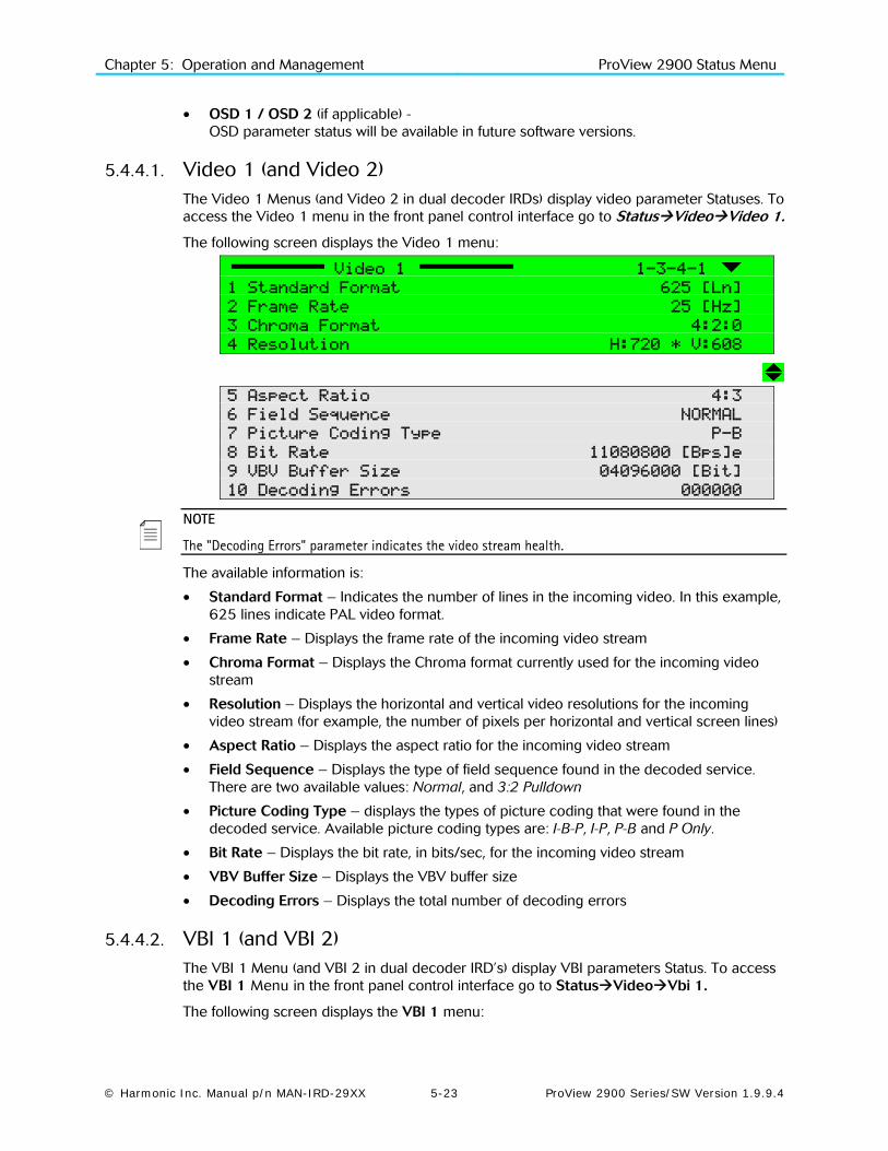
Chapter 5: Operation and Management ProView 2900 Status Menu
© Harmonic Inc. Manual p/n MAN-IRD-29XX 5-23 ProView 2900 Series/SW Version 1.9.9.4
• OSD 1 / OSD 2 (if applicable) - OSD parameter status will be available in future software versions.
5.4.4.1. Video 1 (and Video 2) The Video 1 Menus (and Video 2 in dual decoder IRDs) display video parameter Statuses. To access the Video 1 menu in the front panel control interface go to StatusVideoVideo 1.
The following screen displays the Video 1 menu:
Video 1 1-3-4-1
1 Standard Format 625 [Ln]
2 Frame Rate 25 [Hz]
3 Chroma Format 4:2:0
4 Resolution H:720 * V:608
5 Aspect Ratio 4:3
6 Field Sequence NORMAL
7 Picture Coding Type P-B
8 Bit Rate 11080800 [Bps]e
9 VBV Buffer Size 04096000 [Bit]
10 Decoding Errors 000000
NOTE
The "Decoding Errors" parameter indicates the video stream health.
The available information is:
• Standard Format – Indicates the number of lines in the incoming video. In this example, 625 lines indicate PAL video format.
• Frame Rate – Displays the frame rate of the incoming video stream
• Chroma Format – Displays the Chroma format currently used for the incoming video stream
• Resolution – Displays the horizontal and vertical video resolutions for the incoming video stream (for example, the number of pixels per horizontal and vertical screen lines)
• Aspect Ratio – Displays the aspect ratio for the incoming video stream
• Field Sequence – Displays the type of field sequence found in the decoded service. There are two available values: Normal, and 3:2 Pulldown
• Picture Coding Type – displays the types of picture coding that were found in the decoded service. Available picture coding types are: I-B-P, I-P, P-B and P Only.
• Bit Rate – Displays the bit rate, in bits/sec, for the incoming video stream
• VBV Buffer Size – Displays the VBV buffer size
• Decoding Errors – Displays the total number of decoding errors
5.4.4.2. VBI 1 (and VBI 2) The VBI 1 Menu (and VBI 2 in dual decoder IRD’s) display VBI parameters Status. To access the VBI 1 Menu in the front panel control interface go to StatusVideoVbi 1.
The following screen displays the VBI 1 menu:

Chapter 5: Operation and Management ProView 2900 Status Menu
© Harmonic Inc. Manual p/n MAN-IRD-29XX 5-24 ProView 2900 Series/SW Version 1.9.9.4
Vbi (1) 1-3-4-2
1 Video Fullness 020 [%]
2 E.S Fullness 012 [%]
3 E.S Top Num Lines 05 [Ln]
4 E.S Bottom Num Lines 05 [Ln]
The available information is:
• Video Fullness – Fullness level of the buffer containing VBIs derived from the video stream
• E.S Fullness – Fullness of the buffer containing VBIs derived from the elementary stream
• E.S Top Num Lines – Counts the number of E.S VBI lines in a field
• E.S Bottom Num Lines – Counts the number of E.S VBI lines in a field
5.4.4.3. OSD 1 (and OSD 2) This feature will be supported in the future software releases.
5.4.5. Audio Status Menu The Audio Status Menu displays information on the audio channels. To access the Audio Status Menu in the front panel control interface go to StatusAudio.
The following screen displays the Audio Status menu:
Audio 1-3-5
1 Audio 1
2 Audio 2
3 Audio 3
4 Audio 1
Select Audio 1 through 4. The Audio (1..4) Menu displays information on the audio decoding process. When Musicam mode is activated, the following screen is displayed:
Audio (1..4) 1-3-5-1
1 ID MPEG
2 Layer LAYER2
3 Bit Rate 129000 [Bps]
4 Sample Rate 48 [KHz]
5 Mode STEREO
6 Decoding Errors 000894
Figure 5-12 displays the corresponding Web management screen.
Figure 5-12: ProView 2900 Audio Status Screen

Chapter 5: Operation and Management ProView 2900 Status Menu
© Harmonic Inc. Manual p/n MAN-IRD-29XX 5-25 ProView 2900 Series/SW Version 1.9.9.4
NOTE
The "Decoding Errors" parameter indicates the video stream health.
When Dolby-AC3 mode is activated, the following screen is displayed:
Audio (1..4) 1-3-5-1
1 ID DOLBY AC3
2 Bit Rate 128000[Bps]
3 Sample Rate 48[KHz]
4 AC Mode 2/0 L,R STEREO
5 BS Mode COMPLETE MAIN
6 Decoding Errors 083914
When Linear PCM mode is activated, the screen below is displayed:
Audio (1..4) 1-3-5-1
1 ID LINEAR
2 Sample Rate 48 [KHz]
3 Bits per Sample 20 BITS
4 Channel ID 2
5 Output Mode 2/0 L,R
6 Decoding Errors 0003
NOTE
The Channel ID parameter value is according to the channel number of the AC3 header.
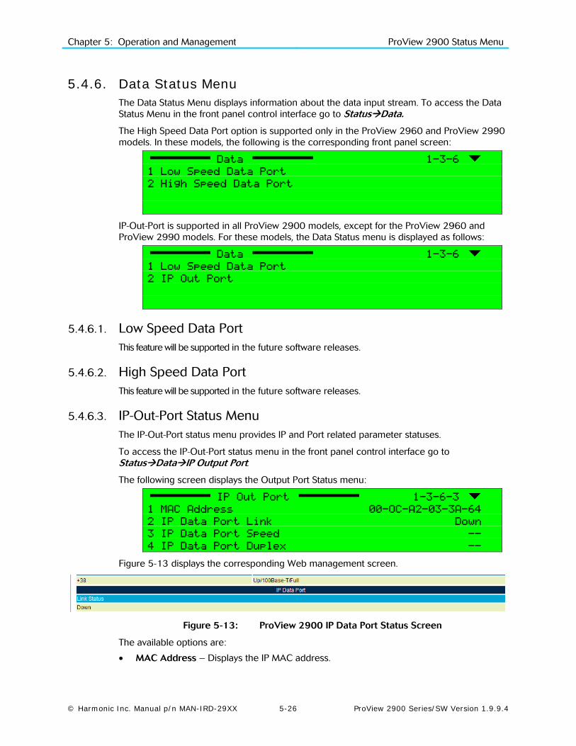
Chapter 5: Operation and Management ProView 2900 Status Menu
© Harmonic Inc. Manual p/n MAN-IRD-29XX 5-26 ProView 2900 Series/SW Version 1.9.9.4
5.4.6. Data Status Menu The Data Status Menu displays information about the data input stream. To access the Data Status Menu in the front panel control interface go to StatusData.
The High Speed Data Port option is supported only in the ProView 2960 and ProView 2990 models. In these models, the following is the corresponding front panel screen:
Data 1-3-6
1 Low Speed Data Port
2 High Speed Data Port
IP-Out-Port is supported in all ProView 2900 models, except for the ProView 2960 and ProView 2990 models. For these models, the Data Status menu is displayed as follows:
Data 1-3-6
1 Low Speed Data Port
2 IP Out Port
5.4.6.1. Low Speed Data Port This feature will be supported in the future software releases.
5.4.6.2. High Speed Data Port This feature will be supported in the future software releases.
5.4.6.3. IP-Out-Port Status Menu The IP-Out-Port status menu provides IP and Port related parameter statuses.
To access the IP-Out-Port status menu in the front panel control interface go to StatusDataIP Output Port.
The following screen displays the Output Port Status menu:
IP Out Port 1-3-6-3
1 MAC Address 00-OC-A2-03-3A-64
2 IP Data Port Link Down
3 IP Data Port Speed --
4 IP Data Port Duplex --
Figure 5-13 displays the corresponding Web management screen.
Figure 5-13: ProView 2900 IP Data Port Status Screen
The available options are:
• MAC Address – Displays the IP MAC address.

Chapter 5: Operation and Management ProView 2900 Status Menu
© Harmonic Inc. Manual p/n MAN-IRD-29XX 5-27 ProView 2900 Series/SW Version 1.9.9.4
• IP Data Port Link – Displays the status of the IP port (Up or Down).
• IP Data Port Speed – 10 Base-T, 100 Base-T
• IP Data Port Duplex – Displays the duplex operation mode of the IP port (Full or Half).
When the IP Data Port link status is down or when the IP Data Port is disconnected, the horizontal bars [--] are displayed.
5.4.7. GenLock Status This feature will be supported in future software releases.
5.4.8. Conditional Access Status Menu The Conditional Access status menu allows viewing conditional access parameters statuses.
To access the Conditional Access Status Menu in the front panel control interface go to StatusConditional Access
The following screen displays the Conditional Access Status menu:
Conditional Access 1-3-8
1 Common Interface
2 BISS
3 Embedded
Caution
The Conditional Access Status menu must be handled by qualified users who are familiar with the DVB-S2 standard and protocols.
5.4.8.1. Common Interface The Common Interface Menu displays information on the CAMs inserted to the ProView 2900 CI Slot. The status menu for Slot 1 and Slot 2 is identical unless one of the CI Slots is not equipped with a CAM.
To access the Common Interface Menu in the front panel control interface go to StatusConditional AccessCommon Interface.
The following screen displays the Common Interface Status menu:
Common Interface 1-3-8-1
1 Slot1
2 Slot2
The Slot (1..2) Menu displays information on a CAM in Slot (1..2).
To access the Slot 1 Menu in the front panel control interface go to StatusConditional AccessCommon InterfaceSlot 1.
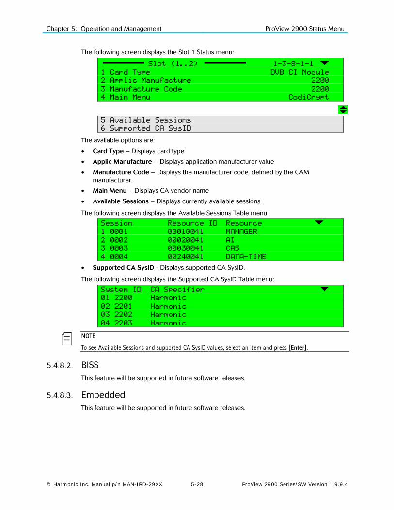
Chapter 5: Operation and Management ProView 2900 Status Menu
© Harmonic Inc. Manual p/n MAN-IRD-29XX 5-28 ProView 2900 Series/SW Version 1.9.9.4
The following screen displays the Slot 1 Status menu:
Slot (1..2) 1-3-8-1-1
1 Card Type DVB CI Module
2 Applic Manufacture 2200
3 Manufacture Code 2200
4 Main Menu CodiCrypt
5 Available Sessions
6 Supported CA SysID
The available options are:
• Card Type – Displays card type
• Applic Manufacture – Displays application manufacturer value
• Manufacture Code – Displays the manufacturer code, defined by the CAM manufacturer.
• Main Menu – Displays CA vendor name
• Available Sessions – Displays currently available sessions.
The following screen displays the Available Sessions Table menu:
Session Resource ID Resource
1 0001 00010041 MANAGER
2 0002 00020041 AI
3 0003 00030041 CAS
4 0004 00240041 DATA-TIME
• Supported CA SysID - Displays supported CA SysID.
The following screen displays the Supported CA SysID Table menu:
System ID CA Specifier
01 2200 Harmonic
02 2201 Harmonic
03 2202 Harmonic
04 2203 Harmonic
NOTE
To see Available Sessions and supported CA SysID values, select an item and press [Enter].
5.4.8.2. BISS This feature will be supported in future software releases.
5.4.8.3. Embedded This feature will be supported in future software releases.

Chapter 5: Operation and Management ProView 2900 Status Menu
© Harmonic Inc. Manual p/n MAN-IRD-29XX 5-29 ProView 2900 Series/SW Version 1.9.9.4
5.4.9. Unit Status Menu This menu displays the Unit Menu parameters status.To access the Unit menu in the front panel control interface go to StatusUnit.
The following screen displays the Unit Status menu:
Unit 1-3-9
1 Identity
2 Versions
3 Monitoring
5.4.9.1. Unit Identity The Identity Menu displays information regarding the ProView 2900 hardware. To access the Identity Menu in the front panel control interface go to StatusUnitIdentity
The following screen displays the Identity Status menu:
Identity 1-3-9-1
1 Configuration ID ProView 2983
2 Serial Number 00000920
3 Decoder Board SPN-29 REV-C
4 Front-End Board QPSK-29 REV-A
The available options are:
• Configuration ID – Displays the ProView 2900 software configuration model as recognized by the software.
• Serial Number – Displays the ProView 2900 serial number
• Decoder Board – Displays the hardware revision of the ProView 2900 main board
• Front-End Board – Displays the hardware revision of the ProView 2900 Front-End
Figure 5-14 displays the corresponding Web management screen.
Figure 5-14: Unit Identity Status Screen
5.4.9.2. Unit Versions The Version Menu displays information on the ProView 2900 software versions.
To access the Versions Menu in the front panel control interface go to StatusUnitVersions.
The following screen displays the Versions Status menu:
Versions 1-3-9-2
1 Boot Application 00.03
2 Main Application 00.07
3 Main Application Date Dec 19 2004
4 Main Application Time 15:50:26
The available options are:

Chapter 5: Operation and Management ProView 2900 Status Menu
© Harmonic Inc. Manual p/n MAN-IRD-29XX 5-30 ProView 2900 Series/SW Version 1.9.9.4
• Boot Application – Displays the boot application software version
• Main Application – Displays the main application software version
• Main Application Date – Displays the date when the main application was created
• Main Application Time – Displays the time when the main application was created
Figure 5-15 displays the corresponding Web management screen.
Figure 5-15: Unit – Versions Status Screen
5.4.9.3. Monitoring The Monitoring Menu displays temperature and management port statuses.
To access the Monitoring Menu in the front panel control interface go to StatusUnitMonitoring.
The following screen displays the Monitoring Status menu:
Monitoring 1-3-9-3
1 Temperature +20 [C]
2 Management Link Status UP/100Base-T/Full
The available options are:
• Temperature – Displays the internal temperature of the ProView 2900 as measured by the temperature sensor
• Management Link Status – Displays the status of the Management Port link.
Figure 5-16 displays the corresponding Web interface screen.
Figure 5-16: Unit – Monitoring Status Screen
5.4.9.4. Licensing The Licensing screen displays all ProView 2900 licensed features and their operational status.
Licensing 1-3-9-4
01 ASI Input YES
02 ASI Output YES
03 MPEGoIP/MPE Output NO
04 Audio 3 NO

Chapter 5: Operation and Management ProView 2900 Status Menu
© Harmonic Inc. Manual p/n MAN-IRD-29XX 5-31 ProView 2900 Series/SW Version 1.9.9.4
05 Audio 4 YES
06 LSD (RS-232) YES
07 DOLBY Audio1 Decoding YES
08 DOLBY Audio2 Decoding YES
09 DOLBY Audio3 Decoding YES
10 DOLBY Audio4 Decoding YES
11 Linear Audio 1 Decoding YES
12 Linear Audio 2 Decoding YES
13 Linear Audio 3 Decoding YES
14 Linear Audio 4 Decoding YES
15 PID Filtering YES
16 Advanced CI (MPEG4,CID) YES
17 DVBS2 Advanced Modulation YES
18 DVBS2 Dual TS YES
Figure 5-17 displays the corresponding Unit Licensing Web management screen.
Figure 5-17: Unit Licensing Web-Management Screen

© Harmonic Inc. Manual p/n MAN-IRD-29XX 6-1 ProView 2900 Series/SW Version 1.9.9.4
Chapter 6 Receiver Configuration
This chapter details the Receiver configuration functions provided to the ProView 2900 User.
6.1. ProView 2900 Receiver Configuration Menu Tree The purpose of the receiver module is to single out a selected Transport Stream from the transmission that reaches the ProView 2900 inputs, to demodulate it, and pass on the digital transport stream to the decoder module.
Different networks require various receiver types. According to its licensing, the ProView 2900 supports the following types of receivers:
1. Satellite Receiver Modules:
• DVB-S Receiver Module The configuration parameters of the DVB-S receiver module are detailed in Section 6.2.1.
• DVB-S2 Receiver Module The configuration parameters of the DVB-S2 receiver module are detailed in Section 6.2.2.
• DSNG Receiver Module The configuration parameters of the DSNG receiver module are detailed in Section 6.2.3.
2. IP Receiver Module - The configuration parameters of the IP receiver module are detailed in Section 6.3.
3. ATM Receiver Module - The configuration parameters of the ATM receiver module are detailed in Section 6.4.
To access the Receiver Configuration menu using the front panel, select ConfigurationReceiver in the Front Panel menu tree or the Receiver option in the Web Manager main menu (independently of the receiver module type).
6.2. Satellite Receiver Configuration This section details the ProView 2900 Front Panel and Web Manager menus that enable configuring the Satellite Receiver in a ProView 2900 Satellite Front End device.The ProView 2900 supports three Sattelite Front-End Receiver modules; DVB-S, DVB-S2 and DSNG.
Figure 6-1 illustrates the structure of the configuration tree menu for the Satellite Receivers.

Chapter 6: Receiver Configuration Modules Satellite Receiver Configuration
© Harmonic Inc. Manual p/n MAN-IRD-29XX 6-2 ProView 2900 Series/SW Version 1.9.9.4
Figure 6-1: Satellite Receiver Configuration Menu Screen

Chapter 6: Receiver Configuration Modules Satellite Receiver Configuration
© Harmonic Inc. Manual p/n MAN-IRD-29XX 6-3 ProView 2900 Series/SW Version 1.9.9.4
6.2.1. DVB-S Receiver Configuration This section details the front panel menus that enable configuring the DVB-S receiver in a ProView 2900 DVB-S front end device. The following is the DVB-S Receiver Configuration menu as displayed on the ProView 2900 front panel screen:
Receiver 1-2-1
01 Frequency 1.068000 [GHz]
02 Symbol Rate 29.818000 [Mbaud]
03 FEC Rate AUTOMATIC
04 Spectral Inversion AUTOMATIC
05 LNB Power Supply 18V (HORIZONTAL)
06 LNB 22 KHz OFF (Low Band)
07 Freq Drift Compensation OFF
08 LNB L.O. Type C band
09 LNB L.O. Frequency 5150000
10 Frequency Range L BAND
11 Frequency Scan OFF
Figure 6-2 displays the corresponding Web Management menu screen for the DVB-S Receiver Parameters.
Figure 6-2: DVB-S Receiver Parameters Menu Screen
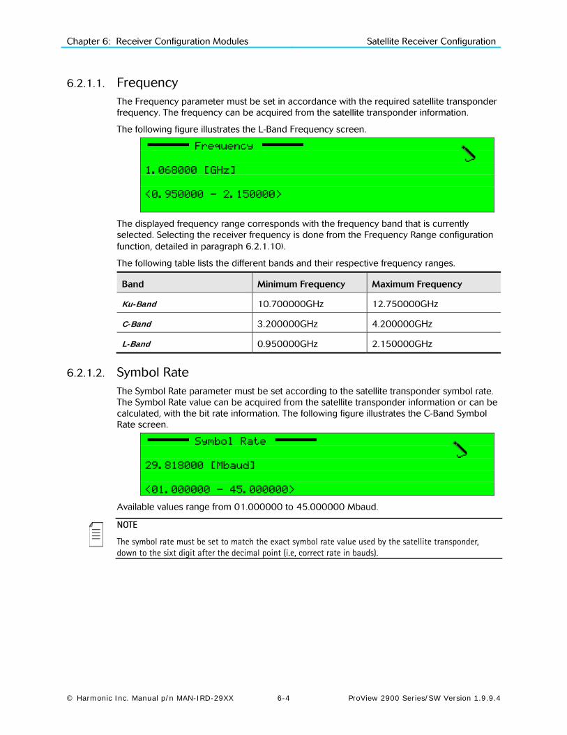
Chapter 6: Receiver Configuration Modules Satellite Receiver Configuration
© Harmonic Inc. Manual p/n MAN-IRD-29XX 6-4 ProView 2900 Series/SW Version 1.9.9.4
6.2.1.1. Frequency The Frequency parameter must be set in accordance with the required satellite transponder frequency. The frequency can be acquired from the satellite transponder information.
The following figure illustrates the L-Band Frequency screen.
Frequency
1.068000 [GHz]
<0.950000 - 2.150000>
The displayed frequency range corresponds with the frequency band that is currently selected. Selecting the receiver frequency is done from the Frequency Range configuration function, detailed in paragraph 6.2.1.10).
The following table lists the different bands and their respective frequency ranges.
Band Minimum Frequency Maximum Frequency
Ku-Band 10.700000GHz 12.750000GHz
C-Band 3.200000GHz 4.200000GHz
L-Band 0.950000GHz 2.150000GHz
6.2.1.2. Symbol Rate The Symbol Rate parameter must be set according to the satellite transponder symbol rate. The Symbol Rate value can be acquired from the satellite transponder information or can be calculated, with the bit rate information. The following figure illustrates the C-Band Symbol Rate screen.
Symbol Rate
29.818000 [Mbaud]
<01.000000 - 45.000000>
Available values range from 01.000000 to 45.000000 Mbaud.
NOTE
The symbol rate must be set to match the exact symbol rate value used by the satellite transponder, down to the sixt digit after the decimal point (i.e, correct rate in bauds).

Chapter 6: Receiver Configuration Modules Satellite Receiver Configuration
© Harmonic Inc. Manual p/n MAN-IRD-29XX 6-5 ProView 2900 Series/SW Version 1.9.9.4
6.2.1.3. FEC Rate The FEC Rate parameter sets the Forward error correction rate value. The FEC parameter can be acquired from the satellite transponder information or can be set to automatic. When in Automatic mode, the ProView 2900 device tries all FEC rates until locking the rate to the transport stream. The following figure illustrates the FEC Rate screen.
FEC Rate
1 AUTOMATIC
2 1/2
3 2/3
4 3/4
5 5/6
6 7/8
The available options are: Automatic, 1/2, 2/3, 3/4, 5/6, 7/8
NOTE
If the specific Viterbi rate is not provided, selecting the Automatic option enables the ProView 2900 to automatically detect the Viterbi rate.
6.2.1.4. Spectral Inversion The Spectral Inversion parameter sets the spectral mode of operation. This parameter is configured according to the information provided from the broadcast head-end or can be set to automatic.
When set to automatic mode, the ProView 2900 tries the two spectral modes until obtaining synchronization. The following figure illustrates the Spectral Inversion screen.
Spectral Inversion
1 AUTOMATIC
2 INVERTED
3 NORMAL
The available options are:
• AUTOMATIC – Automatically selects between Normal and Inverted spectral mode
• INVERTED – Inverted spectral mode
• NORMAL – Normal spectral mode

Chapter 6: Receiver Configuration Modules Satellite Receiver Configuration
© Harmonic Inc. Manual p/n MAN-IRD-29XX 6-6 ProView 2900 Series/SW Version 1.9.9.4
6.2.1.5. LNB Power Supply The ProView 2900 sets the polarization of the receiving antenna by providing different voltage levels to the satellite Low Noise Block (LNB), 13v for vertical polarization and 18v for horizontal polarization.
The polarization of the receiving antenna is determined according to the polarity of the satellite transponder. The following figure illustrates the LBN Power Supply screen.
LNB Power Supply
1 13V (VERTICAL)
2 18V (HORIZONTAL)
3 OFF
The available options are:
• OFF - No voltage is supplied to the LNB. Use this option either when cascading IRDs using the loop-through connector on the L-Band interface or when this voltage is supplied to the LNB by external source.
• 13V (VERTICAL) – Vertical polarization
• 18V (HORIZONTAL) – Horizontal polarization
6.2.1.6. LNB 22 KHz The receiver controls the LNB band by sending a 22 kHz signal. When the signal is sent, the LNB uses its High Band Local Oscillator (L.O.). When the signal is not sent, the LNB uses its Low Band L.O.
The local oscillator is used to convert the signal from Ku-Band or C-Band to L-Band. Two local oscillators exist one for each band to leverage full spectrum. The following figure illustrates the LNB 22KHz screen.
LNB 22 KHz
1 OFF (Low Band)
2 ON (High Band)
The available options are:
The available options are:
• OFF (Low Band) – the 22 kHz signal is not generated and low band reception is selected.
• ON (High Band) - the 22 kHz signal is generated and high band reception is selected.

Chapter 6: Receiver Configuration Modules Satellite Receiver Configuration
© Harmonic Inc. Manual p/n MAN-IRD-29XX 6-7 ProView 2900 Series/SW Version 1.9.9.4
6.2.1.7. Freq Drift Compensation The ProView 2900 uses Freq Drift Compensation to automatically correct inaccurate frequencies set by the operator.
When the operator sets the receiver frequency, the ProView 2900 checks whether it is set to the optimum frequency. When a deviation is detected, the ProView 2900 calculates the offset from the original setting and enables correcting it.
Turning on the Freq Drift Compensation activates the automatic frequency adjustment. When Drift compensation is turned off, the device uses the original frequency setting that was inserted by the operator.
This feature also enables the receiver to follow the drifts of the LNB.
The following figure illustrates the Freq Drift Compensation screen.
Freq Drift Compensation
1 OFF
2 ON
The available options are:
• OFF – Drift Compensation is off; the receiver remains with the configured frequency.
• ON - Drift Compensation is on; the receiver adjusts its optimal frequency.
6.2.1.8. LNB L.O. Type The LNB L.O. Type parameter defines the LNB oscillator type in use.
Two standards are generally used:
• LNB ‘Universal’ standard, in the 9.75 to 10.6 GHz, or the LNB Universal 'Wide Band’, in the 9.75 to 10.75 GHz range.
• Digital Sattelite Equipment Control (DiSEqC) standard, in the 9.75 to 10.6 GHz range.
In addition, the oscillator value can set to Ku Band or C Band and be manually configured (using the .
The following figure illustrates the LNB L.O. Type screen.
LNB L.O. Type
1 UNIVERSAL (9.75,10.6)
2 WIDE BAND (9.75,10.75)
3 Ku BAND
4 C BAND
5 DiSEqC (9.75, 10.6)
NOTEs
The LNB L.O. type can be acquired from satellite transponder information. Most satellites use the ‘Universal’ type of L.O. unless otherwise specified.
Manual configuration of the oscillator frequency is rarely used and is intended only for advanced users.
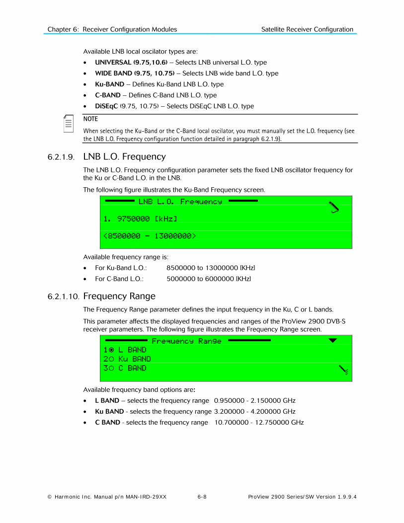
Chapter 6: Receiver Configuration Modules Satellite Receiver Configuration
© Harmonic Inc. Manual p/n MAN-IRD-29XX 6-8 ProView 2900 Series/SW Version 1.9.9.4
Available LNB local oscilator types are:
• UNIVERSAL (9.75,10.6) – Selects LNB universal L.O. type
• WIDE BAND (9.75, 10.75) – Selects LNB wide band L.O. type
• Ku-BAND – Defines Ku-Band LNB L.O. type
• C-BAND – Defines C-Band LNB L.O. type
• DiSEqC (9.75, 10.75) – Selects DiSEqC LNB L.O. type
NOTE
When selecting the Ku-Band or the C-Band local oscilator, you must manually set the L.O. frequency (see the LNB L.O. Frequency configuration function detailed in paragraph 6.2.1.9).
6.2.1.9. LNB L.O. Frequency The LNB L.O. Frequency configuration parameter sets the fixed LNB oscillator frequency for the Ku or C-Band L.O. in the LNB.
The following figure illustrates the Ku-Band Frequency screen.
LNB L.O. Frequency
1. 9750000 [kHz]
<8500000 - 13000000>
Available frequency range is:
• For Ku-Band L.O.: 8500000 to 13000000 [KHz]
• For C-Band L.O.: 5000000 to 6000000 [KHz]
6.2.1.10. Frequency Range The Frequency Range parameter defines the input frequency in the Ku, C or L bands.
This parameter affects the displayed frequencies and ranges of the ProView 2900 DVB-S receiver parameters. The following figure illustrates the Frequency Range screen.
Frequency Range
1 L BAND
2 Ku BAND
3 C BAND
Available frequency band options are:
• L BAND – selects the frequency range 0.950000 - 2.150000 GHz
• Ku BAND - selects the frequency range 3.200000 - 4.200000 GHz
• C BAND - selects the frequency range 10.700000 - 12.750000 GHz

Chapter 6: Receiver Configuration Modules Satellite Receiver Configuration
© Harmonic Inc. Manual p/n MAN-IRD-29XX 6-9 ProView 2900 Series/SW Version 1.9.9.4
6.2.1.11. Frequency Scan The Frequency Scan configuration function sets scanning a selected frequency range if the stream's frequency is unknown. The symbol rate must be known and set in the ProView 2900. The ProView 2900 scans the frequency range, while seeking a valid DVB stream. Upon locating a valid DVB stream, the ProView 2900 marks the located frequency and service name. Results output either to the RS-232 port (terminal) or Telnet. The following screen displays the Frequency Scan screen
NOTE
The ProView 2900 scans only the L-band frequency range. Located frequencies are shown in L-Band and must be modified for the relevant frequency value if they are tuned to either C-band or Ku-band.
The following figure illustrates the Frequency Scan screen.
Frequency Scan
1 OFF
2 BAND
3 +/-6 [MHz]
The available options are:
• OFF – Frequency scan is disabled.
• BAND – Frequency scan is enabled. This mode allows scanning all bands.
• +/-6 [MHz] – Frequency scan is enabled. This mode allows scanning a selected frequency range if the stream's frequency is unknown. This feature is especially useful for low symbol rates signals (less then 10Msym/s). All reception parameters must be set, including symbol rate and frequency. When operating the scanning, the ProView 2900 searches for a valid signal within a range of 12MHz (configured frequency ±6MHz). The ProView 2900 locks on the first detected valid signal, and automatically sets the configured frequency accordingly.

Chapter 6: Receiver Configuration Modules Satellite Receiver Configuration
© Harmonic Inc. Manual p/n MAN-IRD-29XX 6-10 ProView 2900 Series/SW Version 1.9.9.4
6.2.2. DVB-S2 Receiver Configuration This section details the front panel menus that enable configuring the DVB-S2 receiver in a ProView 2900 DVB-S2 front end device. The following is the DVB-S2 Receiver configuration menu as displayed on the ProView 2900 front panel screen:
Receiver 1-2-1
01 Frequency 1.000000 [GHz]
02 Symbol Rate 27.000000 [Mbaud]
03 Modulation DVB-S2-N-QPSK
04 Roll-off 35%
05 Pilots ON
06 FEC Rate 8/9
07 Spectral Inversion AUTOMATIC
08 PL Scrambling Seed 000000
09 LNB Power Supply 18V (HORIZONTAL)
10 LNB 22 KHz OFF (Low Band)
11 Freq Drift Compensation OFF]
12 LNB L.O. Type C band
13 LNB L.O. Frequency 5150000
14 Frequency Range L BAND
15 Frequency Scan OFF
16 Acquisition Mode Timing
17 DVBS-MCLK 135[MHz]
Figure 6-3 displays the corresponding Web Management menu screen for the DVB-S2 Receiver Parameters.
NOTE
Sub-menus parameters may be vary from one model to another according to the ProView 2900 technical specifications and licensing.
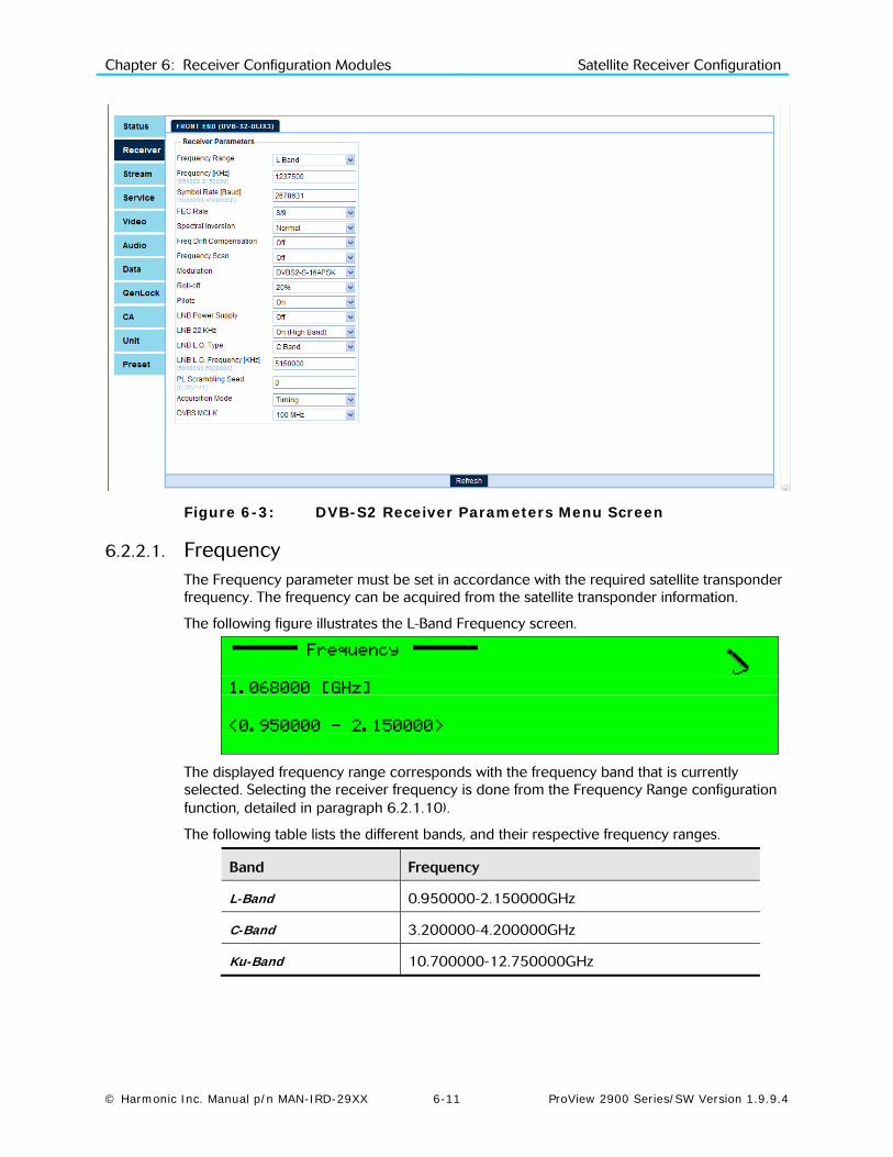
Chapter 6: Receiver Configuration Modules Satellite Receiver Configuration
© Harmonic Inc. Manual p/n MAN-IRD-29XX 6-11 ProView 2900 Series/SW Version 1.9.9.4
Figure 6-3: DVB-S2 Receiver Parameters Menu Screen
6.2.2.1. Frequency The Frequency parameter must be set in accordance with the required satellite transponder frequency. The frequency can be acquired from the satellite transponder information.
The following figure illustrates the L-Band Frequency screen.
Frequency
1.068000 [GHz]
<0.950000 - 2.150000>
The displayed frequency range corresponds with the frequency band that is currently selected. Selecting the receiver frequency is done from the Frequency Range configuration function, detailed in paragraph 6.2.1.10).
The following table lists the different bands, and their respective frequency ranges.
Band Frequency
L-Band 0.950000-2.150000GHz
C-Band 3.200000-4.200000GHz
Ku-Band 10.700000-12.750000GHz

Chapter 6: Receiver Configuration Modules Satellite Receiver Configuration
© Harmonic Inc. Manual p/n MAN-IRD-29XX 6-12 ProView 2900 Series/SW Version 1.9.9.4
6.2.2.2. Symbol Rate The Symbol Rate menu is used for adjusting the receiver’s symbol rate to the symbol rate of the received signal. The following figure illustrates the Symbol Rate screen.
Symbol Rate
27.000000 [Mbaud]
<00.016000 – 45.000000>
Available values range from 00.016000 to 45.000000 Mbaud
NOTE
The symbol rate must be set to match the exact symbol rate value used by the satellite transponder, down to the sixt digit after the decimal point (i.e, correct rate in bauds).
6.2.2.3. Modulation The Modulation menu allows setting the ProView 2900 receiver to the relevant modulation method. The following figure illustrates the Modulation screen.
Modulation
1 DVBS-QPSK
2 DVBS2-N-QPSK
3 DVBS2-N-8PSK
4 DVBS2-N-16PSK
5 DVBS2-S- QPSK
6 DVBS2-S-8APSK
7 DVBS2-S-16PSK
8 DVBS2-ACM
Available modulation options are:
• DVBS-QPSK
• DVBS2-N-QPSK, -8PSK, -16PSK
• DVBS2-S-QPSK, -8PSK,-16PSK
• DVBS2-ACM

Chapter 6: Receiver Configuration Modules Satellite Receiver Configuration
© Harmonic Inc. Manual p/n MAN-IRD-29XX 6-13 ProView 2900 Series/SW Version 1.9.9.4
6.2.2.4. Roll-Off The Roll-Off menu is used for setting the receiver’s roll-off factor value according to the roll-off factor of the transmitted signal.
The Roll-off factor is the factor that is used for the base-band shaping of the transmitted signal. Set the Roll-Off factor in accordance with the transmitted Roll-Off factor. The following figure illustrates the Roll-Off screen.
Roll-off
1 35%
2 25%
3 20%
Available options for the Roll-off factor are: 35%. 25%, 20%
6.2.2.5. Pilots In order to expedite carrier recovery, the standard allows two operating modes for each modulation type: Pilot-less (i.e. no Pilot symbols are inserted) and Piloted, where Pilot symbols are inserted to aid carrier synchronization. The Pilots menu enables to choose between the two operating modes. The following figure illustrates the Pilots screen.
Pilots
1 OFF
2 ON
The available options are:
• OFF – selects Pilot-less mode
• ON - selects Piloted mode
NOTE
The PLSCODE informs the receiver regarding the pilot configuration, which resides in the PLHEADER. Usually, only a few modes, such as 8PSK rate 2/3, 16APSK rate 2/3 and 3/4, and 32APSK rate 3/4, need pilot assistance for carrier recovery.

Chapter 6: Receiver Configuration Modules Satellite Receiver Configuration
© Harmonic Inc. Manual p/n MAN-IRD-29XX 6-14 ProView 2900 Series/SW Version 1.9.9.4
6.2.2.6. FEC Rate The FEC Rate menu enables to set the Forward Error Correction rate according to the FEC rate of the transmitted signal. The following figure illustrates the FEC Rate screen.
FEC Rate
01 1/4
02 1/3
03 2/5
04 1/2
05 3/5
06 2/3
07 3/4
08 4/5
09 5/6
10 7/8
11 8/9
12 9/10
The following table shows the available FEC rates for each module:
Module available FEC rates
DVB-S2, QPSK 1/4, 1/3, 2/5, 1/2, 3/5, 2/3, 3/4, 4/5, 5/6, 8/9, 9/10
DVB-S2, 8PSK 3/5, 2/3, 3/4, 5/6, 8/9, 9/10
DVB-S2, 16APSK 2/3, 3/4, 4/5, 5/6, 8/9, 9/10
6.2.2.7. Spectral Inversion The Spectral Inversion parameter sets the spectral mode of operation. This parameter is configured according to the information provided from the broadcast head-end or can be set to automatic. When set to automatic mode, the ProView 2900 tries the two spectral modes until obtaining synchronization.
The following figure illustrates the Spectral Inversion screen.
Spectral Inversion
1 AUTOMATIC
2 INVERTED
3 NORMAL
The available options are: AUTOMATIC, INVERTED or NORMAL spectral mode.

Chapter 6: Receiver Configuration Modules Satellite Receiver Configuration
© Harmonic Inc. Manual p/n MAN-IRD-29XX 6-15 ProView 2900 Series/SW Version 1.9.9.4
6.2.2.8. PL Scrambling Seed The Physical Layer (PL) Scrambling feature allows descrambling of the entire physical layer frame except its header part. The physical level scrambling is done according to a seed sequence that the user enters. The use of different PL Scrambling sequences allows a reduction of interference correlation between different services. For the same purpose, it is possible to reuse a shifted version of the same sequence in different satellite beams. Furthermore the seed can be associated to a satellite operator or transponder, thus permitting identification of an interfering signal via the PL Scrambling seed detection.
The PL Scrambling Seed screen allows setting the physical scrambling. The following figure illustrates the PL Scrambling Seed screen.
PL Scrambling Seed
+000000
<0 - +262141>
The PL Scrambling seed ranges from 0 to +262141.
6.2.2.9. LNB Power Supply The ProView 2900 sets the polarization of the receiving antenna by providing different voltage levels to the satellite Low Noise Block (LNB), 13v for vertical polarization and 18v for horizontal polarization. The polarization of the receiving antenna is determined according to the polarity of the satellite transponder.
The following figure illustrates the LBN Power Supply screen.
LNB Power Supply
1 13V (VERTICAL)
2 18V (HORIZONTAL)
3 OFF
The available options are:
• 13V (VERTICAL) – sets the LNB polarization to vertical.
• 18V (HORIZONTAL) - sets the LNB polarization to horizontal.
• OFF –power to the LNB is disabled.

Chapter 6: Receiver Configuration Modules Satellite Receiver Configuration
© Harmonic Inc. Manual p/n MAN-IRD-29XX 6-16 ProView 2900 Series/SW Version 1.9.9.4
6.2.2.10. LNB 22KHz The receiver controls the LNB band by sending a 22 kHz signal. When the signal is sent, the LNB uses its High Band Local Oscillator (L.O.). When the signal is not sent, the LNB uses its Low Band L.O.
The local oscillator is used to convert the signal from Ku-Band or C-Band to L-Band. Two local oscillators exist one for each band to leverage full spectrum. The following figure illustrates the LNB 22KHz screen.
LNB 22 KHz
1 OFF (Low Band)
2 ON (High Band)
The available options are:
• OFF (Low Band) – the 22 kHz signal is not generated and low band reception is selected.
• ON (High Band) - the 22 kHz signal is generated and high band reception is selected.
6.2.2.11. Freq Drift Compensation The ProView 29000 uses Freq Drift Compensation Feature to automatically correct inaccurate frequencies inserted by the operator.
When the operator sets the receiver frequency, the ProView 2900 checks whether the inserted frequency is set to the optimal frequency. When a deviation is detected, the ProView 2900 calculates the offset from the original setting and enables correcting it.
Turning on the Freq Drift Compensation in the following menu activates the automatic frequency adjustment. When Drift compensation is turned off, the device uses the original frequency setting that was inserted by the operator.
The following figure illustrates the Freq Drift Compensation screen.
Freq Drift Compensation
1 OFF
2 ON
The available options are:
• OFF – Drift Compensation is off; the receiver remains tuned to the configured frequency.
• ON - Drift Compensation is on; the receiver tunes to the optimum frequency.

Chapter 6: Receiver Configuration Modules Satellite Receiver Configuration
© Harmonic Inc. Manual p/n MAN-IRD-29XX 6-17 ProView 2900 Series/SW Version 1.9.9.4
6.2.2.12. LNB L.O. Type The LNB L.O. Type parameter defines the LNB oscillator type in use.
Two standards are generally used:
• LNB ‘Universal’ standard, in the 9.75 to 10.6 GHz, or the LNB Universal 'Wide Band’, in the 9.75 to 10.75 GHz range.
• Digital Sattelite Equipment Control (DiSEqC) standard, in the 9.75 to 10.6 GHz range.
In addition, the oscillator value can set to Ku Band or C Band and be manually configured (using the .
The following figure illustrates the LNB L.O. Type screen.
LNB L.O. Type
1 UNIVERSAL (9.75,10.6)
2 WIDE BAND (9.75,10.75)
3 Ku BAND
4 C BAND
5 DiSEqC (9.75, 10.6)
NOTEs
The LNB L.O. type can be acquired from satellite transponder information. Most satellites use the ‘Universal’ type of L.O. unless otherwise specified.
Manual configuration of the oscillator frequency is rarely used and is intended only for advanced users.
Available LNB local oscilator types are:
• UNIVERSAL (9.75,10.6) – Selects LNB universal L.O. type
• WIDE BAND (9.75, 10.75) – Selects LNB wide band L.O. type
• Ku-BAND – Defines Ku-Band LNB L.O. type
• C-BAND – Defines C-Band LNB L.O. type
• DiSEqC (9.75, 10.75) – Selects DiSEqC LNB L.O. type
NOTE
When selecting the Ku-Band or the C-Band local oscilator, you must manually set the L.O. frequency (see the LNB L.O. Frequency configuration function detailed in paragraph 6.2.1.9).

Chapter 6: Receiver Configuration Modules Satellite Receiver Configuration
© Harmonic Inc. Manual p/n MAN-IRD-29XX 6-18 ProView 2900 Series/SW Version 1.9.9.4
6.2.2.13. LNB L.O. Frequency The LNB L.O. Frequency configuration parameter sets the fixed LNB oscillator frequency for the Ku or C-Band L.O. in the LNB.
The following figure illustrates the Ku-Band Frequency screen.
LNB L.O. Frequency
1. 9750000 [kHz]
<8500000 - 13000000>
Available frequency range is:
• For Ku-Band L.O.: 8500000 to 13000000 [KHz]
• For C-Band L.O.: 5000000 to 6000000 [KHz]
6.2.2.14. Frequency Range The Frequency Range parameter defines the input frequency in the Ku, C or L bands.
This parameter affects the displayed frequencies and ranges of the ProView 2900 DVB-S2 receiver parameters. The following figure illustrates the Frequency Range screen.
Frequency Range
1 L BAND
2 Ku BAND
3 C BAND
Available frequency band options are:
• L BAND – selects the frequency range 0.950000 - 2.150000 GHz
• Ku BAND - selects the frequency range 3.200000 - 4.200000 GHz
• C BAND - selects the frequency range 10.700000 - 12.750000 GHz
6.2.2.15. Frequency Scan The Frequency Scan configuration function sets scanning a selected frequency range if the stream's frequency is unknown. The symbol rate must be known and set in the ProView 2900. The ProView 2900 scans the frequency range, while seeking a valid DVB stream. Upon locating a valid DVB stream, the ProView 2900 marks the located frequency and service name. Results output either to the RS-232 port (terminal) or Telnet. The following screen displays the Frequency Scan screen
NOTE
The ProView 2900 scans only the L-band frequency range. Located frequencies are shown in L-Band and must be modified for the relevant frequency value if they are tuned to either C-band or Ku-band.

Chapter 6: Receiver Configuration Modules Satellite Receiver Configuration
© Harmonic Inc. Manual p/n MAN-IRD-29XX 6-19 ProView 2900 Series/SW Version 1.9.9.4
The following figure illustrates the Frequency Scan screen.
Frequency Scan
1 OFF
2 BAND
3 +/-6 [MHz]
The available options are:
• OFF – Frequency scan is disabled.
• BAND – Frequency scan is enabled. This mode allows scanning all bands.
• +/-6 [MHz] – Frequency scan is enabled. This mode allows scanning a selected frequency range if the stream's frequency is unknown. This feature is especially useful for low symbol rates signals (less then 10Msym/s). All reception parameters must be set, including symbol rate and frequency. When operating the scanning, the ProView 2900 searches for a valid signal within a range of 12MHz (configured frequency ±6MHz). The ProView 2900 locks on the first detected valid signal, and automatically sets the configured frequency accordingly.
6.2.2.16. Acquisition Mode The Acquisition Mode scanning function sets the acquisition mode for the LNB local oscillator type; Range or Timing.
The following figure illustrates the Frequency Scan screen.
Acquisition Mode
1 Range
2 Timing
The available options are: Range and Timing.
• Range High acquisition range mode is used mainly for wide symbol rates usually in full transponder applications. In this mode the auto search range is -15% - +15% of the Symbol Rate.
• Timing Low acquisition range is used mainly for high sensitivity in order to receive signals with low power. This mode is used mainly for DSNG applications. In this mode the auto search range is -8% - +8% of the Symbol Rate.
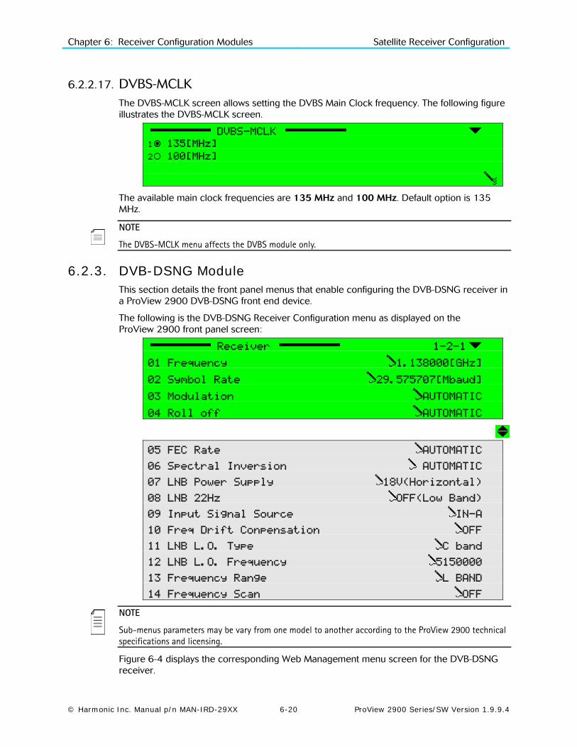
Chapter 6: Receiver Configuration Modules Satellite Receiver Configuration
© Harmonic Inc. Manual p/n MAN-IRD-29XX 6-20 ProView 2900 Series/SW Version 1.9.9.4
6.2.2.17. DVBS-MCLK The DVBS-MCLK screen allows setting the DVBS Main Clock frequency. The following figure illustrates the DVBS-MCLK screen.
DVBS-MCLK
1 135[MHz]
2 100[MHz]
The available main clock frequencies are 135 MHz and 100 MHz. Default option is 135 MHz.
NOTE
The DVBS-MCLK menu affects the DVBS module only.
6.2.3. DVB-DSNG Module This section details the front panel menus that enable configuring the DVB-DSNG receiver in a ProView 2900 DVB-DSNG front end device.
The following is the DVB-DSNG Receiver Configuration menu as displayed on the ProView 2900 front panel screen:
Receiver 1-2-1
01 Frequency 1.138000[GHz]
02 Symbol Rate 29.575707[Mbaud]
03 Modulation AUTOMATIC
04 Roll off AUTOMATIC
05 FEC Rate AUTOMATIC
06 Spectral Inversion AUTOMATIC
07 LNB Power Supply 18V(Horizontal)
08 LNB 22Hz OFF(Low Band)
09 Input Signal Source IN-A
10 Freq Drift Conpensation OFF
11 LNB L.O. Type C band
12 LNB L.O. Frequency 5150000
13 Frequency Range L BAND
14 Frequency Scan OFF
NOTE
Sub-menus parameters may be vary from one model to another according to the ProView 2900 technical specifications and licensing.
Figure 6-4 displays the corresponding Web Management menu screen for the DVB-DSNG receiver.

Chapter 6: Receiver Configuration Modules Satellite Receiver Configuration
© Harmonic Inc. Manual p/n MAN-IRD-29XX 6-21 ProView 2900 Series/SW Version 1.9.9.4
Figure 6-4: DVB-DSNG Receiver Parameters Menu Screen
6.2.3.1. Frequency The Frequency parameter must be set in accordance with the required satellite transponder frequency. The frequency can be acquired from the satellite transponder information.
The following figure illustrates the L-Band Frequency screen.
Frequency
1.068000 [GHz]
<0.950000 - 2.150000>
The displayed frequency range corresponds with the frequency band that is currently selected. Selecting the receiver frequency is done from the Frequency Range configuration function, detailed in paragraph 6.2.1.10).
The following table lists the different bands, and their respective frequency ranges.
Band Frequency
L-Band 0.950000-2.150000GHz
C-Band 3.200000-4.200000GHz
Ku-Band 10.700000-12.750000GHz
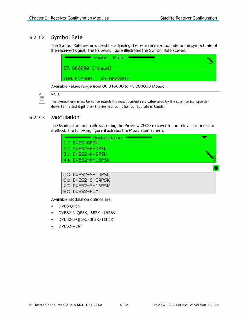
Chapter 6: Receiver Configuration Modules Satellite Receiver Configuration
© Harmonic Inc. Manual p/n MAN-IRD-29XX 6-22 ProView 2900 Series/SW Version 1.9.9.4
6.2.3.2. Symbol Rate The Symbol Rate menu is used for adjusting the receiver’s symbol rate to the symbol rate of the received signal. The following figure illustrates the Symbol Rate screen.
Symbol Rate
27.000000 [Mbaud]
<00.016000 – 45.000000>
Available values range from 00.016000 to 45.000000 Mbaud
NOTE
The symbol rate must be set to match the exact symbol rate value used by the satellite transponder, down to the sixt digit after the decimal point (i.e, correct rate in bauds).
6.2.3.3. Modulation The Modulation menu allows setting the ProView 2900 receiver to the relevant modulation method. The following figure illustrates the Modulation screen.
Modulation
1 DVBS-QPSK
2 DVBS2-N-QPSK
3 DVBS2-N-8PSK
4 DVBS2-N-16PSK
5 DVBS2-S- QPSK
6 DVBS2-S-8APSK
7 DVBS2-S-16PSK
8 DVBS2-ACM
Available modulation options are:
• DVBS-QPSK
• DVBS2-N-QPSK, -8PSK, -16PSK
• DVBS2-S-QPSK, -8PSK,-16PSK
• DVBS2-ACM

Chapter 6: Receiver Configuration Modules Satellite Receiver Configuration
© Harmonic Inc. Manual p/n MAN-IRD-29XX 6-23 ProView 2900 Series/SW Version 1.9.9.4
6.2.3.4. Roll-Off The Roll-Off menu is used for setting the receiver’s roll-off factor value according to the roll-off factor of the transmitted signal.
The Roll-off factor is the factor that is used for the base-band shaping of the transmitted signal. Set the Roll-Off factor in accordance with the transmitted Roll-Off factor. The following figure illustrates the Roll-Off screen.
Roll-off
1 35%
2 25%
3 20%
Available options for the Roll-off factor are: 35%. 25%, 20%
6.2.3.5. FEC Rate The FEC Rate parameter sets the Forward error correction rate value. The FEC parameter can be acquired from the satellite transponder information or can be set to automatic. When in Automatic mode, the ProView 2900 device tries all FEC rates until locking the rate to the transport stream.
FEC Rate
1 AUTOMATIC
2 1/2
3 2/3
4 3/4
5 5/6
6 7/8
6 8/9
The available options are: Automatic, 1/2, 2/3, 3/4, 5/6, 7/8, 8/9
NOTE
If the specific Viterbi rate is not provided, selecting the Automatic option enables the ProView 2900 to automatically detect the Viterbi rate.
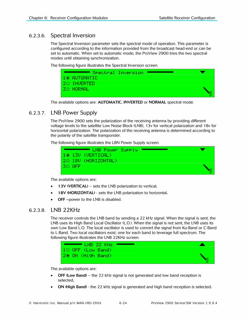
Chapter 6: Receiver Configuration Modules Satellite Receiver Configuration
© Harmonic Inc. Manual p/n MAN-IRD-29XX 6-24 ProView 2900 Series/SW Version 1.9.9.4
6.2.3.6. Spectral Inversion The Spectral Inversion parameter sets the spectral mode of operation. This parameter is configured according to the information provided from the broadcast head-end or can be set to automatic. When set to automatic mode, the ProView 2900 tries the two spectral modes until obtaining synchronization.
The following figure illustrates the Spectral Inversion screen.
Spectral Inversion
1 AUTOMATIC
2 INVERTED
3 NORMAL
The available options are: AUTOMATIC, INVERTED or NORMAL spectral mode.
6.2.3.7. LNB Power Supply The ProView 2900 sets the polarization of the receiving antenna by providing different voltage levels to the satellite Low Noise Block (LNB), 13v for vertical polarization and 18v for horizontal polarization. The polarization of the receiving antenna is determined according to the polarity of the satellite transponder.
The following figure illustrates the LBN Power Supply screen.
LNB Power Supply
1 13V (VERTICAL)
2 18V (HORIZONTAL)
3 OFF
The available options are:
• 13V (VERTICAL) – sets the LNB polarization to vertical.
• 18V (HORIZONTAL) - sets the LNB polarization to horizontal.
• OFF –power to the LNB is disabled.
6.2.3.8. LNB 22KHz The receiver controls the LNB band by sending a 22 kHz signal. When the signal is sent, the LNB uses its High Band Local Oscillator (L.O.). When the signal is not sent, the LNB uses its own Low Band L.O. The local oscillator is used to convert the signal from Ku-Band or C-Band to L-Band. Two local oscillators exist; one for each band to leverage full spectrum. The following figure illustrates the LNB 22KHz screen.
LNB 22 KHz
1 OFF (Low Band)
2 ON (High Band)
The available options are:
• OFF (Low Band) – the 22 kHz signal is not generated and low band reception is selected.
• ON (High Band) - the 22 kHz signal is generated and high band reception is selected.
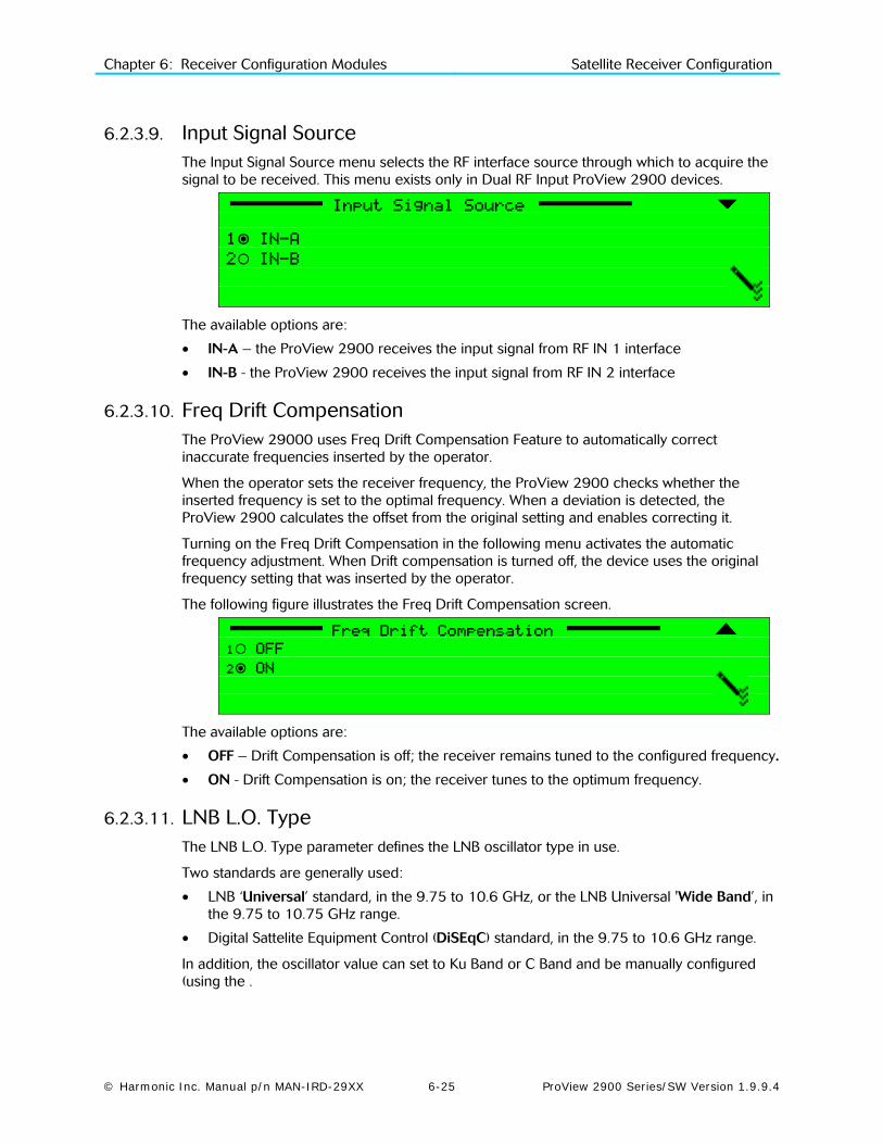
Chapter 6: Receiver Configuration Modules Satellite Receiver Configuration
© Harmonic Inc. Manual p/n MAN-IRD-29XX 6-25 ProView 2900 Series/SW Version 1.9.9.4
6.2.3.9. Input Signal Source The Input Signal Source menu selects the RF interface source through which to acquire the signal to be received. This menu exists only in Dual RF Input ProView 2900 devices.
Input Signal Source
1 IN-A
2 IN-B
The available options are:
• IN-A – the ProView 2900 receives the input signal from RF IN 1 interface
• IN-B - the ProView 2900 receives the input signal from RF IN 2 interface
6.2.3.10. Freq Drift Compensation The ProView 29000 uses Freq Drift Compensation Feature to automatically correct inaccurate frequencies inserted by the operator.
When the operator sets the receiver frequency, the ProView 2900 checks whether the inserted frequency is set to the optimal frequency. When a deviation is detected, the ProView 2900 calculates the offset from the original setting and enables correcting it.
Turning on the Freq Drift Compensation in the following menu activates the automatic frequency adjustment. When Drift compensation is turned off, the device uses the original frequency setting that was inserted by the operator.
The following figure illustrates the Freq Drift Compensation screen.
Freq Drift Compensation
1 OFF
2 ON
The available options are:
• OFF – Drift Compensation is off; the receiver remains tuned to the configured frequency.
• ON - Drift Compensation is on; the receiver tunes to the optimum frequency.
6.2.3.11. LNB L.O. Type The LNB L.O. Type parameter defines the LNB oscillator type in use.
Two standards are generally used:
• LNB ‘Universal’ standard, in the 9.75 to 10.6 GHz, or the LNB Universal 'Wide Band’, in the 9.75 to 10.75 GHz range.
• Digital Sattelite Equipment Control (DiSEqC) standard, in the 9.75 to 10.6 GHz range.
In addition, the oscillator value can set to Ku Band or C Band and be manually configured (using the .

Chapter 6: Receiver Configuration Modules Satellite Receiver Configuration
© Harmonic Inc. Manual p/n MAN-IRD-29XX 6-26 ProView 2900 Series/SW Version 1.9.9.4
The following figure illustrates the LNB L.O. Type screen.
LNB L.O. Type
1 UNIVERSAL (9.75,10.6)
2 WIDE BAND (9.75,10.75)
3 Ku BAND
4 C BAND
5 DiSEqC (9.75, 10.6)
NOTEs
The LNB L.O. type can be acquired from satellite transponder information. Most satellites use the ‘Universal’ type of L.O. unless otherwise specified.
Manual configuration of the oscillator frequency is rarely used and is intended only for advanced users.
Available LNB local oscilator types are:
• UNIVERSAL (9.75,10.6) – Selects LNB universal L.O. type
• WIDE BAND (9.75, 10.75) – Selects LNB wide band L.O. type
• Ku-BAND – Defines Ku-Band LNB L.O. type
• C-BAND – Defines C-Band LNB L.O. type
• DiSEqC (9.75, 10.75) – Selects DiSEqC LNB L.O. type
NOTE
When selecting the Ku-Band or the C-Band local oscilator, you must manually set the L.O. frequency (see the LNB L.O. Frequency configuration function detailed in paragraph 6.2.1.9).
6.2.3.12. LNB L.O. Frequency The LNB L.O. Frequency configuration parameter sets the fixed LNB oscillator frequency for the Ku or C-Band L.O. in the LNB.
The following figure illustrates the Ku-Band Frequency screen.
LNB L.O. Frequency
1. 9750000 [kHz]
<8500000 - 13000000>
Available frequency range is:
• For Ku-Band L.O.: 8500000 to 13000000 [KHz]
• For C-Band L.O.: 5000000 to 6000000 [KHz]

Chapter 6: Receiver Configuration Modules Satellite Receiver Configuration
© Harmonic Inc. Manual p/n MAN-IRD-29XX 6-27 ProView 2900 Series/SW Version 1.9.9.4
6.2.3.13. Frequency Range The Frequency Range parameter defines the input frequency in the Ku, C or L bands.
This parameter affects the displayed frequencies and ranges of the ProView 2900 DVB-S2 receiver parameters. The following figure illustrates the Frequency Range screen.
Frequency Range
1 L BAND
2 Ku BAND
3 C BAND
Available frequency band options are:
• L BAND – selects the frequency range 0.950000 - 2.150000 GHz
• Ku BAND - selects the frequency range 3.200000 - 4.200000 GHz
• C BAND - selects the frequency range 10.700000 - 12.750000 GHz
6.2.3.14. Frequency Scan The Frequency Scan configuration function sets scanning a selected frequency range if the stream's frequency is unknown. The symbol rate must be known and set in the ProView 2900. The ProView 2900 scans the frequency range, while seeking a valid DVB stream. Upon locating a valid DVB stream, the ProView 2900 marks the located frequency and service name. Results output either to the RS-232 port (terminal) or Telnet. The following screen displays the Frequency Scan screen
NOTE
The ProView 2900 scans only the L-band frequency range. Located frequencies are shown in L-Band and must be modified for the relevant frequency value if they are tuned to either C-band or Ku-band.
The following figure illustrates the Frequency Scan screen.
Frequency Scan
1 OFF
2 BAND
3 +/-6 [MHz]
The available options are:
• OFF – Frequency scan is disabled.
• BAND – Frequency scan is enabled. This mode allows scanning all bands.
• +/-6 [MHz] – Frequency scan is enabled. This mode allows scanning a selected frequency range if the stream's frequency is unknown. This feature is especially useful for low symbol rates signals (less then 10Msym/s). All reception parameters must be set, including symbol rate and frequency. When operating the scanning, the ProView 2900 searches for a valid signal within a range of 12MHz (configured frequency ±6MHz). The ProView 2900 locks on the first detected valid signal, and automatically sets the configured frequency accordingly.

Chapter 6: Receiver Configuration Modules IP Receiver Configuration
© Harmonic Inc. Manual p/n MAN-IRD-29XX 6-28 ProView 2900 Series/SW Version 1.9.9.4
6.3. IP Receiver Configuration This section details the ProView 2900 Front Panel and Web Manager menus that enable configuring the IP Receiver in a ProView 2900 IP Front End device.
Figure 6-5 illustrates the structure of the configuration tree menu for the IP receiver.
Figure 6-5: IP Receiver Configuration Menu Tree Structure

Chapter 6: Receiver Configuration Modules IP Receiver Configuration
© Harmonic Inc. Manual p/n MAN-IRD-29XX 6-29 ProView 2900 Series/SW Version 1.9.9.4
The following is the IP Receiver configuration menu as it is displayed on the ProView 2900 front panel screen:
Receiver 1-2-1
1 MPEGoIP Input 1
2 MPEGoIP Input 2
3 General
The available options are:
• MPEGoIP Input 1 - allows the user to configure the MPEGoIP receiver connected to the rear panel MPEGoIP IN 1 interface (for details, refer to paragraph 6.3.1).
• MPEGoIP Input 2- allows the user to configure the MPEGoIP receiver connected to the rear panel MPEGoIP IN 2 interface (for details, refer to paragraph 6.3.1).
• General allows the user to confugure parameters such as redundancy, De-jittering delay, and FEC (for details, refer to paragraph 6.3.2)..
6.3.1. MPEGoIP Input 1 The MPEGo-IP Input 1 sub-menu allows the user to configure the MPEGoIP receiver connected to the rear panel MPEGoIP interface.
NOTE
MPEGoIP Input 2 menu is identical to the MPEGoIP Input 1 menu
MPEGoIP Input 1 1-2-1-1
1 Physical Link 2 Logical Source 3 FEC
Figure 6-6 displays the corresponding DVB-IP Receiver MPEGoIP 1 Parameters Menu (Web Management screen).

Chapter 6: Receiver Configuration Modules IP Receiver Configuration
© Harmonic Inc. Manual p/n MAN-IRD-29XX 6-30 ProView 2900 Series/SW Version 1.9.9.4
Figure 6-6: DVB-IP Receiver – MPEGoIP 1 Parameters Menu Screen
The available options are:
• Physical Link – for configuring this physical link parameters
• Logical Source (Socket) – for configuring the IP parameters of the TS source end-device (“logical port” parameters)
• FEC – for configuring the Forward Error Correction parameters.

Chapter 6: Receiver Configuration Modules IP Receiver Configuration
© Harmonic Inc. Manual p/n MAN-IRD-29XX 6-31 ProView 2900 Series/SW Version 1.9.9.4
6.3.1.1. Physical Link The physical Link menu is used for enabling the operation of the physical link (the MPEGoIP IN1 interface in this example), as well as for configuring its parameters.
Physical Link 1-2-1-1-1
01 Operation DISABLE
02 IP Address 010.006.000.196
03 Subnet Mask 255.255.255.000
04 Default Gateway 010.006.000.001
Available options are:
• Operation - for enabling or disabling this port
• IP Address – for setting this MPEGoIP input port’s IP address
• Subnet Mask - for setting this MPEGoIP input port’s Subnet Mask
• Default Gateway - for setting the default gateway address
NOTES
The operator must enter valid IP addresses before the ProView 2900 can operate. If one or more IP addresses are not entered correctly, the following message is desplayed: “Front-End Warning – IP Configuration Error”. This message remains until all IP addresses are entered correctly.
Both MPEGoIP input ports must use the same gateway.
6.3.1.2. Logical Source (socket) The Logical Source menu is used for configuring the connection with the end device (“logical port”).
Logical Source 1-2-1-1-2
01 IP Address Type MULTICAST
02 IP Multicast Address 224.010.010.010
03 UDP Destination Port 02000
The available options are:
• IP Address Type - for choosing between Multicast and Unicast address types
MULTICAST – for selecting Multicast IP address type. When selected, the IP Multicast address menu is displayed, which enables configuring the Multicast address. An IGMP Join request is sent for connecting with the IP Multicast address that was configured. The ProView 2900 filters the relevant transport stream with the configured Multicast IP address and UDP port.
UNICAST - for selecting Unicast IP address type. The ProView 2900 filters the relevant transport stream only by the configured UDP port.
• IP Multicast Address - for setting the logical port’s IP address (this menu is displayed only when Multicast IP address type is selected)
• UDP Destination Port – for setting the logical port’s UDP port from which to receive data

Chapter 6: Receiver Configuration Modules IP Receiver Configuration
© Harmonic Inc. Manual p/n MAN-IRD-29XX 6-32 ProView 2900 Series/SW Version 1.9.9.4
6.3.1.3. FEC (Forward Error Correction) The ProView 2900 IP Front End-FEC Implementation complies with ProMPEG CoP3v2, with the following limitations:
Columns support only
Maximum TS bit-rate - 20 Mbps
FEC 1-2-1-1-3
1 FEC Column Port 02002
Selecting FEC Column Port displays the following screen, which allows setting the UDP port number carrying the FEC data.
FEC Column Port
02002
< 00000 – 65535 >
Available values range from 0 to 65535.
NOTE
The default FEC Column port is set to N+2, where N is the value of the UDP Destination port.
6.3.2. General The IP Receiver General Configuration screen allows the user to set several parameters:
General 1-2-1-3
1 Selected Active Port 01
2 Redundancy DISABLE
3 Redundancy Delay 005 [Sec]
4 De-Jitter Delay 0100 [mSec]
5 FEC DISABLE
Figure 6-7 displays the corresponding DVB-IP Receiver General Parameters Menu (Web Management screen).
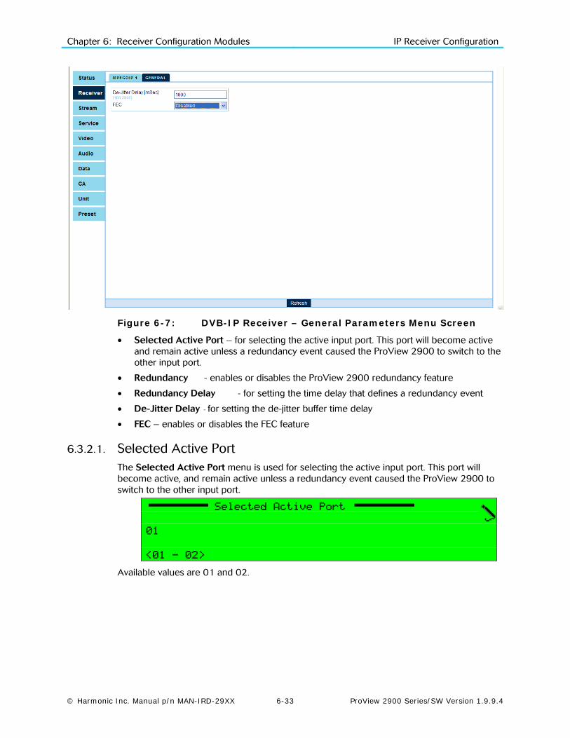
Chapter 6: Receiver Configuration Modules IP Receiver Configuration
© Harmonic Inc. Manual p/n MAN-IRD-29XX 6-33 ProView 2900 Series/SW Version 1.9.9.4
Figure 6-7: DVB-IP Receiver – General Parameters Menu Screen
• Selected Active Port – for selecting the active input port. This port will become active and remain active unless a redundancy event caused the ProView 2900 to switch to the other input port.
• Redundancy - enables or disables the ProView 2900 redundancy feature
• Redundancy Delay - for setting the time delay that defines a redundancy event
• De-Jitter Delay - for setting the de-jitter buffer time delay
• FEC – enables or disables the FEC feature
6.3.2.1. Selected Active Port The Selected Active Port menu is used for selecting the active input port. This port will become active, and remain active unless a redundancy event caused the ProView 2900 to switch to the other input port.
Selected Active Port
01
<01 - 02>
Available values are 01 and 02.

Chapter 6: Receiver Configuration Modules IP Receiver Configuration
© Harmonic Inc. Manual p/n MAN-IRD-29XX 6-34 ProView 2900 Series/SW Version 1.9.9.4
6.3.2.2. Redundancy The ProView 2900 IP front end supports both physical link and logical source redundancy. The physical link and logical source are coupled, i.e. switching from one physical link to the other (in the case of a link redundancy event) forces switching from the corresponding logical source to the other. In the case of a logical source redundancy event, the physical links are switched as well.
• Link Redundancy: protects the directly connected switch/router and the physical cable connection. There are two IP physical links to the ProView 2900: MPEGoIP IN1 and .MPEGoIP IN2.
• Source Redundancy: protects the transport stream source (encoder/streamer). Two logical sources (i.e. sockets), containing identical streams, must be configured to enable Source redundancy.
6.3.2.3. Redundancy Event A redundancy event causes the ProView 2900 to switch from the active Physical Link and Logical Source to the passive ones.
The device identifies a redundancy event when all the following conditions apply:
• Redundancy mode is enabled
• Active physical link failure (through PHY indication) or active logical source failure detection (no stream is being received for a preconfigured Redundancy Delay time [see next page)
• Passive physical link is configured, up, and connected
• Passive logical source is configured and connected
The following menu is used for enabling or disabling the operation of the redundancy feature.
Redundancy
1 ENABLE
2 DISABLE
The available options are:
• ENABLE – enables redundancy; when a redundancy event occurs the physical link and logical source switch to passive ones
• DISABLE - disables redundancy
6.3.2.4. Redundancy Delay The Redundancy delay menu is used for setting the time delay, which defines a redundancy event.

Chapter 6: Receiver Configuration Modules IP Receiver Configuration
© Harmonic Inc. Manual p/n MAN-IRD-29XX 6-35 ProView 2900 Series/SW Version 1.9.9.4
Redundancy Delay
005 [Sec]
<000 - 255>
Redundancy delay values range from 0 to 255 seconds.
6.3.2.5. De-Jitter Delay The De-jitter Delay menu is used for setting the decoder’s De-Jitter delay in milliseconds.
The aim of the De-Jittering mechanism is to eliminate the inherent jitter introduced by a typical IP network. This mechanism practically acquires the source exact frequency and follows it. The ProView 2900 supports de-jittering of CBR (Constant Bit Rate) streams.
The de-jitter delay configurability enables only optimizing unit-performance according to specific needs. The longer the delay, the longer the jitter that can be eliminated (traded off by longer latency).
De-Jitter Delay
0100 [mSec]
<100 - 2000>
De-jitter delay values range from 100 to 2000 milliseconds.
6.3.2.6. FEC The ProView 2900 IP Front End FEC Implementation complies with ProMPEG CoP3v2, with the following limitations:
Columns support only
Maximum TS bit-rate: 25 Mbps
This menu enables OR disables FEC operation.
FEC
1 ENABLE
2 DISABLE
The available options are:
• ENABLE – enables FEC operation; regenerates missing IP packets using FEC packets received from the configured UDP port.
• DISABLE - disables FEC operation; ignores FEC packets and does not regenerate missing IP packets.

Chapter 6: Receiver Configuration Modules DVB-ATM Receiver Configuration
© Harmonic Inc. Manual p/n MAN-IRD-29XX 6-36 ProView 2900 Series/SW Version 1.9.9.4
6.4. DVB-ATM Receiver Configuration This section details the ProView 2900 Front Panel and Web Manager menus that enable configuring the DVB-ATM receiver in a ProView 2900 DVB-ATM front end device.
The following is the DVB-ATM Receiver Configuration menu as displayed on the ProView 2900 front panel screen:
General 1-2-1
1 Mode DS3
2 VPI Address 01
2 VCI Address 0020
4 FEC ENABLE
The available options are:
• Mode – this parameter allows the user to set the operational mode of the ATM receiver.
• VPI Address –this parameter allows the user to set the path address for the ATM receiver.
• VCI Address – this parameter allows the user to set the channel address for the ATM receiver.
• FEC – this parameter allows the user to enable FEC for the ATM receiver.
Figure 6-8 illustrates the structure of the configuration tree menu for the IP receiver.
Figure 6-8: DVB-ATM Receiver Configuration Menu Tree Structure

Chapter 6: Receiver Configuration Modules DVB-ATM Receiver Configuration
© Harmonic Inc. Manual p/n MAN-IRD-29XX 6-37 ProView 2900 Series/SW Version 1.9.9.4
6.4.1. Mode The Mode parameter allows the user to set the operational mode of the ATM
receiver. The following is the front panel Mode screen:
Mode
1 E3
2 DS3
2 STM-1 MULTI MODE
4 STM-1 SINGLE MODE
5 OC-3 MULTI MODE
6 OC-3 SINGLE MODE
6.4.2. VPI Address The VPI Address parameter allows the user to set the path address for the ATM receiver. The following is the front panel VPI Address screen:
VPI Address
01[Hex]
<00-FF>
The available values range from 00 to FF.
6.4.3. VCI Address The VCI Address parameter allows the user to set the channel address for the ATM receiver. The following is the front panel VCI Address screen:
VPI Address
0020[Hex]
<0000-FFFF>
The available values range from 00 to FF.
6.4.4. FEC The FEC parameter allows the user to enable or disable FEC for the ATM receiver. The following is the front panel FEC screen:
VPI Address
1 Enable
2 Disable

© Harmonic Inc. Manual p/n MAN-IRD-29XX 7-1 ProView 2900 Series/SW Version 1.9.9.4
Chapter 7 Stream Configuration
This chapter details the Transport Stream configuration functions provided to the ProView 2900 User.
7.1. Stream Configuration Menu Tree The Stream Configuration Menu Tree is organized differently in the ProView 2900 Front Panel and in the Web Manager. Yet, both provide access to all the stream related parameters.
The following sub-paragraphs describe the organisation and access tree of the Stream Configuration when using the ProView 2900 Front Panel (see paragraph 7.1.1) and when using the ProView 2900 Web Manager (see paragraph 7.1.2).
The following paragraphs provide detailed configuration and set-up information on each stream configuration parameter, and access instructions for both ProView 2900 Front Panel and Web Manager Tools.
7.1.1. Front Panel Stream Configuration Tree To access the Stream Configuration menu in the front panel control interface go to ConfigurationStream.
Stream 1-2-2
1 Input
2 Output
3 Clock
4 Filtering
The configuration of the stream parameters using the ProView 2900 Front Panel Stream Configuration menu consists of the following:
• Stream Input configuration, detailed in paragraph 7.2.
• Stream Output configuration, detailed in paragraph 7.3.
• Stream Clock syncronization, detailed in paragraph 7.4.
• Stream Filtering configuration, consisting of the following configuration groups: General Filtering parameters, detailed in paragraph 7.5.
Service Filtering parameters, detailed in paragraph 7.5.4.
PID Filtering parameters, detailed in paragraph 7.5.5.
Figure 7-1 displays the tree structure of the ProView 2900 Front Panel Stream Configuration Menu.

Chapter 7: Stream Configuration Menu Stream Configuration Menu Tree
© Harmonic Inc. Manual p/n MAN-IRD-29XX 7-2 ProView 2900 Series/SW Version 1.9.9.4
Figure 7-1: Front Panel Stream Configuration Menu Tree

Chapter 7: Stream Configuration Menu Stream Configuration Menu Tree
© Harmonic Inc. Manual p/n MAN-IRD-29XX 7-3 ProView 2900 Series/SW Version 1.9.9.4
7.1.2. Web Management Stream Configuration Tree To access the Stream Configuration menu in the Web Management control interface go to Stream Tab.
The configuration of the stream parameters using the ProView 2900 Web Manager Stream menu consists of the following:
• General configuration, consisting of the following configuration groups: Stream Input configuration, detailed in paragraph 7.2.
Stream Output configuration, detailed in paragraph 7.3.
Stream Clock syncronization, detailed in paragraph 7.4.
• Filtering parameters, detailed in paragraph 7.5.
• Select Services parameters, detailed in paragraph 7.5.4.
• Select PID parameters, detailed in paragraph 7.5.5.
Figure 7-2 displays the tree structure of the ProView 2900 Web Management Stream Configuration Menu.

Chapter 7: Stream Configuration Menu Stream Configuration Menu Tree
© Harmonic Inc. Manual p/n MAN-IRD-29XX 7-4 ProView 2900 Series/SW Version 1.9.9.4
Figure 7-2: Web Management Stream Configuration Menu Tree

Chapter 7: Stream Configuration Menu Stream Input
© Harmonic Inc. Manual p/n MAN-IRD-29XX 7-5 ProView 2900 Series/SW Version 1.9.9.4
7.2. Stream Input The ProView 2900 supports a wide range of optional input interfaces, allowing the ProView 2900 to receive input streams from different sources.
To access the Stream Input Configuration menu in the ProView 2900 Front Panel, go to ConfigurationStreamInput .
Input
1 Source
2 Type
3 Rate Range
4 Identifier (ISI) 00
05 ASI Mode Burst
The respective Web Management menu is provided in the StreamGeneralInput window.
The following options are provided in both interfaces.
• Source, selects the source input stream
• Type, selects between ATSC format and DVB format
• Rate Range, selects the rate range of the ASI input
• Identifier, sets the stream identifier byte for the selected encapsulated stream in a Multiple Input Streams received by the DVB-S2 front-end receiver.
• ASI Mode, selects the input mode for the stream received over the ASI input.

Chapter 7: Stream Configuration Menu Stream Input
© Harmonic Inc. Manual p/n MAN-IRD-29XX 7-6 ProView 2900 Series/SW Version 1.9.9.4
7.2.1. Source The Source parameter defines the input stream source.
When the receiver is active in the ProView 2900, the following menu is displayed:
Source
1 FRONT-END (QPSK)
2 ASI
3 SERIAL RS-422
4 None
The available options are:
• FRONT-END (if applicable) – Selects the Receiver Front-End Interface as the source for the input transport stream
• ASI – Select the ASI digital input as the source for the input transport stream
• SERIAL RS-422 – Selects the RS-422 serial input as the source for the input transport stream
• None - No input source is selected for the ProView 2900.
NOTES
The Decoder Stream Source screen is dynamic and it changes according to the currently-active ProView 2900 interface.
Only qualified personnel should handle serial RS-422 option.
When Front-End (IP) is selected, the 27 MHz Synchronization option must be set to Fixed-Value.
7.2.2. Type The Type parameter allows selecting between ATSC format and DVB format.
Type
1 ATSC
2 DVB

Chapter 7: Stream Configuration Menu Stream Input
© Harmonic Inc. Manual p/n MAN-IRD-29XX 7-7 ProView 2900 Series/SW Version 1.9.9.4
7.2.3. Rate Range The Rate Range parameter defines the range of the ASI input rates.
Rate Range
1 UPTO 72Mb/s
2 UPTO 108Mb/s
3 ABOVE 108Mb/s
The available options are:
• UPTO 72Mb/s – Selected when using a CAM for descrambling
• UPTO 108Mb/s – Selected when not using CAM and inputting a transport Stream within a rate of 72 to 108Mb/s.
• ABOVE 108Mb/s – Not in use.
NOTE
The ASI Input-Rate Range parameter in the front panel interface corresponds with Stream Rate Range in the Web management interface (see Figure 7-2).
7.2.4. Input Stream Identifier (ISI) The ProView 2900 support Multiple Input transport Streams (MIS). This support is being done using DVB-S2 Input Stream Identifier (ISI).
This identifier is present in the Baseband Header of a DVB-S2 Baseband Frame.
The ISI is a single byte identifying the encapsulated stream in case of Multiple Input Streams and by entering it the user can choose which TS to receive.
Identifier (ISI)
00[Hex]
<00-FF>
The Identifer ISI value ranges from 00[Hex] to FF[Hex].
7.2.5. ASI Mode The ASI Mode parameter allows selecting between BURST format and NORMAL format.
Type
1 BURST
2 NORMAL

Chapter 7: Stream Configuration Menu Stream Output
© Harmonic Inc. Manual p/n MAN-IRD-29XX 7-8 ProView 2900 Series/SW Version 1.9.9.4
7.3. Stream Output The ProView 2900 supports a wide range of optional output interfaces, allowing the ProView 2900 to send output streams to different destinations.
To access the Stream Output Configuration menu in the ProView 2900 Front Panel, go to ConfigurationStreamOutput .
Output
1 ASI Output Source
2 IP Output Source
The respective Web Management menu is provided in the StreamGeneralOutput window.
The following options are provided in both interfaces.
• ASI Output Source, which selects type of source for the ASI Output
• IP Output Source, which selects type of source for the IP Output
7.3.1. ASI Output Source The ASI Output Source parameter defines the type of ASI output source.
ASI Output Source
1 DECODER SOURCE
2 AFTER DECRYPTION
3 AFTER FILTERING
4 DISABLED
The available options are:
• DECODER SOURCE – Input stream is directly routed to the ASI output
• AFTER DECRYPTION – Stream passes the CAM and then is directed to the ASI output
• AFTER FILTERING – Stream passes the CAM and then is directed to the ASI output
• DISABLED – ASI output signal is disabled
7.3.2. IP Output Source The IP Output Source parameter defines the type of IP output source.
IP Output Source
1 NO FILTERING
2 AFTER FILTERING
3 DISABLED
The available options are:
• NO FILTERING – Input stream is directly routed to the IP Output
• AFTER FILTERING – Stream passes the CAM and then is directed to the IP Output
• DISABLED – IP output signal is disabled

Chapter 7: Stream Configuration Menu Clock
© Harmonic Inc. Manual p/n MAN-IRD-29XX 7-9 ProView 2900 Series/SW Version 1.9.9.4
7.4. Clock Defines the synchronization source for the ProView 2900.
To access the Stream Clock Configuration menu in the ProView 2900 Front Panel, go to ConfigurationStreamClock.
Clock
1 27MHz Synchronization
The 27 MHz Synchronization configuration option defines the synchronization source for the ProView 2900 VCXO.
The Decoder Synchronization Source is a 27 MHz clock, generated by a Voltage Controlled Crystal Oscillator (VCXO). It is used to synchronize the ProView 2900 to the MPEG stream.
27MHz Synchronization
1 STREAM PCR
2 FIXED VALUE
3 GENLOCK
4 GENLOCK (LipSync)
The respective Web Management menu is provided in the StreamGeneralClock window.
The available options are:
• STREM PCR – The VCXO is synchronized to the program clock recovered from the PCR data.
• FIXED VALUE – The VCXO is running in free mode.
• GENLOCK – Synchronizes the ProView 2900 according to MPEG Encoder external video signal.
• GENLOCK (LipSync) – Additional Genlock that Synchronizes the ProView 2900 according to the Video GenLock input. This feature ensures a range of approximately 4mSec delta time between Audio/Video synchronization.
NOTE
The VCXO is factory calibrated to a fixed 27 MHz clock.

Chapter 7: Stream Configuration Menu Stream Filtering Configuration
© Harmonic Inc. Manual p/n MAN-IRD-29XX 7-10 ProView 2900 Series/SW Version 1.9.9.4
7.5. Stream Filtering Configuration Stream Filtering is a licensing-required feature that allows the user to define a method for Service and PID filtering on streams delivered at the ProView 2900 ASI and IP output ports.
The following describes the filtering procedures, using both front panel and web-based management interfaces:
7.5.1. Filtering Using the Front Panel Interface To use filtering mode through the front panel perform the following:
1. Configure ASI and/or IP outputs to filtering mode (see section 7.3). To access the After Filtering submenus go to:
ConfigurationStreamOutputASI Output SourceAfter Filtering or
ConfigurationStreamOutputIP Output SourceAfter Filtering
2. Access the filtering menu by the following path:
RootConfigurationStreamFiltering
Filtering 1-2-2-4
1 General
2 Service
3 PID
3. Set the following General sub menu parameters: strategy, mode, Bit-rate mode and bit-rate. (see section 7.5.3). To access the General submenus go to: ConfigurationStream FilteringGeneral
4. In case that the service filtering strategy is selected, set the required services (see section 7.5.4). To access the Service submenus go to:
ConfigurationStream FilteringService
5. In case the PID filtering strategy is selected, set the required PIDs (see section 7.5.5). To access the General submenus go to:
ConfigurationStream FilteringPID
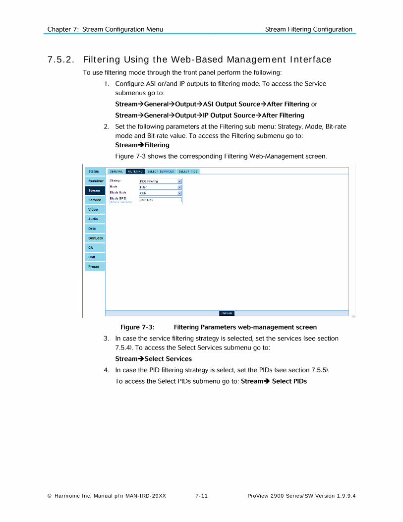
Chapter 7: Stream Configuration Menu Stream Filtering Configuration
© Harmonic Inc. Manual p/n MAN-IRD-29XX 7-11 ProView 2900 Series/SW Version 1.9.9.4
7.5.2. Filtering Using the Web-Based Management Interface To use filtering mode through the front panel perform the following:
1. Configure ASI or/and IP outputs to filtering mode. To access the Service submenus go to:
StreamGeneralOutputASI Output SourceAfter Filtering or
StreamGeneralOutputIP Output SourceAfter Filtering
2. Set the following parameters at the Filtering sub menu: Strategy, Mode, Bit-rate mode and Bit-rate value. To access the Filtering submenu go to: StreamFiltering
Figure 7-3 shows the corresponding Filtering Web-Management screen.
Figure 7-3: Filtering Parameters web-management screen
3. In case the service filtering strategy is selected, set the services (see section 7.5.4). To access the Select Services submenu go to:
StreamSelect Services
4. In case the PID filtering strategy is select, set the PIDs (see section 7.5.5).
To access the Select PIDs submenu go to: Stream Select PIDs

Chapter 7: Stream Configuration Menu Stream Filtering Configuration
© Harmonic Inc. Manual p/n MAN-IRD-29XX 7-12 ProView 2900 Series/SW Version 1.9.9.4
7.5.3. Filtering Parameters The Stream Filtering General menu provides several filtering parameters for ASI and IP output ports.
To access the General menu through the front panel go to:
ConfigurationStreamFilteringGeneral
General 1-2-2-4-1
1 Mode TRANSMIT
2 Strategy PID
3 Biterate Mode CBR
4 Bitrate 72.000000[Mbs}
To access the General menu through the Web Manager go to: StreamFiltering
Figure 7-4 displays the corresponding general filtering Web management screen.
Figure 7-4: General Filtering Parameters Menu Screen
7.5.3.1. Mode This parameter allows the user to set the selected services or PIDs to be transmitted or filtered at the output ports. Two values are available: ConfigurationStreamFilteringGeneralMode
The following figure shows the Mode front panel screen:
Mode 1-2-2-4
TRANSMIT
FILTER
The available options are:
• TRANSMIT – this mode forwards only selected services or PIDs to the output (Excluding unselected or unreferenced services or PIDs).
• FILTER - this mode excludes the selected services or PIDs from the output.

Chapter 7: Stream Configuration Menu Stream Filtering Configuration
© Harmonic Inc. Manual p/n MAN-IRD-29XX 7-13 ProView 2900 Series/SW Version 1.9.9.4
7.5.3.2. Strategy This parameter allows the user to select one of three filter strategies. To access the Strategy submenu, from the front panel go to: ConfigurationStreamFilteringGeneral Strategy. The following figure shows the Strategy front panel screen:
Strategy 1-2-2-4
DECODED ONLY
SERVICE
PID
The available strategies options are:
• Decode Only – selects the service set on TV1 (for details see section 8.2). All of the service' PIDs (Video, Audio and so on) are transmitted or filtered (based on Mode parameter) to the ASI and/or IP outputs.
• Services Filtering – This mode allows the user to select specific services from a list (under “select services”). These modes are dynamic, means that the ProView 2900 follows the services' tables and automatically adds or remove PIDs accordingly. The user can select two types of services: Referenced services – any service included in the PAT.
Unreferenced service – the user can add any other service ID. When the service is received
at the input, the ProView 2900 will forward (or filter) it accordingly. This mode is useful for
scenarios were the user want to select an unreferenced service or configures the unit before
the system is fully deployed.
• PIDs Filtering – allows the user to select specific PIDs, which are selected from a list (under “select PIDs”). This mode is Static, means that the ProView 2900 forwards or filters the selected PIDs and does not change it when PMT is changed. The user can select 3 types of PIDs: Constant PIDs – such as PAT, CAT and so on. the list is changed according to the stream type
DVB or ATSC which is configured by the user
Referenced PIDs – any PID which is included in the PMT of a referenced service.
Unreferenced PIDs – the user can add any other PID number. When the PID is received at the
input, the ProView 2900 will forward (or filter) it accordingly. This mode is useful for scenarios
were the user want to select an unreferenced PID or configures the unit before the system is
fully deployed.
7.5.3.3. Bitrate Mode This parameter defines the output stream as VBR or CBR. All NULL packets are removed at the input.
• VBR - allows variable output stream bit-rate. The ProView 2900 drops all unneeded services and PIDs according to the user selection. NULL packets are filtered at the input, and excluded from the output.
• CBR – allows constant output stream bit-rate; the bitrate is configured by the user. ProView 2900 drops all unneeded services and PIDs. NULL packets are dropped at the input; however, NULL packets are inserted at the output to meet the configured bit rate. The minimum configured bit rate should be 25 percents more then the selected services or PIDs accumulated maximum bit rate. This is due to momentarily burstiness scenario. In case that an overflow occurs, the "Filtering CBR Bit-rate is too Low" alarm is turned on (if the alarm is not masked, a trap is generated).
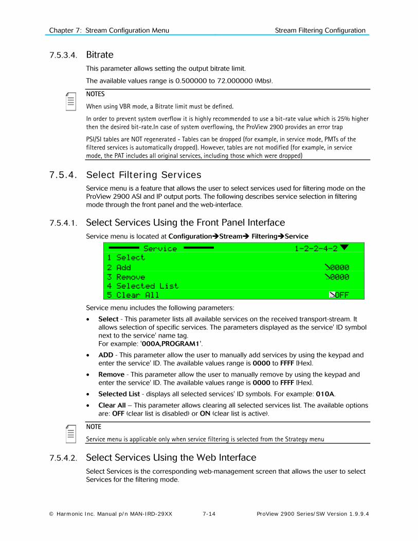
Chapter 7: Stream Configuration Menu Stream Filtering Configuration
© Harmonic Inc. Manual p/n MAN-IRD-29XX 7-14 ProView 2900 Series/SW Version 1.9.9.4
7.5.3.4. Bitrate This parameter allows setting the output bitrate limit.
The available values range is 0.500000 to 72.000000 (Mbs).
NOTES
When using VBR mode, a Bitrate limit must be defined.
In order to prevent system overflow it is highly recommended to use a bit-rate value which is 25% higher then the desired bit-rate.In case of system overflowing, the ProView 2900 provides an error trap
PSI/SI tables are NOT regenerated - Tables can be dropped (for example, in service mode, PMTs of the filtered services is automatically dropped). However, tables are not modified (for example, in service mode, the PAT includes all original services, including those which were dropped)
7.5.4. Select Filtering Services Service menu is a feature that allows the user to select services used for filtering mode on the ProView 2900 ASI and IP output ports. The following describes service selection in filtering mode through the front panel and the web-interface.
7.5.4.1. Select Services Using the Front Panel Interface Service menu is located at ConfigurationStream FilteringService
Service 1-2-2-4-2
1 Select
2 Add 0000
3 Remove 0000
4 Selected List
5 Clear All OFF
Service menu includes the following parameters:
• Select - This parameter lists all available services on the received transport-stream. It allows selection of specific services. The parameters displayed as the service' ID symbol next to the service' name tag. For example: '000A,PROGRAM1'.
• ADD - This parameter allow the user to manually add services by using the keypad and enter the service' ID. The available values range is 0000 to FFFF [Hex].
• Remove - This parameter allow the user to manually remove by using the keypad and enter the service' ID. The available values range is 0000 to FFFF [Hex].
• Selected List - displays all selected services' ID symbols. For example: 010A.
• Clear All – This parameter allows clearing all selected services list. The available options are: OFF (clear list is disabled) or ON (clear list is active).
NOTE
Service menu is applicable only when service filtering is selected from the Strategy menu
7.5.4.2. Select Services Using the Web Interface Select Services is the corresponding web-management screen that allows the user to select Services for the filtering mode.

Chapter 7: Stream Configuration Menu Stream Filtering Configuration
© Harmonic Inc. Manual p/n MAN-IRD-29XX 7-15 ProView 2900 Series/SW Version 1.9.9.4
Figure 7-5 displays the corresponding Select Services Parameters (Web Management screen).
Figure 7-5: Select Service Menu Screen
Select Services screen includes the following parameters:
• Referenced Services - This parameter lists all available services on the ProView 2900. It allows selection of specific service. The parameters displayed as the service' ID next to the service' name tag. In order to select a service, select the service' check box and click Submit.
• Unreferenced Services- This parameter lists all selected unreferenced services' IDs on the ProView 2900. The parameters displayed as the service' ID and name. It allows removal of an unreferenced service. In order to remove an unreferenced services, select the service' check box and click Submit.
NOTE
Unreferenced Services is unavailable when no unreferenced services have been selected
• Manual Service ID - This parameter allow the user to manually add service-to-filter by entering the service' ID in the text box and click on Submit.
• Clear - Clicking on Clear button empty all selected fields.
NOTE
Service menu is applicable only when service filtering is selected from Strategy menu

Chapter 7: Stream Configuration Menu Stream Filtering Configuration
© Harmonic Inc. Manual p/n MAN-IRD-29XX 7-16 ProView 2900 Series/SW Version 1.9.9.4
7.5.5. Select PIDs The PID menu screen is a feature that allows the user to select PIDs on the ProView 2900 ASI and IP output ports. The following describes PIDs selection in filtering mode through the front panel and the web-interface.
7.5.5.1. Select PIDs Using the Front Panel Interface PID menu is located at ConfigurationStream FilteringPID
PID 1-2-2-4-2
1 Select From Service
2 Add 0000
3 Remove 0000
4 Selected List
5 Clear All OFF
PID menu includes the following parameters:
• Select from Service - This table menu lists all available PIDs on the received transport-stream. It allows selection of specific PIDs from a service to be filtered. The select from service table menu consist of the following parameters:
• NAME – The service name
• ID – The service identification symbol [Hex]
• TYPE Service type options: TV, Radio, TLTX, NVOD, MOSAIC, PAL, SECAM, MAC, FM, NTSC, and Data.
• MODE – Indicates if the service is encrypted (CAS) or free to air (FTA).
For example: When selecting a Service listed at the Select from Service table menu, a list of all available PIDs of the selected services is displayed, and the user can select specific PIDs.
000A
1 SELECT ALL
2 REMOVE ALL
3 0100-PMT
4 0101-PCR The selected service's ID is displayed at the title. The first two parameters of every service list are:
• SELECT ALL – Select all PIDs of the current service. • REMOVE ALL – Remove all PID's of the current service.
The rest of the list includes available PIDs next to the PID' type.
ADD - This parameter allows the user to manually add PIDs by using the keypad and enter the
PID symbol [Hex]. The available values range is 0000 to 1FFF [Hex].
Remove - This parameter allows the user to manually remove PIDs from being filtered by
using the keypad and enter the PID symbol [Hex]. The available values range is 0000 to 1FFF
[Hex].
Selected List - This screen displays all selected PIDs, For example: 010A.
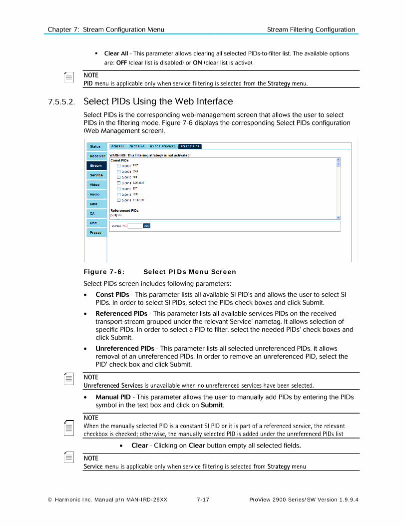
Chapter 7: Stream Configuration Menu Stream Filtering Configuration
© Harmonic Inc. Manual p/n MAN-IRD-29XX 7-17 ProView 2900 Series/SW Version 1.9.9.4
Clear All - This parameter allows clearing all selected PIDs-to-filter list. The available options
are: OFF (clear list is disabled) or ON (clear list is active).
NOTE PID menu is applicable only when service filtering is selected from the Strategy menu.
7.5.5.2. Select PIDs Using the Web Interface Select PIDs is the corresponding web-management screen that allows the user to select PIDs in the filtering mode. Figure 7-6 displays the corresponding Select PIDs configuration (Web Management screen).
Figure 7-6: Select PIDs Menu Screen
Select PIDs screen includes following parameters:
• Const PIDs - This parameter lists all available SI PID's and allows the user to select SI PIDs. In order to select SI PIDs, select the PIDs check boxes and click Submit.
• Referenced PIDs - This parameter lists all available services PIDs on the received transport-stream grouped under the relevant Service' nametag. It allows selection of specific PIDs. In order to select a PID to filter, select the needed PIDs' check boxes and click Submit.
• Unreferenced PIDs - This parameter lists all selected unreferenced PIDs. it allows removal of an unreferenced PIDs. In order to remove an unreferenced PID, select the PID' check box and click Submit.
NOTE Unreferenced Services is unavailable when no unreferenced services have been selected.
• Manual PID - This parameter allows the user to manually add PIDs by entering the PIDs symbol in the text box and click on Submit.
NOTE When the manually selected PID is a constant SI PID or it is part of a referenced service, the relevant checkbox is checked; otherwise, the manually selected PID is added under the unreferenced PIDs list
• Clear - Clicking on Clear button empty all selected fields.
NOTE Service menu is applicable only when service filtering is selected from Strategy menu

Chapter 7: Stream Configuration Menu Stream Filtering Configuration
© Harmonic Inc. Manual p/n MAN-IRD-29XX 7-18 ProView 2900 Series/SW Version 1.9.9.4
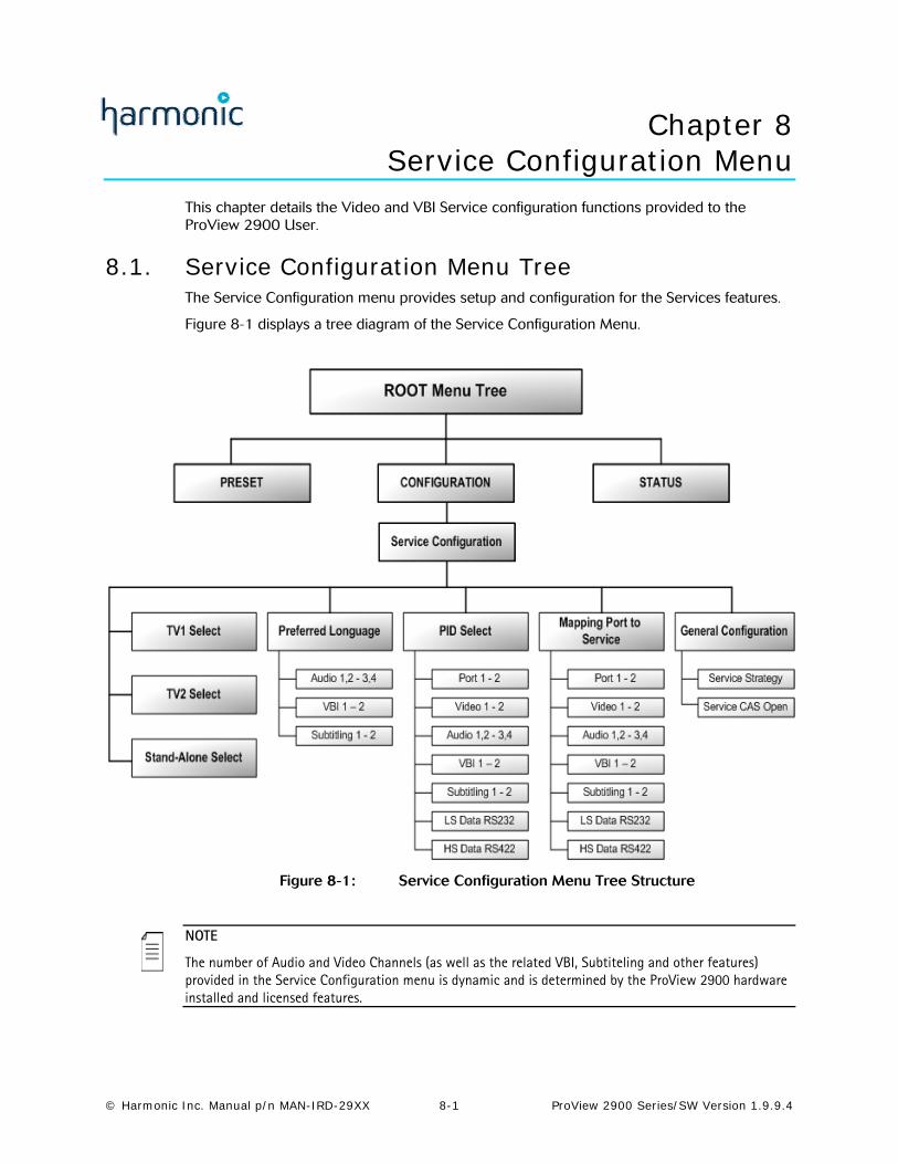
© Harmonic Inc. Manual p/n MAN-IRD-29XX 8-1 ProView 2900 Series/SW Version 1.9.9.4
Chapter 8 Service Configuration Menu
This chapter details the Video and VBI Service configuration functions provided to the ProView 2900 User.
8.1. Service Configuration Menu Tree The Service Configuration menu provides setup and configuration for the Services features.
Figure 8-1 displays a tree diagram of the Service Configuration Menu.
Figure 8-1: Service Configuration Menu Tree Structure
NOTE
The number of Audio and Video Channels (as well as the related VBI, Subtiteling and other features) provided in the Service Configuration menu is dynamic and is determined by the ProView 2900 hardware installed and licensed features.

Chapter 8: Service Configuration Menu Service Configuration Menu Tree
© Harmonic Inc. Manual p/n MAN-IRD-29XX 8-2 ProView 2900 Series/SW Version 1.9.9.4
To access the Service Configuration menu in the front panel control interface go to ConfigurationService.
The following screen displays the Service configuration menu from the ProView 2900 Front Panel:
Service 1-2-3
1 TV1 Select
2 TV2 Select
3 Stand-Alone Select
4 Preferred Language
5 PID Select
6 Mapping Port to Service
7 General Configuration+
Figure 8-2 displays the corresponding Service Configuration Menu structure in the ProView 2900 Web Management.
Figure 8-2: Web Manager Service Configuration Menu Screen
The Service Configuration menu provides access the the following parameters:
• TV1 (and TV2 Select, if applicable) Enables assign a service from the incoming TS to a decoder. In the case of a dual decoder, a user can assign two services from the incoming TS, one for each decoder (see Section 8.2).
• Stand-Alone Select This feature will be supported in the future software releases.
• Preferred Language This group contains parameters that define the preferred language (see Section 8.4).

Chapter 8: Service Configuration Menu TV1 Select (and TV2 Select)
© Harmonic Inc. Manual p/n MAN-IRD-29XX 8-3 ProView 2900 Series/SW Version 1.9.9.4
• PID Select This group contains parameters that define the PID components in the elementary stream (see Section 8.5).
• Mapping Port to Service This group contains parameters that define the port mapping and service components for each elementary stream (see Section 8.6).
• General Configuration This group contains parameters that define the response of the ProView 2900 to various operational modes (see Section 8.7).
8.2. TV1 Select (and TV2 Select) The TV1 Select screen lists the services analyzed from the service descriptor contained in the SDT.
NOTE
The TV2 Select Configuration function is available in dual decoder models of the ProView 2900 Series. It is identical to the TV1 Configuration menu.
The services in the TV1 Select and TV2 Select Configuration are displayed as a four-column table.
To access the TV1 Select (and TV2 Select) Table Menu in the front panel control interface go to ConfigurationServiceTV1 Select (or TV2 Select).
The following screen displays the TV1 Select (and TV2 Select) menu in the ProView 2900 Front Panel:
Name ID Type Mode
1 PROGRAM 1 000A TV FTA
2 PROGRAM 2 0046 TV FTA
3 PROGRAM 3 0050 TV CAS
4 PROGRAM 4 01F7 TV CAS
The table headers are as follows:
• NAME – The service name
• ID – The service identification symbol [Hex]
• TYPE Service type options: TV, Radio, TLTX, NVOD, MOSAIC, PAL, SECAM, MAC, FM, NTSC, and Data.
• MODE – Indicates if the service is encrypted (CAS) or free to air (FTA)
Selecting a service from the TV1 and TV2 Table displays the following Service Information table screen (relevant to the selected service):
TYPE PID Description Port
1 PCR 1262 PCR1
2 Video 1262 Video1
3 Audio 1273 English-eng AUDIO101
4 Vbi 1269 691.Swedish-swe VBI1

Chapter 8: Service Configuration Menu TV1 Select (and TV2 Select)
© Harmonic Inc. Manual p/n MAN-IRD-29XX 8-4 ProView 2900 Series/SW Version 1.9.9.4
Figure 8-3 displays the corresponding TV1 Menu in the Web Management.
Selecting a service in the Service roll-down window displays the service parameters in the Service Info window. Configuring the service PIDs is done from the PIDs window.
Figure 8-3: TV1 Menu Screen
The following sub-paragraphs details the configuration of the Service parameters, using the ProView 2900 Front Panel Service Configuration menu tree (ConfigurationServiceTV1 Select (or TV2 Select)[service name]).
Same parameters can be configured in the ProView 2900 Web Manager in the PIDs Window (ServiceTV1 Select (or TV2 Select)[service name]).
8.2.1. PCR The PCR elementary stream is a read only parameter.
8.2.2. Video The following figure displays the TV1 Video screen:
Video
1 None
2 Video1
The available options are:
• None – Video 1 (or Video 2 correspondingly) is not assigned to this Service.
• Video 1 (or Video 2) – Video 1 (or Video 2 correspondingly) is assigned to the Service.

Chapter 8: Service Configuration Menu TV1 Select (and TV2 Select)
© Harmonic Inc. Manual p/n MAN-IRD-29XX 8-5 ProView 2900 Series/SW Version 1.9.9.4
8.2.3. Audio The following figure displays the TV1 Audio screen:
Audio
1 None
2 Audio1
3 Audio2
The available options are:
• None – No Audio is assigned to this Service.
• Audio 1 (and Audio 3 correspondingly) – Audio 1 (or Audio 3 correspondingly) is assigned to the service.
• Audio 2 (and Audio 4 correspondingly) - Audio 2 (or Audio 4 correspondingly) is assigned to the service.
8.2.4. VBI The ProView 2900 Series supports decoding and displaying Teletext Subtitling graphics (according to DVB VBI standard EN 301 775, which specifies EBU Teletext subtitling data, used for language translation).
Differently from DVB subtitling, Teletext Subtitling requires the decoder to be able to create relevant language fonts. The ProView 2900 has the following Teletext Subtitling fonts installed:
• Croatian • Czech • Danish • Dutch • English • English Old • Estonian • Finnish
• French • German • Hungarian • Italian • Latvian • Lithuanian • Norwegian
• Portuguese • Romanian • Serbian • Slovak • Slovenian • Spanish • Swedish
Assigning a VBI to a Service through this menu allows adding Teletext Subtitles to the Service (for this purpose, the selected VBI PID must contain Teletext Subtitling data).
When choosing Teletext Subtitling here, the operator must also enable TLTX Subtitle Mode. For enabling TLTX Subtitle mode, see Section 9.4.
The following figure displays the TV1 VBI screen:
Vbi
1 None
2 VBi1
The available options are:
• None – This VBI PID is not assigned to the service.
• VBI 1 (and VBI 2 correspondingly) – VBI 1 (or VBI 2 correspondingly) is assigned to this service.
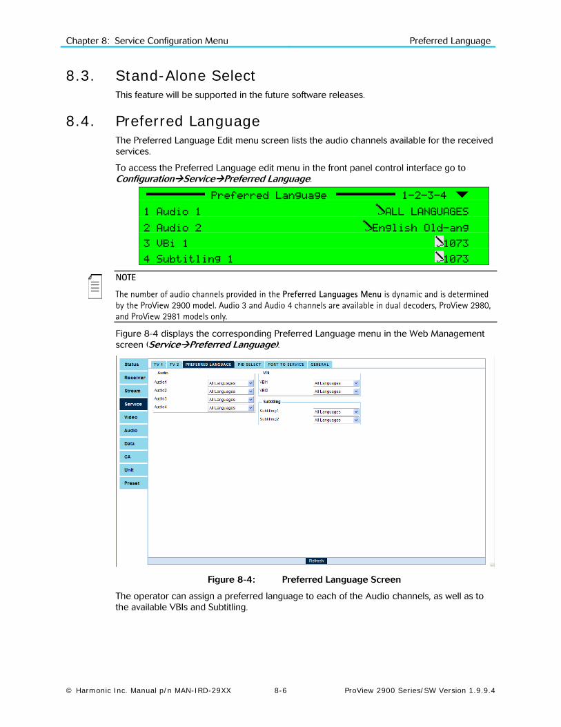
Chapter 8: Service Configuration Menu Preferred Language
© Harmonic Inc. Manual p/n MAN-IRD-29XX 8-6 ProView 2900 Series/SW Version 1.9.9.4
8.3. Stand-Alone Select This feature will be supported in the future software releases.
8.4. Preferred Language The Preferred Language Edit menu screen lists the audio channels available for the received services.
To access the Preferred Language edit menu in the front panel control interface go to ConfigurationServicePreferred Language.
Preferred Language 1-2-3-4
1 Audio 1 ALL LANGUAGES
2 Audio 2 English Old-ang
3 VBi 1 1073
4 Subtitling 1 1073
NOTE
The number of audio channels provided in the Preferred Languages Menu is dynamic and is determined by the ProView 2900 model. Audio 3 and Audio 4 channels are available in dual decoders, ProView 2980, and ProView 2981 models only.
Figure 8-4 displays the corresponding Preferred Language menu in the Web Management screen (ServicePreferred Language).
Figure 8-4: Preferred Language Screen
The operator can assign a preferred language to each of the Audio channels, as well as to the available VBIs and Subtitling.

Chapter 8: Service Configuration Menu PID Select
© Harmonic Inc. Manual p/n MAN-IRD-29XX 8-7 ProView 2900 Series/SW Version 1.9.9.4
Selecting option displays a Select Value screen that lists the following available languages:
01. ALL Languages
02. Albanian - alb
03. English Old - ang
04. Arabic - ara.
05. Armenian - arm.
06. Byelorussian - bel.
07. Bulgarian - bul.
08. Chechen - che
09. Chinese - chi
10. Check - cze
11. Danish - dan
12. German - deu
13. Dutch - dut
14. Egyptian - egy
15. English - eng
16. Spanish - esl
17. Finnish - fin
18. French - fra
19. French - fre
20. Gaelic - gae
21. German - ger
22. Greek Modern - gre
23. Hebrew - heb
24. Hindi - hin
25. Hungarian - hun
26. Indonesian - ind
27. Irish - iri
28. Italian - ita
29. Japanese - jpn
30. Latin - lat
31. Macedonian - mac
32. Miscellaneous - mis
33. Multiple - mul
34. Norvegian - nor
35. Turkish - ota
36. Persian - per
37. Polish - pol
38. Portuguese - por
39. Romany - rom
40. Romanian - ron
41. Russian - rus
42. Spanish - spa
43. Swedish - swe
44. Swedish - swe
45. Tamil -tam
46. Thai - tha
47. Zuylu - zul
Note
Option 01. ALL Languages (default). No specific language is selected. The audio language is set according to the Service PID.
8.5. PID Select The PID Select menu allows the operator to directly assign an ES to an output port directly, without attaching it to a Service. This option can be useful when the PMT is not available or is defective.
Before assigning the ES to an output, the operator verifies that the new PID entered is correct.
Caution
Using this control menu disassociates the selected elementry stream from any service and makes it a stand alone stream with no attached synchronization and no other associated signal. This may couse video and audio issues if not handle correctly.
This option is intended for advanced users only and should not be used normally. Create a Service only through ConfigurationServiceTV1/TV2 Select.
It is highly recommended to consult Harmonic Customer Support before using this control menu.
To access the PID Select Menu in the front panel control interface go to ConfigurationServicePID Select.

Chapter 8: Service Configuration Menu PID Select
© Harmonic Inc. Manual p/n MAN-IRD-29XX 8-8 ProView 2900 Series/SW Version 1.9.9.4
The following screen displays the PID Select menu:
PID Select 1-2-3-4
01 Pcr1 1062
03 Video1 1062
04 Audio 1 1073
05 Audio 2 101F
06 VBi 1 1064
07 Subtitling 1 1069
08 LS Data RS232 001F
09 HS Data RS-422 001F
Figure 8-5 displays the corresponding PID Select Menu in the Web Management screen.
Figure 8-5: PID Select Menu Screen
The available options are:
• PCR1, PCR2 (if applicable),
• Video1, Video2 (if applicable),
• Audio1, Audio2, Audio3 (if applicable), Audio4 (if applicable),
• VBI1, VBI2 (if applicable),
• Subtitling1, Subtitling2 (if applicable),
• LS Data RS-232, HS Data RS-422
All PID-Assigning screens are identical in structure and functionality. The only difference is the screen header, which changes according to the chosen port.
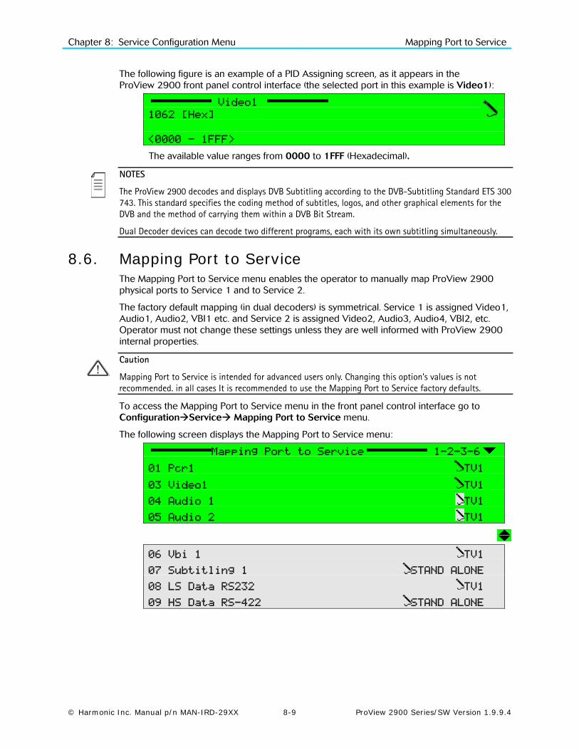
Chapter 8: Service Configuration Menu Mapping Port to Service
© Harmonic Inc. Manual p/n MAN-IRD-29XX 8-9 ProView 2900 Series/SW Version 1.9.9.4
The following figure is an example of a PID Assigning screen, as it appears in the ProView 2900 front panel control interface (the selected port in this example is Video1):
Video1
1062 [Hex]
<0000 - 1FFF>
The available value ranges from 0000 to 1FFF (Hexadecimal).
NOTES
The ProView 2900 decodes and displays DVB Subtitling according to the DVB-Subtitling Standard ETS 300 743. This standard specifies the coding method of subtitles, logos, and other graphical elements for the DVB and the method of carrying them within a DVB Bit Stream.
Dual Decoder devices can decode two different programs, each with its own subtitling simultaneously.
8.6. Mapping Port to Service The Mapping Port to Service menu enables the operator to manually map ProView 2900 physical ports to Service 1 and to Service 2.
The factory default mapping (in dual decoders) is symmetrical. Service 1 is assigned Video1, Audio1, Audio2, VBI1 etc. and Service 2 is assigned Video2, Audio3, Audio4, VBI2, etc. Operator must not change these settings unless they are well informed with ProView 2900 internal properties.
Caution
Mapping Port to Service is intended for advanced users only. Changing this option’s values is not recommended. in all cases It is recommended to use the Mapping Port to Service factory defaults.
To access the Mapping Port to Service menu in the front panel control interface go to ConfigurationService Mapping Port to Service menu.
The following screen displays the Mapping Port to Service menu:
Mapping Port to Service 1-2-3-6
01 Pcr1 TV1
03 Video1 TV1
04 Audio 1 TV1
05 Audio 2 TV1
06 Vbi 1 TV1
07 Subtitling 1 STAND ALONE
08 LS Data RS232 TV1
09 HS Data RS-422 STAND ALONE

Chapter 8: Service Configuration Menu Mapping Port to Service
© Harmonic Inc. Manual p/n MAN-IRD-29XX 8-10 ProView 2900 Series/SW Version 1.9.9.4
Figure 8-6 displays the corresponding Port to Service Menu (Web Management screen).
Figure 8-6: Port to Service Menu Screen
The available options are:
• PCR1, PCR2 (if applicable),
• Video1, Video2 (if applicable),
• Audio1, Audio2, Audio3 (if applicable), Audio4 (if applicable),
• VBI1, VBI2 (if applicable),
• Subtitling1, Subtitling2 (if applicable),
• LS Data RS232, HS Data RS-422
In order to map a port to service thru the front panel, perform the following:
Navigate to ConfigurationService Mapping Port to Service
Select one of the listed ports using the keypad. For example: PCR1.
After selection, the following menu screen lists all options for the selected port.
PCR1
1 STAND ALONE
2 TV1
3 TV2
The available options are:
• STAND ALONE – This mode indicates that you can assign the elementary stream PID. In this mode, the elementary stream is independent of the services selected for Decoder#1 and decoder#2.
• TV1 (and TV2, when available) – This mode indicates that the elementary stream is related to the service assigned to Decoder#1 (or Decoder#2 for TV2).

Chapter 8: Service Configuration Menu General Configuration
© Harmonic Inc. Manual p/n MAN-IRD-29XX 8-11 ProView 2900 Series/SW Version 1.9.9.4
8.7. General Configuration The Service General Configuration menu defines the ProView 2900 service selection strategy (either automatic or user-defined). It also allows the operator to instruct to the CAM (Conditional Access Module) which ES to decrypt.
To access the General Configuration menu, in the front panel control interface go to ConfigurationServiceGeneral Configuration.
The following is the front panel General Configuration screen:
General Configuration 1-2-3-7
1 Service Strategy AUTO. Call 1st'….
2 Service CAS Open DECODED PID’S….
Figure 8-7 displays the corresponding General Service menu (Web Management screen).
Figure 8-7: General Service Menu Screen
The General Configuration Parameters are:
• Service Strategy
• Service CAS Open
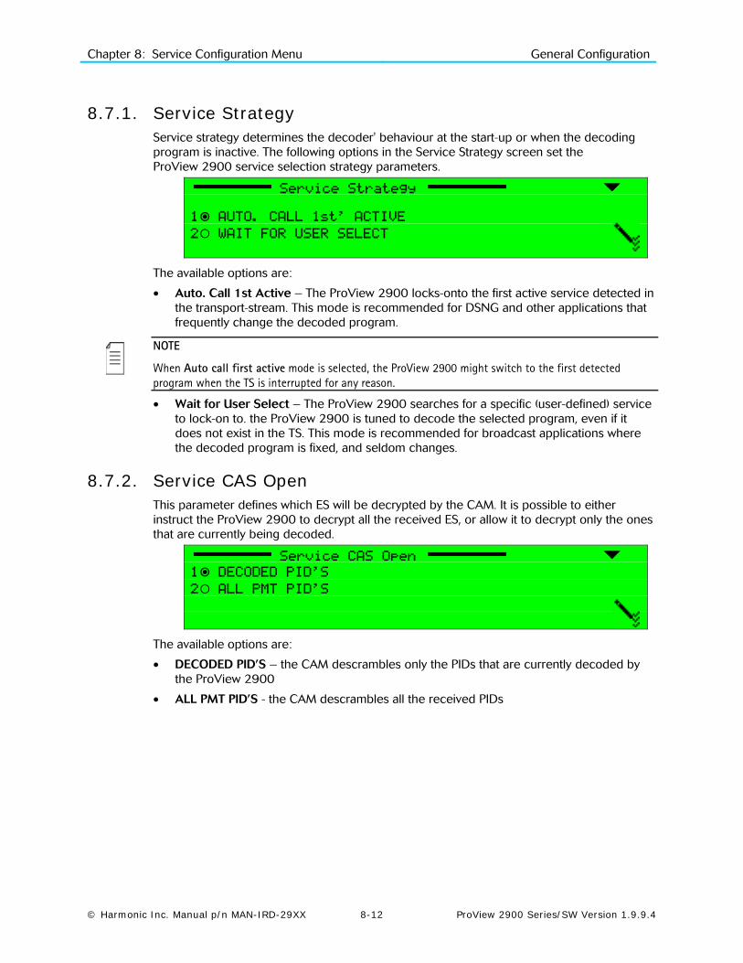
Chapter 8: Service Configuration Menu General Configuration
© Harmonic Inc. Manual p/n MAN-IRD-29XX 8-12 ProView 2900 Series/SW Version 1.9.9.4
8.7.1. Service Strategy Service strategy determines the decoder' behaviour at the start-up or when the decoding program is inactive. The following options in the Service Strategy screen set the ProView 2900 service selection strategy parameters.
Service Strategy
1 AUTO. CALL 1st’ ACTIVE
2 WAIT FOR USER SELECT
The available options are:
• Auto. Call 1st Active – The ProView 2900 locks-onto the first active service detected in the transport-stream. This mode is recommended for DSNG and other applications that frequently change the decoded program.
NOTE
When Auto call first active mode is selected, the ProView 2900 might switch to the first detected program when the TS is interrupted for any reason.
• Wait for User Select – The ProView 2900 searches for a specific (user-defined) service to lock-on to. the ProView 2900 is tuned to decode the selected program, even if it does not exist in the TS. This mode is recommended for broadcast applications where the decoded program is fixed, and seldom changes.
8.7.2. Service CAS Open This parameter defines which ES will be decrypted by the CAM. It is possible to either instruct the ProView 2900 to decrypt all the received ES, or allow it to decrypt only the ones that are currently being decoded.
Service CAS Open
1 DECODED PID’S
2 ALL PMT PID’S
The available options are:
• DECODED PID’S – the CAM descrambles only the PIDs that are currently decoded by the ProView 2900
• ALL PMT PID’S - the CAM descrambles all the received PIDs

© Harmonic Inc. Manual p/n MAN-IRD-29XX 9-1 ProView 2900 Series/SW Version 1.9.9.4
Chapter 9 Video Configuration Menu
This chapter details the Video configuration functions provided to the ProView 2900 User. The
9.1. Video Configuration Menu Tree Video Configuration menu contains parameters that set the video decoder mode of operation. Figure 9-1 displays the tree diagram of the Video Configuration Menu.
Figure 9-1: Video Configuration Menu Tree Structure
NOTE
The number of Video Channels (as well as the VBI and OSD functions) provided in the Video Configuration menu is dynamic and is determined by the ProView 2900 model hardware and licensed features (Video 2, VB I2 and OSD 2 requires dual decoder ProView 2900).

Chapter 9: Video Configuration Menu Video 1 (and Video 2) Configuration Options
© Harmonic Inc. Manual p/n MAN-IRD-29XX 9-2 ProView 2900 Series/SW Version 1.9.9.4
To access the Video Configuration menu in the front panel control interface go to ConfigurationVideo.
The following screen displays the Video menu:
Video 1-2-4
1 Video 1
2 VBI 1
3 Osd 1
4 Video 2
5 VBI 2
6 Osd 2
The Video Configuration parameters are as follows:
• Video 1 / Video 2 (if available) This group contains parameters that define the format, lip-sync mode and STC-PCR delay parameters for the video stream for a signal to decoder #1/#2. For details, see paragraph 9.2.
• VBI 1 / VBI 2 (if available) This group contains parameters that define VBI functioning for decoder #1/#2. For details, see paragraph 9.3.
• OSD 1 / OSD 2 (if available) This group contains parameters that define OSD functioning for decoder #1/#2. For details, see paragraph 9.4.
9.2. Video 1 (and Video 2) Configuration Options The Video 1 (and Video 2 in dual decoders ProView 2900) menu allow the user to set parameters for Video 1 and/or Video 2 outputs (if applicable).
To access Video 1 or Video 2 menu screens navigate to RootConfiguration VideoVideo 1 or Video2
The following section displays Video 1 configuration menu screens:
Video 1 1-2-4-1
1 Format PAL BG
2 Interpolation PAN-SCAN
3 Monitor Aspect-Ratio 4:3
4 Lip-sync Mode STANDARD LOCK
5 STC-PCR Delay 040 [mSec]
6 Blanking Mode Black
7 SDI Embedded Audio NULL
8 Test Mode NULL
Figure 9-2 displays the corresponding Video1 menu (Web Management screen).

Chapter 9: Video Configuration Menu Video 1 (and Video 2) Configuration Options
© Harmonic Inc. Manual p/n MAN-IRD-29XX 9-3 ProView 2900 Series/SW Version 1.9.9.4
Figure 9-2: Video Configuration Web Manager - Video 1 Menu Screen
NOTE
After selecting an option under the Video (1..2) menu, the front panel returns to the Video (1..2) menu and displays the current selection.
The following paragraphs detail Video Configuration options.
9.2.1. Format The Format parameter selects the format of the video signal. The following figure illustrates the Format screen.
Format
1 NTSC (SETUP ON)
2 NTSC (SETUP OFF)
3 PAL M
4 PAL BG
5 PAL D
6 PAL N
7 SECAM
8 RUSSIAN SECAM
The available options are: NTSC, PAL M, PAL BG, PAL D, PAL N, SECAM, RUSSIAN SECAM.

Chapter 9: Video Configuration Menu Video 1 (and Video 2) Configuration Options
© Harmonic Inc. Manual p/n MAN-IRD-29XX 9-4 ProView 2900 Series/SW Version 1.9.9.4
9.2.2. Interpolation The Interpolation parameter sets the re-sampling method of the image (should be set according to the Aspect Ratio parameter setting and to the actual aspect ratio of the received video signal)
NOTE
See Appendix C for extensive details on how Interpolation configuration affects the resulting image.
The following figure illustrates the Interpolation screen.
Interpolation
1 PAN-SCAN
2 LETTER-BOX
3 PASS-THRU
The available options are:
• PAN-SCAN – Set interpolation to Pan & Scan
• LETTER-BOX – Set interpolation to Letter-Box
• PASS-THRU – No interpolation occurs.
9.2.3. Monitor Aspect-Ratio This parameter sets the intended image aspect ratio. It is used along with Interpolation to determine the required Aspect Ratio Conversion.
NOTE
See Appendix C for extensive details on how Monitor Aspect-Ratio configuration affects the resulting image.
The following figure illustrates the Monitor Aspect-Ratio screen.
Monitor Aspect-Ratio
1 VIDEO Source
2 16:9
3 16:9 Box
4 4:3
5 14:9
6 14:9 Box
The available options are:
• VIDEO Source – Monitor aspect ratio is determined by the video sequence
• 16:9 – Monitor aspect ratio is set to 16:9.
• 16:9 Box – Monitor aspect ratio is set to 16:9 with letter-box.
• 4:3 – Monitor aspect ratio is set to 4:3.
• 14:9 – This option will be supported in future ProView 2900 versions.
• 14:9 Box – This option will be supported in future ProView 2900 versions.
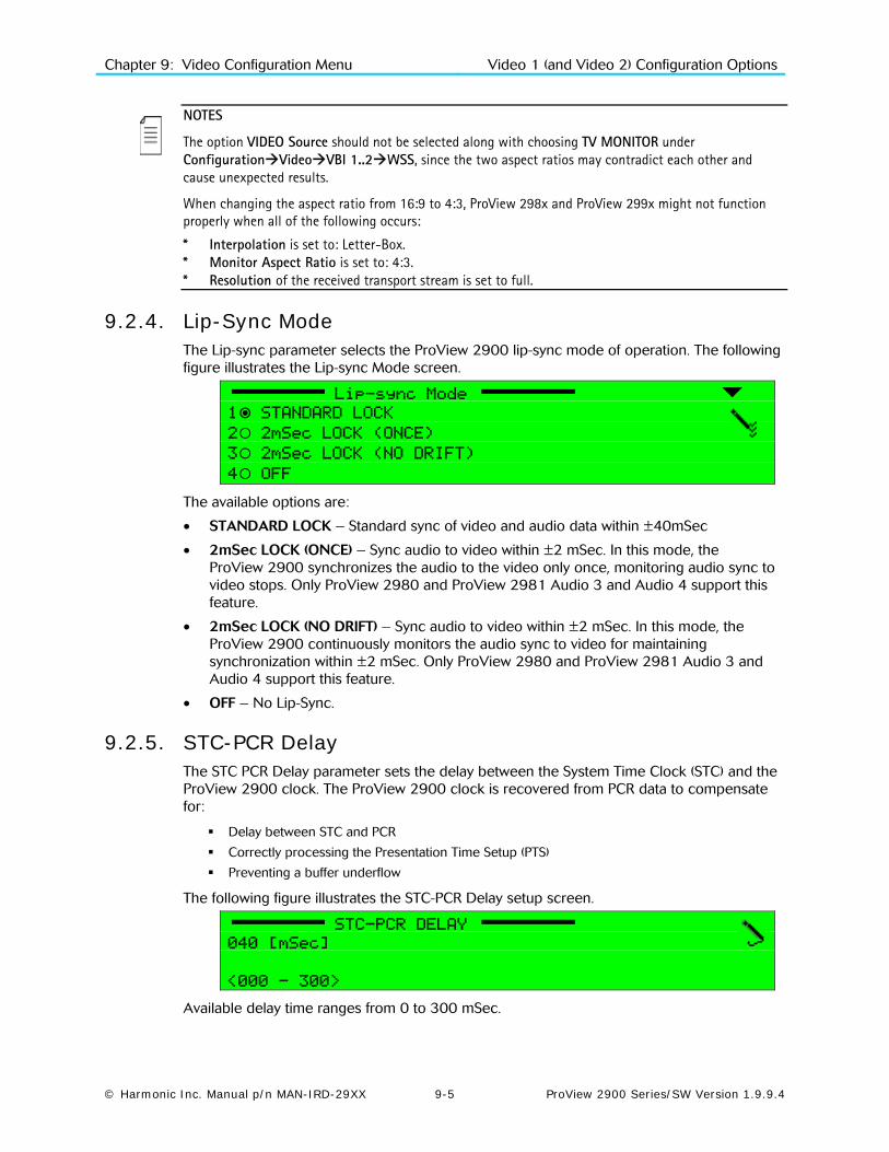
Chapter 9: Video Configuration Menu Video 1 (and Video 2) Configuration Options
© Harmonic Inc. Manual p/n MAN-IRD-29XX 9-5 ProView 2900 Series/SW Version 1.9.9.4
NOTES
The option VIDEO Source should not be selected along with choosing TV MONITOR under ConfigurationVideoVBI 1..2WSS, since the two aspect ratios may contradict each other and cause unexpected results.
When changing the aspect ratio from 16:9 to 4:3, ProView 298x and ProView 299x might not function properly when all of the following occurs:
* Interpolation is set to: Letter-Box. * Monitor Aspect Ratio is set to: 4:3. * Resolution of the received transport stream is set to full.
9.2.4. Lip-Sync Mode The Lip-sync parameter selects the ProView 2900 lip-sync mode of operation. The following figure illustrates the Lip-sync Mode screen.
Lip-sync Mode
1 STANDARD LOCK
2 2mSec LOCK (ONCE)
3 2mSec LOCK (NO DRIFT)
4 OFF
The available options are:
• STANDARD LOCK – Standard sync of video and audio data within ±40mSec
• 2mSec LOCK (ONCE) – Sync audio to video within ±2 mSec. In this mode, the ProView 2900 synchronizes the audio to the video only once, monitoring audio sync to video stops. Only ProView 2980 and ProView 2981 Audio 3 and Audio 4 support this feature.
• 2mSec LOCK (NO DRIFT) – Sync audio to video within ±2 mSec. In this mode, the ProView 2900 continuously monitors the audio sync to video for maintaining synchronization within ±2 mSec. Only ProView 2980 and ProView 2981 Audio 3 and Audio 4 support this feature.
• OFF – No Lip-Sync.
9.2.5. STC-PCR Delay The STC PCR Delay parameter sets the delay between the System Time Clock (STC) and the ProView 2900 clock. The ProView 2900 clock is recovered from PCR data to compensate for:
Delay between STC and PCR
Correctly processing the Presentation Time Setup (PTS)
Preventing a buffer underflow
The following figure illustrates the STC-PCR Delay setup screen.
STC-PCR DELAY
040 [mSec]
<000 - 300>
Available delay time ranges from 0 to 300 mSec.

Chapter 9: Video Configuration Menu Video 1 (and Video 2) Configuration Options
© Harmonic Inc. Manual p/n MAN-IRD-29XX 9-6 ProView 2900 Series/SW Version 1.9.9.4
NOTE
In the Web management interface, set the STC PCR Delay by typing the required delay (in Milliseconds) into the parameter’s free text window.
9.2.6. Blanking Mode The Blanking Mode parameter sets the display mode of a service when reception stops. The following figure illustrates the Blanking Mode screen.
Blanking Mode
1 Black
2 Last Field
3 Last Frame
4 75% BAR
5 Null
The available options are:
• Black – video output signal is a black screen.
• Last Field – video output signal is the last field displayed.
• Last Frame – video output signal is the last frame displayed.
• 75% BAR – video output signal is a colour-bar display.
• Null – video outputs shut down with no output signal.
9.2.7. SDI Embedded Audio The SDI Embedded Audio menu allows using SDI with embedded audio output.
The following figure illustrates the SDI Embedded Audio screen.
SDI Embedded Audio
1 DISABLE
2 ENABLE
The available options are:
• Disable – SDI output without embedded audio.
• Enable - SDI output with embedded audio
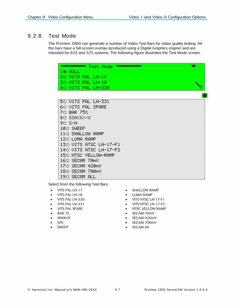
Chapter 9: Video Configuration Menu Video 1 (and Video 2) Configuration Options
© Harmonic Inc. Manual p/n MAN-IRD-29XX 9-7 ProView 2900 Series/SW Version 1.9.9.4
9.2.8. Test Mode The ProView 2900 can generate a number of Video Test Bars for video quality testing. All the bars have a full-screen overlay (produced using a Digital Graphics engine) and are intended for 625 and 525 systems. The following figure illustrates the Test Mode screen.
Test Mode
1 NULL
2 VITS PAL LN-17
3 VITS PAL LN-18
4 VITS PAL LN-330
5 VITS PAL LN-331
6 VITS PAL SPARE
7 BAR 75%
8 SIN(X)/X
9 S/N
10 SWEEP
11 SHALLOW RAMP
12 LUMA RAMP
13 VITS NTSC LN-17-F1
14 VITS NTSC LN-17-F2
15 NTSC YELLOW-RAMP
16 SECAM 70mV
17 SECAM 420mV
18 SECAM 700mV
19 SECAM ALL
Select from the following Test Bars:
• VITS PAL LN-17 • SHALLOW RAMP • VITS PAL LN-18 • LUMA RAMP • VITS PAL LN-330 • VITS NTSC LN-17-F1 • VITS PAL LN-331 • VITS NTSC LN-17-F2 • VITS PAL SPARE • NTSC YELLOW-RAMP • BAR 75 • SECAM 70mV • SIN(X)/X • SECAM 420mV • S/N • SECAM 700mV • SWEEP • SECAM All
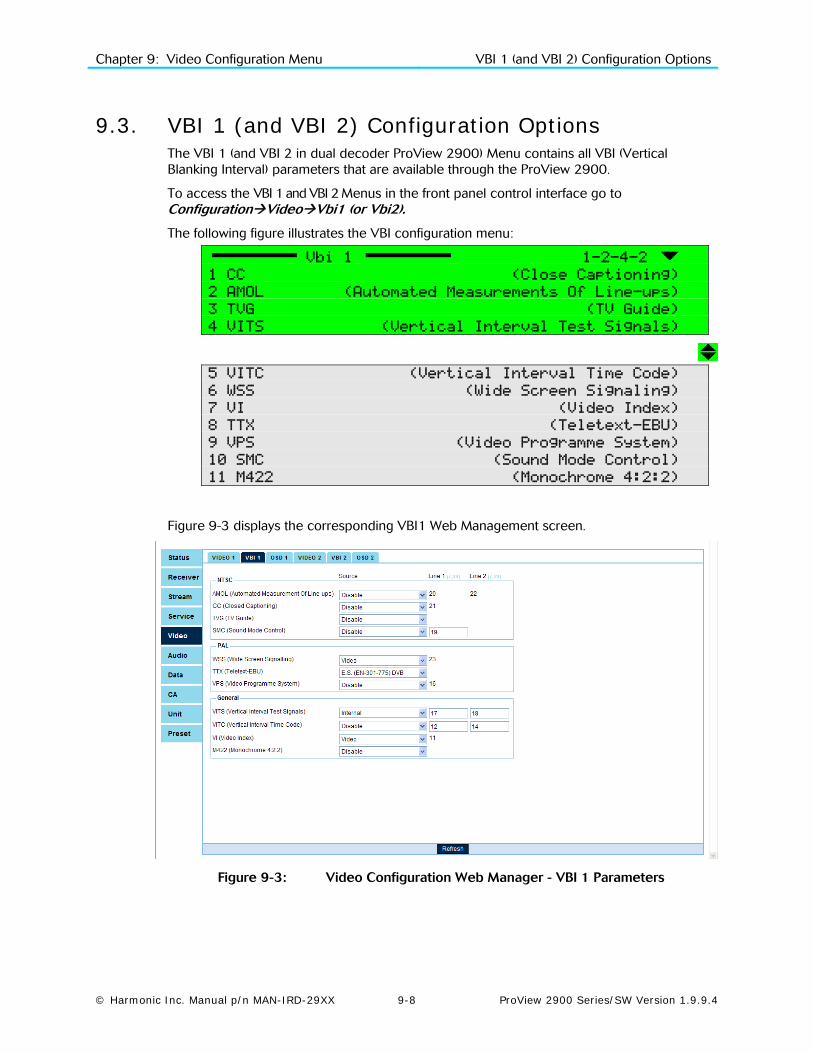
Chapter 9: Video Configuration Menu VBI 1 (and VBI 2) Configuration Options
© Harmonic Inc. Manual p/n MAN-IRD-29XX 9-8 ProView 2900 Series/SW Version 1.9.9.4
9.3. VBI 1 (and VBI 2) Configuration Options The VBI 1 (and VBI 2 in dual decoder ProView 2900) Menu contains all VBI (Vertical Blanking Interval) parameters that are available through the ProView 2900.
To access the VBI 1 and VBI 2 Menus in the front panel control interface go to ConfigurationVideoVbi1 (or Vbi2).
The following figure illustrates the VBI configuration menu:
Vbi 1 1-2-4-2
1 CC (Close Captioning)
2 AMOL (Automated Measurements Of Line-ups)
3 TVG (TV Guide)
4 VITS (Vertical Interval Test Signals)
5 VITC (Vertical Interval Time Code)
6 WSS (Wide Screen Signaling)
7 VI (Video Index)
8 TTX (Teletext-EBU)
9 VPS (Video Programme System)
10 SMC (Sound Mode Control)
11 M422 (Monochrome 4:2:2)
Figure 9-3 displays the corresponding VBI1 Web Management screen.
Figure 9-3: Video Configuration Web Manager - VBI 1 Parameters

Chapter 9: Video Configuration Menu VBI 1 (and VBI 2) Configuration Options
© Harmonic Inc. Manual p/n MAN-IRD-29XX 9-9 ProView 2900 Series/SW Version 1.9.9.4
The Web Manager provides configuration access to the same VBI parameters, arranged in three grops:
• NTSC Format related parameters, consisting of thefollowing: Automatic Measurement Of Lin-ups parameter (AMOL, see paragraph 9.3.2)
Close Capture parameter (CC, see paragraph 9.3.1)
TV Guide parameter (TVG, see paragraph 9.3.3)
Sound Mode Concept parameter (SMC, see paragraph 9.3.10)
• PAL Format related parameters, consisting of the following: Wide Screen Signalling parameter (WSS, see paragraph 9.3.6)
Teletex-EBU parameter (TTX, see paragraph 9.3.8)
Video Program System parameter (VPS, see paragraph 9.3.9).
• General parameters, related to both NTSC and PAL format, consisting of the following: Vertical Interval Time Signalling (VITS, see paragraph 9.3.4)
Vertical Interval Time Clock parameter (VITC, see paragraph 9.3.5)
Video Index parameter (VI, see paragraph 9.3.7)
Monochrome 4:2:2 parameter (M22, see paragraph 9.3.11)
The following paragraphs describe the VBI Configuration options.
9.3.1. CC (Closed Captioning) Parameter Selecting CC (Closed Captioning) displays the following screen:
CC 1-2-4-2-1
1 Source DISABLE
2 Line1 21
The CC screen parameters are:
• Source – used for selecting the source of closed captioning data
• Line1 - This is a read-only parameter (closed captioning data is automatically re-inserted in line 21).
Selecting Source option displays the following screen:
Source
1 DISABLE
2 E.S (EN-301-775)
3 VIDEO
4 VIDEO (ATSC A/53)
Available Closed Captioning sources are:
• DISABLE – CC is disabled.
• E.S (EN-301-775) – CC data is acquired according to the EN 301-775 DVB standard.
• VIDEO – The ProView 2900 automatically detects the existing CC standard and acquires the CC data accordingly.
• VIDEO (ATSC A/53) – The ProView 2900 automatically detects the existing CC standard and acquires the CC data accordingly, prioritizing the ATSC A/53 standard.

Chapter 9: Video Configuration Menu VBI 1 (and VBI 2) Configuration Options
© Harmonic Inc. Manual p/n MAN-IRD-29XX 9-10 ProView 2900 Series/SW Version 1.9.9.4
NOTE
The ProView 2900 supports the following CC standards:
* CCube standard * ATSC DVS-53 (Rev 57) EIA 608 * ATSC DVS-53 (Rev 57) caption type 4 * GI DVS-157
9.3.2. AMOL (Automatic Measurements Of Line-ups) Parameter Selecting AMOL displays the following screen:
AMOL 1-2-4-2-2
1 Source Disable
2 Line1 20
3 Line2 22
Selecting Source option displays the following screen:
Source
1 DISABLE
2 E.S (EN-301-775)
The available options are:
• DISABLE – AMOL is disabled.
• E.S (EN-301-775) – The ProView 2900 complies with the DVB EN 301-775 AMOL standard.
9.3.3. TVG (TV Guide) Parameter Selecting TVG (TV Guide) displays the following screen:
TVG (TV Guide) 1-2-4-2-3
1 Source DISABLE
Selecting Source option displays the following screen:
Source
1 DISABLE
2 E.S (EN-301-775)
The available options are:
• DISABLE – TV Guide reinsertion is disabled.
• E.S (EN-301-775) – TV Guide reinsertion is enabled according to the EN 301-775 standard

Chapter 9: Video Configuration Menu VBI 1 (and VBI 2) Configuration Options
© Harmonic Inc. Manual p/n MAN-IRD-29XX 9-11 ProView 2900 Series/SW Version 1.9.9.4
9.3.4. VITS (Vertical Interval Test Signals) Parameter The ProView 2900 supports 10 different VITS signals: 4 signals for PAL, 2 signals for NTSC and 4 signals for SECAM and Russian SECAM. The VITS signals are automatically selected according to the selected video format (PAL, TSC or SECAM/R.SECAM).
The PAL and NTSC VITS signals are according to ITU-T J.63 standard: PAL- Lines 17, 18, 330, 331 NTSC- Line 17 Field 1, Line 17 Field 2 SECAM/R.SECAM- Lines 17, 18, 330, 331
When working in PAL or SECAM/R.SECAM video format, the user can select two lines.
The factory setting is to Line 1: 17 and Line 2: 18. In this case, the ProView 2900 will re-insert the VITS signals automatically to lines 17, 18, 330, 331.
In the case of selecting different line numbers for VITS, the ProView 2900 calculates the new line numbers in which to re-insert the VITS signals. For example, changing Line 2 to 19 (instead of 18) will result in VITS signals re-inserted to lines: 17, 19, 330 and 332.
When the VBI Vertical Interval Test Signals (VITS) parameter is selected, the following screen is displayed:
VITS 1-2-4-2-4
1 Source INTERNAL
2 Line1 17
3 Line2 18
Selecting Source option displays the following screen:
Source
1 DISABLE
2 INTERNAL
The available options are:
• DISABLE – VITS is disabled.
• INTERNAL – The ProView 2900 inserts the VITS signal according to the ITU-T standard J. 63.
When selecting the Line 1 (or Line 2) option, the following screen is displayed:
Line1
17
<00 - 23>
NOTES
The VITS signal is inserted differently if using PAL or NTSC. When selecting PAL, VITS signals are inserted to lines 17 and 18 and to lines 330 and 331. When selecting NTSC, VITS signals are inserted to line 17-field 1 and line 17-field 2.

Chapter 9: Video Configuration Menu VBI 1 (and VBI 2) Configuration Options
© Harmonic Inc. Manual p/n MAN-IRD-29XX 9-12 ProView 2900 Series/SW Version 1.9.9.4
NOTES
The ProView 2900 enables the user to insert VITS signals to lines 17 and 18 as well as to any other line between 0 and 23.
In Russian SECAM format, there are special VITS signals, different in format from PAL VITS. The Russian SECAM VITS are inserted in lines 17 and 18 and in lines 330, and 331.
Only the ProView 2960, ProView 2961, and ProView 2990 support special Russian SECAM VITS.
9.3.5. VITC (Vertical Interval Time Code) Parameter When the Vertical Interval Time Code (VITC) VBI parameter is selected, the following screen is displayed:
VITC 1-2-4-2-5
1 Source DISABLE
2 Line1 12
3 Line2 14
Selecting Source option displays the following screen:
Source
1 DISABLE
2 INTERNAL
3 VIDEO
The available options are:
• DISABLE – VITC is disabled.
• INTERNAL – The ProView 2900 re-inserts the ProView 2900 uptime.
• VIDEO – The ProView 2900 re-inserts the VITC signal as included in the transport stream.
When selecting the Line 1 option, the following screen is displayed:
Line1
12
<00 - 23>
When selecting the Line 2 option, the following screen is displayed:
Line2
14
<00 - 23>
The ProView 2900 allows inserting VITC to any line between 0 and 23.

Chapter 9: Video Configuration Menu VBI 1 (and VBI 2) Configuration Options
© Harmonic Inc. Manual p/n MAN-IRD-29XX 9-13 ProView 2900 Series/SW Version 1.9.9.4
9.3.6. WSS (Wide-Screen Signalling) Parameter Selecting Wide-Screen Signaling (WSS) displays the following screen:
WSS 1-2-4-2-6
1 Source E.S (EN-301-775)
2 Line1 23
Selecting Source option displays the following screen:
Source
1 DISABLE
2 TV MONITOR
3 E.S (EN-301-775)
4 VIDEO
The available options are:
• DISABLE – The ProView 2900 does not output a WSS signal.
• TV MONITOR – The ProView 2900 generates the WSS signal according to the Aspect Ratio value entered by the operator through RootConfigurationVideo(1..2)Monitor Aspect-Ratio (complies with ITU-T standard J. 63).
NOTE
The option TV MONITOR should not be selected along with choosing VIDEO Source under ConfigurationVideoVideo 1 / 2Monitor Aspect Ratio, since the two A/R may contradict each other and cause unexpected results.
See Appendix C for extensive details on how WSS configuration affects the resulting image.
• E.S. (EN-301-775) – The ProView 2900 generates the WSS signal according to the WSS information taken from the VBI Elementary Stream (complies with DVB EN 301-775 WSS standard).
• VIDEO – The ProView 2900 generates the WSS signal according to the WSS information taken from the Video Header in the Video Elementary Stream.
Selecting Line1 displays the following screen:
Line1
23
<00 - 23>
The WSS signal can be inserted into a line between 0 and 23.

Chapter 9: Video Configuration Menu VBI 1 (and VBI 2) Configuration Options
© Harmonic Inc. Manual p/n MAN-IRD-29XX 9-14 ProView 2900 Series/SW Version 1.9.9.4
9.3.7. VI (Video Index) Parameter The ProView 2900 supports AFD (Active Video Format Description) parsing, when such data exists in the video e.s. – User Data, according to ETSI TS 101 154 Annex B. The AFD data is reinserted into VBI VI (Video Indexing) line 11, on 625 systems, according to SMPTE RP 186-1995 (only Class 1.1 “Information required to display the signal, not including pan and scan” is currently supported).
Selecting VI (Video Index) displays the following screen:
VI (Video Index) 1-2-4-2-7
1 Source VIDEO
2 Line1 11
Selecting Source option displays the following screen:
Source
1 DISABLE
2 E.S (EN-301-775)
3 VIDEO
The available options are:
• DISABLE – VI data is not reinserted.
• E.S.(EN-301-775) – will be supported in the future software releases
• VIDEO – the ProView 2900 automatically detects the existing standard and reinserts the VI data accordingly.
NOTE
Line1 option is a read-only parameter. VI data is always reinserted into line 11.
9.3.8. TTX (Teletext-EBU) Parameter When the TTX (Teletext-EBU) VBI parameter is selected, the following screen is displayed:
TTX (Teletext EBU) 1-2-4-2-8
1 Source DISABLE
Selecting Source option displays the following screen:
Source
1 DISABLE
2 E.S (EN-301-775)
The available options are:
• DISABLE – Teletext is disabled.
• E.S (EN-301-775) – The ProView 2900 re-inserts the Teletext signal as included in the transport stream according to EN 301-775.

Chapter 9: Video Configuration Menu VBI 1 (and VBI 2) Configuration Options
© Harmonic Inc. Manual p/n MAN-IRD-29XX 9-15 ProView 2900 Series/SW Version 1.9.9.4
9.3.9. VPS (Video Program System) Parameter When the VPS (Video Program System) VBI parameter is selected, the following screen is displayed:
VPS 1-2-4-2-9
1 Source DISABLE
2 Line1 16
Selecting Source displays the following screen:
Source
1 DISABLE
2 E.S (EN-301-775)
The available options are:
• DISABLE – VPS is disabled.
• E.S (EN-301-775) – The ProView 2900 re-inserts the signal as included in the transport stream in accordance with EN 301-775.
9.3.10. SMC (Sound Mode Concept) Parameter This feature will be supported in the future software releases.
9.3.11. M422 (Monochrome 4:2:2) Parameter Selecting M422 (Monochrome 4:2:2) displays the following screen:
M422 (Monochrome 4:2:2) 1-2-4-2-11
1 Source E.S (EN-301-775)
Selecting Source displays the following screen:
Source
1 DISABLE
2 E.S (EN-301-775)
The available options are:
• DISABLE – Monochrome 4:2:2 reinsertion is disabled
• E.S (EN-301-775) – Monochrome 4:2:2 reinsertions is enabled according to the EN 301-775 standard.
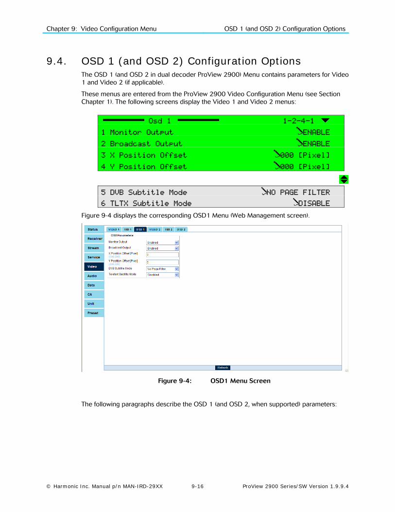
Chapter 9: Video Configuration Menu OSD 1 (and OSD 2) Configuration Options
© Harmonic Inc. Manual p/n MAN-IRD-29XX 9-16 ProView 2900 Series/SW Version 1.9.9.4
9.4. OSD 1 (and OSD 2) Configuration Options The OSD 1 (and OSD 2 in dual decoder ProView 2900) Menu contains parameters for Video 1 and Video 2 (if applicable).
These menus are entered from the ProView 2900 Video Configuration Menu (see Section Chapter 1). The following screens display the Video 1 and Video 2 menus:
Osd 1 1-2-4-1
1 Monitor Output ENABLE
2 Broadcast Output ENABLE
3 X Position Offset 000 [Pixel]
4 Y Position Offset 000 [Pixel]
5 DVB Subtitle Mode NO PAGE FILTER
6 TLTX Subtitle Mode DISABLE
Figure 9-4 displays the corresponding OSD1 Menu (Web Management screen).
Figure 9-4: OSD1 Menu Screen
The following paragraphs describe the OSD 1 (and OSD 2, when supported) parameters:

Chapter 9: Video Configuration Menu OSD 1 (and OSD 2) Configuration Options
© Harmonic Inc. Manual p/n MAN-IRD-29XX 9-17 ProView 2900 Series/SW Version 1.9.9.4
9.4.1. Monitor Output Selecting Monitor Output displays the following screen:
Monitor Output
1 DISABLE
2 ENABLE
The available options are:
• DISABLE – Disables Monitor Output (ProView 2900 rear panel)
• ENABLE – Enables Monitor Output
9.4.2. Broadcast Output Selecting Broadcast Output displays the following screen:
Broadcast Output
1 DISABLE
2 ENABLE
The available options are:
• DISABLE – Disables Broadcast Output (ProView 2900 rear panel)
• ENABLE – Enables Broadcast Output
9.4.3. X Position Offset Selecting X Position Offset displays the following screen:
X Position Offset
+000 [Pixel]
<-300 - +300>
This function determines the horizontal offset of the OSD signal.
The valid range of values is between (-300) and (+300) pixels
9.4.4. Y Position Offset Selecting Y Position Offset displays the following screen:
Y Position Offset
+000 [Pixel]
<-300 - +300>
This function determines the vertical offset of the OSD signal.
The valid range of values is between (-300) and (+300) pixels.

Chapter 9: Video Configuration Menu OSD 1 (and OSD 2) Configuration Options
© Harmonic Inc. Manual p/n MAN-IRD-29XX 9-18 ProView 2900 Series/SW Version 1.9.9.4
9.4.5. DVB Subtitle Mode Selecting DVB Subtitle Mode displays the following screen:
DVB Subtitle Mode
1 DISABLE
2 NO PAGE FILTER
3 USE PAGE FILTER
The available options are:
• DISABLE – Disables DVB Subtitling.
• NO PAGE FILTER – This is the ProView 2900 default setting.
• USE PAGE FILTER – Use this option when more than one DVB subtitling pages exist in the OSD PID. The Page Filter identifies the page that contains actual subtitling data.
9.4.6. TLTX Subtitle Mode Teletext Subtitling requires the decoder to create relevant language fonts. The ProView 2900 has the following Teletext Subtitling fonts installed (all fonts according to ETS 300 706):
• Croatian • Czech • Danish • Dutch • English • English Old • Estonian • Finnish
• French • German • Hungarian • Italian • Latvian • Lithuanian • Norwegian
• Portuguese • Romanian • Serbian • Slovak • Slovenian • Spanish • Swedish
Selecting TLTX Subtitle Mode displays the following screen:
TLTX Subtitle Mode
1 DISABLE
2 ENABLE
The available options are:
• DISABLE – Disables Teletext Subtitling
• ENABLE – Enables Teletext Subtitling
NOTE
When selecting DVB Subtitle Mode, TLTX Subtitle Mode is automatically disabled, and vice versa, since only one set of subtitling is allowed per program.
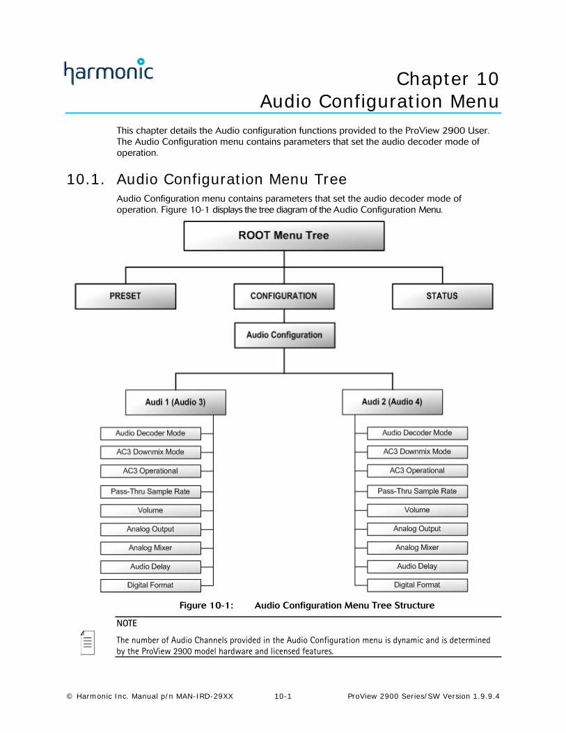
© Harmonic Inc. Manual p/n MAN-IRD-29XX 10-1 ProView 2900 Series/SW Version 1.9.9.4
Chapter 10 Audio Configuration Menu
This chapter details the Audio configuration functions provided to the ProView 2900 User. The Audio Configuration menu contains parameters that set the audio decoder mode of operation.
10.1. Audio Configuration Menu Tree Audio Configuration menu contains parameters that set the audio decoder mode of operation. Figure 10-1 displays the tree diagram of the Audio Configuration Menu.
Figure 10-1: Audio Configuration Menu Tree Structure
NOTE
The number of Audio Channels provided in the Audio Configuration menu is dynamic and is determined by the ProView 2900 model hardware and licensed features.

Chapter 10: Audio Configuration Menu Audio Configuration Menu Tree
© Harmonic Inc. Manual p/n MAN-IRD-29XX 10-2 ProView 2900 Series/SW Version 1.9.9.4
To access the Audio Configuration Menu, in the front panel control interface go to: ConfigurationAudio.
The following screen displays the Audio Configuration Menu:
Audio 1-2-5
1 Audio 1
2 Audio 2
3 Audio 3
4 Audio 4
The available options are: Audio 1 and Audio 2, Audio 3 and Audio 4 (in dual decoder ProView 2900s).
NOTES
Audios 1 through 4 have identical parameters, and are accessible through identical controls. The following is an example of Audio 1 front panel control screen. Audio 2, 3, and 4 control screens are exactly the same (except for the screen header).
Audio1 and Audio2 correspond with Video1 and are always available. Audio3 and Audio4 correspond with Video2 and are available only in dual decoder IRDs.
To access the Audio 1 Menu in the front panel control interface go to ConfigurationAudioAudio1.
The following screen displays the Audio 1 menu:
Audio1(1..2) 1-2-5-1
1 Decoder Mode MUSICAM
2 AC3 Downmix Mode 2/0 L,R STEREO
3 AC3 Operational LINE OUT MODE
4 PassThru Sample Rate 48.0 [KHz]
5 Volume 00.0 [Db]
6 Analog Output UNMUTE (PLAY)
7 Analog Mixer STEREO (L & R)
8 Digital Format Professional
9 Delay 000 [mSec]
10 Test Tone DISABLE

Chapter 10: Audio Configuration Menu Audio Decoder Mode Setup
© Harmonic Inc. Manual p/n MAN-IRD-29XX 10-3 ProView 2900 Series/SW Version 1.9.9.4
Figure 10-2 displays the corresponding Audio1 Menu (Web Management screen).
Figure 10-2: Audio 1 Menu Screen
NOTES
Although AC3 Downmix Mode, AC3 Operational Mode, and PassThru Sample Rate parameters can always be accessed from the Audio (1..4) Parameters window, they are affective only when their corresponding mode is selected in Decoder Mode.
In the Web Management window, AC3 Downmix Mode and AC3 Operational Mode are effective only when Dolby AC3 is selected in Decoder Mode
In the Web Management, window PassThru Sample Rate is effective only when PassThru is selected in Decoder Mode.
Digital Format will be supported by the ProView 2900 Web Control interface in the future SW releases.
The following paragraphs detail the Audio Configuration options.
10.2. Audio Decoder Mode Setup The Audio Decoder mode option allows the user setting the following parameters for an Audio channel:
Decoder Mode
1 MUSICAM
2 DOLBY-AC3
3 AC3 PASSTHRU
4 LINEAR-PCM
5 AUTOMATIC
This menu controls the decoder audio mode; The available options are:
• MUSICAM – Sets the audio decoder mode to MUSICAM

Chapter 10: Audio Configuration Menu Audio AC3 Operational Setup
© Harmonic Inc. Manual p/n MAN-IRD-29XX 10-4 ProView 2900 Series/SW Version 1.9.9.4
• DOLBY-AC3 – Sets the audio decoder mode for the AC-3 downmix
• AC3 PASSTHRU – Sets the audio decoder mode to AC-3 Pass-through
• LINEAR-PCM – Sets the audio decoder mode to Linear PCM and Dolby E Pass-through. Only ProView 2980, ProView 2981, ProView 2991, and ProView 2991 Audio 3 and Audio 4 support this feature
• AUTOMATIC – Automatically detects the audio decoding mode
NOTE
Audio3 and Audio 4 Decoder Mode parameters must be identical .For example: when Audio3 Decoder mode is set to AC3 PASSTHRU, Audio 4 must be set to AC3 PASSTHRU as well.
10.3. AC3 Downmix Mode Setup The AC-3 Downmix mode allows you to set the downmix mode to 2/0.
AC3 Downmix Mode
1 2/0 L,R
2 1/0 C MONO
3 2/0 L,R STEREO
4 3/0 L,C,R
5 2/1 L,R,S
6 3/1 L,C,R,S
7 2/2 L,R,Ls,Rs
8 2/2 L,C,R,Ls,Rs
The available options are: 2/0 L, R, 2/0 C mono, 2/0 L, R stereo, 3/0 L, C, R, 2/1 L, R, S, 3/1 L, C, R, S, 2/2 L, R, Ls, Rs, 2/2 L, C, R, Ls, Rs.
10.4. Audio AC3 Operational Setup The Audio AC3 Operational parameter selects the audio output mode of operation on a specific audio for the Dolby AC-3 processed audio information (for example, Audio 1 output).
AC3 Operational
1 CUSTOM MODE 0
2 CUSTOM MODE 1
3 LINE OUT MODE
4 RF REMOD MODE
The available options are: Custom Mode 0, Custom Mode 1, Line Out Mode, RF Remod Mode. The default for Audio AC-3 Operational output is Line Out mode.
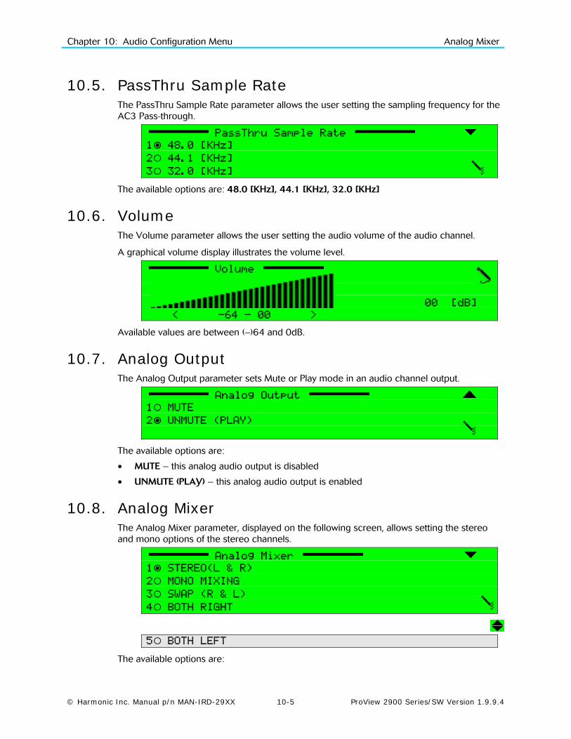
Chapter 10: Audio Configuration Menu Analog Mixer
© Harmonic Inc. Manual p/n MAN-IRD-29XX 10-5 ProView 2900 Series/SW Version 1.9.9.4
10.5. PassThru Sample Rate The PassThru Sample Rate parameter allows the user setting the sampling frequency for the AC3 Pass-through.
PassThru Sample Rate
1 48.0 [KHz]
2 44.1 [KHz]
3 32.0 [KHz]
The available options are: 48.0 [KHz], 44.1 [KHz], 32.0 [KHz]
10.6. Volume The Volume parameter allows the user setting the audio volume of the audio channel.
A graphical volume display illustrates the volume level.
Volume
00 [dB]
< -64 - 00 >
Available values are between (–)64 and 0dB.
10.7. Analog Output The Analog Output parameter sets Mute or Play mode in an audio channel output.
Analog Output
1 MUTE
2 UNMUTE (PLAY)
The available options are:
• MUTE – this analog audio output is disabled
• UNMUTE (PLAY) – this analog audio output is enabled
10.8. Analog Mixer The Analog Mixer parameter, displayed on the following screen, allows setting the stereo and mono options of the stereo channels.
Analog Mixer
1 STEREO(L & R)
2 MONO MIXING
3 SWAP (R & L)
4 BOTH RIGHT
5 BOTH LEFT
The available options are:

Chapter 10: Audio Configuration Menu Test Tone
© Harmonic Inc. Manual p/n MAN-IRD-29XX 10-6 ProView 2900 Series/SW Version 1.9.9.4
• STEREO (L & R) – Standard stereo output on the respective left and right connectors
• MONO MIXING – Mixes left and right stereo channel signals for mono output on both left and right connectors
• SWAP (R & L) – Swaps channels:
• Left channel on right connectors
• Right channel on left connectors
• BOTH RIGHT – Outputs right channels on both left and right connectors
• BOTH LEFT – Outputs left channels on both left and right connectors
10.9. Digital Format The Digital Format parameter sets the digital audio channel output mode.
Digital Format
1 CONSUMER
2 PROFESSIONAL
The available options are:
• CONSUMER – Selects AES/EBU, SPDIF Consumer Mode. – This mode passes the audio mode bits as is.
• PROFESSIONAL – Selects AES/EBU Professional Mode. This mode set the audio mode to stereo regardless of actual audio.
10.10. Audio Delay The Audio Delay parameter sets the delay time for the received audio:
The following figure illustrates the Audio Delay setup screen.
DELAY
000 [mSec]
<-128 - +128>
Available delay time ranges from -128 to +128 mSec.
10.11. Test Tone The ProView 2900 can create a 1 kHz audio test signal, and output it through any of its audio outputs for testing that audio output performance. The operator must select the audio output to be tested and enable the creation of the test tone for that output.
Test Tone
1 DISABLE
2 1000 Hz
The available options are:
Chapter 10: Audio Configuration Menu Test Tone
© Harmonic Inc. Manual p/n MAN-IRD-29XX 10-7 ProView 2900 Series/SW Version 1.9.9.4
DISABLE – disables the test tone
1000 Hz – creates a 1 kHz audio signal and outputs it through this Audio output
NOTES
It is required to stop all ProView 2900 decoding before performing the Audio Output testing.
Only Audio Outputs 1, 3, and 4 can currently be tested using the ProView 2900 internal 1 kHz test tone.
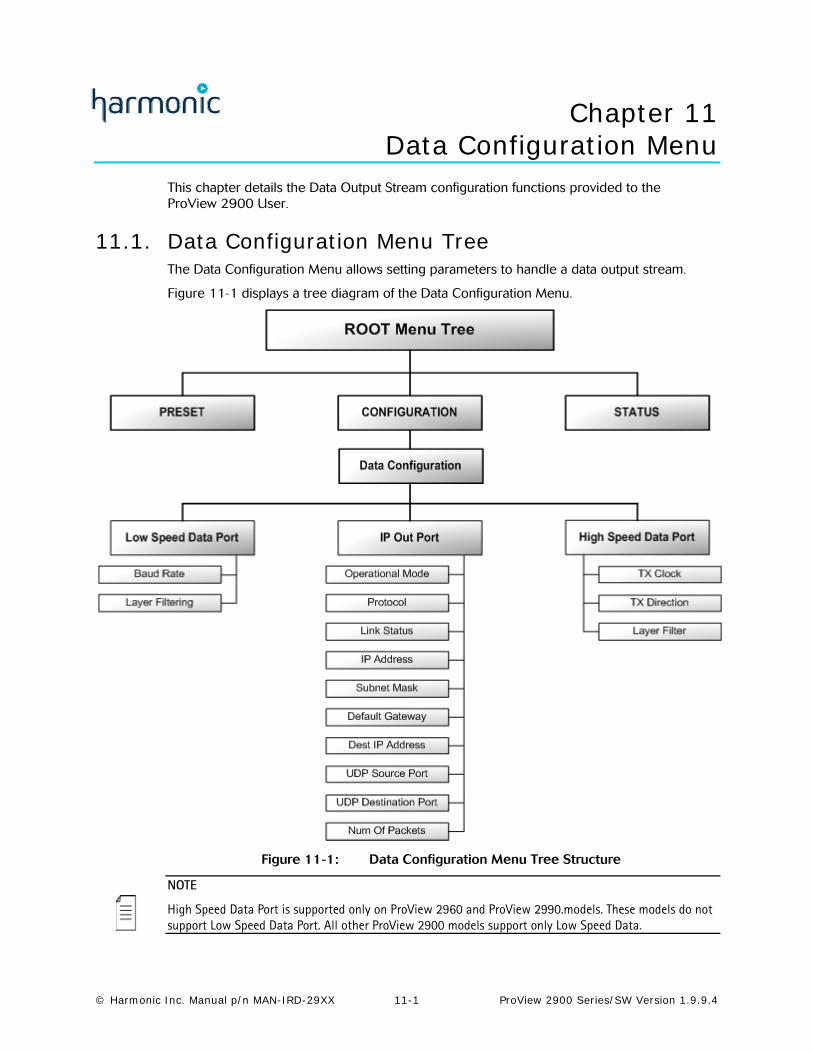
© Harmonic Inc. Manual p/n MAN-IRD-29XX 11-1 ProView 2900 Series/SW Version 1.9.9.4
Chapter 11 Data Configuration Menu
This chapter details the Data Output Stream configuration functions provided to the ProView 2900 User.
11.1. Data Configuration Menu Tree The Data Configuration Menu allows setting parameters to handle a data output stream.
Figure 11-1 displays a tree diagram of the Data Configuration Menu.
Figure 11-1: Data Configuration Menu Tree Structure
NOTE
High Speed Data Port is supported only on ProView 2960 and ProView 2990.models. These models do not support Low Speed Data Port. All other ProView 2900 models support only Low Speed Data.
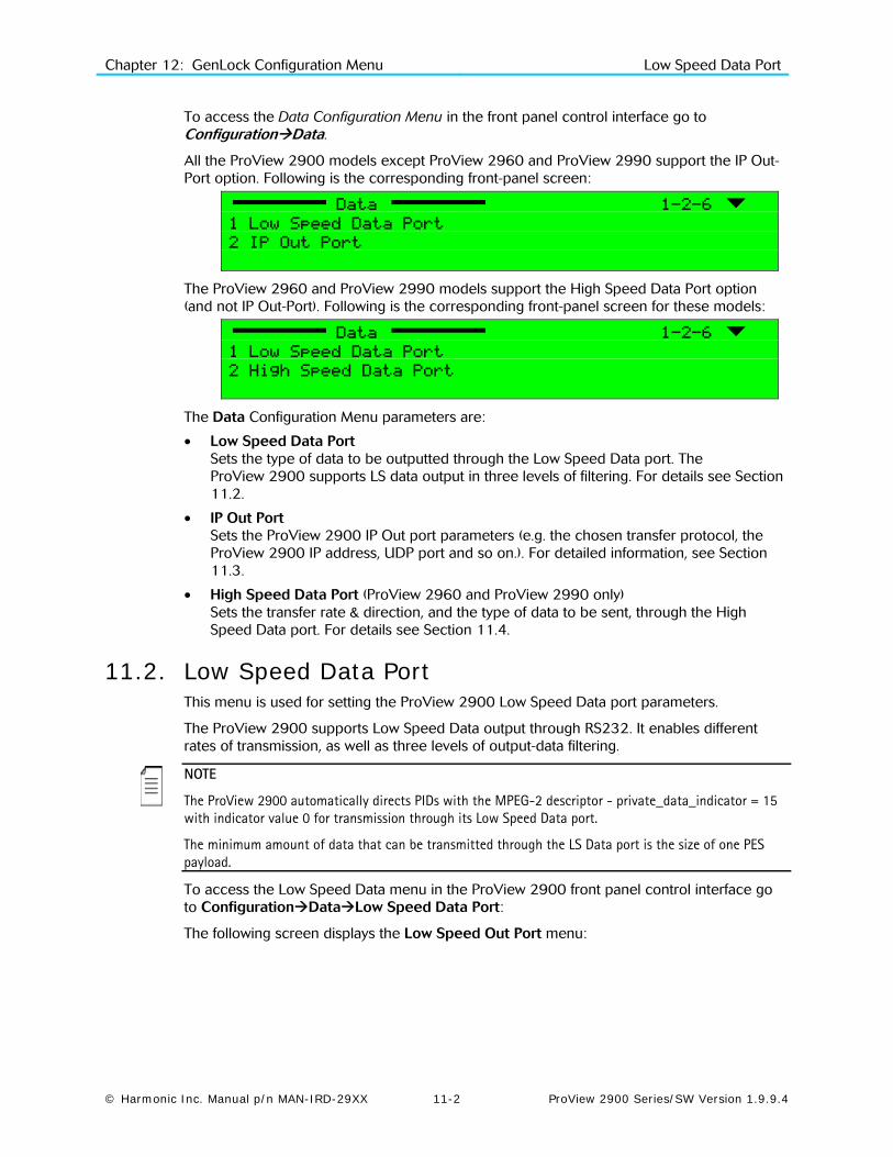
Chapter 12: GenLock Configuration Menu Low Speed Data Port
© Harmonic Inc. Manual p/n MAN-IRD-29XX 11-2 ProView 2900 Series/SW Version 1.9.9.4
To access the Data Configuration Menu in the front panel control interface go to ConfigurationData.
All the ProView 2900 models except ProView 2960 and ProView 2990 support the IP Out-Port option. Following is the corresponding front-panel screen:
Data 1-2-6
1 Low Speed Data Port
2 IP Out Port
The ProView 2960 and ProView 2990 models support the High Speed Data Port option (and not IP Out-Port). Following is the corresponding front-panel screen for these models:
Data 1-2-6
1 Low Speed Data Port
2 High Speed Data Port
The Data Configuration Menu parameters are:
• Low Speed Data Port Sets the type of data to be outputted through the Low Speed Data port. The ProView 2900 supports LS data output in three levels of filtering. For details see Section 11.2.
• IP Out Port Sets the ProView 2900 IP Out port parameters (e.g. the chosen transfer protocol, the ProView 2900 IP address, UDP port and so on.). For detailed information, see Section 11.3.
• High Speed Data Port (ProView 2960 and ProView 2990 only) Sets the transfer rate & direction, and the type of data to be sent, through the High Speed Data port. For details see Section 11.4.
11.2. Low Speed Data Port This menu is used for setting the ProView 2900 Low Speed Data port parameters.
The ProView 2900 supports Low Speed Data output through RS232. It enables different rates of transmission, as well as three levels of output-data filtering.
NOTE
The ProView 2900 automatically directs PIDs with the MPEG-2 descriptor - private_data_indicator = 15 with indicator value 0 for transmission through its Low Speed Data port.
The minimum amount of data that can be transmitted through the LS Data port is the size of one PES payload.
To access the Low Speed Data menu in the ProView 2900 front panel control interface go to ConfigurationDataLow Speed Data Port:
The following screen displays the Low Speed Out Port menu:

Chapter 12: GenLock Configuration Menu Low Speed Data Port
© Harmonic Inc. Manual p/n MAN-IRD-29XX 11-3 ProView 2900 Series/SW Version 1.9.9.4
Low Speed Data Port 1-2-6-1
1 Baud Rate 115200 [Baud]
2 Layer Filtering P.E.S Payload
To access the Low Speed Data menu in the ProView 2900 web management window go to DataLow Speed Data Port: Figure 10-2 displays the corresponding LS Data Port menu (Web Management screen).
Figure 11-2: Low Speed Data Configuration Menu
The Low Speed Date Port Configuration Menu provides access to the following parameters:
• Baud Rate, enables selecting the LS data transmission rate.
• Layer Filtering, enables selecting the LS data filtering, determining the type of data to be transmitted through the LS Data port.
11.2.1. Baud Rate This parameter enables electing between eight possible LS data transmission rates. Following is the corresponding front panel screen:
Baud Rate
1 1200 [Baud]
2 2400 [Baud]
3 4800 [Baud]
4 9600 [Baud]
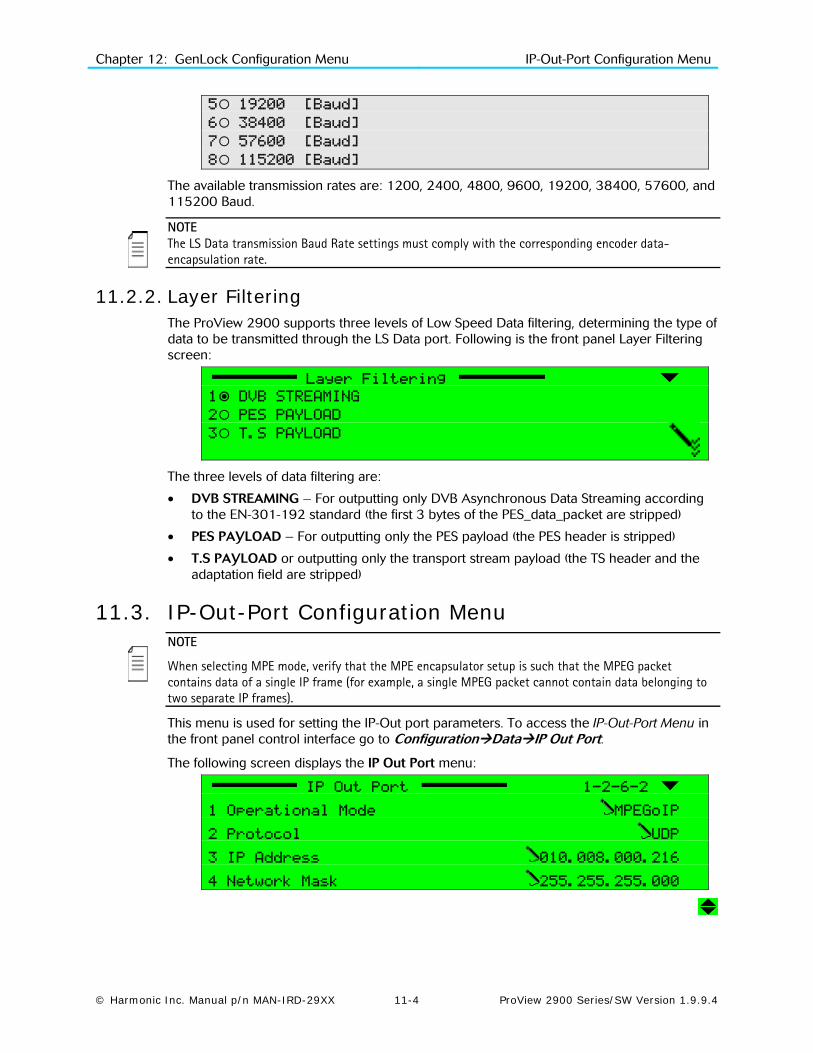
Chapter 12: GenLock Configuration Menu IP-Out-Port Configuration Menu
© Harmonic Inc. Manual p/n MAN-IRD-29XX 11-4 ProView 2900 Series/SW Version 1.9.9.4
5 19200 [Baud]
6 38400 [Baud]
7 57600 [Baud]
8 115200 [Baud]
The available transmission rates are: 1200, 2400, 4800, 9600, 19200, 38400, 57600, and 115200 Baud.
NOTE The LS Data transmission Baud Rate settings must comply with the corresponding encoder data-encapsulation rate.
11.2.2. Layer Filtering The ProView 2900 supports three levels of Low Speed Data filtering, determining the type of data to be transmitted through the LS Data port. Following is the front panel Layer Filtering screen:
Layer Filtering
1 DVB STREAMING
2 PES PAYLOAD
3 T.S PAYLOAD
The three levels of data filtering are:
• DVB STREAMING – For outputting only DVB Asynchronous Data Streaming according to the EN-301-192 standard (the first 3 bytes of the PES_data_packet are stripped)
• PES PAYLOAD – For outputting only the PES payload (the PES header is stripped)
• T.S PAYLOAD or outputting only the transport stream payload (the TS header and the adaptation field are stripped)
11.3. IP-Out-Port Configuration Menu NOTE
When selecting MPE mode, verify that the MPE encapsulator setup is such that the MPEG packet contains data of a single IP frame (for example, a single MPEG packet cannot contain data belonging to two separate IP frames).
This menu is used for setting the IP-Out port parameters. To access the IP-Out-Port Menu in the front panel control interface go to ConfigurationDataIP Out Port.
The following screen displays the IP Out Port menu:
IP Out Port 1-2-6-2
1 Operational Mode MPEGoIP
2 Protocol UDP
3 IP Address 010.008.000.216
4 Network Mask 255.255.255.000
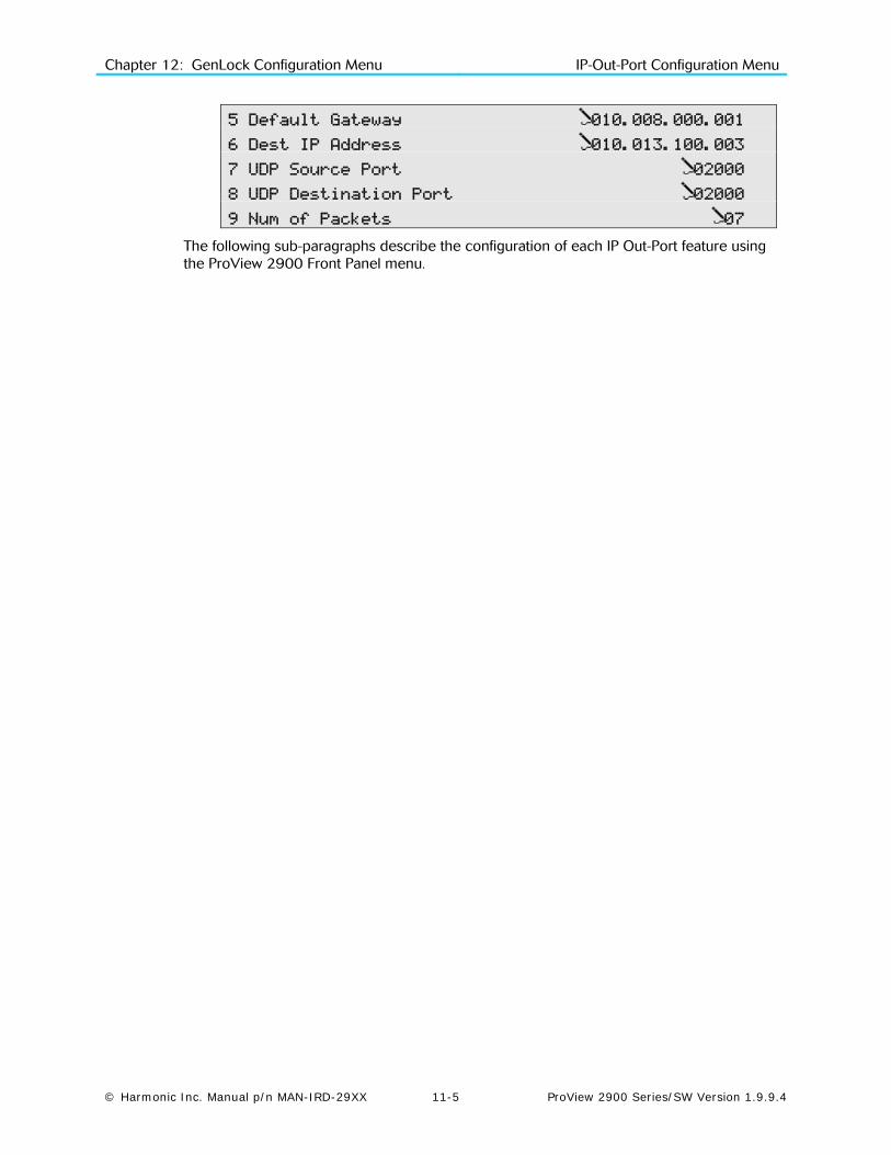
Chapter 12: GenLock Configuration Menu IP-Out-Port Configuration Menu
© Harmonic Inc. Manual p/n MAN-IRD-29XX 11-5 ProView 2900 Series/SW Version 1.9.9.4
5 Default Gateway 010.008.000.001
6 Dest IP Address 010.013.100.003
7 UDP Source Port 02000
8 UDP Destination Port 02000
9 Num of Packets 07
The following sub-paragraphs describe the configuration of each IP Out-Port feature using the ProView 2900 Front Panel menu.

Chapter 12: GenLock Configuration Menu IP-Out-Port Configuration Menu
© Harmonic Inc. Manual p/n MAN-IRD-29XX 11-6 ProView 2900 Series/SW Version 1.9.9.4
To access the IP Out Port menu in the ProView 2900 web management window go to DataIP Data Port: Figure 11-3 displays the corresponding IP Data Port menu.
Figure 11-3: IP Data Port Menu Screen
The IP Data Port Window in the Web Manager provide access to set-up all IP Out-Port parameters, grouped differently than the Front Panel menu:
• Port Parameters, including the IP Address (see paragraph 11.3.3), the Subnet Mask address (see paragraph 11.3.4), the Default Gateway address (see paragraph 11.3.5), and the Link Enable control (ON/OFF switch).
• Stream Parameters, including the Operational Mode (see paragraph 11.3.1), the Protocol format (see paragraph 11.3.3), the Destination IP Address (see paragraph 11.3.6), the UDP Source Port (see paragraph 11.3.3), the UDP Destination Port (see paragraph 11.3.8), and the Number of Packets thransmited (see paragraph 11.3.3).
11.3.1. Operational Mode The Operational Mode screen displays the currently active mode of operation and allows setting the mode using the following Select Value screen:
Operational Mode
1 MPEGoIp
2 MPE
The available options are:
• MPEGoIp – MPEG-over-IP mode
• MPE – IP data (MPE de-capsulation)
NOTE
When Operational mode is set to MPEG-over-IP, all other items in the IP-Out-Port menu must be configured. When Operational mode is set to MPE, then the IP address, Subnet Mask, and Default Gateway items must be configured.

Chapter 12: GenLock Configuration Menu IP-Out-Port Configuration Menu
© Harmonic Inc. Manual p/n MAN-IRD-29XX 11-7 ProView 2900 Series/SW Version 1.9.9.4
11.3.2. Protocol The Protocol screen displays the currently active L3 protocol and allows setting the protocol using the following Select Value screen.
Protocol
1 UDP
2 RTP
The available options are:
• UDP – User Datagram Protocol
• RTP – Real Time Protocol (this feature will be supported in future software releases)
11.3.3. IP Address The IP Address parameter allows setting the IP Address of the output port.
IP Address
010.008.000.216
The value in each field must be a whole number between 0 and 255.
11.3.4. Subnet Mask The Subnet Mask parameter defines the network sub-mask.
Subnet Mask
255.255.255.000
The value in each field must be a whole number between 0 and 255.
11.3.5. Default Gateway The Default Gateway parameter allows setting the network default gateway address. This is the address of a local IP router on the same network as the ProView 2900 that is used to forward traffic beyond the local network.
Default Gateway
010.008.000.001
The value in each field must be a whole number between 0 and 255.
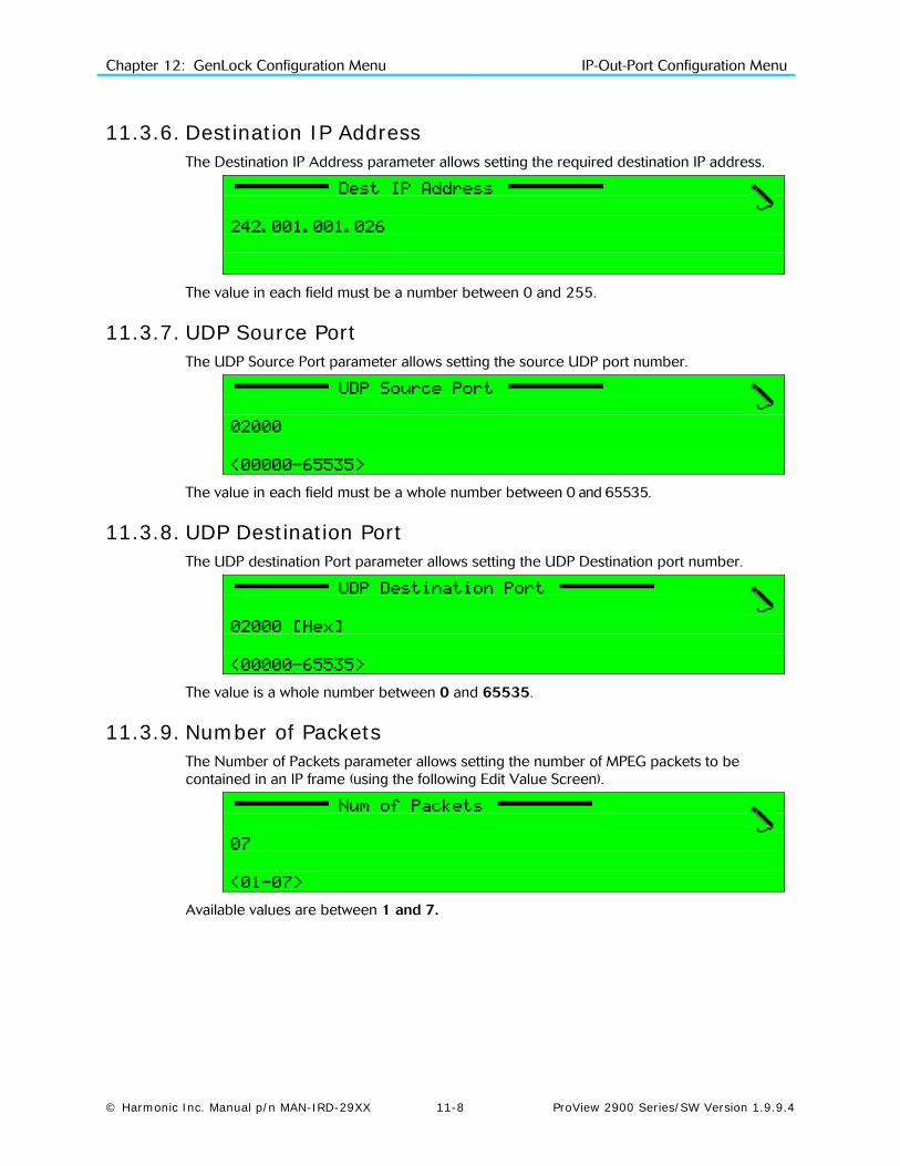
Chapter 12: GenLock Configuration Menu IP-Out-Port Configuration Menu
© Harmonic Inc. Manual p/n MAN-IRD-29XX 11-8 ProView 2900 Series/SW Version 1.9.9.4
11.3.6. Destination IP Address The Destination IP Address parameter allows setting the required destination IP address.
Dest IP Address
242.001.001.026
The value in each field must be a number between 0 and 255.
11.3.7. UDP Source Port The UDP Source Port parameter allows setting the source UDP port number.
UDP Source Port
02000
<00000-65535>
The value in each field must be a whole number between 0 and 65535.
11.3.8. UDP Destination Port The UDP destination Port parameter allows setting the UDP Destination port number.
UDP Destination Port
02000 [Hex]
<00000-65535>
The value is a whole number between 0 and 65535.
11.3.9. Number of Packets The Number of Packets parameter allows setting the number of MPEG packets to be contained in an IP frame (using the following Edit Value Screen).
Num of Packets
07
<01-07>
Available values are between 1 and 7.
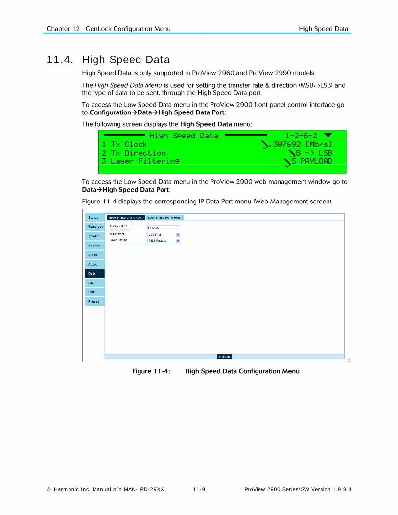
Chapter 12: GenLock Configuration Menu High Speed Data
© Harmonic Inc. Manual p/n MAN-IRD-29XX 11-9 ProView 2900 Series/SW Version 1.9.9.4
11.4. High Speed Data High Speed Data is only supported in ProView 2960 and ProView 2990 models.
The High Speed Data Menu is used for setting the transfer rate & direction (MSB↔LSB) and the type of data to be sent, through the High Speed Data port.
To access the Low Speed Data menu in the ProView 2900 front panel control interface go to ConfigurationDataHigh Speed Data Port:
The following screen displays the High Speed Data menu:
High Speed Data 1-2-6-2
1 Tx Clock 08.307692 [Mb/s]
2 Tx Direction MSB -> LSB
3 Layer Filtering T.S PAYLOAD
To access the Low Speed Data menu in the ProView 2900 web management window go to DataHigh Speed Data Port:
Figure 11-4 displays the corresponding IP Data Port menu (Web Management screen).
Figure 11-4: High Speed Data Configuration Menu
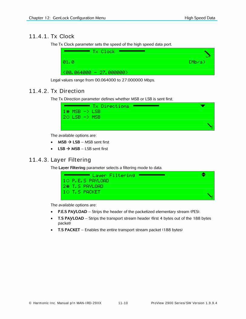
Chapter 12: GenLock Configuration Menu High Speed Data
© Harmonic Inc. Manual p/n MAN-IRD-29XX 11-10 ProView 2900 Series/SW Version 1.9.9.4
11.4.1. Tx Clock The Tx Clock parameter sets the speed of the high speed data port.
Tx Clock
01.0 [Mb/s)
<00.064000 - 27.000000>
Legal values range from 00.064000 to 27.000000 Mbps.
11.4.2. Tx Direction The Tx Direction parameter defines whether MSB or LSB is sent first.
Tx Directions
1 MSB -> LSB
2 LSB -> MSB
The available options are:
• MSB LSB – MSB sent first
• LSB MSB – LSB sent first
11.4.3. Layer Filtering The Layer Filtering parameter selects a filtering mode to data.
Layer Filtering
1 P.E.S PAYLOAD
2 T.S PAYLOAD
1 T.S PACKET
The available options are:
• P.E.S PAYLOAD – Strips the header of the packetized elementary stream (PES).
• T.S PAYLOAD – Strips the transport stream header (first 4 bytes out of the 188 bytes packet)
• T.S PACKET – Enables the entire transport stream packet (188 bytes)
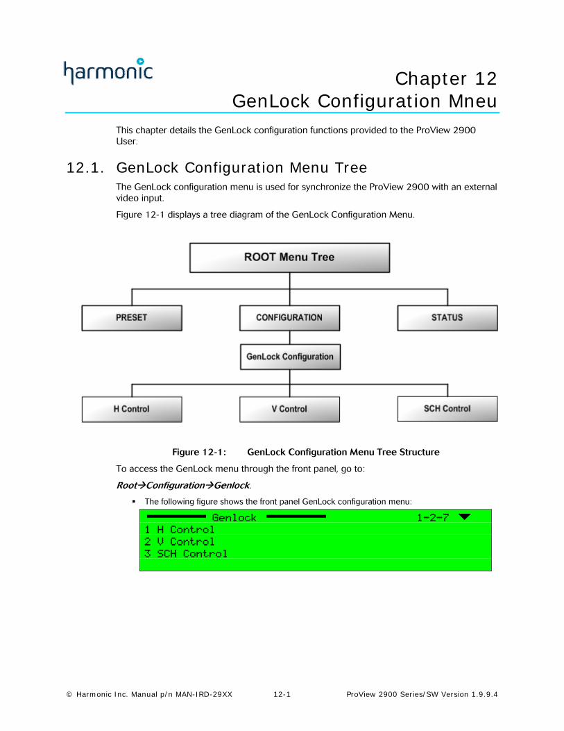
© Harmonic Inc. Manual p/n MAN-IRD-29XX 12-1 ProView 2900 Series/SW Version 1.9.9.4
Chapter 12 GenLock Configuration Mneu
This chapter details the GenLock configuration functions provided to the ProView 2900 User.
12.1. GenLock Configuration Menu Tree The GenLock configuration menu is used for synchronize the ProView 2900 with an external video input.
Figure 12-1 displays a tree diagram of the GenLock Configuration Menu.
Figure 12-1: GenLock Configuration Menu Tree Structure
To access the GenLock menu through the front panel, go to:
RootConfigurationGenlock.
The following figure shows the front panel GenLock configuration menu:
Genlock 1-2-7
1 H Control
2 V Control
3 SCH Control
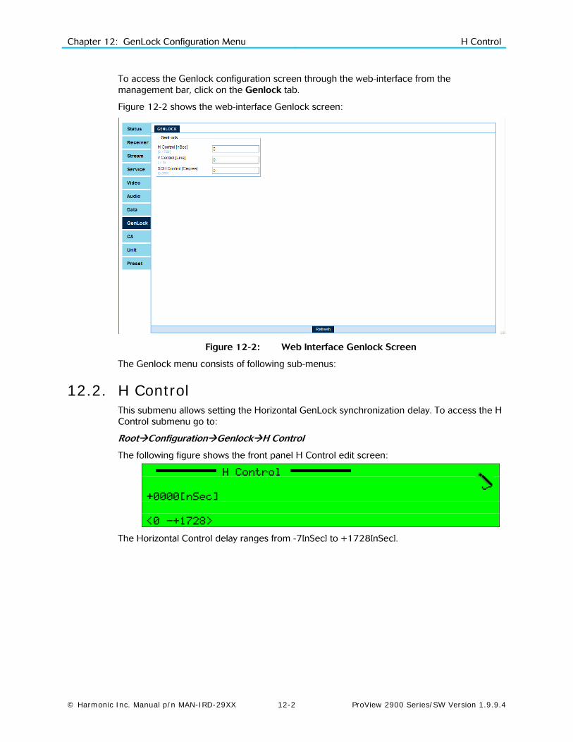
Chapter 12: GenLock Configuration Menu H Control
© Harmonic Inc. Manual p/n MAN-IRD-29XX 12-2 ProView 2900 Series/SW Version 1.9.9.4
To access the Genlock configuration screen through the web-interface from the management bar, click on the Genlock tab.
Figure 12-2 shows the web-interface Genlock screen:
Figure 12-2: Web Interface Genlock Screen
The Genlock menu consists of following sub-menus:
12.2. H Control This submenu allows setting the Horizontal GenLock synchronization delay. To access the H Control submenu go to:
RootConfigurationGenlockH Control
The following figure shows the front panel H Control edit screen:
H Control
+0000[nSec]
<0 -+1728>
The Horizontal Control delay ranges from -7[nSec] to +1728[nSec].

Chapter 12: GenLock Configuration Menu SCH Control
© Harmonic Inc. Manual p/n MAN-IRD-29XX 12-3 ProView 2900 Series/SW Version 1.9.9.4
12.3. V Control This submenu allows setting the Vertical GenLock Line. To access the V Control submenu go to: RootConfigurationGenlockV Control
The following figure shows the front panel V Control edit screen:
V Control
+00 [Line]
<-7 -+06>
The Vertical Control delay ranges from -7[Line] to +6[Line].
12.4. SCH Control This submenu allows setting the GenLock phase. To access the SCH Control submenu go to: RootConfigurationGenlockSCH Control
The following figure shows the front panel SCH Control edit screen:
SCH Control
+000[Degree]
<0 -+360>
The Vertical Control delay ranges from 0 to 360 degrees.

© Harmonic Inc. Manual p/n MAN-IRD-29XX 13-1 ProView 2900 Series/SW Version 1.9.9.4
Chapter 13 Conditional Access Configuration Menu
This chapter details the Conditional Access configuration functions provided to the ProView 2900 User.
13.1. CA Configuration Menu Tree This menu allows access to all ProView 2900 CA (Conditional Access) parameters.
Figure 13-1 displays a tree diagram of the Conditional Access Configuration Menu.
Figure 13-1: Conditional Access Configuration Menu Tree Structure

Chapter 13: CA Configuration Menu CA Configuration Menu Tree
© Harmonic Inc. Manual p/n MAN-IRD-29XX 13-2 ProView 2900 Series/SW Version 1.9.9.4
To access the Conditional Access Configuration menu in the front panel control interface go to Configuration Conditional Access.
The following screen displays the Conditional Access menu:
Conditional Access 1-2-7
1 Common Interface
2 BISS
3 Embedded
To access the Conditional Access configuration screen through the web-interface from the management bar, click on the CA tab.
Figure 13-2 shows the web-interface CA screen:
Figure 13-2: Web Interface Conditional Access Screen
The Conditional Access Menu parameters are as follows:
• Common Interface (CI) Enable setting up the configuration of the CAMS in the ProView 2900 using the DVB-CI standard. For details, see Section 13.2.
• BISS Mode Enable setting up the BISS encryption mode. For details, see Section 0.
• Embedded Mode Enable setting up the embedded encryption mode. For details, see Section 13.3.2.

Chapter 13: CA Configuration Menu Common Interface Configuration Menu
© Harmonic Inc. Manual p/n MAN-IRD-29XX 13-3 ProView 2900 Series/SW Version 1.9.9.4
13.2. Common Interface Configuration Menu The Common Interface (CI) menu displays the current status of the ProView 2900 CI slots. To access the Common Interface menu in the front panel control interface go to ConfigurationConditional AccessCommon Interface.
The following screen displays the Common Interface menu:
Common Interface 1-2-7-1
1 Slot 1
2 Slot 2
To access the Common Interface configuration screen through the web-interface go to CACommon Interface tab.
Figure 13-3 shows the web-interface Common Interface screen:
Figure 13-3: Web Interface Common Interface Screen
Once a CI Slot is selected from the front panel, an Edit Menu screen is displayed. The Slot 1 and Slot 2 Configuration edit menu provides access to the CI parameters for the respective ProView 2900 CI Slot:
Slot (1..2) 1-2-7-1-1
1 Operation ENABLE
2 Send MMI Command MENU-menu
3 Send PIN Code 1111
The following paragraphs detail the Slot Configuration options.
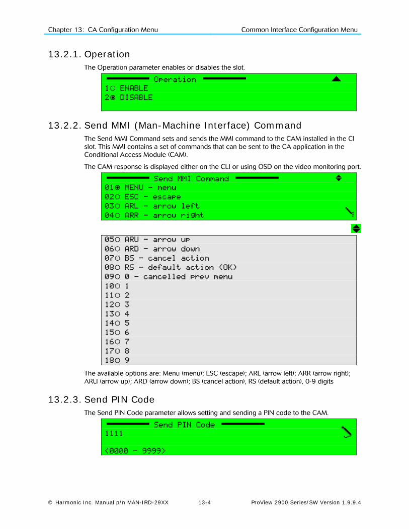
Chapter 13: CA Configuration Menu Common Interface Configuration Menu
© Harmonic Inc. Manual p/n MAN-IRD-29XX 13-4 ProView 2900 Series/SW Version 1.9.9.4
13.2.1. Operation The Operation parameter enables or disables the slot.
Operation
1 ENABLE
2 DISABLE
13.2.2. Send MMI (Man-Machine Interface) Command The Send MMI Command sets and sends the MMI command to the CAM installed in the CI slot. This MMI contains a set of commands that can be sent to the CA application in the Conditional Access Module (CAM).
The CAM response is displayed either on the CLI or using OSD on the video monitoring port.
Send MMI Command
01 MENU - menu
02 ESC - escape
03 ARL -–arrow left
04 ARR - arrow right
05 ARU–- arrow up
06 ARD - arrow down
07 BS - cancel action
08 RS - default action (OK)
09 0 - cancelled prev menu
10 1
11 2
12 3
13 4
14 5
15 6
16 7
17 8
18 9
The available options are: Menu (menu); ESC (escape); ARL (arrow left); ARR (arrow right); ARU (arrow up); ARD (arrow down); BS (cancel action), RS (default action), 0-9 digits
13.2.3. Send PIN Code The Send PIN Code parameter allows setting and sending a PIN code to the CAM.
Send PIN Code
1111
<0000 - 9999>

Chapter 13: CA Configuration Menu BISS Mode
© Harmonic Inc. Manual p/n MAN-IRD-29XX 13-5 ProView 2900 Series/SW Version 1.9.9.4
13.3. BISS Mode The ProView 2900 supports the following encryption modes:
• Even-Odd Encryption (‘Harmonic private’ mode)
• BISS Mode 1
• BISS-E Clear Session Word
• BISS-E with Injected ID
• BISS-E with Buried ID
These BISS options operate according to the EBU-UER Tech 3292 manual.
Even-Odd Encryption is a Harmonic-developed encryption option that uses both an even and an odd key. This is another encryption option that is available for the operator.
The following screen displays the BISS menu navigation screen:
BISS 1-2-7-2
1 TV1
2 TV2
3 General
To access the BISS configuration screen through the web-interface go to CABISS tab.
Figure 13-4 shows the web-interface BISS screen:
Figure 13-4: Web Interface BISS Screen
The BISS Menu parameters are:
• TV(1..2) - Enables the operator to set Encryption Keys values of the selected CA mode
• General – Allows the operator to select between the different encryption modes

Chapter 13: CA Configuration Menu BISS Mode
© Harmonic Inc. Manual p/n MAN-IRD-29XX 13-6 ProView 2900 Series/SW Version 1.9.9.4
13.3.1. General The General menu in the Encryption branch displays the current encryption mode and enables the operator to change the mode.
General 1-2-7-2-2
Encryption Mode EVEN-ODD
Selecting the Encryption Mode option in the General menu allows the operator to select between the decoder's different encryption modes.
Encryption Mode
1 EVEN-ODD
2 BISS-MODE 1
3 BISS-E-CLEAR SW
4 BISS-E-INJECTED ID
05 BISS-E-BURIED ID
13.3.2. TV1 The following screen displays the TV1 Edit Menu Screen, when the encryption mode is set to EVEN-ODD mode.
TV1 1-2-7-2
1 Even Key 000000-000000
2 Odd Key 000000-000000
The TV1 menu available parameters are:
• Even Key: Allows operator to set the Even Key encryption value
• Odd Key: Allows operator to set the Odd Key encryption value
The following screen displays the TV1 Edit Menu Screen, when the encryption mode is set to one of the BISS modes (BISS-MODE 1,BISS-E-CLEAR SW, BISS-E-INJECTED ID, BISS-E-BURIED ID).
TV1 1-2-7-2
1 Encription Key0 000000-000000

Chapter 13: CA Configuration Menu Automatic CAM Reset
© Harmonic Inc. Manual p/n MAN-IRD-29XX 13-7 ProView 2900 Series/SW Version 1.9.9.4
13.4. Embedded Mode This feature will be supported in the future software releases.
13.5. Automatic CAM Reset Automatic CAM Reset mechanism handles scenarios where the CAM ceases to function correctly, resulting in no decryption of services and therefore video stop or freezing. Although frozen, the video output remains a valid signal.
The ProView 2900 detects CAM errors by performing a video lock test that recognizes faulty video output signals which last longer then the configurable threshold time.
When an error is detected, the ProView 2900 automatically resets the CAM. Reset time may take 10 to 20 seconds.
The CAM Timeout can be configured through CLI. To configure the CAM Timeout through the CLI:
1. Go to config/video/general/
2. Set decoding timeout by using the following command:
<port(1/2)> < timeout (seconds), or 0 = disable>
The default CAM Timeout is 10 seconds.
To disable the Automatic CAM reset mechanism set the timeout value to 0.
NOTE
Harmonic recommends setting the CAM Timeout value to five seconds or higher.

© Harmonic Inc. Manual p/n MAN-IRD-29XX 14-1 ProView 2900 Series/SW Version 1.9.9.4
Chapter 14 Unit Configuration Menu
This chapter details the ProView 2900 Unit configuration functions provided to the ProView 2900 User.
14.1. Unit Configuration Menu Tree The Unit Configuration menu allows setting general ProView 2900 parameters.
Figure 14-1 displays a tree diagram of the Unit configuration menu.
Figure 14-1: Unit Configuration Menu

Chapter 14: Unit Configuration Menu Unit Configuration Menu Tree
© Harmonic Inc. Manual p/n MAN-IRD-29XX 14-2 ProView 2900 Series/SW Version 1.9.9.4
To access the Unit configuration menu from the front panel, go to ConfigurationUnit.
The following screen illustrates the Unit menu:
Unit 1-2-8
1 General
2 Serial Control Port
3 Ethernet Management Port
4 Licensing
5 Dry Contact
To access the Unit configuration screen from the Web interface, click the Unit Tab. Figure 14-2 displays the Web interface Unit screen.
Figure 14-2: Web Interface - Unit Screen
The Unit configuration includes the following sub-menus:
General – For details see Section 14.2.
Change Password – For details see Section 14.3.
Control Passwords - For details see Section 14.4.
Serial Control Port – For details see Section 14.5.
Ethernet Management Port - For details see Section 14.6.
Licensing - For details see Section 14.7.
Dry Contact (Alarms and GPI) – For details see Section 14.8.
Trap Menu - For details see Section 14.9.
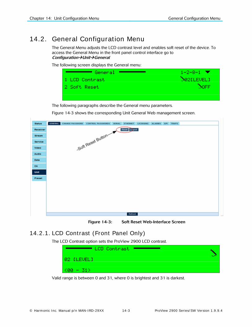
Chapter 14: Unit Configuration Menu General Configuration Menu
© Harmonic Inc. Manual p/n MAN-IRD-29XX 14-3 ProView 2900 Series/SW Version 1.9.9.4
14.2. General Configuration Menu The General Menu adjusts the LCD contrast level and enables soft reset of the device. To access the General Menu in the front panel control interface go to ConfigurationUnitGeneral.
The following screen displays the General menu:
General 1-2-8-1
1 LCD Contrast 02[LEVEL]
2 Soft Reset OFF
The following paragraphs describe the General menu parameters.
Figure 14-3 shows the corresponding Unit General Web management screen.
Figure 14-3: Soft Reset Web-Interface Screen
14.2.1. LCD Contrast (Front Panel Only) The LCD Contrast option sets the ProView 2900 LCD contrast.
LCD Contrast
02 [LEVEL]
<00 - 31>
Valid range is between 0 and 31, where 0 is brightest and 31 is darkest.
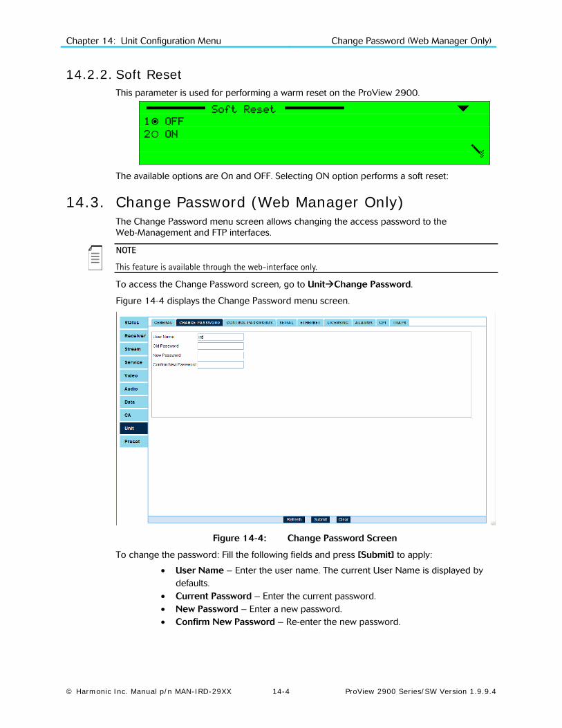
Chapter 14: Unit Configuration Menu Change Password (Web Manager Only)
© Harmonic Inc. Manual p/n MAN-IRD-29XX 14-4 ProView 2900 Series/SW Version 1.9.9.4
14.2.2. Soft Reset This parameter is used for performing a warm reset on the ProView 2900.
Soft Reset
1 OFF
2 ON
The available options are On and OFF. Selecting ON option performs a soft reset:
14.3. Change Password (Web Manager Only) The Change Password menu screen allows changing the access password to the Web-Management and FTP interfaces.
NOTE
This feature is available through the web-interface only.
To access the Change Password screen, go to UnitChange Password.
Figure 14-4 displays the Change Password menu screen.
Figure 14-4: Change Password Screen
To change the password: Fill the following fields and press [Submit] to apply:
• User Name – Enter the user name. The current User Name is displayed by defaults.
• Current Password – Enter the current password. • New Password – Enter a new password. • Confirm New Password – Re-enter the new password.

Chapter 14: Unit Configuration Menu Control Passwords (Web Manager Only)
© Harmonic Inc. Manual p/n MAN-IRD-29XX 14-5 ProView 2900 Series/SW Version 1.9.9.4
14.4. Control Passwords (Web Manager Only) The Control Passwords screen allows enabling and disabling the WEB and FTP passwords.
NOTE
This feature is available through the web-interface only.
To access the Control Password screen, go to: UnitControl Passwords
Figure 14-5 displays the Control Passwords menu screen.
Figure 14-5: Control Password Screen
The Control Passwords screen includes two fields:
FTP Password – Allows enabling or disabling the FTP password.
WEB Password – Allows enabling or disabling the WEB password.

Chapter 14: Unit Configuration Menu Serial Control Port Configuration
© Harmonic Inc. Manual p/n MAN-IRD-29XX 14-6 ProView 2900 Series/SW Version 1.9.9.4
14.5. Serial Control Port Configuration The Serial Control Port menu allows the user setting the serial control port parameters.
To access the Serial Control Port Menu in the front panel control interface go to ConfigurationUnit Serial Control Port.
The following screen displays the Serial Control Port menu:
Serial Control Port 1-2-8-2
1 HW Interface RS232
2 SW Protocol TERMINAL ECHO
3 Baud Rate 115200 [Baud]
4 Address FFFF
Figure 14-6 shows the corresponding Unit Serial Web management screen.
Figure 14-6: Unit Serial Screen
The following paragraphs detail the Unit Serial Control Port configuration options.
14.5.1. HW Interface HW Interface
1 RS232
2 RS485
The available options are: RS-232 and RS-485

Chapter 14: Unit Configuration Menu Serial Control Port Configuration
© Harmonic Inc. Manual p/n MAN-IRD-29XX 14-7 ProView 2900 Series/SW Version 1.9.9.4
14.5.2. SW Protocol SW Protocol
1 TERMINAL ECHO
2 TERMINAL NO-ECHO
3 MASTER-SLAVE
The available options are:
• Terminal Echo
• Terminal No-Echo
• Master-Slave
14.5.3. Baud Rate Baud Rate
1 4800 [Baud]
2 9600 [Baud]
3 19200 [Baud]
4 38400 [Baud]
5 57600 [Baud]
6 115200 [Baud]
The available options are: 4800, 9600, 19200, 38400, 57600, 115200 Baud
14.5.4. Address Address
FFFF [HEX]
<0000-FFFF>
Valid range is between 0 and FFFF (Hexadecimal).

Chapter 14: Unit Configuration Menu Ethernet Management Port
© Harmonic Inc. Manual p/n MAN-IRD-29XX 14-8 ProView 2900 Series/SW Version 1.9.9.4
14.6. Ethernet Management Port The Ethernet menu allows setting the Ethernet management port parameters.
To access the Ethernet Management Port menu in the front panel control interface go to ConfigurationUnitEthernet.
The following figure illustrates the Ethernet menu:
Ethernet 1-2-8-3
1 MAC Address 00-58-34-25-95-67
2 IP Address 010.008.000.216
3 Network Mask 255.255.255.000
4 Default Gateway 010.008.000.001
Figure 14-7 shows the corresponding Unit Ethernet Web management screen.
Figure 14-7: Unit Ethernet Screen
The following paragraphs describe the Ethernet Management Port Configuration parameters.
14.6.1. MAC Address The MAC Address parameter displays the MAC address of the ProView 2900 management.

Chapter 14: Unit Configuration Menu Licensing Menu
© Harmonic Inc. Manual p/n MAN-IRD-29XX 14-9 ProView 2900 Series/SW Version 1.9.9.4
14.6.2. IP Address The IP Address parameter displays and allows setting the currently active IP Address of the management port
IP Address
010.008.000.216
The value in each field must be a number between 0 and 255.
14.6.3. Network Mask The Network Mask parameter allows setting the network sub-mask.
Network Mask
255.255.255.000
The value in each field must be a number between 0 and 255.
14.6.4. Default Gateway The Default Gateway parameter allows setting the network default gateway address. This is the address of a local IP router on the same network as the ProView 2900, which is used to forward traffic beyond the local network.
Default Gateway
010.008.000.001
The value in each field must be a whole number between 0 and 255.
14.7. Licensing Menu The Licensing Menu screen allows the user to enable software-licensed features by entering a serial number (key). The serial key can be entered thru the front panel or the web-management. The serial key composed of 16 characters issued by Harmonic.
The Licensing Configuration menu in the ProView 2900 front panel enables the user to enter the licencing key.
Licencing 1-2-8-4
1 Key 00-00-00-00….....
NOTE
The current status of the ProView 2900 licensing is available at the StatusUnitlicencing menu screen. For details see section 5.4.9.4.
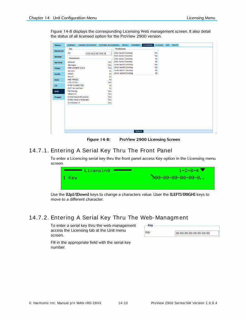
Chapter 14: Unit Configuration Menu Licensing Menu
© Harmonic Inc. Manual p/n MAN-IRD-29XX 14-10 ProView 2900 Series/SW Version 1.9.9.4
Figure 14-8 displays the corresponding Licensing Web management screen. It also detail the status of all licensed option for the ProView 2900 version.
Figure 14-8: ProView 2900 Licensing Screen
14.7.1. Entering A Serial Key Thru The Front Panel To enter a Licencing serial key thru the front panel access Key option in the Licensing menu screen.
Licensing 1-2-8-4
1 Key 00-00-00-00-00-0..
Use the [Up]/[Down] keys to change a characters value. User the [LEFT]/[RIGH] keys to move to a different character.
14.7.2. Entering A Serial Key Thru The Web-Managment To enter a serial key thru the web-management access the Licensing tab at the Unit menu screen.
Fill in the appropriate field with the serial key number.

Chapter 14: Unit Configuration Menu Dry Contact Menu
© Harmonic Inc. Manual p/n MAN-IRD-29XX 14-11 ProView 2900 Series/SW Version 1.9.9.4
14.8. Dry Contact Menu The Dry Contact menu screen allows configuring the GPI 1 or GPI 2. The GPI (General Purpose Interface) is a dry contact relay, used by the ProView 2900 for displaying warnings that appear in the device.
To access the Dry Contact through the front panel, go to: RootConfigurationUnitDry ContactGPI 1 (or GPI 2).
The GPI 1 and GPI 2 configuration menus are identical.
The following is the GPI 1 Edit Menu screen:
GPI 1 1-2-8-5-1
1 Delay 000.0[sec]
2 Sync Loss OFF
3 HW Failure OFF
4 Invalid PSI OFF
5 TS Buffer Overflow 5 OFF
6 TS Error 5 OFF
7 Continuity Counter 5 OFF
8 CRC Error 5 OFF
9 PRC Discontinuity 5 OFF
10 Decoder Buffer Overflow 5 OFF
11 Decoder Buffer Underflow 5 OFF
12 Decoder Stream Error 5 OFF
13 Test 5 OFF
The following details the Dry Contact warnings:
14.8.1. Delay The Delay screen allows setting a delay time for the GPI warnings.
Delay
000.0 [sec]
<000.0-600.0>
The Delay time rages from 0 to 600 seconds.

Chapter 14: Unit Configuration Menu Dry Contact Menu
© Harmonic Inc. Manual p/n MAN-IRD-29XX 14-12 ProView 2900 Series/SW Version 1.9.9.4
14.8.2. Sync Loss The Sync Loss menu defines whether or not a Sync Loss warning will cause a GPI warning indication.
Sync Loss
1 OFF
2 ON
The available options are:
• OFF – Sync Loss GPI warning indication is turned off
• ON – Sync Loss GPI warning indication is turned on
14.8.3. HW Failure The HW Failure menu defines whether or not a Hardware Failure warning will cause a GPI warning indication.
HW Failure
1 OFF
2 ON
The available options are ON and OFF:
14.8.4. Invalid PSI The Invalid PSI menu defines whether or not an Invalid PSI warning will cause a GPI warning indication.
Invalid PSI
1 OFF
2 ON
The available options are ON and OFF:
14.8.5. TS Buffer Overflow The TS Buffer Overflow menu defines whether or not to activate a GPI warning indication in case of the TS counter reaches the threshold for transport stream overflow.
TS Buffer Overflow
1 OFF
2 ON
The available options are ON and OFF:

Chapter 14: Unit Configuration Menu Dry Contact Menu
© Harmonic Inc. Manual p/n MAN-IRD-29XX 14-13 ProView 2900 Series/SW Version 1.9.9.4
14.8.6. TS Error The TS Error menu defines whether or not to activate a GPI warning indication in case of the TS counter reaches the threshold for transport stream error.
TS Error
1 OFF
2 ON
The available options are ON and OFF:
14.8.7. Continuity Counter The Continuity Counter menu defines whether or not to activate a GPI warning indication in case of the TS counter reaches the threshold for transport stream continuity error.
Continuity Counter
1 OFF
2 ON
The available options are ON and OFF:
14.8.8. CRC Error The CRC Error menu defines whether or not to activate a GPI warning indication in case of the TS counter reaches the threshold for CRC error.
CRC Error
1 OFF
2 ON
The available options are ON and OFF:
14.8.9. PRC Discontinuity The PRC Discontinuity menu defines whether or not to activate a GPI warning indication in case of the TS counter reaches the threshold for PRC Discontinuity error.
PRC Continuity
1 OFF
2 ON
The available options are ON and OFF:

Chapter 14: Unit Configuration Menu Dry Contact Menu
© Harmonic Inc. Manual p/n MAN-IRD-29XX 14-14 ProView 2900 Series/SW Version 1.9.9.4
14.8.10. Decoder Buffer Overflow The Decoder Buffer Overflow menu defines whether or not to activate a GPI warning indication in case of the unit counter reaches the threshold for decoder overflow.
Decoder Buffer Overflow
1 OFF
2 ON
The available options are ON and OFF:
14.8.11. Decoder Buffer Underflow The Decoder Buffer Underflow menu defines whether or not to activate a GPI warning indication in case of the unit counter reaches the threshold for decoder underflow.
Decoder Buffer Underflow
1 OFF
2 ON
The available options are ON and OFF:
14.8.12. Decoder Stream Error The Decoder Stream Error menu defines whether or not to activate a GPI warning indication in case of the unit counter reaches the threshold for decoder stream error.
Decoder Stream Error
1 OFF
2 ON
The available options are ON and OFF:
14.8.13. Test The Test menu allows operator to manually enable or disable the relevant GPI.
Test
1 OFF
2 ON
The available options are ON and OFF:

Chapter 14: Unit Configuration Menu Dry Contact Menu
© Harmonic Inc. Manual p/n MAN-IRD-29XX 14-15 ProView 2900 Series/SW Version 1.9.9.4
14.8.14. Dry Contact Configuration Using the Web-Interface Configuring the dry contact in the Web interface is divided to two different menus:
• Alarms – Allows enabling and disabling the alarms.
• GPI – Allows setting the GPI delay time and tests.
To access the Dry Contact (Alarms) configurations though the web-interface, go to: UnitAlarms. Figure 14-9 displays the Alarms web-interface screen:
Figure 14-9: Alarms Web-Interface Screen
NOTE
GPI1, GPI2, and the SNMP alarm can be enabled or disabled for every alarm. However once the Alarm Mask is disabled then also GPI1 and GPI2 are disabled.
To access the Dry Contact (General) configurations though the web-interface, go to: UnitGPI. Figure 14-10 displays the GPI web-interface screen:
Figure 14-10: GPI Web-Interface Screen

Chapter 14: Unit Configuration Menu Traps Menu (Web Manager Only)
© Harmonic Inc. Manual p/n MAN-IRD-29XX 14-16 ProView 2900 Series/SW Version 1.9.9.4
14.9. Traps Menu (Web Manager Only) Traps are notifications sent by the device without user intervention. The Traps Menu allows setting up to 5 trap destinations.
NOTE
Trap configuration is available through the Web-Management Interface and CLI.
This manual details trap configuration using the Web Management.
To access the Traps menu thought the web-interface, go to: UnitTraps. Figure 14-11 shows the web-interface Traps screen:
Figure 14-11: Web Interface – Traps Screen
The Traps screen displays two tables:
• Trap Destination Table, which includes the following columns: IP Address – Sets the IP address of the trap destination.
Port – Sets the UDP port number of the tarp destination.
Description – Optional parameter. Displays a string describing the trap destination.
Community String – Optional parameter. Displays a string describing the community of the
trap. This string is included in the trap message.
• Traps Masking Table, which allows setting preferences for each trap shown in the trap destination table. The Traps Masking Table includes the following parameters: Select Traps - allows selecting one of the shown in the trap destination table.
Mask For Trap – Shows the alarm's IP address and it's port.
Configuration Parameters: Allows enabling or disabling each of the following MIB parameters:
GoingToReboot, AlarmOn, AlarmOff, SettingChangess, ModuleInserted, and ModuleRemoved.
For details refer to the ProView 2900 MIB User Guidelines.

Chapter 14: Unit Configuration Menu Traps Menu (Web Manager Only)
© Harmonic Inc. Manual p/n MAN-IRD-29XX 14-17 ProView 2900 Series/SW Version 1.9.9.4
The following describe managing the Trap Destination:
To add a new Trap Destination:
1. Access the Traps tab. From the web-interface, go to: UnitTraps.
2. In the Trap Table, type valid values for the IP Address, Port, Description (optional) and Community String (optional) parameters. For example see Figure 14-12.
Figure 14-12: Add New Trap Destination
3. Click ADD.
To drop a Trap Destination:
1. Access the Traps tab. From the web-interface, go to: UnitTraps.
2. Click the Delete button located right to the trap entry. For example see Figure 14-13.
Figure 14-13: Delete Trap Destination
To modify a Trap Destination:
1. Access the Traps tab. From the web-interface, go to: UnitTraps.
2. Change the Trap entry parameters.
2. Click the Apply button located right to the trap entry. For example see Figure 14-14.
Figure 14-14: Modify Trap Destination
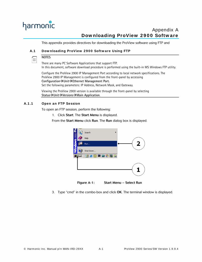
© Harmonic Inc. Manual p/n MAN-IRD-29XX A-1 ProView 2900 Series/SW Version 1.9.9.4
Appendix A Downloading ProView 2900 Software
This appendix provides directives for downloading the ProView software using FTP and
A.1 Downloading ProView 2900 Software Using FTP
NOTES
There are many PC Software Applications that support FTP. In this document, software download procedure is performed using the built-in MS Windows FTP utility.
Configure the ProView 2900 IP Management Port according to local network specifications. The ProView 2900 IP Management is configured from the front-panel by accessing ConfigurationUnitEthernet Management Port. Set the following parameters: IP Address, Network Mask, and Gateway.
Viewing the ProView 2900 version is available through the front-panel by selecting StatusUnitVersionsMain Application.
A.1.1 Open an FTP Session
To open an FTP session, perform the following:
1. Click Start. The Start Menu is displayed.
From the Start Menu click Run. The Run dialog box is displayed.
Figure A-1: Start Menu – Select Run
3. Type “cmd” in the combo-box and click OK. The terminal window is displayed.

Appendix A: Software Download
© Harmonic Inc. Manual p/n MAN-IRD-29XX A-2 ProView 2900 Series/SW Version 1.9.9.4
Figure A-2: Run Dialog Box
4. Type “ftp <ProView 2900 Management IP address>” and press [Enter]. FTP session is displayed. See the following example.
Figure A-3: Open FTP Session

Appendix A: Software Download
© Harmonic Inc. Manual p/n MAN-IRD-29XX A-3 ProView 2900 Series/SW Version 1.9.9.4
A.1.2 Log On 1. Log on to the ProView 2900 with the user name and password, both are empty
for the ProView 2900.
2. Reply with [Enter] for both user and password requests.
Figure A-4: Login to FTP
3. After connecting to the ProView 2900 through FTP, type “bin” and Click [Enter].
Figure A-5: Access Bin Folder
A.1.3 Loading The File
To load a source file from a local PC to the ProView 2900:
1. Type put and click [Enter]
2. After Local File, type the file name with the suffix (Notice - the software file name and path in the PC should be known).

Appendix A: Software Download
© Harmonic Inc. Manual p/n MAN-IRD-29XX A-4 ProView 2900 Series/SW Version 1.9.9.4
3. After Remote File, type ‘/rom/sw_image.bin’.
Figure A-6: Loading the File
After confirmation, the ProView 2900 progress is displayed in a loading screen on the ProView 2900 front-panel. In the left frame window the loading progress is indicated by a percentage and blinking progress bar. Following is the ProView 2900 loading screen:
NOTE
If the ProView 2900 is, for any reason, shut down during Software Download, the program must be reinstalled through Boot Software Download. Reinstallation is available through RS-232. See Section A.2.5.
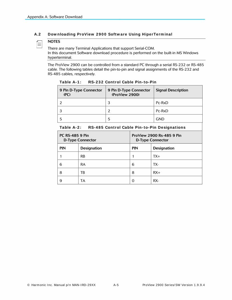
Appendix A: Software Download
© Harmonic Inc. Manual p/n MAN-IRD-29XX A-5 ProView 2900 Series/SW Version 1.9.9.4
A.2 Downloading ProView 2900 Software Using HiperTerminal
NOTES
There are many Terminal Applications that support Serial-COM. In this document Software download procedure is performed on the built-in MS Windows hyperterminal.
The ProView 2900 can be controlled from a standard PC through a serial RS-232 or RS-485 cable. The following tables detail the pin-to-pin and signal assignments of the RS-232 and RS-485 cables, respectively.
Table A-1: RS-232 Control Cable Pin-to-Pin
9 Pin D-Type Connector (PC)
9 Pin D-Type Connector (ProView 2900)
Signal Description
2 3 Pc-RxD
3 2 Pc-RxD
5 5 GND
Table A-2: RS-485 Control Cable Pin-to-Pin Designations
PC RS-485 9 Pin D-Type Connector
ProView 2900 Rs-485 9 Pin D-Type Connector
PIN Designation PIN Designation
1 RB 1 TX+
6 RA 6 TX-
8 TB 8 RX+
9 TA 0 RX-

Appendix A: Software Download
© Harmonic Inc. Manual p/n MAN-IRD-29XX A-6 ProView 2900 Series/SW Version 1.9.9.4
A.2.1 Opening Hyperterminal from MS Windows 1. Access HyperTerminal application, by selecting
StartProgramAccessoriesCommunicationHyperTerminal
Figure A-7: Start Menu – Open HyperTerminal
A.2.2 Defining the Communication
When the HyperTerminal starts, the following window is displayed.
1. Enter a connection, for example ProView 29000 and lick OK.
2. Select a connection (Icon).
Figure A-8: HyperTerminal – Enter Connection
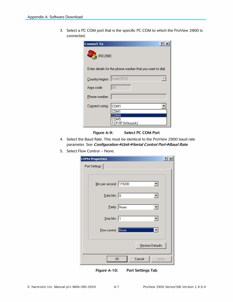
Appendix A: Software Download
© Harmonic Inc. Manual p/n MAN-IRD-29XX A-7 ProView 2900 Series/SW Version 1.9.9.4
3. Select a PC COM port that is the specific PC COM to which the ProView 2900 is connected.
Figure A-9: Select PC COM Port
4. Select the Baud Rate. This must be identical to the ProView 2900 baud rate parameter. See ConfigurationUnitSerial Control PortBaud Rate.
5. Select Flow Control – None.
Figure A-10: Port Settings Tab
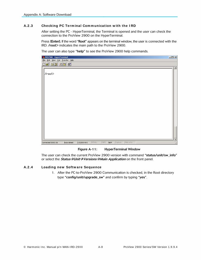
Appendix A: Software Download
© Harmonic Inc. Manual p/n MAN-IRD-29XX A-8 ProView 2900 Series/SW Version 1.9.9.4
A.2.3 Checking PC Terminal Communication with the IRD
After setting the PC - HyperTerminal, the Terminal is opened and the user can check the connection to the ProView 2900 on the HyperTerminal.
Press [Enter]. If the word “Root” appears on the terminal window, the user is connected with the IRD. /root> indicates the main path to the ProView 2900.
The user can also type “help” to see the ProView 2900 help commands.
Figure A-11: HyperTerminal Window
The user can check the current ProView 2900 version with command “status/unit/sw_info” or select the StatusUnitVersionsMain Application on the front panel.
A.2.4 Loading new Software Sequence 1. After the PC-to-ProView 2900 Communication is checked, in the Root directory
type “config/unit/upgrade_sw” and confirm by typing “yes”.
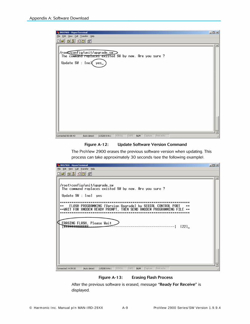
Appendix A: Software Download
© Harmonic Inc. Manual p/n MAN-IRD-29XX A-9 ProView 2900 Series/SW Version 1.9.9.4
Figure A-12: Update Software Version Command
The ProView 2900 erases the previous software version when updating. This process can take approximately 30 seconds (see the following example).
Figure A-13: Erasing Flash Process
After the previous software is erased, message “Ready For Receive” is displayed.
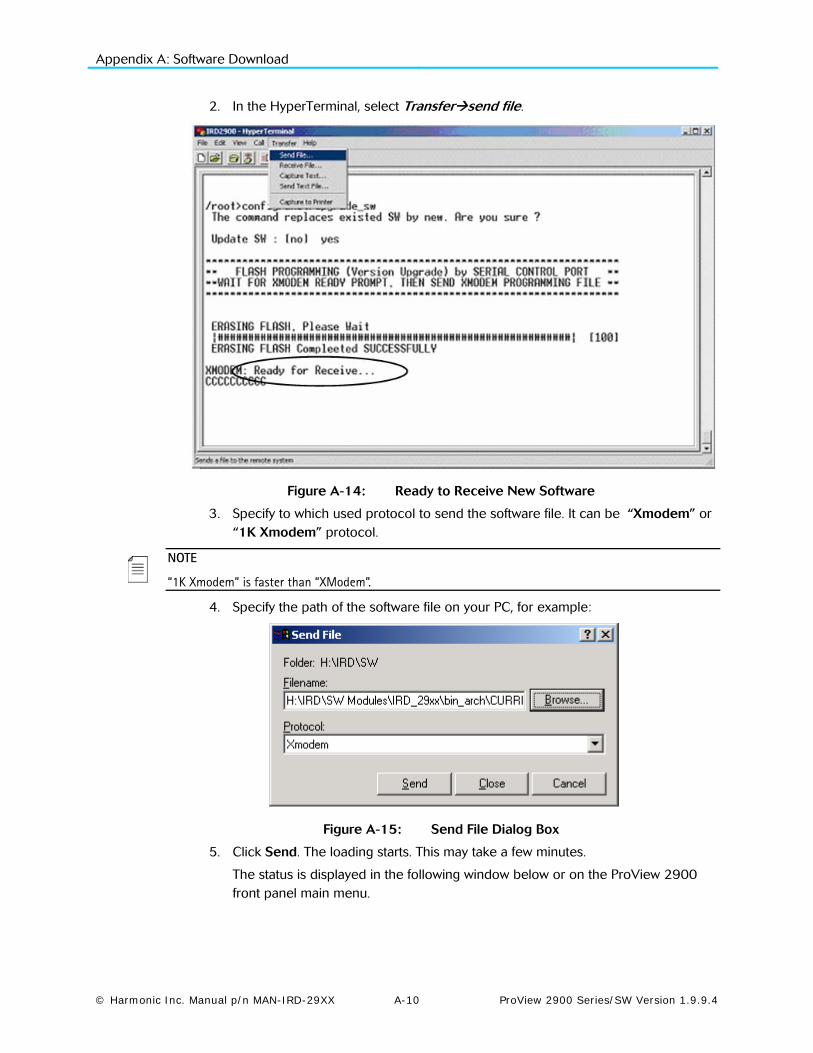
Appendix A: Software Download
© Harmonic Inc. Manual p/n MAN-IRD-29XX A-10 ProView 2900 Series/SW Version 1.9.9.4
2. In the HyperTerminal, select Transfersend file.
Figure A-14: Ready to Receive New Software
3. Specify to which used protocol to send the software file. It can be “Xmodem” or “1K Xmodem” protocol.
NOTE
“1K Xmodem” is faster than “XModem”.
4. Specify the path of the software file on your PC, for example:
Figure A-15: Send File Dialog Box
5. Click Send. The loading starts. This may take a few minutes.
The status is displayed in the following window below or on the ProView 2900 front panel main menu.

Appendix A: Software Download
© Harmonic Inc. Manual p/n MAN-IRD-29XX A-11 ProView 2900 Series/SW Version 1.9.9.4
Figure A-16: Sending Status Dialog Box
When the process is complete, a confirmation is displayed, indicating that the file was loaded. Then the ProView 2900 performs reboot.
6. Wait until the ProView 2900 is finished rebooting the new software.
7. On the front panel, verify that the new version is installed.
A.2.5 Loading Software Version through ProView 2900 BOOT Application
When the ProView 2900 is shut down during software download, the ProView 2900 start up sequence is set with the boot application. Perform the following:
1. Stop the previous Hyper Terminal sending process and restart standard communication with the ProView 2900.
2. When the ProView 2900 starts the BOOT application, the following hyperterminal window is displayed.
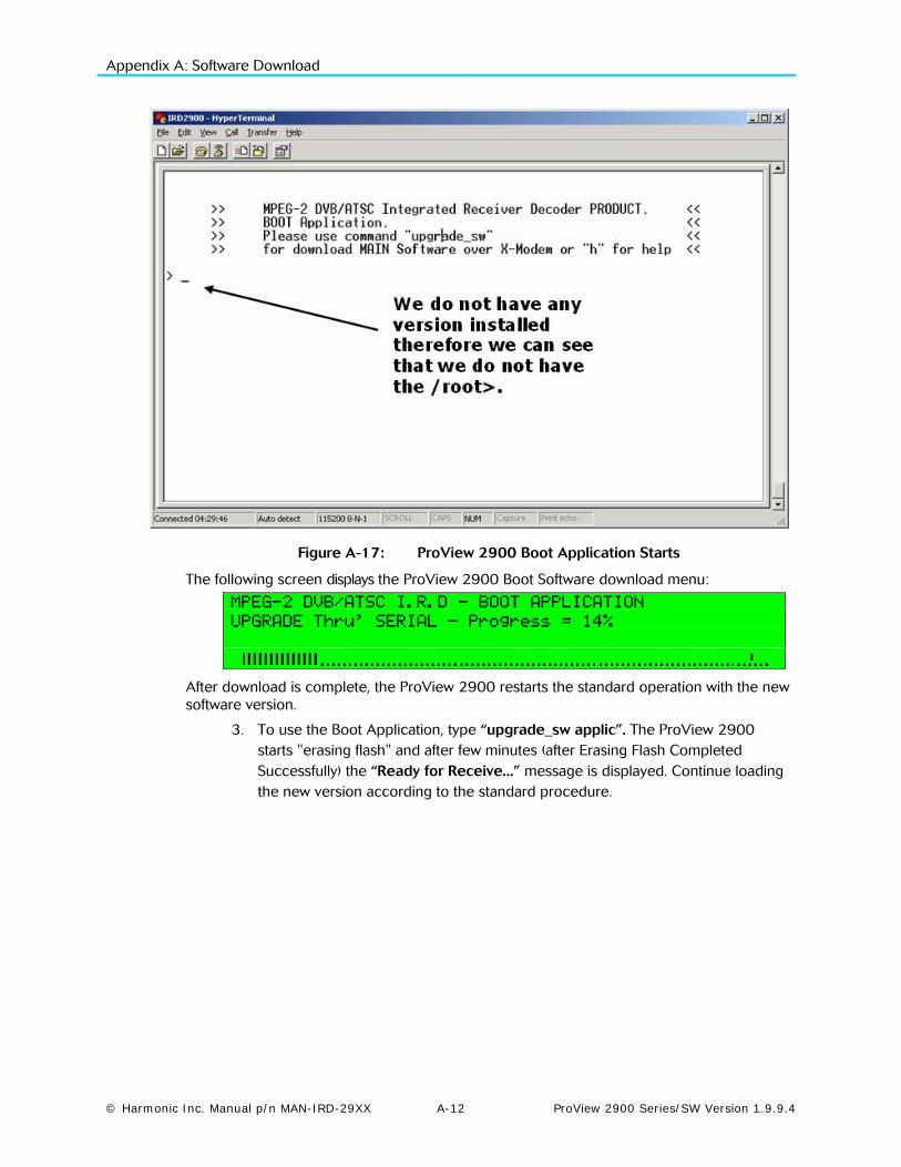
Appendix A: Software Download
© Harmonic Inc. Manual p/n MAN-IRD-29XX A-12 ProView 2900 Series/SW Version 1.9.9.4
Figure A-17: ProView 2900 Boot Application Starts
The following screen displays the ProView 2900 Boot Software download menu:
MPEG-2 DVB/ATSC I.R.D - BOOT APPLICATION
UPGRADE Thru’ SERIAL - Progress = 14%
After download is complete, the ProView 2900 restarts the standard operation with the new software version.
3. To use the Boot Application, type “upgrade_sw applic”. The ProView 2900 starts "erasing flash" and after few minutes (after Erasing Flash Completed Successfully) the “Ready for Receive...” message is displayed. Continue loading the new version according to the standard procedure.
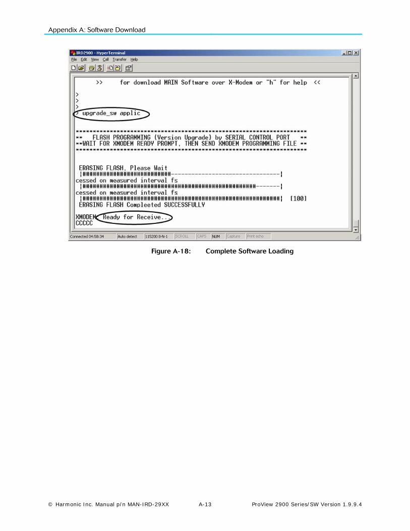
Appendix A: Software Download
© Harmonic Inc. Manual p/n MAN-IRD-29XX A-13 ProView 2900 Series/SW Version 1.9.9.4
Figure A-18: Complete Software Loading

© Harmonic Inc. Manual p/n MAN-IRD-29XX B-1 ProView 2900 Series/SW Version 1.9.9.4
Appendix B IP-Front End Software Upgrade Procedure
This appendix details the software upgrade procedure in an IP front end ProView 2900 device. This procedure is different than in other front end devices.
To run the IP Front End software upgrade, perform the following steps:
1. The watchdog feature must first be disabled in the ProView 2900 for correct SW upgrade. To disable the watchdog feature, perform the following steps:
• In the ProView 2900 front panel, go to Configuration StreamSource and select Serial RS422
• In the command prompt (StartRun) on the PC enter ’telnet <device IP address> 1023.
NOTE:
To obtain the <device IP address> in the ProView 2900 front panel, go to ConfigurationReceiverMPEGoIP Input 1 (or 2)Physical Link and copy the number from the IP Address parameter.
• In the Telnet prompt, press Enter. • In the Telnet prompt, type 'dwd'. • Power off the ProView 2900 • After a few seconds, power on the ProView 2900. The watchdog function is
now off.
2. For each new SW upgrade, obtain a self extracting software upgrade file.
3. Create a new directory under drive C:\ and name it NEW_VER.
4. Copy the self extracting file into the NEW_VER directory.
5. Go to StartRun and enter ‘cmd’.
6. In the command prompt window enter ‘cd \NEW_VER’.
7. Type the name of the SW upgrade self-extracting EXE file and press Enter
8. Answer any questions that may be displayed on the command prompt window with ‘Y’ followed by Enter
9. After the self extracting file has finished the self extraction, run the file called ‘update.bat’ from this same directory, then enter the ProView 2900 IP address. Obtain the IP address by accessing ConfigurationReceiverMPEGoIP Input 1 (or 2)Physical Link in the front panel. Then copy the address from the IP Address parameter. For example ‘update 10.100.1.26’.
10. In the Telnet prompt window, type ‘telnet <unit IP Address> 1023’ (use the same IP Address as in step 9).
11. Type 'exit' and then Enter.
12. Type ' burn “vxw” ' and then Enter.
13. Type ' “burn “ird” ' and then Enter.
14. Power off the ProView 2900.

Appendix B: IP Front-End SW Update
© Harmonic Inc. Manual p/n MAN-IRD-29XX B-2 ProView 2900 Series/SW Version 1.9.9.4
15. After a few seconds, power on the ProView 2900.
16. On the ProView 2900 front panel, go to Configuration StreamSource and select FRONT END (IP)
17. Verify the correct upgrading of the new SW version by going in the ProView 2900 front panel to StatusReceiverGeneral and checking the SW Version dd/mm/yy mj.mn parameter value
NOTE
If power failure occurs during upgrade, repeat the upgrade from step 1

© Harmonic Inc. Manual p/n MAN-IRD-29XX C-1 ProView 2900 Series/SW Version 1.9.9.4
Appendix C Aspect Ratio Configuration Process
This Appendix details ProView 2900 configuring for the fitting of Aspect Ratio (A/R) of the incoming Video to the A/R of the destination monitor.
C.1 Aspect Ratio Conversion Machine
The ProView 2900 provides the ability, using interpolation, to produce different image formats, enabling the display of the incoming Video on either a 4:3 or a 16:9 monitor.
16:9 Video Streams can be fitted for display on 4:3 monitors, and vice versa, in more than one format, as summarized in Table C-1 and Table C-2.
A/R fitting is referred to as Conversion. The ProView 2900 contains an “Aspect Ratio Conversion Machine” responsible for all image conversions.
Figure C-1 displays a simplified illustration of this machine.
Figure C-1: Aspect Ratio Conversion Machine
When fitting the received Video signal A/R to the monitor A/R, the following three ProView 2900 parameters values must be set to achieve the required conversion:
• WSS
• Monitor Aspect Ratio
• Interpolation
C.1.1 WSS (Wide Screen Signaling)
The purpose of the WSS signal is to inform the destination monitor of the received Video A/R. The ProView 2900 extracts the WSS information from an operator-selected source, generates a new WSS signal (see ‘WSS Signal Generator’ in Figure C-1), and outputs it to the monitor.
The WSS menu in the ProView 2900 contains two items (see WSS explanation in Section 9.3 for further details):
Source – from which the ProView 2900 extracts the WSS information. The available options
are: DISABLE, TV MONITOR, E.S. (EN-301-775), and VIDEO.

Appendix C: Aspect ratio Configuration
© Harmonic Inc. Manual p/n MAN-IRD-29XX C-2 ProView 2900 Series/SW Version 1.9.9.4
Line1 – Video line into which the ProView 2900 inserts the generated WSS signal (see WSS
explanation in Section 9.3 for further details).
C.1.2 Monitor Aspect Ratio
This parameter informs the Conversion Machine of the destination monitor’s A/R. This is one of two parameter values which the Conversion Machine needs for its operation (see Figure C-1).
The available options are: VIDEO SOURCE, 16:9, 16:9 BOX, and 4:3 (see Monitor Aspect Ratio explanation in Section 9.2 for further details).
C.1.3 Interpolation
This parameter sets the method of interpolation which the Conversion Machine will use when converting the Video Stream.
C.2 Table of Conversions
After setting the values of WSS, Monitor Aspect Ratio, and Interpolation, the ProView 2900 receives all required A/R information for re-creating the image.
Table C-1 and Table C-2 details the format of the image after conversion in all ProView 2900 available settings combinations, and depending upon the incoming signal's A/R.
The resulting image is affected by the combination of four variables displayed in the A/R Conversion Table:
• The actual Video Stream A/R (Stream column)
• Destination Monitor A/R (Monitor Column)
• Interpolation value, set in the Conversion Machine (Interpolation Column)
• Monitor Aspect Ratio value, set in the Conversion Machine (WSS Column)
The following Video Bar figures are used in the table to demonstrate the image format changes.
Figure C-2 illustrates a normal 4:3 Video image
Figure C-2: Normal 4:3 Aspect Ratio
Figure C-3 illustrates a normal 16:9 Video image

Appendix C: Aspect ratio Configuration
© Harmonic Inc. Manual p/n MAN-IRD-29XX C-3 ProView 2900 Series/SW Version 1.9.9.4
Figure C-3: Normal 16:9 Aspect Ratio
Table C-1: Table of Conversions - 4:3 Stream Option
Stream 4:3
Monitor 16:9 or
4:3
Interpolation Pan Scan or
Letter Box
WSS TV Monitor or
Video Stream
Output Description Conversion is not available.
Always displays Normal picture on 4:3 TV and short and fat on the 16:9 TV
WSS – 4:3 Full Format 0001.0000.000.000
Can be output if WSS is set as Video Stream
Output Display 4:3
16:9

Appendix C: Aspect ratio Configuration
© Harmonic Inc. Manual p/n MAN-IRD-29XX C-4 ProView 2900 Series/SW Version 1.9.9.4
Table C-2: Table of Conversions - 16:9 Options
Stream 16:9 16:9 16:9
Monitor 16:9 4:3 4:3
Interpolation Pan Scan Pan Scan Letter Box
WSS TV Monitor or
Video Stream
TV Monitor or
Video Stream
TV Monitor or
Video Stream
Output Description
• No conversion • Always displays
Normal picture on 16:9 and tall and thin on the 4:3 TV
WSS –
• 16:9 Full Format 1110.0000.00.000 Can be output if WSS is set as Video Stream
• Conversion horizontally up-samples the central portion of the picture to fill the 720
WSS –
• 4:3 Full Format 0001.0000.000.000 Can be output if WSS is set as Monitor.
• 16:9 Full Format 1110.0000.000.000 can be output if WSS is set as Video Stream
• Conversion vertically down-stamps the picture and applies black bar to the top and bottom of the screen
WSS –
• 4:3 Full Format 0001.0000.000.000can be output if WSS is set as Monitor
• 16:9 Letter Box 1101.0000.000.000can be output is WSS is set as Video Stream
NOTE
With 16:9 L/B signalling as auto sense, 16:9 monitor can convert the picture to Normal 16:9
Output Display 4:3
16:9
4:3
16:9
4:3
16:9
© Harmonic Inc. Manual p/n MAN-IRD-29XX D-1 ProView 2900 Series/SW Version 1.9.9.4
Appendix D ProView 2900 Configuration File
This Appendix summarizes the content of the ProView 2900 configuration file.
The configuration file is mostly used for configuration backup and for redundancy application. The configuration file is uploaded and downloaded through the FTP.
The ProView 2900 Configuration file holds parameters regarding the following:
• Stream Configurations – see section D.1.
• Service Configurations – see section D.2.
• Video Configurations – see section D.3.
• Audio Configurations – see section D.4.
• Data Configurations – see section D.5.
• DVB S Receiver Configurations – see section D.6.
• IP Receiver Configurations – see section D.7.
D.1 Stream Configurations
The ProView 2900 Configuration file holds the following Stream parameters:
• Stream Type
• Stream Rate Range
• ASI Mode
• ASI Output Type
• IP Output Type
• 27MHz Synchronization
D.2 Service Configurations
The ProView 2900 Configuration file holds the following Service parameters:
• TV1 Select
• TV2 Select
• Stand alone select
• Preferred languages (Audio 1-4, VBI 1-2, Subtitling 1-2).
• PID Select (PCR 1-2, Video 1-2, Audio 1-4, VBI 1-2, Subtitling 1-2, LS Data RS232, HS Data RS422)
• Mapping port to service (PCR 1-2, Video 1-2, Audio 1-4, VBI 1-2, Subtitling 1-2, LS Data RS232, HS Data RS422, General Configuraion , Service strategy , Service CAS open)

Appendix D: ProView 2900 Configuration File
© Harmonic Inc. Manual p/n MAN-IRD-29XX D-2 ProView 2900 Series/SW Version 1.9.9.4
D.3 Video Configurations
The ProView 2900 Configuration file holds the following Video parameters:
• Video 1/ Video 2 (Format, , Interpolation, Monitor aspect ratio, Lip-Sync mode, STC-PCR delay, Blanking mode)
• VBI 1/ VBI 2 (CC, , AMOL, VITS, VITC, WSS, TTX, , VPS, SMC, OSD 1/ OSD 2, Monitor output, Brodcast output, X position offset, Y position offset, DVB Subtitlte mode, TXT subtitle mode)
D.4 Audio Configurations
The ProView 2900 Configuration file holds the following Audio parameters:
• Audio number
• Decoder Mode
• AC3 downmix mode
• AC3 operational
• Pass Through sample rate
• Volume
• Analog output
• Analog mixer
• Digital mixer
D.5 Data Configurations
The ProView 2900 Configuration file holds the following Data parameters:
• Operational mode
• Protocol
• Destination IP address
• UDP source port
• UDP destination port
• Number of packets
D.6 DVB S Receiver Configurations
The ProView 2900 Configuration file holds the following DVB-S Receiver parameters:
• Frequency
• Symbol rate
• FEC rate
• Spectral inversion
• LNB power supply
• LNB 22 KHz
• Frequency drift compensation
• LNB L.O. Type
• Frequency Range
• Frequency Band Scan

Appendix D: ProView 2900 Configuration File
© Harmonic Inc. Manual p/n MAN-IRD-29XX D-3 ProView 2900 Series/SW Version 1.9.9.4
D.7 IP Receiver Configuration
The ProView 2900 Configuration file holds the following IP Receiver parameters:
• MPEGoIP1/ MPEGoIP2 (Logical source , IP address type, IP multicast address , UDP destination port, FEC Colum port)
• General (Selected active Port, Redundancy enable/disable, Redundancy Delay, De-Jitter Delay, FEC enable/disable)

© Harmonic Inc. Manual p/n MAN-IRD-29XX E-1 ProView 2900 Series/SW Version 1.9.9.4
Appendix E ProView 2900 Warning Messages
This Appendix details all error notifications available for the ProView 2900. Errors can be caused by ether hardware or software malfunctions. An error is indicated by the Warning Leds located right to the front panel screen, followed by an Error Message on the front panel screen.
E.1 Warning LEDs
The ProView 2900 provided with two warning LEDs located right to the front panel screen. These LEDs indicate errors when detected. Figure E-1 shows the warning LEDs as located on the front panel.
Figure E-1: Front Panel Warning LEDs
The available LEDs are:
• WARNING – indicates any detected error by an orange light.
• PWR/FAIL – indicates hardware errors by a red light.
When the ProView 2900 is properly functioning, both LEDs light green.
E.2 Warning messages
Warning messages appears on the front panel screen when an error is detected. The warning message briefly describes the level of the malfunction.
Satellite front-end warnings:
• Signal Not Received
• Demodulator Not Sync
• Viterbi Not Sync
• Deinterleaver Not Sync
• Front End Not Locked
IP front-end warnings:
• IP Config' Error
Satellite/IP bit-stream warnings:
• No Sync-0x47 Detected
• PSI Not Detected

Harmonic Inc. 4300 North First St. San Jose, CA 95134, U.S.A. T +1 408 542 2500 F +1 408 490 6770
www.harmonicinc.com © Copyright 2012 Harmonic Inc. All rights reserved