proview 7000 v.2.6 user guide - digitalglue · proview 7000 multifunctional receiver user guide...
TRANSCRIPT

ProView 7000Multifunctional Receiver
User GuideVERSION 2.6
Rev. A
Manual Part No. MAN-PVR-7K-2.6

© 2012 Harmonic Inc. All rights reserved.
Disclaimer
Harmonic reserves the right to alter the equipment specifications and descriptions in this publication without prior notice. No part of this publication shall be deemed to be part of any contract or warranty unless specifically incorporated by reference into such contract or warranty. The information contained herein is merely descriptive in nature, and does not constitute a binding offer for sale of the product described herein. Harmonic assumes no responsibility or liability arising from the use of the products described herein, except as expressly agreed to in writing by Harmonic. The use and purchase of this product do not convey a license under any patent rights, copyrights, trademark rights, or any intellectual property rights of Harmonic. Nothing hereunder constitutes a representation or warranty that using any products in the manner described herein will not infringe any patents of third parties.
Trademark Acknowledgments
Harmonic and all Harmonic product names are trademarks of Harmonic Inc. All other trademarks are the property of their respective owners.
Compliance and Approval
This equipment generates, uses, and can radiate radio frequency energy. It may cause harmful interference to radio communications if it is not installed and used in accordance with the instructions in this manual. Operation of this equipment in a residential area is likely to cause harmful interference. If this occurs, the user will be required to correct the interference at his or her own expense.
This equipment has been tested and found to comply with the limits for a Class A digital device, pursuant to Part 15, Subpart B of the Federal Communications Commission (FCC) rules.
These limits are designed to provide reasonable protection against harmful interference when the equipment is operated in a commercial environment.
This device complies with Part 15 of the FCC rules. Operation is subject to the following two conditions: (1) this device may not cause harmful interference, and (2) this device must accept any interference received, including interference that may cause undesired operation.
Connections between the Harmonic equipment and other equipment must be made in a manner that is consistent with maintaining compliance with FCC radio frequency emission limits. Modifications to this equipment not expressly approved by Harmonic may void the authority granted to the user by the FCC to operate this equipment.
WEEE/RoHS Compliance Policy
Harmonic Inc. intends to comply fully with the European Union’s Directive 2002/96/EC as amended, on Waste Electrical and Electronic Equipment, also known as “WEEE,” and Directive 2002/95/EC, as amended, on the Restriction of use of Hazardous Substances, also known as “RoHS.”
Harmonic will ensure that product which cannot be reused will be recycled in compliance with the WEEE Directive. To that end, users are advised that (1) Harmonic equipment is not to be discarded in household or office garbage, (2) Harmonic Inc. will pay the freight for shipment of equipment to be disposed of if it is returned to Harmonic, (3) customers should call the normal RMA telephone numbers to arrange for such shipment, and (4) for additional and updated information on this process customers may consult the Harmonic website: http://harmonicinc.com/pa_weee_recycle.cfm.
Harmonic will ensure that its products will be either reused or recycled in compliance with the WEEE Directive. For the latest information concerning Harmonic’s WEEE/RoHS Compliance Policy and its Recycling and Take-Back process, please visit our web site.

© 2012 Harmonic Inc. All rights reserved.
产品中的有毒有害物质或元素的名称及含量表 Names and Contents of the Toxic and Hazardous Substances or Elements in the Products if the Part is Present
该表显示哈雷公司产品中可能含有的有毒有害物质元配件的信息,除了来源于元配件供应商的物料成分资料, 亦来自其它相关的机构与资料。哈雷产品不一定使用这些元配件。This table shows those components where hazardous substances may be found in Harmonic products based on, among other things, material content information provided by third party suppliers. These components may or may not be part of the product.
除非特殊注明,哈雷公司产品的环保使用期限 均为 20 年。该环保使用期限的有效条件为:必须遵循该产品使用手册的规定,对该产品进行使用或存储。The Environmental Protective Use Period for Harmonic products is 20 years unless displayed otherwise on the product. The EPUP period is valid only when the products are operated or stored as per the conditions specified in the product manual.
O: 表示在该部件的所有均质材料中,此类有毒有害物质的含量均小于 SJ/T11363-2006 标准所规定的限量。
O: Indicates the content of the toxic and hazardous substances at the homogeneous material level of the parts is below the limit defined in SJ/T11363 2006 standard.
X: 表示至少在该部件的某一均质材料中,此类有毒有害物质的含量超出 SJ/T11363-2006 标准规定的限量。
X: Indicates that the content of the toxic and hazardous substances in at least one of the homogeneous materials of the parts is above the limit defined in SJ/T11363 2006 standard.
部件名称 (Part name)
有毒有害物质或元素 (Hazardous Substance)
铅(PB)
汞(Hg)
镉(Cd)
六价铬(CrVI)
多溴联苯(PBB)
多溴二苯醚(PBDE)
印刷线路板 (Printed Circuit Assemblies)
X O O O O O
机械组件 (Mechanical Subassemblies)
X O O O O O
光学组件 (Optical Subassemblies)
X O O O O O
电源 (Power Supplies) X O O O O O
缆线 / 线束 (Cables, harnesses)
X O O O O O
屏幕 / 显示器 (Screens, Monitors)
X O O O O O
金属零件 (Metal Parts)
O O O O O O
塑料 / 发泡材料 (Plastics, foams) O O O O O O
电池 (Batteries)
X O O O O O

© 2012 Harmonic Inc. All rights reserved.
Standards and Agency Approval
The following tables list regulatory standards and agency approvals:
North America
Europe
Japan
Australia and New Zealand
Standards Agency Approval
EMI: FCC Part 15, Subpart B, ICES-003, Issue 2, Class A FCC
Safety: UL 60950-1, CSA 60950-1 cTUV-us Mark
Standards Agency Approval
EMI/EMC: EN55022, Class A, EN55024 CE
Safety: EN 60950-1, EN60825-1 TUV-GS or T-Mark, CE
Standards Agency Approval
EMI: VCCI V-3 2009 VCCI
Standards Agency Approval
EMI: AS/NZS CISPR22:2006 N/A

© 2012 Harmonic Inc. All rights reserved.
Documentation ConventionsThis manual uses some special symbols and fonts to call your attention to important information. The following symbols appear throughout this manual:
DANGER: The Danger symbol calls your attention to information that, if ignored, can cause physical harm to you.
CAUTION: The Caution symbol calls your attention to information that, if ignored, can adversely affect the performance of your Harmonic product, or that can make a procedure needlessly difficult.
LASER DANGER: The Laser symbol and the Danger alert call your attention to information about the lasers in this product that, if ignored, can cause physical harm to you.
NOTE: The Note symbol calls your attention to additional information that you will benefit from heeding. It may be used to call attention to an especially important piece of information you need, or it may provide additional information that applies in only some carefully delineated circumstances.
TIP: The Tip symbol calls your attention to parenthetical information that is not necessary for performing a given procedure, but which, if followed, might make the procedure or its subsequent steps easier, smoother, or more efficient.
In addition to these symbols, this manual uses the following text conventions:
NOTE: You require Adobe Reader or Adobe Acrobat version 6.0 or later to open the PDF files. You can download Adobe Reader free of charge from www.adobe.com.
Convention Explanation
Typed Command Indicates the text that you type in at the keyboard prompt.
Buttons and Menus Indicates a button to click, or a menu item to select.
<Ctrl>, <Ctrl>+<Shift> A key or key sequence to press.
Links The italics in blue text to indicate cross-references, and hyperlinked cross-references in online documents.
Bold Indicates a new term. For example:SpanWindow - the transmission frequency along the 1GHz spectrum allocated for each RF Port. It spans across 384MHz.
LCD Screen Output The text that is displayed on an LCD console output.
ScreenOutput The text that is displayed on a computer screen.
Emphasis The italics text used for emphasis and document references.

Table of Contents
© 2012 Harmonic Inc. 6 ProView 7000 v.2.6, Rev. A
Table of Contents
Chapter 1 Introduction1.1 General Information . . . . . . . . . . . . . . . . . . . . . . . . . . . . . . . . . . . . . . . . . . . . . . . . . 111.2 Main ProView 7000 Applications . . . . . . . . . . . . . . . . . . . . . . . . . . . . . . . . . . . . . . . 12
1.2.1 TS Descrambling Applications . . . . . . . . . . . . . . . . . . . . . . . . . . . . . . . . . . . . . . . . . 121.2.2 Decoding Applications . . . . . . . . . . . . . . . . . . . . . . . . . . . . . . . . . . . . . . . . . . . . . . . 12
1.3 ProView 7000 Platform Main Features and Configurations . . . . . . . . . . . . . . . . . 121.3.1 Multi-Transport Stream Descrambler . . . . . . . . . . . . . . . . . . . . . . . . . . . . . . . . . . . 131.3.2 Multi-Format Decoder . . . . . . . . . . . . . . . . . . . . . . . . . . . . . . . . . . . . . . . . . . . . . . . 141.3.3 DMS (Distribution Management System) . . . . . . . . . . . . . . . . . . . . . . . . . . . . . . . . 16
1.4 ProView 7000 Mechanical Structure . . . . . . . . . . . . . . . . . . . . . . . . . . . . . . . . . . . . 171.4.1 ProView 7000 Enclosure . . . . . . . . . . . . . . . . . . . . . . . . . . . . . . . . . . . . . . . . . . . . . . 171.4.2 ProView 7000 Front Panel . . . . . . . . . . . . . . . . . . . . . . . . . . . . . . . . . . . . . . . . . . . . 171.4.3 ProView 7000 Rear Panel . . . . . . . . . . . . . . . . . . . . . . . . . . . . . . . . . . . . . . . . . . . . . 17
1.5 ProView 7000 Management . . . . . . . . . . . . . . . . . . . . . . . . . . . . . . . . . . . . . . . . . . . 18
Chapter 2 Quick Start2.1 Installation and Cable Connection. . . . . . . . . . . . . . . . . . . . . . . . . . . . . . . . . . . . . . 19
2.1.1 Installation . . . . . . . . . . . . . . . . . . . . . . . . . . . . . . . . . . . . . . . . . . . . . . . . . . . . . . . . . 192.1.2 Electrical connection. . . . . . . . . . . . . . . . . . . . . . . . . . . . . . . . . . . . . . . . . . . . . . . . . 192.1.3 Cable Connections. . . . . . . . . . . . . . . . . . . . . . . . . . . . . . . . . . . . . . . . . . . . . . . . . . . 20
2.2 Switching On . . . . . . . . . . . . . . . . . . . . . . . . . . . . . . . . . . . . . . . . . . . . . . . . . . . . . . . 202.3 Configuring the IP Parameters . . . . . . . . . . . . . . . . . . . . . . . . . . . . . . . . . . . . . . . . . 202.4 Configuring and Monitoring. . . . . . . . . . . . . . . . . . . . . . . . . . . . . . . . . . . . . . . . . . . 21
2.4.1 A Typical ProView 7000 Configuration Using the Front Panel . . . . . . . . . . . . . . . 212.4.2 EMS Initial Setup. . . . . . . . . . . . . . . . . . . . . . . . . . . . . . . . . . . . . . . . . . . . . . . . . . . . 252.4.3 A Typical ProView 7000 Configuration Using EMS. . . . . . . . . . . . . . . . . . . . . . . . . 27
Chapter 3 Front Panel Overview3.1 Main Elements and Structure. . . . . . . . . . . . . . . . . . . . . . . . . . . . . . . . . . . . . . . . . . 323.2 Front Panel Display . . . . . . . . . . . . . . . . . . . . . . . . . . . . . . . . . . . . . . . . . . . . . . . . . . 33
3.2.1 Menu Pages . . . . . . . . . . . . . . . . . . . . . . . . . . . . . . . . . . . . . . . . . . . . . . . . . . . . . . . . 343.2.2 Parameter Pages . . . . . . . . . . . . . . . . . . . . . . . . . . . . . . . . . . . . . . . . . . . . . . . . . . . . 343.2.3 Edit Value Pages . . . . . . . . . . . . . . . . . . . . . . . . . . . . . . . . . . . . . . . . . . . . . . . . . . . . 353.2.4 Radio Select Pages . . . . . . . . . . . . . . . . . . . . . . . . . . . . . . . . . . . . . . . . . . . . . . . . . . 35
Chapter 4 Device Configuring Using the Front Panel4.1 Configuring the DVB-S/S2 Input Port Properties . . . . . . . . . . . . . . . . . . . . . . . . . . 364.2 Configuring the Decoding. . . . . . . . . . . . . . . . . . . . . . . . . . . . . . . . . . . . . . . . . . . . . 39
4.2.1 Service Selection Mode. . . . . . . . . . . . . . . . . . . . . . . . . . . . . . . . . . . . . . . . . . . . . . . 404.2.2 Video Configuration . . . . . . . . . . . . . . . . . . . . . . . . . . . . . . . . . . . . . . . . . . . . . . . . . 404.2.3 PCR Configuration . . . . . . . . . . . . . . . . . . . . . . . . . . . . . . . . . . . . . . . . . . . . . . . . . . . 424.2.4 Audio 1 / 2 Configuration . . . . . . . . . . . . . . . . . . . . . . . . . . . . . . . . . . . . . . . . . . . . . 434.2.5 VBI/VANC Configuration . . . . . . . . . . . . . . . . . . . . . . . . . . . . . . . . . . . . . . . . . . . . . . 44

Table of Contents
© 2012 Harmonic Inc. 7 ProView 7000 v.2.6, Rev. A
4.3 Routing and Descrambling . . . . . . . . . . . . . . . . . . . . . . . . . . . . . . . . . . . . . . . . . . . . 454.4 Configuring the GbE Ports, Sockets and Routing Table . . . . . . . . . . . . . . . . . . . . . 474.5 CA Definitions . . . . . . . . . . . . . . . . . . . . . . . . . . . . . . . . . . . . . . . . . . . . . . . . . . . . . . 50
4.5.1 BISS . . . . . . . . . . . . . . . . . . . . . . . . . . . . . . . . . . . . . . . . . . . . . . . . . . . . . . . . . . . . . . 504.5.2 CAM 1/2 Sub Menu. . . . . . . . . . . . . . . . . . . . . . . . . . . . . . . . . . . . . . . . . . . . . . . . . . 504.5.3 CAM Association . . . . . . . . . . . . . . . . . . . . . . . . . . . . . . . . . . . . . . . . . . . . . . . . . . . . 504.5.4 Selecting All Elementary Streams . . . . . . . . . . . . . . . . . . . . . . . . . . . . . . . . . . . . . . 504.5.5 Configuring Only Relevant Elementary Streams . . . . . . . . . . . . . . . . . . . . . . . . . . . 514.5.6 Accessing the CAM MMI Menu . . . . . . . . . . . . . . . . . . . . . . . . . . . . . . . . . . . . . . . . 51
4.6 Unit Menu . . . . . . . . . . . . . . . . . . . . . . . . . . . . . . . . . . . . . . . . . . . . . . . . . . . . . . . . . 514.6.1 Management Port Menu. . . . . . . . . . . . . . . . . . . . . . . . . . . . . . . . . . . . . . . . . . . . . . 514.6.2 SW Version Menu . . . . . . . . . . . . . . . . . . . . . . . . . . . . . . . . . . . . . . . . . . . . . . . . . . . 524.6.3 HW Inventory Menu . . . . . . . . . . . . . . . . . . . . . . . . . . . . . . . . . . . . . . . . . . . . . . . . . 524.6.4 Date/Time Menu . . . . . . . . . . . . . . . . . . . . . . . . . . . . . . . . . . . . . . . . . . . . . . . . . . . . 534.6.5 Set Active Version . . . . . . . . . . . . . . . . . . . . . . . . . . . . . . . . . . . . . . . . . . . . . . . . . . . 534.6.6 License . . . . . . . . . . . . . . . . . . . . . . . . . . . . . . . . . . . . . . . . . . . . . . . . . . . . . . . . . . . . 534.6.7 BOOTP Menu . . . . . . . . . . . . . . . . . . . . . . . . . . . . . . . . . . . . . . . . . . . . . . . . . . . . . . . 534.6.8 LCD Contrast Menu . . . . . . . . . . . . . . . . . . . . . . . . . . . . . . . . . . . . . . . . . . . . . . . . . . 534.6.9 Reset Unit Menu . . . . . . . . . . . . . . . . . . . . . . . . . . . . . . . . . . . . . . . . . . . . . . . . . . . . 534.6.10 Restore to Defaults Menu. . . . . . . . . . . . . . . . . . . . . . . . . . . . . . . . . . . . . . . . . . . . . 53
4.7 Presets . . . . . . . . . . . . . . . . . . . . . . . . . . . . . . . . . . . . . . . . . . . . . . . . . . . . . . . . . . . . 54
Chapter 5 Monitoring Using the Front Panel5.1 Device Monitoring . . . . . . . . . . . . . . . . . . . . . . . . . . . . . . . . . . . . . . . . . . . . . . . . . . . 555.2 Monitoring the DVB-S/S2 Input Port Properties . . . . . . . . . . . . . . . . . . . . . . . . . . . 575.3 Monitoring the Decoding . . . . . . . . . . . . . . . . . . . . . . . . . . . . . . . . . . . . . . . . . . . . . 58
Chapter 6 Remote Management using EMS6.1 Configuring the IP Parameters . . . . . . . . . . . . . . . . . . . . . . . . . . . . . . . . . . . . . . . . . 596.2 EMS System Requirements . . . . . . . . . . . . . . . . . . . . . . . . . . . . . . . . . . . . . . . . . . . . 606.3 Installing EMS . . . . . . . . . . . . . . . . . . . . . . . . . . . . . . . . . . . . . . . . . . . . . . . . . . . . . . 606.4 Launching EMS . . . . . . . . . . . . . . . . . . . . . . . . . . . . . . . . . . . . . . . . . . . . . . . . . . . . . 616.5 Adding a Device . . . . . . . . . . . . . . . . . . . . . . . . . . . . . . . . . . . . . . . . . . . . . . . . . . . . . 616.6 Changing a Device’s Connection Settings . . . . . . . . . . . . . . . . . . . . . . . . . . . . . . . . 626.7 Connecting a Device . . . . . . . . . . . . . . . . . . . . . . . . . . . . . . . . . . . . . . . . . . . . . . . . . 636.8 Checking Device Connectivity . . . . . . . . . . . . . . . . . . . . . . . . . . . . . . . . . . . . . . . . . 646.9 Disconnecting a Device . . . . . . . . . . . . . . . . . . . . . . . . . . . . . . . . . . . . . . . . . . . . . . . 656.10 Removing a Device . . . . . . . . . . . . . . . . . . . . . . . . . . . . . . . . . . . . . . . . . . . . . . . . . . 666.11 Displaying the Device Explorer . . . . . . . . . . . . . . . . . . . . . . . . . . . . . . . . . . . . . . . . . 666.12 EMS GUI Structure . . . . . . . . . . . . . . . . . . . . . . . . . . . . . . . . . . . . . . . . . . . . . . . . . . 666.13 Manipulating EMS GUI Components . . . . . . . . . . . . . . . . . . . . . . . . . . . . . . . . . . . . 676.14 Refreshing the EMS Screen . . . . . . . . . . . . . . . . . . . . . . . . . . . . . . . . . . . . . . . . . . . 67
6.14.1 EMS Device Explorer . . . . . . . . . . . . . . . . . . . . . . . . . . . . . . . . . . . . . . . . . . . . . . . . . 69
Chapter 7 Device Configuring Using EMS7.1 Physical Input Ports and Slots . . . . . . . . . . . . . . . . . . . . . . . . . . . . . . . . . . . . . . . . . 71
7.1.1 ASI Input Port Properties . . . . . . . . . . . . . . . . . . . . . . . . . . . . . . . . . . . . . . . . . . . . . 72

Table of Contents
© 2012 Harmonic Inc. 8 ProView 7000 v.2.6, Rev. A
7.1.2 DVB-S/S2 Input Port Properties . . . . . . . . . . . . . . . . . . . . . . . . . . . . . . . . . . . . . . . . 727.1.3 GbE Ports for Input . . . . . . . . . . . . . . . . . . . . . . . . . . . . . . . . . . . . . . . . . . . . . . . . . . 777.1.4 CAM Slots. . . . . . . . . . . . . . . . . . . . . . . . . . . . . . . . . . . . . . . . . . . . . . . . . . . . . . . . . . 827.1.5 CAM Properties . . . . . . . . . . . . . . . . . . . . . . . . . . . . . . . . . . . . . . . . . . . . . . . . . . . . . 847.1.6 BISS Table Management . . . . . . . . . . . . . . . . . . . . . . . . . . . . . . . . . . . . . . . . . . . . . . 85
7.2 Multiplex Inputs . . . . . . . . . . . . . . . . . . . . . . . . . . . . . . . . . . . . . . . . . . . . . . . . . . . . 867.2.1 Input Programs Management. . . . . . . . . . . . . . . . . . . . . . . . . . . . . . . . . . . . . . . . . . 877.2.2 Input Tables Management . . . . . . . . . . . . . . . . . . . . . . . . . . . . . . . . . . . . . . . . . . . . 887.2.3 Input Unreferenced PIDs Management . . . . . . . . . . . . . . . . . . . . . . . . . . . . . . . . . . 897.2.4 Multiplex Input Properties . . . . . . . . . . . . . . . . . . . . . . . . . . . . . . . . . . . . . . . . . . . . 897.2.5 Input Program Properties . . . . . . . . . . . . . . . . . . . . . . . . . . . . . . . . . . . . . . . . . . . . . 907.2.6 Input Elementary Stream Properties . . . . . . . . . . . . . . . . . . . . . . . . . . . . . . . . . . . . 917.2.7 Input Conditional Access Messages Properties . . . . . . . . . . . . . . . . . . . . . . . . . . . . 917.2.8 Input Tables Properties . . . . . . . . . . . . . . . . . . . . . . . . . . . . . . . . . . . . . . . . . . . . . . . 927.2.9 Input Unreferenced PID Properties. . . . . . . . . . . . . . . . . . . . . . . . . . . . . . . . . . . . . . 93
7.3 Multiplex & Decoding Outputs. . . . . . . . . . . . . . . . . . . . . . . . . . . . . . . . . . . . . . . . . 937.3.1 Multiplex Output . . . . . . . . . . . . . . . . . . . . . . . . . . . . . . . . . . . . . . . . . . . . . . . . . . . . 947.3.2 Multiplex Output Properties . . . . . . . . . . . . . . . . . . . . . . . . . . . . . . . . . . . . . . . . . . 1007.3.3 Transport Stream Port Route Properties dialog. . . . . . . . . . . . . . . . . . . . . . . . . . . 1017.3.4 Output Multiplex Program Properties . . . . . . . . . . . . . . . . . . . . . . . . . . . . . . . . . . 1027.3.5 Output Multiplex Elementary Stream Properties . . . . . . . . . . . . . . . . . . . . . . . . . 1037.3.6 Output Tables Properties. . . . . . . . . . . . . . . . . . . . . . . . . . . . . . . . . . . . . . . . . . . . . 1047.3.7 Output Unreferenced PID Properties . . . . . . . . . . . . . . . . . . . . . . . . . . . . . . . . . . . 1067.3.8 Decoding Channel Properties . . . . . . . . . . . . . . . . . . . . . . . . . . . . . . . . . . . . . . . . . 107
7.4 Physical Outputs . . . . . . . . . . . . . . . . . . . . . . . . . . . . . . . . . . . . . . . . . . . . . . . . . . . 1167.4.1 ASI Output Port Properties . . . . . . . . . . . . . . . . . . . . . . . . . . . . . . . . . . . . . . . . . . . 1187.4.2 GbE Ports for Output. . . . . . . . . . . . . . . . . . . . . . . . . . . . . . . . . . . . . . . . . . . . . . . . 118
7.5 Element Properties . . . . . . . . . . . . . . . . . . . . . . . . . . . . . . . . . . . . . . . . . . . . . . . . . 1227.6 Cross Connections . . . . . . . . . . . . . . . . . . . . . . . . . . . . . . . . . . . . . . . . . . . . . . . . . . 123
7.6.1 Setting Multiplex Cross Connections. . . . . . . . . . . . . . . . . . . . . . . . . . . . . . . . . . . 1237.6.2 Input to Decoder Channel Connection . . . . . . . . . . . . . . . . . . . . . . . . . . . . . . . . . 1317.6.3 Editing and Deleting . . . . . . . . . . . . . . . . . . . . . . . . . . . . . . . . . . . . . . . . . . . . . . . . 132
7.7 CAM Slot Management. . . . . . . . . . . . . . . . . . . . . . . . . . . . . . . . . . . . . . . . . . . . . . 1327.7.1 Descrambling a Cross Connected Program . . . . . . . . . . . . . . . . . . . . . . . . . . . . . . 1337.7.2 Descrambling a Decoded Program . . . . . . . . . . . . . . . . . . . . . . . . . . . . . . . . . . . . . 134
7.8 EMS Connection Wizard . . . . . . . . . . . . . . . . . . . . . . . . . . . . . . . . . . . . . . . . . . . . . 1347.8.1 Setting Program Cross-Connection using the Connection Wizard . . . . . . . . . . . 1357.8.2 Setting Decoding Channel using the Connection Wizard . . . . . . . . . . . . . . . . . . 136
7.9 Low Delay Mode . . . . . . . . . . . . . . . . . . . . . . . . . . . . . . . . . . . . . . . . . . . . . . . . . . . 1377.9.1 Selecting Low Delay Mode . . . . . . . . . . . . . . . . . . . . . . . . . . . . . . . . . . . . . . . . . . . 138
7.10 Device Management . . . . . . . . . . . . . . . . . . . . . . . . . . . . . . . . . . . . . . . . . . . . . . . . 1397.10.1 HDMI and DVI Output . . . . . . . . . . . . . . . . . . . . . . . . . . . . . . . . . . . . . . . . . . . . . . . 1407.10.2 Reboot Device . . . . . . . . . . . . . . . . . . . . . . . . . . . . . . . . . . . . . . . . . . . . . . . . . . . . . 1407.10.3 Device Identification . . . . . . . . . . . . . . . . . . . . . . . . . . . . . . . . . . . . . . . . . . . . . . . . 1407.10.4 Reset CAM Slot . . . . . . . . . . . . . . . . . . . . . . . . . . . . . . . . . . . . . . . . . . . . . . . . . . . . 1407.10.5 Log-In / Log-Out Control of the Device. . . . . . . . . . . . . . . . . . . . . . . . . . . . . . . . . 1417.10.6 Setting Up/Changing the Device Log-in Password . . . . . . . . . . . . . . . . . . . . . . . . 141

Table of Contents
© 2012 Harmonic Inc. 9 ProView 7000 v.2.6, Rev. A
7.10.7 Managing Presets . . . . . . . . . . . . . . . . . . . . . . . . . . . . . . . . . . . . . . . . . . . . . . . . . . 1417.10.8 Backing Up/Restoring the Device Configuration. . . . . . . . . . . . . . . . . . . . . . . . . . 1447.10.9 Restoring the Factory/Default Device Access Passwords . . . . . . . . . . . . . . . . . . . 146
7.11 Device Properties . . . . . . . . . . . . . . . . . . . . . . . . . . . . . . . . . . . . . . . . . . . . . . . . . . . 1477.11.1 Network Properties . . . . . . . . . . . . . . . . . . . . . . . . . . . . . . . . . . . . . . . . . . . . . . . . . 1477.11.2 Hardware Properties . . . . . . . . . . . . . . . . . . . . . . . . . . . . . . . . . . . . . . . . . . . . . . . . 1497.11.3 Device Communication Properties . . . . . . . . . . . . . . . . . . . . . . . . . . . . . . . . . . . . . 1547.11.4 Device Users’ Access Properties . . . . . . . . . . . . . . . . . . . . . . . . . . . . . . . . . . . . . . . 1567.11.5 Device Software Upgrade Properties . . . . . . . . . . . . . . . . . . . . . . . . . . . . . . . . . . . 1577.11.6 Device License Properties . . . . . . . . . . . . . . . . . . . . . . . . . . . . . . . . . . . . . . . . . . . . 1587.11.7 Device Date and Time Properties . . . . . . . . . . . . . . . . . . . . . . . . . . . . . . . . . . . . . . 159
Chapter 8 Monitoring using EMS8.1 Device Communication Status . . . . . . . . . . . . . . . . . . . . . . . . . . . . . . . . . . . . . . . . 1608.2 Alarms . . . . . . . . . . . . . . . . . . . . . . . . . . . . . . . . . . . . . . . . . . . . . . . . . . . . . . . . . . . 161
8.2.1 Alarm Properties . . . . . . . . . . . . . . . . . . . . . . . . . . . . . . . . . . . . . . . . . . . . . . . . . . . 1628.3 Alarm History . . . . . . . . . . . . . . . . . . . . . . . . . . . . . . . . . . . . . . . . . . . . . . . . . . . . . . 1628.4 Refreshing the EMS Screen . . . . . . . . . . . . . . . . . . . . . . . . . . . . . . . . . . . . . . . . . . 1638.5 DVB-S/S2 Input Port Properties Status . . . . . . . . . . . . . . . . . . . . . . . . . . . . . . . . . 1638.6 Decoding Channel Properties Status . . . . . . . . . . . . . . . . . . . . . . . . . . . . . . . . . . . 164
Chapter 9 Contacting Harmonic Support
Appendix A Characteristics and SpecificationsA.1 DVB-S/S2 RF Input Interfaces . . . . . . . . . . . . . . . . . . . . . . . . . . . . . . . . . . . . . . . . 167A.2 Transport Stream Input Interfaces . . . . . . . . . . . . . . . . . . . . . . . . . . . . . . . . . . . . 167A.3 Transport Stream Output Interfaces . . . . . . . . . . . . . . . . . . . . . . . . . . . . . . . . . . . 168A.4 Transport Stream Processing . . . . . . . . . . . . . . . . . . . . . . . . . . . . . . . . . . . . . . . . . 168A.5 Conditional Access (DVB-CI) . . . . . . . . . . . . . . . . . . . . . . . . . . . . . . . . . . . . . . . . . 168A.6 Video and Audio Decoding . . . . . . . . . . . . . . . . . . . . . . . . . . . . . . . . . . . . . . . . . . . 169A.7 Video and Audio Interfaces . . . . . . . . . . . . . . . . . . . . . . . . . . . . . . . . . . . . . . . . . . 170A.8 Control and Monitoring . . . . . . . . . . . . . . . . . . . . . . . . . . . . . . . . . . . . . . . . . . . . . 170A.9 Compliance . . . . . . . . . . . . . . . . . . . . . . . . . . . . . . . . . . . . . . . . . . . . . . . . . . . . . . . 171
A.9.1 EMC . . . . . . . . . . . . . . . . . . . . . . . . . . . . . . . . . . . . . . . . . . . . . . . . . . . . . . . . . . . . . 171A.9.2 Safety . . . . . . . . . . . . . . . . . . . . . . . . . . . . . . . . . . . . . . . . . . . . . . . . . . . . . . . . . . . 171
A.10 Environment . . . . . . . . . . . . . . . . . . . . . . . . . . . . . . . . . . . . . . . . . . . . . . . . . . . . . . 171A.11 Physical and Electrical Characteristics . . . . . . . . . . . . . . . . . . . . . . . . . . . . . . . . . 171
Appendix B Connectors and Front End Card OptionsB.1 Overview of Rear Panel Ports and Connectors . . . . . . . . . . . . . . . . . . . . . . . . . . . 172B.2 RGB Port Pin Configuration . . . . . . . . . . . . . . . . . . . . . . . . . . . . . . . . . . . . . . . . . . 175B.3 Front End Card Features . . . . . . . . . . . . . . . . . . . . . . . . . . . . . . . . . . . . . . . . . . . . 176
Appendix C Device Explorer Icons
Appendix D Front Panel Menu Tree
Appendix E ProView 7000 Alarm List

Table of Contents
© 2012 Harmonic Inc. 10 ProView 7000 v.2.6, Rev. A
Appendix F Software ManagementF.1 Active Version Management . . . . . . . . . . . . . . . . . . . . . . . . . . . . . . . . . . . . . . . . . 185F.2 Software Upgrade Manager . . . . . . . . . . . . . . . . . . . . . . . . . . . . . . . . . . . . . . . . . 186
F.2.1 Upgrading the Firmware of ProView 7000s . . . . . . . . . . . . . . . . . . . . . . . . . . . . . 187F.2.2 Viewing the Software Upgrade Log . . . . . . . . . . . . . . . . . . . . . . . . . . . . . . . . . . . 187
Glossary 188

© 2012 Harmonic Inc. 11 ProView 7000 v.2.6, Rev. A
Chapter 1Introduction
Thank you for choosing the ProView 70001 multifunctional receiver.
The ProView 7000™ multifunctional receiver platform provides an ideal solution for digital turn around processing (DTA), descrambling and decoding applications.
Topics:
General Information Main ProView 7000 Applications ProView 7000 Platform Main Features and Configurations ProView 7000 Mechanical Structure ProView 7000 Management
1.1 General InformationThe Harmonic ProView 7000 is a single rack unit (1RU) scalable receiver, DVB descrambler, multi-format video decoder and MPEG stream processor. The modular ProView 7000 addresses the full spectrum of content reception applications from decoding to descrambling and re-multiplexing of multiple transport streams.
1. All references to the ProView 7000 include the ProView 7100 unless the ProView 7100 is specified.

Chapter 1 Introduction Main ProView 7000 Applications
© 2012 Harmonic Inc. 12 ProView 7000 v.2.6, Rev. A
1.2 Main ProView 7000 Applications
1.2.1 TS Descrambling Applications
The ProView 7000 is designed to economically meet the needs of digital turn around operators. Using its on-board quad DVB common interfaces, the ProView 7000 descrambles and re-multiplexes selected services from up to four1 transport streams. The ProView 7000 enables operators to create new SPTS or MPTS transport streams comprised of re-multiplexed services from the original stream(s). Programs can be output over IP or ASI.
1.2.2 Decoding Applications
The Harmonic ProView 7000 professional receiver decoder is specifically designed to provide a multi-format and multi-standard solution for the primary and secondary distribution markets. It is equipped with industry standard digital and analog outputs, including analog video and audio, AES/EBU, SD-SDI and HD-SDI. The unit also performs HD down-conversion and aspect ratio adaptation of HD programs to generate professional quality baseband analog video and audio outputs for easy integration with existing cable network infrastructures.
1.3 ProView 7000 Platform Main Features and ConfigurationsThe ProView 7000 platform’s wide range of features includes the following:
Variety of inputs including DVB-S/S22, ASI and GbE inputs3
Integrated DVB-CI slots providing descrambling of up to four full transport streams BISS descrambling – up to full TS
MPEG-4 AVC/MPEG-2 SD/HD single/dual4 decoding
MPEG-1 Layer II (Musicam), Dolby Digital5, Dolby Digital Plus, AAC LC6, HE AAC6, Dolby E6 / Linear PCM Pass Through6
Broadcast quality video and audio outputs
HD-SDI, SD-SDI, HDMI4 and analog video outputs
Balanced and unbalanced digital audio outputs4
Balanced analog audio outputs ASI and GbE outputs
MPE decapsulation for offline data delivery6
Re-multiplexing capabilities with up to four multiplexes7
The ProView 7000 can generate up to four (4) TS outputs from one (1) TS input
1. A license is required for more than one transport stream.2. Requires a license with some hardware configurations, see Appendix C for details.3. IP data in requires a license.4. Only with certain hardware configurations.5. Dolby and Dolby Digital are registered trademarks of Dolby Laboratories.6. Requires a license.7. A license is required for more than one multiplex. When using IP In, the multiplex limit is 2.

Chapter 1 Introduction ProView 7000 Platform Main Features and Configurations
© 2012 Harmonic Inc. 13 ProView 7000 v.2.6, Rev. A
Re-generation of DVB and MPEG PSI/SI Low Delay decoding mode EMS graphical user interface providing easy drag-and-drop management SNMP monitoring Closed caption (CEA-608 and CEA-708) re-insertion into VANC in SD/HD-SDI output On screen display of DVB subtitles in SD and HD resolutions Automatic service selection of the first service in the PAT Genlock
DSR support6 (requires a Harmonic ProStream 1000)
The ProView 7000 platform is offered in two different application oriented configurations:
Multi-Transport Stream Descrambler Multi-Format Decoder
1.3.1 Multi-Transport Stream Descrambler
The ProView 7000 Multi-Transport Stream Descrambler is an ideal and cost effective receiver solution for digital headend turn around applications.
The platform’s DVB-S/S22, ASI and IP inputs, along with powerful descrambling and multiplexing capabilities, fully addresses the headend reception application requirements.
The basic configuration includes:
1 x ASI input 2 x GbE outputs with virtual IP on the output stream 2 x ASI outputs
Re-multiplexing capabilities with up to four multiplex outputs1
Regeneration of DVB and MPEG or PSI/SI Highly accurate PCR re-stamping Conditional access:
Full transport stream descrambling2
Multi-program BISS descrambling – The ProView 7000 can descramble up to 12 programs / 24 PIDs.
2 or 4 x DVB-CI slots CA methods: Multicrypt, Simulcrypt CAS (partial list): Viaccess®, Irdeto®, Conax®, Nagravision®
Hardware options: 1 x DVB-S/S2 or 4 x DVB-S/S2 inputs Single or dual decoder
1. A license is required for more than one multiplex.2. Requires a license with some hardware configurations, see Appendix C for details.

Chapter 1 Introduction ProView 7000 Platform Main Features and Configurations
© 2012 Harmonic Inc. 14 ProView 7000 v.2.6, Rev. A
License options: Multiple programs descrambling license (up to four TS descrambling, one channel
descrambling is license free) DVB-S2 (requires DVB-S2 card) 2 or 4 Transport streams routing IP input
1.3.2 Multi-Format Decoder
The ProView 7000 can be configured as a multi-format video decoder. The ProView 7000 is for both Standard Definition (SD) and High Definition (HD) resolutions for MPEG-2 and MPEG-4 AVC decoding.
Its wide choice of input options and video/audio interfaces ensures compatibility to all reception and decoding application environments.
Basic configuration includes:
TS I/Os:
1 x DVB-S/S21 input 2 or 4 x ASI inputs
2 x GbE inputs2/outputs (virtual IP on the output stream) 2 x ASI outputs
2 or 4 x CI slots enabling single program descrambling
Decoder module video outputs (ability to configure up to two modules per unit): 2 x CV interfaces (2 outputs per video channel) 2 x SD/HD-SDI with embedded audio (2 outputs per video channel) 1 x analog video RGB-HD (15 pin connector) 1 x HD monitor interface (HDMI)
Decoder module audio outputs: 2 x balanced analog audio stereo output pairs (15 pin D-Sub connector) 2 x balanced AES/EBU digital audio outputs (15 pin D-Sub connector) 2 x unbalanced AES/EBU digital audio outputs (2 x BNC connector)
Hardware options:
1 x DVB-S or 4 x DVB-S inputs Genlock input (only with single decoder configuration) Single or dual decoder
1. Requires a license with some hardware configurations, see Appendix C for details.2. IP video input requires a license.

Chapter 1 Introduction ProView 7000 Platform Main Features and Configurations
© 2012 Harmonic Inc. 15 ProView 7000 v.2.6, Rev. A
License options:
HD MPEG-2 / MPEG-4 AVC decoding DVB-S2 upgrade (requires DVB-S2 card) 2 or 4 Transport Stream routing IP input AAC decoding Low Delay Decoding
Dolby E1 / Linear PCM Pass Through
Video decoding formats:
MPEG-2 SD 4:2:0 MP@ML MPEG-2 HD 4:2:0 MP@HL MPEG-4 AVC SD MP@L3 MPEG-4 AVC HD [email protected] / [email protected]
Maximum video rate: MPEG-2 SD – 15 Mbps MPEG-2 HD – 50 Mbps MPEG-4 AVC SD – 10 Mbps MPEG-4 AVC HD – 20 Mbps (MP), 25 Mbps (HP)
Video formats:
1080i @ 29.97, 30, 25 fps 720p @ 59.94, 50, 60 fps 480i @ 29.97 fps 576i @ 25 fps 480p @ 59.94 fps Analog video output – PAL-B/G/I/M/N/D, NTSC, French SECAM, Russian SECAM
Audio Decoding:
2 x Stereo pairs audio decoding Stereo down-mix MPEG-1 Layer-II (Musicam) Dolby Digital®
Dolby Digital® 2.0 Dolby Digital® 5.1 pass through (AC-3 only) Dolby Digital® 5.1 down-mix to 2.0
Dolby E® / Linear PCM pass through
1. Dolby, Dolby E and Dolby Digital are registered trademarks of Dolby Laboratories.

Chapter 1 Introduction ProView 7000 Platform Main Features and Configurations
© 2012 Harmonic Inc. 16 ProView 7000 v.2.6, Rev. A
AAC LC AAC LC 2.0 audio AAC LC 5.1 audio down-mix to 2.0 audio
HE AAC v1 and v2 audio HE AAC 2.0 audio HE AAC v1 5.1 audio down-mix to 2.0 audio
Video Processing:
HD video down-converted to SD Aspect ratio conversion 16:9 to 4:3 VBI reinsertion in video CEA-608/CEA-708 CC support in CV and SDI VANC
1.3.3 DMS (Distribution Management System)
DMS from Harmonic is a management system for video distribution networks over satellite or IP. It provides in-band / Over-The-Air (OTA) control of multiple ProView 7000 devices installed in remote locations.
DMS can perform the following commands on ProView 7000 receivers:
Upgrade Firmware Activate Firmware Reboot Devices Update Configuration Download Configuration File Roll Back Configuration Upgrade Licenses

Chapter 1 Introduction ProView 7000 Mechanical Structure
© 2012 Harmonic Inc. 17 ProView 7000 v.2.6, Rev. A
1.4 ProView 7000 Mechanical Structure
1.4.1 ProView 7000 Enclosure
The ProView 7000 platform is housed in a 19" 1RU mount ready enclosure. See Figure 1–1. It includes fans for right to left air passage for side-to-side heat dissipation, the ProView 7000 may be installed in a rack without spacing between units. This allows increased flexibility for installation of a large number of units in limited space environments and integration with additional DVB equipment.
1.4.2 ProView 7000 Front Panel
The front panel of the ProView 7000 platform provides an interface to locally manage and operate the unit.
Figure 1–1: ProView 7000 Platform General View
Figure 1–2: ProView 7100 Platform General View
The front panel includes, a large LCD display for menus and statuses, four direction buttons, an <ENTER> key an <Esc> key and two F keys.
Two LEDs show the WARNING and PWR/FAIL statuses.
A two or four slot DVB-CI (DVB Common Interface/smart card interface) enables using up to two Conditional Access Modules (CAMs) for stream descrambling.
See 3.1 Main Elements and Structure for a description of the front panel.
1.4.3 ProView 7000 Rear Panel
The rear panel of the ProView 7000 platform includes all of the required professional input and output connectors. The AC connector and power switch are also located on the rear panel as well as the GND lug for grounding the unit when installed in a rack. The rear panel is provided in various configurations as required for different applications. See Appendix B, Connectors and Front End Card Options for a description of the ports and connectors.

Chapter 1 Introduction ProView 7000 Management
© 2012 Harmonic Inc. 18 ProView 7000 v.2.6, Rev. A
1.5 ProView 7000 ManagementThe ProView 7000 Platform provides a wide range of methods for local and remote monitoring and management:
Front Panel Control
The ProView 7000 front panel provides an easy to use management interface using the large LCD screen and intuitive controls.
Remote Element Management System (EMS)
The ProView 7000 EMS provides an extensive GUI for managing the device over a LAN.
Network Management System
The ProView 7000 platform provides monitoring access to Network Management Systems using its SNMP agent.
ProView 7000 Redundancy
Use NMX management for redundancy to ensure continued service in the event that a device malfunctions. You can use a single or multiple backup ProView 7000s to ensure continued service with a single or multiple primary ProView 7000s. This feature is limited to the management of up to 2 output ports, ASI or SDI.
NOTE: The devices must be identical in hardware configuration, port structure and license.
See the Harmonic NMX Installation/Setup Guide for operating instructions. NMX version 6.0 is required.

© 2012 Harmonic Inc. 19 ProView 7000 v.2.6, Rev. A
Chapter 2Quick Start
This chapter provides instructions for quick initial setup of the ProView 7000.
Topics:
Installation and Cable Connection Switching On Configuring the IP Parameters Configuring and Monitoring
2.1 Installation and Cable ConnectionRefer to the ProView 7000 Hardware Installation Guide for detailed information on installation and cable connection.
2.1.1 Installation
The ProView 7000 can be installed in a 19" rack using mounting slides.
2.1.2 Electrical connection
The ProView 7000 is powered by an AC power supply. Grounding of the ProView 7000 is provided when the AC power cable is connected to the unit AC connector.
When the ProView 7000 is rack-mounted, the device’s grounding jackscrew must be connected to the rack housing, which must be correctly grounded.
Grounding Jackscrew

Chapter 2 Quick Start Switching On
© 2012 Harmonic Inc. 20 ProView 7000 v.2.6, Rev. A
2.1.3 Cable Connections
Connect the remaining cables: DVB-S/S2 ASI LAN Video output Video monitor
2.2 Switching OnSwitch the unit on with the rear power switch.
Once the boot process is completed (after 2-3 minutes) the Status OK message displays on the front panel LCD.
2.3 Configuring the IP ParametersTo configure the IP parameters of a ProView 7000:1. Press <Enter> on the keypad.
The root menu displays.2. Navigate Unit > Management Port > IP Configuration.
3. Set the IP Address, Subnet Mask and Default Gateway for the port.4. After any change in the IP configuration, the Apply port changes item is added to the IP
Configuration sub-menu to allow confirmation of the port setup.5. Select Apply port changes.6. Select Apply Changes.
Status OKNo Service Selected
No Service Selected
IP Configuration
1 IP Address 127.000.000.010
2 Subnet Mask 255.255.255.000
3 Default Gateway 000.000.000.000

Chapter 2 Quick Start Configuring and Monitoring
© 2012 Harmonic Inc. 21 ProView 7000 v.2.6, Rev. A
2.4 Configuring and MonitoringYou can configure the ProView 7000 using the front panel or remotely using EMS over the LAN.
The ProView 7000 EMS application provides a GUI for easy remote management of ProView 7000s. For EMS system requirements see 6.2 EMS System Requirements on page 60.
To configure the ProView 7000 using the front panel, see Front Panel Overview on page 32 and Device Configuring Using the Front Panel on page 36.
To monitor the ProView 7000 using the front panel, see Monitoring Using the Front Panel on page 55.
To configure the ProView 7000 using EMS, see Remote Management using EMS on page 59 and Device Configuring Using EMS on page 71.
To monitor the ProView 7000 using EMS, see Monitoring using EMS on page 160.
Related topics: A Typical ProView 7000 Configuration Using the Front Panel EMS Initial Setup A Typical ProView 7000 Configuration Using EMS
2.4.1 A Typical ProView 7000 Configuration Using the Front Panel
The ProView 7000 has four logical multiplexes. A license is required for using more than one multiplex. Some hardware configurations support up to four satellite RF inputs.
The basic order of configuring the ProView 7000 is:1. Configure a DVB-S/S2 input port.2. Descramble selection – Associate a CAM slot to a multiplex in port and enable
descrambling mode.3. DVB-S/S2 Input Port association – The DVB-S/S2 In ports in are associated by default to
multiplex ins according to their index numbers (1–4), therefore DVB-S/S2 In Port 1 is associated to DVB Multiplex In 1. You can associate different ports or additional ports to Multiplex Ins.
NOTE: If the input is MPEG then change the table extraction of either a multiplex in or a multiplex out to PSI Only before you associate the respective multiplex, see 7.2 Multiplex Inputs and 7.3 Multiplex & Decoding Outputs.
4. Stream and Program Routing – Associate input streams to device outputs.5. Select programs for descrambling.6. Decoder configuration.

Chapter 2 Quick Start Configuring and Monitoring
© 2012 Harmonic Inc. 22 ProView 7000 v.2.6, Rev. A
To configure the ProView 7000 using the Front Panel:1. If the input stream is received from a satellite, navigate
Root > Reception > SAT (no.) > Configuration and configure the receiver parameters according to your satellite parameters, see 4.1 Configuring the DVB-S/S2 Input Port Properties for details.
2. If the input stream is received from IP, perform the following to configure the GbE port:a Navigate Root > GbE > GbE Port (1 or 2) > IP Configuration.b Configure the IP Address and Subnet Mask.c Select Apply Port Changes.d Select Apply Changes.e Navigate Root > GbE > GbE Port (1 or 2) > Admin Status.f Set the Admin Status to Up.g Navigate Root > GbE > Socket Configuration > Socket In > Socket (no.) >
Traffic Parameters.h Configure the IP Address Type, UDP Port and IP Address if you are using Multicast.i Navigate Root > GbE > Socket Configuration > Socket In > Socket (no.).j Configure the Socket De-Jittering Mode, SSM and Socket Admin Status.
3. If the output stream is sent to IP, perform the following to configure the GbE port:a Navigate Root > GbE > GbE Port (1 or 2) > IP Configuration.b Configure the IP Address, Subnet Mask and Default Gateway.c Select Apply Port Changes.d Select Apply Changes.e Navigate Root > GbE > GbE Port (1 or 2) > Admin Status.f Set the Admin Status to Up.g Navigate Root > GbE > Socket Configuration > Socket Out > Socket (no.).h Configure the Destination IP Address and the Destination UDP Port.i Set the Socket Status to Up.
4. If you wish to descramble, you must associate the CAM to the multiplex:a Navigate Root > CAM > CAM (1–4) > CAM Association.b Select a multiplex, TS1, TS2, TS3 or TS4.The descrambling mode default is Selective, you can change the mode to Full.
5. To access the CAM MMI menu, select CAM MMI.6. Select a DVB-S/S2 input port:
a Navigate Root > Routing and Descrambling > TS (no.) > Input Selection.b Select an input port for the received transport stream (Options: SAT (1–4), ASI (1–4)).
7. Select Input Type, (Options: MPEG and DVB). This also sets the respective PSI/SI tables for the output stream.
NOTE: The default option for stream type is DVB. For ATSC systems, set the stream type to MPEG.

Chapter 2 Quick Start Configuring and Monitoring
© 2012 Harmonic Inc. 23 ProView 7000 v.2.6, Rev. A
8. To configure the multiplex output:a Navigate Root > Routing and Descrambling > TS (no.) > Output Selection.b Select one or more outputs for the received transport stream (Options: ASI (1–2),
Socket (1–4).) The four sockets are virtual and must be associated to a physical GbE port.
c Select Enable in each output sub-menu that you select.
NOTE: In this mode, stream information is not processed and output bit rate is identical to input bit rate.
d Navigate Root > Routing and Descrambling > TS (no.) > Activation.e Select Enable.
9. To select a program for descrambling:a Navigate Root > Routing and Descrambling > TS (no.) > Descrambling.
A list of all input programs received displays.Program name, program ID, program type and program scrambling state display.
b Select a program for descrambling.c Select CAM Selection.d Select CAM 1, 2, 3 or 4 to associate the program to it.Repeat steps 6 to 9 for each multiplex that you wish to use (1–4).
10. Navigate Root > Decoding > Decoder (no.) > Configuration> Input Selection. If you only have a single decoder then their is no Decoder (no.) menu.
11. Select a multiplex, 1, 2, 3 or 4, for input.12. Set the Service Selection Mode:
a Navigate Root > Decoding > Decoder (no.) > Configuration > Service Selection Mode. If you only have a single decoder then their is no Decoder (no.) menu.
b Select Program Selection.
Name Id Device Mode
1 BBC ID:4301 TV CAS
2 CNN ID:4302 TV CAS
3 IBA 2 ID:4308 AUDIO FTA
4 MI-TV ID:8025 TV FTA

Chapter 2 Quick Start Configuring and Monitoring
© 2012 Harmonic Inc. 24 ProView 7000 v.2.6, Rev. A
13. Navigate Root > Decoding > Decoder (no.) > Configuration> Programs. If you only have a single decoder then their is no Decoder (no.) menu.
The Programs menu displays a list of programs available on the input transport stream and enables you to select the program to be decoded.The screen displays the program name if the input stream provides an SDT table, the program ID (decimal number), the program type (TV or Radio) and the program mode (CAS/scrambled or FTA/free to air).Only one program can be selected (radio button selection).
14. Navigate Root > Decoding > Decoder (no.) > Configuration> Descrambling > CAM Selection. If you only have a single decoder then their is no Decoder (no.) menu.
15. Select the CAM slot.
Name ID Type Mode
1 ƒ BBC 4301 TV CAS
2 ‚ CNN 4302 TV CAS
3 ‚ IBA 2 4308 AUDIO FTA

Chapter 2 Quick Start Configuring and Monitoring
© 2012 Harmonic Inc. 25 ProView 7000 v.2.6, Rev. A
2.4.2 EMS Initial Setup
Before you can manage a ProView 7000 remotely, you must configure the IP parameters, see 2.3 Configuring the IP Parameters on page 20.
Topics: Installing EMS Launching EMS Adding a Device
2.4.2.1 Installing EMS
The ProView 7000 EMS is stored in the ProView 7000 for easy installation using a web browser.
To install the ProView 7000 EMS:1. Run a web browser and enter the ProView 7000 IP address.
The initial ProView 7000 dialog displays.
NOTE: The EMS application is a Java-based program which requires Java Runtime Environment version 1.6. If needed, install Java Runtime Environment 1.6, using the link provided on the Java Web start page
To check the ProView 7000 EMS Java version:a Run cmd in Windows.b Enter Java -version and press Enter to check which version is currently on your
station. Update if necessary from the Java Web start page.2. Click Launch ProView 7000 EMS on the ProView 7000 web page to install the EMS.
The EMS application installs. Shortcuts are added to the desktop and the start menu.

Chapter 2 Quick Start Configuring and Monitoring
© 2012 Harmonic Inc. 26 ProView 7000 v.2.6, Rev. A
2.4.2.2 Launching EMS
Prerequisites:
The device IP address must be configured using the ProView 7000 front panel, see 2.3 Configuring the IP Parameters.
To launch the ProView 7000 EMS:
Double-click the Harmonic ProView 7000 EMS launch icon to launch EMS.The EMS GUI displays.
2.4.2.3 Adding a Device
The IP Address is the same one you configured in 2.3 Configuring the IP Parameters on page 20. For details on usernames and passwords see 7.10.5 Log-In / Log-Out Control of the Device on page 141 and 7.11.4 Device Users’ Access Properties on page 156.
To add a device:
1. Click Add Device on the EMS toolbar—or—select Administration > Add ProView 7000.
Figure 2–1: Add Device dialog
The EMS displays the Add ProView 7000 Device dialog.2. Enter a name for the new ProView 7000 device.3. Enter the IP Address of the new ProView 7000 device.4. For automatic connection when launching the EMS, mark the Connect Device
checkbox.5. Click Add.
The Log In dialog displays.6. Select a username from the drop down menu, configure or monitor, the password is the
same as the username by default.The device connects automatically.

Chapter 2 Quick Start Configuring and Monitoring
© 2012 Harmonic Inc. 27 ProView 7000 v.2.6, Rev. A
If the device fails to connect, perform the following:a Right-click the device icon in the Device box and select Ping in the device context
menu.
b Click Ping in the Ping dialog box.c If the ping fails, check your network connections and settings.d Right-click the device icon in the Device box and select Connect in the device context
menu.
2.4.3 A Typical ProView 7000 Configuration Using EMS
The ProView 7000 has four logical multiplexes. A license is required for using more than one multiplex. Some hardware configurations support up to four satellite RF inputs. All ProView 7000s have 2 GbE data ports.
The EMS enables building your own decoded output stream, by selecting specific elementary stream from a program. Drag and drop the ES icon from the input program branch onto the Output decoding icon. The ES Decoding Properties dialog displays, allowing you to set the relevant parameters. Do not use ESs from different programs.
TIP: Descrambling Set-Up TIP: When setting a program or an ES for decoding, the decoder properties menu enables the user to descramble the program and to select the CAM slot for the descrambling process. For a detailed description of the options provided by the Decoding Channel Properties dialog see 7.3.8 Decoding Channel Properties.
The basic order of configuring the ProView 7000 is:1. Configure a DVB-S/S2 input port.2. Descramble selection – The CAM Slot Properties dialog monitors and manages the
selected CAM slot element. It enables you to associate a CAM slot to a multiplex in port and enable descrambling mode.
3. Descrambling a Program – Select individual programs to descramble.4. Input Port association – The DVB-S/S2 In ports in the Physical Input box are associated by
default to multiplex ins in the Multiplex Input box according to their index numbers (1–4), therefore DVB-S/S2 In Port 1 is associated to DVB Multiplex In 1. You can associate different ports or additional ports to Multiplex Ins.

Chapter 2 Quick Start Configuring and Monitoring
© 2012 Harmonic Inc. 28 ProView 7000 v.2.6, Rev. A
NOTE: If the input is MPEG then change the table extraction of either a multiplex in or a multiplex out to PSI Only before you associate the respective multiplex, see 7.2.4 Multiplex Input Properties and 7.3.2 Multiplex Output Properties.
5. Stream and Program Routing – Drag-and-drop routing of input streams to device outputs.6. Decoder Configuration.
To configure the ProView 7000 using EMS:1. If the input stream is received from satellite, perform the following to display and
configure a DVB-S/S2 input port:a Expand the device tree in the Physical Input box to reveal the DVB in ports.b Select the required DVB-S/S2 in port icon in the Physical Input box.c Click Properties on the EMS toolbar.d Click Show Status in the bottom left corner of the properties dialog.
The displayed properties are divided into two sections; the section on the left displays editable properties and the section on the right provides informative/status properties that cannot be edited by the EMS user.
e Configure the properties in the left section and click Apply.2. If the input stream is received from IP, perform the following to display and configure the
GbE port:a Select the device in the Devices box.b Expand the device tree in the Physical Input box to reveal the GbE ports.c Select the required GbE port icon in the Physical Input box.d Click Properties on the EMS toolbar.e Configure the GbE port, see 7.1.3 GbE Ports for Input for details.f Select a socket in the GbE branch in the Physical Input box.

Chapter 2 Quick Start Configuring and Monitoring
© 2012 Harmonic Inc. 29 ProView 7000 v.2.6, Rev. A
g Click Properties on the EMS toolbar.h Configure the socket, see 7.1.3.2 GbE Socket Properties for details.
3. If the output stream is sent to IP, perform the following to configure the GbE port:a Select the device in the Devices box.b Expand the device tree in the Physical Output box to reveal the GbE ports.c Select the required GbE port icon in the Physical Output box.d Click Properties on the EMS toolbar.e Configure the GbE port, see 7.1.3 GbE Ports for Input for details.f Select a socket in the GbE branch in the Physical Output box.g Click Properties on the EMS toolbar.h Configure the socket, see 7.4.2.2 GbE Socket Properties for details.
4. To associate a multiplex in port to a CAM Slot:a Select the required CAM Slot name in the Physical Input box.b Click Properties on the EMS toolbar.
The dialog displays with the programs descrambled by the slot.
c Select a multiplex in port to connect to the CAM slot.5. To descramble a program:
a Right-click a program in the Multiplex & Decoding Output box.b Select Properties.
The Program Properties dialog displays.c Mark the Descramble with checkbox.d Select a CAM slot.e Click Apply.

Chapter 2 Quick Start Configuring and Monitoring
© 2012 Harmonic Inc. 30 ProView 7000 v.2.6, Rev. A
6. To associate a different port or additional ports to a Multiplex In:a Drag a Port from the Physical Input box to a Multiplex In in the Multiplex Input box.
A confirmation dialog displays.b Click Yes to create the association.
7. To cross-connect an input transport stream, a program, an EMM in a conditional access table (CAT) or even an unreferenced PID:a Drag the item from the Multiplex Input box and drop it into the Multiplex & Decoding
Output box.
The Cross-Connect configuration dialog displays for you to configure the parameters of the routed element.
b Configure the desired parameters and click Create to create the cross-connect.

Chapter 2 Quick Start Configuring and Monitoring
© 2012 Harmonic Inc. 31 ProView 7000 v.2.6, Rev. A
8. To decode a program:a Drag the program name from the Multiplex Input box and drop it on a decoding
channel in the Multiplex & Decoding Output box.The Decoder Channel Properties dialog displays.
b Configure the desired parameters or accept the defaults.c Click OK to confirm the decoding set-up.

© 2012 Harmonic Inc. 32 ProView 7000 v.2.6, Rev. A
Chapter 3Front Panel Overview
The front panel of the ProView 7000 multifunctional receiver platform provides a managing interface for local monitoring and configuring the operation of the ProView 7000 unit. This chapter describes the operation of the front panel interface.
Topics:
Main Elements and Structure Front Panel Display
3.1 Main Elements and StructureThe ProView 7000 front panel displays information regarding the input streams and output streams and to perform basic tasks. Figure 3–1 illustrates the ProView 7000 front panel.
Figure 3–1: ProView 7000 front panel
Figure 3–2: ProView 7100 front panel
Alpha-Graphic LCD ESC and ENTERcontrol keys
Function keys
WARNING, PWR/FAIL LEDs
Four directiontouch-pads DVB-CI
Alpha-Graphic LCD ESC and ENTERcontrol keys
Function keys
WARNING, PWR/FAIL LEDs
Four directiontouch-pads
DVB-CIAlphanumeric keypad

Chapter 3 Front Panel Overview Front Panel Display
© 2012 Harmonic Inc. 33 ProView 7000 v.2.6, Rev. A
The ProView 7100 and ProView 7000 front panels comprise the following: Large LCD display – The large LCD display provides enhanced menus with graphical
interface such as charts, radio buttons, tables and icons. Warning and Pwr/Fail indicators – LED status indicators. Arrow keys – Use the four direction arrow keys to navigate the menu items. Use the up and
down arrow keys to select characters for parameters. <ENTER> – Use the <ENTER> key to approve selections and set-ups. <Esc> – Use the <Esc> key to revert selections and set-ups. Function Keys – The <F1> key lists the decoder services and the <F2> key displays the
satellite status report. Alphanumeric keypad (ProView 7100 only) – Use this keypad to enter digits and
hexadecimal letters. Hold the <Shift> key to enter blue characters. Use the <Clr> key without <Shift>.
Up to four DVB-CI slots – enables you to use up to four Conditional Access Modules (CAMs) for stream descrambling.
3.2 Front Panel DisplayThe ProView 7000 front panel display has four types of pages:
Menu Parameter Edit value Radio select
The front panel screen can display up to four items at a time. Additional items can be accessed using the <up> and <down> arrow keys. To differentiate between the visible and hidden menu items, two types of screen figures are used in the manual; the dark grey (or
green) displays the first four visible items, an up-and-down icon ( ) and a light grey screen holding all the additional hidden items.
The following paragraphs describe the various front panel screen page types and how to use them in menu navigation and managing the device features.

Chapter 3 Front Panel Overview Front Panel Display
© 2012 Harmonic Inc. 34 ProView 7000 v.2.6, Rev. A
3.2.1 Menu Pages
Menu pages display sub-menus and menu items.
Use the <up> and <down> arrow keys to move between the branches of the tree and press <ENTER> to select and display the next lower level in the menu tree.
The front panel root menu of the ProView 7000 is a simple menu screen.
To display the ProView 7000 root menu: Press <ENTER> on the front panel default page.
See Appendix D, Front Panel Menu Tree for a diagram of the front panel menu tree.
3.2.2 Parameter Pages
The parameter pages displays the parameters of the element in the menu tree. They comprise on the left side, a list of the parameter names and on the right side, parameter values. Editable parameters have a pencil icon next to them. Parameters without the pencil icon are read-only.
Use the <up> and <down> arrow keys to move between the parameters and press <ENTER> to select an editable parameter to set-up. After pressing <ENTER>, an Edit Value or a Select Value Screen is displayed to configure new values for the parameter.
Reception
SAT 1
SAT 2
SAT 3
SAT 4
Configuration
Universal Band Frequency 10.750000[GHz]
L Band Frequency 1.000000[GHz]
Symbol Rate 27500000[Baud]
Modulation Standard DVB-S

Chapter 3 Front Panel Overview Front Panel Display
© 2012 Harmonic Inc. 35 ProView 7000 v.2.6, Rev. A
3.2.3 Edit Value Pages
Use Edit Value pages to edit parameter values. The parameter value can be a number or a string.
Use the <left> and <right> arrow keys to select a digit and the <up> and <down> arrow keys to change the value of the parameter. On the ProView 7100 you can enter values using the alphanumeric keypad. Press <ENTER> to confirm the change or <Esc> to revert to the original value.
3.2.4 Radio Select Pages
Radio select pages display a list of items for selection (ƒ = currently active, ‚ = currently inactive):
Use the <up> and <down> arrow keys to move between the items and press <ENTER> to select the required option. After pressing <ENTER>, the selected option is activated.
Universal
10.750000 [GHz]
<10.700000 - 11.900000>
Modulation Standard
‚ DVB-S
‚ DVB-S2
ƒ Automatic

© 2012 Harmonic Inc. 36 ProView 7000 v.2.6, Rev. A
Chapter 4Device Configuring Using the Front Panel
Topics: Configuring the DVB-S/S2 Input Port Properties Configuring the Decoding Routing and Descrambling Configuring the GbE Ports, Sockets and Routing Table CA Definitions Unit Menu Presets
4.1 Configuring the DVB-S/S2 Input Port PropertiesTo configure the ProView 7000 reception parameters:1. Navigate Root > Reception.2. If your device has more than one demodulator, select a satellite input menu, SAT 1–4.3. Select Configuration.
Each menu item displays a value setup page.
The Configuration menu comprises the following:
Universal/Wide Universal/Ku/C Band Frequency (DVB-S and DVB-S2) – Sets the receiving frequency according to the satellite LNB transmitting frequency. The receiver controls the LNB band by sending a 22 kHz signal. When the signal is sent, the LNB uses its High Band Local Oscillator (L.O.). When the signal is not sent, the LNB uses its Low Band L.O.Two local oscillators exist, Universal and Universal Wide one for each band to leverage full spectrum. Universal Band valid range:
• 22 kHz Low tone range – 10,700,000 – 11,900,000 [kHz]• 22 kHz High tone range – 11,550,000 – 12,750,000 [kHz]
Wide Universal Band valid range:• 22 kHz Low tone range – 10,700,000 – 11,900,000 [kHz] • 22 kHz High tone range – 11,700,000 – 12,750,000 [kHz]
Ku Band valid range (22 kHz Low and High tone) – 9,500,000 – 14,000,000 [kHz]
C Band valid range (22 kHz Low and High tone) – 4,000,000 – 5,000,000 [kHz] L Band Frequency (DVB-S and DVB-S2) – Sets the L-band frequency
Valid range – 950,000 to 21,150,000 [kHz]. Symbol Rate – DVB-S and DVB-S2. Sets the L-band symbol rate.
Valid range – 1,000,000 – 45,000,000 [baud].

Chapter 4 Device Configuring Using the Front Panel Configuring the DVB-S/S2 Input Port Properties
© 2012 Harmonic Inc. 37 ProView 7000 v.2.6, Rev. A
Modulator Standard – DVB-S and DVB-S2. Selects the L-Band modulation standard. Options: DVB-S
DVB-S21
Automatic1
MODCOD – DVB-S and DVB-S2. Selects the modulation type and coding rate, according to the modulation standard selected. DVB-S options:
• QPSK 1/2• QPSK 2/3• QPSK 3/4• QPSK 5/6• QPSK 7/8• Auto – automatic selection of MODCOD
DVB-S2 options:
• VCM1 – Variable Coding Modulation format / Automatic1
• QPSK 1/41
• QPSK 1/31
• QPSK 2/51
• QPSK 1/2• QPSK 3/5• QPSK 2/3• QPSK 3/4• QPSK 4/5• QPSK 5/6• QPSK 8/9• QPSK 9/10• 8PSK 3/5• 8PSK 2/3• 8PSK 3/4• 8PSK 5/6• 8PSK 8/9• 8PSK 9/10
• 16APSK 2/32
• 16APSK 3/42
1. Only available with certain hardware configurations, see Appendix C on page 166.2. A license is required for 16APSK modulation. Only available with certain hardware configurations, see Appendix C on
page 166.

Chapter 4 Device Configuring Using the Front Panel Configuring the DVB-S/S2 Input Port Properties
© 2012 Harmonic Inc. 38 ProView 7000 v.2.6, Rev. A
• 16APSK 4/52
• 16APSK 5/62
• 16APSK 8/92
• 16APSK 9/102
Roll Off – Selects the roll factor. DVB-S2 only. Options:
Automatic1
20% 25% 35%
Pilot – DVB-S2 only. The Pilot feature should only be on when the signal has Pilot symbols, otherwise the demodulator will not lock onto the signal. Options:
Automatic1
On Off
Spectral Inversion – DVB-S and DVB-S2. Selects the mode of operation for the spectral inversion function. Options:
Automatic1 – only in DVB-S and is the DVB-S default.
Normal1 – default for DVB-S2. Inverted
Frame Size1 – DVB-S2 only. Selects the frame size. Options: Normal – 64,800 bits frame Short – 16,200 bits frame
Scrambling Seed – DVB-S2 only. sets the value for the physical layer scrambling seed. Valid Range – 0 – 262141.
Polarization – DVB-S and DVB-S2. Selects the polarization of the antenna in the satellite LNB. Default is Off. Options: Vertical (13V) Horizontal (18V) Off
LNB Frequency Band – DVB-S and DVB-S2. Selects the receiver frequency band according to the satellite Low Noise Block (LNB) transmitting frequency band. Options: Universal (Low: 9.75, High: 10.6) Universal Wide (Low: 9.75, High: 10.75) Ku Band
C Band
1. Only available with certain hardware configurations, see Appendix C on page 166.

Chapter 4 Device Configuring Using the Front Panel Configuring the Decoding
© 2012 Harmonic Inc. 39 ProView 7000 v.2.6, Rev. A
LO Frequency – DVB-S2 only. Manages the Local Oscillator (LO) frequency, depending on the LNB LNB Frequency band selected: Displays the Local Oscillator (LO) frequency for Universal and Universal Wide bands. Enables setting the LO frequency for Ku band. Range 8.5 MHz – 13 MHz
Enables setting the LO frequency for C band. Range 5 MHz – 6 MHz 22 kHz Tone – DVB-S2 only. Selects the low of high frequency band to be used when
receiving from an LNB configured to Universal and Universal Wide band. Options: Low (no tone, selects the 9.75 GHz band) High (selects the 10.6 GHz or 10.75 GHz band)
NOTE: When using Ku or C band, the 22 kHz function has no influence.
Acquisition Mode – DVB-S and DVB-S2. Sets the frequency scanning span of the receiver when searching for the satellite carrier frequency (lock acquisition search range). Options: Wide Search Narrow Search
NOTE: Wide search is the normal operation mode of the receiver frequency acquisition scan. Narrow Search mode should be used when symbol rate of the input is lower than 5 Mbauds.
Drift Compensation – Compensate for LNB frequency drift. With the single and quad demodulator boards it functions from 8 MBd and up. With the DVB-S/S2 demodulator board it functions from 5 MBd and up, see Appendix C, Front End Card Features for board details. Options: On Off
Attenuation1 – Internal attenuation for saturated signals (0 – 30 dB).
Gain1 – Internal gain to improve signal strength. ISI (Multiple Input Stream) – Input Stream Identifier in hexadecimal. Use this parameter to
select a specific transport stream from a multi-transport carrier.
4.2 Configuring the DecodingThe decoder type and modes of operation depend on the hardware configuration and are license dependant. The Decoding Main menu is enabled only when the required hardware is installed in the ProView 7000 device.
To configure the ProView 7000 decoding parameters: Navigate Root > Decoding > Decoder (no.) > Configuration.
If you only have a single decoder then their is no Decoder (no.) menu.
The Decoding Configuration menu comprises:
Service Selection Mode – (for details see 4.2.1 Service Selection Mode) Input Selection – Select the transport stream (1–4).
1. Only available with certain hardware configurations, see Appendix C on page 166.

Chapter 4 Device Configuring Using the Front Panel Configuring the Decoding
© 2012 Harmonic Inc. 40 ProView 7000 v.2.6, Rev. A
Programs – displays a list of the programs available at the multiplexed input and select the program to be decoded. The screen provides the program name (if the input stream provides the SDT table), program identification (decimal number of the program number), the program type (TV or Radio) and the program mode (CAS/scrambled or FTA/free). Selecting a program, deselect the previous one (radio buttons selection).
Descrambling – select the descrambling device for the modulated program. Options: BISS CAM 1 CAM 2 CAM 3 CAM 4 None
Video – sets up the video modulation parameters, depending on the video codecs and format (for details, see 4.2.2 Video Configuration).
PCR – selects the clock source for the decoded program and sets up the a/v sync parameters (for details, see 4.2.3 PCR Configuration).
Audio1/2 – sets-up the audio decoding parameters for each one of the two audio channels in the program (for details, see 4.2.4 Audio 1 / 2 Configuration).
VBI/VANC – sets-up the VBI/VANC parameters for the various program related functions (for details, see 4.2.5 VBI/VANC Configuration).
4.2.1 Service Selection Mode
Use the Service Selection Mode menu to select a service selection mode.
The Service Selection Mode menu comprises:
Automatic Mode – Use this mode for ProView 7000 to automatically decode the first program in the TS (first PMT).
Program selection – Use this mode to set the decoder to manual program selection. PID Selection – Use this mode to set the decoder to manual PID selection. No Decoding – Use this mode to disable decoding.
4.2.2 Video Configuration
Use the Video Configuration menu to set up the decoded video stream parameters for the modulated program. The Video configuration menu is dependant on the video codec (MPEG-2 or MPEG-4 AVC (H.264)) and format (SD or HD) of the video stream.
The video configuration menu provides access to sub-menus defined by the video format selected (SD or HD).
4.2.2.1 Codec and Format Sub-Menu:
The Codec and Format Sub-menu provides access to the common video output parameters, setting up the operation of the video stream modulation.
To access the Video General Sub-menu screen: Navigate Root > 2 Decoding > 1 Configuration > Video > Codec and Format.

Chapter 4 Device Configuring Using the Front Panel Configuring the Decoding
© 2012 Harmonic Inc. 41 ProView 7000 v.2.6, Rev. A
The screen provides access for setting-up the following parameters: Decoding Codec – selects the video decoding mode. Options:
Automatic MPEG-2 H.264
Display Format – selects the video display format. Options: SD HD Automatic Resolution
NOTE: Changing the display format may take a few seconds. During this time the FP display freezes. The Aspect Ratio Conversion feature is performed if the aspect ratio of the video in the incoming transport stream is not the same as the configured aspect ratio for the output stream.
Buffer Mode – See 7.9.1 Selecting Low Delay Mode for details on Low Delay. Options: Normal Low Delay
4.2.2.2 Digital and Analog Outputs Sub-Menu:
The Digital and Analog Outputs sub-menu displays when the video display format is set to Standard Definition (SD).
The page provides access for setting-up the following parameters:
Video Format – selects the video format. Options: NTSC, PAL-B/G, -I, -D, -M, -N, French SECAM.
Aspect Ratio Conversion – selects the aspect ratio conversion for the output stream. Options (related to selected aspect ratio): 4:3 Aspect ratio
• Center-cut• Letterbox• Full Screen
16:9 Aspect ratio• Center-cut• Pillarbox (Side-bars)• Full Screen• AFD
Aspect ratio – selects the aspect ratio.Options:
• 4:3• 16:9

Chapter 4 Device Configuring Using the Front Panel Configuring the Decoding
© 2012 Harmonic Inc. 42 ProView 7000 v.2.6, Rev. A
4.2.2.3 Digital Output Sub-Menu:
The Digital Output sub-menu is provided when the video display format is set to High Definition (HD).
The screen provides access for setting-up the following parameters:
Video Format – selects the video format. Options: 720p@50, 720p@59, 720p@60, 1080i@50, 1080i@59, 1080i@60.
Aspect ratio Conversion – selects the aspect ratio conversion. Options: Center-cut, Pillarbox (Side-bars), Full Screen.
4.2.2.4 Composite Monitor Output Sub-Menu:
The Composite Monitor sub-menu controls the parameters of the analog (CV) video stream provided for monitoring the HD video stream on the output program.
The screen provides access for setting-up the following parameters: Video Format – selects the video format.
Options: NTSC PAL-B/G, -I, -D, -M, -N French SECAM
Aspect Ratio Conversion – selects the aspect ratio conversion. These options change when you change the aspect ratio. Options: Center-cut Letterbox Full Screen
Aspect ratio – selects the aspect ratio. Options: 4:3 16:9
4.2.3 PCR Configuration
Use the PCR Configuration menu to set up the clock synchronization parameters for the modulated program.
The PCR Configuration menu provides the following options:
Clock Source – selects the clock source for the synchronization of the modulation of the audio and video streams in the program. You cannot change the clock source when A/V Sync is set to 5 ms. Options: Original PCR Decoder Clock
Genlock1
1. Only available with certain hardware configurations, see Appendix C on page 166.

Chapter 4 Device Configuring Using the Front Panel Configuring the Decoding
© 2012 Harmonic Inc. 43 ProView 7000 v.2.6, Rev. A
A/V Sync – selects the audio to video synchronization parameter. Options: Frame – Select this parameter to limit the audio/video sync jitter to 1 frame. 5 ms – Select this parameter to limit the audio/video sync jitter to 5ms when the clock
source is set to Original PCR. Off
A/V Offset Compensation – This menu only displays when A/V Sync is set to 5 ms. The range is -20 to 20 ms. The default is 0.
Genlock Type – This menu only displays when Clock Source is set to Genlock. Use this menu to sync with the incoming signal. The options are: Analog – Analog genlocking supports PAL B/G and NTSC. The main output must be
configured to PAL B/G or NTSC. The configuration options are under the Analog Genlock Configuration menu.
Digital – Digital genlocking supports PAL B/G, NTSC, 720P (50, 59, 60 Hz) and 1080i (50, 59, 60 Hz). The main output must be configured to PAL B/G, NTSC, 720P (50, 59, 60 Hz) or 1080i (50, 59, 60 Hz).
The default is Digital. Analog Genlock Configuration – this menu only displays when Genlock Type is set to
Analog. Options: Horizontal Delay – The range is 0 – 1728 in 37 ns or 27 MHz ticks. The default is 0. Vertical Delay – The range is -7 – 6. The default is 0. SCH Phase Delay – The range is 0° – 360°. The default is 0°.
4.2.4 Audio 1 / 2 Configuration
Use the Audio 1 and Audio 2 Configuration menus to set up the audio decoding parameters for the two audio channels in the modulated program.
The Audio Configuration menu provides the following options:
Decoding Codec – selects the audio decoding mode. Options: Automatic Musicam
DD (AC-3) – Dolby Digital1 (AC-3) DD (AC-3) PT – Dolby Digital (AC-3) Pass Through DD Plus (E-AC-3) – Dolby Digital Plus (E-AC-3) (Audio 1 channel only) AAC LC – (Audio 1 channel only) HE AAC – (Audio 1 channel only)
Dolby E / PCM PT1 – Dolby E / PCM Pass Through (Audio 2 channel only)
NOTE: Changing between audio Codecs takes up to one minute. During this time the FP display freezes.
Volume – sets the audio volume. Range: −64 – 0 dB
1. Dolby, Dolby E, Dolby Digital and Dolby Digital Plus are registered trademarks of Dolby Laboratories.

Chapter 4 Device Configuring Using the Front Panel Configuring the Decoding
© 2012 Harmonic Inc. 44 ProView 7000 v.2.6, Rev. A
Analog Mixer – selects the mixing L/R inputs to outputs. Options: Stereo Mono Both Right Both Left
AC-3 Downmixing – selects the mixing mode for the output. Options: LoRo LtRt
AC-3 Operational Mode – selects the mode of operation for the Dolby processing. Options: Custom 0 Custom 1 Line Out RF Remod
Digital Format Professional Consumer
SDI Groups – Audio 1 is always the first pair of channels in a group and Audio 2 is always the second pair of channels in a group. Options: Group – There are four groups to choose from. The default is group 1. Pair – The pair cannot be changed.
4.2.5 VBI/VANC Configuration
The VBI/VANC menu enables you to insert VBI/VANC data into the decoded video. You can insert several VANC datum items into the same line but you cannot insert several VBI items into the same line and you cannot insert VBI and VANC into the same location.
Each type has a sub-menu to configure the video source and insertion location. The sub-menus are:
AMOL (Automatic Measurement Of Line-Ups)Source: VBI ES
CC (Closed Captions) Source: Video ES
TVG (TV Guide)Source: VBI ES

Chapter 4 Device Configuring Using the Front Panel Routing and Descrambling
© 2012 Harmonic Inc. 45 ProView 7000 v.2.6, Rev. A
WSS (Wide Screen Signalling)Sources: Decoder VBI ES Video ES WSS-AFD (when using AFD)
TTX (Teletext EBU)Source: VBI ES
VPS (Video Program System)Source: VBI ES
VITS (Vertical Interval Test Signals)Source: Decoder
VITC (Vertical Interval Time Code) Sources: Decoder VBI ES Video ES
VI/AFD (Video Index) Sources: VBI ES Video ES
M422 (Monochrome 2:4:4)Source: VBI ES
4.3 Routing and DescramblingUse the Routing and Descrambling menu for routing and descrambling.
To access the Routing and Descrambling menu: Navigate Root > Routing and Descrambling.
The Routing menu has from 1 to 4 multiplexes1, namely:
TS1 TS2 TS3 TS4
You can use any multiplex for routing.
1. A license is required for more than one multiplex.

Chapter 4 Device Configuring Using the Front Panel Routing and Descrambling
© 2012 Harmonic Inc. 46 ProView 7000 v.2.6, Rev. A
Each multiplex menu comprises the following sub-menus:
Activation – Use this menu to enable or disable the multiplex. Input Selection – Use this menu to select one of the following physical input ports:
SAT 1
SAT 21
SAT 3 SAT 4 ASI 1 ASI 2
ASI 32
ASI 42
Socket 1 Socket 2 Socket 3 Socket 4 None
Input Type – Use this menu to select the input type MPEG or DVB. Output Selection – Use this menu to individually enable or disable the following physical
outputs: ASI 1 ASI 2
ASI 33
ASI 43
Socket 1 Socket 2 Socket 3 Socket 4
Descrambling – Select a program then select one of the following CAM options: BISS CAM 1 CAM 2 CAM 3 CAM 4 None
1. The number of RF satellite inputs depends on your hardware configuration.2. ProView 70003. ProView 7100

Chapter 4 Device Configuring Using the Front Panel Configuring the GbE Ports, Sockets and Routing Table
© 2012 Harmonic Inc. 47 ProView 7000 v.2.6, Rev. A
4.4 Configuring the GbE Ports, Sockets and Routing TableUse the GbE menu to configure the GbE ports, MPE PID, sockets and routing table.
To access the GbE menu: Navigate Root > GbE.
The GbE menu has the following sub-menus:
GbE Port 1/2 – Use these menus to configure the following: IP Configuration – Use this menu to configure the following:
• IP Address – The default is 127.127.0.X (X is the port number). Each port must have a unique IP address.
• Subnet Mask – The default is 255.255.255.0.• Gateway – Output only. The default is 127.127.0.1.
MAC Address – Use this menu to view the MAC address for this port. Admin Status – Use this menu to view or set the Admin Status to one of the following:
• Up – Enable• Down – DisableIf Admin Status is set to Up and no link is detected, a no link alarm is raised. The default is Down.
Auto Negotiation – Use this menu to view the Auto Negotiation status or set it to one of the following:• On• OffThe default is On.
PHY Speed – Use this menu to view the PHY speed. When Auto Negotiation is off you can change PHY Speed to one of the following:• 100• 1000The default is 1000.
Duplex Mode – Only Full Duplex Mode is supported.
MPE1 – Use the MPE menu to configure one MPE PID source for GbE out. There are three service selection modes, Program, PID and Disabled.The MPE menu comprises the following sub-menus: Mode:
• Program – Use this mode to configure an MPE PID by entering the program ID. The PID is configured automatically.
• PID – Use this mode to configure an MPE PID by entering the PID.• Disabled
Input Port – Use this menu to select the multiplex input. Program Number – This menu only displays in Program mode.
1. Requires a license.

Chapter 4 Device Configuring Using the Front Panel Configuring the GbE Ports, Sockets and Routing Table
© 2012 Harmonic Inc. 48 ProView 7000 v.2.6, Rev. A
PID – This menu only displays in PID mode. Status
Socket Configuration – Socket Out – Use this menu to configure the 4 socket outs, namely:• Socket 1• Socket 2• Socket 3• Socket 4
All 4 sockets are associated to both IP ports. The sockets support IGMP v1, v2 and v3 and automatically detect the version.
In each socket menu you can configure the following (GbE out):• Destination IP Address – Only multicast IP addresses are supported. The default
address is 255.1.1.X (X is the socket number).• Destination UDP Port – The range is 0 – 65535. The default is 1000.• Source UDP Port – The range is 0 – 65535. The default is 1024.• Socket Status – Up or DownIn each socket menu you can configure the following (GbE in):• Socket Admin Status – The options are:
· Up· Down
• Traffic Parameters· IP Address Type – The options are: Unicast, Multicast. The default is Multicast.· IP Address – (Only displays if IP Address Type is Multicast.) You can configure the
same Destination IP Address and UDP Port for several sockets if you define the Source Specific Multicast and the Source IP Addresses are different. When the IP Address Type is Unicast, the ProView 7000 uses the active port IP address. When the IP Address Type is Multicast, you must enter the multicast IP address. The default is 238.1.1.X (X is the socket number).
· UDP Port – The range is 0 – 65535. The default is 1000.• Socket De-Jittering Mode – The default is Normal. The options are:
· Low – Low Delay· Normal – Network jitter less than 50 msec.· High – Network jitter less than 300 msec.
• Socket De-Jittering Status – Status display only.• SSM – Options:
· Enable – You can configure one source IP address. Only packets with this source address are processed.
· Disable – The device accepts all packets with destination IPs and ports that match the socket regardless of their source IP.
Active Port – Use this menu to select the active port when the mode is set to In. The default is port 1.

Chapter 4 Device Configuring Using the Front Panel Configuring the GbE Ports, Sockets and Routing Table
© 2012 Harmonic Inc. 49 ProView 7000 v.2.6, Rev. A
Redundancy – Use the Redundancy menu to manage GbE PHY redundancy. GbE Port 1 is always the primary port. GbE Port 2 is always the backup port. The primary port (GbE Port 1) is the active port and the backup port is the standby port by default.
There are 4 modes:
Manual – you can manually switch between the primary port and the backup port regardless of their link status.
Manual Revert – the device switches from the primary port to the backup port when the primary port fails on one of the redundancy triggers and the backup port has no active alarms. You can revert from the backup port to the primary port manually.
Automatic – the device switches to the standby port whenever the active port fails on one of the redundancy triggers and the standby port has no active alarms.
Automatic Revert – the device switches from the primary port to the backup port when the primary port fails on one of the redundancy triggers and the backup port has no active alarms. The device reverts to the primary as soon as the primary port has no active alarms.
Routing Table – Use the Routing Table menu to manage up to five routing destinations for GbE input when the IP address is on a different network. The Routing Table menu comprises 5 entry sub-menus.In each Entry sub-menu you can configure the following: Destination Type – The options are:
• Network• Host
IP Address Subnet Mask Gateway – Enter the GbE IP address that corresponds to the GbE port selected under
Interface. Interface – The options are:
• GbE 1• GbE 2

Chapter 4 Device Configuring Using the Front Panel CA Definitions
© 2012 Harmonic Inc. 50 ProView 7000 v.2.6, Rev. A
4.5 CA DefinitionsUse the CA Definitions menu to configure BISS and associate multiplexes to CAMs and select individual programs.
To access the CA Definitions menu: Navigate Root > CA Definitions.
The CA Definitions menu comprises configuration sub menus.
4.5.1 BISS
Use the BISS menu to disable BISS descrambling, to define BISS keys or to clear BISS keys.
Sub menus:
Activation Key Configuration
4.5.2 CAM 1/2 Sub Menu
The CAM slot sub-menus each comprise:
CAM Association – Use to associate the CAM slot with a multiplex in. Descrambling Mode – There are two modes to choose from:
Full – No filter is applied. Selective – A filter is applied to the program elements based on the CAS ID of the CAM.
Automatic Recovery Policy – Use to configure the ProView 7000 to reset the CAM when one of the following alarms is raised: CAM Descrambling Failure CAM Processing Failure Packet Loss after Descrambling
CAM MMI – Use to access the MMI (Man Machine Interface).
4.5.3 CAM Association
To associate a CAM with a multiplex:1. Navigate Root > CA Definitions > CAM (1–4).2. Select CAM Association.3. Select a multiplex, TS1, TS2, TS3 or TS4.
4.5.4 Selecting All Elementary Streams
To select all elementary streams for configuring:1. Navigate Root > CA Definitions > CAM (1–4) > Descrambling Mode.2. Select Full.

Chapter 4 Device Configuring Using the Front Panel Unit Menu
© 2012 Harmonic Inc. 51 ProView 7000 v.2.6, Rev. A
4.5.5 Configuring Only Relevant Elementary Streams
The descrambling mode default is Selective.
To set the CAM to Selective mode to configure only relevant elementary streams:1. Navigate Root > CA Definitions > CAM (1–4) > Descrambling Mode.2. Select Full.
4.5.6 Accessing the CAM MMI Menu
To access the CAM MMI menu: Navigate Root > CA Definitions > CAM (1–4) > CAM MMI.
4.6 Unit MenuUse the following Unit menu items to configure and monitor ProView 7000s: Management Port Menu SW Version Menu HW Inventory Menu Date/Time Menu Set Active Version License BOOTP Menu LCD Contrast Menu Reset Unit Menu Restore to Defaults Menu
4.6.1 Management Port Menu
Use the Management Port menu to configure the management port.
To access the Management Port menu: Navigate Root > Unit > Management Port.
Each option in the menu leads to value setup screen (i.e., selecting the option displays either an edit value screen - to set a new value or a select value screen with radio button options).
The Management Port configuration menu provides the following options:
IP Configuration – manages the IP configuration of the GbE port. The sub-menu manages the following parameters: IP Address – sets the IP address of the port. Subnet mask – sets the network subnet mask address for the port. Default Gateway – sets the network default gateway address. This is the address of a
local IP router on the same network as the ProView 7000, which is used to forward traffic beyond the local network.
MAC Address – displays the media access control (MAC) address for the device.

Chapter 4 Device Configuring Using the Front Panel Unit Menu
© 2012 Harmonic Inc. 52 ProView 7000 v.2.6, Rev. A
Auto Negotiation – activates the port autonegotiation capability. Radio Button options: On and Off (Selection is not enabled. Always On).
PHY Speed – selects the physical layer speed. Radio Button options: 100 and 1000 [Mbps] (Selection is not enabled. Set to 100 Mbps).
4.6.2 SW Version Menu
Use the SW Version menu to display the current version of the ProView 7000 software.
4.6.3 HW Inventory Menu
Use the HW Inventory menu to display the part and version numbers of hardware modules installed in the unit.
To access the ProView 7000 Version Status menu: Navigate Root > Unit > HW Inventory.
The Hardware Inventory sub-menu contains the following items:
Platform – The Platform Properties sub-menu displays the following information: Part Number Serial number
Main Board – The Main Board Properties sub-menu displays the following information: Part Number Serial Number Main FPGA Version Auxiliary FPGA Version
Front End Card – The Front End Card properties sub-menu displays the following information on the front end unit installed in the device: Part Number Revision Number Serial Number FPGA Version DVB-S2 Demodulator Version DVB-S Demodulator Version
Bottom Option Card – The Bottom Options card properties sub-menu displays the following information: Part Number Revision Number Serial Number Decoder SW Version
NOTE: The Top Card and/or Bottom Card information is displayed only when the respective optional card is installed.

Chapter 4 Device Configuring Using the Front Panel Unit Menu
© 2012 Harmonic Inc. 53 ProView 7000 v.2.6, Rev. A
4.6.4 Date/Time Menu
You can view or configure the current date and time using the front panel or the unit can synchronize its clock with an NTP server using SNTP/NTP v2 or v3.
The Date/Time menu comprises:
Date Time NTP
NTP is disabled by default.
4.6.5 Set Active Version
The ProView 7000 keeps the current and last software versions. The EMS enables you to choose the active software version. The process of changing the active software version takes several minutes and requires a reboot.
To change the device software version:1. Navigate Root > Unit Set Active Version.2. Select the second version and press Enter.3. Press Enter.
4.6.6 License
Use this menu to display the ProView 7000 licenses.
4.6.7 BOOTP Menu
Use to enable BOOTP software to update the unit.
4.6.8 LCD Contrast Menu
Use to set the front panel LCD contrast. You can use the up and down arrow buttons or enter a value (ProView 7100). Valid range is 01 – 31, where 1 is lowest and 31 is highest contrast.
4.6.9 Reset Unit Menu
Use to perform a warm reset on the ProView 7000. Selecting the Reset Device option, starts a three step procedure which, when completed, reboots the device.
4.6.10 Restore to Defaults Menu
Use this menu to restore the default configuration. IP management addresses are not changed.

Chapter 4 Device Configuring Using the Front Panel Presets
© 2012 Harmonic Inc. 54 ProView 7000 v.2.6, Rev. A
4.7 PresetsUse the Presets menu to create several configurations. If you use several satellites, you can save each satellite configuration as a preset. The first time you use it, there is only one menu item, namely Create, as there are no presets yet.
To display the Presets menu: Navigate Root > Presets.
After you create a configuration more menu items display, the full menu list comprises:
Activate – Select a preset to activate. Activation reboots the device. Create – Once you have created one preset, there are 2 menu options:
Overwrite a Preset – You can overwrite a preset. New Preset – You can save the current configuration as a preset. Use the four direction
buttons to enter a preset name. The name length limit is 32 characters. You can save up to 20 different presets.
Delete – Select the preset to delete. Rename – Select a preset to rename. Delete All – You can delete all the presets.

© 2012 Harmonic Inc. 55 ProView 7000 v.2.6, Rev. A
Chapter 5Monitoring Using the Front Panel
Topics:
Device Monitoring Monitoring the DVB-S/S2 Input Port Properties Monitoring the Decoding
5.1 Device MonitoringHow to monitor the correct operation of the ProView 7000 device.
Status OK
When there are no errors the message STATUS OK displays on the LCD and the two ProView 7000 front panel LEDs are lit green.
The following program information displays on the LCD:
The DVB program selected when SDT is received with the following, name, ID, type and scrambling status.
The MPEG service selected with the ID and scrambling status.
Video picture displays on the monitor.
Audio channels left and right give correct sound, synchronized to the picture that is displayed.
Alarms
If a failure is detected in the ProView 7000 operation, the Status OK message changes to the Alarm message.
Status OKBBC
ID: 4301 TV CAS
No Service Selected
BBC
ID: 4301 TV CAS
No Service Selected
Active Alarms (1)
Major (1)

Chapter 5 Monitoring Using the Front Panel Device Monitoring
© 2012 Harmonic Inc. 56 ProView 7000 v.2.6, Rev. A
The alarm message displays the total number of alarms and the number of alarms at the highest severity level raised (not the highest severity available).
In addition to the alarm message, the Warning LED on the front panel changes color according to alarm severity, red, orange or yellow. Red is the highest severity.
To read the alarm messages:1. To display the alarm list screen, navigate Root > Alarms Table.
The Alarm Monitoring screen displays a list of all active alarm messages raised by the ProView 7000 device. The information is displayed in a tabular format, providing the alarm severity level, the alarm brief description and the time the alarm was triggered.
2. Select an alarm from the list to display its details.
The Alarm detailed screen provides the following information:
The Alarm brief description The Alarm severity level and the full date and time the alarm was triggered A detailed description of the alarm Suggested corrective action option – select this option to display suggested corrective
action
See Appendix E, ProView 7000 Alarm List for the alarm list with corrective actions.
Severity Alarm Time
1 Major Link down 22:58
2 Critical Voltage Error
Link down
Major, 12 Apr, 14:59:10
Link down on GbE Port 2.
Alarm Corrective Action

Chapter 5 Monitoring Using the Front Panel Monitoring the DVB-S/S2 Input Port Properties
© 2012 Harmonic Inc. 57 ProView 7000 v.2.6, Rev. A
5.2 Monitoring the DVB-S/S2 Input Port PropertiesTo monitor the ProView 7000 reception parameters:1. Navigate Root > Reception.2. If your device has more than one demodulator, select a satellite input menu, SAT 1–4.3. Select Status.
The reception status displays whether the physical port is connected or not to the DVB Multiplex In.
NOTE: Some of the parameters apply to DVB-S or DVB-S2 modes only. They are displayed according to the mode used.
The Status menu comprises the following:
C/N – displays the measured carrier to noise ratio [dBc] Eb/N0 – displays the measured energy per bit to noise power spectral density ratio [dB] Link Margin – displays the measured link margin level [dB] BER – DVB-S only. Display the bit error rate detected. PER Value – DVB-S2 only. Display the packet error rate detected. The BER/PER error rate is
a decimal number x 10-X (therefore, a.b E-X). Carrier Locked – displays the carrier locking status: Locked (Yes) / Unlocked (No) Demodulator Locked – displays the demodulator locking status: Locked (Yes) / Unlocked
(No) Tuned Frequency – displays the reception tuned frequency [MHz] Frequency Offset – displays the reception frequency offset from configured frequency
[MHz] Spectral Inversion – displays the spectral inversion function operational status. Options:
Normal or Inverted Modulation – Displays the reception modulation type FEC Rate – displays the coding rate of the input modulation Pilot – DVB-S2 only. Displays the pilot signals injection status (On/Off) Frame Size – DVB-S2 only. Displays the size of the received frame.
Options: Normal (64,800 bits frame) or Short (16,200 bits frame)

Chapter 5 Monitoring Using the Front Panel Monitoring the Decoding
© 2012 Harmonic Inc. 58 ProView 7000 v.2.6, Rev. A
5.3 Monitoring the DecodingThe decoder type and modes of operation depend on the hardware configuration and are license dependant. The Decoding Main Menu is enabled only when the required hardware is installed in the ProView 7000 device.
The Decoding Status page comprises the following:
CC Errors – displays the number of errors counted by the continuity counter (CC).
Video Information – displays the status of the following video source parameters: Video Codec Aspect Ratio – 4x3, 16x9 Scan Type Frame Rate (baud)
Audio 1 / 2 Information – displays the status of the Audio Codec and Audio Sample rate for audio 1 (or audio 2) in kHz.
Service Information – displays the PID of the following decoded elementary streams: Video PCR Audio 1 and 2 VBI

© 2012 Harmonic Inc. 59 ProView 7000 v.2.6, Rev. A
Chapter 6Remote Management using EMS
The ProView 7000 EMS application provides a GUI for easy remote management of ProView 7000s.
Topics:
Configuring the IP Parameters EMS System Requirements Installing EMS Launching EMS Adding a Device Connecting a Device Checking Device Connectivity Disconnecting a Device Removing a Device Displaying the Device Explorer EMS GUI Structure Manipulating EMS GUI Components Refreshing the EMS Screen
6.1 Configuring the IP ParametersBefore you can manage a ProView 7000 remotely, you must configure the IP parameters.
To configure the IP parameters of a ProView 7000:1. Press Enter on the keypad.
The root menu displays.2. Navigate Unit > Management Port > IP Configuration.
3. Set the IP Address, Subnet Mask and Default Gateway for the port.4. After any change in the IP configuration, the Apply port changes item is added to the IP
Configuration sub-menu to allow confirmation of the port setup.
IP Configuration
1 IP Address 127.000.000.010
2 Subnet Mask 255.255.255.000
3 Default Gateway 000.000.000.000

Chapter 6 Remote Management using EMS EMS System Requirements
© 2012 Harmonic Inc. 60 ProView 7000 v.2.6, Rev. A
5. Select Apply port changes.6. Select Apply Changes.
6.2 EMS System RequirementsMinimum platform requirements for EMS:
P4 or equivalent processor @ 2 GHz or higher 1 GB of RAM (2 GB highly recommended) Windows XP, Windows Vista, or Windows 7 operating system Internet or LAN connection
6.3 Installing EMSThe ProView 7000 EMS is stored in the ProView 7000 for easy installation using a web browser.
To install the ProView 7000 EMS:1. Run a web browser and enter the ProView 7000 IP address.
The initial ProView 7000 dialog displays.
NOTE: The EMS application is a Java-based program which requires Java Runtime Environment version 1.6. If needed, install Java Runtime Environment 1.6, using the link provided on the Java Web start page

Chapter 6 Remote Management using EMS Launching EMS
© 2012 Harmonic Inc. 61 ProView 7000 v.2.6, Rev. A
To check the ProView 7000 EMS Java version:a Run cmd in Windows.b Enter Java -version and press Enter to check which version is currently on your
station. Update if necessary from the Java Web start page.2. Click Launch ProView 7000 EMS on the ProView 7000 web page to install the EMS.
The EMS application installs. Shortcuts are added to the desktop and the start menu.
6.4 Launching EMSPrerequisites:
The device IP address must be configured using the ProView 7000 front panel, see 6.1 Configuring the IP Parameters.
To launch the ProView 7000 EMS:
Double-click the Harmonic ProView 7000 EMS launch icon to launch EMS.The EMS GUI displays.
6.5 Adding a DeviceTo add a device:
1. Click Add Device on the EMS toolbar—or—select Administration > Add Proview 7000.
Figure 6–1: Add Device dialog
The EMS displays the Add ProView 7000 Device dialog.2. Enter a name for the new ProView 7000 device.3. Enter the IP Address of the new ProView 7000 device.
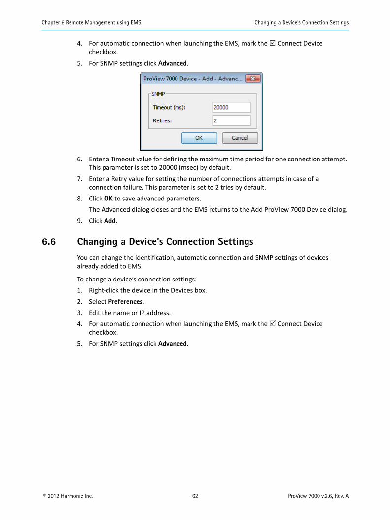
Chapter 6 Remote Management using EMS Changing a Device’s Connection Settings
© 2012 Harmonic Inc. 62 ProView 7000 v.2.6, Rev. A
4. For automatic connection when launching the EMS, mark the Connect Device checkbox.
5. For SNMP settings click Advanced.
6. Enter a Timeout value for defining the maximum time period for one connection attempt. This parameter is set to 20000 (msec) by default.
7. Enter a Retry value for setting the number of connections attempts in case of a connection failure. This parameter is set to 2 tries by default.
8. Click OK to save advanced parameters.The Advanced dialog closes and the EMS returns to the Add ProView 7000 Device dialog.
9. Click Add.
6.6 Changing a Device’s Connection SettingsYou can change the identification, automatic connection and SNMP settings of devices already added to EMS.
To change a device’s connection settings:1. Right-click the device in the Devices box.2. Select Preferences.3. Edit the name or IP address.4. For automatic connection when launching the EMS, mark the Connect Device
checkbox.5. For SNMP settings click Advanced.

Chapter 6 Remote Management using EMS Connecting a Device
© 2012 Harmonic Inc. 63 ProView 7000 v.2.6, Rev. A
6.7 Connecting a DeviceConnect a ProView 7000 device to enable the EMS to monitor and control the device. A disconnected ProView 7000 device is marked in the device list by a grayed device icon.
To connect a ProView 7000 device to the EMS:1. Right-click the ProView 7000 device icon in the Devices box.
A device context menu displays.
2. Select Connect.If the device fails to connect, the device LEDs in the Devices box are red, perform the procedure in 6.8 Checking Device Connectivity.
If the ping fails and the device fails to connect, check your network connections and settings.
Once connection is established, the device icon LEDs are green.

Chapter 6 Remote Management using EMS Checking Device Connectivity
© 2012 Harmonic Inc. 64 ProView 7000 v.2.6, Rev. A
6.8 Checking Device ConnectivityYou can ping any ProView 7000 device managed by the EMS disregarding its status.
To test the device connectivity:1. Right-click the icon of the ProView 7000 device in the Devices box.
A Device context menu displays.
2. Select Ping… in the menu.The Ping test dialog displays with the IP address of the device.
3. Click Ping.A message displays the response of the device to the test.
4. Click OK to confirm the test result.5. Click Close to complete the ping test.

Chapter 6 Remote Management using EMS Disconnecting a Device
© 2012 Harmonic Inc. 65 ProView 7000 v.2.6, Rev. A
6.9 Disconnecting a DeviceA connected ProView 7000 device is communicating with the ProView 7000 EMS and is marked in the device list by a fully colored device icon. The icon is displayed in the Device box, and, if activated, it is also displayed in the Physical Input and Physical Output boxes.
Disconnecting a device closes the tab and all relevant information displayed on the Device Explorer tab for the device.
To disconnect a connected ProView 7000 device from the EMS:1. Right-click the icon of the connected ProView 7000 device in the Device box.
A device context menu displays.
2. Select Disconnect in the menu.The ProView 7000 device disconnects.The colors of the ProView 7000 device icon fade to the disconnected shades (gray).

Chapter 6 Remote Management using EMS Removing a Device
© 2012 Harmonic Inc. 66 ProView 7000 v.2.6, Rev. A
6.10 Removing a DeviceRemoving, or Deleting a ProView 7000 device from the EMS management, disconnects all communication between the device and EMS and the device is no longer available via EMS. To regain access to the device using EMS, add the device to EMS, see 6.5 Adding a Device for details.
Removing a device from the EMS management can be performed on any ProView 7000 device (i.e., listed in the Device box), regardless of its status; connected (full color icon), disconnected (gray icon) or even a not responding device (red marked icon).
To remove a device:1. Select the device which needs to be removed.
2. Click Remove on the EMS toolbar—or—select Action > Remove—or—press <Delete>.A confirmation dialog displays.
3. Select OK.The device is removed from the device list.
6.11 Displaying the Device ExplorerPrerequisites:
Device must be added to the Devices box Device must be connected
To display the Device Explorer1. Select the device in the Devices box of the EMS window.2. Click Device Explorer in the EMS toolbar to display input and output stream trees.
6.12 EMS GUI StructureThe ProView 7000 Element Management System (EMS) is an intuitive graphical user interface (GUI) which enables you to manage ProView 7000s over a LAN. The main EMS components are:
Pull-down menus Toolbar The Devices box The Device Explorer tabs The Alarms tab The Alarm History tab
See Figure 6–2 for EMS component names.

Chapter 6 Remote Management using EMS Manipulating EMS GUI Components
© 2012 Harmonic Inc. 67 ProView 7000 v.2.6, Rev. A
6.13 Manipulating EMS GUI ComponentsThe EMS GUI displays the graphical information in boxes. These boxes can be collapsed when not needed or expanded to fill all available screen space.
Use the triangles to expand or collapse boxes, see Figure 6–2. Click and drag box borders to resize boxes, see Figure 6–2.
6.14 Refreshing the EMS ScreenThe EMS supports a user-driven screen refresh function. This function can refresh the following: Element – Updates a branch or specific element in the stream, either at the multiplexed
input or the multiplexed output. Device – Updates the currently managed ProView 7000 device.
To refresh an element or device:1. Select an element or device.2. Select File > Refresh > [device|element]
—or—click Refresh on the EMS Toolbar.
You can also perform a refresh by right-clicking the element icon and selecting the Refresh item in the displayed element drop-down menu.

Chapter 6 Remote Management using EMS Refreshing the EMS Screen
© 2012 Harmonic Inc. 68 ProView 7000 v.2.6, Rev. A
Figure 6–2: ProView 7000 EMS Graphical User Interface
EMS MenuEMS Toolbar
Device stream tab
Device box
Physical Input port box Multiplex Input box Multiplex and decoding Output box
Physical Output port box
Alarm history tab
Box expand/collapse control
Alarm report tab
Status bar
Box border

Chapter 6 Remote Management using EMS Refreshing the EMS Screen
© 2012 Harmonic Inc. 69 ProView 7000 v.2.6, Rev. A
6.14.1 EMS Device Explorer
The Device Explorer tabs display the input and output stream parameters for the selected device. The tab is divided into four management boxes, namely:
The Physical Input box The Multiplex Input box The Multiplex & Decoding Output box The Physical Output box
Use these parameters to monitor and configure the device.
You can manage several devices with the EMS. Each device stream tab is labeled with the same device name that displays in the Devices box. The selected device stream tab label displays in white. All other tab labels display in gray.
To display the Device Explorer tab: Select File > Open Device Explorer and select a device from the displayed device list.
—or—1. Right-click the icon of the ProView 7000 device in the Device Management box.
The Device context menu displays.
2. Select Open Device Explorer for ProView 7000 Name in the menu.The Device Explorer tab for the selected device displays.
To bring device stream tab to the top: Click a tab label
—or— Double-click the icon of the device in the Devices box.

Chapter 6 Remote Management using EMS Refreshing the EMS Screen
© 2012 Harmonic Inc. 70 ProView 7000 v.2.6, Rev. A
The Device Explorer tab displays a hierarchy-map of the input and output ports, transport-streams, programs, elementary streams, PIDs, Tables, CAMs and decoders that are currently connected and cross-connected by the ProView 7000 selected for management on the EMS.
Figure 6–3: Device Explorer tab
The Device Explorer tab is divided into four boxes, see Figure 6–3. It comprises: Physical Input ports box, deals with the features of the device input physical interfaces
(see 7.1 Physical Input Ports and Slots). Multiplex Input box, deals with the multiplexing features of the input stream (see
7.2 Multiplex Inputs). Multiplex & Decoding Output box, deals with the multiplexing and decoding features of
the output stream (see 7.3 Multiplex & Decoding Outputs). Physical Output ports box, dealing with the features of the device output physical
interfaces (see 7.4 Physical Outputs).
The ProView 7000 EMS GUI uses a wide range of icons to identify elements displayed on the Device Explorer tab, see Appendix C, Device Explorer Icons.
Physical Input Multiplex Input Physical OutputMultiplex & Decoding Output
Device Explorer tab

© 2012 Harmonic Inc. 71 ProView 7000 v.2.6, Rev. A
Chapter 7Device Configuring Using EMS
Topics:
Physical Input Ports and Slots
Multiplex Inputs
Multiplex & Decoding Outputs
Physical Outputs
Element Properties
Cross Connections
CAM Slot Management
EMS Connection Wizard Low Delay Mode Device Management Device Properties
7.1 Physical Input Ports and SlotsThe Physical Input box on the Device Explorer tab presents a hierarchical tree-structure of the ProView 7000 physical inputs, see Figure 6–2 for the box location.
Use the Device Explorer tabs to manage streams, physical ports, multiplexes and CAMM slots.
The ProView 7000 has the following inputs:
ASI input ports.
DVB-S/S21 RF modulated inputs.2
When the DVB-S/S2’s carrier and demodulator are locked, the icon LEDs are green, when they are not locked the icon LEDs are red. See Figure 7–34.
GbE ports3. CAM slots, responsible for the descrambling process.
To display the context menu: Right-click an element.
1. Requires a license with some hardware configurations, see Appendix C for details.2. Not all hardware configurations support 4 demodulator ports, see Appendix C on page 166.3. GbE in requires a license.

Chapter 7 Device Configuring Using EMS Physical Input Ports and Slots
© 2012 Harmonic Inc. 72 ProView 7000 v.2.6, Rev. A
Related Topics:
ASI Input Port Properties DVB-S/S2 Input Port Properties GbE Ports for Input CAM Slots CAM Properties BISS Table Management
7.1.1 ASI Input Port Properties
The ASI Input Port Properties dialog displays the basic features of the selected ASI Input Port element.
To display the ASI Input Port properties:1. Select the required ASI Input Port icon in the Input Physical box in the Stream Managing
tab.2. Click Properties on the EMS toolbar.
The displayed properties are informative only and consist of the description of the ASI Input Port and the description of the Input Multiplex Port.
7.1.2 DVB-S/S2 Input Port Properties
The DVB-S/S2 Input Port properties dialog displays the basic features of the selected DVB-S/S2 Input Port element.
To display the DVB-S/S2 Input Port properties:1. Select the DVB-S/S2 Input Port icon in the Physical Input box.2. Click Properties on the EMS toolbar.

Chapter 7 Device Configuring Using EMS Physical Input Ports and Slots
© 2012 Harmonic Inc. 73 ProView 7000 v.2.6, Rev. A
Figure 7–1: DVB-S/S2 Input Port Properties
The editable properties comprise of the following:
Modulation Standard – Options:
Automatic1
DVB-S
DVB-S21
NOTE: Some of the following properties are relevant for only one modulation standard (DVB-S or DVB-S2) and displayed accordingly.
Symbol Rate – Sets the symbol rate value. Range 1,000,000 – 45,000,000 Bd, adjustable in 100 Bd steps.
Spectral Inversion – Sets the mode of operation for the spectral inversion function. Options:
Automatic – Default for DVB-S.1
Normal – Default for DVB-S2.1
Inverted
1. Only available with certain hardware configurations, see Appendix C on page 166.

Chapter 7 Device Configuring Using EMS Physical Input Ports and Slots
© 2012 Harmonic Inc. 74 ProView 7000 v.2.6, Rev. A
Modulation and FEC – Sets the modulation scheme and forward error correction for the receiver. DVB-S options:
• Automatic – modulation and FEC set by the device• QPSK 1/2• QPSK 2/3• QPSK 3/4• QPSK 5/6• QPSK 7/8
DVB-S2 options:
• VCM1 – Variable Coding Modulation format / Automatic1
• QPSK 1/41
• QPSK 1/31
• QPSK 2/51
• QPSK 1/2• QPSK 3/5• QPSK 2/3• QPSK 3/4• QPSK 4/5• QPSK 5/6• QPSK 8/9• QPSK 9/10• 8PSK 3/5• 8PSK 2/3• 8PSK 3/4• 8PSK 5/6• 8PSK 8/9• 8PSK 9/10
• 16APSK 2/31
• 16APSK 3/41
• 16APSK 4/51
• 16APSK 5/61
• 16APSK 8/91
• 16APSK 9/101
1. A license is required for 16APSK modulation. Only available with certain hardware configurations, see Appendix C on page 166.

Chapter 7 Device Configuring Using EMS Physical Input Ports and Slots
© 2012 Harmonic Inc. 75 ProView 7000 v.2.6, Rev. A
Frame Size1 – DVB-S2 only. Options: Normal frame (64,800 bits) Short frame (16,200 bits)
Pilot Symbols – DVB-S2 only. Options:
Automatic1
On – the demodulator expects to find pilot symbols in the stream. Off – the demodulator does not expect not to find pilot symbols.
NOTE: Not finding pilot symbols when expected, or finding them when not expected, prevents demodulator lock.
Physical Layer Scrambling Seed – Enables the user to set the value for the scrambling seed. DVB-S2 only. Range: 0 – 262,141.
Roll-Off Factor – DVB-S2 only. Options:
Automatic1
20% 25% 35%
Acquisition Mode2 – Sets the frequency scanning span of the receiver when searching for the satellite carrier frequency (lock acquisition search range). Options: Narrow Wide
NOTE: Wide search is the normal operation mode of the receiver frequency acquisition scan. Narrow Search mode should be used when symbol rate of the input is lower than 5 MBd.
Frequency Drift Compensation – Compensate for LNB frequency drift, see Appendix C, Front End Card Features for board details. Options: On Off
BER Threshold (DVB-S only) – Sets the threshold limit to raise the Bit Error Rate alarm. Range: 0.00001 (0.1x10⁻⁴) – 0.1.
PER Threshold (DVB-S2 only) – Sets the threshold limit to raise Packet Error Rate alarm. Range: 0.00000001 (0.1x10⁻⁷) – 0.1.
Attenuation Level2 – Internal attenuation for saturated signals (0 – 30 dB).
Gain2 – Internal gain to improve signal strength. ISI (Hex) (0-FF) – Input Stream Identifier in hexadecimal. Use this parameter to select a
specific transport stream from a multi-transport carrier. If you have a quad port demodulator card then you can select up to 4 transport streams from 4 single or a multi-transport stream carrier.
1. Only available with certain hardware configurations, see Appendix C on page 166.2. Only available with certain hardware configurations, see Appendix C on page 166.

Chapter 7 Device Configuring Using EMS Physical Input Ports and Slots
© 2012 Harmonic Inc. 76 ProView 7000 v.2.6, Rev. A
Carrier Frequency properties – Radio buttons selection, therefore only one is selected at a time. Changing the value on one option, changes the other one automatically: L-Band Frequency Range – Sets the L-Band frequency of the receiver local oscillator.
Range: 950,000 – 2,150,000 (in kHz), adjustable in 125 kHz steps. Frequency for the band selected in LNB – Sets the frequency of the satellite, according
to the satellite transmitting frequency, adjustable in .125 kHz steps.
LNB (Low Noise Block) Properties: Polarization – Antenna polarization. Options:
• 13V (Vertical)• 18V (Horizontal)• Off
LNB Frequency Band – The default is Universal. Options:• Universal (9.75, 10.6)• Universal Wide (9.75, 10.75)• Ku• C
LNB Local Oscillator Frequency (kHz) – For Universal and Universal Wide satellite frequencies, the LNB Local Oscillator Frequency is set according to the 22 kHz Tone setting. For Ku band, adjustable, in the 8.5 GHz – 13 GHz range, in 125 kHz steps. For C band, adjustable, in the 5 GHz – 6 GHz range, in 125 kHz steps.
22 kHz Tone – Low Band or High Band selectable for Universal and Universal Wide satellite frequencies (not applicable for Ku band and C band frequencies and not displayed when Ku or C band are selected)

Chapter 7 Device Configuring Using EMS Physical Input Ports and Slots
© 2012 Harmonic Inc. 77 ProView 7000 v.2.6, Rev. A
7.1.3 GbE Ports for Input
The GbE branch comprises four sockets and two GbE ports. All sockets are associated to both GbE ports by default.
Related topics: GbE Port Properties GbE Socket Properties GbE PHY Redundancy
7.1.3.1 GbE Port Properties
Use the GbE Port Properties dialog to view and configure the selected GbE port.
NOTE: Changing GbE port properties reflects in the Physical Input and Physical Output boxes.
To display the GbE Port properties:1. Select the required GbE Port icon in the Physical Input box on the Device Explorer tab.2. Click Properties on the EMS toolbar.
The GbE Port Properties dialog displays.
The GbE Port Properties dialog comprises of a General and an Advanced tab.
GbE Port General properties tab:
Enabled – You can enable either or both GbE ports. This parameter only works when the redundancy mode is manual, see 7.1.3.3 GbE PHY Redundancy. If both ports are enabled then only one port is active while the other one is in standby mode, by default Port 1 is active and Port 2 is on stand by. The port on stand by does not pass data. When the port is enabled and no link is detected, the device reports a link down alarm. Disable the port to mask this alarm. The default is Disabled.
Redundancy Mode – Set one port as the active one and set the others to standby. This parameter only works when the rendundancy mode is manual, see 7.1.3.3 GbE PHY Redundancy.

Chapter 7 Device Configuring Using EMS Physical Input Ports and Slots
© 2012 Harmonic Inc. 78 ProView 7000 v.2.6, Rev. A
IP Profile – Enables you to configure the following: IP Address – Each port must have a different IP Address. The default is 127.127.0.X,
where X is the port number. Mask – The IP mask. The default is 255.255.255.0. MAC Address – Each port has its own MAC Address. They are factory set and cannot be
changed.
Figure 7–2: GbE Port Properties dialog - General tab
GbE Port Advanced properties tab:
Autonegotiation Enabled – You can enable and disable Autonegotiation. The default is Yes. Duplex Mode – You cannot change the Duplex Mode. It is fixed at Full Duplex. Speed – You can configure the PHY speed when Autonegotiation is disabled. The default is
1000.
Figure 7–3: GbE Port Properties dialog - Advanced tab

Chapter 7 Device Configuring Using EMS Physical Input Ports and Slots
© 2012 Harmonic Inc. 79 ProView 7000 v.2.6, Rev. A
7.1.3.2 GbE Socket Properties
Use the GbE Socket Properties dialog to view and configure the selected GbE port. By default all sockets are associated with both GbE ports.
To display the GbE Socket properties:1. Select the required GbE Socket icon in the Physical Input box on the Device Explorer tab.2. Click Properties on the EMS toolbar.
The GbE Socket Properties dialog displays.
The GbE Socket Properties dialog comprises of a General and an Advanced tab.
GbE Socket General properties tab:
Enabled – You can enable or disable each socket. General parameters box:
Unicast / Multicast – You can select either Unicast or Multicast. Destination IP Address – You can configure the same Destination IP Address and UDP
Port for several sockets if you define the Source Specific Multicast and the Source IP Addresses are different. When the IP Address Type is Unicast, the ProView 7000 uses the active port IP address. When the IP Address Type is Multicast, you must enter the multicast IP address. The default is 238.1.1.X (X is the socket number).
UDP Port – You can configure the same IP Address and UDP Port for several sockets if you define the Source Specific Multicast and the Source IP Addresses are different. The source UDP range is 0 – 65535. The default is 1024.
Source Specific Multicast (SSM) – You can configure Source Specific Multicast when using Multicast addresses to accept only data packets with a matching source address. When SSM is disabled, the device accepts all packets with destination IPs and ports that match the socket regardless of their source IP.
Source IP Address – Enable Source Specific Multicast to enter an SSM source IP address. Connectivity box – Displays the multiplex ins and physical GbE ports associated with the
socket. Status box

Chapter 7 Device Configuring Using EMS Physical Input Ports and Slots
© 2012 Harmonic Inc. 80 ProView 7000 v.2.6, Rev. A
Figure 7–4: Socket Properties dialog - General tab
GbE Socket Advanced properties tab:
Encapsulation Mode – Displays the current encapsulation state. De-Jitter Mode – All input sockets are de-jittered. The options are:
No De-Jitter Low Delay Mode Normal Network Jitter (Less than 50 ms) High Network Jitter (Up to 300 ms) SFN De-Jitter
Figure 7–5: Socket Properties dialog - Advanced tab

Chapter 7 Device Configuring Using EMS Physical Input Ports and Slots
© 2012 Harmonic Inc. 81 ProView 7000 v.2.6, Rev. A
7.1.3.3 GbE PHY Redundancy
GbE Port 1 is always the primary port. GbE Port 2 is always the backup port. The primary port (GbE Port 1) is the active port and the backup port is the standby port by default.
There are 4 modes:
Manual – you can manually switch between the primary port and the backup port regardless of their link status.
Manual Revert – the device switches from the primary port to the backup port when the primary port fails on one of the redundancy triggers and the backup port has no active alarms. You can revert from the backup port to the primary port manually.
Automatic – the device switches to the standby port whenever the active port fails on one of the redundancy triggers and the standby port has no active alarms.
Automatic Revert – the device switches from the primary port to the backup port when the primary port fails on one of the redundancy triggers and the backup port has no active alarms. The device reverts to the primary as soon as the primary port has no active alarms.
To set the GbE redundancy mode:1. Right-click a GbE port in the Physical Input box.2. Select Redundancy Configuration.3. Select a mode
—or—1. Select Tools > Redundancy Configuration.2. Select a mode.
To set a port as the active port:1. Right-click the port in the Physical Input box.2. Select Set Active
—or—use the port properties dialog, see 7.1.3.1 GbE Port Properties.

Chapter 7 Device Configuring Using EMS Physical Input Ports and Slots
© 2012 Harmonic Inc. 82 ProView 7000 v.2.6, Rev. A
7.1.4 CAM Slots
The ProView 7000 has two PCMCIA slots and the ProView 7100 has four PCMCIA slots on the front panel that can each accommodate a DVB-CI module with a smart card to descramble incoming video, see Figure 3–1 on page 32 for the location.
7.1.4.1 Inserting a CAM
1. Insert the smart card into a DVB-CI module with the contacts facing up and towards the front end.
2. Insert the DVB-CI module into one of the two PCMCIA slots with the up arrow pointing upwards and in the direction of insertion.
CAUTION: Do not remove or insert the DVB-CI module or the smart card while the ProView 7000 is powering up or initializing.
Figure 7–6: ProView 7000 with the DVB-CI module and Smart Card
When installed, the card is detected automatically by the ProView 7000 and enabled if the following conditions are met: The installed card must be EN50221 compatible Services have been selected A valid card license
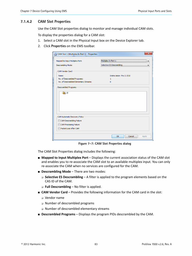
Chapter 7 Device Configuring Using EMS Physical Input Ports and Slots
© 2012 Harmonic Inc. 83 ProView 7000 v.2.6, Rev. A
7.1.4.2 CAM Slot Properties
Use the CAM Slot properties dialog to monitor and manage individual CAM slots.
To display the properties dialog for a CAM slot:1. Select a CAM slot in the Physical Input box on the Device Explorer tab.2. Click Properties on the EMS toolbar.
Figure 7–7: CAM Slot Properties dialog
The CAM Slot Properties dialog includes the following:
Mapped to Input Multiplex Port – Displays the current association status of the CAM slot and enables you to re-associate the CAM slot to an available multiplex input. You can only re-associate the CAM when no services are configured for the CAM.
Descrambling Mode – There are two modes: Selective ES Descrambling – A filter is applied to the program elements based on the
CAS ID of the CAM. Full Descrambling – No filter is applied.
CAM Vendor Card – Provides the following information for the CAM card in the slot: Vendor name Number of descrambled programs Number of descrambled elementary streams
Descrambled Programs – Displays the program PIDs descrambled by the CAM.

Chapter 7 Device Configuring Using EMS Physical Input Ports and Slots
© 2012 Harmonic Inc. 84 ProView 7000 v.2.6, Rev. A
CAM Automatic Recovery Policy – You can configure the ProView 7000 to reset the CAM when one of the following alarms is raised: CAM Descrambling Failure – Enabled by default. CAM Processing Failure – Enabled by default. Packet Loss after CAM – Disabled by default.
7.1.5 CAM Properties
The CAM Card Properties dialog displays the properties of the selected CAM element.
To display the CAM properties:1. Select the required CAM icon in the Input Physical box on the Device Explorer tab.2. Click Properties on the EMS toolbar.
Figure 7–8: CAM Card properties dialog
The information displayed by the CAM Card Properties dialog includes the following:
CAM application type CAM manufacturer name, number and code Conditional Access System IDs CAM operational status Number of descrambled programs and elementary streams

Chapter 7 Device Configuring Using EMS Physical Input Ports and Slots
© 2012 Harmonic Inc. 85 ProView 7000 v.2.6, Rev. A
To display the CAM MMI menu: Click CAM MMI….
The CAM MMI dialog displays.
Figure 7–9: Sample CAM MMI dialog
Different CAMs have different options.
7.1.6 BISS Table Management
By default the Multiplex In 1 passes through the BISS descrambler, you cannot associate other multiplex ins but you can bypass the BISS descrambler.
Related topics:
To Bypass the BISS Descrambler BISS Table Management dialog To Configure a BISS Key To Clear a BISS Key
To Bypass the BISS Descrambler
Bypassing the BISS descrambler:1. Right-click the BISS icon in the Physical Input box.2. Select Disable BISS.
BISS Table Management dialog
Use the BISS Table Management dialog to configure or remove keys.
Displaying the BISS Table Management dialog:1. Expand the device tree in the Physical Input box to display the Descrambling branch with
the BISS node.2. Right-click BISS.3. Select Properties.

Chapter 7 Device Configuring Using EMS Multiplex Inputs
© 2012 Harmonic Inc. 86 ProView 7000 v.2.6, Rev. A
To Configure a BISS Key
Configuring a key:1. Select a key.2. Click Edit.3. Enter the new values.4. Click OK.
To Clear a BISS Key
You cannot clear a key that is in use.
Clearing a key:1. Select a key.2. Click Clear.
7.2 Multiplex InputsThe Multiplex Input box of the Device Explorer tab presents a hierarchical tree-structure of the multiplex inputs of the ProView 7000, see Figure 6–2 for the box location.
It provides monitoring and configuring options for the features of each element in the tree:
Input programs and elementary streams related to the multiplex input. Input tables related to the multiplex input. Unreferenced PIDs related to the multiplex input.
NOTE: The Multiplex Input tree displays the transport rate level (in Mbps), summed at the tree highest level.
The ProView 7000 supports up to four multiplex inputs.1
To display the context menu: Right-click the Multiplex Input icon.
1. A license is required for more than one multiplex input.

Chapter 7 Device Configuring Using EMS Multiplex Inputs
© 2012 Harmonic Inc. 87 ProView 7000 v.2.6, Rev. A
Related topics:
Input Programs Management Input Tables Management Input Unreferenced PIDs Management Multiplex Input Properties Input Program Properties Input Elementary Stream Properties Input Conditional Access Messages Properties Input Tables Properties Input Unreferenced PID Properties
7.2.1 Input Programs Management
Click the Programs branch in the Multiplex Input box to display all the programs related to the multiplex inputs and the type of information provided by the program.
Each program can be scrambled or clear (marked accordingly by a locked / free program icon).
The information provided by each program can be video, audio, ECM or other (marked by representative icons).
NOTE: The properties of the input programs and the elementary streams related to each program in the multiplex input stream are detailed in 7.2.5 Input Program Properties, 7.2.6 Input Elementary Stream Properties and 7.3.1.5 Multiplex Output Unreferenced PIDs Management.

Chapter 7 Device Configuring Using EMS Multiplex Inputs
© 2012 Harmonic Inc. 88 ProView 7000 v.2.6, Rev. A
7.2.2 Input Tables Management
Click the Tables branch in the Multiplex Input box to display all the tables related to the multiplex input and the type of information provided by the table.
The Input Tables branch provides access to the following MPEG PSI and DVB PSI/SI tables related to the multiplexed stream:
Program Association Table (PAT) for the stream Conditional Access Table (CAT) and the specific Entitlement Management Messages (EMM)
in the CAT Program Map Tables (PMTs) for each multiplex program Network Information Table (NIT) Service Description Tables (SDTs) Event Information Table (EIT) Time and Date Table (TDT/TOT) associated with the stream
NOTE: The displayed tables are managed by the stream type defined (MPEG or DVB). The property of the various input tables in the multiplexed input stream is detailed in 7.2.8 Input Tables Properties.

Chapter 7 Device Configuring Using EMS Multiplex Inputs
© 2012 Harmonic Inc. 89 ProView 7000 v.2.6, Rev. A
7.2.3 Input Unreferenced PIDs Management
Click the Unreferenced PIDs branch in the Multiplex Input box to display all the PIDs related to the multiplex input that are not referred to a specific program or table.
NOTE: The properties of the input unreferenced PIDs in the multiplexed input stream is detailed in 7.2.9 Input Unreferenced PID Properties.
7.2.4 Multiplex Input Properties
The Multiplex Input Properties dialog displays the current status of input features and enables setting up the editable ones.
To display the Multiplex Input dialog:1. Select the Multiplex Input icon in the Multiplex Input box on the Device Explorer tab.2. Click Properties on the EMS toolbar.
The information provided by the Multiplex Input Properties dialog includes the following:
Enabled – Enables (Yes/No) the multiplex input operation. Transport Stream ID – Displays the transport-stream’s ID number. Table Extraction – Select PSI/SI for DVB or PSI for MPEG. The default is PSI/SI.

Chapter 7 Device Configuring Using EMS Multiplex Inputs
© 2012 Harmonic Inc. 90 ProView 7000 v.2.6, Rev. A
NOTE: For ATSC systems, set the stream type to MPEG.
Assigned CAMs – Displays any CAM slots assigned to the multiplex input. Connected Input Physical Port – Selects the physical input port for the multiplex input.
7.2.5 Input Program Properties
The Input Program properties dialog provides basic information on the input program provided to the input multiplex over the received transport stream.
To display the Input Program properties dialog:1. Select the required Input Program icon in the Multiplex Input box on the Device Explorer
tab.2. Click Properties on the EMS toolbar.
The information displayed by the Input Program Properties dialog includes the following:
The Program Clock Reference identification number (PCR PID).
The Program Map Table identification number (PMT PID).
The program reference number.

Chapter 7 Device Configuring Using EMS Multiplex Inputs
© 2012 Harmonic Inc. 91 ProView 7000 v.2.6, Rev. A
7.2.6 Input Elementary Stream Properties
The Input Elementary Stream (ES) properties dialog provides basic information on the stream included in the input program provided to the input multiplex. The ES input multiplex tree displays Video, Audio and Other (such as DVB Subtitling) types of streams for each program.
To display the Input ES properties:
1. Select the required ES icon (Video , Audio or Other ) in the Multiplex Input box on the Device Explorer tab.
2. Click Properties on the EMS toolbar.
The information displayed by the Input ES Properties dialog includes the following:
The program identification number (PID) of the input elementary stream type. The ES type code (in hex) and description. The language code for the ES (Not applicable for Video ES).
7.2.7 Input Conditional Access Messages Properties
The Input Conditional Access Entitlement Control Message (ECM) properties dialog provides basic information on the ECM information included in the input program provided to the input multiplex.
To display the Input ECM properties:
1. Select the required ECM icon in the Multiplex Input box on the Device Explorer tab.2. Click Properties on the EMS toolbar.
The information displayed by the Input ECM Properties dialog includes the following: ECM PID – Displays the entitlement control message identification number of the
conditional access system. CA System ID – Displays the identification of the conditional access system.

Chapter 7 Device Configuring Using EMS Multiplex Inputs
© 2012 Harmonic Inc. 92 ProView 7000 v.2.6, Rev. A
7.2.8 Input Tables Properties
The Input Tables properties dialog provides basic information on the input tables provided to the input multiplex over the received transport stream.
These tables include:
Conditional Access Table (CAT) Program Association Table (PAT) Program Mapping Table (PMT) Service Description Table (SDT) Network Information Table (NIT) Event Information Table (EIT) Time & Date Table (TDT/TOT)
To display the Input Tables properties dialog:1. Select the required Input Table icon from the Multiplex Input box on the Device Explorer
tab.2. Click Properties on the EMS toolbar.
The information provided for each of the Input Table Properties dialog includes the version and number of sections in the table.
The Conditional Access Table (CAT) consists of one (or more) Entitlement Management Message (EMM) for each of the input encrypted streams. Selecting the specific EMM and clicking the [Properties] button displays the EMM properties dialog consisting of the EMM PID and the CA System ID.
The Program Association Table (PAT) properties dialog displays the transport stream ID information, the version and number of the PAT sections.
The Program Mapping Table (PMT) consists of a group of individual tables. Selecting the specific table and clicking the [Properties] button displays the version and number of sections for the selected PMT.
The Service Description Table (SDT) consists of one (or more) services provided on the stream. Selecting the SDT icon and clicking the Properties button displays the common properties of the table, consisting of the version, number of sections data displayed and the identification number of the original network.
Selecting a specific entry in the SDT table (marked as sub-branches of the SDT table brunch) and clicking the Properties button displays the following information for the service: Service ID, Service running status, Service CA mode (free/scrambled), Service name, Service provider name and service type.

Chapter 7 Device Configuring Using EMS Multiplex & Decoding Outputs
© 2012 Harmonic Inc. 93 ProView 7000 v.2.6, Rev. A
7.2.9 Input Unreferenced PID Properties
The Input Unreferenced PID properties dialog provides basic information on an unreferenced stream provided to the input multiplex.
To display the Input Unreferenced PID properties:1. Select the required Unreferenced PID icon from the Multiplex Input box on the Device
Explorer tab.2. Click Properties on the EMS toolbar.
The information provided by the Input Unreferenced PID Properties dialog includes the following:
The packet identification number (PID) of the related input stream. The type of the PID (Unreferenced).
7.3 Multiplex & Decoding OutputsThe Multiplex & Decoding Output box of the Device Explorer tab presents a hierarchical tree-structure of the decoded and multiplex outputs of the ProView 7000, see Figure 6–2 for the box location. It comprises two branch types; multiplexing branches ( ) and the decoding branch ( ).
The multiplexing branch provides monitoring and configuring options for the features of stream and each element in the branch; Programs, Tables and unreferenced PIDs related to the multiplex output. For details, refer to 7.3.1.3 Multiplex Output Programs Management (programs), 7.3.1.4 Multiplex Output Tables Management (tables), 7.3.1.5 Multiplex Output Unreferenced PIDs Management (PIDs).
The decoding branch provides monitoring and configuring options for the features of each element in the branch. For details, see 7.6 Cross Connections.
Transport streams can be routed as they are to the output ports (pass-through). For details, see 7.3.1.7 Pass Through TS Routing.
The ProView 7000 supports up to four multiplex outputs.1
TIP: Creation of multiplex and decoded output streams is detailed in 7.6 Cross Connections.
1. A license is required for more than one multiplex output.

Chapter 7 Device Configuring Using EMS Multiplex & Decoding Outputs
© 2012 Harmonic Inc. 94 ProView 7000 v.2.6, Rev. A
Related topics:
7.3.1 Multiplex Output 7.3.2 Multiplex Output Properties 7.3.3 Transport Stream Port Route Properties dialog 7.3.4 Output Multiplex Program Properties 7.3.5 Output Multiplex Elementary Stream Properties 7.3.6 Output Tables Properties 7.3.7 Output Unreferenced PID Properties 7.3.8 Decoding Channel Properties
7.3.1 Multiplex Output
Right-click a Multiplex Output icon ( ) or any of the sub elements to display a context menu which comprises the following:

Chapter 7 Device Configuring Using EMS Multiplex & Decoding Outputs
© 2012 Harmonic Inc. 95 ProView 7000 v.2.6, Rev. A
7.3.1.1 Multiplexing an Input Program
To multiplex an input program to the output stream:
1. Select the Add Other Program… option in the context menu.The Add Another Program dialog displays.
2. Select the multiplex input port and the program number to multiplex to the output.
Table 7–1: Multiplex Output Context Menu
Disable/ EnableA dynamic command, changing according to the multiplex output operational status.
Add Other Program…Enables adding a program from the multiplex input to the multiplex output programs.NOTE: Not available when the device is configured to pass-through the input stream to the output port.
Add Unreferenced PID…Enables adding a specific PID from the multiplex input to the multiplex output unreferenced PIDs.NOTE: Not available when the device is configured to pass-through the input stream to the output port.
Remove Selected Removes the selected element.
Remove All Removes all output programs or all output unreferenced PID from the multiplex output.
Refresh Port Multiplex Out Updates the Port Multiplex Out.
Properties Displays the marked element properties dialog. For details, see 7.3 Multiplex & Decoding Outputs.

Chapter 7 Device Configuring Using EMS Multiplex & Decoding Outputs
© 2012 Harmonic Inc. 96 ProView 7000 v.2.6, Rev. A
7.3.1.2 Multiplexing an Input PID
To multiplex an input PID (either an unreferenced one or a PID from a defined program) to the output stream:
1. Select the Add Unreferenced PID… option in the context menu.The Add Unreferenced PID dialog displays.
2. Select the multiplex input port and the PID number to multiplex to the output.
TIP: Multiplexing a Program or a PID can be also done by dragging the program icon or the PID icon from the multiplex input tree and dropping it in the multiplex output tree. For detailed instructions 7.6.1 Setting Multiplex Cross Connections.
7.3.1.3 Multiplex Output Programs Management
Click a Program branch in the Multiplex & Decoding Output box to display all the programs related to the multiplex output and the type of information provided by the program.
Each program can be descrambled or clear (marked accordingly by an unlocked / free program icon).
The information provided by each program can be video, audio, ECM or other (marked by representative icons).

Chapter 7 Device Configuring Using EMS Multiplex & Decoding Outputs
© 2012 Harmonic Inc. 97 ProView 7000 v.2.6, Rev. A
NOTE: The properties of the output programs and the elementary streams related to each program in the multiplex output stream are detailed in 7.3.4 Output Multiplex Program Properties and 7.3.5 Output Multiplex Elementary Stream Properties.
7.3.1.4 Multiplex Output Tables Management
Click a Tables branch in the Multiplex & Decoding Output box to display all the tables related to the multiplex output and the type of information provided by the table.
The Output Tables branch provides access to the following MPEG PSI and DVB PSI/SI tables related to the multiplex output stream:
The Program Association Table (PAT) for the stream The Conditional Access Table (CAT) and the specific Entitlement Management Messages
(EMM) included in the CAT The specific Program Map Tables (PMTs) for each multiplex program The Network Information Table (NIT) – passed from the input The specific Service Description Tables (SDTs) The Event Information Table (EIT) – passed from the input The Time and Date Table (TDT/TOT) associated with the stream – passed from the input
NOTE: The displayed tables are managed by the defined stream type (MPEG or DVB). The property of the various output tables in the multiplex output stream is detailed in 7.3.6 Output Tables Properties.

Chapter 7 Device Configuring Using EMS Multiplex & Decoding Outputs
© 2012 Harmonic Inc. 98 ProView 7000 v.2.6, Rev. A
7.3.1.5 Multiplex Output Unreferenced PIDs Management
The Unreferenced PIDs branch in the Multiplex & Decoding Output box displays all the PIDs related to the multiplex output that are not referenced by a specific program or table.
NOTE: The properties of the output unreferenced PIDs in the multiplex output stream is detailed in 7.3.7 Output Unreferenced PID Properties.
7.3.1.6 Decoding Channel Management
Click the Decoding Channel branch in the Multiplex & Decoding Output box to display all the information related to the input program routed to the decoding channel.

Chapter 7 Device Configuring Using EMS Multiplex & Decoding Outputs
© 2012 Harmonic Inc. 99 ProView 7000 v.2.6, Rev. A
The information provided by each program is divided into PCR, Video, Audio 1 and 2, VBI and subtitling information (marked by representative icons).
Right-click a Decoding Channel icon or any of the sub elements in the branch to display a context menu which features the following options:
7.3.1.7 Pass Through TS Routing
Routing a transport stream to an output creates a pass-through output stream, identical to the input TS. In this mode, the stream information is not processed and the output bit rate will be exactly as the input bit rate.
The EMS enables the user to display the programs, tables and unreferenced PIDs available on the transport stream passed-through to the selected output.
Right-click the TS Port Output Port icon or any of the elements in the branch, to display a drop-down menu which features the following items:
Table 7–2: Decoding Channel Context Menu
Command Description
Remove SelectedRemove the selected item, not all items can be removed.
Clear Decoding Channel Connection
Enables removing the decoding channel connection. Clicking the option displays a confirmation dialog.NOTE: Active only from the Decoding Channel up-line branch. Not displayed for a specific down drilled elements.
Refresh Decoding Channel Updates the Decoding Channel.
Properties Displays the marked element properties dialog. For details, see 7.3 Multiplex & Decoding Outputs.

Chapter 7 Device Configuring Using EMS Multiplex & Decoding Outputs
© 2012 Harmonic Inc. 100 ProView 7000 v.2.6, Rev. A
7.3.2 Multiplex Output Properties
The Multiplex Output Port Properties dialog displays the current status of the multiplex output stream features and enables setting up the editable ones.
To display the Multiplex Output Stream Properties dialog:1. Select the Multiplex Output icon from the Multiplex & Decoding Output box on the
Device Explorer tab.2. Click Properties on the EMS toolbar.
Figure 7–10: Multiplex Out 1 Port - Properties dialog
The information provided by the Multiplex Output Properties dialog includes the following: Enabled – Enables (Yes/No) the multiplex output operation. Transport Stream ID – Displays the transport-stream’s ID number. Table Extraction – Select PSI/SI for DVB or PSI for MPEG. The default is PSI/SI. Configured Bitrate – Displays the calculated bitrate of the output stream (in bps). Actual Bitrate – Displays the actual bitrate of the output stream (in bps), not including
NULL stuffing.
Table 7–3: TS Port Output Port Context Menu
Command Description
Disable/ EnableA dynamic command, changing according to the operational status of the TS Output Port.
Remove Selected Removes the selected element.
Remove All Displays the following sub-menu items: Remove All Output Programs on Port Remove All Output Programs on Device Remove All Output Unreferenced PIDs on Port
Refresh Transport Stream Port Route
Updates the Transport Stream Port Route.
Properties Displays the marked element properties dialog. For details, see 7.3 Multiplex & Decoding Outputs.

Chapter 7 Device Configuring Using EMS Multiplex & Decoding Outputs
© 2012 Harmonic Inc. 101 ProView 7000 v.2.6, Rev. A
7.3.3 Transport Stream Port Route Properties dialog
The Transport Stream Port Route Properties dialog displays the current status of a transport stream routed to an output port.
To display the Transport Stream Port Route Properties dialog:1. Select the TS port route icon in the Multiplex & Decoding Output box on the Device
Explorer tab.2. Click Properties on the EMS toolbar.
Figure 7–11: Transport Stream Port Route Properties dialog
The information provided by the Transport Stream Port Route Properties dialog includes the following: Enabled – Enables (Yes/No) the output port operation. Input Port – Displays the multiplex input port name. Transport Stream ID – Displays the transport stream ID number. Output Port – Displays the stream output port name.

Chapter 7 Device Configuring Using EMS Multiplex & Decoding Outputs
© 2012 Harmonic Inc. 102 ProView 7000 v.2.6, Rev. A
Passed Program list – Displays a list of the programs passed in the stream and their descrambling status. Click Add… next to the list to open an Add Other Program dialog which enables the user to define expected programs in the received transport stream (and not available when the TS was routed) and to assign the descrambling CAM to the program.
Figure 7–12: Add Other Program dialog
Descrambling Configuration Not Descrambled CAM Slot 1 CAM Slot 2 CAM Slot 3 CAM Slot 4
Descrambling Status Descrambled Not Descrambled
7.3.4 Output Multiplex Program Properties
The Output Program properties dialog provides basic information on the output program provided by the output multiplex.
To display the Output Multiplex Program properties dialog:1. Select the required Output Program icon from the Multiplex and Decoding Output box on
the Device Explorer tab.2. Click Properties on the EMS toolbar.
Figure 7–13: Program Properties dialog

Chapter 7 Device Configuring Using EMS Multiplex & Decoding Outputs
© 2012 Harmonic Inc. 103 ProView 7000 v.2.6, Rev. A
The Program Properties dialog contains the following items:
Enabled PCR PID PMT PID Program Number Input Port Input Program Descramble With – Check the checkbox to enable the user to select the CAM Slot from
the pull-down list Descrambled Status
7.3.5 Output Multiplex Elementary Stream Properties
The Output Elementary Stream (ES) properties dialog provides basic information on the output stream included in the output program provided to the output multiplex.
To display the Output Multiplex ES properties:
1. Select the required ES icon (Video , Audio or Other ) in the Multiplex and Decoding Output box on the Device Explorer tab.
2. Click Properties on the EMS toolbar.
Figure 7–14: Video Elementary Stream Properties dialog
The information displayed by the Output Multiplex ES Properties dialog includes the following: PID – The program identification number (PID) of the output elementary stream type
Type Description – The ES type Stream Type (hex) – The ES type code Stream Type Description – Encoding and description Language – The language code for the ES (Not applicable for Video ES) Input Program – The number of the input program multiplex to the output program Input Elementary Stream PID – The PID of the input elementary stream multiplex to the
output program

Chapter 7 Device Configuring Using EMS Multiplex & Decoding Outputs
© 2012 Harmonic Inc. 104 ProView 7000 v.2.6, Rev. A
7.3.6 Output Tables Properties
The Multiplex and Decoding Output box on the Device Explorer tab provides managing access to the DVB PSI/SI related tables provided in the multiplex output stream.
These tables include:
Program Association Table (PAT) Program Mapping Table (PMT) Conditional Access Table (CAT) Service Description Table (SDT) Network Information Table (NIT) Event Information Table (EIT) Time and Date Table (TDT/TOT)
To display the Output Tables properties:1. Select the required Output Table icon from the Multiplex and Decoding Output box on
the Device Explorer tab.2. Click Properties on the EMS toolbar.
The information provided for each of the output tables includes the following: Table Passed State – Enables selecting the table source for the multiplex output. Options:
Generated by the Device Passed from the Input Not Passed
Repetition Rate – Enables setting up the table transmission repetition rate (in msec). Transport Stream ID – Displays the identification of the transport stream for the table. Version – Displays the table version. Number of Sections – Displays the number of sections used to construct the table.

Chapter 7 Device Configuring Using EMS Multiplex & Decoding Outputs
© 2012 Harmonic Inc. 105 ProView 7000 v.2.6, Rev. A
7.3.6.1 The PMT
The Program Mapping Table (PMT) consists of a group of programs that can independently be enabled to the multiplex output.
The PMT Properties dialog enables setting the repetition rate for all PMTs and the specific PMT properties dialog enables setting the table source and displays the table version and number of sections.
7.3.6.2 The CAT
The Conditional Access Table (CAT) consists of one (or more) Entitlement Management Message (EMM). Select the CAT icon and click the Properties button to display the common properties for the all EMMs in the CAT.
7.3.6.3 The EMM
Select a specific EMM icon in the CAT and click the Properties button to display the following information for the EMM: output and input PID, input port name and CA system ID.

Chapter 7 Device Configuring Using EMS Multiplex & Decoding Outputs
© 2012 Harmonic Inc. 106 ProView 7000 v.2.6, Rev. A
7.3.6.4 The SDT
The Service Description Table (SDT) consists of a group of services with specific parameters.
Each specific SDT Properties dialog provides the service provider information, the service ID, service type and service name, the service operational status and the service CA operational mode.
7.3.7 Output Unreferenced PID Properties
The Output Unreferenced PID properties dialog provides basic information on an unreferenced stream provided to the multiplex output.
To display the Output Unreferenced PID properties:1. Select the required Unreferenced PID icon in the Output Multiplex & Decoding box on the
Device Explorer tab.2. Click Properties on the EMS toolbar.
The information provided by the Output Unreferenced PID Properties dialog includes the following: Output PID – Displays the PID number of the multiplex output stream. Type – Displays the type of the PID (Unreferenced). Input Port – Displays the name of the input physical port which receives the stream. Input PID – Displays the PID number of the related input stream.

Chapter 7 Device Configuring Using EMS Multiplex & Decoding Outputs
© 2012 Harmonic Inc. 107 ProView 7000 v.2.6, Rev. A
7.3.8 Decoding Channel Properties
To configure the decoding channel properties: Right-click a decoding channel in the Multiplex & Decoding Output box, see Figure 6–2
for the box location.
Related Topics:
Service Parameters Tab Video Parameters Tab PCR Parameters Tab Audio 1/2 Parameters Tab VBI/VANC Tab OSD Parameters Tab
7.3.8.1 Service Parameters Tab
The Service parameters tab provides the EMS user the following information and set-up capabilities:
Source box – displays the stream input source and input program name for the decoder. Service Selection Mode drop-down menu options:
• Automatic – Use this mode for ProView 7000 to automatically decode the first program in the TS (first PMT)
• Program – Use this mode to set the decoder to manual program selection• PID – Use this mode to set the decoder to manual PID selection• No Decoding – Use this mode to disable decoding
PID Selection box – Displays the PID for the program PCR and to select the elementary stream PID for the Video and the VBI/VANC processing. It also enables the user to set the ES PID and preferred language for each one of the two audio streams (Audio1 and Audio2).
Channel Descrambling box• Descramble with – Use this feature to enable stream descrambling and to select a
CAM• Program Status – Shows whether the program is being descrambled and by which
CAM slot.

Chapter 7 Device Configuring Using EMS Multiplex & Decoding Outputs
© 2012 Harmonic Inc. 108 ProView 7000 v.2.6, Rev. A
Figure 7–15: Decoding Channel Properties – Service tab
7.3.8.2 Video Parameters Tab
The Video parameters tab provides the EMS user the following information and set-up capabilities:
General Video processing parameters:
Decoding Codec – selects the video decoding mode.Options: Automatic MPEG-2 H.264
Display Format – selects the video display format. Options: SD HD Automatic

Chapter 7 Device Configuring Using EMS Multiplex & Decoding Outputs
© 2012 Harmonic Inc. 109 ProView 7000 v.2.6, Rev. A
The video output set-up depends on the display format selected:
Standard Definition (SD) Digital and Analog Output parameters:
Video Format – selects the video format. Options: NTSC PAL-B/G, -I, -D, -M, -N French SECAM – The CV monitor output—outputs Russian SECAM as French SECAM.
Aspect Ratio Conversion – selects the aspect ratio conversion for the output stream. To be performed if the incoming stream aspect ratio is not the same as the configured output aspect ratio. Options (related to selected aspect ratio): 4:3 Aspect ratio
• Center-cut• Letterbox• Full Screen• AFD
16:9 Aspect ratio• Pillarbox (Side-bars)• Center-cut• Full Screen• AFD
Aspect ratio – selects the aspect ratio. Options: 4:3 16:9 Pass Through

Chapter 7 Device Configuring Using EMS Multiplex & Decoding Outputs
© 2012 Harmonic Inc. 110 ProView 7000 v.2.6, Rev. A
Figure 7–16: Decoding Channel Properties – Video tab
High Definition (HD) Digital Output parameters:
Video Format – selects the video format. Options: 720p@50, 720p@59, 720p@60, 1080i@50, 1080i@59, 1080i@60.
Aspect ratio Conversion – selects the aspect ratio conversion for the output stream. To be performed if the incoming stream aspect ratio is not the same as the configured output aspect ratio. Options: Pillarbox (Side-bars) Full Screen Letterbox Center-cut
CV Mon Output (SD) – sets the parameters for the SD analog (CV) monitoring output, consisting of SD video format, SD aspect ratio and aspect ratio conversion.
Advanced video processing parameters:
Blanking – selects the response for blanking mode (underflow). Options: Black Last Field Last Frame.
Buffer Management – Options: Normal Low Delay – Select this option to use Low Delay mode. GI Mode
Additional Image Processing

Chapter 7 Device Configuring Using EMS Multiplex & Decoding Outputs
© 2012 Harmonic Inc. 111 ProView 7000 v.2.6, Rev. A
7.3.8.3 PCR Parameters Tab
The PCR parameters tab provides the EMS user the following information and set-up capabilities:
Clock Source – You can select one of the following clock sources: Original PCR Decoder Clock
Genlock1 – Use this menu to sync with the incoming signal. The Genlock menu enables two radio buttons:• Analog – Analog genlocking supports PAL B/G and NTSC. The main output must be
configured to PAL B/G or NTSC. When you use an analog clock source you can configure the following:· Horizontal Delay – The range is 0 – 1728 in 37 ns or 27 MHz ticks. The default is 0.· Vertical Delay – The range is -7 – 6. The default is 0.· SCH Phase Delay – The range is 0° – 360°. The default is 0.
• Digital – Digital genlocking supports PAL B/G, NTSC, 720P (50, 59, 60 Hz) and 1080i (50, 59, 60 Hz). The main output must be configured to PAL B/G, NTSC, 720P (50, 59, 60 Hz) or 1080i (50, 59, 60 Hz).
You must select either Analog or Digital. The default is Digital. A/V Sync – You can select one of the following audio/video synchronization parameters:
Off Frame – Select this parameter to limit the audio/video sync jitter to 1 frame. 5 ms – Select this parameter to limit the audio/video sync jitter to 5ms when the clock
source is set to Original PCR. A/V Offset Compensation – sets the A/V offset compensation. You can only use this
parameter with the 5 ms parameter. The range is -20 – 20 ms. The default is 0. Decoding Buffer Delay – sets the delay time for the buffer. Range: 1 – 300 msec. The
default is 100.
CAUTION: Changing the Decoding Buffer Delay value may cause unpredicted implications in the operation of the device. Consult Harmonic support before changing this parameter.
1. Only available with certain hardware configurations, see Appendix C on page 166.

Chapter 7 Device Configuring Using EMS Multiplex & Decoding Outputs
© 2012 Harmonic Inc. 112 ProView 7000 v.2.6, Rev. A
Figure 7–17: Decoding Channel Properties – PCR tab
7.3.8.4 Audio 1/2 Parameters Tab
The Audio 1/2 parameters tab provides the EMS user the following information and set-up capabilities:
General Audio processing parameters:
Decoding Codec – selects the audio decoding mode. Options: Automatic Musicam Dolby Digital1 (AC-3) Dolby Digital (AC-3) Pass Through
Dolby Digital Plus1 (E-AC-3) – (Audio 1 channel only) AAC LC – (Audio 1 channel only) HE AAC – (Audio 1 channel only)
Dolby E1 / Linear PCM Pass Through – (Audio 2 channel only) Volume – sets the audio volume.
Range: −64 to 0 dB Delay – the delay.
Range: −128 to +128 msec.
1. Dolby, Dolby E, Dolby Digital and Dolby Digital Plus are registered trademarks of Dolby Laboratories.

Chapter 7 Device Configuring Using EMS Multiplex & Decoding Outputs
© 2012 Harmonic Inc. 113 ProView 7000 v.2.6, Rev. A
Analog Mixer – selects the mixing L/R inputs to outputs.Options: Stereo Mono Both Left Both Right
Digital Format – selects the audio format mode.Options: Professional Consumer
Figure 7–18: Decoding Channel Properties – Audio tab
Dolby Digital (AC-3) processing parameters:
Down Mixing Mode – selects the mixing mode for the output. Options: LoRo LtRt
Operational Mode – selects the mode of operation for Dolby Digital processing. Options: Custom 0 Custom 1 Line Out RF Remod

Chapter 7 Device Configuring Using EMS Multiplex & Decoding Outputs
© 2012 Harmonic Inc. 114 ProView 7000 v.2.6, Rev. A
SDI Groups – Audio 1 is always the first pair of channels in a group and Audio 2 is always the second pair of channels in a group:
Group – There are four groups to choose from. The default is group 1. Pair – Cannot be changed.
7.3.8.5 VBI/VANC Tab
The VBI/VANC tab enables you to insert VBI/VANC data into the decoded video. You can insert several VANC datum items into the same line but you cannot insert several VBI items into the same line and you cannot insert VBI and VANC into the same location.
Figure 7–19: Decoding Channel Properties dialog – VBI/VANC tab
The tab provides the following configuration options:
VBI/VANC parameters:
CC (Closed Captions) Source: Video ES
NTSC Parameters:
AMOL (Automatic Measurement Of Line-Ups)Source: VBI ES
TVG (TV Guide)Source: VBI ES
PAL Parameters: WSS (Wide Screen Signalling)
Sources:

Chapter 7 Device Configuring Using EMS Multiplex & Decoding Outputs
© 2012 Harmonic Inc. 115 ProView 7000 v.2.6, Rev. A
Decoder VBI ES Video ES WSS-AFD (when using AFD)
TTX (Teletext EBU)Source: VBI ES
VPS (Video Program System)Source: VBI ES
General Parameters:
VITS (Vertical Interval Test Signals)Source: Decoder
VITC (Vertical Interval Time Code) Sources: Decoder VBI ES Video ES
VI/AFD (Video Index) Sources: VBI ES Video ES
M422 (Monochrome 2:4:4)Source: VBI ES
SCTE-104
SCTE-104 Parameters:
ASI Index DPI PID Index
7.3.8.6 OSD Parameters Tab
The On Screen Display (OSD) enables you to configure the insertion of subtitles. It operates in Auto Mode and Program Mode in HD and SD. The OSD parameters tab provides the EMS user the following information and set-up capabilities:
Subtitling Type: DVB Subtitling
• Decoded PID• PID – Automatic/None• Preferred Language

Chapter 7 Device Configuring Using EMS Physical Outputs
© 2012 Harmonic Inc. 116 ProView 7000 v.2.6, Rev. A
Figure 7–20: Decoding Channel Properties - OSD tab
VBI Teletext – you can search by page or preferred language• Current PID Page• Current PID Preferred Language – first page that contains the specified language
Disabled Subtitles Zoom and Position
You can set the following: Zoom X Posi on – range −100 to 100, the default is 0 Y Posi on – range −100 to 100, the default is 0
7.4 Physical OutputsThe Physical Output box of the Device Explorer tab presents a hierarchical tree-structure of the ProView 7000 physical output ports for monitoring and configuring the features of each element displayed in the tree, see Figure 6–2 for the box location.
The ProView 7000 features various types of outputs: ASI output ports GbE ports and sockets
When the Decoder module is installed in the ProView 7000 device the module provides a wide range of physical video and audio interfaces. All interfaces are displayed under the decoder card branch.

Chapter 7 Device Configuring Using EMS Physical Outputs
© 2012 Harmonic Inc. 117 ProView 7000 v.2.6, Rev. A
Right-click the device icon or any of the sub-elements in the Physical Output box to display a context menu which includes the following items:
Figure 7–21: Physical Output box
Related topics:
ASI Output Port Properties GbE Ports for Output
Table 7–4: Device Icon Context Menu
Command Description
Refresh Updates the physical outputs for the selected device.
Properties Displays the marked element properties dialog for the marked element. For details, see 7.4.1 ASI Output Port Properties, 7.4.2.1 GbE Port Properties, 7.4.2.2 GbE Socket Properties and 7.4.2.3 MPE Properties.NOTE: No properties are available for the decoder output interfaces.

Chapter 7 Device Configuring Using EMS Physical Outputs
© 2012 Harmonic Inc. 118 ProView 7000 v.2.6, Rev. A
7.4.1 ASI Output Port Properties
The ASI Output Port Properties dialog displays the basic features of the selected ASI Output Port element.
To display the ASI Output Port properties:1. Select the required ASI Output Port icon in the Output Physical box on the Device
Explorer tab.2. Click Properties on the EMS toolbar.
The information provided by the ASI Output Port Properties dialog includes the following:
Description – Displays the identification name of the ASI output port. Connected Output Multiplex Port – Enables selecting the multiplex output to connect to
the ASI output port.
7.4.2 GbE Ports for Output
The GbE branch comprises of four sockets, two GbE ports and configurable GbE properties. All sockets are associated to both GbE ports by default.
7.4.2.1 GbE Port Properties
Use the GbE Port Properties dialog to view and configure the selected GbE port. You can enter a virtual IP address for the GbE port for redundancy purposes. The virtual IP address overrides the source IP address on the IP header.
NOTE: Changing GbE port properties reflects in the Physical Input and Physical Output boxes.
To display the GbE port properties:1. Select the required GbE port icon in the Physical Output box on the Device Explorer tab.2. Click Properties on the EMS toolbar.
The GbE Port Properties dialog displays.
The GbE Port Properties dialog comprises of a General and an Advanced tab.
GbE Port General properties tab:
Enabled – You can enable either or both GbE ports. The default is Disabled. IP Profile – Enables you to configure the following:
IP Address – The IP Address must be a multicast IP address. The default is 127.127.0.X, where X is the port number.
Mask – The IP mask. The default is 255.255.255.0.

Chapter 7 Device Configuring Using EMS Physical Outputs
© 2012 Harmonic Inc. 119 ProView 7000 v.2.6, Rev. A
Gateway – The default is 127.127.0.1. MAC Address – Each port has its own MAC Address. They are factory set and cannot be
changed. Override Source IP – Enables the user to send a virtual IP address. Connectivity – Displays the address of the GbE socket related to the port.
Figure 7–22: GbE Port Properties dialog- General tab
GbE Port Advanced properties tab:
Auto negotiation Enabled – You can enable and disable Autonegotiation. The default is Yes.
Duplex Mode – You cannot change the Duplex Mode. It is fixed at Full Duplex. Speed – You can configure the PHY speed when Autonegotiation is disabled. The default is
1000.
Figure 7–23: GbE Port Properties dialog - Advanced tab

Chapter 7 Device Configuring Using EMS Physical Outputs
© 2012 Harmonic Inc. 120 ProView 7000 v.2.6, Rev. A
7.4.2.2 GbE Socket Properties
Use the GbE Socket Properties dialog to view and configure the selected GbE port. By default all sockets are associated with both GbE ports. The data on each socket is sent to both output ports. You cannot associate two sockets with identical destination port and IP addresses to the same GbE port.
To display the GbE Socket properties:1. Select the GbE Socket icon in the Physical Output box on the Device Explorer tab.2. Click Properties on the EMS toolbar.
The GbE Socket Properties dialog comprises of a General and an Advanced tab.
GbE Socket General properties tab:
Enabled – You can enable or disable each socket. General parameters box:
Destination IP Address – Only multicast IP addresses are supported. The default is 255.1.1.X, where X is the socket index.
Destination UDP Port – The destination UDP Port range is 0 – 65535. The default is 1000. Source UDP Port – The source UDP Port range is 0 – 65535. The default is 1024.
Connectivity box – Enables you to associate the socket with a multiplex out and displays the physical GbE ports associated with the socket.
Figure 7–24: GbE Socket Properties dialog- General tab

Chapter 7 Device Configuring Using EMS Physical Outputs
© 2012 Harmonic Inc. 121 ProView 7000 v.2.6, Rev. A
GbE Socket Advanced Properties tab:
Encapsulation Mode – The encapsulation mode used for the GbE port is UDP. MPEG Packets/Frame – The number of MPEG packets for each frame. The range is 1 – 7.
The default is 7. Time To Live – You can set the time to live (TTL, number of hops). The range is 1 – 255. The
default is 64.
Figure 7–25: GbE Socket Properties dialog- Advanced tab
7.4.2.3 MPE Properties1
Use the MPE Properties dialog to configure one MPE PID source for GbE out. There are three service selection modes, Program, PID and Disabled. The selected MPE PID displays in the Status box.
To display the MPE Properties dialog:1. Expand the Ports and GbE branches in the Physical Output box on the Device Explorer
tab.2. Select MPE.3. Click Properties on the EMS toolbar.
1. Requires a license.

Chapter 7 Device Configuring Using EMS Element Properties
© 2012 Harmonic Inc. 122 ProView 7000 v.2.6, Rev. A
Program Mode
Use Program Mode to select a program from a list. The procedure is:1. Select a multiplex in.
EMS lists all the input programs in that multiplex that contain MPE PIDs.2. Select a program from the list and apply.
PID Mode
Use PID mode to select a multiplex and enter the input PID number.
Disabled
Use Disabled mode to disable MPE PID selection.
7.5 Element PropertiesThe Element Properties Configuration function, provided by the ProView 7000 EMS, allows monitoring and setting ProView 7000 properties at device level and down to specific operational elements in the device.
This element can be a device selected in the Device box or any object selected on the Device Explorer tab.
The information displays on an Element Properties Configuration pop-up dialog.
Opening the Element Properties Configuration Management dialog can also be done in one of the following ways:
Select the element then select File > Properties in the EMS Menu bar. Select the element and click Properties on the EMS toolbar. Right-click the element then select Properties on the drop-down menu.
TIP: Element Properties Management Tips Activating the Properties function for any element displays a pop-up dialog which lists the properties of the selected element. Some of the properties are displayed in an editable field featuring either a pull-down select options menu (for selecting a new value for the property) or a free text (for free text setting of a new value/description). Some of the properties are informative only and cannot be changed by the EMS user.

Chapter 7 Device Configuring Using EMS Cross Connections
© 2012 Harmonic Inc. 123 ProView 7000 v.2.6, Rev. A
7.6 Cross ConnectionsThe ProView 7000 device provides the ability to cross connect the input stream information to the processing functions and the outputs of the device with DSR support. These functions are made easy by the EMS and includes cross connecting input to outputs, selecting inputs to the output decoding channels and defining the inputs for the CA modules.
The ProView 7000 has up to four (4) input multiplexes and up to four (4) output multiplexes.
In addition, the EMS provides wizards to guide the user in creating these connections.
Related Topics:
Setting Multiplex Cross Connections Input to Decoder Channel Connection Editing and Deleting
7.6.1 Setting Multiplex Cross Connections
The ProView 7000 device features multiplexing any input stream to different outputs of the device. The EMS makes it easy to cross connect an input stream, any program in the input stream or any EMM in the input Conditional Access Tables (CAT). You can cross connect any program from any input multiplex to any output multiplex as long as there are no programs from another input multiplex already cross connected to the same output multiplex. You can cross connect up to four transport streams from the RF and four (4) ASI inputs. You can connect any physical input to as many multiplex inputs as you want.
Furthermore, the EMS enables multiplexing any input PID, including PIDs in the received programs, as unreferenced multiplex output PIDs.

Chapter 7 Device Configuring Using EMS Cross Connections
© 2012 Harmonic Inc. 124 ProView 7000 v.2.6, Rev. A
7.6.1.1 Transport Stream Cross Connect (Stream Pass Through)
You can cross connect transport streams between different multiplex inputs and outputs and optionally remap selected PIDs.
To create a transport stream cross connection:1. Drag a multiplex from the Multiplex Input box and drop it onto a multiplex out or a
decoder in the Multiplex & Decoding Output box.A Cross-Connect editor dialog displays, allowing setting up the parameters for the routed element.
Figure 7–26: TS Cross Connect
2. Click Create to create the stream cross-connect.
Remapping PIDs
Prerequisites:
DSR license Transport stream cross connection
To remap PIDs:1. Right-click Transport Stream Port Route in the Multiplex & Decoding Output box.2. Select Properties.3. Select the PID Remapping tab.4. Enter the Input PID and the output PID.5. Click Submit.

Chapter 7 Device Configuring Using EMS Cross Connections
© 2012 Harmonic Inc. 125 ProView 7000 v.2.6, Rev. A
7.6.1.2 Program Cross Connection
To create a new program cross connection:1. Drag a program from a multiplex in the Multiplex Input box and drop it onto a multiplex
out in the Multiplex & Decoding Output box.The Dynamic Program Connection Configuration dialog displays enabling you to change the program details.
2. Set the required parameters: Enabled – Defines the operational status of the program. Input – Displays the name of the input multiplex which receives the stream and the
number of the multiplex program. Output – Displays the name of the output multiplex port where the stream is routed,
the number of the multiplex program routed to the port and the PID offset. Descrambling – Enables descrambling the program and selects the CAM used for the
descrambling. If no CAM is associated it is indicated here.

Chapter 7 Device Configuring Using EMS Cross Connections
© 2012 Harmonic Inc. 126 ProView 7000 v.2.6, Rev. A
3. Click Create to create the program cross-connect.The program name displays under Programs in the Multiplex & Decoding Output box. The TS identity and source multiplex numbers display after the output multiplex name. See Figure 7–27.
Figure 7–27: Dynamic Program Cross Connection
Source multiplex no.
TS identity no.

Chapter 7 Device Configuring Using EMS Cross Connections
© 2012 Harmonic Inc. 127 ProView 7000 v.2.6, Rev. A
7.6.1.3 CAT EMM Cross Connection
To create a new CAT EMM cross connection:1. From the Multiplex Input box, drag the icon of the required EMM and drop it into the CAT
icon in the Multiplex and Decoding Output box.
Figure 7–28: CAT EMM Cross Connect
The EMM Cross-Connect Editor dialog displays, displaying the cross connect details:
Enabled – Defines the operational status (enabled/disabled) of the EMM PID. Input Multiplex Port / EMM PID – Displays the name of the multiplex input which
receives the stream and the input EMM identification number. Input EMM PID. CA System ID. Output Multiplex Port / EMM PID – Displays the name of the multiplex output
where the stream is routed and the output EMM identification number (identical to the input PID).
2. Click Create to create the CAT EMM cross-connect.

Chapter 7 Device Configuring Using EMS Cross Connections
© 2012 Harmonic Inc. 128 ProView 7000 v.2.6, Rev. A
7.6.1.4 Unreferenced PID Cross Connection
You can create, edit and remap unreferenced PID cross connections.
To create a new unreferenced PID cross connection:1. From the Multiplex Input box, drag the icon of the required PID and drop it onto the
Unreferenced PID icon in the Multiplex and Decoding Output box.
Figure 7–29: Unreferenced PID Cross Connect
The Unreferenced PID Cross-Connect Editor dialog displays, displaying the cross connect details: Input Multiplex Port / Input PID – Displays the name of the multiplex input which
receives the stream and the input PID number. Output Multiplex Port / Output PID – Displays the name of the multiplex output port
where the stream is routed and the output PID (identical to the input PID).2. Click Create to create the Unreferenced PID cross-connect.

Chapter 7 Device Configuring Using EMS Cross Connections
© 2012 Harmonic Inc. 129 ProView 7000 v.2.6, Rev. A
7.6.1.5 NIT Replacement
You can replace the NIT in an output multiplex with a PID from an input multiplex. The default PID for the NIT is 16.
Replacing a NIT
To replace the NIT with a PID from an input multiplex:1. Drag the program ES in the Multiplex Input box to the NIT under Tables of the multiplex in
the Multiplex & Decoding Output box.
2. Confirm the confirmation dialog.
Cancelling a NIT Replacement
To cancel a NIT replacement:1. Double-click NIT under Tables of the multiplex in the Multiplex & Decoding Output box.
The NIT - Properties dialog displays.

Chapter 7 Device Configuring Using EMS Cross Connections
© 2012 Harmonic Inc. 130 ProView 7000 v.2.6, Rev. A
2. Select Not Passed in the Table Passed State drop-down menu.
3. Click Apply.

Chapter 7 Device Configuring Using EMS Cross Connections
© 2012 Harmonic Inc. 131 ProView 7000 v.2.6, Rev. A
7.6.2 Input to Decoder Channel Connection
The EMS allows defining an output decoding channel. The channel supports up to two services. The Decoding Channel allows configuring the service properties such as the input port, decoder ID, decoder card number and channel number.
To define a new decoding channel:1. From the Input box, drag the icon of the wanted program into the icon of the decoding
channel in the Output box.
Figure 7–30: Set Decoder Channel

Chapter 7 Device Configuring Using EMS CAM Slot Management
© 2012 Harmonic Inc. 132 ProView 7000 v.2.6, Rev. A
The Decoding Channel properties dialog displays, enabling the user to review and configure the decoding properties (for detailed description, refer to 7.3.8 Decoding Channel Properties).
NOTE: The EMS enables building your own decoded output stream, by selecting specific elementary stream from a program. Drag and drop the ES icon from the input program branch into the Output decoding icon. The ES Decoding Properties dialog will open, allowing setting the relevant parameters (for detailed description, refer to 7.3.8 Decoding Channel Properties). CAUTION: Do not use ES from different programs.
2. Click OK to confirm the decoding set-up.
NOTE: Descrambling Set-Up TIP: When setting a program or an ES for decoding, the decoder properties menu enables the user to descramble the program and to select the CAM slot for the descrambling process. Refer to 7.3.8 Decoding Channel Properties in this manual for a detailed description of the options provided by the Decoding Channel Properties dialog.
7.6.3 Editing and Deleting
To edit components: Double-click the component in the EMS box.
To delete components:1. Click the component in the EMS box.2. Press the Del key.
7.7 CAM Slot ManagementUse the EMS CAM management to allocate available CAM slots to selected multiplex input or to a multiplex program.
To allocate a CAM slot to a multiplex input:1. In the Device tree, right-click the CAM slot icon and select Properties.
The CAM Slot Properties dialog displays.2. Select the input multiplex port.

Chapter 7 Device Configuring Using EMS CAM Slot Management
© 2012 Harmonic Inc. 133 ProView 7000 v.2.6, Rev. A
3. Click OK.
Figure 7–31: CAM Slot properties
4. To configure all ESs and all ECMs, select Full descrambling under Descrambling Mode.In Selective ES Descrambling mode only ESs that are scrambled with a CAS ID supported by the CAM, are descrambled.
Related Topics:
Descrambling a Cross Connected Program Descrambling a Decoded Program
7.7.1 Descrambling a Cross Connected Program
To allocate a CAM slot to a scrambled cross-connected program:1. Cross connect an input program to the output multiplex port (see 7.6.1.2 Program Cross
Connection). Check the Descrambling with checkbox in the Dynamic Program Connection Configuration dialog and select the CAM slot for the cross-connected program.
2. Click Create to confirm the program cross-connection.

Chapter 7 Device Configuring Using EMS EMS Connection Wizard
© 2012 Harmonic Inc. 134 ProView 7000 v.2.6, Rev. A
7.7.2 Descrambling a Decoded Program
To allocate a CAM slot to a scrambled decoded program:1. Cross connect an input program to the decoder (see 7.6.2 Input to Decoder Channel
Connection).2. Check the Descrambling with checkbox on the Service tab in the Decoding Channel
Properties dialog.3. Select the CAM slot for the service.4. Click Create to confirm the program cross-connection.
7.8 EMS Connection WizardThe ProView 7000 EMS Connection Wizard provides EMS guided input program cross connection to any device output and device decoding channels.1. The EMS Connection Wizard is activated from the EMS Menu tree, by selecting
Actions > Connection Wizard… option or by clicking Connection Wizard in the EMS toolbar.The displayed wizard select dialog provides access to the setting the following: Input Program Cross-Connections – For details, refer to 7.8.1 Setting Program Cross-
Connection using the Connection Wizard. Input Program Decoding Channel – For details, refer to 7.8.2 Setting Decoding
Channel using the Connection Wizard.
Figure 7–32: Connection Wizard dialog
Related Topics:
Setting Program Cross-Connection using the Connection Wizard Setting Decoding Channel using the Connection Wizard

Chapter 7 Device Configuring Using EMS EMS Connection Wizard
© 2012 Harmonic Inc. 135 ProView 7000 v.2.6, Rev. A
7.8.1 Setting Program Cross-Connection using the Connection Wizard
To set a cross-connection by using the Connection Wizard:1. Click Connection Wizard on the EMS toolbar.2. Select Input Program to Output Port and click Next.
A list of multiplex inputs available for selection displays.3. Select an Input Multiplex Port and click Next>>.
A list of programs available at the selected input displays.4. Select an input program port and click Next>>.
A list of multiplex outputs available for selection displays.5. Select an Output Multiplex and click Next>>.
The Cross-Connect Editor dialog displays.
6. Set the required parameters: Enabled – Defines the operational status of the program. Input – Displays the name of the input physical port which receives the stream and
the number of the multiplex program. Output – Displays the name of the output physical port where the stream is routed
and the number of the multiplexed program routed to the port. You can configure a new PID Offset.
Descrambling – Enables descrambling the program and selects the CAM used for the descrambling.
7. Click Create to create the program cross-connect.

Chapter 7 Device Configuring Using EMS EMS Connection Wizard
© 2012 Harmonic Inc. 136 ProView 7000 v.2.6, Rev. A
7.8.2 Setting Decoding Channel using the Connection Wizard
To set a Decoding Channel by using the Connection Wizard:1. Click Connection Wizard on the EMS toolbar.2. Select Input Program to Decoding Channel and click Next>>.3. Select the Input Multiplex Port and click Next>>.4. Select an input program and click Next>>.5. Select the Decoding Channel and click Next>>.
The Decoding Channel Properties dialog displays, enabling you to review and configure the decoder properties (for detailed description, refer to 7.3.8 Decoding Channel Properties).
6. Click OK to confirm the decoding set-up.

Chapter 7 Device Configuring Using EMS Low Delay Mode
© 2012 Harmonic Inc. 137 ProView 7000 v.2.6, Rev. A
7.9 Low Delay Mode1
The ProView 7000 Low Delay Mode is designed to work with an Ellipse 1000/2000 encoder in Low Delay mode. The end-to-end delay should be less than 9 frames for PAL and 10 frames for NTSC. Low Delay Mode automatically detects regular video streams that do not require Low Delay Mode and treats them accordingly.
The following video resolutions are supported: SD PAL SD NTSC 720p PAL 720p NTSC 1080i PAL 1080i NTSC
The following audio bitrates are supported for low delay applications:
Musicam – 128 – 384 kbps Dolby Digital 2.0 – 256 – 640 kbps
1. Requires a license.

Chapter 7 Device Configuring Using EMS Low Delay Mode
© 2012 Harmonic Inc. 138 ProView 7000 v.2.6, Rev. A
7.9.1 Selecting Low Delay Mode
To select Low Delay mode:1. Select the Decoding Channel in the Multiplex & Decoding Output box.2. Click Properties on the toolbar.
The Decoding Channel Properties dialog displays.3. Select the Video tab.4. Select Low Delay for Buffer Management in the Advanced box, see Figure 7–33.
Figure 7–33: Selecting Low Delay Mode
5. Click Apply.
Low Delay option

Chapter 7 Device Configuring Using EMS Device Management
© 2012 Harmonic Inc. 139 ProView 7000 v.2.6, Rev. A
7.10 Device ManagementTo manage a ProView 7000 device using EMS, the device must be connected. To add and connect a device, see 6.5 Adding a Device and 6.7 Connecting a Device.
The connected devices are listed and displayed in the Devices box. Hover the mouse pointer over a device icon to display the display tip. See Figure 7–34. The three text rows display the following:
IP Address Username Status
Figure 7–34: Device tooltip
You can access the ProView 7000 device management functions in the following ways:
From the EMS menu From the EMS toolbar
Right-click the device icon ( ) to display the devices management context menu
Related topics: HDMI and DVI Output Reboot Device Device Identification Reset CAM Slot Log-In / Log-Out Control of the Device Setting Up/Changing the Device Log-in Password Managing Presets
IP Address
Username
Status

Chapter 7 Device Configuring Using EMS Device Management
© 2012 Harmonic Inc. 140 ProView 7000 v.2.6, Rev. A
Backing Up/Restoring the Device Configuration Restoring the Factory/Default Device Access Passwords
7.10.1 HDMI and DVI Output
You can attach a video monitor to the HDMI port to monitor decoded video. The HDMI port supports HDMI and DVI modes.
To change the mode of the HDMI port:1. Right-click HDMI Monitor Video Port 1 under Decoders in the Physical Output box.2. Select Properties in the drop-down menu.
The HDMI Monitor Video Port 1 properties dialog displays.3. Select one of the following modes in the Output Mode drop-down menu:
HDMI DVIThe default is HDMI.
7.10.2 Reboot Device
To reboot a device:1. Select the device in the Devices box.2. Select Tools > Reboot Device.3. Confirm.
7.10.3 Device Identification
You can blink the front panel LCD backlight of a physical device to identify it amongst other devices on a rack.
To identify a device:1. Select the device in the Devices box.2. Select Tools > Device Identification Blinking Light.3. Click Start Blinking in the dialog.
To stop blinking: Click Stop Blinking in the dialog.
7.10.4 Reset CAM Slot
To reset a CAM slot:1. Select the device in the Devices box.2. Expand the Descrambling branch in the Physical Input box.3. Right-click a CAM slot.4. Select Reset CAM Slot.

Chapter 7 Device Configuring Using EMS Device Management
© 2012 Harmonic Inc. 141 ProView 7000 v.2.6, Rev. A
7.10.5 Log-In / Log-Out Control of the Device
A connected ProView 7000 device needs to be logged-in before enabled for EMS management. The EMS user management is set at two levels:
Monitoring level, where the user can view the device parameters and status. Configuring level, where the user is enabled to monitor and configure the device
parameters.
Logging in is password protected. Refer to 7.11.4 Device Users’ Access Properties for setting up and changing the device access password and to 7.10.9 Restoring the Factory/Default Device Access Passwords for restoring factory passwords. Logging out leaves the device connected to the EMS, yet disables access to the device.
7.10.6 Setting Up/Changing the Device Log-in Password
Setting up or changing the device log-in password is enabled for Configuring level users. For details on password set-up, refer to 7.11.4 Device Users’ Access Properties.
7.10.7 Managing Presets
Use the Manage Presets menu to display the Presets Management dialog and manage multiple configuration files. If you use several satellites, you can create a preset file for each satellite configuration and activate the appropriate preset when you switch transponders. You can create up to 10 presets. You can download preset files to your management PC and upload them to other ProView 7000s with the same hardware configuration, firmware version and licenses. See Figure 7–35.
Figure 7–35: Presets Management dialog

Chapter 7 Device Configuring Using EMS Device Management
© 2012 Harmonic Inc. 142 ProView 7000 v.2.6, Rev. A
Related topics:
7.10.7.1 Creating a Preset 7.10.7.2 Activating a Preset 7.10.7.3 Renaming a Preset 7.10.7.4 Deleting a Preset 7.10.7.5 Downloading Presets 7.10.7.6 Uploading a Preset
7.10.7.1 Creating a Preset
Use the Create button to create a preset file from the current configuration. The file length limit is 32 characters.
To create a preset file from the current configuration:1. Select the device in the Devices box.2. Select Tools > Manage Presets.
The Presets Management dialog displays.3. Click Create.4. Enter a name for the preset.5. Click OK.
7.10.7.2 Activating a Preset
Use the Activate button to activate a preset in the ProView 7000. The device reboots when you activate a preset.
To activate a preset:1. Select the device in the Devices box.2. Select Tools > Manage Presets….
The Presets Management dialog displays.3. Select a preset in the list.4. Click Activate.
A confirmation dialog displays.5. Click Yes.
7.10.7.3 Renaming a Preset
Use the Rename button to rename a preset. The file length limit is 32 characters.
To rename a preset:1. Select the device in the Devices box.2. Select Tools > Manage Presets….
The Presets Management dialog displays.3. Select a preset in the list.4. Click Rename.

Chapter 7 Device Configuring Using EMS Device Management
© 2012 Harmonic Inc. 143 ProView 7000 v.2.6, Rev. A
5. Enter the new preset name.6. Click OK.
7.10.7.4 Deleting a Preset
Use the Delete button to delete a preset.
To delete a preset:1. Select the device in the Devices box.2. Select Tools > Manage Presets….
The Presets Management dialog displays.3. Select a preset in the list.4. Click Delete.
A confirmation dialog displays.5. Click Yes.
7.10.7.5 Downloading Presets
Use the Download button to download a preset to your managing PC.
To download presets:1. Select the device in the Devices box.2. Select Tools > Manage Presets….
The Presets Management dialog displays.3. Select a preset in the list.4. Click Download.
The file/folder dialog displays.5. Select a destination folder for the preset files.6. Click OK.
7.10.7.6 Uploading a Preset
Use the Upload button to upload a preset to a ProView 7000. Preset files which you upload must have different names to those already in the ProView 7000.
To upload a preset:1. Select the device in the Devices box.2. Select Tools > Manage Presets….
The Presets Management dialog displays.3. Click Upload.
The file/folder dialog displays.4. Select a preset file in the list.5. Click OK.
A preset name dialog displays.6. You can enter a different name to store this preset in the ProView 7000.7. Click OK.

Chapter 7 Device Configuring Using EMS Device Management
© 2012 Harmonic Inc. 144 ProView 7000 v.2.6, Rev. A
7.10.8 Backing Up/Restoring the Device Configuration
The Back Up / Restore Configuration dialog enables the EMS user to manage the configuration of the ProView 7000 device.
This dialog enables the EMS user to back up the current device configuration and keep it for future use, to restore a backed-up device configuration and to restore the factory default device configuration.
When restoring a saved or factory/default configuration, make sure the current hardware and licensed software of the device match the device configuration when the configuration was backed up. If in doubt, consult Harmonic support.
Figure 7–36: Backup and Restore Configuration dialog
7.10.8.1 Backing Up the Current Configuration
To back up the current configuration:1. Select the device in the Devices box.2. Select Tools > Back Up / Restore Configuration… in the ProView 7000 EMS menu bar.
The Back Up and Restore Configuration dialog displays, see Figure 7–36.3. Enter a configuration identification name in the Backup Device section of the dialog.4. Select the path where to backup the configuration.5. Click Back Up.
A message reports successful save of the configuration.

Chapter 7 Device Configuring Using EMS Device Management
© 2012 Harmonic Inc. 145 ProView 7000 v.2.6, Rev. A
7.10.8.2 Restoring a Backed-Up Configuration
To restore a backed-up configuration:1. Select the device in the Devices box.2. Select Tools > Backup/Restore Configuration… in the ProView 7000 EMS menu bar.
The Backup and Restore Configuration dialog displays, see Figure 7–36.3. Browse the path and select the saved configuration name in the Restore Device section of
the dialog.4. Click Restore.
After confirming the retrieval, the EMS retrieves the configuration file and the ProView 7000 is reconfigured according to the saved set-up.
7.10.8.3 Restoring the Default Configuration
You can choose to restore the default configuration or to restore the factory default database which also resets the IP addresses to their defaults and removes all licenses.
To restore the default device configuration:1. Select the device in the Devices box.2. Select Tools > Backup/Restore Configuration in the ProView 7000 EMS menu bar.
The Backup and Restore Configuration dialog displays, see Figure 7–36.3. Click Default.
The Restore Default Configuration dialog displays.4. Choose one of the following:
Restore default configuration to device (default database) Restore factory default configuration (default database & IP)
5. Click Restore Default Configuration.

Chapter 7 Device Configuring Using EMS Device Management
© 2012 Harmonic Inc. 146 ProView 7000 v.2.6, Rev. A
7.10.9 Restoring the Factory/Default Device Access Passwords
This function enables the EMS user to restore access to a ProView 7000 device when the device access passwords are lost.
Restoring the access to the device requires receiving a new access code from Harmonic support. To receive this code, communicate the request to Harmonic support and provide the device Key ID and device date (information provided in the Restore Default Password dialog.
To restore access to the device:1. Select the device in the Devices box.2. Select Tools > Restore Default Passwords in the ProView 7000 EMS menu bar.
The Restore Default Passwords dialog displays.
3. Use the displayed device key ID and Device date information to receive the access code.4. Enter the access code supplied by Harmonic and click Restore.
NOTE: The Harmonic supplied access code is valid for the same day only. Once the access passwords are reset to factory values, it is recommended to change and personalize them to protect the security of the device.
You can copy the key ID and device date to the clipboard with the Copy button.

Chapter 7 Device Configuring Using EMS Device Properties
© 2012 Harmonic Inc. 147 ProView 7000 v.2.6, Rev. A
7.11 Device PropertiesUse the Device properties to monitor and set ProView 7000 system level parameters.
To display the Device properties:1. Select a device icon in the Devices box.2. Click Properties on the EMS toolbar.
The Device Properties dialog displays with multiple tabs, each listing a specific group of device parameters.
Related topics:
Network Properties Hardware Properties Device Communication Properties Device Users’ Access Properties Device Software Upgrade Properties Device License Properties Device Date and Time Properties
7.11.1 Network Properties
The Network properties tab provides the EMS user the ability to manage the following parameters related to the ProView 7000 unit:
Set the IP address of the port. Set the Mask address of the port. Set the Gateway address of the port. View the unit MAC Address. View Auto negotiation status of the port. View the traffic Speed of the port (in Mbps). View the Duplex Mode. Manage the Routing Tables – GbE In mode only.

Chapter 7 Device Configuring Using EMS Device Properties
© 2012 Harmonic Inc. 148 ProView 7000 v.2.6, Rev. A
Figure 7–37: Device properties dialog – Network tab
Routing Table Management
Use the Routing Table Management dialog to manage up to five routing destinations for GbE input when the sender is on a different network.
To display the Routing Table Management dialog: Click Advanced on the Network tab of the device properties dialog.

Chapter 7 Device Configuring Using EMS Device Properties
© 2012 Harmonic Inc. 149 ProView 7000 v.2.6, Rev. A
To add or edit a routing entry:1. Click Edit Entry.
The Routing Table Entry dialog displays.
2. Select the destination type, network or host.3. Enter the following:
Destination Address Mask Gateway – Enter the GbE IP address that corresponds to the selected GbE port.
4. Select the Port.5. Click OK.
To clear a routing entry:1. Select a routing entry.2. Click Clear Entry.3. Confirm.
7.11.2 Hardware Properties
The Hardware properties tab provides the EMS user the ability to monitor the following parameters related to the ProView 7000 unit, arranged in the following groups / sub-tabs:
NOTE: Each Hardware Properties sub-tab also displays the highest active alarm level related to the ProView 7000 device.
Device Box
The Device box displays the device model name.
Hardware Inventory Box
The Hardware Inventory Box contains the following tabs:
Platform Main Board Front End Bottom Card Top Card

Chapter 7 Device Configuring Using EMS Device Properties
© 2012 Harmonic Inc. 150 ProView 7000 v.2.6, Rev. A
Platform
The Platform properties tab displays the following information on the ProView 7000 platform:
Part number Platform serial number Hardware Revision
Figure 7–38: Device properties dialog – Hardware – Platform tab
Main Board
The Main Board Properties tab displays the following ProView 7000 main board parameters:
Main Board Serial number Software version number Main Board part number Hardware Revision information Main Board FPGA version number Auxiliary FPGA version number Remote sensor 1 and 2 temperature (in °C) Internal sensor temperature (in °C) Fan 1, 2, 3 and 4 speed (in rpm)

Chapter 7 Device Configuring Using EMS Device Properties
© 2012 Harmonic Inc. 151 ProView 7000 v.2.6, Rev. A
Figure 7–39: Device properties dialog – Hardware – Main Board tab
Front End
The Front End properties tab displays the following parameters on the front end unit installed in the device:
Front End Type Part number Serial number Hardware Revision information Front End sensor temperature (in °C) Front End FPGA version number
DVB-S and DVB-S21 (if available) demodulator version information
1. Requires a license with some hardware configurations, see Appendix C for details.

Chapter 7 Device Configuring Using EMS Device Properties
© 2012 Harmonic Inc. 152 ProView 7000 v.2.6, Rev. A
Figure 7–40: Device properties dialog – Hardware – Front End tab
Bottom Card
The Bottom Card properties tab displays the following parameters on the bottom card installed in the device: Bottom card type Bottom card part number Bottom card serial number Hardware Revision information Decoder Software Version information

Chapter 7 Device Configuring Using EMS Device Properties
© 2012 Harmonic Inc. 153 ProView 7000 v.2.6, Rev. A
Figure 7–41: Device properties dialog – Hardware – Bottom Card tab
Top Card
The Top Card Properties tab displays the following parameters on the top card installed in the device: Top card type Top card part number Top card serial number Hardware Revision information

Chapter 7 Device Configuring Using EMS Device Properties
© 2012 Harmonic Inc. 154 ProView 7000 v.2.6, Rev. A
Figure 7–42: Device properties dialog – Hardware – Top Card tab
Alarms Box
The Alarms box displays the highest Alarm severity.
7.11.3 Device Communication Properties
The Communications properties tab provides the EMS user the ability to manage the following parameters related to the ProView 7000 unit communication:
Traps Destination Parameters Box
Traps are SNMP notifications sent by the unit to a predefined address, without user intervention. The Traps Destination Configuration section allows setting up the trap destination parameters.
The trap destination parameters consist of the destination IP address, the UDP port number, the destination description and the SNMP community string. Up to 5 trap destinations can be defined.

Chapter 7 Device Configuring Using EMS Device Properties
© 2012 Harmonic Inc. 155 ProView 7000 v.2.6, Rev. A
Figure 7–43: Device Properties dialog – Communications tab
To configure the trap destination:1. Right-click the requested device and select Properties on the context menu.
The Device Properties dialog displays.2. Select the Communications tab.3. On the Communications tab, click Add….
The Trap Destination / Add dialog displays.4. Fill the following fields in the Trap Destination – Add dialog.
IP Address – Sets the IP address of the trap destination UDP Port – Sets the UDP port number of the trap destination Description – Optional parameter, describing the trap destination Trap Community – Set the trap community
5. Click OK.6. Click Apply.

Chapter 7 Device Configuring Using EMS Device Properties
© 2012 Harmonic Inc. 156 ProView 7000 v.2.6, Rev. A
SNMP Timeout & Retries Box
The SNMP Configuration area allows the user to set-up the following SNMP parameters:
Timeout – defines the maximum time period for one connection attempt (in msec). This parameter is set to 20000 by default.
Retries – sets the number of connections attempts in case of a connection failure. This parameter is set to 2 tries by default.
Other Box
Last Reboot – displays the date and time of the last reboot performed on the device.
Last Configuration Change – displays the date and time of the last configuration change on the device.
7.11.4 Device Users’ Access Properties
You can log in to ProView 7000 devices using EMS on two levels; Configure and Monitor.
The Configure defined user can monitor and configure the ProView 7000 devices and have access to all set-up functions provided by the EMS.
The Monitor user can view all information displayed by the EMS, but is not enabled to change any of the set-up options.
The Users properties tab provides the EMS user the ability to manage the user access to the unit. It provides the following options:
Displays the currently logged in user identification and access level. Enables the EMS Configure user to set a new password for the configure level and for the
monitor level.
Figure 7–44: Device Properties dialog – Users tab

Chapter 7 Device Configuring Using EMS Device Properties
© 2012 Harmonic Inc. 157 ProView 7000 v.2.6, Rev. A
The factory default passwords are:
User: configure – configure User: monitor – monitor
Only a Configure user can change the passwords. It is recommended to change the passwords once the device is installed to prevent unwanted tamper with the device. Resetting the password of the device requires restoring the factory access passwords. For details, see 7.10.9 Restoring the Factory/Default Device Access Passwords.
7.11.5 Device Software Upgrade Properties
The ProView 7000 device software can be upgraded using non EMS managed tools, consisting of BOOTP and TFTP industry standard tools.
The S/W upgrade tab sets the number of retries for each one of these two upgrade tools.
Figure 7–45: Device Properties dialog – S/W Upgrade tab
The EMS enables the user to view and switch between the current and last software version for the device. This feature is very useful when the user selects to return to the last software version after a software upgrade. For details, refer see F.1 Active Version Management. The EMS provides a Software Upgrade Manager tool. For details, see F.2 Software Upgrade Manager.

Chapter 7 Device Configuring Using EMS Device Properties
© 2012 Harmonic Inc. 158 ProView 7000 v.2.6, Rev. A
7.11.6 Device License Properties
The Device License tab displays the ProView 7000 licensed features.
Figure 7–46: Device Properties dialog – License tab
To enter a new license code:1. Mark the Update license checkbox.2. Enter the new license code.3. Click Apply.4. Reboot the device to activate the license.

Chapter 7 Device Configuring Using EMS Device Properties
© 2012 Harmonic Inc. 159 ProView 7000 v.2.6, Rev. A
7.11.7 Device Date and Time Properties
The Date & Time tab enables you to view and configure the current date and time, time zone and NTP configuration of the device, the unit can synchronize its clock with an NTP server using SNTP/NTP v2 or v3.
NTP is disabled by default.
Figure 7–47: Device Properties dialog – Date & Time tab

© 2012 Harmonic Inc. 160 ProView 7000 v.2.6, Rev. A
Chapter 8Monitoring using EMS
Use the device icon, Alarms tab and Alarms History tabs to monitor ProView 7000 devices.
Topics:
Device Communication Status Alarms Alarm History Refreshing the EMS Screen DVB-S/S2 Input Port Properties Status Decoding Channel Properties Status
8.1 Device Communication StatusThe communication state of the ProView 7000 EMS with a ProView 7000 device is shown by the graphical display of the device icon in the Devices box and are refreshed automatically. The alarm severity level is indicated by the device icon LEDs. A list follows with the descriptions:
A device that is disconnected or not logged into is displayed in light gray.
A connected and communicating device with no alarms is displayed in full color and the LEDs are green.
When a device is receiving a command from a Harmonic DMS server, DMS displays next to the device icon.
When a device has a critical alarm then the LEDs are red.
When a device has a major alarm and no critical alarms then the LEDs are orange.
When a device has a warning alarm and no major or critical alarms then the LEDs are yellow.

Chapter 8 Monitoring using EMS Alarms
© 2012 Harmonic Inc. 161 ProView 7000 v.2.6, Rev. A
8.2 AlarmsUse the Alarms tab to display the active alarms. Alarms alert the user to conditions that may require attention.
To display the Alarms tab: If the Alarms tab is collapsed, click the leftmost of the two triangles in the bottom left of
the EMS window to expand it.
Figure 8–1: Alarm tab
To refresh the alarm list on demand:1. Right-click any alarm in the list.2. Select Refresh Alarms.
The information provided for each alarm displayed consists of the following:
Alarm Severity – The alarm severity level.The alarm severity color codes are:
Critical ( red)
Major ( orange)
Warning ( yellow) Time – Alarm generation date and time (yyyy-mm-dd hh:mm:ss format). Device Name and IP – The identification name and IP address of the ProView 7000 device
which have raised the alarm. Description – The alarm identification and description information.
Two triangles

Chapter 8 Monitoring using EMS Alarm History
© 2012 Harmonic Inc. 162 ProView 7000 v.2.6, Rev. A
8.2.1 Alarm Properties
The Alarm Properties displays detailed information on a specific alarm message.
To display the Alarm Properties dialog:1. Right-click an alarm entry in the Alarms box.2. Select Properties in the drop down menu.
See Appendix E, ProView 7000 Alarm List for the alarm list with corrective actions.
8.3 Alarm HistoryUse the Alarms History tab to view a record of alarms triggered. You can export the alarm history in CSV format.
The alarm severity color codes are the same as those in the Alarm tab.
To display the alarm history for a device:1. Select the Alarms History tab.2. Select the device in the Filter drop-down menu.
The alarm history displays for the selected device.

Chapter 8 Monitoring using EMS Refreshing the EMS Screen
© 2012 Harmonic Inc. 163 ProView 7000 v.2.6, Rev. A
8.4 Refreshing the EMS ScreenThe EMS supports a user-driven screen refresh function. This function can refresh the following: Element – Updates a branch or specific element in the stream, either at the multiplexed
input or the multiplexed output. Device – Updates the currently managed ProView 7000 device.
To refresh an element or device:1. Select an element or device.2. Select File > Refresh > [device|element]
—or—click Refresh on the EMS Toolbar.
You can also perform a refresh by right-clicking the element icon and selecting the Refresh item in the displayed element drop-down menu.
8.5 DVB-S/S2 Input Port Properties StatusTo display the DVB-S/S2 Input Port properties:1. Select the DVB-S/S2 Input Port icon in the Physical Input box.2. Click Properties on the EMS toolbar.3. Click Status in the DVB-S/S2 In Port properties dialog.
The Status Properties box on the right hand side of the DVB-S/S2 In Port dialog displays the current status of the receiver module. Thus, changing parameters in the Properties Set-Up section affects the status report only after the changes are applied to the device (by clicking Apply or OK).
The reception status is displayed whether the physical port is connected or not connected to the DVB Multiplex In. The information displayed on the status properties section is refreshed every few seconds. Some of the following properties are relevant to only one modulation standard (DVB-S or DVB-S2) and displayed accordingly.
The status properties displayed in the Status (right) section of the DVB-S/S2 In Port dialog consists of the following parameters:
Carrier and Demodulator lock status – ProView 7000 attempts to lock onto a carrier even when the port is not connected
Carrier to noise ratio (C/N) measured value (in dBc) Energy per bit to Noise power spectral density ratio (Eb/N0) value (in dB) Link Margin value (in dB) Bit Error Rate (BER, applicable to DVB-S, as decimal number a.b E-X) Packet Error Rate (PER, applicable to DVB-S2, as decimal number a.b E-X) Tuned Frequency value (in kHz) Frequency Offset measured (in kHz) Spectral inversion operational mode detected FEC Rate used

Chapter 8 Monitoring using EMS Decoding Channel Properties Status
© 2012 Harmonic Inc. 164 ProView 7000 v.2.6, Rev. A
Pilot Signal operating status (DVB-S2 feature) Frame Size detected (DVB-S2 feature)
8.6 Decoding Channel Properties StatusTo display the decoding channel properties status:1. Right-click a decoding channel in the Multiplex & Decoding Output box, see Figure 6–2
for the box location.2. Select the Status tab.
The Status tab provides the EMS user the following information and set-up capabilities: Error Counters – displays the count of the following errors detected and enables the user
to reset the status counters: Continuity Counter Errors Subtitle Repositioning Failures
Video – displays the status of the following video source parameters: Codec Aspect ratio Resolution Scan type Frame rate (per second) Sequence header bitrate (in bps) GOP size and structure
VBI – displays extracted VBI data information
Audio 1 / 2 – displays the status of the following audio 1 (or audio 2) source parameters: Codec Sample rate (in kHz) audio channel mode Audio bitrate (in bps) Layer number
Service – displays the PID of the following decoded elementry streams: Video PCR Audio 1 and 2 VBI Subtitling

Chapter 8 Monitoring using EMS Decoding Channel Properties Status
© 2012 Harmonic Inc. 165 ProView 7000 v.2.6, Rev. A
Figure 8–2: Decoding Channel Properties - Status tab

© 2012 Harmonic Inc. 166 ProView 7000 v.2.6, Rev. A
Chapter 9Contacting Harmonic Support
The Harmonic Customer and Technical Support groups are available to help you with any questions or problems you may have regarding Harmonic products.
For assistance, refer to the following table for contact information in your region:
The corporate address for Harmonic Inc. is:
Harmonic Inc. 4300 North First St. San Jose, CA 95134, U.S.A. Attn: Customer Support
The corporate telephone numbers for Harmonic Inc. are:
Tel. 1.800.788.1330 (from the U.S. and Canada) Tel. +1.408.542.2500 (outside the U.S. and Canada) Fax.+1.408.490.6770
The web address for Harmonic Inc. is www.harmonicinc.com.
Table 9–1: Contacting Harmonic Support
Region Telephone Technical Support E-mail
Americas 888-673-4896 (888-MPEG-TWO)or 408-490-6477
Europe, Middle East +44 7699 391552 [email protected]
Asia (excluding India and Russia)
+852-2116-1119 [email protected]
India +91 22 6793 9291 [email protected]
Russia +7 495 926 4608 [email protected]
Africa +972-54-900-7740 [email protected]
China +852-2116-1119 [email protected]

© 2012 Harmonic Inc. 167 ProView 7000 v.2.6, Rev. A
Appendix ACharacteristics and Specifications
A.1 DVB-S/S2 RF Input InterfacesL-Band RF input with LNB control
Connectors: 4 x F-type, 75 Ω1
Frequency range: 950 – 2150 MHz RF input level: -65 – -25 dBm LNB power: 13 VDC, 18 VDC / 350 mA
A.2 Transport Stream Input InterfacesDVB-S Input
Connector: 4 x RF In1 (common connector with DVB-S2) Constellation: QPSK Symbol rate: 1 – 45 Msps FEC: All ratios compliant with standard
DVB-S22 Input
Connector: 4 x RF In1 (common connector with DVB-S)
Constellation: VCM, QPSK, 8PSK, 16APSK3
Symbol rate: 1 – 45 Msps FEC: All ratios compliant with standard FEC Blocks: Short and normal Roll off: 0.2, 0.25 and 0.35 Mode: CCM, VCM and Automatic Pilots: On, Off and Automatic
ASI Input
Connector: 2 (4 on ProView 7000) x BNC 75 Ω Packet Length: 188 and 204 byte packets TS max bit rate: 160 Mbps
1. More than one RF in with certain hardware configurations.2. Requires a license with some hardware configurations, see Appendix C for details.3. A license is required for 16APSK modulation. Only available with certain hardware configurations.

Appendix A Characteristics and Specifications Transport Stream Output Interfaces
© 2012 Harmonic Inc. 168 ProView 7000 v.2.6, Rev. A
MPEG over IP Input1
Number of ports: 2 Connector: 100/1000 Base-T RJ-45 Number of independent input streams: 1 Encapsulation protocols: MPEG-2 TS over UDP/RTP over IP v4 IP address types:
Unicast Multicast
Maximum socket bit rate: 80 Mbps
A.3 Transport Stream Output InterfacesASI Output
Number of outputs: 2 (mirrored) Connectors: 2 (4 on ProView 7100) x BNC 75 Ω Packet Length: 188 byte packets TS maximum output bit rate: 80 Mbps
MPEG over IP Output
Number of ports: 2 Connector: 100/1000 Base-T RJ-45 Number of independent output streams: 1 Encapsulation protocols: MPEG-2 TS over UDP over IP v4 IP address type: Multicast Maximum socket bit rate: 80 Mbps
A.4 Transport Stream Processing PID and service level filtering High accuracy PCR re-stamping Autogeneration or passthrough of PSI / SI tables CA signaling removed when descrambling
A.5 Conditional Access (DVB-CI) Interface: 2 (4 on ProView 7100) independent CI slots EN-50221 CA methods: Multicrypt, Simulcrypt CAS: Viaccess®, Irdeto®, Conax®, Nagravision®
1. Requires a license.

Appendix A Characteristics and Specifications Video and Audio Decoding
© 2012 Harmonic Inc. 169 ProView 7000 v.2.6, Rev. A
A.6 Video and Audio DecodingVideo Decoding
Number of decoding channels: 1 Decoding formats:
MPEG-2 SD 4:2:0 MP@ML MPEG-2 HD 4:2:0 MP@HL MPEG-4 AVC SD MP@L3 MPEG-4 AVC HD [email protected] / [email protected]
Maximum video rate: MPEG-2 SD: 15 Mbps MPEG-2 HD: 50 Mbps MPEG-4 AVC SD: 10 Mbps MPEG-4 AVC HD: 20 Mbps (MP), 25 Mbps (HP)
Video formats 1080i @ 29.97, 30, 25 fps 720p @ 59.94, 60, 50 fps 480i @ 29.97 fps 576i @ 25 fps 480p @ 59.94 fps
Analog video output PAL-B/G/I/M/N/D NTSC (M) French SECAM1
Russian SECAM1
Genlock1
Video Processing
HD video down-converted to SD with aspect ratio conversion Letter Box, Center Cut Aspect ratio conversion 16:9 to 4:3 SD closed caption re-insertion compliant with ETSI EN 300 743 (V1.3.1) Support for the following closed caption standards:
CEA-608 CEA-708
SMPTE RP 186:2008 (class1.1) Video Index Information Coding SCTE 35 queueing commands to SCTE 104 splice request messages translation.
1. Only available with certain hardware configurations.

Appendix A Characteristics and Specifications Video and Audio Interfaces
© 2012 Harmonic Inc. 170 ProView 7000 v.2.6, Rev. A
Audio Decoding
2 Stereo pairs audio decoding Stereo down-mix MPEG-1 Layer-II (Musicam)
Dolby Digital®1
Dolby Digital 2.0 Dolby Digital 5.1 down-mix to 2.0 Dolby Digital 5.1 pass through (AC-3 only) Dolby Digital Plus 5.1 re-encoding to Dolby Digital 5.1 @ 640 kbps
Dolby E1 / Linear PCM Pass Through AAC LC
AAC LC 2.0 audio AAC LC 5.1 audio down-mix to 2.0 audio
HE AAC v1 and v2 HE AAC 2.0 audio HE AAC v1 5.1 audio down-mix to 2.0 audio
A.7 Video and Audio Interfaces Video outputs
2 x composite video interfaces (1 broadcast and 1 monitoring) 2 x SD/HD-SDI with embedded audio (mirrored) 1 x analog video RGB-HD 15 pin D-connector HDMI for monitoring
Audio outputs 2 x analog audio stereo pairs, balanced (15 pin D-connector) 2 x digital audio (AES/EBU-S/P-DIF) 2 balanced digital audio interfaces (15 pin D-connector)
A.8 Control and Monitoring Front panel keypad and LCD Web browser interface SNMP traps and alarms Ethernet: RJ-45 100/1000BaseT control interface Terminal: RS-232
1. Dolby, Dolby E and Dolby Digital are registered trademarks of Dolby Laboratories.

Appendix A Characteristics and Specifications Compliance
© 2012 Harmonic Inc. 171 ProView 7000 v.2.6, Rev. A
A.9 Compliance
A.9.1 EMC EN55013 Sections 4.2, 4.3, 4.5
EN55020 Sections 4.3, 4.4, 4.5, 4.7
EN55022 (CISPR22) EN55024 (CISPR24) EN61000 3–2, 3–3, 4–2, 4–3, 4–4, 4–5, 4–6, 4–11 FCC Part 15 Subpart B Class A – Conducted Emissions and Radiated Emissions
A.9.2 Safety CAN/CSA–C22.2 No. 60950–1–07 EN 60950–1 2006 IEC 60950–1 2005 UL 60950–1:2007 ROHS Directive 2002/95/EC Waste Electrical and Electronic Equipment Directive 2002/96/EC
A.10 EnvironmentOperation
Temperature: 0°C – +50°C Humidity: 5% – 90% (non-condensing)
Storage and Transportation Temperature: -40°C – +70°C Humidity: 0% – 95% (non-condensing)
A.11 Physical and Electrical CharacteristicsSize: 1 RU unit (19" rack)
Dimensions (H x W x D): 4.4 cm x 48.3 cm x 39.37 cm (1.75" x 19" x 15.5") Weight: 5 kg
Power
Voltage: 100V–240V AC, 50/60Hz Power consumption: Up to 100W max.

© 2012 Harmonic Inc. 172 ProView 7000 v.2.6, Rev. A
Appendix BConnectors and Front End Card Options
Topics:
Overview of Rear Panel Ports and Connectors RGB Port Pin Configuration Front End Card Features
B.1 Overview of Rear Panel Ports and ConnectorsFigure B–1 and Figure B–2 illustrate typical ProView 7000 rear panels and Table B–1 details the ports and connectors provided on the panel. The single decoder card can be ordered with or without the genlock feature and connector. The ProView 7000 can be ordered with no decoder card.
Figure B–1: ProView 7000 Decoder Rear Panel with Single Decoder
Figure B–2: ProView 7000 Decoder Rear Panel with Dual Decoder
DVB-S/S2front-end module
Decoder module, audio/video ouput interface
ASI in/out ports Grounding Jackscrew
AC power connector and switch
Management and service
MPEGoIP ports
Control and GPI
DVB-S/S2front-end module
Dual decoder module,audio/video ouput interface
ASI in/out ports Grounding Jackscrew
AC power connector and switch
Management and service
MPEGoIP ports
Control and GPI

Appendix B Connectors and Front End Card Options Overview of Rear Panel Ports and Connectors
© 2012 Harmonic Inc. 173 ProView 7000 v.2.6, Rev. A
Figure B–3: ProView 7100 Decoder Rear Panel with Dual Decoder
Figure B–4: ProView 7100 Decoder Rear Panel with Dual Decoder and genlock
Table B–1: Rear Panel Ports and Connectors
Interface Description Connector Type
DVB-S/S2 front-end module
RF IN1 1 x DVB-S/S2 RF modulated input stream with single port demodulator card4 x DVB-S/S2 RF modulated input stream with quad port demodulator card
F-Type, 75 Ω
MPEGoIP ports
MPEGoIP 1 & 2 2 x GbE data ports 100/1000 Base-T, RJ-45
ASI in/out ports
ASI IN 1, 2, 3 & 4 2 x ASI input stream – ProView 71004 x ASI input stream – ProView 7000
BNC, 75 Ω
ASI OUT 1, 2, 3 & 4 2 x ASI output stream – ProView 70004 x ASI output stream – ProView 7100
BNC, 75 Ω
Decoder module, audio/video output interface
HD-RGB 1 x RGB High Definition video output with single decoder
D-Type, 15 pin condensed
DVB-S/S2front-end module
Dual decoder module,audio/video ouput interface
ASI in/out ports Grounding Jackscrew
AC power connector and switch
Management and service
MPEGoIP ports
Control and GPI
DVB-S/S2front-end module
Dual decoder module,audio/video/genlock ouput
interface
ASI in/bi/out ports Grounding Jackscrew
AC power connector and switch
Management and service
MPEGoIP ports
Control and GPI

Appendix B Connectors and Front End Card Options Overview of Rear Panel Ports and Connectors
© 2012 Harmonic Inc. 174 ProView 7000 v.2.6, Rev. A
GenLock 1 x Genlock synchronization input with single decoderGenlock feature and connector is optional
BNC, 75 Ω
Analog Audio 1 x Analog audio stereo output (balanced) with single decoder2 x Analog audio stereo output (balanced) with dual decoder
D-Type, 15 pin condensed
Digital Audio Balanced
1 x Digital audio stereo output (balanced) with single decoder2 x Digital audio stereo output (balanced) with dual decoder
D-Type, 15 pin condensed
CV 1 x Analog video output with single decoder2 x Analog video output with dual decoder
BNC, 75 Ω
CV MON 1 x Analog video monitoring output with single decoder2 x Analog video monitoring output with dual decoder
BNC, 75 Ω
HD/SD-SDI 2 x HD/SD-SDI with embedded audio with single decoder4 x HD/SD-SDI with embedded audio with dual decoder
BNC, 75 Ω
AES/EBU 0 x AES/EBU digital audio output with dual decoder and dual genlock2 x AES/EBU digital audio output with single decoder4 x AES/EBU digital audio output with dual decoder
BNC, 75 Ω
HDMI 1 x HD monitoring interface, Audio 1 (stereo) embedded with single decoder
HDMI
Management related interfaces
Management External access to the device for control and monitoring
RJ-45
Control RS-232 interface connector D-Type, 9 pin
GPI General Purpose Interface connector, provides two dry contacts to drive external alarm (not supported in current release)
D-Type, 9 pin
Power related interfaces
AC Power Socket and Switch
100–240 VAC 50/60Hz external power supply connector (for 18AWG three wire cord) and on/off power switch
Grounding Jackscrew Jackscrew for connecting the grounding cable when the unit is rack mounted
1. For best performance connect 75Ω terminators on all unused RF ports.
Table B–1: Rear Panel Ports and Connectors
Interface Description Connector Type

Appendix B Connectors and Front End Card Options RGB Port Pin Configuration
© 2012 Harmonic Inc. 175 ProView 7000 v.2.6, Rev. A
B.2 RGB Port Pin Configuration
Figure B–5: D-Sub 15 Pinouts
Table B–2: D-Sub 15 Pinout Names
Pin No. Signal
1 RED
2 GREEN
3 BLUE
4 N.C.
5 GND
6 GND
7 GND
8 GND
9 N.C.
10 GND
11 N.C.
12 N.C.
13 H-SYNC
14 V-SYNC
15 N.C.
12345
678910
1112131415

Appendix B Connectors and Front End Card Options Front End Card Features
© 2012 Harmonic Inc. 176 ProView 7000 v.2.6, Rev. A
B.3 Front End Card Features
Part Number Description Features
099-0526-0XX DVB-S/S2 Demodulator 1 Port DVB-S Automatic DVB-S MODCOD selection QPSK 1/2 QPSK 2/3 QPSK 3/4 QPSK 5/6 QPSK 7/8 Automatic spectral inversion mode
selection (DVB-S only) DVB-S2 VCM (DVB-S2) QPSK 1/4 (DVB-S2) QPSK 1/3 (DVB-S2) QPSK 2/5 (DVB-S2) QPSK 3/5 (DVB-S2) QPSK 4/5 (DVB-S2) QPSK 8/9 (DVB-S2) QPSK 9/10 (DVB-S2) 8PSK 3/5 (DVB-S2) 8PSK 2/3 (DVB-S2) 8PSK 3/4 (DVB-S2) 8PSK 5/6 (DVB-S2) 8PSK 8/9 (DVB-S2) 8PSK 9/10 (DVB-S2)
16APSK 2/3 (DVB-S2)1
16APSK 3/4 (DVB-S2)1
16APSK 4/5 (DVB-S2)1
16APSK 5/6 (DVB-S2)1
16APSK 8/9 (DVB-S2)1
16APSK 9/10 (DVB-S2)1
Frame size (DVB-S2 only): 64,800 or 16,200
Physical Layer Scrambling Seed (DVB-S2) Acquisition mode Frequency drift compensation from 5 MBd
and up Spectral inversion
099-0536-1XX DVB-S Demodulator 1 Port DVB-S Automatic MODCOD selection QPSK 1/2 QPSK 2/3 QPSK 3/4 QPSK 5/6 QPSK 7/8 Frequency drift compensation

Appendix B Connectors and Front End Card Options Front End Card Features
© 2012 Harmonic Inc. 177 ProView 7000 v.2.6, Rev. A
099-0555-0XX DVB-S/S2 Quad Port Demodulator 4 Ports Automatic modulation standard selection
(DVB-S/DVB-S2) DVB-S QPSK 1/2 QPSK 2/3 QPSK 3/4 QPSK 5/6 QPSK 7/8
DVB-S21
Automatic pilot symbol detection
(DVB-S21 only)
Automatic roll-off factor (DVB-S21 only)
QPSK 3/5 (DVB-S21)
QPSK 4/5 (DVB-S21)
QPSK 8/9 (DVB-S21)
QPSK 9/10 (DVB-S21)
8PSK 3/5 (DVB-S21)
8PSK 2/3 (DVB-S21)
8PSK 3/4 (DVB-S21)
8PSK 5/6 (DVB-S21)
8PSK 8/9 (DVB-S21)
8PSK 9/10 (DVB-S21)
Physical Layer Scrambling Seed (DVB-S21) Automatic spectral inversion mode
selection Automatic MODCOD selection Attenuation level Gain Frequency drift compensation from 8 MBd
and up
Part Number Description Features

Appendix B Connectors and Front End Card Options Front End Card Features
© 2012 Harmonic Inc. 178 ProView 7000 v.2.6, Rev. A
099-0568-0XX DVB-S/S2 Single Port Demodulator 1 Port DVB-S QPSK 1/2 QPSK 2/3 QPSK 3/4 QPSK 5/6 QPSK 7/8
DVB-S21
QPSK 3/5 (DVB-S21)
QPSK 4/5 (DVB-S21)
QPSK 8/9 (DVB-S21)
QPSK 9/10 (DVB-S21)
8PSK 3/5 (DVB-S21)
8PSK 2/3 (DVB-S21)
8PSK 3/4 (DVB-S21)
8PSK 5/6 (DVB-S21)
8PSK 8/9 (DVB-S21)
8PSK 9/10 (DVB-S21) Automatic pilot symbol detection
(DVB-S21 only)
Automatic roll-off factor (DVB-S21 only) Automatic modulation standard selection
(DVB-S/DVB-S21) Automatic spectral inversion mode
selection Automatic MODCOD selection Attenuation level Gain Frequency drift compensation from 8 MBd
and up
1. Requires a license.
Part Number Description Features

© 2012 Harmonic Inc. 179 ProView 7000 v.2.6, Rev. A
Appendix CDevice Explorer Icons
Icon Description In Out Enabled/Connected
Disabled/Disconnected
Physical Input/Output Icons
Port Holder
ASI Physical Port
DVB Physical Port
GbE Port
(active port)
GbE Socket
CAMs Holder
CAM Slot
(card inserted) (no card)
CAM Card
Decoder Module
Decoder Card
Decoder Output
Multiplexing In/Out Icons
Multiplexed Port
TS Port Route
Programs Holder
Program
Scrambled Program
Descrambled Program
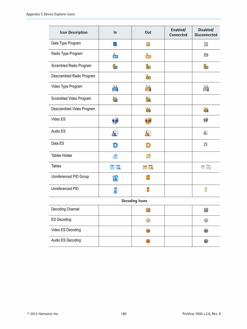
Appendix C Device Explorer Icons
© 2012 Harmonic Inc. 180 ProView 7000 v.2.6, Rev. A
Data Type Program
Radio Type Program
Scrambled Radio Program
Descrambled Radio Program
Video Type Program
Scrambled Video Program
Descrambled Video Program
Video ES
Audio ES
Data ES
Tables Holder
Tables
Unreferenced PID Group
Unreferenced PID
Decoding Icons
Decoding Channel
ES Decoding
Video ES Decoding
Audio ES Decoding
Icon Description In Out Enabled/Connected
Disabled/Disconnected

© 2012 Harmonic Inc. 181 ProView 7000 v.2.6, Rev. A
Appendix DFront Panel Menu Tree
Roo
t Men
u
Decoding
Alarms Table
Unit
Configuration
PCR Audio 1
Audio 2
Descrambling Video
Service Selection Mode
Programs
Reception
Routing and Descrambling
Status
Configuration
Status
MODCOD Roll Off
Symbol Rate Modulation Standard
Universal Band Frequency L-Band Frequency
Polarization LNB Frequency Band
LO Frequency 22 kHz Tone
Acquisition Mode Drift Compensation
Alarm Detailed Information
Input Selection
Management Port
Reset Unit
BOOTP
SW Version
HW Inventory
IP Configuration
MAC AddressAuto Negotiation
PHY Speed
IP AddressSubnet MaskDefault Gateway
Platform
Main Board
Front End Card
Bottom Options Card
GbE
Activation
Input Selection
Input Type
Output Selection
Descrambling
Date/Time
LCD Contrast
Restore to Defaults
IP Configuration
MAC Address
Admin Status
Auto Negotiation
PHY Speed
VBI/VANC
Presets
GbE Port 1
Active Port
SAT 1
SAT 2
SAT 3
SAT 4
GbE Port 2
MPE
Socket Configuration
Duplex Mode
TS 1
TS 2
TS 3
TS 4
Pilot Spectral Inversion
Attenuation Gain
Note: Some menus onlydisplay with certain hardware configurations.
Decoder1
Decoder2
DSRConfiguration
Status
CA Definitions
CAM 1
CAM 2
BISSCAM Association
Descrambling Mode
CAM MMI
Automatic Recovery Policy
Routing Table
Redundancy
PID Selection
Set Active Version
License

© 2012 Harmonic Inc. 182 ProView 7000 v.2.6, Rev. A
Appendix EProView 7000 Alarm List
The following table lists the ProView 7000 alarms and the information provided in the properties dialog.
Short Description Severity Corrective Action
Backup port activated Warning The backup port has been activated. It is recommended to revert to the primary port as soon as possible.
Backup port activated on GbE-2
Warning Revert to GbE-1.
BER Too High Warning Verify reception conditions and wiring.
CAM Descrambling Failure
Major Re-insert the CAM Reset the CAM If the problem persists, contact your CAM vendor.
CAM Missing in Slot Major Verify that the CAM is inserted properly.
CAM Processing Failure Major No bitrate was detected after the CAM.Verify: The input bitrate does not exceed the CAM limit The CAM supports the number of descrambled programs. If the problem persists please contact your CAM vendor.
Carrier Not Detected Critical No carrier was detected in the configured frequency.Verify that the RF Cable is properly connected and that the following is properly configured: Carrier Frequency LNB Configuration Acquisition mode
CC errors on Backup Port Warning CC errors have been detected on the backup port.Improve reception conditions.
CC errors on Primary Port Major CC errors detected on the primary port.Improve reception conditions.
Critical High Temperature Detected
Critical Verify:1. Make sure the fans are operating and are not blocked. 2. Turn off the device. 3. Contact Harmonic’s help desk.
Critical HW Card Failure Critical Contact Harmonic’s help desk
Critical SW Card Failure Major Contact Harmonic’s help desk.
Decoding Failure Major Contact Harmonic’s help desk.
De-Jittering Failure Major Refer to the de-jittering status indication.

Appendix E ProView 7000 Alarm List
© 2012 Harmonic Inc. 183 ProView 7000 v.2.6, Rev. A
Demodulation Failure Critical No carrier was detected in the configured frequency.Verify the following is properly configured: Modulation Standard Spectral Inversion MODCOD Frame Size Pilot Symbols Physical Layer Scrambling Seed
DSR not synced Major Verify that the relevant inputs are connected correctly. If the problem persists, contact the Harmonic help desk.
Eb/N0 Value Too Low Warning Verify reception conditions and wiring.
Embedded descrambler overflow
Major Reduce the bitrate or bypass the embedded descrambler.
ES Decoding Failure – Unsupported Content
Major Contact Harmonic’s help desk.
Ethernet Auto Negotiation Failure
Major Ethernet Auto-negotiation has failed.Verify that the cable if properly wired or consider reverting to manual PHY speed configuration.
Fan Failure Major Contact Harmonic’s help desk for further support.
Firmware download failure.
Warning Verify that the correct file was selected and there are no network disconnections.
Firmware upgrade failure. Previous version loaded.
Warning Upgrade again or revert to the previous version.
Frame Rate Mismatch. Warning The configured video frame rate does not match the frame rate of the source.Re-configure the decoding frame rate.
GbE Input Port Failed Critical Both GbE inputs failed. Verify that the cables are connected properly at both ends. Verify that the ports at both ends are enabled. Change the redundancy mode.
High Temperature Warning
Major Make sure the fans are operating and are not blocked, if the warning remains: 1. Turn off the device. 2. Contact Harmonic’s help desk.
Input bitrate overflow Major The input bitrate to the decoder is too high. Contact Harmonic’s help desk.
Input bitrate overflow on CAM
Major The input bitrate to the CAM is too high. Reduce the input bitrate. Contact Harmonic’s help desk.
Input failure Critical Both source inputs failed. Verify that the cables are properly connected on both ends Verify the reception conditions Consider adjusting the redundancy mode or triggers
Short Description Severity Corrective Action

Appendix E ProView 7000 Alarm List
© 2012 Harmonic Inc. 184 ProView 7000 v.2.6, Rev. A
Link down Major Link down has been detected on the GbE port.Check: That the cable is properly connected on both ends. That the ports on both ends are enabled.
Low delay stream while configured to normal mode
Warning Low delay stream received while decoder buffer management mode configured to normal mode. Configure the decoder buffer management mode to low delay.
MPEG Sync Loss Major The device cannot sync to the input stream.Verify that the input contains a valid MPEG transport stream.
MPEG Sync Loss on Backup Port
Warning The device cannot sync to the input stream.Verify that the input contains a valid MPEG transport stream.
MPEG Sync Loss on Primary Port
Major The device cannot sync to the input stream.Verify that the input contains a valid MPEG transport stream.
MPEG TS Input Overflow Major The input bitrate is too high.Contact Harmonic’s help desk.
MPEG TS Output Overflow
Major The Output bitrate is too high.Reduce the bitrate or contact Harmonic’s help desk.
No Genlock Sync Major The program cannot be decoded properly since the decoder could not sync to input Genlock signal.Verify that the Genlock input is properly wired and that the decoder display is configured correctly.
No PCR detected Warning This may cause AV sync issues.Check the PCR PID configuration.
Normal stream while configured to low delay
Warning Configure the decoder buffer management mode to Normal Delay.
Packet Loss Detected After CAM
Major Packets were dropped by the CAM.Verify: The input bitrate does not exceed the CAM limit The CAM supports the number of descrambled programs. If the problem persists please contact your CAM vendor.
PER Too High Warning Verify reception conditions and wiring.
PID conflict Major More than one PID is mapped to the same output PID. Check the output configuration.
PID Missing on Backup Port
Warning No bitrate detected on this PID. Problem originating up stream.
PID Missing on Primary Port
Major No bitrate detected on this PID. Problem originating up stream.
Program Descrambling Failure (output, Program #)
Major Verify that the number of programs descrambled is supported by the CAM or contact your CAM vendor.
Voltage Error Critical Contact Harmonic’s help desk.
Short Description Severity Corrective Action

© 2012 Harmonic Inc. 185 ProView 7000 v.2.6, Rev. A
Appendix FSoftware Management
F.1 Active Version ManagementThe ProView 7000 keeps the current and last software versions. The EMS enables you to choose the active software version. The process of changing the active software version takes several minutes and requires a reboot.
To open the Active Software Management dialog: Select Tools > Firmware > Set Active Software….
The Active Software Management dialog displays two software versions available. The currently active version radio button is marked.
To change the device software version: Select the second version and click Set Active Version.
NOTE: A software version that is invalid is indicated in its radio button as N/A and is disabled.

Appendix F Software Management Software Upgrade Manager
© 2012 Harmonic Inc. 186 ProView 7000 v.2.6, Rev. A
F.2 Software Upgrade ManagerUse the EMS Software Upgrade Manager to perform a software version upgrade for all selected devices.
CAUTION: The BOOTP software upgrade option should be turned off when using the EMS to upgrade the ProView 7000 device. See 7.11.5 Device Software Upgrade Properties.
To open the Software Upgrade Manager: Select Tools > Firmware Software Upgrade Manager.
The Software Upgrade manager enables you to select the update file source.
The manager lists all ProView 7000 devices currently managed by the EMS and provides a checkbox to the left of each device name for you to select which devices to upgrade.
The manager lists the following information for each device:
Device communication status (color coded): Disconnected (gray) No communication (red marked) Not logged-in (half red marked) Communicating (full colors)
Device IP, Serial number and Version number. Upgrade status (idle or active), % of upgrade done and upgrade time.
At the right of the Software Upgrade manger dialog, a group of buttons are provided to manage the upgrade operation:
[Start Upgrade] button – starts the upgrade session. [Remove] button – remove a device from the displayed list. [Select all] button – selects all devices for upgrade. [Unselect all] – clear all devices from upgrade. [Log…] button – displays the upgrade log. [Close] button – closes the upgrade dialog.

Appendix F Software Management Software Upgrade Manager
© 2012 Harmonic Inc. 187 ProView 7000 v.2.6, Rev. A
F.2.1 Upgrading the Firmware of ProView 7000s
It is recommended to upgrade all ProView 7000s at the same time. A device must be connected to be able to upgrade it, see 6.7 Connecting a Device. Once the device upgrade is successfully completed, the devices reboot and EMS closes. It takes several minutes to upgrade a device. The new version loads into the inactive firmware slot and does not replace the active version.
To upgrade the firmware of several ProView 7000s:1. Select Tools > Firmware Software Upgrade Manager.
The Software Upgrade Manager dialog displays.2. Mark the Upgrade checkboxes of the devices that you want to upgrade.
—or— To upgrade many devices:a. Click Remove to remove device names that are not part of the upgrade.
b. Click Select All to select all devices in the list.
3. Open the Upgrade File browser and browse to the zip file containing the new software on your local hard disk.
4. Click Select.5. Click Start Upgrade.6. When the upgrade is complete, wait a few minutes for devices to reboot then upgrade
your EMS installation to the same version of the managed devices:a. Refresh the web page with the ProView 7000 IP address.b. Click Launch ProView 7000 EMS on the ProView 7000 web page to install the EMS.
To upgrade your EMS installation to the same version of the managed devices:1. Run a web browser and enter a ProView 7000 IP address.
The initial ProView 7000 dialog displays.2. Click Launch ProView 7000 EMS on the ProView 7000 web page to install the EMS.
The EMS application installs.
F.2.2 Viewing the Software Upgrade Log
To view the software upgrade log:1. Select Tools > Firmware Software Upgrade Manager.
The Software Upgrade Manager dialog displays.2. Click Log.
The Activity Log dialog displays.

Glossary
Numerics A B C D E F G H I J L M N O P Q R S T U V W Y
© 2012 Harmonic Inc. 188 ProView 7000 v.2.6, Rev. A
Glossary
Numerics 10BASE-T
An IEEE standard, sometimes called “Ethernet,” that uses a twisted pair cable, with RJ-45 connectors, often connected in a star configuration through a hub. The maximum allowable cable length is 328 feet. A 10BASE-T system operates at 10 Mbps. See also 100BASE-T.
100BASE-T
An IEEE standard, sometimes called “Ethernet,” that supports data rates up to 100 Mbps, also known as Fast Ethernet. 100BASE-T uses twisted pair cable. See also 10BASE-T.
3:2 pulldown
A method that converts 24 frames per second motion picture film frame rate material to 30 frames per second interlaced video frame rate. This process is normally done by a telecine. It refers to using two film frames to generate five video fields of interlaced video (1080i or 480i). The first frame is scanned three times to generate three video fields, the second frame is scanned twice to generate two video fields, and the cadence continues. Note that every fifth frame will have images from different film frames. These are termed “dirty frames” as there may be significant differences in the two fields of video. The 3:2 process can also be applied for 720P progressive video, this results in a 2:3 cadence of video frames, without the “dirty frame” artifacts.
4:2:0
A component digital system that subsamples chroma components both vertically and horizontally by a factor of two with respect to luma.
A AAC LC
Advanced Audio Codec Low Complexity.
AC-3
Also known as Dolby Digital.
ACM
A card for the MN20 multiplexer. The ACM supports DES and DVB protocols.
adapter
A circuit board in a Harmonic encoder. Adapters have input or output ports. Also known as a card or a blade.

Glossary
Numerics A B C D E F G H I J L M N O P Q R S T U V W Y
© 2012 Harmonic Inc. 189 ProView 7000 v.2.6, Rev. A
AFD
Active Format Description. Signaling describes certain spatial characteristics of a high definition or standard definition video image. AFD and Bar Data are intended to be broadcast with the video signal that they describe. AFD information is intended to assist DTV displays in optimizing the displayed images. AFD may also be used by intermediate professional video equipment in conversion of video images of one aspect ratio into an image of another aspect ratio. Bar Data information is used to signal the precise unused areas of active video when the active image does not completely fill the picture area, in particular widescreen cinema material carried letterboxed in a frame with bars top and bottom. AFD is documented by SMPTE 2016 (multiple part document) and its carriage in compressed video is documented in DVB/ETSI TS 101 154, ATSC A/53 Part 4, ATSC A/72 Part 1, SCTE 128, and other standards.
AGC
Automatic Gain Control. Keeps the output signal of a circuit constant while the input signal amplitude varies.
Alarm Indicator
Displayed in the title bar of each web client page of the device. It appears in red when an alarm is issued and notifies of a fault and of its nature.
AMOL
Automated Measurement of Lineups
ARP
Address Resolution Protocol. Used for communications between network devices. See BOOTP.
ASI
Asynchronous Serial Interface. A DVB-defined electrical interface for carrying MPEG-2 transport streams at a defined transmission rate within a 270 Mbps carrier.
ATSC
Advanced Television Systems Committee. Establishes standards for digital terrestrial television system in the US and other countries.
Bbalanced audio
Audio that is transmitted differentially, that is, sending the positive and negative signals of an audio waveform so that the audio arrives undistorted because noise is cancelled out. See also unbalanced audio.
bandwidth
The maximum amount of data that a transmission device (cable, fiber-optics link, satellite feed, and so on) is capable of carrying.
BER
Bit Error Rate. The ratio of bits transmitted in error to the total bits sent. For example, a BER of 106 means 1 bit in a million is received in error.
Glossary
Numerics A B C D E F G H I J L M N O P Q R S T U V W Y
© 2012 Harmonic Inc. 190 ProView 7000 v.2.6, Rev. A
BISS
Basic Interoperable Scrambling System. An open standard for protecting digital contribution applications.
Bit rate
The average bitrate of the bit stream, in bits per second, during the sampling period.
Black video
A video signal where there is no luminance or chrominance information. Either intentionally created for a short period of time or the result of a failure in a transmission system.
BNC
A standard coaxial cable connector named for the inventors (Neill and Concelman) and the connection type (bayonet).
BOOTP
Bootstrap Protocol. Used to supply hosts with IP addresses and a TFTP boot file name. BOOTP requests and replies are encapsulated in a User Datagram Protocol (UDP) packet. The BOOTP server uses an address resolution protocol (ARP) cache to map MAC addresses to IP addresses. When the server receives a BOOTP request from a MAC address listed in its cache, the server sends a reply to the MAC address.
C CA
Conditional Access. Provides operator control over customer access to broadcast materials.
CA Descriptor
A descriptor which may be added to the PMT and identifies the CA system and other information related to that system.
CAM
Acronym for CA Module and is a standardized card which is used to unscramble services.
carrier frequency range
For a receiver, the range of valid input signals.
CAS
Conditional Access System. Scrambles the programming material and allows conditional access to the descrambled information on the basis of subscriber authorization. In consumer applications, CAS allows access to certain programs on the basis of a monetary exchange. In commercial applications, CAS allows controlled access to proprietary programs.
CAT
Conditional Access Table. The CAT informs the receiver of conditional access system (CAS) information, such as the EMMstream for provisioning the receiver.

Glossary
Numerics A B C D E F G H I J L M N O P Q R S T U V W Y
© 2012 Harmonic Inc. 191 ProView 7000 v.2.6, Rev. A
CC
Closed Captions or Continuity Counter. Readers are cautioned to avoid use of this abbreviation unless it is clearly stated in context.
CEA
Consumer Electronics Association.
CEA-608
Line 21 Data Services.
CEA-708
Digital Television (DTV) Closed Captioning.
chroma
The color difference component of the video signal. Sometimes termed “chrominance.” See also luma.
closed captioning
The process of encoding, transmitting, decoding, and displaying program-related text typically on the lower part of a monitor or television during broadcast. See CEA-608 and CEA-708 standards.
component
A portion of a signal or system.
Configuring
Defining the parameters of platform, input and output ports.
crosstalk
The interference of a signal from an adjacent signal.
Cue Tone
A sequence of audio tones (typically DTMF tones) used to prompt an action.
D DB-9
A 9-pin connector used to connect communications and other electronic devices. It is commonly used for TIA-232 and similar interfaces.
dBm
Power ratio in decibels (dB) of the measured power referenced to one milliwatt.
DD
Dolby Digital. See AC-3.
decoder
A device that converts an compressed signal back to baseband video and audio.

Glossary
Numerics A B C D E F G H I J L M N O P Q R S T U V W Y
© 2012 Harmonic Inc. 192 ProView 7000 v.2.6, Rev. A
downstream
The direction of the communications service data flow. Broadcast services flow downstream from the service provider to the subscriber.
DPI
Digital Program Insertion. Also referred to as Splicing, is the process in which the main feed is spliced to allow the insertion of another stream, usually an ad.
DSR
Deterministic SFN Re-multiplexing
DTS
Decoding Time Stamp. An MPEG-2 defined field that can be present in the PES packet header to indicate the time the access unit is decoded in the system target decoder.
DTV
Digital Television.
dual channel
A channel that consists of two audio signals that are not related to each other, for example, the English and Japanese translation of a program’s audio.
DVB
Digital Video Broadcasting project of the EBU. Specifies transmission and related standards for Europe (primarily) as well as other parts of the world.
DVB-ASI
DVB Asynchronous Serial Interface. A 270 Mbps serial interface to carry MPEG-2 Transport Stream.
DVB-CI
Digital Video Broadcasting – Common Interface
DVB-S
Digital Video Broadcasting - Satellite.
DVB-S2
Digital Video Broadcasting - Satellite - second generation.
E ECM
Entitlement Control Message. An ECM is a message generated by the conditional access system ( CAS). The ECM contains an encrypted version of the control word that only authorized subscribers can decrypt. See also EMM.

Glossary
Numerics A B C D E F G H I J L M N O P Q R S T U V W Y
© 2012 Harmonic Inc. 193 ProView 7000 v.2.6, Rev. A
EIA
Electronic Industries Alliance. A U.S. trade organization that was once responsible for establishing hardware interface standards. The EIA broke apart into several more specialized standards development organizations (SDOs) including the CEA and TIA. This break-up resulted in the renaming of a number of key standards (such as CEA-708 and TIA-232) which has caused industry confusion. Harmonic is careful to use the current and correct names of relevant standards.
EIT
Event Information Table. This table provides information in chronological order for the events contained within each service.
elementary stream
The basic raw output of either video or audio compression, not intended for physical manifestation beyond the creating device. Each elementary stream will be carried in a sequence of PES packets with a single PID within the eventual TS.
embedded controller
A processing unit located within each component that is responsible for the control of that component.
EMM
Entitlement Management Message. An EMM is a message generated by the conditional access system ( CAS). The EMM authorizes an individual subscriber or group of subscribers to descramble a program. The EMM is used with the ECM. See also ECM.
ES
Elementary Stream.
Ethernet
A data link (physical interface) developed for local area networks (LANs) that supports transmission rates up to 10 Mbps. Fast Ethernet supports transmission rates up to 100 Mbps. See also 10BASE-T and 100BASE-T.
Event
A user defined portion of a program which may be either “long form” (the program itself) or “short form” (also known as an interstitial), which might be advertising or promotion.
F F connector
A common coaxial cable connector used in cable systems and homes to connect antennas, televisions, and VCRs. Standardized in SCTE 124.
FCC
Federal Communications Commission. A U.S. governmental body that regulates electronic communications within the U.S.

Glossary
Numerics A B C D E F G H I J L M N O P Q R S T U V W Y
© 2012 Harmonic Inc. 194 ProView 7000 v.2.6, Rev. A
FEC
Forward Error Correction. An encoding technique that permits the correction of data which has received errors on the receiving end.
firmware
Embedded software that is stored in read-only memory. Firmware can consist of startup routines and other functions that are stored on memory devices such as ROMs, PROMs, and EPROMs.
FTA
Free To Air.
G gain
The amount of increase that an amplifier provides to the output side of a circuit.
GbE
Gigabit Ethernet. A transmission technology based on the IEEE Ethernet frame format and protocol used in local area networks that provide a data rate of 1 billion bits per second.
GMT
Greenwich Mean Time. The time in Greenwich, England, which is the location of the prime meridian (0 degrees longitude). All time zones are referenced to this meridian.
GOP
Group Of Pictures. An MPEG-2 video coding structure, a GOP may be either “open” or “closed”. Note that AVC does not define a GOP by itself, but has equivalent structural constructs.
H HD
High Definition.
HDD
Hard disk drive.
HE AAC
High Efficiency Advanced Audio Codec.
header
Several bytes at the beginning of a packet that determine the identification of the packet, possibly the type of data and other attributes within the packet.
Hertz (Hz)
A unit of frequency defined as one cycle per second. Abbreviated Hz.

Glossary
Numerics A B C D E F G H I J L M N O P Q R S T U V W Y
© 2012 Harmonic Inc. 195 ProView 7000 v.2.6, Rev. A
Hz
See Hertz (Hz).
I IEEE
Institute of Electrical and Electronics Engineers. The IEEE is a professional organization that develops a wide variety of standards. The IEEE 802 family of standards defines Ethernet and related communication systems.
IGMP
Internet Group Management Protocol.
input transport
Also known as a source transport, it contains all input devices for a transport in a single, easy-to-use place. Input devices can include video tape decks, satellite feeds, and so on.
IP
Internet Protocol.
IP address
An identifier for a computer or device on an Internet Protocol (IP) network. Networks using IP route messages based on the IP address of the destination. An IP address is a 32-bit number written in dotted decimal notation: four 8-bit sections, separated by periods, converted from binary to decimal. Each section is a number from zero to 255.
IRD
Integrated receiver decoder. A device that combines the capability of receiving satellite transmissions and decoding MPEG-2 transport stream packets.
ISI
Input Stream Identifier
ISO index value
A pointer value into the list of language abbreviations documented in ISO-639. Current values are online at http://www.loc.gov/standards/iso639-2/langhome.html.
ITU
International Telecommunication Union, a United Nations organization facilitating standardization of telecommunications and radio/television. It issues documents from either group as “ITU-T” or “ITU-R” recommendations.
J joint stereo
Joint stereo signals have a high degree of commonality between the left and right signals which can improve the amount of compression.

Glossary
Numerics A B C D E F G H I J L M N O P Q R S T U V W Y
© 2012 Harmonic Inc. 196 ProView 7000 v.2.6, Rev. A
LLC
A term meaning either “low complexity” (in the case of AAC audio coding) or a high-density optical connector used for single-mode and multimode fiber-optic applications.
LNA
Low Noise Amplifier. The preamplifier mounted at the focus of a parabolic antenna and which amplifies the received signal for a downconverter mounted nearby which then feeds an earth station receiver. It is designed to contribute the least amount of thermal noise to the received signal.
LNB
Low Noise Block downconverter. A combination low noise amplifier and downconverter built into one device. An LNB is usually located at the center of the satellite dish.
LSD
Low Speed Data.
luma
The brightness of the video signal. This term is preferred over “luminance” for video signals. See also chroma.
MMAC
Media Access Control. As defined by IEEE 802, the MAC provides the lower portion of the datalink layer, which is the OSI layer that is responsible for data transfer across a single physical connection, or series of bridged connections, between two network entities. The MAC differs for various physical media.
MAC address
The permanent identifier for a device. It consists of six octets separated by colons, for example, 00:20:A3:xx:xx:xx. The first six characters identify the manufacturer. Harmonic assigns the next six characters as a unique device identifier.
Mbaud
Megabaud, which is the signal rate of a line, expressed in millions. It can also be the switching speed, or number of transitions (voltage or frequency changes), per second.
monaural
A channel that has a single audio signal.
MPE
A PID which can contain anything.

Glossary
Numerics A B C D E F G H I J L M N O P Q R S T U V W Y
© 2012 Harmonic Inc. 197 ProView 7000 v.2.6, Rev. A
MPEG
Moving Picture Experts Group. A joint working group of the International Standards Organization and International Electrotechnical Committee. Some portions of the MPEG Standards have also been prepared jointly with the ITU-T.
MPEG-2
A family of specifications developed originally for compression of studio television at 24-, 25-, and 30-Hz frame rates. The system layer has support for additional functionality, including tolerance to errors, which makes it generally more suitable for transmission than MPEG-1.
MPEG-4
A family of specifications developed originally for video games. The original video coding specification has been supplanted by AVC, MPEG-4 Part 10 (also known as H.264), which provides significant compression efficiencies over MPEG-2 video coding. Also includes AAC/HE AAC audio coding specifications.
MPTS
Multiple Program Transport Stream. Several MPEG programs multiplexed together into a single Transport Stream.
multiplex
The ability to combine multiple signals over a single communications line or channel.
multiplexer
A function where multiple signals are combined into a single signal. A device that merges several lower-speed transmissions into one high-speed transmission, and vice versa. See also remultiplexer. Note that multiplexing functionality is usually built into encoders.
NNIC
Network Interface Card.
NIT
Network Information Table. This table conveys information about the physical organization of the transport streams and the characteristics of the network. The NIT is partially documented by MPEG-2 Systems and partially by DVB/ETSI EN 300 468. See also SI.
NMX
The NMX Digital Service Manager provides configuration, control, monitoring, and fault management for open digital television broadcast systems. NMX supports geographically diverse sites through a server/client architecture, and scales to support small or large networks.
Noise level
The indication of noise in a signal, where a higher value means more noise.
NTP
Network Time Protocol. Allows you to synchronize the clock of the device with the network clock.

Glossary
Numerics A B C D E F G H I J L M N O P Q R S T U V W Y
© 2012 Harmonic Inc. 198 ProView 7000 v.2.6, Rev. A
NTSC
National Television Systems Committee. This committee created the analog composite television standard once used in the United States, Japan, and several other countries. The standard transmits 525 lines at 29.97 (30/1.001) fields per second (interlaced) in the United States, Canada, and Mexico, and 525 lines at 30 fields per second (interlaced) in Japan. See also ATSC.
NVRAM
Non-Volatile Random Access Memory. NVRAM is usually implemented using static RAM with a battery backup system, which enables it to retain data after the power is turned off.
O
Ppacket
A block of data used for transmission.
PAL
Phase Alternate Line. The analog composite television standard used in much of Europe and Asia. PAL transmits 625 lines per frame at 25 frames per second using interlaced scanning.
PAT
Program Association Table. This table indicates the location (the PID values of the transport stream packets) of the corresponding Program Map Table ( PMT), as well as the location of the Network Information Table ( NIT).
PCR
Program Clock Reference. This is a field defined by MPEG-2 Systems, which carries a sample of the encoder’s 27-MHz reference clock. The PCR values are periodically inserted into the Transport Stream, and used by the decoder to reconstruct the clock and maintain synchronization with the encoder.
PER
Packet Error Rate.
PES
Packetized Elementary Stream. The MPEG-2 data structure used to carry elementary streams over physical media. The PES packet payload consists of data from a single elementary stream.
physical address
See MAC address.
PID
Packet Identifier. Integer values used in the MPEG-2 Systems standard to identify each elementary stream within a program within a transport stream.
PMT
Program Map Table. An MPEG-2 Program Specific Information ( PSI) table that maps the PID values to each elementary stream (and stream type) that comprises the program.

Glossary
Numerics A B C D E F G H I J L M N O P Q R S T U V W Y
© 2012 Harmonic Inc. 199 ProView 7000 v.2.6, Rev. A
port
A port is an input to or an output from a component, an adapter, or a module.
program
In MPEG-2 Systems, a program is a collection of video, audio, and data elementary streams carried in a TS that share a common clock reference.
PSI
Program Specific Information. A set of MPEG-2 inband control tables. The tables contain tuning information, information about the relationships between the various elementary streams, and conditional access information. See also SI.
PSIP
Program and System Information Protocol
PTS
Presentation Time Stamp. An MPEG-2 defined field that can be present in the PES packet header to indicate the time the access unit is to be presented (displayed) to the viewer.
QQAM
Quadrature Amplitude Modulation. Transmits 4 bits (16 QAM) to 8 bits (64 QAM) at the same time by varying the phase and amplitude of a signal. See also QPSK.
QPSK
Quaternary Phase Shift Keying. QPSK transmits 2 bits at the same time by varying the phase of the signal. See also QAM.
RRedundancy
A back-up system of Harmonic components that ensures uninterruptible service in the event of a component failure.
Reed-Solomon decoder
A device that performs error correction on the incoming data stream.
reference clock
The 27-MHz abstract clock from which various physical clocks are instantiated. The encoder maintains a 27 MHz encoder clock, and via correct placement of PCR values into the Transport Stream, the decoder is able to reconstruct the reference clock in the form of a decoder clock.
reference level
Reference level is the nominal level to which all parts of an audio signal chain are aligned. This is commonly +4 dBu or 0 dBu for analog audio systems. It is measured in an out of service measurement where a sine-wave tone of the nominal level is introduced at the entrance of the system and then the

Glossary
Numerics A B C D E F G H I J L M N O P Q R S T U V W Y
© 2012 Harmonic Inc. 200 ProView 7000 v.2.6, Rev. A
output of each device in the chain is checked in turn versus the nominal level. This is an analog concept and measurement. The setting permits the encoder to adjust its gain structure to ensure that the resulting digital audio level for a sine-wave tone at Reference Level will be 20 dBFS.
In the digital domain the Facility Reference Level should be equivalent to -20 dBFS (decibels below Full Scale) per SMPTE RP155.
remultiplexer
A component that multiplexes several MPEG-2 SPTS input streams into a single MPTS output stream.
RJ-45
Also RJ45. An eight-wire connector such as an Ethernet connector. See also 10BASE-T and 100BASE-T.
roll-off factor
The amount of bandwidth used in excess of the baud rate.
SSD
Standard Definition.
SDI
Serial Digital Interface.
SDT
Service Description Table. This DVB table describes services contained within a particular transport stream. The services might be part of the actual transport stream or part of other transport streams, which the table_id identifies. See also SI.
SI
Service Information. A set of standardized tables that supplements MPEG PSI. These tables (for DVB) include the BAT, NIT, SDT, EIT, RST, and TDT. ATSC PSIP is also SI.
single channel
See monaural.
SMPTE
Society of Motion Picture and Television Engineers, primary creator of motion imaging standards for TV, digital cinema, and film.
SMPTE 334-1
Society of Motion Picture and Television Engineers – Vertical ancillary data mapping of caption and related data.
SMPTE 334-2
Caption Distribution Packet (CDP) Definition.

Glossary
Numerics A B C D E F G H I J L M N O P Q R S T U V W Y
© 2012 Harmonic Inc. 201 ProView 7000 v.2.6, Rev. A
SNMP
Simple Network Management Protocol. The protocol that Harmonic control and management systems use to configure and monitor Harmonic devices remotely over IP.
SNR
Signal-to-Noise Ratio. The ratio of the amplitude (power, volume) of a data signal to the amount of noise (interference) in the line. It measures the clarity and quality of a transmission channel or electronic device, usually in decibels.
Socket
An additional qualifying value for an IP address used by the UDP protocol.
SPTS
MPEG-2 Single Program Transport Stream.
SR
Symbol Rate.
status bar
The status bar, usually located at the bottom of the application window, indicates the current selection and displays explanatory text for toolbar and menu selections.
STB
Set Top Box.
STC
System Time Clock. This clock is the common 27-MHz clock that is used to create both PCRs and system clock references (SCRs).
stereo
A stereo signal consists of two audio signals that are directly related to each other, one signal representing the left side of the soundfield and the other the right side.
subnet mask
A subnet mask is a bit combination used to describe which part of an address refers to the network or the subnet, and which part refers to the host or destination device.
symbol rate
The encoded transmission rate in a modulated stream, expressed in Mbaud.
TTCP
Transmission Control Protocol.
TDT
Time and Date Table. This DVB-SI table contains frequently updated information that relates to the present time and date. See also SI.

Glossary
Numerics A B C D E F G H I J L M N O P Q R S T U V W Y
© 2012 Harmonic Inc. 202 ProView 7000 v.2.6, Rev. A
teletext
An electronic communications system in which printed information is broadcast by television signal to sets equipped with decoders.
TFTP
Trivial File Transfer Protocol. A simple form of the file transfer protocol (FTP). TFTP uses the user datagram protocol ( UDP). It is often used by servers to boot diskless workstations, X-terminals, and routers.
TIA-232
A TIA standard interface for connecting serial devices, such as modems, mice, and serial printers to a DTE. TIA-232 supports the 25-pin D-type connector (DB-25) and a 9-pin D-type connector (DB-9).
TOT
Time Offset table.
tp
transponder
transport
In NMX, a transport is a submap that exists within the main submap. It contains a collection of components and external devices as well as channels and circuits. The function of a transport is to contain a collection of Harmonic components, input devices, output devices, and links, and to provide access to the programs and circuits associated with that transport.
Transport Stream
One or more multiplexed compressed programs, typically containing video, audio, and associated data. Defined by MPEG-2 Systems (ISO/IEC 13818-1), it can transport a wide variety of video and audio compression formats.
TS
Abbreviation for Transport Stream, defined by MPEG-2 Systems (ISO/IEC 13818-1)
TS packet
MPEG-2 Transport Stream packet. The basic unit of an MPEG-2 Transport Stream. Each packet is 188 bytes, which includes a 4-byte header.
UUDP
User Datagram Protocol. A connectionless protocol that relies on IP transport. Unlike TCP/IP, UDP/IP provides no error recovery services, offering instead a faster way to send and receive datagrams over an IP network.
UDP port
User Datagram Protocol used with GbE interface.

Glossary
Numerics A B C D E F G H I J L M N O P Q R S T U V W Y
© 2012 Harmonic Inc. 203 ProView 7000 v.2.6, Rev. A
unbalanced audio
Audio that has a single output with respect to ground; that is, the output is not transmitted differentially. See also balanced audio.
Uploading configuration
Sending the configuration to the device.
VVANC
Vertical Ancillary data space. During the vertical interval of each field or frame, the ancillary data space located between SAV and EAV markers. Digital information can be transmitted efficiently in VANC (as opposed to VBI), since only the direct bits are sent. There are SMPTE standards documenting the carriage of most services originally carried in VBI.
VBI
Vertical Blanking Interval. This is the space between the end of the vertical synchronization pulses and start of the active video (lines 10 to 21 for NTSC, and lines 6 to 22 for PAL). Digital information can be transmitted during this time when encoded as waveforms. Examples of signals transmitted in the VBI include teletext, AMOL, and CEA-608 closed captions.
VI
Video Index
WWSS
Wide Screen Signaling. WSS is an analog waveform carried in Line 23 of a 625-line (PAL) video signal. As a type of VBI signaling, it conveys the aspect ratio of the image, and can be used by WSS-capable televisions to determine the correct display mode. For example, standard (4:3), widescreen (16:9), or <letterbox> (16:9 on 4:3). Strictly speaking. It is being obsoleted by AFD over time.
YY (luminance)
Brightness component of a video signal.
YUV
YUV component signals used by analog composite systems. The Y is the luma component, U and V are color difference components scaled for proper encoding into the composite signal. All three components are derived from RGB.

Harmonic Inc.4300 North First St.San Jose, CA 95134, U.S.A.T +1 408 542 2500 F +1 408 490 6770
www.harmonicinc.com
© Copyright January 2012 Harmonic Inc. All rights reserved. Manual Part No. MAN-PVR-7K-2.6