ptv series · ptv manual 118013-001 rev b ptv series spellman’sptvseriesofmodularhighvoltagepower...
TRANSCRIPT
R
High SPELLMAN HIGH VOLTAGE ELECTRONCORPORATION 475 Wireless Blvd. Hauppauge, New York, 1178 +1(631) 630-3000*FAX: +1(6E-mail: [email protected]: www.spellmanhv.co
PTV MANUAL
PTV SERIES
Voltage Power Supply MODEL : SERIAL# : DATE :
ICS
8
31) 435-1620* om m
118013-001 Rev B
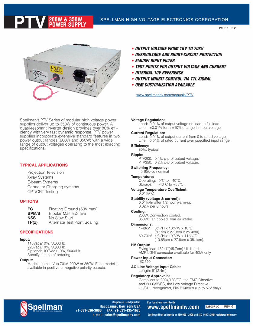
Spellman’s PTV Series of modular high voltage powersupplies deliver up to 350W of continuous power. Aquasi-resonant inverter design provides over 80% effi-ciency with very fast dynamic response. PTV powersupplies incorporate extensive standard features in twopower output ranges (200W and 350W) with a widerange of output voltages operating to the most exactingspecifications.
TYPICAL APPLICATIONS
Projection TelevisionX-ray SystemsE-beam SystemsCapacitor Charging systemsCPT/CRT Testing
OPTIONS
FG Floating Ground (50V max)BPM/S Bipolar Master/SlaveNSS No Slow StartTP(x) Alternate Test Point Scaling
SPECIFICATIONS
Input:115Vac±10%, 50/60Hz.220Vac±10%, 50/60Hz.Optional: 100Vac±10%, 50/60Hz.Specify at time of ordering.
Output:Models from 1kV to 70kV, 200W or 350W. Each model isavailable in positive or negative polarity outputs.
Voltage Regulation:Load: 0.01% of output voltage no load to full load.Line: ±0.01% for a ±10% change in input voltage.
Current Regulation:Load: 0.01% of output current from 0 to rated voltage.Line: 0.01% of rated current over specified input range.
Efficiency:80%, typical.
Ripple:PTV200: 0.1% p-p of output voltage.PTV350: 0.2% p-p of output voltage.
Switching Frequency:45-65kHz, nominal
Temperature:Operating: 0°C to +40°C.Storage: -40°C to +85°C.
Voltage Temperature Coefficient:0.01%/°C
Stability (voltage & current):0.01%/hr after 1/2 hour warm-up.0.02% per 8 hours.
Cooling:200W: Convection cooled.350W: Fan cooled, rear air intake.
Dimensions:1-40kV: 33/16”H x 103/4”W x 10”D
(8.1cm x 27.3cm x 25.4cm).50-70kV: 43/16”H x 107/8”W x 1113/16”D
(10.65cm x 27.6cm x 35.1cm).HV Output:
Flying lead 18”±1”(45.7cm) UL listed.AMP LGHI connector available for 40kV only.
Power Input Connector:IEC320.
AC Line Voltage Input Cable:Length: 8’ (2.4m).
Regulatory Approvals:Compliant to 2004/108/EC, the EMC Directiveand 2006/95/EC, the Low Voltage Directive.UL/CUL recognized, File E148969 (up to 5kV only).
• OUTPUT VOLTAGE FROM 1KV TO 70KV• OVERVOLTAGE AND SHORT-CIRCUIT PROTECTION• EMI/RFI INPUT FILTER• TEST POINTS FOR OUTPUT VOLTAGE AND CURRENT• INTERNAL 10V REFERENCE• OUTPUT INHIBIT CONTROL VIA TTL SIGNAL• OEM CUSTOMIZATION AVAILABLE
SPELLMAN HIGH VOLTAGE ELECTRONICS CORPORATIONPTV 200W & 350WPOWER SUPPLY
PAGE 1 OF 2
www.spellmanhv.com/manuals/PTV
Corporate Headquarters
Hauppauge, New York USA+1-631-630-3000 FAX: +1-631-435-1620
e-mail: [email protected]
www.spellmanhv.com 128007-001 REV. G
Spellman High Voltage is an ISO 9001:2008 and ISO 14001:2004 registered company
For locations worldwide
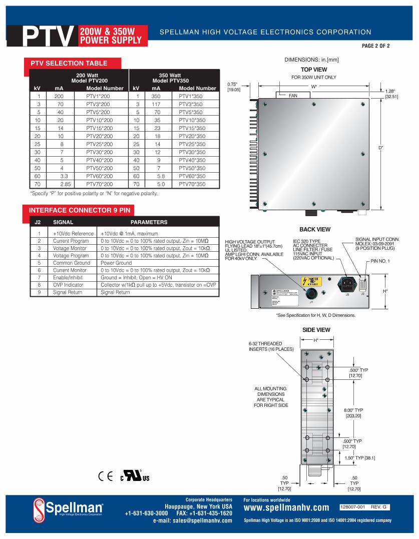
PTV SELECTION TABLE
200 Watt 350 WattModel PTV200 Model PTV350
kV mA Model Number kV mA Model Number
1 200 PTV1*200 1 350 PTV1*350
3 70 PTV3*200 3 117 PTV3*350
5 40 PTV5*200 5 70 PTV5*350
10 20 PTV10*200 10 35 PTV10*350
15 14 PTV15*200 15 23 PTV15*350
20 10 PTV20*200 20 18 PTV20*350
25 8 PTV25*200 25 14 PTV25*350
30 7 PTV30*200 30 12 PTV30*350
40 5 PTV40*200 40 9 PTV40*350
50 4 PTV50*200 50 7 PTV50*350
60 3.3 PTV60*200 60 5.8 PTV60*350
70 2.85 PTV70*200 70 5.0 PTV70*350
*Specify “P” for positive polarity or “N” for negative polarity.
D*
H*
W*FAN
0.75"[19.05] 1.28"
[32.51]
J1
J2J3
DANGERHIGH
VOLTAGE
SPELLMANHIGH VOLTAGE ELECTRONICS CORP.Plainview, NY 11803 MADE IN USA
PART NO:MODEL:SERIAL NO.OUTPUT:INPUT:
SIGNAL INPUT CONN.MOLEX: 03-09-2091(9 POSITION PLUG)
PIN NO. 1
IEC 320 TYPEAC CONNECTERLINE FILTER / FUSE115VAC INPUT(220VAC OPTIONAL)
TOP VIEW
BACK VIEW
8.00" TYP[203.20]
.500" TYP [12.70]
1.50" TYP [38.1]
.500" TYP [12.70]
.50TYP
[12.70]
.50TYP
[12.70]
ALL MOUNTING DIMENSIONSARE TYPICAL
FOR RIGHT SIDE
6-32 THREADEDINSERTS (16 PLACES)
SIDE VIEW
*See Specification for H, W, D Dimensions.
H*
FOR 350W UNIT ONLY
HIGH VOLTAGE OUTPUTFLYING LEAD 18"±1"(45.7cm)UL LISTED.AMP LGHI CONN. AVAILABLE FOR 40kV ONLY.
INTERFACE CONNECTOR 9 PIN
J2 SIGNAL PARAMETERS
1 +10Vdc Reference +10Vdc @ 1mA, maximum 2 Current Program 0 to 10Vdc = 0 to 100% rated output, Zin = 10MΩ3 Voltage Monitor 0 to 10Vdc = 0 to 100% rated output, Zout = 10kΩ4 Voltage Program 0 to 10Vdc = 0 to 100% rated output, Zin = 10MΩ5 Common Ground Power Ground6 Current Monitor 0 to 10Vdc = 0 to 100% rated output, Zout = 10kΩ7 Enable/Inhibit Ground = Inhibit, Open = HV ON 8 OVP Indicator Collector w/1kΩ pull up to +5Vdc, transistor on =OVP9 Signal Return Signal Return
DIMENSIONS: in.[mm]
SPELLMAN HIGH VOLTAGE ELECTRONICS CORPORATIONPTV 200W & 350WPOWER SUPPLY
PAGE 2 OF 2
Corporate Headquarters
Hauppauge, New York USA+1-631-630-3000 FAX: +1-631-435-1620
e-mail: [email protected]
www.spellmanhv.com 128007-001 REV. G
Spellman High Voltage is an ISO 9001:2008 and ISO 14001:2004 registered company
For locations worldwide
IMPORTANT SAFETY PRECAUTIONS
SAFETY THIS POWER SUPPLY GENERATES VOLTAGES THAT ARE DANGEROUS AND MAY BE FATAL.
OBSERVE EXTREME CAUTION WHEN WORKING WITH THIS EQUIPMENT.
High voltage power supplies must always be grounded.
Do not touch connections unless the equipment is off and the Capacitance of both the load and power supply is discharged.
Allow five minutes for discharge of internal capacitance of the power supply.
Do not ground yourself or work under wet or damp conditions.
SERVICING SAFETY .
Maintenance may require removing the instrument cover with the power on.
Servicing should be done by qualified personnel aware of the electrical hazards.
WARNING note in the text call attention to hazards in operation of these units that could lead to possible injury or death.
CAUTION notes in the text indicate procedures to be followed to avoid possible
damage to equipment.
Copyright © 2000, Spellman High Voltage Electronics Corporation. All Rights Reserved. This information contained in this publication is derived in part from proprietary and patent data. This information has been prepared for the express purpose of assisting operating and maintenance personnel in the efficient use of the model described herein, and publication of this information does not convey any right to reproduce it or to use it for
any purpose other than in connection with installation, operation, and maintenance of the equipment described.
118004-001 REV. B

WICHTIGE SICHERHEITSHINWEISE
SICHERHEIT DIESES HOCHSPANNUNGSNETZTEIL ERZEUGT LEBENSGEFÄHRLICHE HOCHSPANNUNG.
SEIN SIE SEHR VORSICHTIG BEI DER ARBEIT MIT DIESEM GERÄT.
Das Hochspannungsnetzteil muß immer geerdet sein.
Berühren Sie die Stecker des Netzteiles nur, wenn das Gerät ausgeschaltet ist und die elektrischen Kapazitäten des Netzteiles und der angeschlossenen Last entladen sind.
Die internen Kapazitäten des Hochspannungsnetzteiles benötigen ca. 5 Minuten, um sich zu entladen.
Erden Sie sich nicht, und arbeiten Sie nicht in feuchter oder nasser Umgebung.
Notwendige Reparaturen können es erforderlich machen, den Gehäusedeckel während des Betriebes zu entfernen.
Reparaturen dürfen nur von qualifiziertem, eingewiesenem Personal ausgeführt werden.
“WARNING” im folgenden Text weist auf gefährliche Operationen hin, die zu Verletzungen oder zum Tod führen können.
“CAUTION” im folgenden Text weist auf Prozeduren hin, die genauestens befolgt werden müssen, um eventuelle Beschädigungen des Gerätes zu vermeiden.
SERVICESICHERHEIT
118004-001 REV. B
PRECAUTIONS IMPORTANTES POUR VOTRE SECURITE
CONSIGNES DE SÉCURITÉ CETTE ALIMENTATION GÉNÈRE DES TENSIONS QUI SONT DANGEUREUSES ET PEUVENT ÊTRE FATALES.
SOYEZ EXTRÊMENT VIGILANTS LORSQUE VOUS UTILISEZ CET ÉQUIPEMENT.
Les alimentations haute tension doivent toujours être mises à la masse.
Ne touchez pas les connectiques sans que l’équipement soit éteint et que la capacité à la fois de la charge et de l’alimentation soient déchargées.
Prévoyez 5 minutes pour la décharge de la capacité interne de l’alimentation.
Ne vous mettez pas à la masse, ou ne travaillez pas sous conditions mouillées ou humides.
La maintenance peut nécessiter l’enlèvement du couvercle lorsque l’alimentation est encore allumée.
Les réparations doivent être effectuées par une personne qualifiée et connaissant les risques électriques.
Dans le manuel, les notes marquées « WARNING » attire l’attention sur les risques lors de la manipulation de ces équipements, qui peuvent entrainer de possibles blessures voire la mort.
Dans le manuel, les notes marquées « CAUTION » indiquent les procédures qui doivent être suivies afin d’éviter
d’éventuels dommages sur l’équipement.
CONSIGNES DE SÉCURITÉ EN CAS DE REPARATION
118004-001 REV. B
IMPORTANTI PRECAUZIONI DI SICUREZZA SICUREZZA
QUESTO ALIMENTATORE GENERA TENSIONI CHE SONO PERICOLOSE E POTREBBERO ESSERE MORTALI.
PONI ESTREMA CAUTELA QUANDO OPERI CON QUESO APPARECCHIO.
Gli alimentatori ad alta tensione devono sempre essere collegati ad un impianto di terra.
Non toccare le connessioni a meno che l’apparecchio sia stato spento e la capacità interna del carico e dell’alimentatore stesso siano scariche.
Attendere cinque minuti per permettere la scarica della capacità interna dell’alimentatore ad alta tensione.
Non mettere a terra il proprio corpo oppure operare in ambienti bagnati o saturi d’umidità.
SICUREZZA NELLA MANUTENZIONE.
Manutenzione potrebbe essere richiesta, rimuovendo la copertura con apparecchio acceso.
La manutenzione deve essere svolta da personale qualificato, coscio dei rischi elettrici.
Attenzione alle AVVERTENZE contenute nel manuale, che richiamano all’attenzione ai rischi quando si opera con tali unità e che potrebbero causare possibili ferite o morte.
Le note di CAUTELA contenute nel manuale, indicano le procedure da seguire per evitare possibili danni all’apparecchio.
118004-001 REV. B
PTV MANUAL i 118012-001 REV B
Table of Contents PAGE
1. INTRODUCTION 1.1 Description of the PTV Series .............................................................................1 1.2 PTV Specifications ..............................................................................................1 1.3 Standard Features.................................................................................................2 1.4 Options.................................................................................................................2 1.5 Interpreting the Model Number ...........................................................................2
2. INSPECTION & INSTALLATION 2.1 Initial Inspection ..................................................................................................3 2.2 Mechanical Installation........................................................................................3
3. OPERATING INSTRUCTIONS 3.1 Operation .............................................................................................................5 3.2 Standard Features.................................................................................................6
4. PRINCIPLES OF OPERATION 4.1 AC to DC Rectifier and Associated Circuits .......................................................10 4.2 High Frequency Inverter ......................................................................................10 4.3 High Voltage Circuits ..........................................................................................10 4.4 Control Circuits....................................................................................................11 4.5 Options.................................................................................................................11
5. OPTIONS 5.1 Floating Ground...................................................................................................12 5.2 220C AC Single Phase Input ...............................................................................12 5.3 No Slow Start.......................................................................................................12 5.4 Non-Standard Slow Start .....................................................................................12 5.5 Extra Length Output Cable ..................................................................................12 5.6 Focus ....................................................................................................................12 5.7 Grid ......................................................................................................................12 5.8 Custom Designed Models ....................................................................................12
6. MAINTENANCE 6.1 Periodic Servicing................................................................................................14 6.2 Performance Test .................................................................................................14 6.3 High Voltage Dividers .........................................................................................14
7. REPLACEMENT PARTS 7.1 Replacement Parts................................................................................................15 7.2 Correspondence and Ordering Spare Parts ..........................................................15 7.3 Recommended Spare Parts ..................................................................................16
PTV MANUAL ii 118012-001 REV B
8. FACTORY SERVICE 8.1 Warranty Repairs .................................................................................................17 8.2 Factory Service Procedures .................................................................................17 8.3 Ordering Options and Modifications ...................................................................17 8.4 Shipping Instructions ...........................................................................................17
APPENDIX A. Specification Controls (Custom Models Only)
PTV MANUAL 1 118012-001 REV B
Chapter 1
INTRODUCTION 1.1 Description of the PTV Series
he PTV series of high voltage power supplies provides very well regulated, low ripple high voltage in a highly efficient, compact design. The
dramatically reduced size of the PTV Module, compared to traditional high voltage modules, is obtained by a state of the art off-line resonant converter. The resonant converter utilizes a unique control scheme, which allows constant frequency operation while maintaining high efficiency. The high efficiency is obtained by zero current switching (ZCS) resonant control. High operating frequency, typically 60KHz, allows for very low ripple and excellent dynamic response capabilities.
The DC output voltage and current are controllable over the full range of operation. Monitoring and control signals are provided for simple, yet flexible control of the power supply. The PTV series operates from 115VAC +/- 10%, or 220VAC +/- 10%, at 50/60 Hz single phase. (User should specify input voltage at time of ordering). The PTV series operates at 200W continuous without the need for forced air cooling. The ambient temperature must be kept below the maximum rating as specified in 1.2. Consult Spellman Sales Department for higher power capabilities of the PTV series (up to 600W peak).
The standard warranty applies to the PTV modules. Consult factory about the warranty for custom PTV modules.
1.2 PTV Specifications Output Control: Voltage and current are externally
programmable over the entire range from zero to maximum rating via 0-10VDC reference or potentiometer. (Other scale factors for control and monitoring can be provided i.e. 1 volt per 10KV, 1 volt per 10mA etc.).
Input Voltage: 115Vac10%, 50/60Hz, single phase. (220VAC 10%, 50/60Hz, single phase, internally switchable). Consult factory for other than 115VAC input voltage.
Voltage Regulation: Load Regulation: 0.01% of full voltage for a no
load to full load change. Line Regulation: 0.01% of full voltage over the
specified input voltage range.
Current Regulation: Load Regulation: 0.05% 25uA from 0 voltage to
full voltage. Line Regulation: 0.01% of full current over the
specified input voltage range.
Ripple: 0.1% p-p of output voltage.
Polarity: Positive and Negative polarity with respect to ground. (Specify at time of ordering).
Stability: 0.02% per hour after 1/2 hour warm up.
Temperature Coefficient: 150 ppm per C.
Temperature:
Operating: 20C to +50C Storage: -40C to +80
Monitoring:
0-10VDC corresponding to 0-100% of output voltage. 1-10VDC corresponding to 0-100% of output current. (Other scale factors available).
Control: Logic level control for high voltage enable/disable.
IMPORTANT
This control signal in not a safety interlock and should not be used for
protection from high voltage generation for safety purposes.
T
PTV MANUAL 2 118012-001 REV B
1.3 Standard Features The PTV series incorporates several standard features designed to optimize user operation.
Slow Start: Provides a gradual increase in high voltage output until the maximum set point is reached. Various slow start times can be accommodated. Consult Spellman’s Sales Department for information on slow start options.
Overvoltage Protection: An overvoltage protection circuit monitors the output for excessive voltage generation. Overvoltage conditions can be caused by excessive input program signal or an internal defect in the control circuits. If an overvoltage condition is detected, the power supply is latched off until input power is reset.
Overvoltage Indication: An open collector signal is provided to give the user an indication that an overvoltage condition occurred.
Internal EMI Filter and Fuse Protection: An internal EMI filter and fuse provide protection against line voltage surges and power supply faults.
1.3.1 Remote Operating Features Remote Programming: Allows remote adjustment of the output voltage and current via an external voltage source.
Remote Monitor: Allows remote monitoring of the Output voltage and current.
High Voltage Enable/Disable: Allows remote ON/OFF control of the high voltage.
+10VDC Reference: A +10VDC reference is provided for remote programming via a potentiometer or resistive divider.
1.4 Options The options available are listed in Table 1.1. See section 5 for more information on the options along with operating and set-up instructions. With few exceptions, these options can be retrofitted to your power supply at
the factory in a short time. For price and retrofit arrangements, contact the Spellman Sales Department.
CODE DISCRIPTION
• FG Floating Ground
• 220 220VAC Single Phase Input
• NSS No Slow Start
• SS(X) Non-Standard Slow Start
• LL(X) Extra Length Output Cable
• Output Connector
• Focus Outputs
• Grid Outputs
1.5 Interpreting the Model Number:
The model number of the power supply describes its capabilities. After the series name is: (1) The maximum voltage in kilovolts. (2) The polarity of the output – positive (P),
or negative (N). (3) The maximum output in watts.
PTV 30 P 200/ FG / X(#)
SeriesName
VoltageMaximum
Polarity Option
"X" NumberCustom
PowerMaximum
(4) The option code for all options that are
included. (5) Custom “X” number representing details
listed in a separate specification control drawing.
PTV MANUAL 3 118012-001 REV B
Chapter 2
Inspection and Installation
nitial inspection and preliminary checkout procedures are recommended. For safe operation, please follow the step-by-step
procedures described in Chapter 3, Operating Instructions.
2.1 Initial Inspection Inspect the package exterior for evidence of damage due to handling in transit. Notify the carrier and Spellman immediately if damage is evident. Do not destroy or remove any of the packing material used in a damaged shipment. After unpacking, inspect the panel and chassis for visible damage.
Fill out and mail the Warranty Registration card accompanying the unit. Standard PTV200 high voltage power supplies and components are covered by warranty. Custom and special order models (with an X suffix in the model number) are also covered by warranty.
2.2 Mechanical Installation The PTV series module power supplies are designed for installation into existing or newly developed OEM equipment. The power supply can also easily fit into bench top applications or test set requirements. Standard unit dimensions are shown in Figure 2.1
For custom mounting requirements or specific package size requirements consult Spellman’s Sales Department. Spellman has many package designs available, or can design a specific enclosure for your requirements.
The PTV series utilizes solid encapsulations for corona free operation. No periodic maintenance is required. Lower voltage units (under 6KV) utilize air insulation. Due to conservative voltage spacing design, periodic maintenance is not required.
I
PTV MANUAL 4 118012-001 REV B
.500" TYP
B
J2
T 4A/250V - 115VT 2A/250V - 230V
J1
J3
Danger Label
Identification Label
FUSES
.500" TYP
8.00" TYP
1.50"TYP
.750 A
AMP: LGH4I Conn.High Voltage Output
or Flying Lead 24"(Customer Specified)
IEC 320 TYPEAC ConnectorLine Filter / Fuse115VAC Input(220VAC Optional)
Pin No. 1
Signal Input Conn.Molex: 03-09-2091(9 Position Plug)
All Mounting DimensionsAre Typical For Right Side
Heatsink
Max kV A B C
1-40kV 10.00 10.00 3.19
50-60kV 10.87 10.50 4.19
J2
TABLE 2.1 J2 WIRING
Pin No. FUNCTION
1 +10.35VoltsCurrent Program2Voltage Monitor3Voltage Program4Common Ground5Current Monitor6Enable7OVP Indicator8Control and Monitor RTN9
J2Pin No.
Orientation
1
4
78
5
2
9
6
3
.50"TYP
CHAUPPAUGE, NY 11788 MADE IN USAHIGH VOLTAGE ELECTRONICS CORP
6-32 Threaded
.50"TYP
Inserts (16 Places)
Figure 2.1 Unit Dimensions
PTV MANUAL 5 118012-001 REV B
Chapter 3
Operating Instructions
3.1 Operation WARNING
THIS EQUIPMENT GENERATES DANGEROUS VOLTAGES THAT MAY BE
FATAL. PROPER GROUNDING OF ALL HIGH VOLTAGE EQUIPMENT IS ESSENTIAL.
IMPORTANT: Before connecting the power supply to the AC line, follow this step-by-step procedure. Do not connect the power supply to the AC
line until Step G is reached. Failure to follow these procedures may void
the warranty. A) Insure that the high voltage cable is properly terminated to the load. Insure that all circuits connected to the high voltage output are safely interlocked against accidental contact. Insure external load is discharged.
B) Check the input voltage rating on the serial nameplate of the supply and make certain that this is the rating of the available power source. PTV modules operate on 115VAC unless ordered with a different input voltage option.
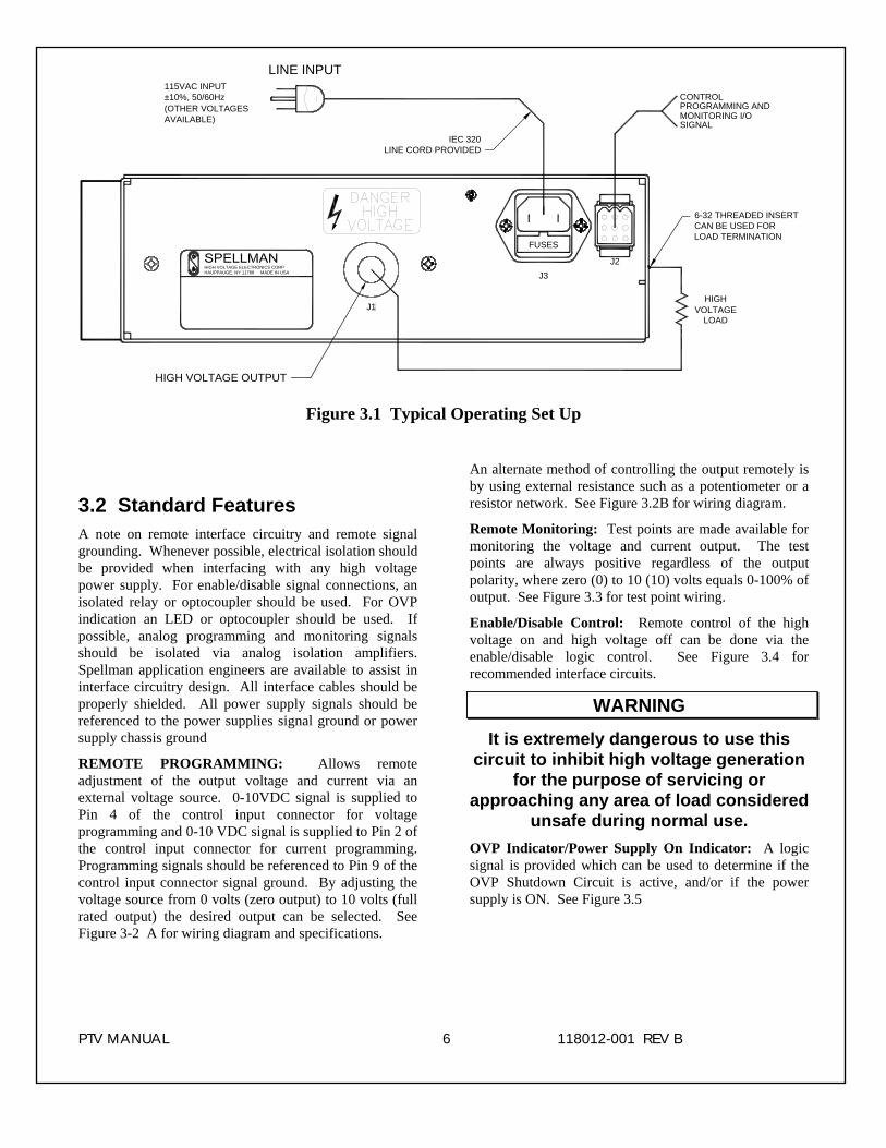
C) PROPER GROUNDING TECHNIQUE: The chassis of high voltage power supplies must be grounded, preferably to a water system ground using copper pipe or other earth ground. See Figure 3.1 for a typical operating setup. The return line from the load should be connected to the power supply chassis. Using a separate external ground at the load is not recommended. An IEC 320 connector is provided for connection to the line voltage source. A standard three prong line cord is also provided.
D) Options Note : See section 5 for hook up and operating instructions for the options on your unit. Custom models may also require set up changes.
E) Hook-up: Connect control and monitoring connections as described in this manual.
F) For initial turn-on, program the voltage and current for zero output. Connect the enable/disable signal to disable.
G) The input power cable may now be connected to the AC power line.
H) Enable the power supply via the enable/disable logic signal.
I) Slowly program the output voltage and current to desired level. Monitor the output voltage and current via the monitoring test points. Note equipment operation is normal, i.e. Load is behaving as predicted.
J) To turn high voltage off, use the enable/disable signal. If equipment is to be kept off for extended periods, disconnect power supply from line voltage source.
Note: If an over voltage condition occurs, the power supply will latch off. To reset the power supply, remove the line voltage and reconnect.
WARNING AFTER TURNOFF, DO NOT HANDLE THE LOAD
UNTIL THE CAPACITANCE HAS BEEN DISCHARGED!
LOAD CAPACITANCE MAY BE DISCHARGED BY SHORTING TO GROUND.
WARNING
THE VOLTAGE MONITOR ON THE POWER SUPPLY FRONT PANEL DOES NOT READ THE
OUTPUT VOLTAGE WHEN THE POWER IS TURNED OFF, EVEN IF A CHARGE STILL
EXISTS ON THE LOAD. CAUTION
ALWAYS OPERATE THE UNIT WITH THE COVER ON. DO NOT ATTEMPT TO ACCESS OR REPAIR ANY INTERNAL CIRCUITS. DANGEROUS AND LETHAL VOLTAGES ARE GENERATED INSIDE
THE MODULE.
PTV MANUAL 6 118012-001 REV B
PROGRAMMING ANDCONTROL
J2
J1
J3
FUSES
HIGH VOLTAGE OUTPUT
HIGHVOLTAGE
LOAD
SIGNALMONITORING I/O
6-32 THREADED INSERTCAN BE USED FORLOAD TERMINATION
IEC 320LINE CORD PROVIDED
±10%, 50/60Hz(OTHER VOLTAGES
115VAC INPUT
AVAILABLE)
LINE INPUT
HAUPPAUGE, NY 11788 MADE IN USAHIGH VOLTAGE ELECTRONICS CORP
Figure 3.1 Typical Operating Set Up 3.2 Standard Features A note on remote interface circuitry and remote signal grounding. Whenever possible, electrical isolation should be provided when interfacing with any high voltage power supply. For enable/disable signal connections, an isolated relay or optocoupler should be used. For OVP indication an LED or optocoupler should be used. If possible, analog programming and monitoring signals should be isolated via analog isolation amplifiers. Spellman application engineers are available to assist in interface circuitry design. All interface cables should be properly shielded. All power supply signals should be referenced to the power supplies signal ground or power supply chassis ground
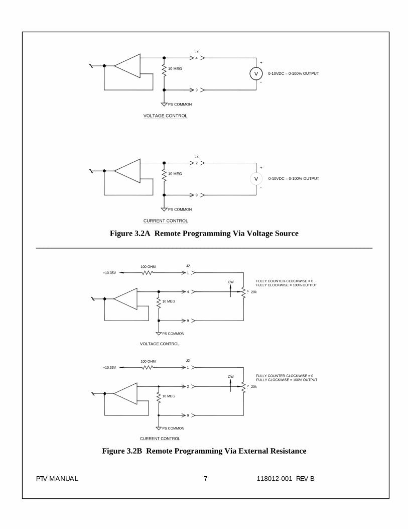
REMOTE PROGRAMMING: Allows remote adjustment of the output voltage and current via an external voltage source. 0-10VDC signal is supplied to Pin 4 of the control input connector for voltage programming and 0-10 VDC signal is supplied to Pin 2 of the control input connector for current programming. Programming signals should be referenced to Pin 9 of the control input connector signal ground. By adjusting the voltage source from 0 volts (zero output) to 10 volts (full rated output) the desired output can be selected. See Figure 3-2 A for wiring diagram and specifications.
An alternate method of controlling the output remotely is by using external resistance such as a potentiometer or a resistor network. See Figure 3.2B for wiring diagram.
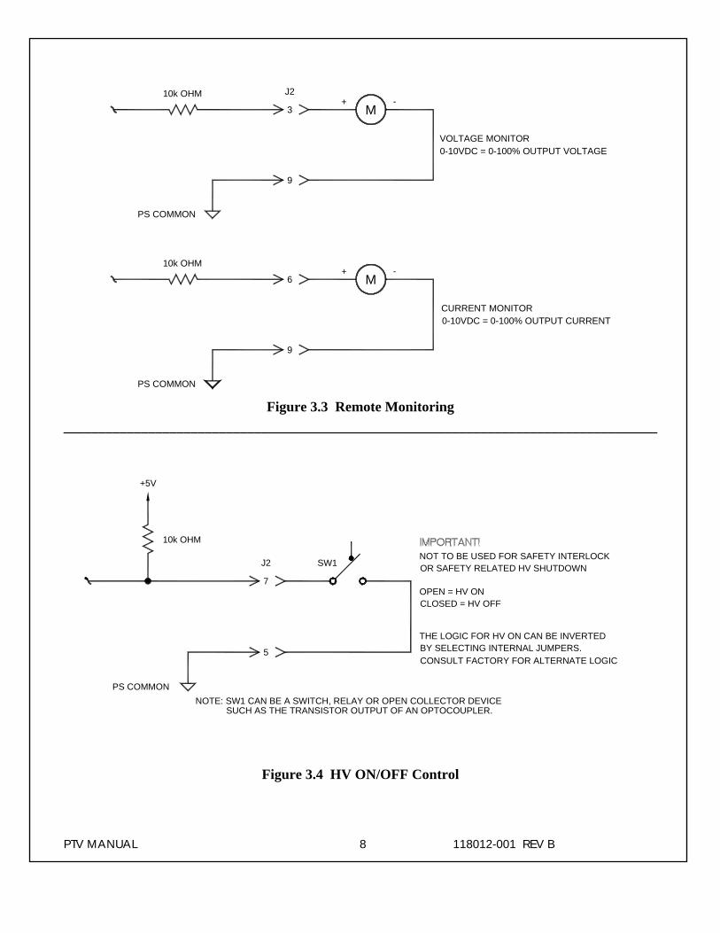
Remote Monitoring: Test points are made available for monitoring the voltage and current output. The test points are always positive regardless of the output polarity, where zero (0) to 10 (10) volts equals 0-100% of output. See Figure 3.3 for test point wiring.
Enable/Disable Control: Remote control of the high voltage on and high voltage off can be done via the enable/disable logic control. See Figure 3.4 for recommended interface circuits.
WARNING
It is extremely dangerous to use this circuit to inhibit high voltage generation
for the purpose of servicing or approaching any area of load considered
unsafe during normal use. OVP Indicator/Power Supply On Indicator: A logic signal is provided which can be used to determine if the OVP Shutdown Circuit is active, and/or if the power supply is ON. See Figure 3.5
PTV MANUAL 7 118012-001 REV B
10 MEG
4
9
PS COMMON
VOLTAGE CONTROL
CURRENT CONTROL
J2
0-10VDC = 0-100% OUTPUTV-
+
PS COMMON
10 MEG
9
-
J2
2
0-10VDC = 0-100% OUTPUTV
+
Figure 3.2A Remote Programming Via Voltage Source ____________________________________________________________________________________
10 MEG
4
9
PS COMMON
VOLTAGE CONTROL
FULLY COUNTER-CLOCKWISE = 0
CURRENT CONTROL
>- 20k
CW
1
J2100 OHM
+10.35V
FULLY CLOCKWISE = 100% OUTPUT
10 MEG
PS COMMON
+10.35V
100 OHM
9
FULLY COUNTER-CLOCKWISE = 0FULLY CLOCKWISE = 100% OUTPUT
2
1
J2
CW
>- 20k
Figure 3.2B Remote Programming Via External Resistance
PTV MANUAL 8 118012-001 REV B
3
J2
9
PS COMMON
M-+
VOLTAGE MONITOR
10k OHM
0-10VDC = 0-100% OUTPUT VOLTAGE
PS COMMON
10k OHM
9
0-10VDC = 0-100% OUTPUT CURRENT
6+
M-
CURRENT MONITOR
Figure 3.3 Remote Monitoring ____________________________________________________________________________________
7
J2
5
PS COMMON
10k OHM
NOT TO BE USED FOR SAFETY INTERLOCKOR SAFETY RELATED HV SHUTDOWN
CLOSED = HV OFFOPEN = HV ON
THE LOGIC FOR HV ON CAN BE INVERTEDBY SELECTING INTERNAL JUMPERS.CONSULT FACTORY FOR ALTERNATE LOGIC
SW1
+5V
SUCH AS THE TRANSISTOR OUTPUT OF AN OPTOCOUPLER.NOTE: SW1 CAN BE A SWITCH, RELAY OR OPEN COLLECTOR DEVICE
Figure 3.4 HV ON/OFF Control
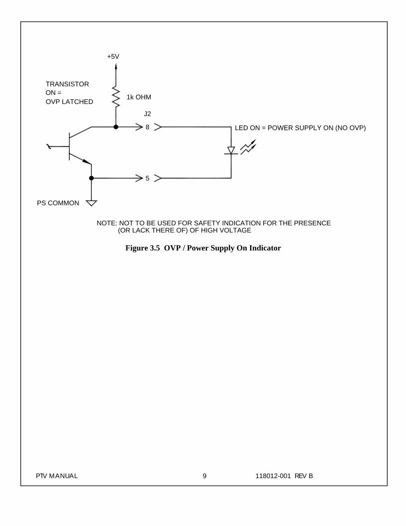
PTV MANUAL 9 118012-001 REV B
8
J2
5
PS COMMON
1k OHM
LED ON = POWER SUPPLY ON (NO OVP)
+5V
(OR LACK THERE OF) OF HIGH VOLTAGENOTE: NOT TO BE USED FOR SAFETY INDICATION FOR THE PRESENCE
TRANSISTORON =OVP LATCHED
Figure 3.5 OVP / Power Supply On Indicator
PTV MANUAL 10 118012-001 REV B
Chapter 4
PRINCIPLES OF OPERATIONhe PTV Series of high voltage power supplies utilizes sophisticated power conversion technology. Advanced analog and power conversion techniques
are used in the PTV series. The intention of the Principles of Operation is to introduce the basic function blocks that comprise the PTV power supply. For details on a specific circuit, consult Spellman’s Engineering Department.
The PTV power supply is basically an AC to DC power converter. Within the power supply, conversions of AC to DC then to high frequency AC, then to high voltage DC take place.
Typical PTV power supplies comprise a few basic building blocks. These are: 1) AC to DC rectifier, 2) High frequency quasi-resonant inverter, 3) High voltage transformer and rectifier circuits, and 4) Control and monitoring circuits. The following is a brief description of each building block.
4.1 AC to DC Rectifier and Associated Circuits The PTV series can operate from 115VAC +/- 10% or 220VAC +/- 10%. (Alternate input voltage ranges can be accommodated. Consult Spellman’s Sales Department for details).
The input voltage is connected via a typical IEC 320 type input connector. An internal EMI filter and fuse housing is an integral part of the IEC input module.
WARNING
To reduce the risk of fire, replace fuse with same type and rating.
The input line voltage is applied to a current limit device to reduce the initial inrush current. The input line voltage is converted to a 300VDC voltage via a bridge rectifier/capacitor filter circuit.
On newer PTV modules a 300VDC indicator neon lamp is provided inside the unit to indicate the presence of voltage.
The input AC line voltage is also connected to a step-down transformer, which is used to generate +/- 24VDC, +/- 15VDC, and 10VDC via low voltage regulators.
WARNING The energy levels used and generated by the
power supply can be lethal! Do not attempt to operate the power supply unless the user has a
sufficient knowledge of the dangers and hazards of working with high voltage. Do not attempt to
approach or touch any internal or external circuits or components that are connected or have been connected to the power supply. Be
certain to discharge any stored energy that may be present before and after the power supply is used. Consult IEEE recommended practices for
safety in high voltage testing #510-1983.
4.2 High Frequency Inverter The PTV is a resonant converter operating in a zero current switching, series resonant, parallel loaded topology. MOSFET transistors switch the 300 VDC voltage to the resonant tank circuit. Typical operating frequency is in the range of 35-65KHz depending on model. Control of the resonant circuit output is done by the low voltage control circuits, and are isolated by an isolated pulse transformer. The output of the resonant circuit is applied to the primary of the high voltage transformer.
4.3 High Voltage Circuits The high voltage transformer is a step-up type. The secondary of the high voltage transformer is connected to the high voltage rectifier circuit. The rectifier circuit will vary depending upon the rated output voltage. For lower output voltage, a full bridge or doubler circuit is used. For higher voltages, a half wave Cockroft-Walton multiplier is used. A feedback signal is generated by the high voltage resistor divider. This feedback signal is sent to control circuits to provide voltage regulation and monitoring. A current sense resistor is connected at the low voltage end of the rectifier circuit. The circuit sense signal is sent to the control circuits to provide current regulation and monitoring.
An auxiliary voltage sense signal is generated by the overvoltage protection feedback resistor. This is used to provide overvoltage protection.
T
PTV MANUAL 11 118012-001 REV B
The high voltage rectifier output is connected to an R-C type filter to reduce high frequency ripple components. The filter is then connected to the output limiting resistors. These resistors limit the peak surge current in the event an arc or discharge occurs. The limiting resistor output is connected to the output cable or connector provided.
4.4 Control Circuits Control circuits are used for regulation, monitoring, pulse-width, control, slow-start and inhibit control. Feedback signals are calibrated and buffered via general purpose OP-AMPS. Pulse width control is accomplished by a typical PWM type control I.C. Logic enable/disable is provided by a logic gate I.C. As stated previously, regulators generate +/- 15V and 10VDC.
WARNING
LINE VOLTAGE IS PRESENT WHENEVER THE POWER SUPPLY IS
CONNECTED TO EXTERNAL LINE VOLTAGES. BE SURE TO DISCONNECT THE LINE CORD BEFORE OPENING THE
UNIT. ALLOW 5 MINUTES FOR INTERNAL CAPACITANCE TO
DISCHARGE BEFORE REMOVING ANY COVER.
4.5 Options Due to the variations of models and options provided in the PTV series, details of actual circuits used may differ slightly from above descriptions. Consult Spellman’s Engineering Department for questions regarding the principles of operations for the PTV series.
PTV MANUAL 12 118012-001 REV B
Chapter 5
OPTIONS
He options available for this power supply are described in this section. Interface diagrams are shown where required. Options are specified by
including the option code in the model number as described in Section 1.4.
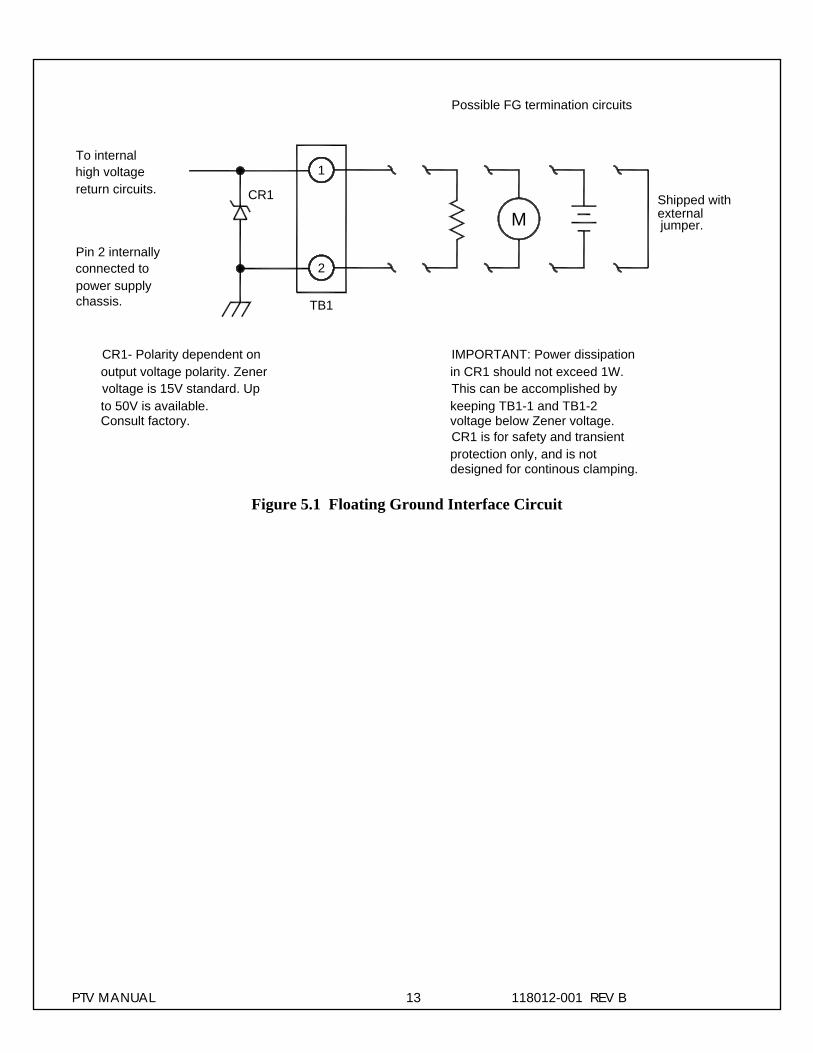
5.1 Floating Ground FG The floating ground option allows isolation of the power supply common from chassis ground. A typical application for FG is for connection of an external meter or circuit into the FG signal point. This circuit can monitor actual current flow at a low voltage level. See Figure 5.1 for typical connection to the floating ground terminal.
WARNING
The power supply common must be connected to chassis ground through a
low impedance circuit. The power supply common is clamped to chassis
ground using a power Zener diode. This diode is not intended to clamp under
continuous operation. On higher current units the power dissipation
within the Zener diode can be excessive if allowed to clamp.
5.2 220V AC Single Phase Input 220 PTV power supplies with the 220 V AC input option will operate from an input voltage of 220VAC rms ±10%, 50-60hZ, single phase.
5.3 No Slow Start NSS The no slow start option causes the output voltage of the power supply to rise (within 50 msec) to the rated voltage upon Power Up.
5.4 Non-Standard Slow Start SS(x) The non-standard slow start option allows the gradual rise time of the output voltage to be different from the standard of six seconds. To order the option, place the time desired in seconds after the suffix letter; i.e. SS(10) denotes a 10 second rise time.
5.5 Extra Length Output Cable LL(ft) Standard output cable is 18”long. Other lengths may be specified.
5.6 Focus Outputs Focus outputs for CRT type applications can be provided. Generally, the focus output range is 6kV – 12kV, <1mA. Specific focus output requirements should be discussed with Spellman’s sales department. Multiple focus, dynamis focus and variable focus control can also be provided.
5.7 Grid Outputs Grid outputs for CRT type applications can be provided. Grid outputs can either be fixed or adjustable. Generally, grid outputs are in the ranges of a few hundred volts to 1800V, = 1mA. Specific grid output requirements should be discussed with Spellman’s sales department.
5.8 Custon Designed Models X(#) Units built to customer specifications are assigned an X number be the factory. If this unit is an X model, specification control sheet is added at the end of this instruction manual.
Spellman welcomes the opportunity to tailor units to fit your requirements or to develop new products for your applications. Contact Spellman Sales Department.
Note: Before operating this system, refer to operating instructions in Chapter 3.
T
PTV MANUAL 13 118012-001 REV B
1
TB1
2
Shipped with
output voltage polarity. ZenerCR1- Polarity dependent on
To internalhigh voltagereturn circuits.
Pin 2 internallyconnected topower supplychassis.
CR1
voltage is 15V standard. Upto 50V is available.Consult factory.
externaljumper.M
IMPORTANT: Power dissipation
This can be accomplished byin CR1 should not exceed 1W.
keeping TB1-1 and TB1-2voltage below Zener voltage.
designed for continous clamping.protection only, and is notCR1 is for safety and transient
Possible FG termination circuits
Figure 5.1 Floating Ground Interface Circuit
PTV MANUAL 14 118012-001 REV B
Chapter 6
MAINTENANCE
his section describes periodic servicing and performance testing procedures.
THIS POWER SUPPLY GENERATES VOLTAGES THAT ARE DANGEROUS AND MAY BE FATAL .
OBSERVE EXTREME CAUTION WHEN WORKING WITH HIGH VOLTAGE.
6.1 Periodic Servicing Approximately once a year (more often in high dust environments), disconnect the power to the unit and remove the top cover. Use compressed air to blow dust out of the inside of the unit. Avoid touching or handling the high voltage assembly.
6.2 Performance Test
HIGH VOLTAGE IS DANGEROUS.
ONLY QUALIFIED PERSONNEL SHOULD PERFORM THESE TESTS.
High voltage test procedures are described in Bulletin STP-783, Standard Test Procedures for High Voltage Power Supplies. Copies can be obtained from the Spellman Customer Service Department. Test equipment, including an oscilloscope, a high impedance voltmeter, and a high voltage divider such as the Spellman HVD-100 or HVD-200, is needed for performance tests. All test components must be rated for operating voltage.
6.3 High Voltage Dividers High voltage dividers for precise measurements of output voltage with an accuracy up to 0.1% are available from Spellman. The HVD-100 is used for voltages up to 100KV. The HVD-200 measures up to 200KV. The Spellman divider is designed for use with differential voltmeters or high impedance digital voltmeters. The high input impedance is ideal for measuring high voltage low current sources, which would be overloaded by traditional lower impedance dividers.
T WARNING
WARNING
PTV MANUAL 15 118012-001 REV B
Chapter 7
REPLACEMENT PARTS7.1 Replacement Parts
Pellman provides parts and assemblies for its high voltage power supplies but recommends that only qualified personnel perform the repair. High voltage
is dangerous; even minor mistakes in repairs can have serious consequences.
When requesting parts please give the model number and serial number of the power supply. See Recommended Spare Parts PTV200 on page 16 for a list of standard replacement parts.
7.2 Correspondence and Ordering Spare Parts
Each Spellman power supply has an identification label on the rear of the chassis that bears its model and serial number.
When requesting engineering or applications information, please state the model and serial number of the power supply. If specific components or circuit sections are involved in the inquiry, it is helpful to indicate the component symbol number(s) shown on the applicable schematic diagram.
When ordering spare parts, please specify the part’s description, the part’s reference designation or part number, and the model and serial number of the unit. Example: Two Transistors, Mosfet IRFP450F1 for Model PTV40P200 Power Supply, serial # C01225.
S
PTV MANUAL 16 118012-001 REV B
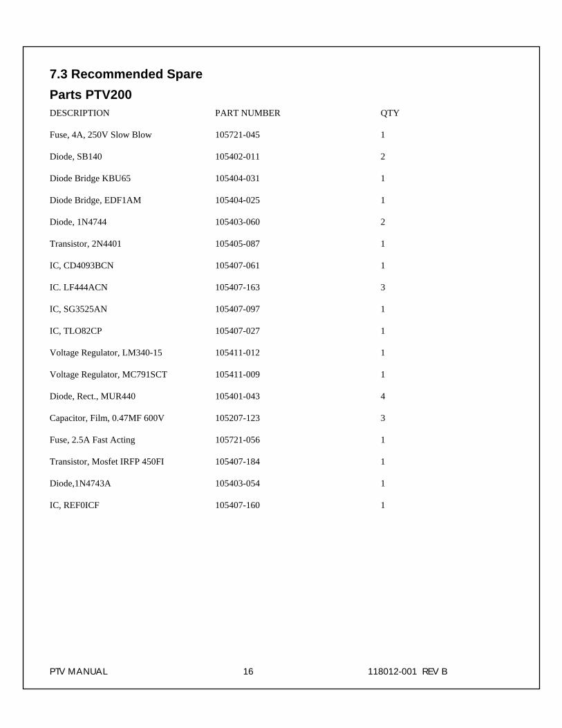
7.3 Recommended Spare Parts PTV200 DESCRIPTION PART NUMBER QTY
Fuse, 4A, 250V Slow Blow 105721-045 1
Diode, SB140 105402-011 2
Diode Bridge KBU65 105404-031 1
Diode Bridge, EDF1AM 105404-025 1
Diode, 1N4744 105403-060 2
Transistor, 2N4401 105405-087 1
IC, CD4093BCN 105407-061 1
IC. LF444ACN 105407-163 3
IC, SG3525AN 105407-097 1
IC, TLO82CP 105407-027 1
Voltage Regulator, LM340-15 105411-012 1
Voltage Regulator, MC791SCT 105411-009 1
Diode, Rect., MUR440 105401-043 4
Capacitor, Film, 0.47MF 600V 105207-123 3
Fuse, 2.5A Fast Acting 105721-056 1
Transistor, Mosfet IRFP 450FI 105407-184 1
Diode,1N4743A 105403-054 1
IC, REF0ICF 105407-160 1
PTV MANUAL 17 118012-001 REV B
Chapter 8
FACTORY SERVICE 8.1 Warranty Repairs During the Warranty period, Spellman will repair all units free of charge. The Warranty is void if the unit is worked on by other than Spellman personnel. See the Warranty in the rear of this manual for more information. Follow the return procedures described in Section 8.2. The customer shall pay for shipping to and from Spellman.
8.2 Factory Service Procedures Spellman has a well-equipped factory repair department. If a unit is returned to the factory for calibration or repair, a detailed description of the specific problem should be attached.
For all units returned for repair, please obtain an authorization to ship from the Customer Service Department, either by phone or mail prior to shipping. When you call, please state the model and serial numbers, which are on the plate on the rear of the power supply, and the purchase order number for the repair. A Return Material Authorization Code Number (RMA Number) is needed for all returns. This RMA Number should be marked clearly on the outside of the shipping container. Packages received without an RMA Number will be returned to the customer. The Customer shall pay for shipping to and from Spellman.
A preliminary estimate for repairs will be given by phone by Customer Service. A purchase order for this amount is requested upon issuance of the RMA Number. A more detailed estimate will be made when the power supply is received at the Spellman Repair Center. In the event that repair work is extensive, Spellman will call to seek additional authorization from your company before completing the repairs.
8.3 Ordering Options and Modifications many of the options listed in Chapter 5 can be retrofitted into Spellman power supplies by our factory. For prices and arrangements, contact our Sales Department.
8.4 Shipping Instructions All power supplies returned to Spellman must be sent shipping prepaid. Pack the units carefully and securely in a suitable container, preferably in the original container, if available. The power supply should be surrounded by at least four inches of shock absorbing material. Please return all associated materials, i.e. high voltage output cables, interconnection cables, etc., so that we can examine and test the entire system.
All correspondence and phone calls should be directed to:
Spellman High Voltage Electronics Corp. 475 Wireless Boulevard Hauppauge, New York 11788 TEL: (631) 630-3000 FAX: (631) 435-1620 E-Mail: [email protected] http://www.spellmanhv.com
101520-007 REV D
SPELLMAN HIGH VOLTAGE ELECTRONICS
WARRANTY
Spellman High Voltage Electronics (“Spellman”) warrants that all power supplies it manufactures will be free from defects in materials and factory workmanship, and agrees to repair or replace, without charge, any power supply that under normal use, operating conditions and maintenance reveals during the warranty period a defect in materials or factory workmanship. The warranty period is twelve (12) months from the date of shipment of the power supply. With respect to standard SL power supplies (not customized) the warranty period is thirty-six (36) months from the date of shipment of the power supply.
This warranty does not apply to any power supply that has been:
• Disassembled, altered, tampered, repaired or worked on by persons unauthorized by Spellman; • subjected to misuse, negligent handling, or accident not caused by the power supply; • installed, connected, adjusted, or used other than in accordance with the original intended application and/or
instructions furnished by Spellman.
THE FOREGOING WARRANTY IS IN LIEU OF ALL OTHER WARRANTIES, EXPRESS OR IMPLIED, INCLUDING THOSE OF MERCHANTABILITY OR FITNESS FOR A PARTICULAR PURPOSE.
The buyer’s sole remedy for a claimed breach of this warranty, and Spellman’s sole liability is limited, at Spellman’s discretion, to a refund of the purchase price or the repair or replacement of the power supply at Spellman’s cost. The buyer will be responsible for shipping charges to and from Spellman’s plant. The buyer will not be entitled to make claim for, or recover, any anticipatory profits, or incidental, special or consequential damages resulting from, or in any way relating to, an alleged breach of this warranty.
No modification, amendment, supplement, addition, or other variation of this warranty will be binding unless it is set forth in a written instrument signed by an authorized officer of Spellman.
Factory Service Procedures
For an authorization to ship contact Spellman’s Customer Service Department. Please state the model and serial numbers, which are on the plate on the rear panel of the power supply and the reason for return. A Return Material Authorization Code Number (RMA number) is needed from Spellman for all returns. The RMA number should be marked clearly on the outside of the shipping container. Packages received without an RMA Number may delay return of the product. The buyer shall pay shipping costs to and from Spellman. Customer Service will provide the Standard Cost for out-of-warranty repairs. A purchase order for this amount is requested upon issuance of the RMA Number (in-warranty returns must also be accompanied by a “zero-value” purchase order). A more detailed estimate may be made when the power supply is received at Spellman. In the event that the cost of the actual repair exceeds the estimate, Spellman will contact the customer to authorize the repair.
Factory Service Warranty
Spellman will warrant for three (3) months or balance of product warranty, whichever is longer, the repaired assembly/part/unit. If the same problem shall occur within this warranty period Spellman shall undertake all the work to rectify the problem with no charge and/or cost to the buyer. Should the cause of the problem be proven to have a source different from the one that has caused the previous problem and/or negligence of the buyer, Spellman will be entitled to be paid for the repair.
Spellman Worldwide Service Centers
For a complete listing of Spellman’s Global Service facilities please go to: http://www.spellmanhv.com/customerservice/service.asp